Gianluigi Ciovati Thomas Jefferson National Accelerator ...
97
Slide 1 of 97 SURFACE PREPARATION Gianluigi Ciovati Thomas Jefferson National Accelerator Facility USPAS June 2015 Rutgers
Transcript of Gianluigi Ciovati Thomas Jefferson National Accelerator ...

Slide 1 of 97
SURFACE PREPARATION
Gianluigi Ciovati
Thomas Jefferson National Accelerator Facility
USPAS June 2015 Rutgers

Slide 2 of 97
Required Procedures for Qualifying SRF Cavities
• Degreasing surfaces to remove contaminates
• Chemical removal of exterior films incurred from welding
• Removal of damage layer of niobium from fabrication (150 mm)
• Removal of hydrogen from bulk Nb
• Mechanical tuning
• Chemical removal of internal surface for clean assembly (10-20 mm)
– Additional “cleaning” steps if Electropolishing (EP) is used
• High Pressure Rinsing (HPR) to remove particulates from interior
surfaces (incurred during chemistry and handling)
• Drying of cavity for assembly in cleanroom (reduce risk of particulate
adhesion and reduce wear on vacuum systems)
• Clean assembly
• Clean evacuation
• Low-temperature baking
If cavity meets specs after cryo-RF test…
Slide 3 of 97
Additional Steps for Cavity String
• Final mechanical tuning
• He-vessel welding
• Degreasing
• Final material removal (10-20 mm)
• Final HPR
• Horizontal assembly into cavity-string
• Evacuation of cavity string
Slide 4 of 97
Required Procedures for Qualifying SRF Cavities
• Degreasing surfaces to remove contaminates
• Chemical removal of exterior films incurred from welding
• Removal of damage layer of niobium from fabrication (150 mm)
• Removal of hydrogen from bulk Nb
• Mechanical tuning
• Chemical removal of internal surface for clean assembly (10-20 mm)
– Additional “cleaning” steps if Electropolishing (EP) is used
• High Pressure Rinsing (HPR) to remove particulates from interior
surfaces (incurred during chemistry and handling)
• Drying of cavity for assembly in cleanroom (reduce risk of particulate
adhesion and reduce wear on vacuum systems)
• Clean assembly
• Clean evacuation
• Low-temperature baking
Slide 5 of 97
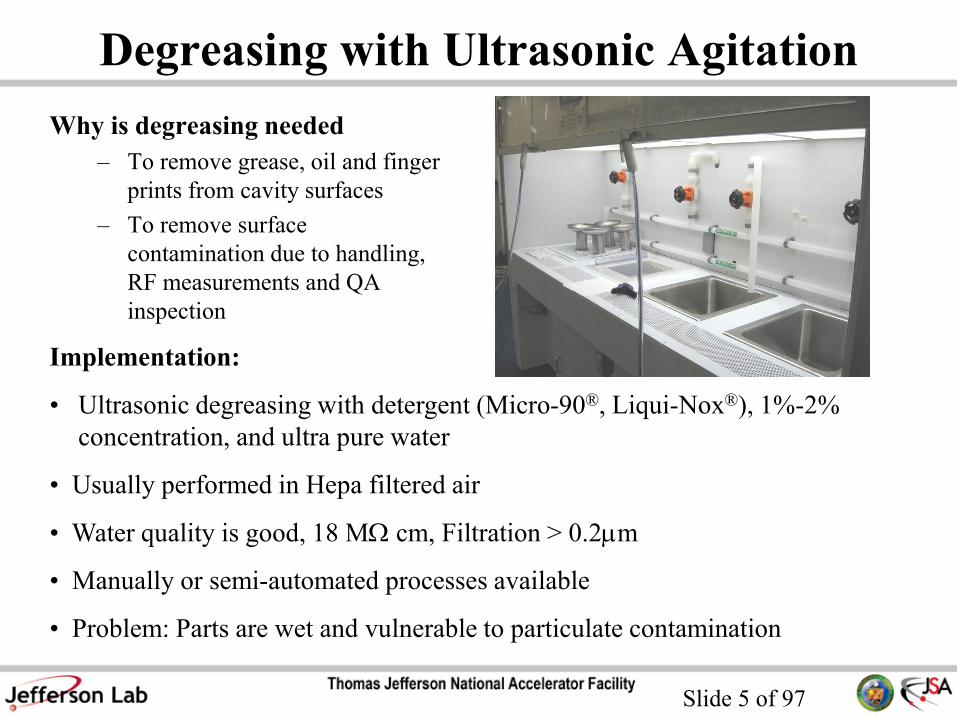
Degreasing with Ultrasonic Agitation
Why is degreasing needed
– To remove grease, oil and finger
prints from cavity surfaces
– To remove surface
contamination due to handling,
RF measurements and QA
inspection
Implementation:
• Ultrasonic degreasing with detergent (Micro-90®, Liqui-Nox®), 1%-2%
concentration, and ultra pure water
• Usually performed in Hepa filtered air
• Water quality is good, 18 MW cm, Filtration > 0.2mm
• Manually or semi-automated processes available
• Problem: Parts are wet and vulnerable to particulate contamination
Slide 6 of 97
Ultrasonic Cleaning
• Immersion of components in DI water and detergent medium
• Wave energy forms microscopic bubbles on component surfaces.
Bubbles collapse (cavitation) on surface loosening particulate matter.
• Transducer provides high intensity ultrasonic fields that set up standing
waves. Higher frequencies lowers the distance between nodes which
produce less dead zones with no cavitation.
• Ultrasonic transducers are available in many different wave
frequencies from 18 kHz to 120 kHz, the higher the frequency the
lower the wave intensity.
Cavities and all hardware components (Flanges, nuts & bolts…)
have to be degreased with ultrasonic cleaning

Slide 7 of 97
Megasonic Cleaning

Slide 8 of 97
Studies on Efficient Cleaning Methods

Slide 9 of 97
Example on Nb Sample
Test on cleaning procedure/detergent: Nb sample polluted with
grease and oil

Slide 10 of 97
Ultrasonic Tanks for Cavity Cleaning
Ultrasonic cleaning tank at DESY (up to 4 kW power)

Slide 11 of 97
Required Procedures for Qualifying SRF Cavities
• Degreasing surfaces to remove contaminates
• Chemical removal of exterior films incurred from welding
• Removal of damage layer of niobium from fabrication (150 mm)
• Removal of hydrogen from bulk Nb
• Mechanical tuning
• Chemical removal of internal surface for clean assembly (10-20 mm)
– Additional “cleaning” steps if Electropolishing (EP) is used
• High Pressure Rinsing (HPR) to remove particulates from interior
surfaces (incurred during chemistry and handling)
• Drying of cavity for assembly in clean room (reduce risk of particulate
adhesion and reduce wear on vacuum systems)
• Clean assembly
• Clean evacuation
Chemical:• Buffered Chemical Polishing
(BCP)
• Electropolishing (EP)
MechanicalCentrifugal Barrel Polishing
(CBP)
Slide 12 of 97
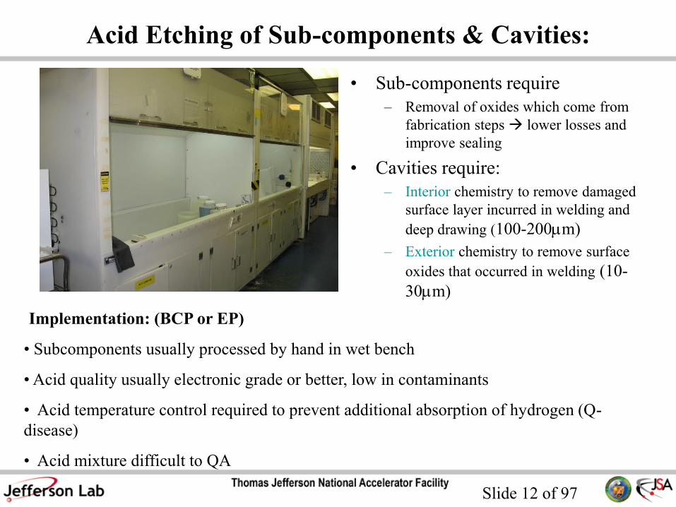
Acid Etching of Sub-components & Cavities:
• Sub-components require
– Removal of oxides which come from
fabrication steps lower losses and
improve sealing
• Cavities require:
– Interior chemistry to remove damaged
surface layer incurred in welding and
deep drawing (100-200mm)
– Exterior chemistry to remove surface
oxides that occurred in welding (10-
30mm)
Implementation: (BCP or EP)
• Subcomponents usually processed by hand in wet bench
• Acid quality usually electronic grade or better, low in contaminants
• Acid temperature control required to prevent additional absorption of hydrogen (Q-
disease)
• Acid mixture difficult to QA
Slide 13 of 97
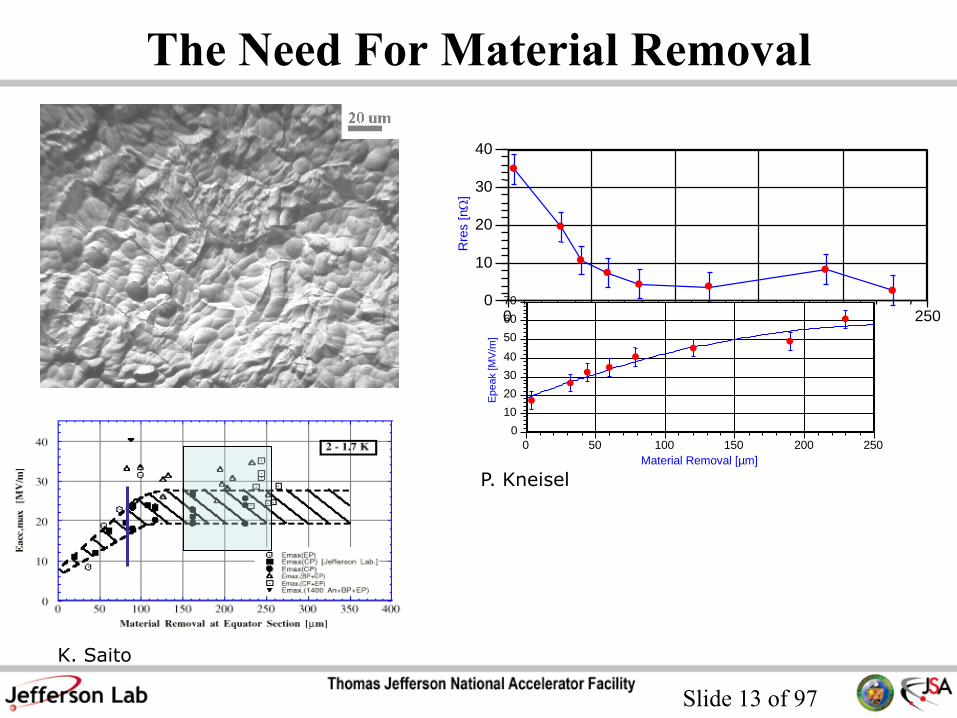
The Need For Material Removal
•
•
• • • • •
• 0
10
20
30
40
0 50 100 150 200 250
Rre
s [
nW
]
Material Removal [µm]
•
• • •
• •
•
•
0
10
20
30
40
50
60
70
0 50 100 150 200 250
Epeak [M
V/m
]
Material Removal [µm]
K. Saito
P. Kneisel

Slide 14 of 97
Nb Surface
Nb2O5 ( 5 nm thick)
Nb
Sub-oxides (NbOx, x = 2 – 0.5)
Interstitials (O, H, Ta)

Slide 15 of 97
Buffered Chemical Polish (BCP)
HF (49%), HNO3 (65%), H3PO4 (85%)
Mixture 1:1:1 , or 1:1:2 by volume typical
Oxidation
2Nb + 5HNO3 Nb2O5 + 5NO2
Reduction
Nb2O5 + 6HF H2NbOF5 + NbO2F 0.5H2O + 1.5H2O
NbO2F 0.5H2O + 4HF H2NbOF5 + 1.5H2O
Reaction exothermic! Use H3PO4 as “buffer” to slow reaction rate
Brown gas
Slide 16 of 97
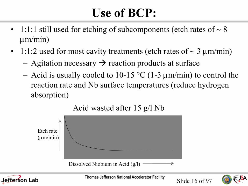
Use of BCP:
• 1:1:1 still used for etching of subcomponents (etch rates of 8
mm/min)
• 1:1:2 used for most cavity treatments (etch rates of 3 mm/min)
– Agitation necessary reaction products at surface
– Acid is usually cooled to 10-15 °C (1-3 mm/min) to control the
reaction rate and Nb surface temperatures (reduce hydrogen
absorption)
Acid wasted after 15 g/l Nb
Dissolved Niobium in Acid (g/l)
Etch rate
(mm/min)

Slide 17 of 97
BCP: Surface Roughness and Etching Rate
• “Simple” process
• Roughness of 2 -5 mm (100 x 100 mm2
scale) after 100 mm etching
• High etching rate100 mm
Slide 18 of 97
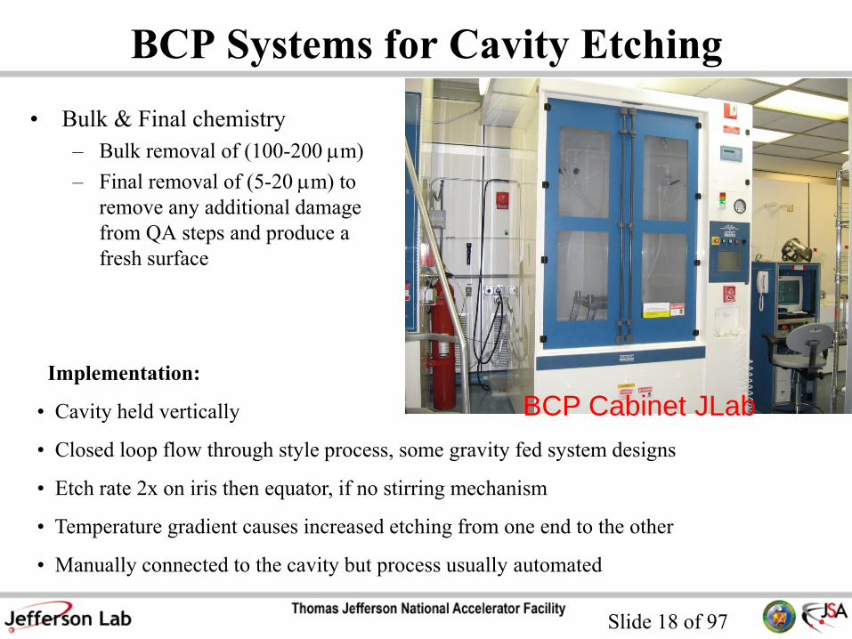
BCP Systems for Cavity Etching
• Bulk & Final chemistry
– Bulk removal of (100-200 mm)
– Final removal of (5-20 mm) to
remove any additional damage
from QA steps and produce a
fresh surface
Implementation:
• Cavity held vertically
• Closed loop flow through style process, some gravity fed system designs
• Etch rate 2x on iris then equator, if no stirring mechanism
• Temperature gradient causes increased etching from one end to the other
• Manually connected to the cavity but process usually automated
BCP Cabinet JLab
Slide 19 of 97
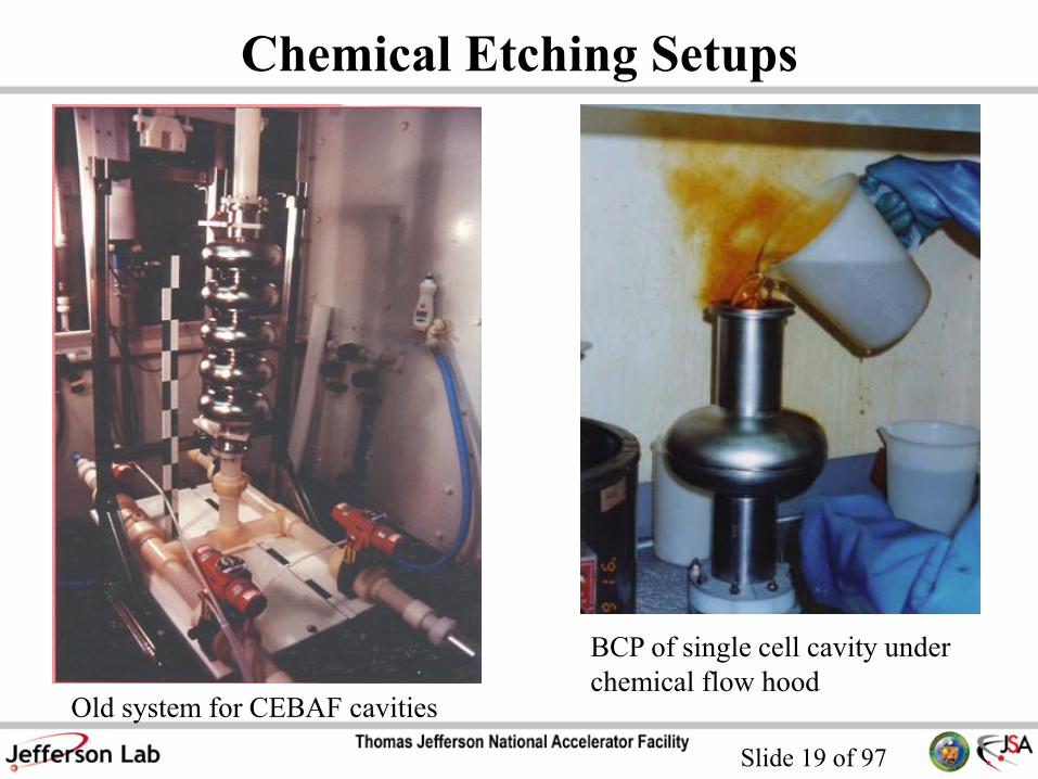
Chemical Etching Setups
Old system for CEBAF cavities
BCP of single cell cavity under
chemical flow hood

Slide 20 of 97
Chemical Etching of Outer Surface
• 20 um are removed from the outer surface of the cavity
by BCP to remove “dirty” layer after fabrication in order to
improve the heat transfer at the Nb/LHe interface (Kapitza
resistance)
• Some labs do this as part of cavity preparation procedure
(DESY), some don’t (JLab)
• No clear influence on cavity performance

Slide 21 of 97
Electropolishing
Electropolishing (EP) of Niobium:
• Both electrodes are immersed in electrolyte
•A voltage is applied between Nb (anode)
and counter electrode (cathode, Al)
Basic reactions:
Oxidation
2Nb +5SO42- + 5H2O Nb2O5 +10H+ +5SO4
2- +10e-
Reduction
Nb2O5 + 6HF H2NbOF5 + NbO2F 0.5H2O + 1.5H2O
NbO2F 0.5H2O + 4HF H2NbOF5 + 1.5H2O
10H+ +10e- 5H2
9:1 Hydrogen gas produced at cathode

Slide 22 of 97
I-V Curve
Potential
V1 V2 V3
Curr
ent
Den
sity
• 0-V2: Concentration Polarization
occurs, active dilution of niobium
• V2-V3: Limiting Current Density,
viscous layer on niobium surface
• >V3: Additional Cathodic Processes
Occur, oxygen gas generated
Electrode potentials should be measured wrt a Reference Electrode!
Electrometer
+ _
Power Supply
+ _
A V
Nb Al
Ref
Electrode
“Plateau”
Slide 23 of 97
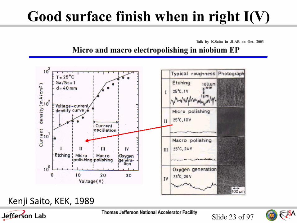
Good surface finish when in right I(V)
Kenji Saito, KEK, 1989

Slide 24 of 97
Basic Mechanism for EP
Compact Salt Film
( nm)
• Anodization of Nb in H2SO4 forces
growth of Nb2O5
• F- dissolves Nb2O5
• These competing processes result in
current flow and material removal
• Above a certain anodization potential,
the reaction rate plateaus, limited by
how fast fresh F- can arrive at the
surface (diffusion-limited)
• The diffusion coefficient sets a scale for
optimum leveling effects

Slide 25 of 97
EP: tricky process
• The current density (30-100 mA/cm2) in the plateau region:
– decreases linearly with lower HF/H2SO4 ratio
– increases with increasing temperature
• Temperature during the process is maintained between 25 –
35 °C
• Current oscillations often observed during polishing
(dynamic balance between oxide formation and dissolution).
It’s not a necessary condition for good surface finishing but
indication of good processing parameters (temperature,
voltage, agitation, HF concentration)
Finding the right balance among the processing parameters becomes
complicated when polishing multi-cell cavities!

Slide 26 of 97
EP: Smooth Surface
100 mm
Typical roughness of 1 mm (100 x 100 mm2 scale)
Slide 27 of 97
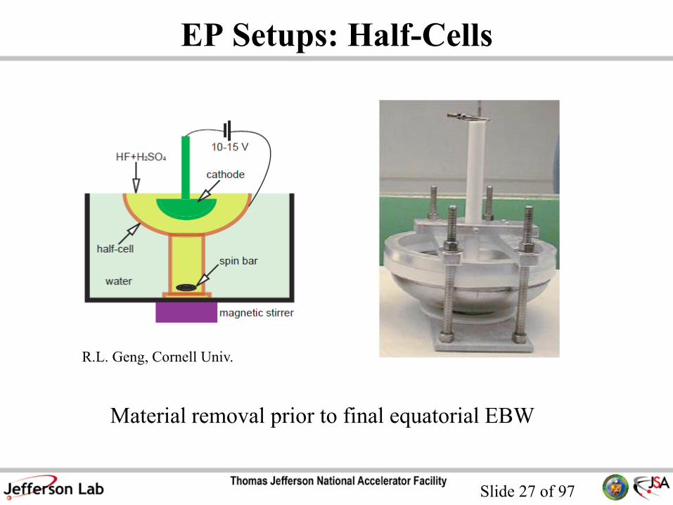
EP Setups: Half-Cells
Material removal prior to final equatorial EBW
R.L. Geng, Cornell Univ.

Slide 28 of 97
EP Systems: Single-Cell

Slide 29 of 97
EP Systems: Single-Cell
Single-Cell setup at CERN
Horizontal continuous electropolishing, polishing rate 0.3 mm/min
Slide 30 of 97
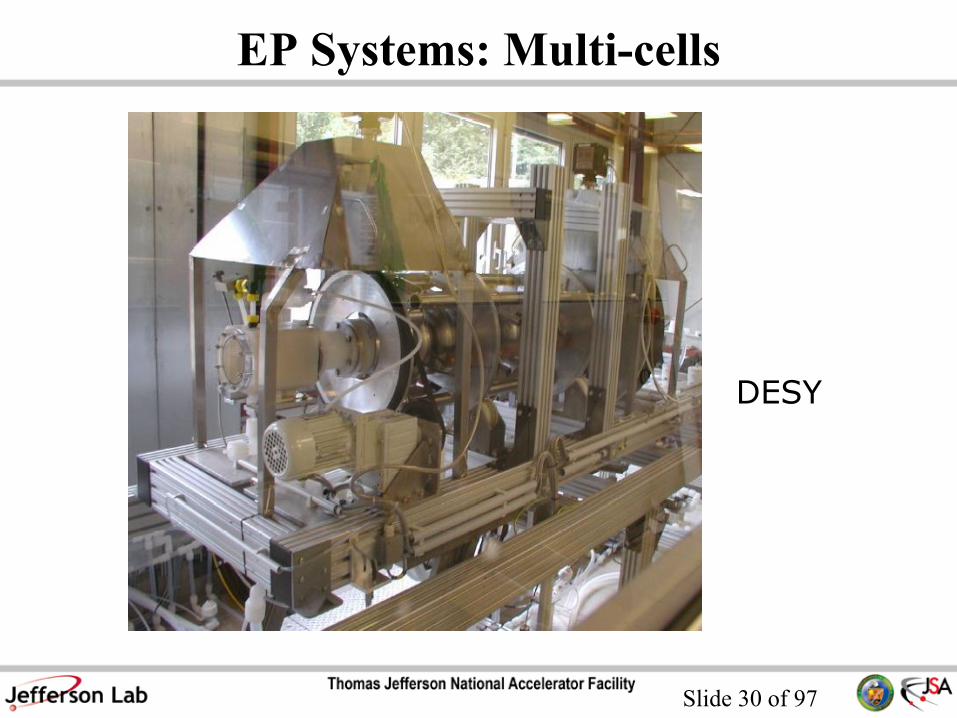
EP Systems: Multi-cells
DESY

Slide 31 of 97
EP Systems: Multi-cells
JLAB

Slide 32 of 97
EP Systems: Multi-cells
JLAB

Slide 33 of 97
EP Systems: Multi-cells
Nomura Plating and KEK
Slide 34 of 97
EP Issues
• HF disappears quickly from electrolyte due to surface temperature and
evaporation and must be added routinely
• Difficult to add HF to the Sulfuric, reaction looses HF plus adds water to
electrolyte which causes matt finishes
• Sulfur precipitates found on niobium surfaces (insoluble) and in system
piping (monoclinic), impossible to add meaningful filtration
• Removal of sulfuric from surfaces difficult and requires significant
amounts of DI water, hydrogen peroxide or alcohol rinses
• Typically cavity processed horizontally, slowly rotated
• Etch rate 2x on iris then equator
Why bother with EP?

Slide 35 of 97
EP: achieving high accelerating field
1999, KEK
Slide 36 of 97
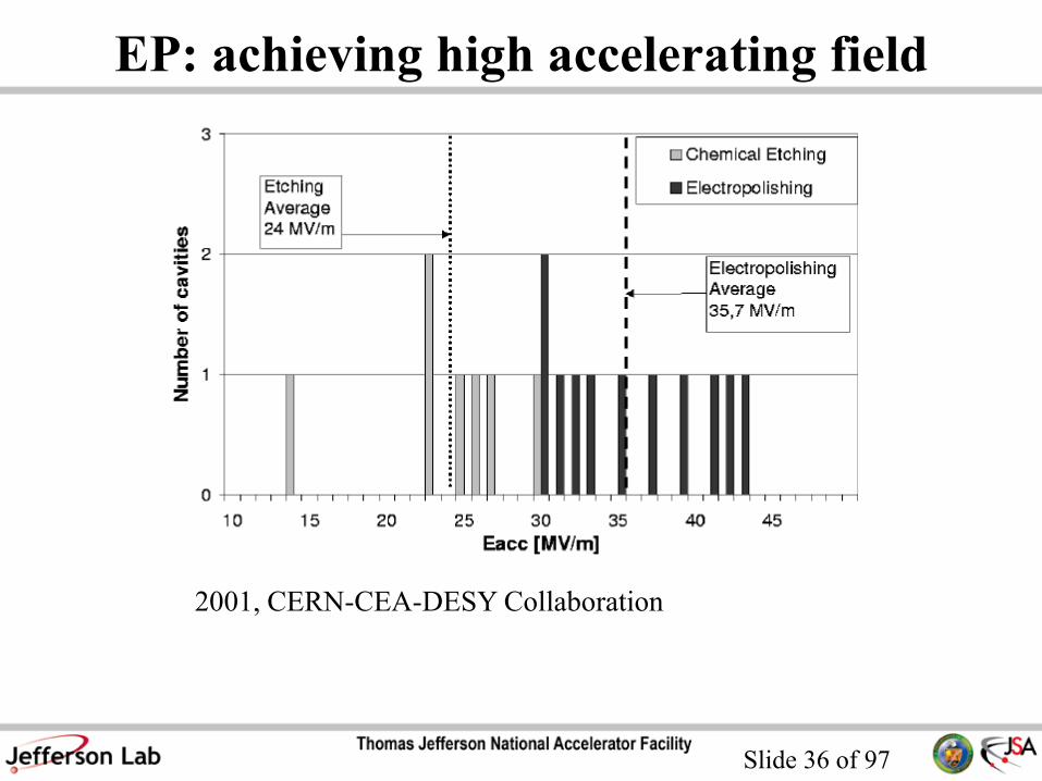
EP: achieving high accelerating field
2001, CERN-CEA-DESY Collaboration

Slide 37 of 97
EP: achieving high accelerating field
2009, JLab

Slide 38 of 97
EP: achieving high accelerating field
Slide 39 of 97
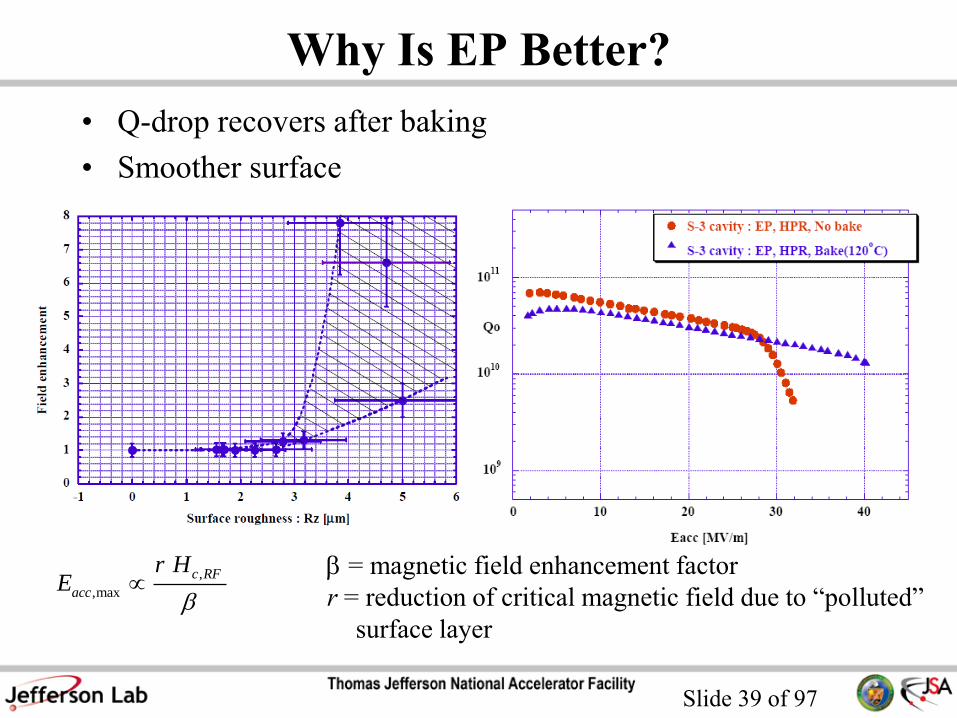
Why Is EP Better?
• Q-drop recovers after baking
• Smoother surface
,
,max
c RF
acc
r HE
= magnetic field enhancement factor
r = reduction of critical magnetic field due to “polluted”
surface layer

Slide 40 of 97
EP: used also in low- cavities for heavy ion accelerator
SRF cavities for ATLAS and future FRIB
Argonne Nat’l Lab

Slide 41 of 97
Vertical EP
• No rotary acid seals
• Twice removal rate than horizontally
rotating EP
• No sliding electrical contacts
• No large acid reservoir and heat
exchanger
Cornell Univ.
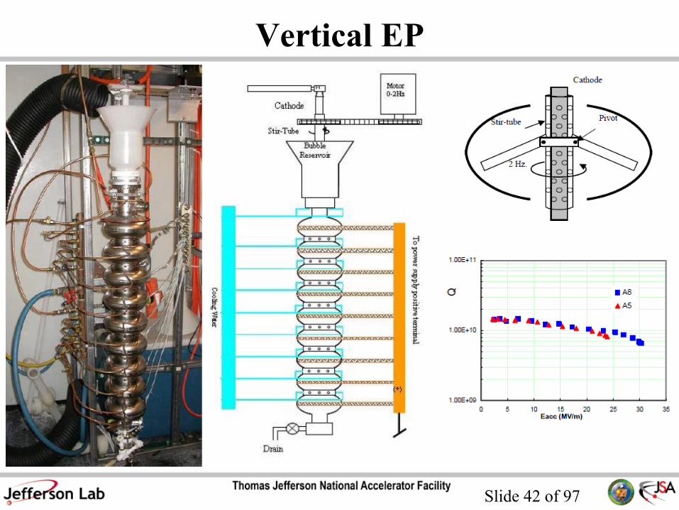
Slide 42 of 97
Vertical EP

Slide 43 of 97
Challenge to EP: Large Grain Nb & BCP
• Very reproducible performance
• Eacc 30 MV/m is possible

Slide 44 of 97
Large-Grain Nb Surface After BCP
Roughness of fine-grain Nb sample treated by EP is 250 nm

Slide 45 of 97
Challenge to EP: Large Grain Nb & BCP
• Studies at DESY show higher Eacc after EP even for large-grain Nb
• The typical performance of large-grain Nb cavities treated by BCP
would satisfy the requirements for most accelerator projects

Slide 46 of 97
Centrifugal Barrel Polishing
Developed in 2001 at KEK
Slide 47 of 97
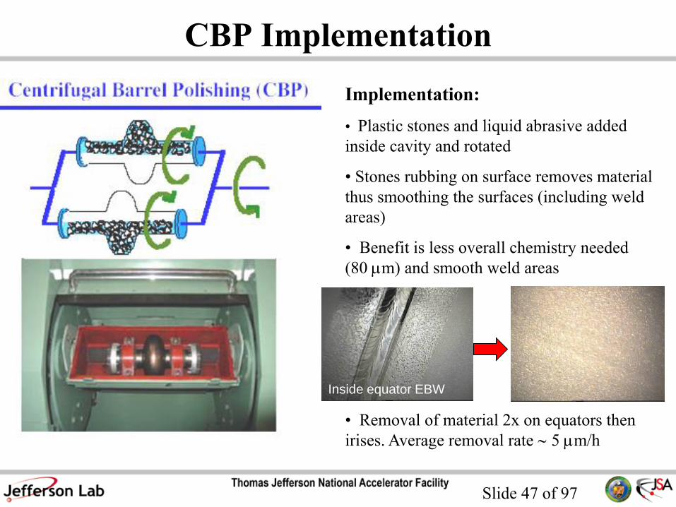
CBP Implementation
Implementation:
• Plastic stones and liquid abrasive added
inside cavity and rotated
• Stones rubbing on surface removes material
thus smoothing the surfaces (including weld
areas)
• Benefit is less overall chemistry needed
(80 mm) and smooth weld areas
• Removal of material 2x on equators then
irises. Average removal rate 5 mm/h
Inside equator EBW

Slide 48 of 97
Barrel Polishing Machine at JLab
• Removal rate 3 – 4 mm/h
Coarse Medium Fine
NEW USED
Coarse Medium Fine
Slide 49 of 97
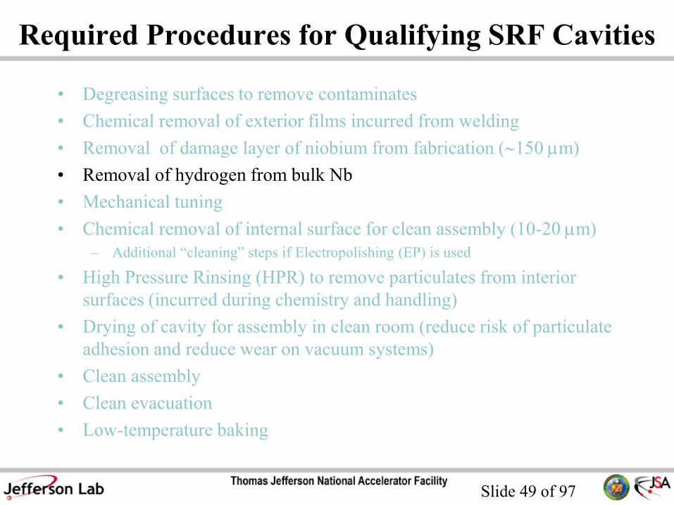
Required Procedures for Qualifying SRF Cavities
• Degreasing surfaces to remove contaminates
• Chemical removal of exterior films incurred from welding
• Removal of damage layer of niobium from fabrication (150 mm)
• Removal of hydrogen from bulk Nb
• Mechanical tuning
• Chemical removal of internal surface for clean assembly (10-20 mm)
– Additional “cleaning” steps if Electropolishing (EP) is used
• High Pressure Rinsing (HPR) to remove particulates from interior
surfaces (incurred during chemistry and handling)
• Drying of cavity for assembly in clean room (reduce risk of particulate
adhesion and reduce wear on vacuum systems)
• Clean assembly
• Clean evacuation
• Low-temperature baking

Slide 50 of 97
Heat Treatment for H-degassing
• H absorption occurs during chemical and/or mechanical
material removal
• Reduce bulk H concentration in Nb to avoid Q-disease
• The heat treatment also “stress-relieves” the Nb
• Different parameters at different labs:
– 600 °C/10 h at JLab
– 800 °C/2 h at DESY
– 750 °C/3 h at KEK

Slide 51 of 97
Heat Treatment Furnace at JLab up to
1250 °C, P 10-6 Torr
High Temperature Vacuum Furnace
Use Residual Gas Analyzer to monitor the partial pressure of residual
gases during heat treatment

Slide 52 of 97
Required Procedures for Qualifying SRF Cavities
• Degreasing surfaces to remove contaminates
• Chemical removal of exterior films incurred from welding
• Removal of damage layer of niobium from fabrication (150 mm)
• Removal of hydrogen from bulk Nb
• Mechanical tuning
• Chemical removal of internal surface for clean assembly (10-20 mm)
– Additional “cleaning” steps if Electropolishing (EP) is used
• High Pressure Rinsing (HPR) to remove particulates from interior
surfaces (incurred during chemistry and handling)
• Drying of cavity for assembly in clean room (reduce risk of particulate
adhesion and reduce wear on vacuum systems)
• Clean assembly
• Clean evacuation
• Low-temperature baking

Slide 53 of 97
Mechanical Tuning
• Small mechanical adjustments to the cavity’s cells to obtain
flat field profile and desired frequency
f
f
Slide 54 of 97
Post-EP Cleaning
• Degreasing surfaces to remove contaminates
• Chemical removal of exterior films incurred from welding
• Removal of damage layer of niobium from fabrication (150 mm)
• Removal of hydrogen from bulk Nb
• Mechanical tuning
• Chemical removal of internal surface for clean assembly (10-20 mm)
– Additional “cleaning” steps if Electropolishing (EP) is used
• High Pressure Rinsing (HPR) to remove particulates from interior
surfaces (incurred during chemistry and handling)
• Drying of cavity for assembly in clean room (reduce risk of particulate
adhesion and reduce wear on vacuum systems)
• Clean assembly
• Clean evacuation
• Low-temperature baking
Slide 55 of 97
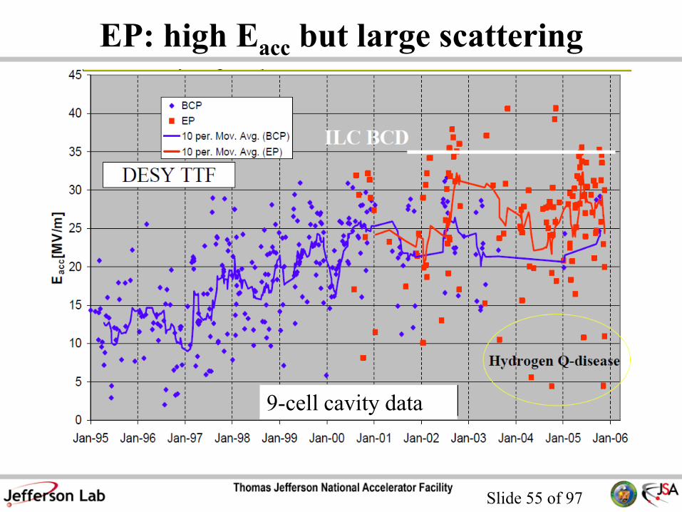
EP: high Eacc but large scattering
9-cell cavity data

Slide 56 of 97
Post-EP Cleaning Processes
• Ethanol Rinse (DESY)
• “Flash” BCP (10 mm) (DESY)
• “Flash” EP (3 mm, fresh acid, no re-circulation) (KEK)
• Ultrasonic Degreasing with Micro-90 and hot water (JLab)

Slide 57 of 97
Required Procedures for Qualifying SRF Cavities
• Degreasing surfaces to remove contaminates
• Chemical removal of exterior films incurred from welding
• Removal of damage layer of niobium from fabrication (150 mm)
• Removal of hydrogen from bulk Nb
• Mechanical tuning
• Chemical removal of internal surface for clean assembly (10-20 mm)
– Additional “cleaning” steps if Electropolishing (EP) is used
• High Pressure Rinsing (HPR) to remove particulates from interior
surfaces (incurred during chemistry and handling)
• Drying of cavity for assembly in clean room (reduce risk of particulate
adhesion and reduce wear on vacuum systems)
• Clean assembly
• Clean evacuation
• Low-temperature baking

Slide 58 of 97
High Pressure Rinsing (HPR)
ACCEL Instruments
• SRF cavities cleaning method to
remove particulates from
handling and contaminants after
chemistry from the inner surface
80 bar 0.02 mm

Slide 59 of 97
High Pressure Rinsing (HPR)

Slide 60 of 97
Particle Removal Mechanism
• Hydrodynamic model allows
estimating the shear stress t of the
water jet, which depends on flow
rate and pressure
• Particle removal by rolling if the
water shear stress is greater than a
critical shear stress t0, related to
the particle size, adhesion force
and surface roughness
2
0 22
44
ad
p p p
F H H
a a at

Slide 61 of 97
Adhesion forces:
• Coulomb
• Capillary
• Van der Waals
• Electrical double layer
Adhesion Forces
Q
-Q
h z
2
2
04
QF
d
Particle of diameter d
2F d : surface tension
2
7.2eV
16
dF
z
2dF
z
Example: 1 mm glass particle on water
1.4×10⁻⁷ N
4.5×10⁻⁷ N
3×10⁻⁸ N
1×10⁻⁸ N
Slide 62 of 97
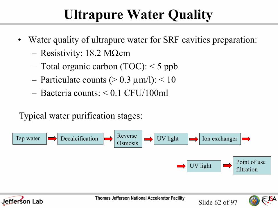
Ultrapure Water Quality
• Water quality of ultrapure water for SRF cavities preparation:
– Resistivity: 18.2 MWcm
– Total organic carbon (TOC): < 5 ppb
– Particulate counts (> 0.3 mm/l): < 10
– Bacteria counts: < 0.1 CFU/100ml
Typical water purification stages:
Tap water DecalcificationReverse
OsmosisUV light Ion exchanger
UV lightPoint of use
filtration

Slide 63 of 97
HPR QA
• Online monitoring of TOC, resistivity and particulate counts
• Collection of water from rinsed cavity for particulate analysis

Slide 64 of 97
HPR Systems
HPR stand inside the clean room
at JLab

Slide 65 of 97
HPR Systems
HPR stand inside the clean room
at DESY

Slide 66 of 97
HPR spray heads optimization
Very effective on irises Equator fill with water too high flow rate
• For a given pump displacement the nozzle opening diameter
and number of nozzles sets the system pressure and flow rate
• HPR spray heads needs to be optimized for a particular
cavity geometry!

Slide 67 of 97
HPR Jet Characterization
• Use a load cell to measure the force vs. distance of the water jet
F Q u 2 p
u
u = velocity
Q = flow
p = pressure
= density

Slide 68 of 97
Water Pressure vs. Distance
Pressure
(N/mm2)

Slide 69 of 97
Different HPR Configurations
• “Fan” jet allows greater surface
coverage compared to a standard round
jet
• HPR Duration: 3 - 12 h on 9-cell
cavity
• Cavity rotation: 2 – 20 rpm
• Wand movement: 8 – 50 mm/min
Slide 70 of 97
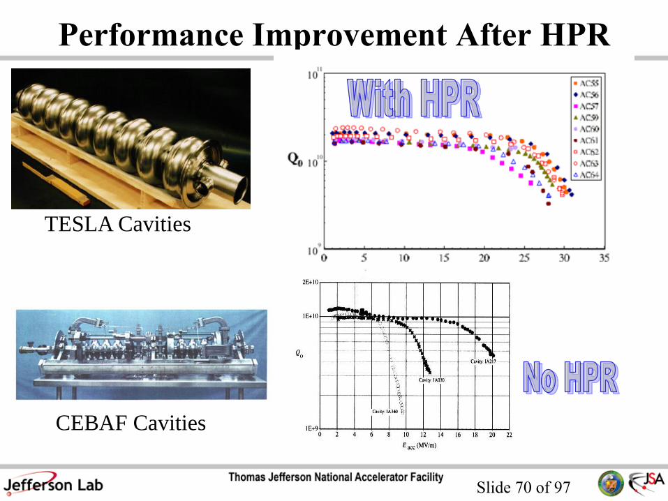
Performance Improvement After HPR
TESLA Cavities
CEBAF Cavities

Slide 71 of 97
HPR Issues
ISSUES:
• HPR systems are still not optimized
for the best surface cleaning
performance
• Surface left in a vulnerable state, wet
• This is still the best cleaning method against field emission!

Slide 72 of 97
Dry Ice Cleaning
• Complementary method to HPR, developed at DESY
• Liquid CO2 jet flowing through a nozzle and resulting in a
snow/gas mixture at a temperature of 194 K
• Removal of hydrocarbons and sub-micron particles while
keeping the surface dry by
– Thermal
– Mechanical
– Chemical
• Could be applied to a fully assembled
cavity mounted horizontally as a part of a
“cavity-string”
Slide 73 of 97
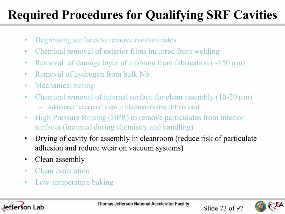
Required Procedures for Qualifying SRF Cavities
• Degreasing surfaces to remove contaminates
• Chemical removal of exterior films incurred from welding
• Removal of damage layer of niobium from fabrication (150 mm)
• Removal of hydrogen from bulk Nb
• Mechanical tuning
• Chemical removal of internal surface for clean assembly (10-20 mm)
– Additional “cleaning” steps if Electropolishing (EP) is used
• High Pressure Rinsing (HPR) to remove particulates from interior
surfaces (incurred during chemistry and handling)
• Drying of cavity for assembly in cleanroom (reduce risk of particulate
adhesion and reduce wear on vacuum systems)
• Clean assembly
• Clean evacuation
• Low-temperature baking

Slide 74 of 97
Particulates in Air
• Cleanroom technology is required to prevent airborne
particulates from settling on the surface of SRF cavities
Particle size (mm)

Slide 75 of 97
Cleanroom Technology
Cleanroom: a controlled environment in which all incoming
air, water and chemicals are filtered to meet high standards of
purity. Temperature, humidity and pressure are controlled, but
the key element is air filtrations.

Slide 76 of 97
Type of Cleanrooms
Unidirectional airflow type
Non-Unidirectional airflow type
Slide 77 of 97
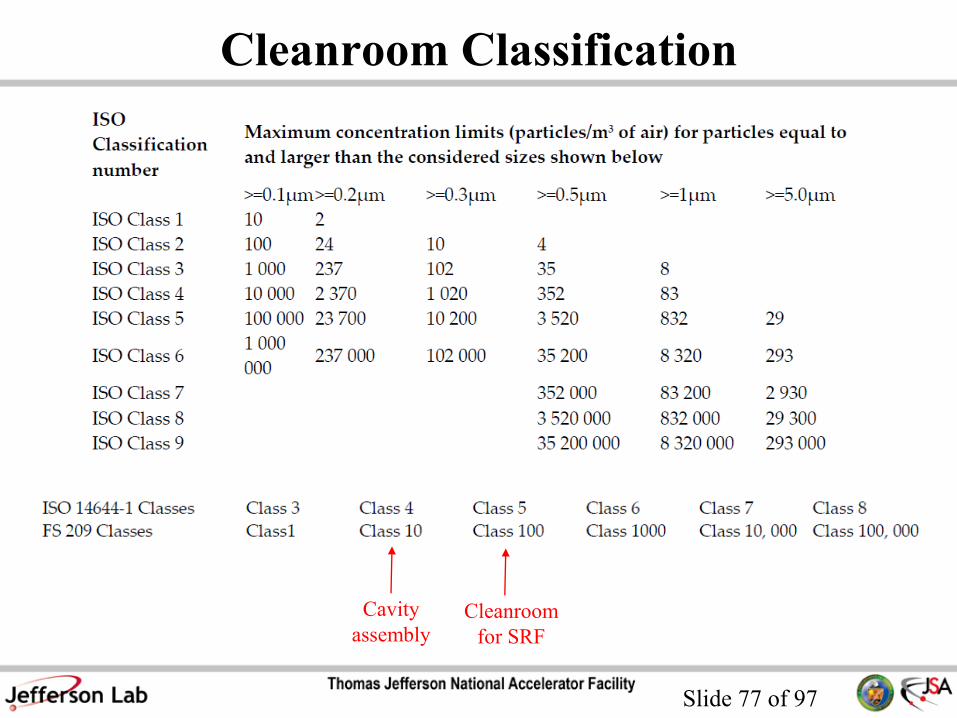
Cleanroom Classification
Cavity
assemblyCleanroom
for SRF

Slide 78 of 97
Particle Counters

Slide 79 of 97
People in Cleanrooms
• People are a major source of particulate contamination
inside a clean room through:
– Body Regenerative Processes - Skin flakes, oils, perspiration and
hair.
– Behavior - Rate of movement, sneezing and coughing.
– Attitude - Work habits and communication between workers.
Slide 80 of 97
Assembly: Vacuum Hardware
• The cavity strings have to be vacuum tight to a leak rate of
< 1 x10⁻¹⁰ torr l/sec
• The sealing gaskets and hardware have to be reliable and
particulate-free
• The clamping hardware should minimize the space needed
for connecting the beamlines

Slide 81 of 97
Assembly: Vacuum Hardware
• Present choice for ILC cavities:
diamond-shaped AlMg3 –gaskets +
NbTi flanges + bolts
Also used for SNS cavities
• Alternative:
radial wedge clamp, successfully used
for CEBAF upgrade cavities
• AlMg-Gasket
• Radial Wedge Clamp
Slide 82 of 97
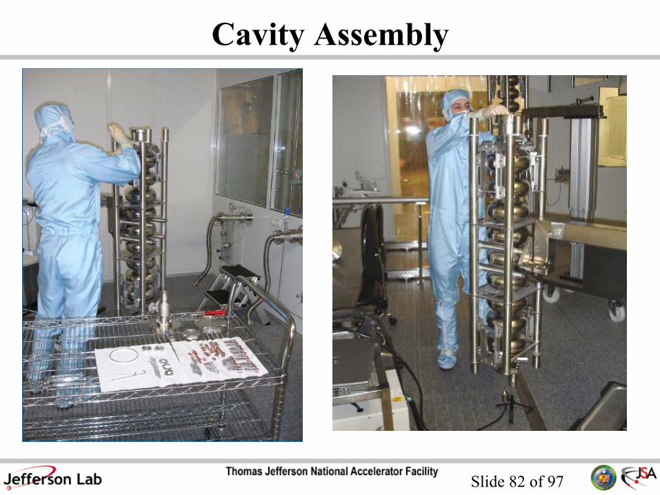
Cavity Assembly
Slide 83 of 97
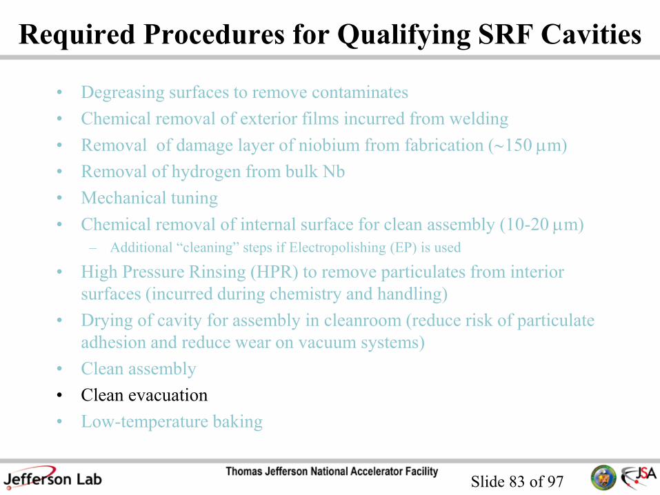
Required Procedures for Qualifying SRF Cavities
• Degreasing surfaces to remove contaminates
• Chemical removal of exterior films incurred from welding
• Removal of damage layer of niobium from fabrication (150 mm)
• Removal of hydrogen from bulk Nb
• Mechanical tuning
• Chemical removal of internal surface for clean assembly (10-20 mm)
– Additional “cleaning” steps if Electropolishing (EP) is used
• High Pressure Rinsing (HPR) to remove particulates from interior
surfaces (incurred during chemistry and handling)
• Drying of cavity for assembly in cleanroom (reduce risk of particulate
adhesion and reduce wear on vacuum systems)
• Clean assembly
• Clean evacuation
• Low-temperature baking

Slide 84 of 97
Clean Evacuation
• Oil-free pump stations with
leak check and residual gas
analyzer
• Laminar venting with pure,
particle filtered N2 or Ar

Slide 85 of 97
Clean Vacuum Systems
• “Dirty” or “contaminated”
(hydrocarbons, air leaks) vacuum
system can re-contaminate the
surface of a clean cavity!
Settling velocity for particles in air at
room temperature

Slide 86 of 97
Required Procedures for Qualifying SRF Cavities
• Degreasing surfaces to remove contaminates
• Chemical removal of exterior films incurred from welding
• Removal of damage layer of niobium from fabrication (150 mm)
• Removal of hydrogen from bulk Nb
• Mechanical tuning
• Chemical removal of internal surface for clean assembly (10-20 mm)
– Additional “cleaning” steps if Electropolishing (EP) is used
• High Pressure Rinsing (HPR) to remove particulates from interior
surfaces (incurred during chemistry and handling)
• Drying of cavity for assembly in cleanroom (reduce risk of particulate
adhesion and reduce wear on vacuum systems)
• Clean assembly
• Clean evacuation
• Low-temperature baking

Slide 87 of 97
Low-Temperature Baking
Hot N2 gas uniformly heats up the cavity
(JLab)
Infrared heaters heating the open cavity
inside the cleanroom (Saclay)

Slide 88 of 97
If Everything Works Well…
Ep 80 MV/m, Bp 170 mT can be achieved in the vertical test of
9-cell ILC cavities ( 1 m2 of Nb surface)
JLab DESY

Slide 89 of 97
Additional Steps for Cavity String
• Final mechanical tuning
• He-vessel welding
• Degreasing
• Final material removal (10-20 mm)
• Final HPR
• Horizontal assembly into cavity-string
• Evacuation of cavity string

Slide 90 of 97
Helium Vessel Welding

Slide 91 of 97
String Assembly
• A cavity string is assembled in a class 10 or class 100 clean room on an assembly bench over a period of several days after they have been qualified in a vertical or horizontal test.
• Prior to assembly, the cavities are high pressure rinsed for several hours, dried in a class 10 clean room, mounted onto the assembly bench and auxiliary parts are attached.
• The most critical part of the assembly is the interconnection between two cavities, monitored by particle counting

Slide 92 of 97
Example of Cavity Assembly Sequence
Cavities Are Moved to
Assembly Area via
Transfer Cart
Cavites Are
Placed Onto
String Assembly
Bench
Cavities Are
Mechanically
Aligned
Flange and
Blank Areas are
Cleaned
Bellows, Valves
Field Probes
and Flange
Blanks Are
Installed
Hardware is
Tightened
Couplers Are
Inserted
String is
Evacuated and
Leak Checked
String is
Removed From
Cleanroom
String is Baked
@120C 24hours
String is Ready
for Module
Completion
Cavities Are Dried In
Class 10
Staging Area
Cavity to Cavity
Connections
Are Completed
Coupler Flange
Area Is Cleaned
And Blanks
Removed

Slide 93 of 97
Coupler Insertion Procedure
Pre-align coupler to
cavity (including
rotation)
Remove cavity
flange cap
Clean cavity flangeRemove coupler
cap and clean
Insert seal ring
and then coupler
into cavity
Connect flange
hardware and
torque
Evacuate string
and leak check /
remove from
cleanroom

Slide 94 of 97
String Assembly
XFEL at DESY: 8
cavities per string
SNS g=0.61 string at JLab: 3
cavities per string

Slide 95 of 97
If Everything Works Well…
35 MV/m without field emission in operation with electron beam
is possible!
DESY
Slide 96 of 97
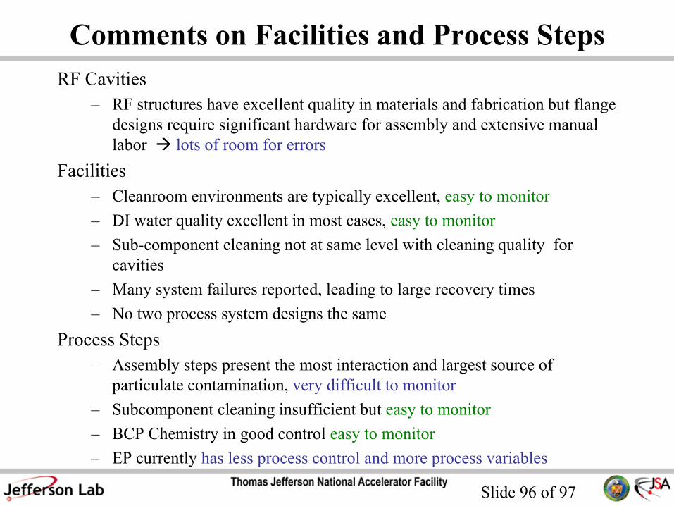
Comments on Facilities and Process Steps
RF Cavities
– RF structures have excellent quality in materials and fabrication but flange
designs require significant hardware for assembly and extensive manual
labor lots of room for errors
Facilities
– Cleanroom environments are typically excellent, easy to monitor
– DI water quality excellent in most cases, easy to monitor
– Sub-component cleaning not at same level with cleaning quality for
cavities
– Many system failures reported, leading to large recovery times
– No two process system designs the same
Process Steps
– Assembly steps present the most interaction and largest source of
particulate contamination, very difficult to monitor
– Subcomponent cleaning insufficient but easy to monitor
– BCP Chemistry in good control easy to monitor
– EP currently has less process control and more process variables
Slide 97 of 97
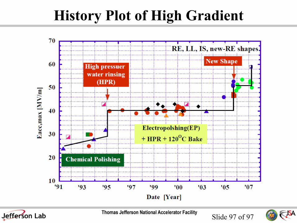
History Plot of High Gradient