GI-OBEXFarEast - mrt.tas.gov.au · PDF fileRunning/Cementing 30" Casing 5. ... A. Reporting...
72
\'l)t - I (7-( I . GI-OBEXFar East T/27P BARRAMUNDI-l OPERATIONS MANUAL August, 1999 Prepared by: KeUy Down Consultants Ply Ltd for GLOBEX Far East
Transcript of GI-OBEXFarEast - mrt.tas.gov.au · PDF fileRunning/Cementing 30" Casing 5. ... A. Reporting...

~IOA~~ \'l)t - I (7-( I
~~ ;;2~\'4~'\ .
GI-OBEXFar East
T/27P
BARRAMUNDI-l
OPERATIONS MANUAL
August, 1999
Prepared by: KeUy Down Consultants Ply Ltd
for GLOBEX Far East

TABLE OF CONTENTS
1. Rig Move/Anchoring
2. Pre-spud Preparation
3. Drilling 36" Hole
4. Running/Cementing 30" Casing
5. Drilling 17 1/2" Hole
6. Running/Cementing 133/8" Casing
7. Drilling 12 1/4" Hole
8. Running/Cementing 9 5/8" Casing
9. Plug and Abandonment
10 Drilling Problems
11 Leak-off Test Procedure
APPENDICES
A. Reporting Procedures/Forms
B. Time Analysis
C. Provisional Equipment Load-out List
D. Casing Diagrams
591002

fi91G03
1. RIG MOVE/ANCHORING
1.1 Notifications
1) The Operator is required to obtain permission from the Designated Authority tomove the rig to the drilling location in accordance with Clause 302 (3) of thePSLA-Schedule (minimum 7 days ahead ofthe intended move).
2) The OIM/Master will keep AMSA advised of the rig move and give them thefinal position when anchored up. The Operator should also notify the DA whenon location.
1.2 Operations
1) Prior to commencement of rig move/anchoring the OIM will conduct a meetingwith the workboat captainslrig superintendents/surveyors and Petroz DrillingSupervisor to discuss procedures and safety issues during the operation.
2) Extra AHSV crews may be required for the move in accordance with M047.
3) Extra marine personnel crews may be required for the move in accordance withM047.
4) The Barramundi-1 site survey does not indicate any anchoring hazards.
5) One additional anchor will be available offshore as contingency.
6) When running anchors, the daily drilling report should include for each anchor:
a) Time pennant passed to boatb) Anchor on Bottomc) Pre-tension load
7) Keep anchor tensions above normal drilling tension to prevent rig movementuntil the the BOP is landed.
8) A post-anchoring report is to be prepared by the OIMNessel Masters if anyabnormal conditions have occcurred.
9) A Positioning Report showing the final position, distance from intended location,anchoring diagram (showing the rig heading, anchor headings, tensions, lengthof chain and piggybacks used) is to be faxed to the Shore base when the rig isin position.
2. PRE-SPUD PREPARATION
While under tow or running anchors or rig has been ballasted through the transitionzone or as practical, the following items should be checked/prepared:
1) All BHA components have been inspected.
591004
2) Pressure test the BOPs, manifolds, valves etc in accordance with thepressures in the Drilling Programme.
3) Commence mixing mud as soon as the rig has been ballasted down past thetransition zone. Check with ballast control.
4) Dril-Quip wellhead equipment will be used (Dril-Quip engineer to be on board).
5) Inspect 30/20" float shoe for proper operation and absence of junk inside theshoe joint.
• 18 3/4" and 30" wellhead will have anti-rotation tabs.
Note: The 183/4" wellhead will be run with the 133/8" casing.
• Paint the 30" shoe and the 18 3/4" wellhead extension white.
• Clean and inspect 30" connectors.
• Paint the top 5m of the 30" wellhead with white bands at 1m apart.Number these bands to show distance from the top of wellhead.
• Measure and tally casing.
• Ensure pipe tally is checked independently by at least two people.
6) Measure PGB dimensions. Complete PGB Detail Form and fax to Shore baseoffice.
7) Ensure tide tables are available.
8) Install PGB in moonpool. PGBs will have lOft removable posts. Check that thelength will not interfere with the base of the BOP telescoping posts. Paintguideposts with numbering rings at the top with black paint.
9) Attach shear out assemblies to stop plates at bottom of posts. Use 10000 Ibshear pins. Attach shear out caps to end of guidelines as required.
10) Attach strops (made from geolograph Wire) around guidelines at 1 m from thepost base and tape around post. This is to facilitate the ROV in pulling out theguidelines from the posts if the guidelines are not properly cut (in the eventthe well is suspended).
11) Check Regan slope indicators (5 deg unit) are giving the correct reading - puttwo indicators side by side and observe angles are similar. Install first slopeindicator on PGB between SSTV guide wires. Install second slope indicator onthe opposite side.
PGBs should have two prefabricated trays at 180 deg made for this.

591005
12) If sea conditions permit, makeup and hang off 30" casing into PGB.
• Carry out JSA.
• Make up 30" wellhead running tool to 1 stand of HWDP and rack back.
• 30" casing will consist of: Wellhead, Cross-over joint, Intermediate andshoe joint as per diagram.
• 2 sets of 30" elevators will be required to run the 30" casing.
• Skid back PGB and cover wellhead.
13) Make up circulating head to a single of HWDP and layout.
14) Make up 18 3/4" wellhead hang off tool and rack back.
15) As soon as practical, jump ROV to inspect seabed. This may have to be donewith pipe in the water if guidance is required.
Note: If visibility is poor or high currents are present, advise DrillingSuperintendent. Consideration will be given to running a TGB
16) Ensure a TGB is available on board for contingency purposes.
17) Makeup 183/4" wellhead RIT(with DP pup as required) into 183/4" wellhead.
18) Pick up BHA as required.

591006
3. DRILLING 36in HOLE
A) Potential Hazards
• Ledges that can prevent casing entry.• Locating hole due to poor visibility• PGB inclination/excessive wellhead wear
B) General Operating Practices
1) The hole will be flushed with seawater at the seabed to clear away any buildup of suspended gel. This will allow better visibility of the hole for casing entry.
2) Two hole markers are to be placed prior to POH.
3) To minimise the difficulty in finding the hole, the ROV is to take a fix on thehole and markers and to remain stationary on bottom until the casing isstabbed in. This will allow the entry point to be permanently located on thevideo monitor.
C) Operational Procedures
1) Carry out JSA prior to picking up BHA.
2) Pick up and rack back 5 stands HWDP.
3) RIH with the following BHA:
26" bit Type IADC 1119 1/2" Pony Drill Collar36" Hole Opener Security Custom 4 - + Totco ring1 x 9 1/2" Drill Collar36" Stabiliser Welded blade3 x 9 1/2" Drill CollarsCrossover 7 5/8" Reg Pin x 6 5/8" Reg Box.3 x 8" Drill collarsCrossover 65/8" Reg Pin x 4 1/2" IF Box.HWDP
3) Paint bit and hole-opener white.
4) Paint white mark on drill collar to denote TD of 36" hole. This will allowconfirmation of TD with the ROV.
Note: The 30" casing is to be landed on bottom. Maximum stick-up forthe 30" wellhead is 2.0m.
5) With pumps just ticking over, tag seabed and note water depth. ROV toobserve (note if any currents).

591007
6) Check if string is vertical in moonpool.
Spud well at slack current conditions.
• Spud well with 500 gpm, 50-60 rpm, 3-5000lb WOB and drill with lowparameters for the first 5-10m or until firmed up.
• Thereafter use 1000-1100gpm, 50-100rpm, O-IOOOOlb WOB.
• At hard bands, do not increase WOB (to prevent ledging). Reducef10wrate to minimise hole washout.
• The seawater should be treated with Noxygen and the. pipe sluggedwith Amitec when POH. Refer to mud programme for details.
• Sweep hole with 50bbl Hi-Vis pill every 5-IOm depending on ROP. Spot100 bbl Hi-Vis pill at connection.
7) Drill to required TO. Circulate out 100bbl Hi-Vis pill. Make wiper trip. Do notpull bit above seabed. RIll to TO.
8) At TO circulate out a 100 bbl Hi-Vis pill and spot 200bbl prehydrated gel.
9) Drop Totco survey prior to POH.
• If gel cover obscures hole, POH to 1m below seabed. Circulate withseawater for 2-3 min. to flush away the gel above the hole and allowbetter visibility during casing entry.
• Prior to POH, the ROV is to position 2 hole markers 2-3m from the hole diagonally opposite each other.
• The ROV is to confirm the white mark on drillcollar if visibility allows.
• The ROV is also to obtain a location fix of the hole relative to the markersand to remain on bottom. This will allow the hole to be permanentlylocated on the video monitor.
• The ROV should attempt to catch a small sample of drill cuttings fromseabed for geological studies.
10) Check and grade biUholeopener.

591D08
4. RUNNING/CEMENTING 30" CASING
1) Skid PGB/casing to underneath rotary table.
2) Run two singles of drill-pipe below the running tool.
3) Makeup running tool to wellhead
4) Pick PGB up off beams. Note the slope indicator readings.
5) Run the casing on HWDP. Fill the casing at the splash zone with seawaterusing the top drive.
6) Stroke out motion compensator before casing enters the hole.
• ROV should already be on bottom to observe entry.
7) Land casing on bottom and slack off casing weight. Compensate runningstring.
Note:lf slope indicator reading is more than 1.0 degrees, attemptto decrease angle by picking up casing or moving rig asappropriate. If angle is still more than 1.0 degrees consult withShore Base.
8) Mark pipe at rotary. ROV to check height of wellhead above seabed and PGBorientation. Record distance to top of wellhead.
9) Ensure all guidelines are in tension.
10) Rig up cement hose. Pump 50 bbl seawater. Pressure test lines. Mix andpump cement in accordance with the Drilling Programme and final laboratorytests from Halliburton.
• Cement slurry samples are to be collected during the cement job.
• Casing setting depth must be held constant during cementing. If mark onpipe at rotary starts to float up, slack off weight to maintain position. Allowfor tide movement.
• Displace cement to within 5m of the shoe. Observe cement returns withROV.
Note:Do not stop pumping cement until calculated volume has beenpumped even if cement is observed at the seabed.
11) When cement is in place, check for backflow. If float shoe does not holdattempt to rock float. If unsuccessful, displace any excess bleed back. Holdpressure until cement sets.

591009
12) Check slope indicator. If angle is more than 1.0 degree, hold casing tension todecrease angle and hold until cement sets.
13) Release running tool. POH. Strap out for exact distance to wellhead. Layoutrunning tool.
14) Settide marker.
15) Complete the casing/cementing report and forward to Shore base.
16) On Daily Drilling Report, state if cement returns were visible, PGB angle andwellhead stickup.

591010
5. DRILLING 17 1/2" HOLE
A) Well Design Considerations
This section will be drilled riserless. Returns will be to the seabed.
B) Operations Procedyres
1) RIH with the following 17 1/2" BHA:
17 1/2" Bit IADC 1152 x 9 1/2" Drill Collars17 1/2" Stabiliser3 x 9 1/2" Drill CollarsCross-over9 x 8" Drill CollarsDrilling Jar2 x 8" Drill CollarsCrossover15xHWDPRun corrosion coupon in first/secondstand of drill-pipe.Recommended Drilling Parameters:WOB: 5000 IbRPM: 30 (Surface)Flow Rate: 1100 - 1200 gpm
2) Tag cement with pumps on and drill out shoetrack.
Note: Whether or not full returns are obtained, corrosion inhibitionshould be maintained. The seawater or mud should be treated withNoxygen and the pipe slugged when POH.
3) Drill ahead with 50bbl HI-Vis pills each half stand or stand down depending onROP. Ream connections as necessary. Spot 50-7Sbbl Hi-Vis pill onconnections.
4) Drill 17 1/2" hole to 875m +/- section TD (10m rathole for casing).
5) Circulate the well clean with 100bbl Hi-vis pill.
6) Displace the hole to prehydrated gel.
7) POH and strap out.
8) Rig up and run casing
591011
6. RUNNING/CEMENTING 133/8" CASING
1) Pre - casing running checks:
• Casing laid out, numbered, tallied, drifted, threads inspected. Check 10 ofcasing (every 5 joints) to obtain average 10 for displacement calculations.
Note: the 13 3/8" casing will be run below the 18 3/4" housing.
• Ensure pipe tally is checked independently by at least 2 people.
• HWOP landing string drifted to 2.625in on last trip out.
• Running tool, plug launch mandrel and single of S135 OP to be drifted to2.625in.
• Space out plugs below the RT/housing to ensure within the 133/8" casing.
• Attach centraliser in between two stop collars at mid-joint.
• Ensure adequate pit volume is available for mud returns while runningcasing/cementing.
• Run 1 threadlocked joint between float shoe/collar joint. Threadlock up tofloat collar connection. Check float collar and float shoe are functional.
2) Carry out JSA prior to running casing.
• The 350T side door elevator will be used to run the entire 13 3/8" casingstring.
• Hand slips to be used for the entire string.
• Note that the link tilt needs to be attached to the casing bails for ease ofhandling the casing.
• Rig up packer fill up/circulating device (if needed).
• Run shoe joint. Fill with mud to check floats.
• Run float collar joint. Fill with mud to check floats.
• Casing to be filled every joint as it is run in the hole.
• Pit volume to be monitored while running casing.
Note: Makeup last 4 joints to maximum possible torque to minimisecasing backing out during casing cutting at PIA.
591012
3) After running casing, makeup to 183/4" housing and RIH with HWDP.
4) After making up top drive cement head, land casing with motion compensatorsupporting all but 5-10,000 Ib of landing string weight. Check indexmeasurement.
5) Break circulation. Circulate 100bbi seawater or mud (dependent on losses). Donot exceed 800psi or 10bbl/min.
6) Pressure test lines. Pump 20 bbl drillwater.
7) Drop ball and shear out bottom plug with +/- 1200psi.
8) Mix and pump cement in accordance with the Drilling Programme and finallaboratory tests from Halliburton.
• Collect cement slurry samples while mixing cement.
• Leave 2bbl of cement on top of rubber plugs to allow for ease ofdrilling out.
9) Drop dart and shear out top plug with +/- 2500psi with total of 10bbl seawater.Slow pumps down to 1bbl/min to observe shear out. Rig pumps to displaceremaining volume of seawater.
10) Slow down pumps prior to bumping. Bump plug to 1000psi over final slowpump pressure. Hold for 5mins. If plug does not bump, pump extra volumeequal to half the shoetrack volume.
11) Bleed back and check for flow.
12) Run BOPs in accordance with Sedco procedure and pressure test to thepressures specified in the Drilling Programme.
13) Complete the casing/cementing report and forward to the Shore base. Reportfinal cirCUlating pressure, percentage returns and estimated TOC.

591013
7. DRILLING 12 114" HOLE
A) Well Design Considerations
The 12 114" hole will be drilled to 1777m total depth. A PDC bit will be used.
9 5/8" casing will be run if required for production testing.
The mud weight should be maintained as low as possible. Normal formationpressures are expected. Mud losses may occur in the Eastern View CoalMeasures and Icm will be available if needed. The Demons Bluff formationcontains a relatively reactive and dispersive claystone. The main objectiveAKCUPHPA mud will be used.
B) General Operating Practices
1) Hard shut in technique to be used for well control.
2) Wiper trips to be made as needed.
3) Ream connections as required.
4) SCRs - to be taken at start of shift, change of mud weight, change of bitnozzles/BHA, extended length drilled.
5) Flow checks - Do prior to POH, hole fill/gain has deviated, when in doubt,when bit is inside shoe, before HWDP enters BOP.
6) A complete mud check is to be taken twice a day.
7) The torque limiter is to be set to the maximum level to allow for maximumtorsional energy to be transmitted. This is particularly critical with PDC bits formaximising ROP.
8) Check fishing grapples are available for all tools run.
C) Operational Procedures
1) RIH with the following 12 1/4" BHA:
12114" PDC Bit8" Monel1 x 8" Drill Collars9 x 8" Drill CollarsDrilling Jar2 x 8" Drill CollarsCrossover15 x HWDPRun corrosion coupon

591014
1) Drill cement with seawater.
2) Drill to shoe. Displace to mud.
3) Cleanout rathole.
4) Drill 3m of new hole. Circulate until mud is sufficiently balanced.
5) Perform LOT (expected 1.6sg MWE +1-). Record SCRs.
6) Drill ahead. Do not use high RPMs until all of roller reamers are below theshoe.
7) Ream connections as necessary.
8) Drill to 12 1/4" section TD at 1777m +1- (10m rathole for casing).
9) Circulate bottoms up.
10) Run Logs.
11) Run 9 5/8" casing for testing or plug and abandon as directed.

591G15
8. RUNNING/CEMENTING 9 5/8" CASING (IF REQUIRED FOR TESTING)
1) Pre - casing running checks:
• Casing laid out, numbered, tallied, drifted, threads inspected. Check 10 ofcasing (every 5 joints) to obtain average 10 for displacement calculations.
• Ensure pipe tally is checked independently by at least 2 people.
• HWOP landing string drifted to 2.625in on last trip out.
• Running tool, plug launch mandrel and single of 5135 OP to be drifted to2.625in.
• The casing hanger lock ring is to be left in.
• The float shoe joint will be sent to rig with a pre-installed solid aluminiumcentraliser. Only I centraliser will be run.
• Ensure adequate pit volume is available for mud returns while runningcasing/cementing.
• Run 1 threadlocked joint between float shoe/collar joint. Threadlock up tofloat collar connection. Check float collar and float shoe are functional.
2) Carry out J5A prior to running casing.
• The 350T side door elevator will be used to run the entire casing string.
• Hand slips to be used for the entire string.
• Rig up Tam packer fill up/circulating device (if supplied).
• Run shoe joint. Fill with mud to check floats.
• Run float collar joint. Fill with mud to check floats.
• Casing to be filled every joint as it is run in the hole.
• Pit volume to be monitored while running casing. Run casing as fast aspossible without inducing losses (check surge pressures).
Note: Makeup last 6 joints to maximum possible torque to minimisecasing backing out during casing cutting at PIA.
3) After running casing make up hanger with wellhead spacer and RIH withHWOP.
4) After making up top drive cement head, land casing with motion compensatorsupporting all but 5-10,000 Ib of landing string. Check index measurement.

591016
5) Break circulation - circulate casing volume. Do not exceed 800psi or10bbllmin.
6) Pressure test lines. Pump 20 bbl drillwater.
6) Drop ball and shear out bottom plug with +/- 1200psi.
7) Mix and pump cement in accordance with the Drilling Programme and finallaboratory tests from Halliburton.
• Collect cement slurry samples during mixing.
• Leave 1 -2bbl cement above rubber plugs to allow for ease of drillingout the rubber plugs.
8) Drop dart and shear out top plug with +/- 2500psi with total of 10bbl seawater.Slow pumps down to 1bbl/min to observe shear out. Rig pumps to displaceremaining volume of seawater.
9) Slow down pumps prior to bumping. Bump plug to 1000psi over final slowpump pressure. Hold for 5mins. If plug does not bump, pump extra volumeequal to half the shoetrack volume.
10) Bleed back and check for flow.
11) Set seal assembly
12) Pressure test seal assembly to the pressure specified in the DrillingProgramme.
13) RIH and set 95/8" wear bushing.
14) Pressure BOPs to the pressures specified in the Drilling Programme.
15) Complete the casing/cementing report and forward to Shore base. Report finalcirculating pressure, percentage returns and estimated TOC.

591lJ17
9. WELL ABANDONMENT PROGRAMME
Actual plug depths will be advised after logs have been evaluated.
1. RIH with OEDP with stinger to xxxxm. Circulate bottoms up. Spot 8 cU.m (50bbl) hi-vis pill.
2. Pull back to xxxxm and set cement plug across casing shoe from xxxx - xxxxmwith Class G cement at 1.92 sg.
3. Pull back above toe and circulate clean. WOC. Tag plug with 5000kg andpressure test to 2500 psi.
4. Cut and recover 9 5/8" (if run) at xxxm.
5. Mix and pump surface cement plug from xxx - xxxm.
6. Pull BOPs.
7. Cut and recover 18 3/4"and 30" wellheads and PGB.
8. Conduct seabed survey with ROV.

591018
10 DRILLING PROBLEMS
10.1 Hole Problems
Hole problems most likely to be encountered are:
(a) Mud rings, balling of stabilisers, DC assembly and bit, when drilling long shalesections.
(b) Unstable hole, due to sloughing or spalling clays/shales causing caving.
(c) Wallsticking and losses due to high mud weight, sticking due to key-seats,hole bridging or packing off.
10.1.1 Troublesome Formations
These formations may contain large proportions of claystones and unconsolidatedclays and shales. When coming into contact with water, these "GUMBO" clays swelland slough into the hole. To minimise this sloughing, mud weights can sometimes beused which are high enough to counteract this effect.
The hydration and subsequent swelling of Gumbo clays will be reduced and retardedby the use of inhibitive drilling fluids.
• potassium/sodium chloride: restrict hydration;• polymers, polyacrylamides: encapsulation of clay particles.
Older shales can have a more brittle nature and are often subjected to mechanicalstresses and overpressures, causing spalling which results in caving of the hole. Thistype of hole instability can be prevented by a high mud gradient and low fluid loss ofthe mud.
The importance of solids control in these parts of the hole cannot be overemphasised, and therefore all available solids removal equipment (shakers,desanders, desilters and centrifuges) should be used and be maintained atmaximum efficiency. Smallest possible screen sizes should be used on shakers,without incurring excessive mud losses because of screen flooding.
The mud viscosity depends on the number and size (surface area) of suspendedparticles. Bentonite clays hydrate very easily, resulting in an increased surface areaand inter-action between particles, and thus in a rapid increase of the viscosity. Theultimate effect of the particle interaction is the recombination into conglomerates "mud rings". Therefore, the following points should be noted when drillinglworkingthrough these sections of the hole:
1. Obtain maximum annular velocities by using maximum possible circulatingrates, combined with optimum lifting capacity of the mud and optimum flowprofile.
2. SAPP can be effective in breaking these rings.

591019
3. Increase the frequency of checktrips. Drill with reduced RPM if conditionspermit.
4. When reaming large intervals, use minimum practical number of drillcollarsand use minimum stabilisers.
5. If necessary, restrict the penetration rate in order to limit the generation ofsolids, to such a rate that the solids can be efficiently removed.
6. Allow adequate circulation time to clean the hole prior to pulling out for around trip
7. Always shut down the pumps slowly and gradually, to avoid aggravating holeproblems.
8. If problems are experienced with severe gas cutting (or trip gas), especially incase of deep holes and small size drill strings, it may be necessary to circulatebottoms up after a round trip prior to drilling ahead. This avoids confusion indetermining the difference between trip and influx gas.
10.1.2 Tight Hole
Usually the causes or contributing factors can be recognised as follows:
1. Drilling through long sensitive shale sections.
2. Mud properties not up to standard, ie. shale inhibition, water loss, density,lubricity, rheology and lifting capacity, etc.
3. Insufficient annular velocity and insufficient circulating times to effect optimumhole cleaning and/or optimum mud conditioning and treatment.
4. Insufficient solids removal in the mechanical mud treating equipment, ie.shakers, desanders, desilters, etc.
5. Insufficient attention to mounting problems.
10.1.3 Causes and Discussion
The causes may be: insufficient inhibition - mud weight - lubricity - or hole cleaning.All these factors are important parameters, and comparison should be madebetween wells without any problems and which parameters were changed leading tothe deterioration of the hole.
Tight hole problems start in most cases whilst coming out of the hole. It occurssometimes where fresh hole has been drilled, or formations above reacting tochanging hole conditions. Constant or spot-like overpull is experienced in excess ofthe normal when coming out of the hole.
The overpull could be the result of balling up of stabilisers and drillcollars by

591020
formation not removed, or from squeezing formations.
It is important to realise that this situation could lead to stuck pipe. To prevent this,the Drilling Supervisor should make certain that free movement, rotation andcirculation is maintained at all times.
Ensure that the hole below, when pulling out (or above when running in), is in a goodshape so as to be able to go back there to regain rotation and/or circulation.
Balling up of drillcollars and stabilisers under continued high overpulls results in lossof circulation, swabbing and finally sticking the string. In such circumstances, runback to a good part of the hole, condition the mUd, add lubricants and maybe weightup the mud.
Try again to pull out (or run it) if it is decided that nothing more can be done.
It is not possible to lay down hard rules, which will successfUlly cover the wide varietyof sensitive areas.
The following standing instructions should be adhered to at all times:
1. Establish normal drag, up and down, prior to and whilst tripping.
2. DO NOT continually overpull unless in spots only. In case the overpull iscontinuous and/or increasing immediately, install the kelly, circulate andREAM DOWN a few singles first. Condition the mud and strongly consideradding lubrication to the system. Try again to come out of the hole and do nothesitate to wait too long before installing the key and rotate/circulate out ofthe hole single by single.
3. Ensure free movement of the string below the tight hole area at all times.
4. Contact Sydney Office if no improvement can be achieved when trying to pullout again.
Raising the mud weight over and above the weight normally used in the areais a last remedy to apply and should be confirmed by Sydney Office.
10.1.4 Stuck Pipe
General
Most stuck pipe problems not mentioned above can be attributed to differentialpressure sticking, or what is more commonly referred to as "wall sticking". Theprimary indication of wall sticking is very obvious, I.e. the pipe sticks while motionlessand thereafter cannot be rotated, and while full circulation at normal pump pressurecan be maintained. Generally, these conditions occur while making connections orduring a trip. It should be noted at this point that no drilled hole is absolutely vertical.This being the case, exerting a tremendous pulling force on the drill string would tendto align the pipe vertically and introduce the possibility of causing sticking above the

C:°1r.'<)~viJ_J':".1.
original stuck point.
This sticking can take place in any interval where the hole is deviated even a smallamount from the vertical. This is the reason to stick to the standard order pull slowlyeven when the hole is in good shape. Many preventive measures can be taken tominimise wall sticking.
The possibility of wall sticking is lessened by altering mud properties: decreasing themud weight to lower the differential pressure is one method, but this is not alwayspossible. Another method is by lessening the contact area between the pipe and wallcake. This depends upon cake thickness. For this reason, low filtration rates andminimum solids concentration are desirable. Materials that reduce the friction factorbetween the pipe and mud solids are also of value in minimising wall stuck pipe.Chemical oil emulsion muds, extreme pressure lubricants (bit lube) and detergentsare all beneficial.
10.1.5 Methods of Freeing Stuck Pipe
In spite of all precautions, stuck pipe still occurs. The problem then is to free the pipeor fish by one of several methods:
1. Working it loose, washing over, connecting over shot.
2. Reduction of hydrostatic pressure by spotting a column of fluid lighter thanthe mud in use, such as water or oil.
3. Application of a drill-stem test tool. In the case of a full string in the hole, pipemust be backed of f first. The test tool is run in with open ended drill pipebelow it. The string is latched on and when the DST tool is opened, thedifferential pressure is relieved, freeing the pipe.
4. Spotting of various fluids around the pipe, such as oil or oil base mud, invertoil muds, saturated salt water, acid, and special surface liquids (PIPELAX)added to crude oil, or diesel oil. For weighted mud, PIPELAX can be mixedwith oil base muds corresponding to the weight of the mud in the hole. Thiswould prevent the tendency of a short fluid column of less density floating upthrough the heavier drilling fluid.
After the fluid is spotted, the pipe must be worked. The best method is to put the pipeunder compression by slacking off 4.5 Tonne (10,000 lbs). below the weight of thepipe and then applying torque by turning the string at drill floor Yo turn per 30Cm (1,000ft). Release torque and pick up the 4.5 Tonne (10,000 Ibs). Repeat this cycle asnecessary.
Most of the time, the pipe will come free on the compression cycle. It should bepointed out that working the string in tension or hoisting with over pull, the indicatedweight of the string could cause the pipe to become stuck further up the hole due towall sticking, key seat or dog legs.
1. Have mud in good shape.

591022
2. Pull slowly out of the hole.
3. Reciprocate string continuously.
4. Do not circulate at one spot.
4. Prepare to make connections as fast as possible.
10.1.6 Drill String Back-off Procedure Job Preparation
Job Preparation
1. String should be worked as long as possible prior to rigging up toprevent the stuck point from moving up.
2. Obtain the following data:
(a) Weight of string before sticking, as read on Martin Deckerweight indicator (check if weight of kelly was included in thisreading or not).
(b) 1.0., 0.0. and weight of drill pipe or tubing (thread coupled).
(c) 1.0., 0.0. and weight of drill collars.
(d) Hole data: bit size, total depth, casing size and weight, depth ofcasing shoe.
(e) Depth of drill pipe, drill collars, drilling bit.
(f) Depth ofjar, safety joint. overshot. Check if 1.0. is smallerthan1.0. of pipe.
(g) Hole deviation.
3. Make a sketch of the string showing the above information.
5. Establish back-off depth based on Free-Point indicatormeasurements on or stretch test.
6. Calculate required left hand torque and pUll:
LEFT HAND TORQUE:Back-off Depth
Drill Pipe: From
Turns per 300m(1 .000ft)
0-1 ,220m (0-4,OOOft) 1/4-%
1,220 - 2,745m (4,OOO-9,OOOft) 1/21

PULL:
over
TUbing: From
over
2,745m (9,000ft)
o-1 ,830m (O-6,000ft)
1,830 m (6,0000)
591023
3/4 -1
3/4 -1
Hook load to be applied is equal to Martin Decker reading prior to sticking (2a)minusbuoyant weight of fish to be left in hole.
If Martin Decker reading is not available, the hook load to be applied is calculated asthe buoyant weight of the pipe from the surface to back-off depth.
6. Check that tong and slip dies are sharp and of correct size to hold pipe
7. If tongs are used to apply torque, check that snub or dead lines and jerk linesare in good condition, snub or dead lines should be double checked.
NB: NEVER REMOVE SNUB OR DEAD LINES
8. Tighten tool joints (especially for tubing), giving 30% more right hand torquethan in the left hand torque calculated at step 5 (if not done previously).
Method for applying torque with slips:
(a) Make pull equal to value found in Step 5.
(b) Set pipe in slips.
(c) Tie slip handles with soft line.
(d) Apply required right hand torque.
(e) Let torque come out, counting number of turns.(f) Repeat, applying torque until all torque which has been put in comes
outagain.
Note: This method in practice does not allow the right hand torque to betransferred to the stuck-point. Consultation with Sydney Office is advised ifthe correct procedure for transferral is unfamiliar.
9. Lock hook and elevators on travelling block.
10. Ascertain that mud level in pipe is not considerably lower than level in

591024
annulus.
11. Select proper sling for attaching upper sheave (equal to twice the breakingstrength of the cable). Hoist upper sheave in derrick and attach with sling toderrick structure. Do not hand sheave on travelling block or on sandline.
10.1.7 Preparation ofthe String
(To be done immediately before running back-off shot in the hole).
1. Pull on pipe with value calculated in point 5.
2. Set pipe in slips. lower travelling block until elevators are well clear oftooljoint (leave elevators closed around drillpipe).
3. Tie slip handles together with piece of soft line.
4. Apply left hand torque: number of turns as calculated in point 5.
5. Release torque slowly and count how many turns come out.
6. If fewer turns come out than have been put in, repeat steps 4 and 5 untilnumber of turns coming out =number of turns put in.
7. Re-apply left hand torque as in Step 4 and hold with rotary lock (or tongs).
10.1.8 Back-off Operation
1. Position back-off shot opposite collar by using CCL.
2. Check that derrick-floor is cleared of all personnel.
3. Fire back-off shot.
4. After detonation of the string shot, the connection is often found to have spuncompletely free. In some cases, however, the connection may only havepartially back-off. To complete the back-off:
(a) Apply up to half the original left hand torque used, noting the ammeteror rotary torque gauge for indications of back-off. If back-off isindicated, continue until complete.
(b) If the torque is not lost, it is usually an indication that the hook load isincorrect. Correct this by applying half the original left hand torque withthe rotary and holding it with the rig tongs. Pull the slips and adjust thehook load. When the load is correct, the torque will be released.
5. Pull up pipe a few feet to confirm that the pipe is free. Make certain that noresidual torque remains when pipe is picked up. The eCl may be used to

591025
check that the string has backedoff at the desired point.
If the back-off is not successful, the string shot may be increased by 2-3strands of primer cord over the Electric Loggers recommended charge for asecond attempt.
10.2 Lost Circulation
10.2.1 General
Lost circulation or lost returns may be defined as the loss of whole mud to theformation. The loss may vary from seepage of a few bblslhour to complete loss ofreturns. Lost circulation occurs when the pressure of the mud column exceeds theformation pressure. A properly planned casing program and good drilling practicescan reduce the occurrence of lost circulation.
(a) Unconsolidated, Coarsely Permeable Formations
Unconsolidated formations of sand or pea gravel are usually found close tothe surface, but may be found at any depth. Normally these are drilled(sometimes without returns) and cased off without difficulty. Controlled drillingrates may minimise this type of loss in larger holes.
(b) Cavernous and Vugular Formations
Cavemous or honeycombed zones are normally found in limestone anddolomite formations. This type of loss is usually predictable in a given areabecause it occurs in definite formations which are easily traceable. In thistype of loss, abnormally rough drilling may precede the loss, and the bit maydrop from a few inches to several feet. Returns will usually cease suddenlyand completely. This type of loss is the most difficult to cure. Blind drillingusually is the most feasible solution if it can be done safely, although foamand air drilling have been applied.
(c) Fissures and/or FracturesAny type of rock may have natural fractures. Fractures may be the result ofjointing, fissuring or faulting. Loss in this type formation requires a bridgingagent to seal the fractures.
(d) Mechanically induced Fractures
A formation (normally a shale zone) which did not have a loss of circulationwhen penetrated may have fractures induced during drilling operations.Excess pressure may break down these weakened zones already drilled andcause loss of circulation. Excess pressures can result from solids build-upfrom fast penetration rates, turbulent annular velocities, spudding the bit whilecirculating, pressuring up on a mud ring, and fast tripping. The loss is usuallysudden and complete. Induced fractures should be suspected if the sameinterval has been drilled in offset wells without loss.

591026
10.2.2 Procedure for Lost Circulation Prevention
1. Keep mud density to the minimum required to control pressure plus providesome safety margin. Pressure which will cause lost circulation (fracturepressure) at the shoe is determined through leak off tests.
2. In areas of known lost circulation, keep gel strengths and viscosity to aminimum.
3. Break circulation slowly. To minimise pressure surges, start pump whilepicking up pipe and rotating. N.B. especially after trip.
4. Use reduced pump pressure when drilling through known lost circulationzones in order to reduce bit pressure drop or utilise larger nozzles to reducebit pressure drop.
5. Time drill known lost circulation zones to prevent loading the annulus withexcess cuttings.
6. Avoid excess trips through lost circulation zones.
7. Avoid fast tripping.
8. Avoid pre-treating with lost circulation materials when possible. An LCM pill isoften all that is required, and If properly spotted, will be just as effective astreating the whole system, while having the added advantage of keepingmechanical solids control equipment operable.
9. Drill with no returns through lost circulation zone when possible beforetreating for lost circulation, as the high cost of lost circulation treatments,coupled with bridging characteristics of materials and heating characteristicsof formations make consolidation of all losses economically and operationallydesirable. Drilling 'blind" should only be carried out with approval of DrillingManager.
10.2.3 Lost Circulation Whilst Drilling
The following procedure should be followed when surface losses become apparent:
(a) Check all surface equipment for open valves (HCR) on flare line etc.
(b) Slow pump rate to see if circulation returns.
(c) Determine actual losses at specific pump rates.
(d) Reduce mud weights if possible.

Notes
1. Minimise pressure surges by careful down-hole drill string handling. This canoften reduce lost circulation problems.
2. Leave out stabilisers, in order to avoid swabbing out LCM pills when movingthe pipe, if it is anticipated that these pills will have to be spotted.
3. It is usual practice to leave the jets out of bits if LCM spotting is anticipated.
10.2.4 Locating Loss Zones
Successful treatment of lost circulation depends upon accurately locating the intervalin which fluids are lost. Unless caverns are encountered, most losses will be foundabove the bottom of the hole and may, in fact, be at or just below the bottom of thelast casing shoe. Loss of time and materials will result if the loss zone is not located,especially if any type of plugs are to be set. Various methods are available, egtemperature surveys, and will be advised from main office.
10.2.5 Lost Circulation Materials
Two types of plugging materials are available:
(a) Non-acid soluble plugging materials:
ego Mica, Mudfibre, Cellophane, Walnut shells, Peat.These materials are suitable for combating mud losses in a nonproductive formation. Many of these are available in various grinds forthe differing applications.
(b) Acid soluble plugging materials:
ego Calcium carbonate.Above materials are usually applied to cure losses in productive zones,but should be treated with care.
10.2.6 Types of Losses and Procedure for Treatment
1. Light (Seepage) Losses
This is usually 0.5 to 3 barrels per hour loss indicated when flow does notreturn immediately after connections. The first step to cure would be to pull upand wait or to drill ahead with partial returns if the next casing point is comingup. Attempts to cure with flakes of cellophane or mica can help. "Kwikseal" ora similar product at 10-30 Iblbbl is effective. Any good water loss controlagent will help as an effective filter cake should be built quite quickly.
2. Moderate Losses

591028
These are indicated by- drop in pit level. Mica fine (20 Ib/bbl) with a nutplugmedium to coarse (10-20 Ib/bbl) to begin building the bridging material iseffective. Squeezing by applying backpressure is effective and usually a goodfilter cake bUilding mud will remedy the situation. The concentrations of thevarious products used is usually determined on site by factors such aspumpability and screen blinding.
3. Complete Losses
This is indicated by total loss of flow in flowline and immediate drop in pitlevel. Pump pressure will usually drop also. Many methods are available toovercome the problem. If LCM additions cannot control the losses, then moredrastic procedures are required.
(a) "Flochek" Procedure
1. General
Halliburtons product, "Flochek', has been used successfully in Australianland operations.
Rig up cement pump truck and rig pumps to the floor using a "te&" manifold.The success of the operation depends on being able to alternate easily andquickly between rig and cement truck. The pump truck should be tied in totwo storage tanks of at least 50 bbls each, and a fresh water supply to theunit supplied. A cutting blade is required to mix chemicals into the storagetanks.
The following is a typical treatment and may have to be repeated severaltimes.
2. Solution Preparation - note: adequate fluid is prepared to allow for tankresidual
SOLUTION A:
SOLUTION B:
SOLUTION C:
Calcium Chloride solution - Mix 1,750 Ibs CaCI2 in 50 bblsof fresh water giving a 10% solution. Use rig mud tanks.
"Flochek" Solution. Prepare 50 bbls of solution using 25bbls fresh water and 25 bbls "Flochek A". Use storagetank.
Cement Mixwater. Using the other storage tankcompletely dissolve 78 Ibs of THIXSET A in 25 bbls freshwater followed by 40 Ibs THIXSET B. Thoroughly mix andrecirculate tank to ensure complete dissolution.

591029
3. Procedure
• R.I.H. open ended drill pipe to suspected lost circulation zone: keepaccurate check of pipe in hole.
Pump 20 bbls of Solution A;Pump 10 bbls of fresh water;Pump 20 bbls of Solution B;Pump 10 bbls of fresh water;Pump 20 bbls of Solution A;Pump 10 bbls of fresh water;Pump 20 bbls of Solution B;Pump 10 bbls of fresh water.
Mix and pump 30 bbls of cement slurry130 sx (94Ibs) neat Class "A" + 19.5 bbls SOLUTION C.
SlurryWtYieldWater Requirement
14.8 ppg1.32 ftlsk6.3 gal/sk
Displace cement to give balanced cement plug.
Pull back to top of cement and circulate with mud.
• Backpressure (up to 20psi) can be applied at any time returns are seenprovided solution A is past the bottom of the drill pipe.
(b) Diesel Oil- Bentonite - Cement Squeeze
DOBC squeezes can be applied to lost circulation problems that cannot beremedied with any of the above. A DOBC slurry is prepared simply by mixingwith a jet mixer, approximately 20 sx of cement and 20 sx of gel per 10 bbls ofdiesel oil. Each 10 bbls of diesel oil prepares 14 bbls of slurry.
Note: All pumping and mixing equipment through which the slurry will passmust be free of water. When displacing the slurry down the drill pipe, the slurryshould be immediately preceded by 10 bbls of alcohol followed by 20 bbls ofdiesel oil and the slurry followed by 10 bbls of alcohol, then 10 bbls of diesel oil.Any slurry left in the bottom of the suction tank should be dumped. If the slurryis allowed to contact water, the bentonite and cement will hydrate and causethe slurry to begin to set.
DOBC squeezes have a number of significant advantages over neat cementsqueezes. Rather than setting to a rigid mass, a DOBC slurry forms a tough,plastic-like plug which can deform as drilling proceeds. This reduces thelikelihood of re losing circulation from a nonrigid thief zone. With a DOBCsqueeze, there is not the danger of the squeeze job failing to seal the lost zonebecause of mud contamination, although contamination should be avoided.

5911)30
PROCEDURE FOR PLUGGING LOST CIRCULATION ZONES WITH DIESELOIL BENTONITE CEMENT SLURRY
(a)lf possible, drill without returns through all the lost circulation zone.
(b)lf (a) not possible, pull out of hole. Go in hole with open-end drillpipe.
(c)Set bottom of open-end drill pipe approximately 10-15m (30-Soft)above lost circulation zone and rig up pump truck.
(d)Determine volume required and mix slurry as per above ratios.
(e)Pump in 10 bbls alcohol, then 20 bbls diesel oil ahead ofthe slurry.
(f)Displace slurry down the drill pipe and follow with 10 bbls of alcohol,then 10 bbls diesel oil.
(g)When the 20 bbls cushion of diesel oil reaches the bottom of theopen-end drill pipe, close rams and start pumping mud into theannulus with rig pump while the slurry is being pumped down thedrill pipe. Pumping rates should be controlled so that the ratio of slurryvolume to mud is 2 to 1.
(h)Displace one-half the slurry into the formation at a fast pumping rate.The drill pipe may occasionally be reciprocated slowly to watch for anyindication that the slurry might be moving up the annulus. If the weightindicator shows any increased drag, break the connections and raisethe pipe until it is free. Make connection and continue displacement.Since the slurry has no pumping time limitations inside the pipe, thereneed be no concern over short shut-down period.
(I)Displace the next quarter of Volume of slurry (and mud) at one-halfthe rate used in Step )g).
G)Displace the remaining quarter volume of slurry at a rate of one-halfof the rate used in Step (I). Attempt hesitation squeeze in order toobtain a pressure bUild-up. Approximately 1 bbl of slurry should be leftin the drill pipe at the completion of the squeeze. Do not attempt toreverse circulate, because mud will contact the slurry and "gel up"inside the drill pipe.
(k)POH and wait on gelation of minimum of eight hours before drillingout.
(c) Barite Plug - Pressure
In normal pressure control, a very critical situation can arise when a well begins

591031
kicking and losing circulation at the same time. Increasing the mud density to controlthe high pressure 'zone will only complicate the problem of lost circulation. When theabnormally-pressured zone lies below the thief zone, barite-plugging can be used tocontrol the well.
An extremely heavy, high water-loss slurry is required for this technique. Bantesettling and deposition will form a solid plug in the open hole, weighing down andsealing off the high pressure zone. In addition, the high filter loss results in rapiddehydration, bridging the hole and further aiding in sealing off the pressured zone.Once a barite plug is in place, normal steps for regaining circulation may be takenwith relative safety. Barite plugs weighting from 18-24 ppg may be prepared usingbarite, fresh water, phosphate (SAPP) and caustic soda.
No viscosifiers are used and care must be taken to prevent contamination of theslurry with mud because rapid settling of the barite, once it is spotted, is anecessity. The plug should be rapidly pumped, set as close to bottom as possible,and then the drill pipe withdrawn to avoid sticking.
Coarse grind barites are not recommended because they will not stay suspendedlong enough to spot. Brackish or salt water should not be used because the settlingrate is drastically reduced.
A cementing truck should be used to mix the slurry. Barite is mixed with fresh watercontaining 1 Iblbbl sodium acid pyro-phosphate (SAPP) and 0.2 Iblbbl caustic soda.The lines from the cementing truck can be connected directly to the drill pipe througha plug valve.
To minimise the possibility of stuck pipe, the derrickman should be in the derrick andthe elevators ready to come out of the hole immediately after pumping is completed.
Procedure for Setting Plug:
1. Determine how many feet of plug in the open hole is desired. 120-150m (400500ft) is usually adequate.
2. Choose a slurry density (higher density weights are preferable).
3. Calculate bbls of slurry required and add 20 bbls.
4. Calculate amounts of barite, phosphate, caustic soda and fresh waterneeded.
S. Batch mix the slurry to an even consistency and pump it down the drill pipe.(Spot close to bottom and be ready to come out qUickly).
6. Underdisplace by 5 bbls with mUd.
7. Immediately pull up above the plug. Circulate until gas dissipates. Proceedwith normal operations.

The Following Seven Points are Important
1. Too heavy a slurry will prevent bridging from occurring.
2. A minimum of 6 bpm rate down the drill pipe must be maintained duringmixing or displacement or the barite will settle out in the drill pipe and canplug the bit.
3. The SAPP/water ratio is critical to obtain the best fluid loss for bridging.
4. You must use fresh water and the system should have a pH of 9.
5. A back pressure should be maintained during placement and stripping up outof the plug or more gas can enter the well bore and destroy the effectivenessofthe plug.
6. Bulk barite is preferred so that 40 or more sacks can be mixed per minute.
7. A barite plug should not be followed immediately with cement. Firstly, see if itis effective and then run the cement.
Note: Constant consultation with Sydney Office would be required in this operation.
10.3 Fishing
10.3.1 General Practices
The standard fishing assembly is as follows:
OVERSHOT-JARS-DCs-ACCELERATOR-HWDP-DP-KELLY
The amount of D.C. run depends on what is left in the hole and what isavailable on the rig. To get maximum effect from jarring, however, the sameamount of D.C. as left in the hole should be run on top of the jars.If insufficient drillcollars are available, an Accelerator can be run on top of thedrillcollars. The number of drill collars can then be substantially reduced check with Sydney Office.
Do not run a safety joint. Experience has proven that jarring on a safety jointfreezes this tool, and makes the tool useless. Also, it would not be possible touse a stringshot as no left-hand torque could be applied to the string.
The one exception to this rule is when a washover string is run. A full openingsafety joint (drive joint made for jarring) is run below the standard fishingassembly so that intemal cutters may be run when the washover string sticksand has to be backed off; on top of the W.O.S., a junk sub can be installed.When using a washover string, always use 5 - 10% diesel oil in the mud toreduce friction. When a twist-off occurs and penetration rates are high,circulate the hole clean first before pulling out of the hole.

5911)33
Prior to connecting to the fish, circulate as required.
Always use a spiral grapple in preference to a basket grapple, wheneverpossible.
Do not use an overshot with oversize guide when a bent single is used.
If the overshot has engaged the fish and the backlash is out of the string,lower part of the string weight onto the over shot (±40% of fish string weight).Then pick up fish 1.5 to 2.5m (5 to 8ft) and drop string 0.6 to 1.2m (2 to 4ft)and catch it in the brake to make sure of a firm grip. Then POH. If an overshotis run after the fish has been milled over, always run an extension to avoidcatching the fish on the milled part.
When fishing in an oversize hole, use a bent single (1 straight single belowbent single if reqUired) to facilitate screwing back on.
10.3.2 Jarring
Heavy pulling and jarring must be done with the kelly added to the string. Onthose rare occasions where this is not possible, the elevator latch should besecured by means of a rope or a chain, provided the tooljoint above theelevator has a square shoulder. Never use an elevator for jarring if the tooljoints have an 180 shoulder taper.
Remove the kelly spinner (if extemally mounted) if possible, before anyjarring with the kelly is done to avoid damage and parts coming loose.
When sustained jarring is carried out, drilling line must be slipped at regularintervals to avoid permanent damage to the wireline at the crossover points.The time interval between slipping depends on the intensity of the jarring.
Regularly check the derrick and lifting equipment for loose bolts, etc.Prior to jarring, always mark the string position at the rotary table.
The proper jarring method is to allow the jar to trip first with the requiredoverpull before further overpull is applied.
NOTE:The use of 2 jars in tandem gives an additional insurance andincreases the frequency of strokes which can be given in a certain time.Never, however, trip the upper jar until it is certain that the lower jar hastripped first. (Bleed some oil from the lower jar at surface to let it trip first.) Ifin doubt, do not trip any of the jars, but re-set them first.
10.3.3 Use of Junk, Reverse Circulating Junk Baskets
When using junk baskets, it is important to core approximately 15 cms (6) andthen pick up the string to allow junk on the side of the basket to fall into thepilot hole, so that it can be recovered when coring is continued. Maximumlength of core depends on the size of the basket, but is usually 0.4 - 0.6m (1%
591034
to 2ft). Run a stabiliser on top of the basket to aid in dislodging junk stuck inthe wall (undersized baskets only).
Use 1.3-2.7 Tonne (3-6,000 Ibs) WOB, 45 RPM and circulate at 250-300GPM.
If a basket is run, make sure that, after it is made up, the catcher fingers canrotate freely. Also check that the correct size basket is used for the junk in thehole.
10.3.4 Spears
The standard assembly for a spear is as follows:
Spear - Spearstop - Fishing jar (18" stroke) - hydraulic jar - DC - OP - Kelly.
The spear must be equipped with a pack-off rubber when circulation isrequired. Also a stop-ring or spear stop should be used (spaced as required),which will prevent stabbing too deep and will also make the release easierand prevents re-engaging deeper down. It is also needed to reset the jars.The distance from the stop ring to both 178mm (7") and 244mm (9") spears is1.2-1 .8m (4-6ft).
When engaging the spear, always make sure that a tooljoint is at a workabledistance above the rotary table. This may require using pup joints.
If the spear has to be released and knocking down on the spear does not freeit, then install the surface jar (1 .22m - 4 ft stroke) below the kelly and jar downon the spear.
When a tap is used, DO run a safety joint, but leave out the jar.
NOTE: Check the spear stop 0.0. when it is run in open hole, and use thestops only if hole conditions permit. Avoid using a full-circle spear. If doneanyway, don't use a spear stop.
10.3.5 Lost S.W.S. Bullets
If bullets are lost in the hole, run in with a rockbit and junk sub, rotate andcirculate along the places where the bullets were lost to attempt to dislodgethe bullets from the wall of the hole. When on bottom, drill a few feet. If nosignificant torque is encountered, continue as per program.
If drilling indicates that there is junk on bottom, pull out and run a basket tofish for junk.
When it is reported that bullets are lost in the hole after an Electric Loggingrun and more runs have still to be made, Electric Loggers can do so,provided the guns are not lowered below the spots where bullets were lost.

591035
10.3.6 Fishing Tools - Standard Wellsite Inventory
The following tools should be on site as a minimum.
• Overshots and oversized guides with grapples, baskets and extension substo catch all sizes of tools in hole.
• Hydraulic jars to match the D.C. string in use.
• Reverse or straight circulating baskets for hole size required.
• Junk subs for required hole sizes.
• Fishing tools to catch any contractors' tools.
Optional are safety joints, tapertaps, accelerators to match jars, bumper andsurface jars, casing spears with stop-rings and pack off assemblies.
Have a junk mill on site to match production hole size.
10.4 Drilling Coal
When drilling COAL, the Drilling Supervisor should ensure that the followingprocedures are followed:
1. Never attempt to drill more than five (5) ft of Coal without circulating.The circulating period does not have to be an extended one, 2 to 3minutes is adequate. It is merely to give your drilling fluid a chance tomove the mass of cuttings up hole. After circulating, slowly pull upabove the Coal seam and attempt to run slowly back to bottom. Ifthere is no fill on bottom, drill ahead another 2m (Sft), repeating theprocedure and being sure to pull up above the first seam penetrated.
2. When working Coal seams, it is essential that the bit is pulled up soslowly that no swab pressure is exerted on the formation and reamedback to bottom in the same manner so that no surge pressures arecreated in the well bore. Both surge and swab pressures will causepressure sensitive seams to slough or, in severe cases, literallyexplode into the well bore, increasing the problem dramatically.
3. If the Coal seams are stable and it is possible to drill ahead, maintain aclose watch on the shale shaker. If the majority of your cuttings areCoal and your penetration rate indicates a formation other than Coal,then a Coal seam has sloughed up hole and Sydney Office shouldthen be notified.
4. Under no circumstances, attempt to pull up through or jar through aCoal seam. The time lost circulating is very inexpensive compared to afishing job.

591036
5. Back reaming up through a Coal seam should also be viewed as ahigh risk operation, with the potential of an expensive fishing job beingweighted against the cost of circulating for a few hours.
6. Slow trip times while running drill collars and BHA past Coal seams isessential to the stability of the seams.
591037
11 FORMATION INTEGRITY TESTS (FIT)
Purpose
Formation Integrity Tests (FIT) are run to determine the strength of the formationexposed by the well bore and to check the integrity of the cement job. The results areused to calculate; the maximum equivalent mud weight that can be used to safelycontrol formation pressure without losing circulation, maximum allowable casingpressure and kick tolerance.
11.1 Frequency
FIT's will be conducted:
• After drilling 2m of new hole beyond the rat hole below the casing shoe forcasing sizes 340mm (13-3/8") through to T.D. unless specified otherwise inthe Drilling Program.
• At other times, at the discretion of the well management team.
11.2 Casing Pressure Test Procedure
The casing is to be pressure tested as follows:
1. Test before drilling out the cement and shoe track by closing the blind/shearrams and pumping at 1/4 6PM down the choke line with the cement unit.
2. Measure the volume and plot at v.. bbl increments vs pressure until therequired test pressure is reached.
3. Shut down pump and hold pressure until convinced the casing is not leaking.
4. Bleed back and record volume recovered. Should be same as volumepumped.
5. Plot pressure vs volume data and use to establish a minimum volume line forthe FIT to follow.
11.3 Formation Integrity Test
• For tests at the casing shoe drill 2m of new formation. Circulate bottoms up toensure that new formation has been penetrated and that a uniform knownmud weight is in the hole.
• Pull bit into the casing to avoid problems with stuck pipe. Do not slug pipe.
• Close the BOP rams and hang off drillpipe.

591038
• Rig up cement unit to pump down the drillpipe and circulate the line to the drillnoor with mud. Pressure test the line.
• Choose an appropriate range for the pressure chart recorder. Monitor thepressures and volumes and plot pressure against volume pumped on the FITdata sheet during the FIT.
• Pump down the drillpipe at a constant rate that has been selected so that theslope of the pressure volume plot is parallel to the minimum volume lineconstructed preViously on the FIT data sheet. The pump rate can vary from 14bbl/min to 1-Y2 bbl/min where the filtration rate is high or a larger amount ofopen hole is exposed.
• The maximum surface pressure should go as high as the predicted fracturegradient for the area and should not exceed the equipment or casingspecifications.
• The plot should be a straight line until leak-off when it should curve and flattenout. Pick the lead-off pressure as the last point on the established straightline.
• After a satisfactory FIT has occurred or the estimated fracture pressure hasbeen reached, stop pumping immediately to minimise fracturing and note theinstantaneous pressure drop on the graph. Record and plot the pressureevery minute for 5 minutes or as necessary to establish stable readings.
• Bleed off the pump pressure and record the bleed-back volume; the volumeshould approximate the volume pumped.
• Complete the data sheet showing the equivalent mud weight calculations andtransmit to operations office.
• Prepare a maximum allowable choke pressure versus mud weight graph andpost is at the choke control unit. Take into consideration the pressure dropthrough the choke line especially if the maximum allowable choke pressure islow. This can be done by using the kill line pressure.
11.4 FIT Calculations
The pressure recorded at leak-off is used to calculate the formation fracture pressure (interms of equivalent mud weight) as follows:
EMW= MW + Leak-off PressureCsg. Seat Depth x Conversion Constant

Example:
Data: 340mm (13-3/8\") casing set at 914m (3000')TO = 920m (3020')Mud Wt. = 1.08 SC (9.0 PPG)Leak-off Pressure = 3795 kPa (550 psi)Conversion Constant 1.0 SC = 9.81 kPa/m
591/)39
EMW= 1.08 SG 3795 kPa914m x 9.81
= 1.5 SG
Example:
Data:(ImperialUnits)
340mm (13-3/8") casing set at 914m (3000')
TO = 920m (3020')Mud Wt. = 1.08 SC (9.0 PPG)Leak-off Pressure = 3795 kPa (550 psi)Conversion Constant 1.0 PPG = 0.052 psi/ft
EMW=
=
9.0 PPG +
12.5 PPG
50psi3000'x .052

APPENDIX A - REPORTING PROCEDURES
591040

591041
APPENDIX A - REPORTING PROCEDURES
1.0 General
Standard fonnat reports will be used for all drilling operations as detailed in thissection.
All reporting to the Government and Partners will be done by Globex.
2.0. Drilling and Operations Reports
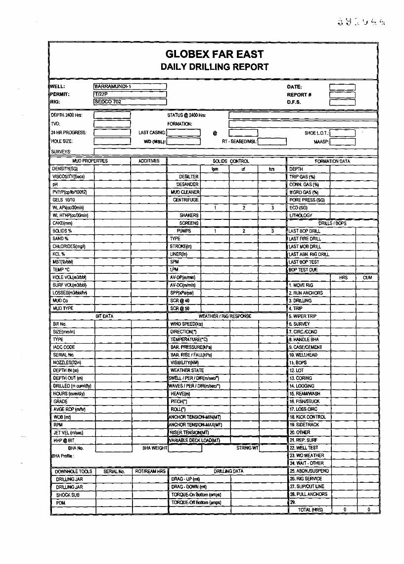
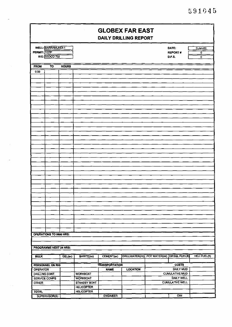
2.1 Daily Drilling Report (ddr-bar.xls)
The Daily Drilling Report is in Excel fonnat.
Units to be used will be as specified on the report fonn, nominally 'oilfield units' withdepth measurements in metres and mud weights in Specific Gravity.
Reporting will be from midnight to midnight with an update to 0600 hours.
Time analysis should be consistent with the lADC fonn (any disagreement with theContractor on time breakdown should be resolved before completion of the IADCfonn). See also Appendix A for definitions oftime allocation.
Bulk stocks to be recorded on this fonn.
'Personnel on Rig' to reflect number of persons on the Rig site at midnight.
2.2 Afternoon Report (pm-rep.doc)
The Afternoon Report will be a briefupdate from 0600 hours to 1500 hours.
2.3 Costing (pngcost.xls)
A daily total of drilling costs will be maintained and added to the DDR prior to issue.This will be done in Sydney. An Excel spread sheet has been prepared to track costs.The spread sheet provides a daily, weekly and cumulative summary.
2.4 Operational Instructions (instr.doc)
All instructions to the drilling contractor at the Rig site are to be made in writing sothere is no ambiguity as to the Supervisor's requirements. This is particularlyimportant when there is only one Supervisor on site. This fonnat should also be usedby the Drilling Superintendent confinning instructions to the Drilling Supervisor.
2.5 Programme Amendment (pgamend.fax)
Departure from the approved Drilling Programme is not pennitted without pennissionfrom Globex and the MRT (if required). Any amendment will be advised in writing to

the Drilling Superintendent for on-passing to the Drilling Supervisor. The amendmentmay be initiated by KDC or Globex but shall not be acted upon without the writtenapproval ofGlobex.
2.6 Incident Report (inc-rpt.doc)
All operational incidents (eg stuck pipe, well kicks, tool failure etc) shall bedocumented as to cause, consequence and action taken together withrecommendations for prevention or improvement.
2.7 Rig Weekly Safety Inspection Report
The Drilling Contractor's forms will be used.
2.8 Accident Reporting
The Drilling Contractor's and Globex procedures will be used.
2.9 Drilling Fluids Report
The Drilling Fluids Engineer will provide a Daily Report including materialsconsumption. He will be responsible for mud stock control and advising the DrillingSupervisor of requirements.
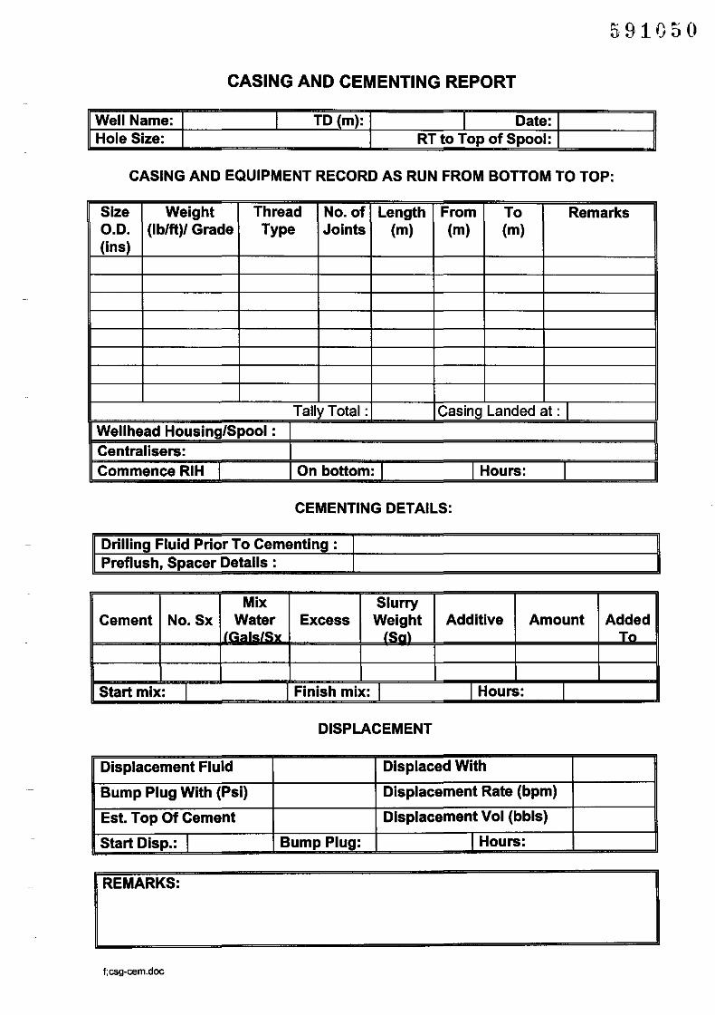
2.10 Casing and Cementing Report (csg-cem.doc)
This report will be used in its entirety in the Well Completion Report.
The Cementing Service Engineer will provide an after job report including materialsconsumption. He will be responsible for cementing materials and accessories stockcontrol and advising the Drilling Supervisor ofrequirements.
2.11 Casing Seat Pressure Integrity Test (lot.xls)
This report will be used in its entirety in the Well Completion Report.
2.12 Trip SheetlKick Control
The Drilling Contractor's Well Control Procedures will be followed and theContractor's standard forms will be used.
2.13 Bit Record ( bit-rec.doc)
This report will be used in its entirety in the Well Completion Report.
2.14Bottom Hole Assembly Record (bha-rec.doc)
This report will be used in its entirety in the Well Completion Report. A summary ofthe bha only is required (ie bit - bit sub - 12 1/4" NBS etc) as the DDR will includedimensional data.

2.15 Deviation Record (dev-rec.doc)
This report will be used in its entirety in the Well Completion Report.
2.16 Rental Tools Inventory
Format to be finalised.
2.17 Materials Inventory
Format to be finalised.
frpt-proc.doc!grI21-8-99
591043
GLOBEX FAR EASTDAILY DRILLING REPORT
WELL: IBARRAMUND~l I DATE: I IPERMIT: IT127P I REPORT' I IRIG: ISEDC0702 I D.F.S. I I
OEPTH 2400 HIS: I I STATUS@2400H'"
00: I I FOIlMATION:
24 HR PROGRESS: I I LAST CASING:I I @ I I SHOE L.O.T.:I IHOlE SIZE; I I WD(MSLI:! I RT - SEABEO!MSL:I I MMsp:1 ISURVEYS: I
MUO PROPERTIES ADDITIVES SOLIDS CONTROL FORMATION DATA
DENSITY(SG) Ipm uf hIS DEPTH
VISCOSITY(Secs) DESILTER TRIPGAS(%)
pH DESANDER CONN. GAS ('Ii»
PVIYp(cpllbll00ft2) MUD CLEANER B'GRD GAS (%)
GELS 10110 CENTRIFUGE PORE PRESS (SG)
WL API(CCI3Omin) 1 2 3 ECD(SG)
WL HTHp(ccJ3Omin) SHAKERS LITHOLOGY
CAKE(mm) SCREENS DRILLS I BOPS
SOLIDS % PUMPS 1 2 3 LAST BOP DRILL
SAND % TYPE LAST FIRE DRILL
CHLORIDES(mgll) STR()I(E(ln) LAST MOB DRILL
KCL% L1NER~n) LAST ABN. RIG DRILL
MBT(lbIbIiI) SPM LAST BOP TEST
TEMP"C LPM BOP TEST DUE
HOLE VOL(m3.W) AV-DP(mlmin) HRS CUM
SURF VOL(m3.W) AV-DC(mlmin) 1. MOVE RIG
LOSSES(m3lbbllh~ SPP(kPalpsll 2. RUN ANCHORS
MUD Co SCR@40 3.DRIWNG
MUD TYPE SCR@50 4. TRIP
BIT DATA WEATHER I RIG RESPONSE 5. 1MPER TRIP
BIT No. 1MND SPEED(kIS) S SURVEY
SIZE(mmfln) DIRECTION(, 7. CIRC.ICOND
TYPE TEMPERATURE("q 8. HANDLE BHA
IADCCODE BAR. PRESSURE(kPa) 9. CASEICEMENT
SERIAL No. BAR. RISE I FAwkPa) 10. WELLHEAD
NOZZLES(3~n) VISIBILlTY(NM) 11. BOPS
DEPTH IN (m) WEATHER STATE 12LDT
DEPTH OUT (m) ~LL I PER I DIR(m/sac/') 13, CORING
DRILLED (m cuml<l1y) ~AVES I PER I DIR(mJsacr) 14. LOGGING
HOURS (cumldly) HEAVE(m) 15. REAMlWASH
GRADE PITCH(") 18. FISHISTUCK
AVGE ROP (mlhrj ROW") 17, LOSS CIRC
WOB(ml) NCHOR TENSION-MIN(MT) 18 KICK CONTROL
RPM NCHOR TENSION-MAX(MT) 19. SIDETRACK
JET VEL (m/sac) RISER TENSION(MT) ZO. OTHER
HHP@BIT ARIABLE DECK lDAD(MT) 21. REP. SURF
BHA No. BHAWEIGHT I STRINGWT 22, WELL TEST
BHA Profile : 23. WO WEATHER
24. WAIT - OTHER
DOWNHOlE TOOLS SER1ALNo. ROTIREAM HRS DRILLING DATA 25. ABDN,/SUSPEND
DRIWNGJAR DRAG· UP (mt) 26, RIG SERVlCE
DRIWNGJAR DRAG - DOWN (ml) 27. SLiP/CUT LINE
SHOCK SUB TORQlJE-Dn Bottom (amps) 28. PULL ANCHORS
PDM TORQlJE-Dlf Bottom (amps) 29.
TOTAL (HRS) 0 a
591045
GLOBEX FAR EASTDAILY DRILLING REPORT
WELL,IBARRAMUNDI-1 I DATE, Q-Jan-oD
PERMm\T!27P I REPORT. 0
RIG:lsEDCO 702 I D.F.S. 0
FROM TO HOURS
0:00
OPERATIONS TO 0800 HRS,
PROGRAMME NEXT 24 HRS,
BULK I GEL(sx) BARlnE(sx) I CEMENT(sx) IDRILLWATER(mt) POT WATER(ml) /DIESEL FUEL(ilf HEll FUEL(~)
I I I I
PERSONNEL ON RIG TRANSPORTATION COSTS
OPERATOR NAME LOCATION DAlLY MUD
DRILLING CONT. WORKBOAT CUMULATIVE MUD
SERVICE COMPS WORKBOAT DAlLY WELL
OTHER STANDBY BOAT CUMULATIVE WELL
HELlCOPnER
TOTAlL HELICOPTER
SUPERVISOR(S) ENGINEER I OIM

To: .
cc: .
Well: Permit:
Date:
Depth:
Operational Summary since 06:00 hrs*.
Mud Data: Weight:Weight I I Viscosity I PVNP I I Chlorides I
Comments/Requirements:
From: .Drilling Supervisor
(*Include relevant geological data)
f:pm-rep.doclgr

~ Barracuda Limited
591047
INCIDENT REPORT II
Report No: Date: Prepared By:Well: Operator: Rig:INCIDENT
WELL DATA/OPERATIONS PRECEEDING INCIDENT
EVALUATION OF INCIDENT (Cause, were procedures/orders followed?,
REMEDIAL WORK CARRIED OUT
RECOMMENDATIONS
f.mc-rept.doclgr
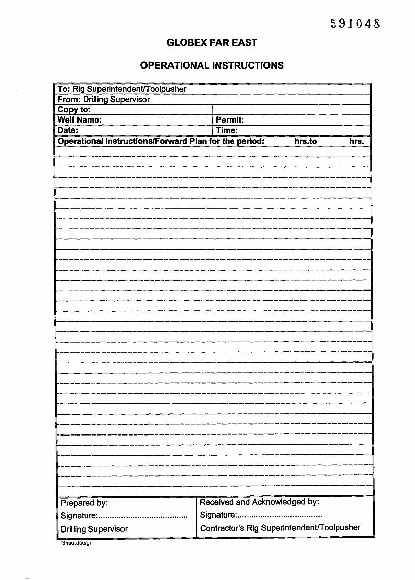
591048GLOBEX FAR EAST
OPERATIONAL INSTRUCTIONS
To: Rig SuperintendenUToolpusherFrom: Drilling SupervisorCopy to:Well Name: Permit:Date: Time:OperationallnstructionslForward Plan for the period: hrs.to hrs.
------------------------------------------------------------------------------------------------------------------------
------------------------------------------------------------------------------------------------------------------------
-----------------------------------------------------------e------------------------------------------------------------
.
------------------------------------------------------------------------------------------------------------------------
------------------------------------------------------------------------------------------------------------------------
-------------------------------------------------------------------------------------------------------------------------
------------------------------------------------------------------------------------------------------------------------
-------------------------------------------------------------------------------------------------------------------------
Prepared by:
Signature: .
Drilling Supervisor
t.instr.docJgr
Received and Acknowledged by:
Signature: .
Contractor's Rig SuperintendenUToolpusher

KELL YDOWN CONSULTANTS Pty LtdA.C.N.OO8 152 207
591049
Mall:PO Box 573, SI Leonard.N.S.W., 2065, AUSTRALIA
51, Chandos SlraelSI Leonard.
N.S.W., 2065, AUSTRALIA
Tel: 61-2-9901-3422 Mobil.:(01e) 446-440 Fax: 61-2-9901-3635
No. of Pages inc!. this pageDATE: Ref:
FACSIMILE HEADER
TO:
ATTN:
FAX No:FROM:
SUBJECT: Amendment to Drilling Programme
Well Name: Amendment No:Amendment:
Prepared by: Approved by:
Signature: ................................ Signature: ..................................On behalf of Globex Far East
pgamed-1.fax
IF YOU DO NOT RECEIVE ALL PAGES, PLEASE CONTACT THIS OFFICE IMMEDIATELY AT THE FOLLOWINGTELEPHONE NUMBER 61-2-9901-3422
Incorporated in South Australia
591050
CASING AND CEMENTING REPORT
Well Name: I TO (m): I Date:Hole Size: RT to Top of Spool:
CASING AND EQUIPMENT RECORD AS RUN FROM BOTTOM TO TOP:
Size Weight Thread No. of Length From To RemarksO.D. (Ib/tt)/ Grade Type Joints (m) (m) (m)(ins)
Tally Total : Casing Landed at: IWellhead Housing/Spool:Centralisers:Commence RIH I On bottom: I I Hours: I
CEMENTING DETAILS:
Drilling Fluid Prior To Cementing:Preflush, Spacer Details:
Mix SlurryCement No.Sx Water Excess Weight Additive Amount Added
iL&I. {~"\ Tn
Start mix: I Finish mix: I I Hours: I
DISPLACEMENT
Displacement Fluid Displaced With
Bump Plug With (Psi) Displacement Rate (bpm)
Est. Top Of Cement Displacement Vol (bbls)
Start Disp.: I Bump Plug: I Hours:
REMARKS:
f:csg-cem.doc

CASING SEAT PRESSURE TEST· xxx"SHOE
591051
Well:
Test (FIT/LOT):
Rig: Date
Mud Properties Well Depth (m) Vol pumped (bbls)Weight (ppg) [Well TVD (m) Vol lost (bbls)PV (cp) Casing size Leak-off pressure(psi)YP(lb/100sq.ft) Shoe Depth (m) Pump rate(bbls/min)FL (ee) Min.Burst (psi) FIT/LOT-sg (EMW)* #DIV/O!
*FIT/LOT(EMW ppg) = Leak-off pressure (psi) + Mud weightShoe Depth (m) x 0.171
Time Vol Ps(bbls) (psi)
0.9
0.8
0.7
0.8
!I - ! 0.5
"•~...
0.4
0.3
0.2
0.1Ps =Surface pressure
o
Volume (bbla)

BIT RECORD591052
Bit Size Make Type IADC Serial Jets Depth Drilled Hrs ROP WOB RPM Press Pump MW Dev GradeNo. (ins) Code No. 32nds Out em) (m) (m/hr) (m.kg) (psi) (gpm) (sg) (deg) I 0 D L B G R
f:bit-rec.doc

BOTTOM HOLE ASSEMBLY SUMMARY
591053
BHA Hole Size BHA Description Depth DepthNo. (ins) in (m) out (m)
f:bha·rec.doc

DEVIATION SUMMARY
591054
Hole Size Survey Type Survey Depth Angle Bearing(Ins) No. (m) (degl (de
MSS =Magnetic Single Shot
MMS =Magnetic Multi-Shot
f:dev-I8C.doc

591055
I GLOBEX FAR EAST I
ICASING TALLY SHEET
IWell: Stanley-1 Date:
I Size: I IWelght I I Grade I IThread I ITorque I IJoint Length Joint Length Joint Length Joint Length Joint Length
1 11 21 31 412 12 22 32 423 13 23 33 434 14 24 34 445 15 25 35 456 16 26 36 467 17 27 37 478 18 28 38 489 19 29 39 4910 20 30 40 50
Total A 0 Total B 0 Total C 0 Total D 0 Total E 0
Joint Length Joint Length Joint Length Joint Length Joint Length
51 61 71 81 9152 62 72 82 9253 63 73 83 9354 64 74 84 9455 65 75 85 9556 66 76 86 9657 67 77 87 9758 68 78 88 9859 69 79 89 9960 70 80 90 100
Total F 0 Total G 0 Total H 0 Total I 0 Total J 0
Joint Length Joint Length Joint Length Joint Length Joint Length
101 111 121 131 141102 112 122 132 142103 113 123 133 143104 114 124 134 144105 115 125 135 145106 116 126 136 146107 117 127 137 147108 118 128 138 148109 119 129 139 149110 120 130 140 150
Total K 0 Total L 0 Total M 0 Total N 0 Total 0 0
ICUMULATIVE TOTALS A· 0 I 01
IFloat Shoe I I No.Jts Received
Float Collar I No of Joints Run
I Centralisers on Joints:I On Racks
All measurements in metresIPrepared By: I I
csgtally.xlslgr/6-6-98

SUMMARY
591056
Form Initiated by Initial Recipient Distribution Completion by (time)Daily Drilling Report Drilling Supervisor KDC Project Manager Globex 'Distribution List' To Sydney by 0730 brs;
- check, add costs To 'Distribution List' by 0930 brs
Afternoon Report Drilling Supervisor KDC Project Manager Globex 'Distribution List' To Sydney byl530brs;To 'Distribution List' by 1600 brs
Costing Project Manager na Globex 'Distribution List' Forward to Houston with DDROperational Instructions (i) Project Manager Drilling Supervisor As requiredOperational Instructions (ii) Drilling Supervisor Rig Manager/ As required
ToolpusherProgramme Amendment Globex or KDC Project Manager Project Manager to distribute to As required
Drilling Supv.lOperationsGeologistlDrilling Contractor
Incident Report Drilling Supervisor (with Project Manager Project Manager to copy to: Within 7 days of 'operationsProject Manager ifnecessary) Globex - Ops Geo. normal' after the incident.
Rig Weekly Safety Inspection Drilling Supervisor/ Project Manager Drilling Contractor's Base Every 7 daysReport Contractor's Rig Manager Manager,
DMEAccident Reporting Drilling Supervisor/ Project Manager Project Manager to copy to:
Contractor's Rig Manager Gov. Authoritieswith Project Manager or other G10bex - Ops Geo.third party ifnecessary.
Drilling Fluids Report Drilling Fluids Engineer Drilling Supervisor/Rig Project Manager DailyManager
Casing and Cementing Drilling Supervisor Drilling Supervisor Project Manager Within 48 hours of completion ofReports Cementing Supervisor job.Casing Seat Pressure Integrity Drilling Supervisor Project Manager Project Manager to copy to: Within 48 hours of completion ofTest Globex - Ops Geo. job.Trip Sheet (Contractor's) Driller Drilling Supervisor Each tripKick Control Worksheet Drilling Supervisor/ Project Manager Each occurrence
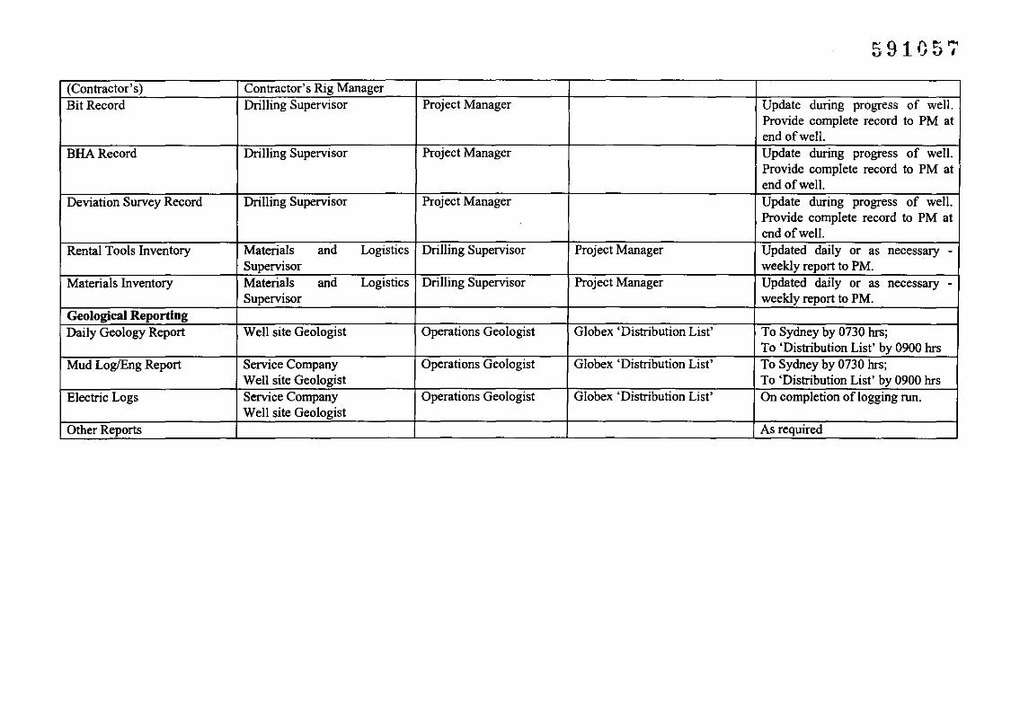
591057
(Contractor's) Contractor's Rig ManagerBit Record Drilling Supervisor Project Manager Update during progress of well.
Provide complete record to PM atend ofwell.
BHARecord Drilling Supervisor Project Manager Update during progress of well.Provide complete record to PM atend ofwell.
Deviation Survey Record Drilling Supervisor Project Manager Update during progress of well.Provide complete record to PM atend of well.
Rental Tools Inventory Materials and Logistics Drilling Supervisor Project Manager Updated daily or as necessary -Supervisor weekly report to PM.
Materials Inventory Materials and Logistics Drilling Supervisor Project Manager Updated daily or as necessary -Supervisor weekly report to PM.
Geological ReportingDaily Geology Report Well site Geologist Operations Geologist Globex 'Distribution List' To Sydney by 0730 hrs;
To 'Distribution List' by 0900 hrsMud Log/Eng Report Service Company Operations Geologist Globex 'Distribution List' To Sydney by 0730 hrs;
Well site Geologist To 'Distribution List' by 0900 hrsElectric Logs Service Company Operations Geologist Globex 'Distribution List' On completion oflogging run.
Well site GeologistOther Reports As required

APPENDIX B - TIME ANALYSIS
591058

591059
APPENDIX B - TIME ANALYSIS
For simplification, the order of time breakdown on the Daily Drilling Report has beenarranged in a similar way to the lADe Report. Additional categories more useful to Globexhave been included. The definitions for each element are provided as guidelines whencarrying out the time analysis in order to maintain consistency with different operations andfor comparison or bench marking purposes.
Code Element IADC Code Definition1 Move Rig All time from Rig release on last location to sub
structure spotted on next location - often on a lumpsum basis which includes Rig Up (2)
2 Rig Up 1 All time from sub base spotted on location untilRigged up and ready to make up the BHA.
3 Drilling 2 All time rotating on bottom 'making hole'4 Ream/Wash 3 All time from pick up kelly/top drive to commence
reaming or washing until trip can be recommencedor back on bottom drilling.
5 Coring 4 Includes time for trip to POH, make up core barrel,RIH, Core, POH, Lay down core barrel.
6 Circ.lCond 5 All time where the well is being circulated for thepurpose of i) conditioning the mud and hole ii) priorto POH for bit trip or to run logs, casing or corebarrel, iii) prior to LOT. Excludes time for circulatinggeological samples (see 27).
7 Trip 6 Trip for purpose of changing bit or bha. Where a topdrive is used, the time to pick up and lay backstands of drillpipe should be included.
8 Wiper Trip Trip for purpose of hole stability or conditioning whiledrilling.
9 Handle BHA Time to make up or lay down BHA. Note:IADC doesnot allow for this and time is allocated in trip time.
10 Rig Service 7 Normal Rig lube time - max half hour per tour.11 Rig Repair 8 All time where operations are suspended for Rig or
equipment failure. Includes trip/circulating time inecessary ie a trip to pull back to the shoe whilewaiting on Rig repairs should be logged as Repair.
12 Slip/Cut Line 9 Time to slip and cut drilling line.13 Survey 10 All time required for a directional survey including
cirCUlating prior to survey, runninglrecovery 0
survey barrel.14 Logging 11 Includes time to POH to log, Rig up, run logs, Rig
down (including wiper trip during logs).15 Case/Cement 12 Includes time for wiper trip after logging, Rig up, run
casing, cement, woe, time to drill out plugs, cement,shoe etc

591G60
16 Wellhead Time for installation of slips, wellhead, spools,run/test pack-off etc.
17 BOPS 14 Install and pressure test BOPs, divertors, manifolds,kill and choke lines, inside BOPs.
18 LOT Excludes time to circulate prior to LOT.19 Lost Circulation All time to cure lost circulation, including trip to lay
back bha if required (ie to RIH OEDP), spotting 0
Icm, gunk squeezes, cement and time to drillout.20 Kick Control All time from recognition of kick until normal
operations resumed.21 Sidetrack 20 Includes time to set kick-off plug if side-track for fish
is required - trips, circulating, cementing, dress plugetc. The trip to RIH to kick-off and subsequentoperations are classified under normal time breakdown with the well having a 'side-track' designation.
22 Fish/Stuck 19 All time lost due to stuck pipe or fishing (twist off etc)including circulating, spotting fluid, jarring, back-off,trips with fishing tools etc. to the point where a side-track plug is required (see 21)
23 Well Test 16 All time from commencement/Rig up testequipment/tools.
24 W/O Weather All time lost due to weather delays including trip outof hole (if necessary) to hang off.
25 Wait - Other Any other delay causing lost time - specify reason26 Abd.lSuspend 17 i) All time to abandon or suspend the well including
time required for trips to set cement plugs, cutcasing/wellheads, lay down drill pipe.ii) All time to abandon the lower part of a well for thepurpose of side-tracking to a new geologicalobjective.
27 Other ego time to circulate geological samples foevaluation.

591061
APPENDIX C PROVISIONAL LOAD OUT LIST

MATERIALS/EQUIPMENT LIST - GLOBEX - BARRAMUNDI-1591G62
Item Description Supplier Qty Serial/Pt No. Comments1 Services
1.01 Helicopter - Bell 412 Lloyd Based at Essendon1.02 AHSV - Pacific Shogun Swire Based in Geelong1.03 AHSV - Pacific Challenger Swire Based in Geelong1.04 Logistics/Materials Handling Toll Energy Based in Melbourne/Geelong1.05 Rig Positioning Racal1.06 Rig Positioning - Quality Control D.Evans1.07 Weather Forecasting WNI1.08 Cementina Equipment (Dowell Unit) Howco/DS Installed on ria1.09 ROV Sonsub Installed on rig1.10 Mud Logging Geoservices Installed on rig1.11 Electric Logging UnitITools Schlumberger Installed on rig1.12 Drilling Fluids Baroid1.13 Drilling Tools Tasman1.14 Casing Running Weatherford1.15 Coring BHI1.16 DST Testing Equipment Schlumberge1.17 Diesel Fuel Esso/Shell1.17 Communications Equipment1.18 Waste Disposal Hannon
2 Service personnel required on rig prior to spud2.01 Drilling Supervisors WW/LK 2 Prior to move for handover2.02 Wellsite Geologist GC 2 First flight ex Essendon2.03 Rig Positioning Crew Fugro 2 Esso flight pre-move2.04 Rig Positionina Quality Control Surveyor D.Evans 1 Esso flight pre-move2.05 Drilling Fluids Engineer Baroid 2 One should be on-board for tow2.06 Cementing Engineer Howco/DS 2 Remain on-board for tow2.07 Mud Logging Crew BHI 4 Remain on-board for tow2.08 ROVCrew Son sub 3 Remain on-board for tow2.09 Wellhead Engineer Dril-Quip 1 Esso flight pre-move2.10 Wireline Crew Schlumberge 3 TBA - no logging until TD

3 Drill 36"/26" hole, set 30" conductor 591063
Wellhead/Casmg/Casmg Runnmg/Cementmg
Item Description Supplier Qty SeriallPt No. Comments3.01 Drilling Fluids as per Baroid load out list Baroid3.02 Drill water
Rock Sits3.03 26" Rock Bit/nozzles - DSJC (Rental) Smith 1 PO A 98 005. Specify nozzles3.04 26" Bit Breaker Sedco 1
Drilling Too/s3.05 36" Hole opener - 7 5/8" Reg Conns Tasman 2 Specify jets required3.06 36" Stabiliser - 7 5/8" Reg Conns Tasman 13.07 9 1/2" Pony Drill Collar Tasman.
Wellhead Runnmg Too/s
3.08 30" Housing Type SS10 complete with Drilquip 1 Back-up in GeelongExt Joint - 1.5" wt, X52,HD90 Box
3.09 30" Cross-over Joint - HD90 pin x SF60 box Drilquip 1 Back-up in Geelong3.10 30" Intermediate Joint - SF60 pin x SF60 box Drilquip 1 Back-up in Geelong3.11 30" x 20" Shoe Joint - SF60 Pin Drilquip 1 Back-up in Geelong3.12 Permanent Guide base Drilquip 1 Back-up in Geelong3.13 Slope Indicator Drilquip 1 Back-up in Geelong3.14 20" Casing Drift Weatherford 1 To gauge extension joint3.15 Bestolife 2000 Thread Compound - 30lb Pails Weatherford 23.16 30" spillerlsllps<1.17 <lU' sloe ooor elevator Weatherford 23.18 Cement - Class G Halliburton 600 sx Approx - recalculate on site3.19 Calcium Chloride Baroid 1200lb3.20 De-Foamer - NF-3 Halliburton 2 gals.3.21 PGB Retrieval Tool Drilquip 2 346002-23.22 30" Wellhead Housing Running Tool Drilquip 2 420284-023.23 183/4" Housing Running Tool Drilquip 2 420002-023.24 183/4" BOP Test Tool Drilquip 2 420004-023.25 BOP Test Adaptor Drilquip 2 420005-023.26 18 3/4" Hanger/Seal Assembly RIT Drilquip 2 420028-023.27 183/4" Seal Assembly RIT Drilquip 2 420150-023.28 183/4" Multi-Purpose Tool Drilquip 2 452006-023.29 Bore Protector Running Adaptor Drilquip 2 452007-023.30 Wear Bushing Running Adapter Drilquip 2 452008-023.31 Bore Protector Retrieval Adaptor Drilquip 2 452010-02

3.32 Jet sub Drilquip 2 452056-023.33 Jet sub extension Drilquip 2 452033-023.34 Temp Abdonment Cap Running Tool Drilquip 1 330012-08 Keep in Geelong3.35 Emergency Drillpipe Hang Off Tool Drilquip 2 2-400256-023.36 Spares for running tools (as per DrilQuip list) Drilquip3.37 Spare '0' rings for connectors - 20" HD90 Drilquip 23.38 Spare '0' rinCls for connectors - 30" HD90 Drilquip 4
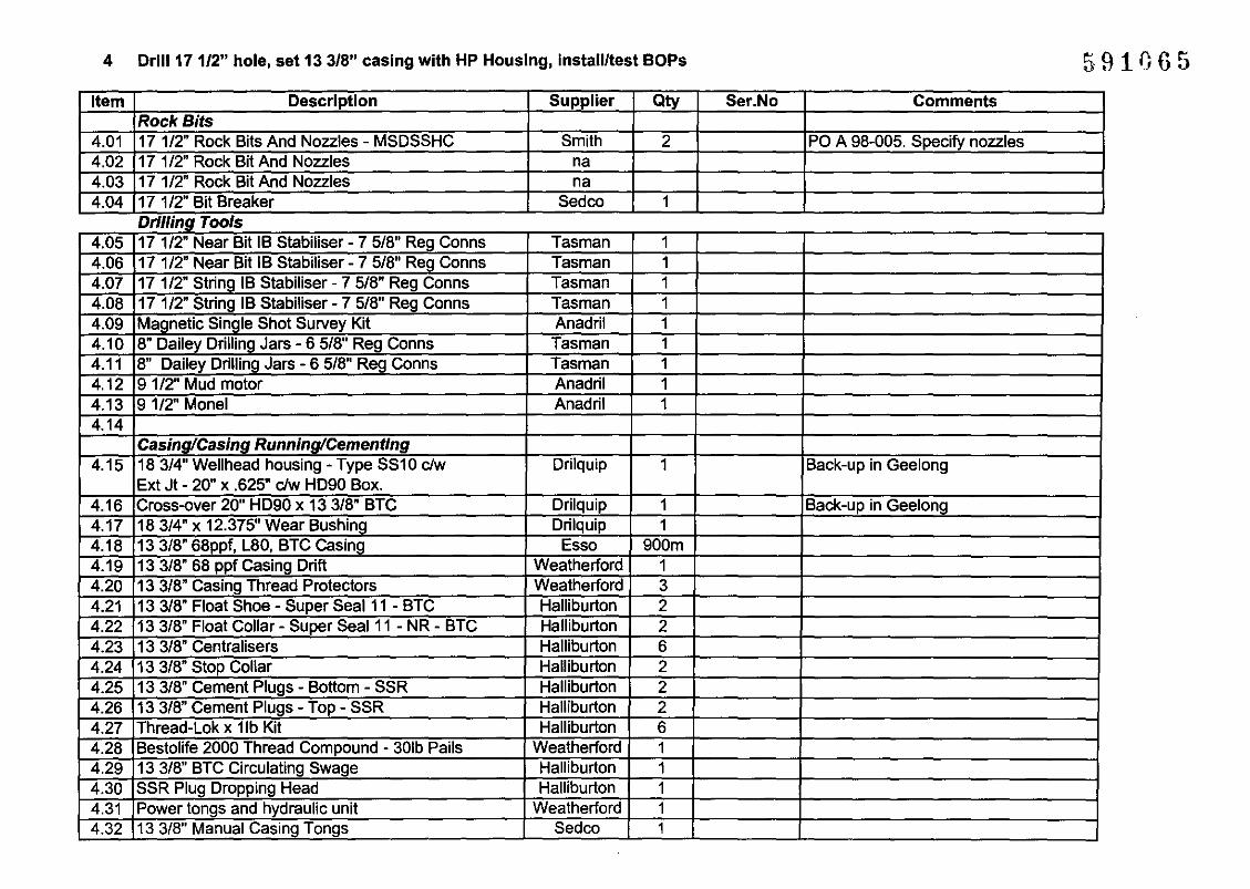
4 Drill 17 1/2" hole, set 13 3/8" casing with HP Housing, instaliitest BOPs 591065Item Description Supplier Qty Ser.No Comments
Rock Sits4.01 171/2" Rock Bits And Nozzles - MSDSSHC Smith 2 PO A 98-005. Specify nozzles4.02 17 1/2" Rock Bit And Nozzles na4.03 17 1/2" Rock Bit And Nozzles na4.04 17 1/2" Bit Breaker Sedco 1
Drlllmg Tools4.05 17 1/2" Near Bit IB Stabiliser - 7 5/8" Reg Conns Tasman 14.06 171/2" Near Bit IB Stabiliser - 75/8" Reg Conns Tasman 14.07 17 1/2" String IB Stabiliser - 7 5/8" Reg Conns Tasman 14.08 17 1/2" String IB Stabiliser - 7 5/8" Reg Conns Tasman 14.09 Magnetic Single Shot Survey Kit Anadril 14.10 8" Dailey Drilling Jars - 6 5/8" Reg Conns Tasman 14.11 8" Dailey Drilling Jars - 6 5/8" Reg Conns Tasman 14.12 9 1/2" Mud motor Anadril 14.13 91/2" Monel Anadril 14.14
Casing/Casing Running/Cementing4.15 183/4" Wellhead housing - Type SS10 clw Drilquip 1 Back-up in Geelong
Ext Jt - 20" x .625" cIw HD90 Box.4.16 Cross-over 20" HD90 x 13 3/8" BTC Drilquip 1 Back-up in Geelong4.17 183/4" x 12.375" Wear Bushing Drilquip 14.18 13 3/8" 68ppf, L80, BTC Casing Esso 900m4.19 13 3/8" 68 ppf Casing Drift Weatherford 14.20 13 3/8" Casing Thread Protectors Weatherford 34.21 13 3/8" Float Shoe - Super Seal 11 - BTC Halliburton 24.22 13 3/8" Float Collar - Super Seal 11 - NR - BTC Halliburton 24.23 13 3/8" Centralisers Halliburton 64.24 13 3/8" Stop Collar Halliburton 24.25 13 3/8" Cement Plugs - Bottom - SSR Halliburton 24.26 133/8" Cement Plugs - Top - SSR Halliburton 24.27 Thread-Lok x 11b Kit Halliburton 64.28 Bestolife 2000 Thread Compound - 30lb Pails Weatherford 14.29 13 3/8" BTC Circulating Swage Halliburton 14.30 SSR Plug Dropping Head Halliburton 14.31 Power tongs and hydraulic unit Weatherford 14.32 133/8" Manual Casing Tongs Sedco 1

IWeatherford 1L......;2:::./.::.3---l.1 ..lI.:::C:.::he:::c:.:k...::w:.:..:it:..:.h.:;:S.:::ed:::.;co:::::...:.if:...:n.:::e.:::ed:::.;e:::d=--- _AddItIonal ServIce Personnel for 171/2 8 Hole
4.40 ICasing running crew· if needed
4.33 13 3/8" Casing Slips CMS-XL Sedco 14.34 13 3/8" Side Door Elevator - 150 tonne Sedco 14.35 13 3/8" Single Joint Pick-up Elevator - 5 tonne Sedco 14.36 Slip Type Elevator and Spider - 500 tonne Sedco 1 each4.37 Cement - Class G Halliburton 1000 sx Approx - recalculate on site4.38 Cementing Chemicals Halliburton tba4.39 133/8" Cement RetainerlBridge Plugs Halliburton 1. . .

5 Drill 12 1/4" hole, set 9 5/S" (if required) 591067
litem 1,="':':"'C=~=_---,-D..:..es",c..:..r,,-iP-,-ti-,-o..:..n 1 Supplier I Qty , --' -'-C..:..om;....:....m..:e..:..n..:..ts'-- --J
Rock/PDC Bits
Casmg/Casmg Runnmg/Cementmg
5.01 121/4" Bits and Nozzles/Bit Breaker- PDC S91PX Smith 1 PO A 98-005 - specify nozzles5.02 121/4" Bits and Nozzles - 12 MD Smith 1 PO A 98-005 - ConsiQnment5.03 12 1/4" Bits and Nozzles5.04 121/4" Bits and Nozzles5.05 121/4" Bits and Nozzles5.06 12 1/4" Bit Breaker Sedco
Drilling Tools5.07 12 1/4" String IB Stabiliser - 6 5/8" Reg Conns Tasman 15.08 12 1/4" StrinQ IB Stabiliser - 6 5/8" Reg Conns Tasman 15.09 121/4" String IB Stabiliser - 6 5/8" Reg Conns Tasman 15.10 12 1/4" Near Bit IB Stabiliser - 6 5/8" Reg Conns Tasman 15.11 121/4" Near Bit IB Stabiliser - 6 5/8" Reg Conns Tasman 15.12 8" Shock Sub Tasman 15.13 8" Pony Drill Collar Tasman 15.14 8" Drilling Jars - 6 5/8" Reg Conns Tasman 25.15 8" Monel Drill Collar - 6 5/8" Reg Conns Tasman 2 Contingency5.16 9 1/2" Mud Motor Anadrill 25.17 Magnetic Single Shot Survey Equipment Anadrill 1
5.18 121/4" Flat Bottom Mill Tasman 15.19 12 1/4" Fishing Magnet Tasman 1
5.20 121/4" Reverse Circ Junk Basket Tasman 1
5.21 63/4" x 4" X 60' Core Barrel BHI 1
5.22 8 1/2" x 4" Core Heads BHI 35.23 63/4" x 4" Aluminium Inner Barrels x 9m BHI 15.24 Core Barrel Spares BHI 1
5.25 Core Saw BHI 15.26 Core Boxes BHI
5.27 Wellhead Recovery Tools Weatherford. .5.28 183/4" x 9 5/8" Casing Hanger - SS10C clw Dril-Quip 1 Back-up in Geelong
9 5/8" 47 ppf, L80, BTC Pup Joint (pin down)
5.29 Adaptor - Dummy hanger Dril-Quip 1 Back-up in Geelong5.30 18 3/4" Seal Assembly Dril-Quip 1 Back-up in Geelong5.31 183/4" x 9 5/8" Wear Bushing Dril-Quip 1

AddItIonal ServIce Personnel for 121/4 Hole
5.32 95/8", 47ppf, L80, LTC Casing Esso 1800m Retain in Sale until needed5.33 95/8", 47ppf, L80, XlO, BTC Box x LTC Pin Baker 2 Retain in Sale until needed5.34 9 5/8" 47 ppf Casino Drift Weatherford 15.35 9 5/8" Casing Thread Protectors Weatherford 35.36 9 5/8" LTC Float Shoe Halliburton 25.37 9 5/8" LTC Float Collar Halliburton 25.38 9 5/8" Centralisers Halliburton 105.39 9 5/8" Stop Rings Halliburton 105.40 9 5/8" Cement Plugs - SSR Halliburton 25.41 9 5/8" Circulating Swage - LTC Halliburton 25.42 SSR Plug Dropping Head Halliburton 15.43 9 5/8" Safety Clamp Sedco 15.44 9 5/8" Side Door Elevator Sedco 15.45 9 5/8" Single Joint Pick-up Elevator Sedco 15.46 Slip Type Elevator/Spider Dressed for 9 5/8" Sedco 15.47 Power tongs and hydraulic unit Weatherford 15.48 Cement - Class G Halliburton tba5.49 Cementing Chemicals Halliburton tba As per cement test5.50 9 5/8" Cement Retainer/Bridge Plugs Halliburton 15.51 Mech Setting Tool Halliburton 15.52 95/8" RTTS Halliburton 1.. . ..
L..::.5:.:::.5~3-,I..:;C.::;as:;;in",g,-,ru..:;;..::nn..:;;in",g<-c:.:.re.;;..w,,-- 1 Weatherford I 2/3 1 _

APPENDIX D - CASING DIAGRAMS
5911}6~

591G70
GLOBEX FAR EAST
Barramundi-1 - 30" Wellhead/Casing
I I
30" Housing + Ext. Joint - 30" x 1.S" wt, XS2, R111
I I HD-90 Box
HD-90 Pin
Cross-over Joint - 30" x 1" wt, XS2, R111
SF-50 Box
SF-50 Pin
Intermediate Joint - 30" x 1" wt, XS2, R111
I I SF-50 Box
I I SF-50 Pin
30" Extension x 1.8m
Shoe Joint
20" Extension x 7.6m
20" Davies Lynch Float Shoe-,. Scm ..,
:DQ-WHD.xlsigr/19-5-99

591071
I GLOBEX FAR EAST II Barramundi·1 -183/4" Wellhead/Casing I
I I
183/4" Housing+ Ext. Joint· 20" x 0.625" wt, X56 x 5.8m Ig
HD-90 Box
I I HD-90 Pin
Cross-over Swedge • 20" x 13 3/S" x 4.5m approxWP =3000psi
13 3/8" 68ppf. L80 BTC Pin
9 5/S" Casing Hanger
9 5/8" Pup Joint - 47ppf, L80, BTC x 3m approx
I. 5cm )III
:DQ-WHD.xls/gr/19-5-99

CASING SHOE TRACKS - BARRAMUNDI-l
Casing collar - back-out, apply thread locking compound, make-up
FLOAT COLLAR JOINT
Halliburton Float Collar - thread lock
Casing collar - back-out, apply thread locking compound, make-up
INTERMEDIATE JOINT - I
Casing collar - back-out, apply thread locking compound, make-up
FLOAT SHOE JOINT
Halliburton Float Shoe - thread lock
591072
Requirement - I complete shoe tracks each size:
13 3/8", 68 ppf, K55, BTC Casing
95/8",47 ppf, K55, LTC Casing
f:shoe.tk.doc
Scm