
Gi bit P i O ti l N t k (GPON)Gigabit Passive Optical ... · PDF fileGi bit P i O ti l N t k...
37
Gi bit P i O ti lN t k (GPON) Gigabit P assive Optical Networks (GPON): Making Waves in Your Local Area Network John Hoover Tellabs, Inc. Senior Product Manager [email protected]
-
Upload
nguyenminh -
Category
Documents
-
view
219 -
download
0
Transcript of Gi bit P i O ti l N t k (GPON)Gigabit Passive Optical ... · PDF fileGi bit P i O ti l N t k...
Gi bit P i O ti l N t k (GPON)Gigabit Passive Optical Networks (GPON): Making Waves in Your Local Area Network
John HooverTellabs, Inc.
Senior Product [email protected]

Presentation Outline1 - Introduction to GPON Technology
• Fundamentals of GPON Architecture• Benefits of Optical LANsBenefits of Optical LANs
2 - Designs Considerations for a GPON Network• Comparison to Active Ethernet and Traditional Copper/Fiber Deployment• Analog voice and VoIP support• RF video and IP video support• Sample Floor Plan• Extending GPON Architecture to your Campus/Base• Secured PON Solution• PON redundancy
3 - Structured Cabling Review• Fiber Technologies Overview• Remote ONT Powering• Remote ONT Powering• Testing for GPON Infrastructure
4 - Standards Bodies Considerations• Current Standards Limitations Impacting GPON Design• Recent Standards Updates to Support GPON based Infrastructure• Suggestions for Modification to the Standards Bodies
5 - Q&A2
Section 1
Introduction to GPON Technology
3
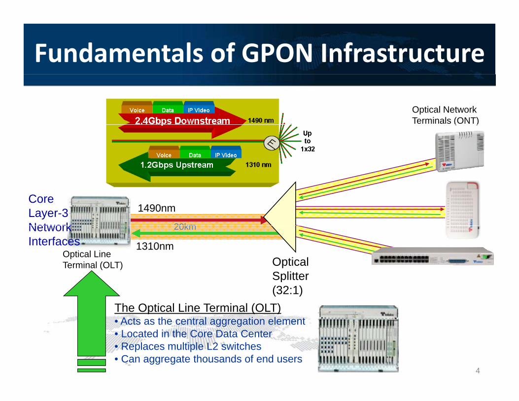
Fundamentals of GPON Infrastructure
Optical Network Terminals (ONT)( )
1490nmCore Layer-3 Network 20km
OpticalSplitter
Optical Line Terminal (OLT)
1310nm
Network Interfaces
20km
Splitter(32:1)
The Optical Line Terminal (OLT)• Acts as the central aggregation element• Located in the Core Data Center• Replaces multiple L2 switches• Can aggregate thousands of end users
4

Fundamentals of GPON Infrastructure
Optical Network Terminals (ONT)( )
1490nmCore Layer-3 Network 20km
OpticalSplitter
Optical Line Terminal (OLT)
1310nm
Network Interfaces
20km
Passive Optical Network (PON)• Completely passive infrastructure• Single fiber carries multiple wavelengths
Splitter(32:1)
Single fiber carries multiple wavelengths• 2.48 Gbps downstream• 1.24 Gbps upstream•Serve Remote Bldgs Up to 20Km
5
Fundamentals of GPON Infrastructure
Optical Network Terminals (ONT)( )
1490nmCore Layer-3 Network 20km
P i O ti l S litt F di FDHOpticalSplitter
Optical Line Terminal (OLT)
1310nm
Network Interfaces
20km
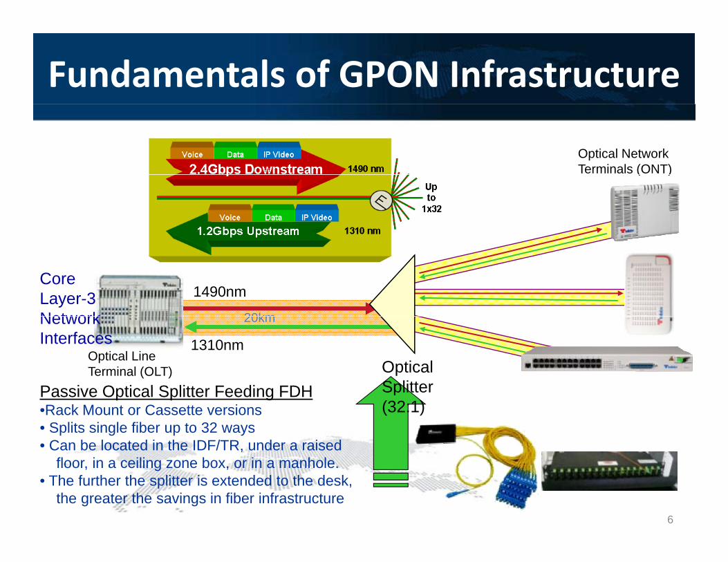
Passive Optical Splitter Feeding FDH•Rack Mount or Cassette versions• Splits single fiber up to 32 ways• Can be located in the IDF/TR, under a raised
fl i ili b i h l
Splitter(32:1)
floor, in a ceiling zone box, or in a manhole.• The further the splitter is extended to the desk,
the greater the savings in fiber infrastructure6
Fundamentals of GPON Infrastructure
Optical Network Terminals (ONT)( )
1490nmCore Layer-3 Network 20km
OpticalSplitter
Optical Line Terminal (OLT)
1310nm
Network Interfaces
20km
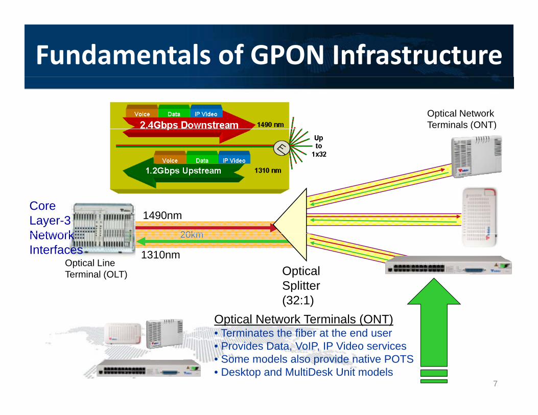
Optical Network Terminals (ONT)• Terminates the fiber at the end user
Splitter(32:1)
• Provides Data, VoIP, IP Video services• Some models also provide native POTS• Desktop and MultiDesk Unit models
7
Fundamentals of GPON Infrastructure
Optical Network Terminals (ONT)( )
1490nmCore Layer-3 Network 20km
OpticalSplitter
Optical Line Terminal (OLT)
1310nm
Network Interfaces
20km
Splitter(32:1)
8
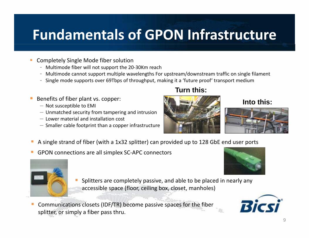
Fundamentals of GPON Infrastructure Completely Single Mode fiber solution
- Multimode fiber will not support the 20-30Km reach- Multimode cannot support multiple wavelengths For upstream/downstream traffic on single filament- Multimode cannot support multiple wavelengths For upstream/downstream traffic on single filament- Single mode supports over 69Tbps of throughput, making it a ‘future proof‘ transport medium
Benefits of fiber plant vs. copper:N ibl EMI
Turn this:Into this:– Not susceptible to EMI
– Unmatched security from tampering and intrusion– Lower material and installation cost– Smaller cable footprint than a copper infrastructure
Into this:
GPON connections are all simplex SC-APC connectors
A single strand of fiber (with a 1x32 splitter) can provided up to 128 GbE end user ports
Splitters are completely passive, and able to be placed in nearly any accessible space (floor, ceiling box, closet, manholes)
Communications closets (IDF/TR) become passive spaces for the fiber splitter, or simply a fiber pass thru.
9
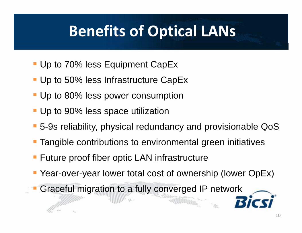
Benefits of Optical LANs
Up to 70% less Equipment CapEx
Up to 50% less Infrastructure CapEx
Up to 80% less power consumption
Up to 90% less space utilization
5-9s reliability, physical redundancy and provisionable QoSy p y y p
Tangible contributions to environmental green initiatives
Future proof fiber optic LAN infrastructureFuture proof fiber optic LAN infrastructure
Year-over-year lower total cost of ownership (lower OpEx)
Graceful migration to a fully converged IP network
10
Graceful migration to a fully converged IP network

Fiber based PON deployments
11Source: TE Connectivity Optical LAN Systems Capabilities Overview and Fast Facts
Section 2
Design Considerations for a GPON Network
12
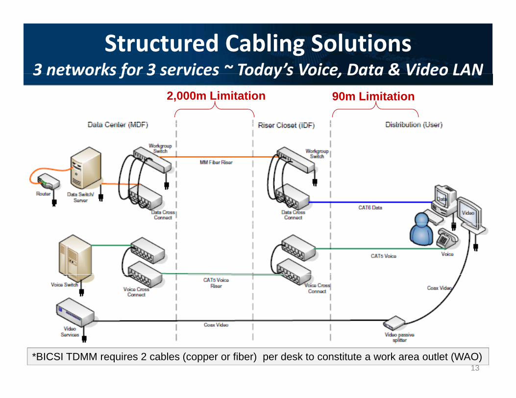
Structured Cabling Solutions3 networks for 3 services ~ Today’s Voice, Data & Video LAN3 networks for 3 services Today s Voice, Data & Video LAN
90m Limitation2,000m Limitation
13*BICSI TDMM requires 2 cables (copper or fiber) per desk to constitute a work area outlet (WAO)13
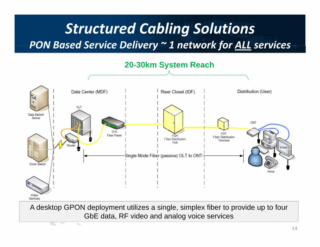
Structured Cabling SolutionsPON Based Service Delivery ~ 1 network for ALL services
20-30km System Reach
PON Based Service Delivery 1 network for ALL services
A desktop GPON deployment utilizes a single, simplex fiber to provide up to four GbE data, RF video and analog voice services
14
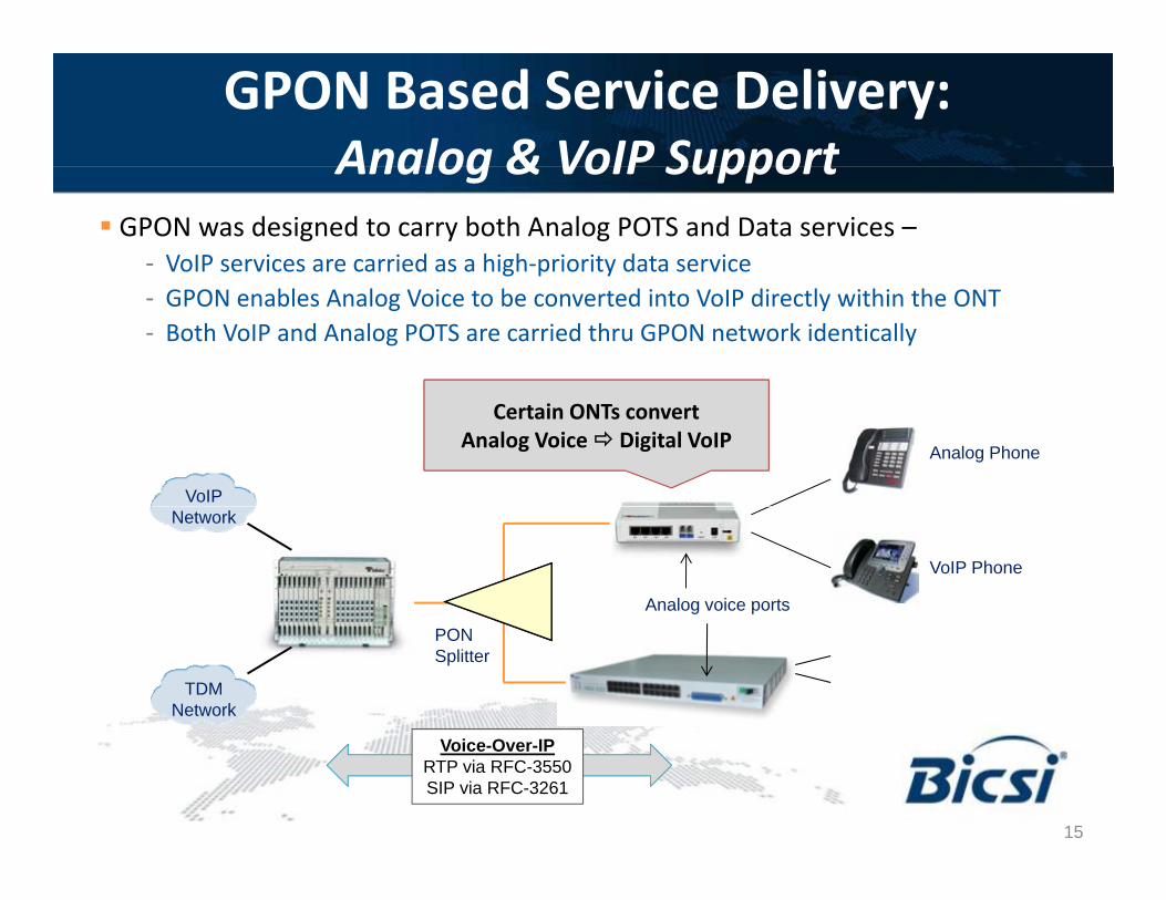
GPON Based Service Delivery:Analog & VoIP SupportAnalog & VoIP Support
GPON was designed to carry both Analog POTS and Data services –- VoIP services are carried as a high-priority data service- GPON enables Analog Voice to be converted into VoIP directly within the ONT- Both VoIP and Analog POTS are carried thru GPON network identically
Analog Phone
Certain ONTs convertAnalog Voice Digital VoIP
VoIP
VoIP Phone
Analog voice ports
Network
PONSplitter
TDMNetwork
15
Voice-Over-IPRTP via RFC-3550SIP via RFC-3261
15
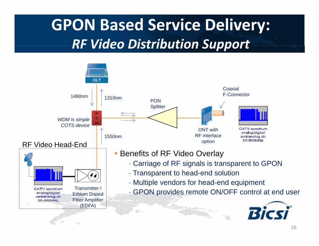
GPON Based Service Delivery:RF Video Distribution SupportRF Video Distribution Support
PONSplitter
OLT
1310nm1490nmCoaxialF-Connector
SplitterWDM
1550nmONT with
RF interface
WDM is simpleCOTS device
RF Video Head-End option
Benefits of RF Video Overlay - Carriage of RF signals is transparent to GPON
Transmitter /Erbium DopedFiber Amplifier
- Transparent to head-end solution- Multiple vendors for head-end equipment- GPON provides remote ON/OFF control at end user
Fiber Amplifier(EDFA)
16
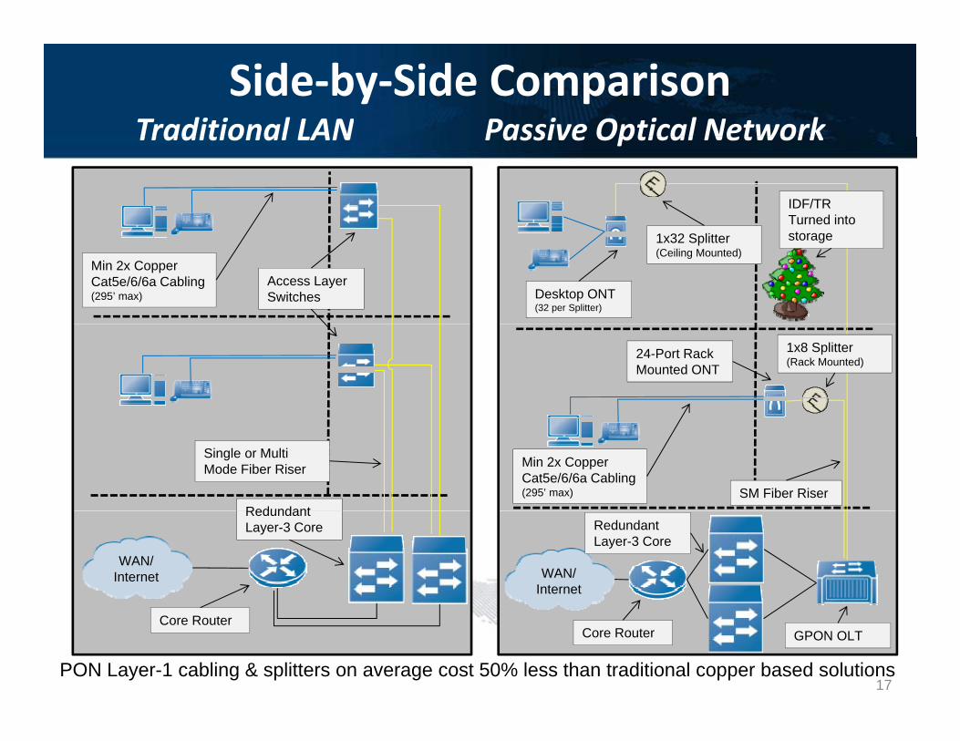
Side-by-Side ComparisonTraditional LAN Passive Optical NetworkTraditional LAN Passive Optical Network
IDF/TR Turned into
Access Layer Switches
Min 2x Copper Cat5e/6/6a Cabling (295’ max)
1x32 Splitter(Ceiling Mounted)
Desktop ONT(32 per Splitter)
storage
1x8 Splitter(Rack Mounted)
24-Port Rack Mounted ONT
Redundant
Single or Multi Mode Fiber Riser
SM Fiber Riser
Min 2x Copper Cat5e/6/6a Cabling (295’ max)
WAN/Internet
Redundant Layer-3 Core
WAN/Internet
Redundant Layer-3 Core
PON Layer-1 cabling & splitters on average cost 50% less than traditional copper based solutions
Core RouterCore Router GPON OLT
17

Sample Floor Plan Layoutp y Each zone is broken into
between 19 and 24 ONTs, allowing for a 25% sparing of
OLT Rack & Core NetworkSimplex SM OFNP (rec 2
strands for growth)
g p gsplitter ports for growth
J-Hook pathways are more than adequate to support the small amount of single mode g )
Desk Mounted ONT (Single SM Fiber from
small amount of single mode fiber.
ONTs can be plugged in at the desk or powered with
(Single SM Fiber from Zone Box mounted splitterphantom network power (2
conductor for DC power under the same jacket as the fiber), and fed from the ceiling zone box with a 1RU
Ceiling Mounted Zone Box (contains 1RU Splitter)
ceiling zone box with a 1RU power distribution unit
ONT can be enclosed, allowing the ports to be
t d d f th ONT textended from the ONT to modular furniture outlet plates
18
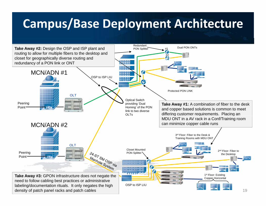
Campus/Base Deployment ArchitectureRedundant PON Splitter #1
#2
Dual PON ONTsTake Away #2: Design the OSP and ISP plant and routing to allow for multiple fibers to the desktop and closet for geographically diverse routing and redundancy of a PON link or ONT
MCN/ADN #1OSP to ISP LIU
P t t d PON LINK
redundancy of a PON link or ONT
PeeringPoint
OLTOptical Switch providing ‘Dual Homing’ of the PON link to two diverse OLTs
Protected PON LINK
Take Away #1: A combination of fiber to the desk and copper based solutions is common to meet differing customer requirements. Placing an
MCN/ADN #23rd Floor: Fiber to the Desk & Training Rooms with MDU ONT
g q gMDU ONT in a AV rack in a Conf/Training room can minimize copper cable runs
PeeringPoint
OLTCloset MountedPON Splitter
2nd Floor: Fiber tothe Desktop
OSP to ISP LIU
1st Floor: ExistingCopper Horizontal
Take Away #3: GPON infrastructure does not negate the need to follow cabling best practices or administrative labeling/documentation rituals. It only negates the high density of patch panel racks and patch cables 19
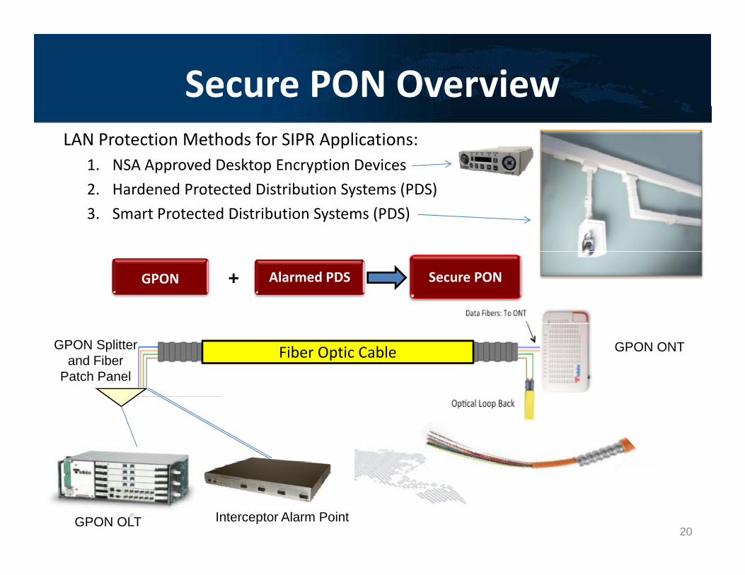
Secure PON OverviewLAN Protection Methods for SIPR Applications:
1. NSA Approved Desktop Encryption Devices2. Hardened Protected Distribution Systems (PDS)3. Smart Protected Distribution Systems (PDS)
GPON Alarmed PDS Secure PON+
Fiber Optic CableGPON Splitter and Fiber
Patch Panel
GPON ONT
GPON OLT Interceptor Alarm Point20
PON Redundancy Optionsy p GPON Optical LAN solution provides for 99.999% availability
i h i l PON i f h ONTwith a single PON interface to the ONTs
This deployment architecture meets the UCR 2008 i t f N C2 d C2requirements for Non-C2 and C2 users
- Maximum 96 VoIP phones on a single unprotected link
Certain network deployments require a redundant fiber path Certain network deployments require a redundant fiber path (facility) to the communication closet- Example: Special C2 users
For these deployment needs, Optical LAN solutions offer the following PON redundancy options…
21
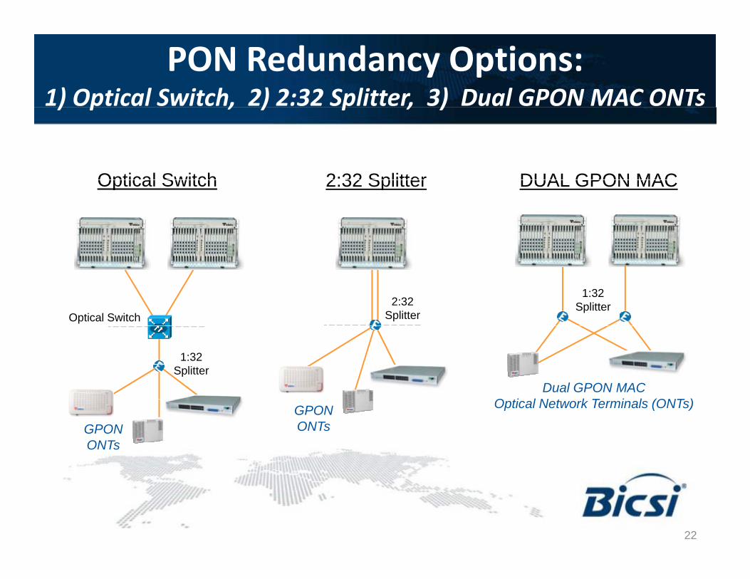
PON Redundancy Options:1) Optical Switch, 2) 2:32 Splitter, 3) Dual GPON MAC ONTs) p , ) p , )
Optical Switch 2:32 Splitter DUAL GPON MACOptical Switch 2:32 Splitter DUAL GPON MAC
2:32Splitter
1:32Splitter
Optical Switch
1:32Splitter
Dual GPON MACO ti l N t k T i l (ONT )
GPONONTs
GPONONTs
Optical Network Terminals (ONTs)
22
Section 3Section 3
Structured Cabling OverviewStructured Cabling Overview
23
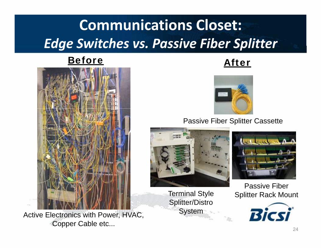
Communications Closet:Edge Switches vs Passive Fiber SplitterEdge Switches vs. Passive Fiber Splitter
Before After
Passive Fiber Splitter Cassette
Passive Fiber Splitter Rack MountTerminal Style
Splitter/Distro
Active Electronics with Power, HVAC, Copper Cable etc...
Splitter/Distro System
24
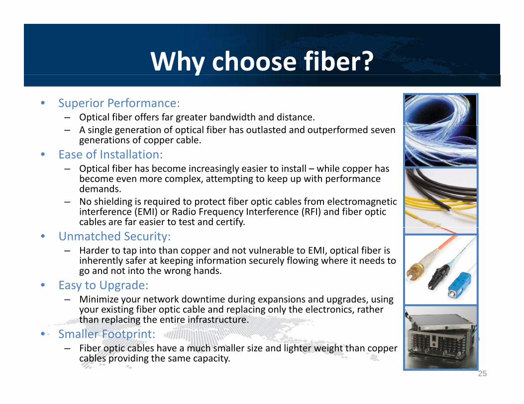
Why choose fiber?y• Superior Performance:
– Optical fiber offers far greater bandwidth and distance.– A single generation of optical fiber has outlasted and outperformed seven
generations of copper cable.• Ease of Installation:
– Optical fiber has become increasingly easier to install – while copper has b l tt ti t k ith fbecome even more complex, attempting to keep up with performance demands.
– No shielding is required to protect fiber optic cables from electromagnetic interference (EMI) or Radio Frequency Interference (RFI) and fiber optic cables are far easier to test and certify.
• Unmatched Security:– Harder to tap into than copper and not vulnerable to EMI, optical fiber is
inherently safer at keeping information securely flowing where it needs to go and not into the wrong hands.
• Easy to Upgrade:– Minimize your network downtime during expansions and upgrades, using
your existing fiber optic cable and replacing only the electronics, rather than replacing the entire infrastructure.ll i• Smaller Footprint:
– Fiber optic cables have a much smaller size and lighter weight than copper cables providing the same capacity.
25
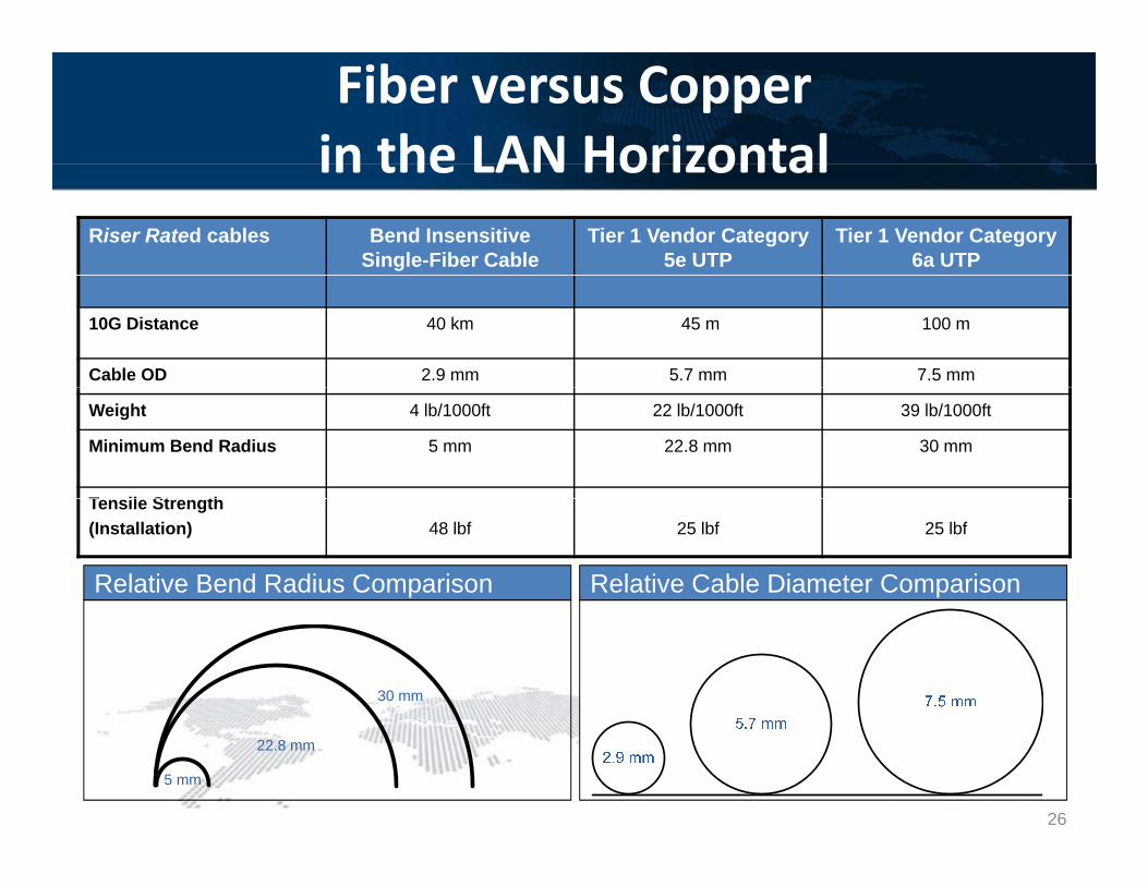
Fiber versus Copper in the LAN Horizontalin the LAN Horizontal
Riser Rated cables Bend Insensitive Single-Fiber Cable
Tier 1 Vendor Category 5e UTP
Tier 1 Vendor Category 6a UTP
10G Distance 40 km 45 m 100 m
Cable OD 2.9 mm 5.7 mm 7.5 mm
Weight 4 lb/1000ft 22 lb/1000ft 39 lb/1000ft
Minimum Bend Radius 5 mm 22.8 mm 30 mm
T il St th
Relative Bend Radius Comparison
Tensile Strength(Installation) 48 lbf 25 lbf 25 lbf
Relative Cable Diameter Comparison
30 mm
5 mm
22.8 mm
26
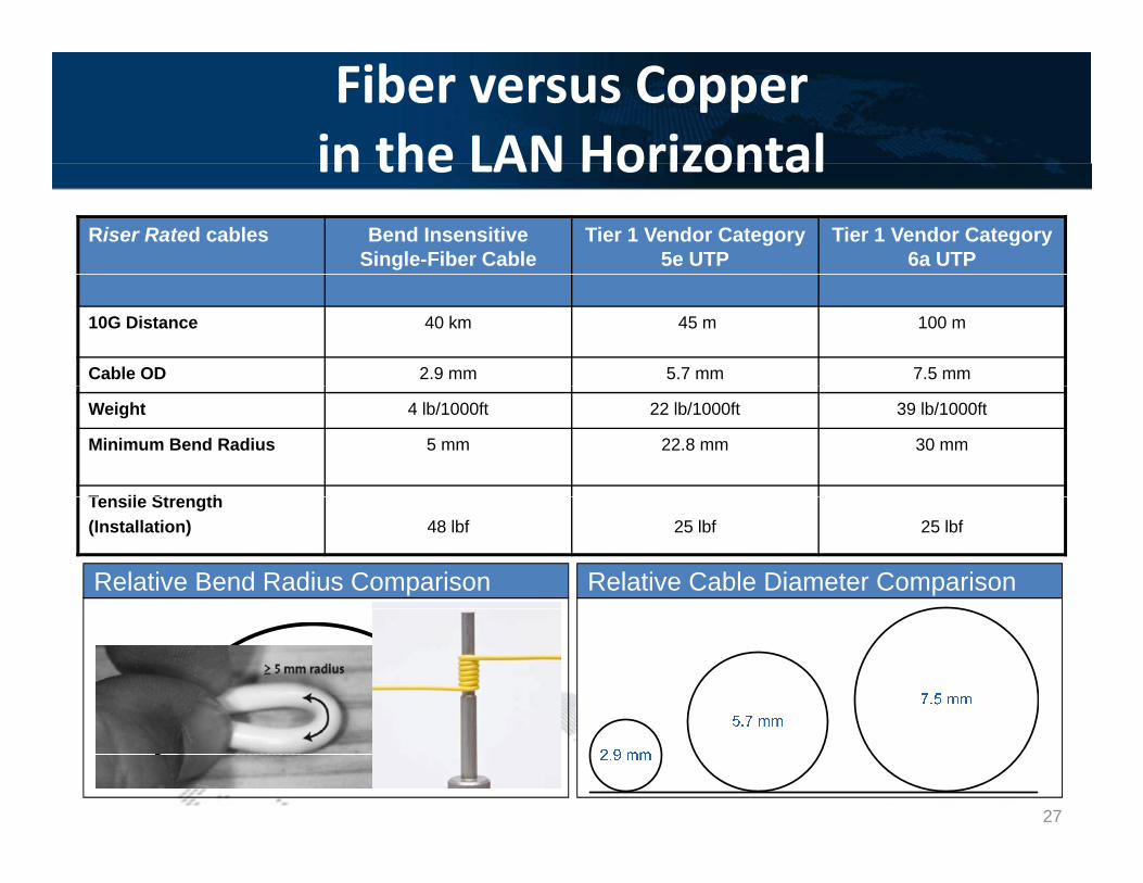
Fiber versus Copper in the LAN Horizontalin the LAN Horizontal
Riser Rated cables Bend Insensitive Single-Fiber Cable
Tier 1 Vendor Category 5e UTP
Tier 1 Vendor Category 6a UTP
10G Distance 40 km 45 m 100 m
Cable OD 2.9 mm 5.7 mm 7.5 mm
Weight 4 lb/1000ft 22 lb/1000ft 39 lb/1000ft
Minimum Bend Radius 5 mm 22.8 mm 30 mm
T il St th
Relative Bend Radius Comparison
Tensile Strength(Installation) 48 lbf 25 lbf 25 lbf
Relative Cable Diameter Comparison
30 mm
5 mm
22.8 mm
27

Optical LAN Remote Powering ONTsHybrid Fiber / CopperHybrid Fiber / Copper
Communication ClosetWalls and Ceiling –Structured Cabling Office Environment
Solution provided in conjunction with
infrastructure partnerOpt. FDT
10/2 Low Voltage Cable
Single Mode Link & 22/2 Low Voltage Power Cable
Under a Single Jacket
2x2 Ceiling Zone Box w/ 1x32 1RU Splitter and 1RU
Bulk rectifier with battery back-up, can be existing system.
Provides 48Vdc to existing Cat5 cables or hybrid fiber/copper cable
Rectifier
1x32 1RU Splitter and 1RU power distribution unit (32x
1.5A -48Vdc outputs)
Cable Gauge Max Distance22/2 250
Main Aggregation Room
FDH
• • • 709GP ONTw/ 48Vdc input
22/2 25020/2 35018/2 50016/2 75014/2 1000
Main Aggregation Room
Benefits include: 1) Eliminates any requirement for local AC or DC power at the
desk. Ideal or placing PoE ONTs in the ceiling plenum without an AC connection
2) Centralizes battery and potentially increases battery back up time at the TR/IDF ClosetTellabs 1150 OLT
28
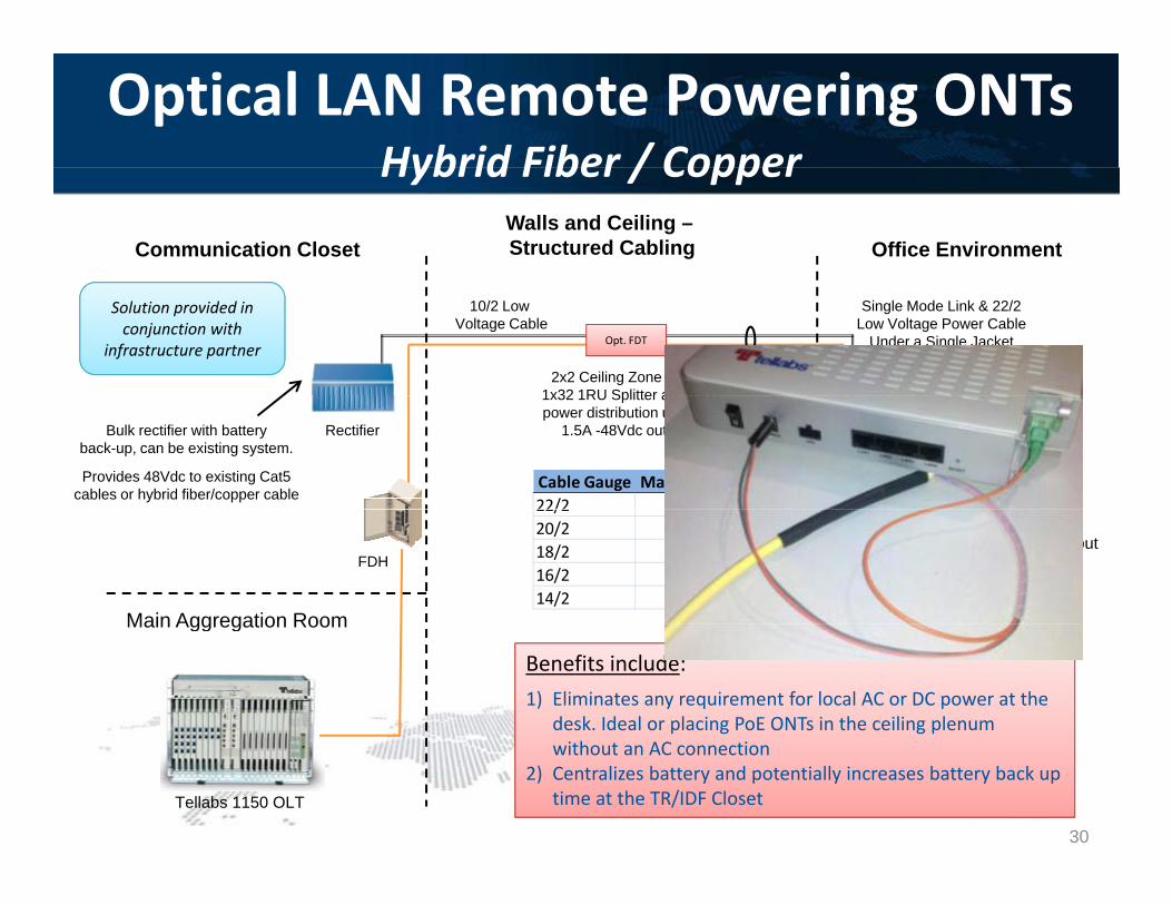
Optical LAN Remote Powering ONTsHybrid Fiber / CopperHybrid Fiber / Copper
Communication ClosetWalls and Ceiling –Structured Cabling Office Environment
Solution provided in conjunction with
infrastructure partnerOpt. FDT
10/2 Low Voltage Cable
Single Mode Link & 22/2 Low Voltage Power Cable
Under a Single Jacket
2x2 Ceiling Zone Box w/ 1x32 1RU Splitter and 1RU
Bulk rectifier with battery back-up, can be existing system.
Provides 48Vdc to existing Cat5 cables or hybrid fiber/copper cable
Rectifier
1x32 1RU Splitter and 1RU power distribution unit (32x
1.5A -48Vdc outputs)
Cable Gauge Max Distance22/2 250
Main Aggregation Room
FDH
• • • 709GP ONTw/ 48Vdc input
22/2 25020/2 35018/2 50016/2 75014/2 1000
Main Aggregation Room
Benefits include: 1) Eliminates any requirement for local AC or DC power at the
desk. Ideal or placing PoE ONTs in the ceiling plenum without an AC connection
2) Centralizes battery and potentially increases battery back up time at the TR/IDF ClosetTellabs 1150 OLT
29
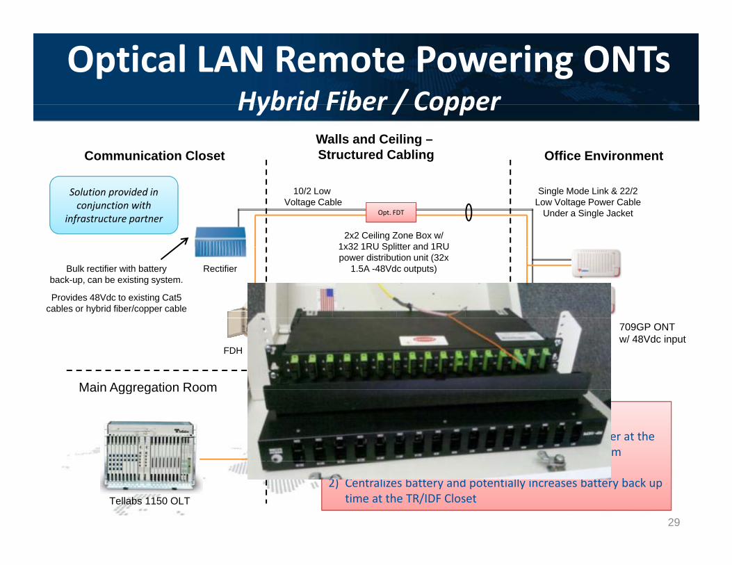
Optical LAN Remote Powering ONTsHybrid Fiber / CopperHybrid Fiber / Copper
Communication ClosetWalls and Ceiling –Structured Cabling Office Environment
Solution provided in conjunction with
infrastructure partnerOpt. FDT
10/2 Low Voltage Cable
Single Mode Link & 22/2 Low Voltage Power Cable
Under a Single Jacket
2x2 Ceiling Zone Box w/ 1x32 1RU Splitter and 1RU
Bulk rectifier with battery back-up, can be existing system.
Provides 48Vdc to existing Cat5 cables or hybrid fiber/copper cable
Rectifier
1x32 1RU Splitter and 1RU power distribution unit (32x
1.5A -48Vdc outputs)
Cable Gauge Max Distance22/2 250
Main Aggregation Room
FDH
• • • 709GP ONTw/ 48Vdc input
22/2 25020/2 35018/2 50016/2 75014/2 1000
Main Aggregation Room
Benefits include: 1) Eliminates any requirement for local AC or DC power at the
desk. Ideal or placing PoE ONTs in the ceiling plenum without an AC connection
2) Centralizes battery and potentially increases battery back up time at the TR/IDF ClosetTellabs 1150 OLT
30
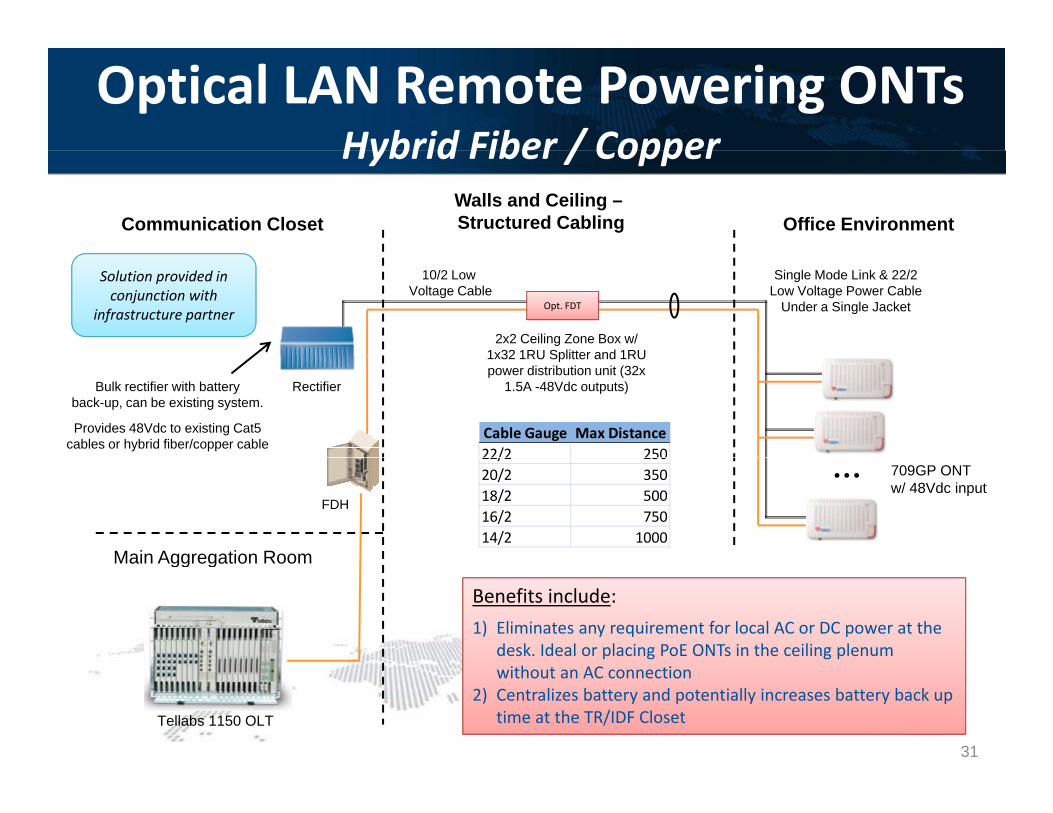
Optical LAN Remote Powering ONTsHybrid Fiber / CopperHybrid Fiber / Copper
Communication ClosetWalls and Ceiling –Structured Cabling Office Environment
Solution provided in conjunction with
infrastructure partnerOpt. FDT
10/2 Low Voltage Cable
Single Mode Link & 22/2 Low Voltage Power Cable
Under a Single Jacket
2x2 Ceiling Zone Box w/ 1x32 1RU Splitter and 1RU
Bulk rectifier with battery back-up, can be existing system.
Provides 48Vdc to existing Cat5 cables or hybrid fiber/copper cable
Rectifier
1x32 1RU Splitter and 1RU power distribution unit (32x
1.5A -48Vdc outputs)
Cable Gauge Max Distance22/2 250
Main Aggregation Room
FDH
• • • 709GP ONTw/ 48Vdc input
22/2 25020/2 35018/2 50016/2 75014/2 1000
Main Aggregation Room
Benefits include: 1) Eliminates any requirement for local AC or DC power at the
desk. Ideal or placing PoE ONTs in the ceiling plenum without an AC connection
2) Centralizes battery and potentially increases battery back up time at the TR/IDF ClosetTellabs 1150 OLT
31

Testing Simplex SM Fiber for GPONg p A standard power loss test at 1490nm (GPON Downstream) and 1550nm (RF video) is sufficient for
certifying an in building GPON fiber network New OSP cabling should be subject to OTDR testing in addition to a channel link power loss testNew OSP cabling should be subject to OTDR testing in addition to a channel link power loss test. The channel link should be tested from the fiber connecting to the OLT PON port, thru the splitter, to
the fiber connecting to the ONT The total loss permitted in a GPON network (per the ITU standards) is 8 to 28 dB including the splitter,
fiber loss over distance and combined splices (max 75dB/connector) and adapter panelsfiber loss over distance, and combined splices (max .75dB/connector) and adapter panels
OLT Splitter(1x32: ~16.7 dB loss)
GPON ONT
Channel Link(8 – 28 dB Loss Budget)
Item Qty Loss (dB) Total Loss (dB)Total Channel Link Distance (km): 4 0.5 2Total Fusion Splices 4 0.1 0.4
Sample GPON Channel Link Test
Total Mechanical Connectors 4 0.4 1.6Total Bulkhead Adapters 3 0.7 2.1Passive 1x32 Splitter 1 16.7 16.7
Total Channel Link Loss: 22.8 32
Section 4Section 4
Standards Bodies Limitations and SuggestionsStandards Bodies Limitations and Suggestions
33
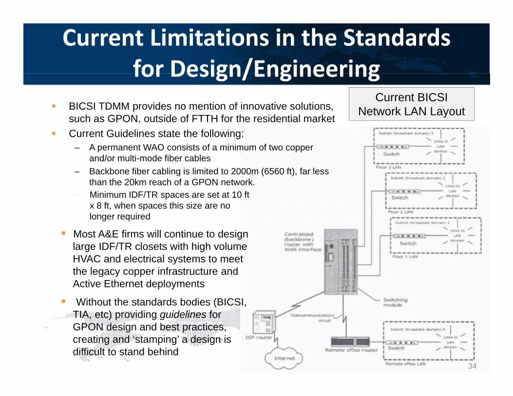
Current Limitations in the Standards for Design/Engineeringfor Design/Engineering
BICSI TDMM provides no mention of innovative solutions, such as GPON, outside of FTTH for the residential market
Current BICSI Network LAN Layout,
Current Guidelines state the following:– A permanent WAO consists of a minimum of two copper
and/or multi-mode fiber cables– Backbone fiber cabling is limited to 2000m (6560 ft) far lessBackbone fiber cabling is limited to 2000m (6560 ft), far less
than the 20km reach of a GPON network.– Minimum IDF/TR spaces are set at 10 ft
x 8 ft, when spaces this size are no longer required
Most A&E firms will continue to design large IDF/TR closets with high volume HVAC and electrical systems to meet the legacy copper infrastructure andthe legacy copper infrastructure and Active Ethernet deployments
Without the standards bodies (BICSI, TIA, etc) providing guidelines for GPON d i d b iGPON design and best practices, creating and ‘stamping’ a design is difficult to stand behind
34
Recent Standards BodyInclusion of GPONInclusion of GPON
The current TIA/EIA 568 C draft standard provides inclusion for GPON The current TIA/EIA-568-C draft standard provides inclusion for GPON distances and the high dB loss budget of a GPON network. This standard will allow A&E firms and engineers to reference a valid standards number in their GPON specifications. (due to be voted on in Dec-2011)
Department of Defense has made many recent inclusions of GPON technology in recent solicitations, allowing for industry comment and suggestions to the
li it ti i t lsolicitation requirements language.
The most recent version of the Unified Capabilities Requirements (UCR 2008 Change 3) has specific sections devoted to GPON networks in the military.
35

Section 5Section 5
Q&A
36