GFT GROUND FIXED TILT INSTALLATION GUIDE - Unirac
38
INSTALLATION GUIDE NOTE: GFT construction drawings have precedence over these installation guidelines. GFT GROUND FIXED TILT TABLE OF CONTENTS A - PRIMARY COMPONENTS B - OVERALL VIEW OF COMPONENTS C - END AND MID CLAMPS ASSEMBLIES D - BEAM CLIP AND BEAM SPLICE E - TOP CHORD AND DIAGONAL BRACE PILE CONNECTIONS 1-22 - STEP BY STEP INSTALLATION INSTRUCTIONS 23 - ELECTRICAL CONSIDERATIONS 24 - BONDING GROUND PATHS 25 - MODULE COMPATABILITY 27 - APPENDIX TABLE OF CONTENTS PUB2021JAN18
Transcript of GFT GROUND FIXED TILT INSTALLATION GUIDE - Unirac
INSTALLATION GUIDE
PUB18APR16
NOTE: GFT construction
drawings have precedence over these installation guidelines.
GFT GROUNDFIXEDTILT
TABLE OF CONTENTSA - PRIMARY COMPONENTSB - OVERALL VIEW OF COMPONENTSC - END AND MID CLAMPS ASSEMBLIESD - BEAM CLIP AND BEAM SPLICE E - TOP CHORD AND DIAGONAL BRACE PILE CONNECTIONS1-22 - STEP BY STEP INSTALLATION INSTRUCTIONS 23 - ELECTRICAL CONSIDERATIONS24 - BONDING GROUND PATHS25 - MODULE COMPATABILITY 27 - APPENDIX TABLE OF CONTENTS PUB2021JAN18

TECHNICAL DATASHEET PAGE GFT GROUNDFIXEDTILT
PRIMARY COMPONENTS A
ITEM COMPONENT MATERIAL1 Roll- Formed Steel Pile 4.5 " x 6" C Shape (Length Varies)2 Aluminum East-West Beam Aluminum Beam with Continuous Slots for Adjustability3 Roll-Formed Steel Top Chord C Shape with Hole Pattern for Adjustability4 Diagonal Brace Assembly Roll-formed Front and Rear Diagonal Brace with Steel Plate5 End Clamp End Clamp Assembly6 Mid Clamp Mid Clamp Assembly7 E-W Beam Splice Internal Aluminum Splice Retained with Self-Tapping Screws8 East-West Beam Clip Aluminum Extruded Clamp with Stainless Steel Hardware
5
1
2
34
8
7
6Safety Notes:
Cold formed steel components may have sharp edges after fabrication. Appropriate PPE should be worn to avoid injury.
Load ratings are project specific - please contact Unirac or refer to U-Builder.
Any loose components or fasteners shall be re-tightened in accordance with these instructions.
Any components showing signs of damage that compromise safety shall be replaced immediately.
add safety notes from klaus

TECHNICAL DATASHEET PAGE GFT GROUNDFIXEDTILT
BOVERALL VIEW OF COMPONENTS
ITEM COMPONENT1 4.1" Top Chord Channel2 6" x 4.5" 11 Gauge Pile3 Diagonal Brace Assembly4 3.25" x 2" East-West Aluminum Beam5 End Clamp Assembly6 Mid Clamp Assembly7 Hex Flange Nut 1/4-20 Serrated8 PV Module (By Others)9 Flat Washer 5/8"10 Flat Washer 3/4"11 Hex Bolt 5/8-11" x 1"12 Hex Bolt 3/4-10" x 1-1/2"13 Hex Flange Nut 5/8-11 Serrated14 Hex Flange Nut 3/4-10 Serrated15 Hex Bolt 1/4-20 x 1"16 East-West Beam Clip
1
2
3
4
7
9
9
10
11
11
12
13
13
14
1516
5
8
Note: Insure torque wrenches have been calibrated.See appendix for different clamp configurations
6
HARDWARE TYPE TORQUESOCKET SIZE
1/4" Ø Hardware = 9 - 11 Ft-LBS 7/16"5/8" Ø Hardware = 54 - 66 Ft-LBS 15/16"3/4" Ø Hardware = 99 - 121 Ft-LBS 1 1/8"
Pro-Series Mid-Clamp
11 Ft-LBS 1/2"
Pro-Series End Clamp
5 Ft-LBS 1/2"
TORQUE REQUIREMENTS FOR THE GFT PRODUCT:
Rack
ing
Hard
war
eM
odul
eHa
rdw
are
TECHNICAL DATASHEET PAGE GFT GROUNDFIXEDTILT
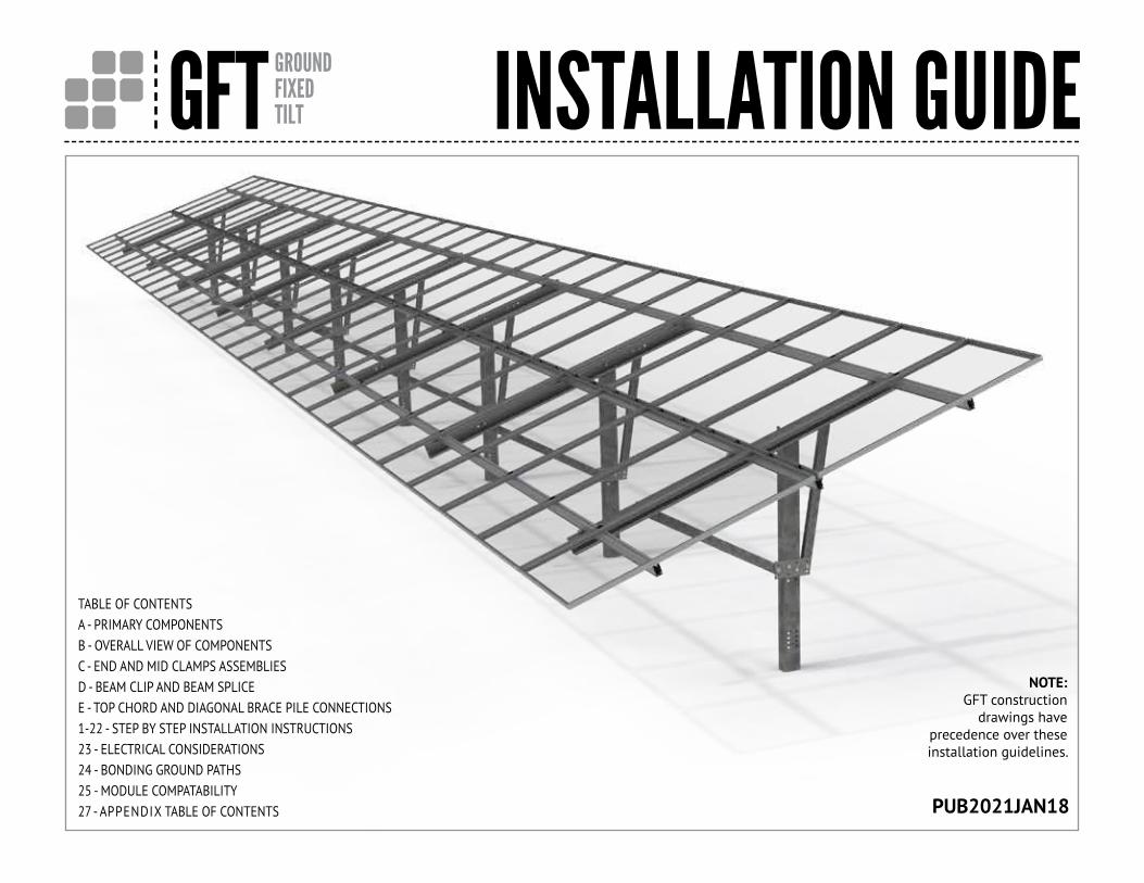
Mid Clamp Assembly with T-Bolt
C
End Clamp Assembly
Mid Clamp Assembly With T-Bolt
END & MID CLAMP ASSEMBLIES
ITEM COMPONENT MATERIAL4 3.25" x 2" East-West Aluminum Beam Aluminum Alloy 6005A-T61, 6351-T5 or 6061-T6, Fy = 35 ksi, Ftu = 38 ksi
6 Mid Clamp Aluminum Alloy 6005A-T61, 6351-T5 or 6061-T6, Fy = 35 ksi, Ftu = 38 ksi
8 PV Module (By Others) As per Manufacturer
SEE DWG 1/4-20 T-Bolt (Serrated or Non-Serrated) 300 Stainless Steel (301 Preferred) with Min Ftu = 70 ksi
SEE DWG 1/4-20 Serrated Flange Nut Stainless Steel ASTM F594 with Min Ftu = 70 ksi
ITEM COMPONENT MATERIAL4 3.25" x 2" East-West Aluminum Beam Aluminum Alloy 6005A-T61, 6351-T5 or 6061-T6, Fy = 35 ksi, Ftu = 38 ksi
5 End Clamp Aluminum Alloy 6005A-T61, 6351-T5 or 6061-T6, Fy = 35 ksi, Ftu = 38 ksi
8 PV Module (By Others) As per Manufacturer
SEE DWG #10-32 Bolt with 1/2" Hex Head 300 Stainless Steel (301 Preferred) with Min Ftu = 70 ksi
SEE DWG 1/4-20 Serrated Flange Nut Stainless Steel ASTM F594 with Min Ftu = 70 ksi
End Clamp Assembly
4
4
8
6
8
5
PRO SERIES
*See appendix for different clamp configurations.

TECHNICAL DATASHEET PAGE GFT GROUNDFIXEDTILT
ITEM COMPONENT MATERIAL4 3.25" x 2" East-West Aluminum Beam Aluminum Alloy 6005A-T61, 6351-T5 or 6061-T6, Fy = 35 ksi, Ftu = 38 ksi
17 East-West Beam Splice Insert Aluminum Alloy 6005A-T61, 6351-T5 or 6061-T6, Fy = 35 ksi, Ftu = 38 ksi
18 1/4" x 20 Self Drilling Screw (Buildex) Grade 5, ASTM A449/ SAE J429 (Similar Properties Confirmed by testing)
East-West Beam Clip
East-West Beam Splice
D
East-West Rail Clip
BEAM CLIP & BEAM SPLICE
ITEM COMPONENT MATERIAL4 3.25" x 2" East-West Aluminum Beam Aluminum Alloy 6005A-T61, 6351-T5 or 6061-T6, Fy = 35 ksi, Ftu = 38 ksi
7 Hex Flange Nut 1/4-20 Serrated 302HQ 18/8 Stainless Steel Austenitic 300 Series, Min Ftu = 85 ksi
15 Hex Bolt 1/4-20 x 1" 302HQ 18/8 Stainless Steel Austenitic 300 Series, Min Ftu = 85 ksi
16 East-West Beam Clip Aluminum Alloy 6005A-T61, 6351-T5 or 6061-T6, Fy = 35 ksi, Ftu = 38 ksi
East-West Beam Splice
4
4
18
17
I I
®
I I
I I I
4
7 15
16

TECHNICAL DATASHEET PAGE GFT GROUNDFIXEDTILT
Top Chord to Pile Connection
Top Chord to Pile Connection
Diagonal Brace Plate to Pile Connection
Diagonal Brace Plate to Pile Connection
EPILE CONNECTIONSTOP CHORD & DIAGONAL BRACE
ITEM COMPONENT MATERIAL1 4.1" Top Chord Channel Cold Rolled ASTM A653 HSLAS Grade 50 or 55
2 6" x 4.5" C-Shape Pile Cold Rolled ASTM A653 HSLAS Grade 50 or 55
10 Flat Washer 3/4" SAE Type A Narrow
12 Hex Bolt 3/4-10 x 1-1/2" SAE J429-Grade Varies per Project
14 Hex Flange Nut 3/4-10 Serrated SAE J429-Grade Varies per Project
ITEM COMPONENT MATERIAL2 6" x 4.5" C Shape Pile Cold Rolled ASTM A653 HSLAS Grade 50 or 55
3 Diagonal Brace Plate ASTM A36 or ASTM A653 GR 50 Steel
9 Flat Washer 5/8" SAE Type A Narrow
11 Hex Bolt 5/8-11 x1" SAE J429-Grade Varies per Project
13 Hex Flange Nut 5/8-11 Serrated SAE J429-Grade Varies per Project
19 Diagonal Brace Cold Rolled ASTM A653 HSLAS Grade 50 or 55
0 0
12 14
1
2
Q
0 0 0
0
0
0 0
0 0
4X 9 11 13
2
1919
3
10

GFT GROUNDFIXEDTILT INSTALLATION GUIDE PAGE
INSTALL PILES
All piles within single table must be oriented to face
the same direction per the construction drawings.
1
Hole height above grade per construction drawings.
Note: C-Piles must be installed with C open to the West.
4.5
6West

GFT GROUNDFIXEDTILT INSTALLATION GUIDE PAGE
System will accommodate a +10% E-W slope without modification.• Plumb tolerances apply regardless of slope.• Pile position tolerances apply relative to nominal finish grade line.
E-W SLOPE TOLERANCE
W E+15% Slope
-15% Slope
2
Note: The GFT system has been installed at an E-W slope of 15%. This is achievable, but requires additional effort to ensure that holes align for bolted connection.
GFT GROUNDFIXEDTILT INSTALLATION GUIDE PAGE
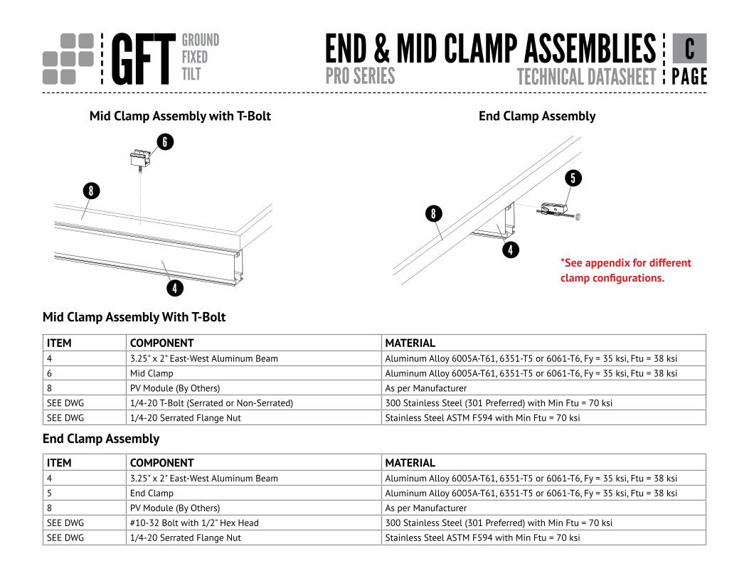
PILE POSITION & TOLERANCES
+1"
N-S+1°
Rotation +2°
E-W+1°
+ 1" E-W + 1" N-S
N
3
W

GFT GROUNDFIXEDTILT INSTALLATION GUIDE PAGE
1. Align target hole locations in all piles (within tables and table to table) using laser or string line.
2. Determine if adjustments are needed up or down (hole patterns allow for + 1-1/2" adjustments in 3/4" increments per instruction on following pages).
3. Mark holes to be used for top chord and diagonal brace plate attachments prior to installing.
The system is capable of being aligned to the target string or laser line using the adjustment holes when piles are placed within allowable tolerances. Each table will however accommodate a 2% deviation from the target line as shown without impact to structural integrity.
ALIGN ATTACHMENT HOLES ON PILES
+2%_
4
+2%

GFT GROUNDFIXEDTILT INSTALLATION GUIDE PAGE
ATTACH TOP CHORD TO PILE
Install hardware snug tight. Torque per construction drawings after final adjustments.
3/4" Serrated Flange Nut
3/4" Flat Washer
3/4" x 1-1/2" Hex Bolt
Target HeightHoles
5

GFT GROUNDFIXEDTILT INSTALLATION GUIDE PAGE
TOP CHORD TO PILE ADJUSTMENT
Top Chord
Target Hole
Target Hole
Pile
Move top chord up or down (not horizontally) as needed to adjust height in 3/4" increments.
Use single 3/4" bolt (nut and washer) at one of the locations shown.
Target Height
Up 3/4"
Down 3/4"
Up 1-1/2"
Down 1-1/2"
Adjustment Locations (Single 3/4" Bolt)
Target Height
6

GFT GROUNDFIXEDTILT INSTALLATION GUIDE PAGE
DIAGONAL BRACE ASSEMBLY
Install hardware snug tight. Torque per construction drawings after final adjustments.
(2) 5/8" Serrated
Flange Nuts
Target Height Holes
(2) 5/8" x 1" Hex Bolts
(2) 5/8" Flat Washers
Diagonal Brace Assembly
7ATTACH PILE TO

GFT GROUNDFIXEDTILT INSTALLATION GUIDE PAGE
PILE ADJUSTMENT
Move diagonal brace plate up or down (not horizontally) as needed toadjust height in 3/4" increments.
Use pair of 5/8" bolts (nuts and washers) at location shown.
Adjustment Locations (Pair of 5/8" Bolts)
Up 3/4"
Down 3/4"
Diagonal Brace Plate
Pile
Target Holes
Target Height
Target Height
Up 1-1/2"
Down 1-1/2"
8DIAGONAL BRACEASSEMBLY TO

GFT GROUNDFIXEDTILT INSTALLATION GUIDE PAGE
ATTACHMENT TO TOP CHORD
Install hardware snug tight. Torque per construction drawings after final adjustments.
Rear Diagonal Brace
5/8" Serrated Flange Nut
Target Holes5/8" Flat Washer
5/8" x 1" Hex Bolt
9DIAGONAL BRACE
Front Diagonal Brace

GFT GROUNDFIXEDTILT INSTALLATION GUIDE PAGE
INSTALLATION ON ALL PILESTorque all bolts after final adjustments. Refer to Torque values stated on page B of theinstallation manual and in the general notes section of the construction drawings.
10REPEAT TOP CHORD & DIAGONAL BRACE
UL2703 CERTIFICATION MARKING LABEL
Unirac Ground Fixed Tilt (GFT) is listed to UL 2703. Certification marking is embossed on all mid clamps as shown. Labels with additional information will be provided . After the racking system is fully assembled, a single label should be applied onto the GFT rail at the edge of the array.
Note: The sticker label should be placed such that it is visible, but not outward facing.

GFT GROUNDFIXEDTILT INSTALLATION GUIDE PAGE
TOP CHORD TILT ADJUSTMENT
If required, additional minor adjustment of top chord angle may be achieved by a combined repositioning of diagonal braces to adjacent holes in top chord and diagonal brace plate.
DETAIL 20° - GSCALE 1 / 2
DETAIL 20° - HSCALE 1 / 2
DETAIL 20° - JSCALE 1 / 2
DETAIL A 20°SCALE 1 / 2
DETAIL B 20°SCALE 1 / 2
DETAIL C 20°SCALE 1 / 2
DETAIL D 30°SCALE 1 / 2
DETAIL E 30°SCALE 1 / 2DETAIL F 30°
SCALE 1 / 2
20° - G
20° - H
20° - J
A 20°
B 20°
C 20°
D 30°
E 30°
F 30°
30°
20°
30°
DETAIL 20° - GSCALE 1 / 2
DETAIL 20° - HSCALE 1 / 2
DETAIL 20° - JSCALE 1 / 2
DETAIL A 20°SCALE 1 / 2
DETAIL B 20°SCALE 1 / 2
DETAIL C 20°SCALE 1 / 2
DETAIL D 30°SCALE 1 / 2
DETAIL E 30°SCALE 1 / 2
DETAIL F 30°SCALE 1 / 2
20° - G
20° - H
20° - J
A 20°
B 20°
C 20°
D 30°
E 30°
F 30°
30°
20°
30°
DETAIL 20° - GSCALE 1 / 2
DETAIL 20° - HSCALE 1 / 2
DETAIL 20° - JSCALE 1 / 2
DETAIL A 20°SCALE 1 / 2
DETAIL B 20°SCALE 1 / 2
DETAIL C 20°SCALE 1 / 2
DETAIL D 30°SCALE 1 / 2
DETAIL E 30°SCALE 1 / 2
DETAIL F 30°SCALE 1 / 2
20° - G
20° - H
20° - J
A 20°
B 20°
C 20°
D 30°
E 30°
F 30°
30°
20°
30°
DETAIL 20° - GSCALE 1 / 2
DETAIL 20° - HSCALE 1 / 2
DETAIL 20° - JSCALE 1 / 2
DETAIL A 20°SCALE 1 / 2 DETAIL B 20°
SCALE 1 / 2
DETAIL C 20°SCALE 1 / 2
DETAIL D 30°SCALE 1 / 2
DETAIL E 30°SCALE 1 / 2
DETAIL F 30°SCALE 1 / 2
20° - G
20° - H
20° - J
A 20°
B 20°
C 20°
D 30°
E 30°
F 30°
30°
20°
30°
11

GFT GROUNDFIXEDTILT INSTALLATION GUIDE PAGE
1. Align target hole locations using laser or string line.
2. Determine if adjustments are needed up or down. (hole patterns allow for +1" adjustment in 1/2" increments per instruction on following pages).
3. Mark holes to be used for attaching E-W beams prior to installing.
Target beam clamp holes
12HOLELOCATIONS E-W BEAM TO TOP CHORD
The shared rail system requires special atention to the center E-W beam. If this center beam is aligned properly, the entire table can be installed straight and square.
* *

GFT GROUNDFIXEDTILT INSTALLATION GUIDE PAGE
E-W BEAM CLIPS TOP CHORDS
Install lower clip at target holes identified in previous step
Leave loose for attachment to E-W beam
13INSTALLATIONOF
Install clips to top chords on low sides of beams only
Anti-SeizeStainless steel hardware can seize up, a process called galling. To significantly reduce its likelihood: 1. Apply minimal lubricant to bolts only where indicated in installation process, preferably Anti-Seize commonly found at auto parts stores (Anti-seize has been factory applied to mid clamp bolts) 2. Shade hardware prior to installation, and 3. Avoid spinning stainless nuts onto bolts at high speed.

GFT GROUNDFIXEDTILT INSTALLATION GUIDE PAGE
INSTALL E-W BEAMS 14
Install center E-W beam starting at either end of table.(Proper alignment of this center beam is crucial for a straight and square installation)

GFT GROUNDFIXEDTILT INSTALLATION GUIDE PAGE
ATTACH E-W BEAMS TO TOP CHORDS
1. Position E-W Beam
3. Install upper clips and hardware
4. Torque bolts per construction drawings
Rotational adjustment to align top chords may be made prior to tightening beam clamps
Note: Note: Allowable spans and cantilevers are project specific - please contact Unirac or refer to U-Builder
Set beam E-W position per construction drawings
15
2. Insert lower clip into beam slot

GFT GROUNDFIXEDTILT INSTALLATION GUIDE PAGE
INSTALL E-W BEAM SPLICES
Insert splices into ends of installed E-W beams.
Insert splice to half of splice length (~12")
* Install self-tapping screw through one wall of beam and splice
Slide next E-W beam on to splice
5" to 7"
No Gap
5" to 7"
Centerline +1"
*Install self-tapping screw
* Self-tapping screws may be installed on either side (N or S) of the E-W beam
16

GFT GROUNDFIXEDTILT INSTALLATION GUIDE PAGE
E-W BEAM INSTALLATION 17COMPLETE

GFT GROUNDFIXEDTILT INSTALLATION GUIDE PAGE
INSTALL MODULE W/PRO SERIES CLAMPS
Rotate bolt into position
Insert T-bolt into rail
18PRO SERIES
INSTALL END CLAMPS ON RAIL:Slide end clamp on to rail byengaging the two t-guide brackets with the top slot of the rails. Ensure bolt is extended as far as possible so that clamp is positioned at max.distance from end of rail.
POSITION END CLAMPS:Slide end clamp assembly on to rail until bolt head engages with end of rail. End clamps are positioned onrails prior to the first end module and prior to the last end module.
NOTE: To assist insertion of clamp intorail slot, Pressure may be applied totop or side of bracket as shown. Donot force clamp into rail by pushingon bolt with excessive force.
See appendix for Standard Clamps and UAF clamps.
INSTALL FIRST MODULE: Install the first end module onto rails with the flange of the module frame positioned between end clamps an ends of rails.
ENGAGE CLAMP: While holding module in position and with flange in full contact with rail, rotate end clamp bolt until clamp engages with flange to provide clamp force. To ensure bolt is not over-torqued, use low torque setting on drill or If using an impact driver, stop rotation as soon as impact action of driver begins. TORQUE VALUE (See table and notes on PG. 1) End clamp bolt to 5 ft-lbs, No anti-seize
Position module flush with ends of rails. Rails should not extend more than 1/2" beyond module. Module must be fully supported by rails and cannot overhang ends of rails.
*
*

GFT GROUNDFIXEDTILT INSTALLATION GUIDE PAGE
INSTALL PRO SERIES CLAMPS ON 1ST MODULE
Insert T-bolt into E-W Beam
Rotate bolt into position
Position clamp on module. Do not tighten nut until next module is in place.
19
Install Mid Clamps(Position upright against module but do not torque)
PRO SERIES
Verify that bolt position indicator is perpendicular to E-W beam once nut is torqued
See appendix for Standard Clamps and UAF clamps.

GFT GROUNDFIXEDTILT INSTALLATION GUIDE PAGE
MODULES
1. Place module on rails and engage with Mid Clamps
2. Align and square modules
3. Verify Mid Clamp bolt shafts are perpendicular to E-W Beam.
4. Torque nuts
5. Repeat installation of clamps and modules
(Stagger the install of modules; lower-upper and repeat)
6. Install End Clamps on last module
20INSTALLATION OF
6
1
2
4
5
3
NOTE: The GFT system must be periodically re-inspected for loose components, loose fasteners and any corrosion, such that if found, the affected components are to be immediately replaced.

GFT GROUNDFIXEDTILT INSTALLATION GUIDE PAGE
MODULE INSTALLATION JIG 21
5A
5
1
2
3
4
5C
5B
1. Place 1st lower module. Align with center E-W Beam. 2. Place upper module. Align and square. Install Mid Clamp and End Clamps3. Once Mid Clamp (4) are placed in the rails align lower module and support with Jig (see item 5).4. Add upper module. Align and install – tighten Mid Clamps.5. Module installation Jig – This can be built on-site using the following material:
A: E-W BeamB: L-Foot w/ 3/8" T-Bolt and serrate flange nut – installed in side slotC: L-Foot w/ 1/4" T-Bolt or Hex Bolt and serrated flange nut – installed in top slot

GFT GROUNDFIXEDTILT INSTALLATION GUIDE PAGE
MODULES 22COMPLETEINSTALLATION OF

GFT GROUNDFIXEDTILT INSTALLATION GUIDE PAGE
ELECTRICAL CONSIDERATIONS
The entire Unirac GFT table has been classified for grounding & bonding to UL2703. The bonding path has been evaluated from the PV module frame all the way through to the pile. The following are suggestions to aid in grounding of the table for the project electrical engineer of record, and by the local authority having jurisdiction.
This racking system may be used to ground and/or mount a PV module complying with UL1703 only when the specific module has been evaluated for
grounding and/or mounting in compliance with the included instructions.
GROUND LUG MOUNTING DETAILSDetails are provided for both the WEEB and Ilsco products. The WEEBLug has a grounding symbol located on the lug assembly. The Ilsco lug has a green colored set screw for grounding indication purposes. One lug is recommended per GFT table. Installation must be in accordance with NFPA NEC70, however the electrical designer of record should refer to the latest revision of National Electrical Code (NEC) for actual grounding conductor cable size. Unirac GFT is intended to be used with PV modules that have a system voltage less than or equal to voltage less than or equal to that allowable by NEC. A minimum 10AWG, 105°C copper grounding conductor should be used to ground the system according to the (NEC)
and the authority having jurisdiction. It is the installers responsibility to check local codes, which may vary. NOTE: Any holes drilled to attach the ground lugs should be de-burred before use. NOTE: All Unirac module clamps and the llsco GBL-4DBT ground lug are single use. All other GFT components are multiple use.
TEMPORARY BONDING CONNECTION DURING ARRAY MAINTENANCEWhen removing modules for replacement or system maintenance, any module left in place that is secured with a bonding mid-clamp will be properly grounded. If a module adjacent to the end of a row is removed, or if any other maintenance condition leaves a module without a bonding mid clamp, a temporary bonding connection must be installed as follows:• Attach Ilsco GBL-4DBT or WeebLug 6.7 to both modules on either side of the module that has been removed. Note: The lug should be attached to the manufacturers designated grounding point on the frame. • Install a solid #6 AWG copper wire to both grounding lugs.
NOTE: ISOLATE COPPER FROM ALUMINUM CONTACT TO PREVENT CORROSION.
The following grounding & bonding components have been certified to be compatible with Unirac GFT:• Wiley WEEBLug (P/N 0080025) Torque 1/4"
mounting hardware to 10ft-lbs. See product data sheet for conductor size and conductor fastener torque.
• Ilsco Lay-in Lug (P/N GBL-4DBT) Torque 10-32 mounting hardware to 2.9ft-Lbs (35in-Lbs). See product data sheet for conductor size and conductor fastener torque.
Ground LugWEEBLugIlsco
Bolt size1/4"-20#10-32
Drill size17/64"13/64"
23
Steel C-Shape Pile
NOTE: Details are provided for both the WEEB and Ilsco products
WEEBLug 6.7 Ground LugUNIRAC P/N:0080025
Ilsco GBL-4DBT Ground LugNOTE: Is for single use only

GFT GROUNDFIXEDTILT INSTALLATION GUIDE PAGE
BONDING CONNECTION GROUND PATHS 24
TEMPORARY BONDING CONNECTION DURING ARRAY MAINTENANCE
When removing modules for replacement or system maintenance, any module left in place that is secured with a bonding Midclamp will be properly grounded. If a module adjacent to the end module of a row is removed or if any other maintenance condition leaves a module without a bonding mid clamp, a temporary bonding connection must be installed as shown• Attach Ilsco SGB4 to wall of GFT rail (Rail shown in picture is not a GFT rail but a representative rail for demonstration only)• Attach Ilsco SGB4 to module frame• Install solid #6 AWG copper wire jumper to Ilsco
lugs
Ilsco SGB-4
Ilsco SGB-4
Ilsco SGB-4
SOLID COPPER WIRE
ELECTRICAL CONSIDERATIONS
GFT is intended to be used with PV modules that have a system voltage less than or equal to that allowable by NEC. For standard system grounding a minimum 10AWG, 105°C copper grounding conductor should be used to ground a system, according to the National Electric Code (NEC). It is the installer’s responsibility to check local codes, which may vary. See below for interconnection information.
INTERCONNECTION INFORMATION
There is no size limit on how many GFT & PV modules can be mechanically interconnected for any given configuration, provided that the installation meets the requirements of applicable building and fire codes.
GROUNDING NOTES
The installation must be conducted in accordance with the National Electric Code (NEC) and the authority having jurisdiction. Please refer to these resources in your location for required grounding lug quantities specific to your project.
The grounding / bonding components may overhang parts of the array so care must be made when walking around the array to avoid damage.
Conductor fastener torque values depend on conductor size. See product data sheets for correct torque values.
Mid clamps do not need to be repositioned for re-use.
BONDING MIDCLAMP ASSEMBLY
NOTE: All Unirac mid clamps and the UAF end clamp shown in this install guide are bonding clamps
REQUIRED ONLY FOR TEMPORARY BONDING DURING ARRAY MAINTENANCE
Aluminum mid clamp with stainless steel bonding pins that pierce module frame anodization to bond module to module through clamp
Stainless steel nut bonds aluminum clamp to stainless steel T-bolt
Serrated T-bolt head penetrates rail anodization to bond T-bolt, nut, clamp, and modules to SM rail
1
2
3
1
2
3

GFT GROUNDFIXEDTILT INSTALLATION GUIDE PAGE
MODULE COMPATIBILITY 25BONDING & GROUNDING APPROVED
• The frame profile must not have any feature that might interfere with the bonding devices that are integrated into the racking system• Use with a maximum over current protection device OCPD of 30A
The modules selected for UL 2703 bonding and grounding testing represent the broadest possible range of modules on the market. The tests were performed for each specific bonding location using representative module frame profile sections. The tests performed cover the following basic module parameters:
Electrical Bonding and Grounding Test ModulesThe list below is not exhaustive of compliant modules but shows those that have been evaluated and found to be electrically compatible with the GROUND FIXED TILT system.
Aleo P-Series & S-Series
Aptos Solar DNA-144 & DNA 120 Series
Astronergy
CHSM6612 M, M/HVCHSM6612P SeriesCHSM6612P/HV SeriesCHSM72M-HC,
Auxin
AXN6M610T, AXN6P610T, AXN6M612T AXN6P612T
Axitec AXI Power, AXI Premium, AXI Black Premium
Boviet BVM6610, BVM6612
BYD P6K & MHK-36 Series
Canadian Solar
CS6P-M, CS6P-P, CSX-P, CS6X-P, CS5A-M, CS6U-P, CS6U-M, CS6K-MS, CS6K-M, CS6K-P,ELPS CS6A-MM, ELPS CS6P-MM, CS3U-P, CS3U-MS, CS3K-P, CS3K-MS, CS1K-MS, CS3K-MB, CS3K-PB, CS3U-MB, CS3W-P, CS3L-P, CS3U-PB, CS1H-MS, CS3U-MS, CS3U-PB-AG,CS3U-MB-AG, CS3K-PB-AG, CS3K-MB-AG, CS3W-P-PB-AG, CS1H-MS, CS1U-MS,CS3U-P HE, CS3K-P HE, CS6U-P HE,CS6K-P HE, CS6K-MS AllBlack,ELPS CS6P-MM, ELPS CS6A-MM
Centrosolar America C-Series & E-Series
CertainTeedCT2xxMxx-01, CT2xxPxx-01, CTxxxMxx-01, CTxxxPxx-01, CTxxxMxx-02, CTxxxMxx-03CTxxxMxx-04, CTxxxHC11-04
Eco Solargy Orion 1000 & Apollo 1000
ET Solar ET AC Module, ET Module
Manufacture Module Model / Series
Flextronics FXS-xxxBB
GCL GCL-P6 & GCL-M6 Series
Hanwha SolarOne HSL 60
HansolTD-AN3, TD-AN4, UB-AN1, UD-AN1
Heliene 36M, 36P 60M, 60P, 72M & 72P Series
HT Solar
HT72-156(M/P),HT72-156P-C, HT72-156P(V)-CHT72-156M(PDV)-BF, HT72-156M(PD)-BFHT60-156M-C,HT60-156M(V)-C
Hyundai KG, MG, RW, TG, RI, RG, TI, KI, HI Series
ITEK iT-SE Series
Japan Solar JPS-60 & JPS-72 Series
JA Solar
JAP6 60-xxx, JAM6(K)-60/xxx, JAP6(k)-72-xxx/4BB, JAP72SYY-xxx/ZZ,JAP6(k)-60-xxx/4BB, JAP60SYY-xxx/ZZ, JAM6(k)-72-xxx/ZZ, JAM72SYY-xxx/ZZ,JAM6(k)-60-xxx/ZZ, JAM60SYY-xxx/ZZ.i. YY: 01, 02, 03, 09, 10ii. ZZ: SC, PR, BP, HiT, IB, MWYY = Backsheet, ZZ Cell technology
Jinko JKM & JKMS Series
Kyocera KD-F & KU Series
LG Electronics
N1C-G4, N1K-G4, N2W-G4, S1C-G4,S2W-G4, N1C-A5, N1K-A5, N2W-A5, N2T-A5, E1C-A5, Q1C-A5, Q1K-A5, S1C-A5, S2W-A5,N1K-V5, E1K-A5, N1K-V5, N1C-V5, Q1C-V5,N2W-V5, N1K-V5, N1K-L5, N1C-N5, M1C-N5N2T-J5, N2W-B3, N2W-L5
LONGi
LR4-60HPH, LR4-72HPH, LR4-72HBD, LR6 - 72HV, LR6 -60, LR6 -60HV, LR6 -60PH, LR6 -72, LR6 -72PH, LR6-60BK, LR6-60PB, LR6-60PE, LR6-72BK, LR6-72PB, LR6-72PE, LR6-72HBD RealBlack LR4-60HPB, RealBlack LR6-60HPB,
Mission Solar EnergyMSE Mono, MSE Perc
Mitsubishi MJE & MLE Series
Neo Solar Power Co. D6M Series
Panasonic
VBHNxxxSA06/SA06B/SA11/SA11BVBHNxxxSA15/SA15B/SA16/SA16B,VBHNxxxKA, VBHNxxxKA03/04,VBHNxxxSA17/SA17G/SA17E/SA18/SA18E,VBHNxxxZA01/ZA02/ZA03/VBHNxxxZA04,EVPV
Peimar SGxxxM (FB/BF)
Phono Solar
PSxxxM1-20/UPSxxxM1H-20/UPSxxxM1-20UHPSxxxM1H-20UHPSxxxM1-20/UHPSxxxM1H-20/UHPSxxxM-24/TPSxxxMH-24/TPSxxxM-24/THPSxxxMH-24/TH
Q.Cells
Plus, Pro, Peak, G3, G4, Peak G5(SC) , G6(+)(SC)(AC), G7, G8(+),Plus, Pro, Peak L-G2, L-G4, L-G5Peak L-G5, L-G6, L-G7, L-G8(BFF)
Manufacture Module Model / Series Manufacture Module Model / Series

GFT GROUNDFIXEDTILT INSTALLATION GUIDE PAGE
MODULE COMPATIBILITY 26BONDING & GROUNDING APPROVED
The modules selected for UL 2703 bonding and grounding testing represent the broadest possible range of modules on the market. The tests were performed for each specific bonding location using representative module frame profile sections. The tests performed cover the following basic module parameters.
Electrical Bonding and Grounding Test ModulesThe list below is not exhaustive of compliant modules but shows those that have been evaluated and found to be electrically compatible with the GROUND FIXED TILT system.
Manufacture Module Model / SeriesManufacture Module Model / Series Manufacture Module Model / Series
REC
RECxxxTP72, RECxxxTPRECxxxPE72, RECxxxPERECxxxTP2S(M)72, RECxxxTP2 BLK2, RECxxxTP2(M)RECxxxNP (N-PEAK)RECxxxAA(BLK)
Renesola All 60-cell modules
Risen RSM Series
S-Energy SN72 & SN60 Series
Seraphim SEG-6 & SRP-6 Series
Sharp NU-SA & NU-SC Series
SilfabSLA-M, SLA-P, SLG-M, SLG-P & BC SeriesSIL - ML, NL, BL, NT Series
Solaria PowerXT
Solartech STU HJT, STU PERC & Quantum PERC
SolarWorld Sunmodule Protect, Sunmodule Plus/Pro
Suntech STP
Suniva MV Series & Optimus Series (35mm)
Sun Edison F-Series, R-Series
SunPower AC, X-Series, E-Series & P-Series
TalesunTP572, TP596, TP654, TP660, TP672, Hipor M, Smart
Tesla SC, SC B, SC B1, SC B2
TrinaPA05, PD05, DD05, DD06, DE06PD14, PE14, DD14, DE14, DE15
TSMC TS-150C2 CIGSw
Upsolar UP-MxxxP, UP-MxxxM(-B)
URED7MxxxH8A, D7KxxxH8A, D7MxxxH7A, D7KxxxH7A
Vikram Eldora, Somera, Ultima
Vina
VNS-72M1-5-xxxW-1.5,VNS-72M3-5-xxxW-1.5, VNS-144M1-5-xxxW-1.5, VNS-144M3-5-xxxW-1.5, VNS-120M3-5-xxxW-1.0
Winaico WST & WSP Series
Yingli YGE & YLM Series
PAGE GFT GROUNDFIXEDTILT
APPENDIX – TABLE OF CONTENTS 27
Appendix Table of ContentsAppendix A INSTALLING WITH STANDARD CLAMPSAppendix B INSTALLING WITH UNIVERSAL AF CLAMPS

PAGE GFT GROUNDFIXEDTILT
Mid Clamp Assembly with T-Bolt
28
End Clamp Assembly With T-Bolt
Mid Clamp Assembly With T-BoltITEM COMPONENT MATERIAL4 3.25" x 2" East-West Aluminum Beam Aluminum Alloy 6005A-T61, 6351-T5 or 6061-T6, Fy = 35 ksi, Ftu = 38 ksi
18 Standard Mid Clamp Stainless Steel, 301,302, or 304, 1/4 Hard, Mill Finish
19 PV Module (By Others) As per Manufacturer
SEE DWG 1/4-20 T-Bolt (Serrated or Non-Serrated) 300 Stainless Steel (301 Preferred) with Min Ftu = 70 ksi
SEE DWG 1/4-20 Serrated Flange Nut Stainless Steel ASTM F594 with Min Ftu = 70 ksi
ITEM COMPONENT MATERIAL4 3.25" x 2" East-West Aluminum Beam Aluminum Alloy 6005A-T61, 6351-T5 or 6061-T6, Fy = 35 ksi, Ftu = 38 ksi
17 Standard End Clamp Stainless Steel, 301,302, or 304, 1/4 Hard, Mill Finish
19 PV Module (By Others) As per Manufacturer
SEE DWG 1/4-20 T-Bolt (Serrated or Non-Serrated) 300 Stainless Steel (301 Preferred) with Min Ftu = 70 ksi
SEE DWG 1/4-20 Serrated Flange Nut Stainless Steel ASTM F594 with Min Ftu = 70 ksi
End Clamp Assembly with T-Bolt
M301XX: T-BOLT 1/4-20 ORM302XX: T-BOLT SERR. 1/4-20
4
17
19
M301XX: T-BOLT 1/4-20 ORM302XX: T-BOLT SERR. 1/4-20ARE ACCEPTABLE
4
19
18
APPENDIX A STANDARD CLAMPS END & MID CLAMP ASSEMBLIES

PAGE GFT GROUNDFIXEDTILT
Rotate bolt into position
Insert T-bolt into rail
Install End Clamps* Refer to construction drawings or module installation guidelines for module mounting locations and limits.
Install End Module• Place module on E-W Beams• Engage module with end clamps• Align and square module• Torque nuts to 10ft-lbs
Serrated T- Bolts Non-Serrated T- Bolts
Verify that bolt position indicator
is perpendicular to E-W beam
Verify that bolt position indicator
is as shown
DETAIL CSCALE 1 : 1
DETAIL DSCALE 1 : 1
C
D
1/2" min
*
*
29APPENDIX A STANDARD CLAMPS INSTALL MODULE W/END CLAMPS

PAGE GFT GROUNDFIXEDTILT
DETAIL DSCALE 1 : 1
Insert T-bolt into E-W Beam Rotate bolt
into position
Position clamp on module. Do not tighten nut until next module is in place.
30
Verify that bolt position indicator
is perpendicular to E-W beam
Verify that bolt position indicator
is as shown
Serrated T- Bolts Non-Serrated T- BoltsInstall Mid Clamps(Position upright against module but do not torque.) When ready - torque to 10ft-lbs.
APPENDIX ASTANDARD MID CLAMPS INSTALL MID CLAMPS ON 1ST MODULE

PAGE GFT GROUNDFIXEDTILT
Rotate bolt into position
Insert T-bolt into rail
Install End Clamps* Refer to construction drawings or module installation guidelines for module mounting locations and limits.
Install End Module• Place module on E-W Beams• Engage module with end clamps• Align and square module• Torque nuts to 15ft-lbs
Serrated T- Bolts
Verify that bolt position indicator
is perpendicular to E-W beam
1/2" min
31APPENDIX BUNIVERSAL AF CLAMPS INSTALL MODULE W/END CLAMPS
DETAIL CSCALE 1 : 1
DETAIL DSCALE 1 : 1
C
D
UAF End Clamp
UAF End Clamp
UAF End Clamp

PAGE GFT GROUNDFIXEDTILT
Position clamp on module. Do not tighten nut until next module is in place.
32
Verify that bolt position indicator
is perpendicular to E-W beam
Serrated T- Bolts
Install Mid Clamps(Position upright against module but do not torque.) When ready - torque to 15ft-lbs.
APPENDIX BUNIVERSAL AF CLAMPS INSTALL MID CLAMPS ON 1ST MODULE
NOTE: UAF Mid Clamps may NOT be used on shared rail. Use standard mid clamps when installing on a shared rail.
UAF Mid Clamp
UAF Mid Clamp
Standard Mid Clamps
Insert T-bolt into E-W Beam
Rotate bolt into position


![GFT Thermico Horizontal · 2018. 4. 5. · GFT Thermico® Horizontal Gasser Fassadentechnik AG T +4171/2824000 F +4171/2824001 1.02-GFT Konsole Thermico® Horizontal [G1] GFT console](https://static.fdocuments.in/doc/165x107/601904884ff78d65134a4541/gft-thermico-horizontal-2018-4-5-gft-thermico-horizontal-gasser-fassadentechnik.jpg)