GFS·l SOLDIER WALL FORMWDRK - scaffcouae.com - GFS SOLDIER WALL.pdfaccording to report no. 108 of...
9
Transcript of GFS·l SOLDIER WALL FORMWDRK - scaffcouae.com - GFS SOLDIER WALL.pdfaccording to report no. 108 of...


® GFS· l SOLDIER WALL FORMWDRK
GFS-1 SOLDIER WALL FORMWORK
LIFTING BRACKET
SCAFFOLD BOARD
UNIVERSAL CLAMP
PLYWOOD FACE (TO BE PROVIDED BY CONTRACTOR)
ACCESS BRACKET & HANDRAIL POST
DOUBLE PUSH PU LL PROPS
DYWIDAG (TIE SYSTEM)
ALUMINUM WALERS/ TIMBER WALERS
GFS·l SOLDIER WALL FORMWORK ®
GFS-1 SOLDIER SYSTEM

® GFS· l SOLDIER WALL FORMWORK
GFS-1 SOLDIER SYSTEM: STANDARD SIZES
LENGTH (M) 1.2
WEIGHT (KG) 26.48 II ------IL_ 2.7
48.05
--,,--.-----' 3.0 :=======l
57.87 -----·~ -3.6
63.14
GFS-1 SOLDIER SYSTEM: MAKE UP OF LONGER SECTIONS A unique feature of the GFS-1 Soldier System is the high strength connection that can be made between sold iers by use of the jo int plate. This is particu lar ly important where t ies through the concrete must be kept to the m inimum . In less critica l situations simple bolt ing can be used as an alternative.
END-TO-END FITTING WITH JOINT PLATE A very strong connection resu lting in savings in the number of t ies required can be made w ith the unique Jo int Plate. Soldiers are butted end-to-end and connected using the Joint Plate for HT pins and eight spring clips. The moment of the j oint must not exceed 17 .80KNM (70 percent of moment resistance of the sold ier).
JOINT PLATE Supplied complete w ith four ( 4) HT pins.
END-TO-END FITTING WITH SET SCREWS Soldiers are butted end-to-end and secured us ing four ( 4) M 16 x 35mm set screws and nuts fixed t hrough the holes in the end plates. The moment at t he j oint must not exceed 5kNm (20 percent of moment resistance of t he sold ier).
SET SCREWS
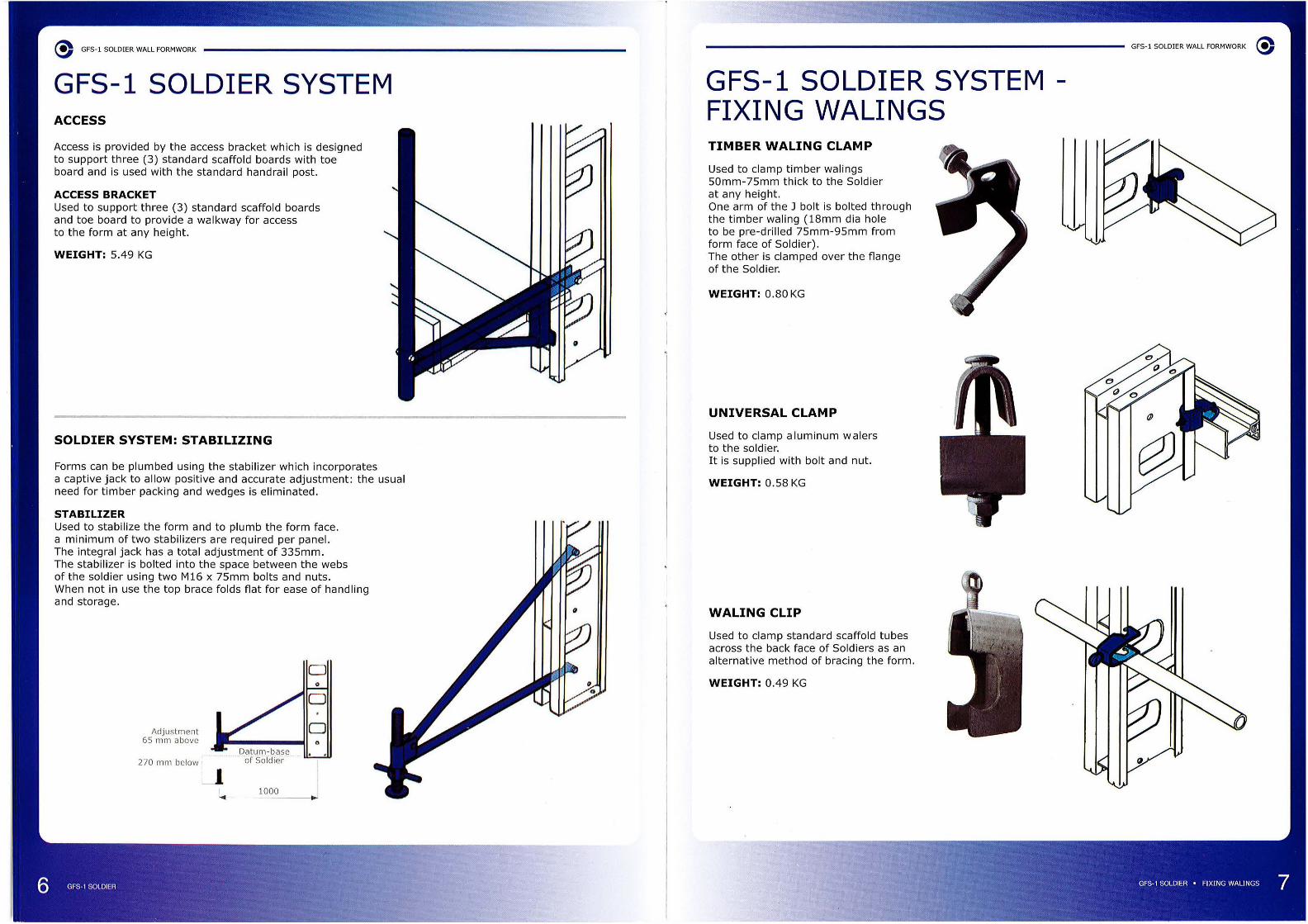
GFS- 1 SOLDIER SYSTEM ACCESS
Access is provided by the access bracket which is designed to support three (3) standard scaffold boards with toe board and is used with the standard handrail post.
ACCESS BRACKET Used to support three (3) standard scaffold boards and toe board to provide a wa lkway for access to the form at any height.
WEIGHT: 5.49 KG
SOLDIER SYSTEM: STABILIZING
Forms can be plumbed using the st abi lizer which incorporates a captive jack to allow pos itive and accurate adjustment: the usua l need for timber packing and wedges is eliminated.
STABILIZER Used to stabilize the form and to plumb the form face. a minimum of two stab ilizers are required per panel. The integral jack has a total adjustment of 335mm. The stab ilizer is bolted into t he space between the webs of the so ldier using two M16 x 75mm bolts and nuts. When not in use the top brace fo lds flat for ease of handling and storage.
Adjustment 65 mm above
270 mm below ~· Datum-base .. of Soldier . ..
L,. ___ 1000
D
GFS-1 SOLDIER SYSTEM FIXING WALINGS TIMBER WALING CLAMP
Used to clamp timber wa lings 50mm-75mm t hick to the Soldier at any height . One arm of the J bolt is bolted th rough the timber wa ling (18mm dia hole to be pre-drilled 75mm-95mm from form face of Sold ier). The other is clamped over t he flange of the Soldier.
WEIGHT: 0.80 KG
UNIVERSAL CLAMP
Used t o clamp aluminum wa lers t o t he soldier. It is supplied with bolt and nut.
WEIGHT: 0.58 KG
WALING CLIP
Used to clamp standard scaffo ld tubes across the back face of Soldiers as an alternative method of bracing the form.
WEIGHT: 0.49 KG
GFS-1 SOLDIER WALL FORMWORK ®

® GFS-1 SOLDIER WALL FORMWORK
GFS-1 SOLDIER SYSTEM DESI GN DATA The design data of GFS- 1 so ldier permits ties to be positioned at any height.
Two solutions are detailed below, the first is with ties at the top and bottom of the so ldier to allow the top tie to be above concrete level, the second is with the ties spaced to ba lance the pos itive and negative moments in the soldier and al low maximum spacing.
CONCRETE PRESSURE SHOULD BE CALCULATED
TECHNICAL PROPERTIES OF THE SOLDIER
Moment of resistance 25.SkNm
Maximum allowable end rea ction 55.0kN
Moment of inertia
Modulus of section 163cm3
Max. tie load at intermediate position 80kN ---ACCORDING TO REPORT NO. 108 OF F.ORMWORK LOADING DESIGN SHEET OF CIRIA,
• ,n -----. D D
•,n D D 1.65 M •,n D D I D D
I D I D D D D D
1.30 M D D D D 1.05 M D D .,n1 3.50 M D D D D D D
2.90 M .,,n ... Tl
D D D D D D
D 2.60 M
D D D D D
D D D D D D
D D D D D .... ... D D D D I 0.45 M D t o.45 M
.,,T2 .,,T2 .,, T2 'f T2 T T2
TIES AT HEAD AND FOOT TIES AT BALANCE POINTS
SOLDIER SPACING AND TIE LOADS
CONCRETE PRESSURE FORM HEIGHT .
WSJ!WAl,i!WAIMWWSJ!WAl,i!WW!W 20kN/ m2 SO LDIER SPACING 1.61M I 1.28M 0.86M 2.92M 2.12M 1.32M
TIE LOADS 29.9kN I 27.4kN 23.5kN 75.0kN 71.7kN 62 .2kN
40, 5kN 36.0kN 29.6kN 52.6kN 33.3kN 18 .9kN
30kN/m2 SO LDIER SPACING 1.18M 0. 92M 0.60M 2.22M 1.73M 1.29M
27.4kN 25.lkN 21.7kN 68.0kN 72.4kN 79 .0kN
42.3kN 37.3kN 30.3kN 63.5kN 45.7kN 19 .8kN
TIE LOADS ~===:. ..
!.=:.=====a!-40kN/m2 SO LDIER S PACING 1.0 lM 0.76M 0.49M 1.67M 1.49M 1.02M
TIE LOADS 26.0kN 23.7kN 20.4kN 53.7kN 67.8kN 71.lkN ~= 45.3kN 39.4kN 31.4kN 63.8kN 55.3kN 38.0kN ~= 0.95M 0. 70M 0.43M 1.55M 1.43M 0.90M 50kNi m2 SOLDIER SPACING
TIE LOADS 25.5kN 23.0kN 19.5kN 50.0kN 67.8kN 67.0kN
48.6kN 42.lkN 33.0kN 71.0kN 65.4kN 44. l kN
60kN/ m2 SO LDIER SPAC ING 0.94M 0. 68M 0.40M 1.54M 1.40M 0 .88M
TIE LOADS 25.4kN 22.8kN 19.lkN 48.6kN 67.2kN 66.5kN
50.7kN 44.5kN 34.8kN 76.0kN 76.6kN 52.7kN
70kN/ m2 SO LDIER S PACING 0.94M 0. 68M 0.39M 1.54M 1.37M 0 .88M
TIE LOADS 25.4kN 22 .8kN 18.9kN 48.6kN 63.0kN 66.5kN ·-50. 7kN 45.6kN 36.5kN 76.0kN 75 .7KN 59.7kN
- - - - -- = 0.38M - 0.88kN
i~ i' 18.9kN - 67 .0kN
37.6kN - 63.0kN
80kN/ m2 SO LDI ER S PACING
(\
"
'I
GFS-1 SOLDIER WALL FORMWORK ®
GFS-1 SOLDIER SYSTEM TIMBER WALING AND PLYWOOD PROPERTIES SPACING OF TIMBER WALING M!Hii4iih:l::IHFHll#IIMll#ili·iHt&IMMiitiiiHHt&i Spacing is for wal ings that are simply supported and may be increased by up to 20 percent where wa li ngs are cont inuous over several sold iers or strongbacks . However, the permissible span of plywood may be a limiting fact or, see below.
The maximum pressures tabulated are those acti ng in the region of t he waling including impact surcharge where relevant . Calculation for the walings centers are based on t imber group 2, grade 50 softwood species.
0.6M
0.8M
1.0M
1.2M
1.4M
1.6M
1.8M
2.0M
PLYWOOD LOAD SPAN GRAPH
125mm
150mm
175mm
125mm
150mm
175mm
125mm
150mm
175mm
125mm
150mm
175rnrn
125rnrn
150rnrn
. 175rnrn
125rnm
lSOrnrn
175rnm
125rnm
150mm
175mm
125mrn
l SOmrn
~ m _J
796mm 597mm
- 859mm
1558mm 1169mm
448mm 336mm
645mm 483mm
877mm 658mm
286mm .215mm
413mm 309mm
561mm 421mm
199mm i 149mm
286mm ! 215mrn :
390rnm !
292rnrn
146mm 110rnrn
210mm 158rnrn
286mrn 215rnrn
112rnrn -161rnrn 121rnm
219rnrn 164rnm
- -127rnrn -173rnrn 130rnrn
- -103rnrn -
140rnrn 105rnm
I! 477mm 398mm 341mm
688mm 573mm 491mm
936mm 780mm 668mm
269mm 224mm 192mm
387mm 322mm 276mm
526mm 439mm 376mm
172mm 143mm 122mm
248mm 206mm 177mm
337mm 281mm 241mm
119mm - -172rnm 143rnrn 123rnm
234rnm 195rnm 167mm
- - -126rnm lOSmm -172mm 143rnrn J -
- - ! -- - -
132rnrn llOmm -- - I'. -- - -
104rnm - -- - -
r - - -! - - --
It shows the perform ance of plywood as a form face at varying loads which are uniformly distributed. The so lid line shows the maximum permissible waling spacing at any given load.
1.00 0 .90
0 .80
0 .70
0.60
0.50
0.40
0.30
0 .20 3 4 5 6 7 8 9 10 15 20 25 30 40 50
NOTES: 1. Curves are for sanded grades with face grain at right angles to the supports.
75 100
2. Curves are for dry plywood, loads may be reduced depending on moist ure content . 3. Figures are taken from "Fir Plywood Concrete Form" manual.

WALL FORMWORK ACCESSORIES/ COMPONENTS TIE ROD
It is high-tensile with fast action thread along its full length having a maximum overall diameter of 15.50mm. Material is ava ilable in 6.00m standard lengths. Scaffco heavy duty ties may be used to a maximum S.W.L. of 90kN.
WING NUT
Used with so ldiers and strongbacks in conjunction with thrust plate. Also used for timber formwork. Dimensions: 30mm across flats, 55mm overall length.
THRUST /TIE PLATES
WATERSTOP
Used for wate rtight concrete wa ll on st ructures genera ll y required for reservoirs. See above details for connection .
Used in conjunction with wing nut for the use of timber bearers. Thrust plates are avai lab le in two sizes to suit different load ings:
SI ZE 120 X 120 mm
WEIGHT 0.88 KG
SAFE WORKING LOAD 90 kN
PLASTIC SLEEVING
Used to prevent contact between the concrete and the tie rod thus, facilitating recovery of the tie . The sleeving is fitted between the form faces .
SLEEVING CONE
Used to sea l plastic sleeving to form face. When formwork is stru ck, tie rod end sleeving cones are removed and the sa me can be reused.
TIE RO D
GFS- 1 STANDARD COMPONENTS
GF ALUMINUM BEAM
63.5 -'---- TIMBER INSERT
85
GF 140
BO
---1.--TIMBER INSERT
GF 165
NOTES: 1. All dimensions are in Millimet ers. 2. All F.O .S. 2.2: 1
GF 140
4.52 kNm
29.60 kN
283cm4
68965 N/ mm2
4.15 KG/ m
26.2kN
6 kNm
36 kN
68965 N/ mm2
4.0 KG/ m
21.0 kN
80
---'--TIMBER INSERT
GF 150
85
_........._ TIMBER INSERT
GF 185
GF 165 GF 185
12 kNm 18 kNm
47 kN 57 kN
678cm4 956 cm4
68965 N/ mm2 68965 N/ mm 2
5.55 KG/ m 6.55 KG/ m
42.0 kN 63.0 kN

GFS-1 STANDARD COMPONENTS
PUSH PULL PROPS
DESCRIPTION
GSPP-1
GSPP-4
MAXIMUM HEIGHT (M)
4.00
MINIMUM HEIGHT (M)
NOTES: 1. Sizes and thickness are available in 2.00mm, 3.20mm and 4.00mm tube on request.
PUSH PULL PROPS Used to support the shutter and is fitted to the soldier. It consist of an outer pipe, inner pipe, sleeve, nuts, locking pin and base adaptor.
SAFE WORKING LOAD FOR PUSH PULL PROPS: ,-.... 20 z ~
~ 15 ...... 0
c5 ....J 10 w ....J co vi 5 (/) ...... ::E Ct'. w Cl.. 0
0 0.5 0 1.00 1.50 2.00 2.50 3.00 3 .50 4.00
NOTES: MAXIMUM PERMISSIBLE (AXIALLY LOADED/UNBRACED)
GFS·l SOLDIER WALL FORMWORK @
GFS-1 STANDARD COMPONENTS
DOUBLE PUSH PULL PROPS
--- OUTER TUBE
OUTER TUBE INNER TUBE
•
~----- - ---------------~ _______ .,.
LENGTH
DOUBLE PUSH PULL PROPS
Used to support t he shutter and is fitted to the sold ier. It consists of an outer, inner pipe, sleeve, two nuts, locking pin and base adaptor .
NOTES: Thickness are available in 2.00mm, 3.20mm and 4 .00mm tube on request.

® GFS-1 SOLDIER WALL FORMWORK
GFS-1 STEEL WALER COLUMN FORMWORK
:::;:: ::)
oc z ::) -0 :::;:: Q.. ::)
_J f- <( V)
0 oc ti:'.
LI) ..... 0 LL fV) l'.) ,...; 0
LI)
fV)
LI)
0. 55
r-----.-'T"'""-+---c!::»4-r TIE ROD
"1111- --- CORNER TIE PLATE
'---------- 18 MM THK . PLYWOOD BY CONTRACTOR
O. SSX0.55 M COL. FORMWORK LAYOUT
VERIFY l __ .,. - __ LIFTING BRACKET
DBL 50X100 MM COLUMN WALER
ACCESS BRACKET AND -- HANDRAIL POST
18 MM THK. PLYWOOD x, _ _ _ _ _ ___ BY CONTRAtTOR
- GF 150 ALUMINUM WALERS
-- -- DBL. PUSH PULL PROPS
SWIVEL BASE ANCHOR TO SLAB (BY CONTRACTOR)
TYPICAL SECTION
GFS-1 SOLDIER WALL FORMWORK ®
GFS-1 SOLDIER WALL FORMWORK
n 1P II I I I I
WALL THK. _.,.. ... LIFTING BRACKET
! :: TUBE WALING
oc ::)
0 Q..
w fw oc u z 0 u LI) fV)
,...;
~=:i:=::c= u -~-".::::.-
HANDRAIL POST ------ & ACCESS BRACKET
SOLDIER ADAPTOR
~ -------- ------ DOUBLE PUSH PULL PROPS
GF150 ALUMINIUM WALERS _Jj!~~.j:~ ~ ---~ ~ ---- (PLYWOOD TO BE SUPPLIED
BY CONTRACTOR)
----------,---- 3.60 SOLDIER
,1---41-1 ...... f-----'-'------'= ~ cc------'..~- TIE ROD,THRUST PLATE, WING NUT, PLASTIC CONE
1142~ '-----,.------..-----_::'~_-,,,..,,_;-_-..._ & PLASTIC SLEEVE
DOUBLE SIDED WALL FORMWORK
WALL THK.
~----------- LIFTING BRACKET
TUBE WALING
HANDRAIL POST & ACCESS BRACKET
'"---~ -------- 3.60 SOLDIER
~ ~ ----'~A,.-- ---- SOLDIER ADAPTOR & TOP ADAPTOR JACK
GF150 ALUMINIUM WALERS -~ - -""'"""'crr-- (PLYWOOD TO BE SUPPLIED
SOLDIER U-BEARING PLATE ANCHOR TO CONCRETE SLAB BY CONTRACTOR
SI NGLE SIDED WALL FORMWORK

GFS-11 SOILD]ER WAILl FORMWORK P.O. Box 41851 M-41, 127-128 86, ICAD 1 Industrial City of Abu Dhabi, Musaffah, Abu Dhabi , United Arab Emirates
T. +971 2 5500688 F. +971 2 5500689 E. [email protected] www .scaffcouae.com
r I,
• ' I