GFRP STRENGTHENING OF RC CONTINUOUS BEAMSethesis.nitrkl.ac.in/7810/1/2015_GFRP_DAS.pdf · gfrp...
48
GFRP STRENGTHENING OF RC CONTINUOUS BEAMS A THESIS SUBMITTED IN PARTIAL FULFILMENT OF THE REQUIREMENTS FOR THE B.TECH AND M.TECH DUAL DEGREE IN CIVIL ENGINEERING (STRUCTURAL ENGINEERING) BY MIHIR RANJAN DAS Roll. No - 710CE2003 DEPARTMENT OF CIVIL ENGINEERING NIT ROURKELA - 769008, ODISHA
Transcript of GFRP STRENGTHENING OF RC CONTINUOUS BEAMSethesis.nitrkl.ac.in/7810/1/2015_GFRP_DAS.pdf · gfrp...

GFRP STRENGTHENING OF RC CONTINUOUS BEAMS
A THESIS SUBMITTED IN PARTIAL FULFILMENT
OF THE REQUIREMENTS FOR THE B.TECH
AND M.TECH DUAL DEGREE
IN
CIVIL ENGINEERING
(STRUCTURAL ENGINEERING)
BY
MIHIR RANJAN DAS Roll. No - 710CE2003
DEPARTMENT OF CIVIL ENGINEERING
NIT ROURKELA - 769008, ODISHA

DEPARTMENT OF CIVIL NATIONAL INSTITUTE OF TECHNOLOGYROURKELA, ODISHA
This is to certify that the thesis entitled,
CONTINUOUSBEAMS” submitted by
710ce2003 as partial fulfillment of the requirements for the award of
5-years dual degree in Civil Engineering
during 2010-2015 session at the National Institute of Technology, Rourkela is an authentic
work carried out by him under my supervision and guidance.
To the best of my knowledge, the matter embodied in the thesis has not been submitted to any
other University / Institute for the award of any Degree or Diploma.
Date: 22.05.15
Place: Rourkela
DEPARTMENT OF CIVIL ENGINEERINGNATIONAL INSTITUTE OF TECHNOLOGYROURKELA, ODISHA-769008
CERTIFICATE
This is to certify that the thesis entitled, “GFRP STRENGTHENING OF RC
submitted by MIHIR RANJAN DAS bearing roll no.
partial fulfillment of the requirements for the award of B.Tech and M.Tech
ivil Engineering with specialization in “Structural Engineering”
2015 session at the National Institute of Technology, Rourkela is an authentic
work carried out by him under my supervision and guidance.
To the best of my knowledge, the matter embodied in the thesis has not been submitted to any
other University / Institute for the award of any Degree or Diploma.
Prof. K. C. Biswal
Department of Civil Engineering
National Institute of Technology
Rourkela, Odisha-769008
“GFRP STRENGTHENING OF RC
bearing roll no.
B.Tech and M.Tech
“Structural Engineering”
2015 session at the National Institute of Technology, Rourkela is an authentic
To the best of my knowledge, the matter embodied in the thesis has not been submitted to any
Department of Civil Engineering
National Institute of Technology
769008

ACKNOWLEDGEMENT
It issues me an extraordinary delight to express my profound feeling of appreciation
and obligation to my guide, Prof K.C. Biswal for his important bolster and empowering
attitude all through the project work. I am very obliged to him for giving me the chance to do
the thoughts and work amid my project and helping me to increase fruitful finishing of the
task.
My sincere thanks to Prof S.K. Sahu, The Head of the Civil Engineering Department,
and all the professors of National Institute of Technology Rourkela, for their advice and
timely support which constantly kept my morals high.
I am also thankful to Mr. Lugun and Mr. Sushil and administrative staff members of
our department for their assistance without which the project may not be effective one.
I additionally thank every one of my who have assisted me in a way or other from
starting till date and I profoundly respect their important and opportune recommendations
which is only a surprisingly beneficial turn of events. I also want to thank my friend Jamboo
Kumar Jain who has assisted me through out the project.
To wrap things up I might want to thank my guardians, who taught me the estimation
of diligent work by their own particular illustration. I might want to impart this snippet of
bliss to my dad and mom. They rendered me huge backing amid the entire residency of my
stay in NIT.
MihirRanjan Das
M.Tech Dual Degree in Structural EngineeringDepartment of Civil EngineeringNational Institute of Technology
Rourkela-769008

ABSTRACT
Strengthening structures through external bonding of advanced fibre reinforced
polymer (FRP) composite is turning out to be exceptionally well known worldwide amid the
previous decade on the grounds that it gives a more practical and in fact better option than the
conventional procedures much of the time as it offers better strength, good fatigue resistance,
low weight, corrosion resistance, easy and rapid installation along with minimal change in
geometry of the structure. Although many in-situ RC beams are continuous in construction,
there has been a limited research in the area of FRP strengthening of continuous beams.
In the present study, an experimental investigation is carried out to study the behavior
of continuous RC beams under static loading. The beams are strengthened with externally
bonded glass fibre reinforced polymer (GFRP) sheets and also with unbonded GFRP using
steel bolt system. Different scheme of strengthening have been employed. The experiment
consists of six continuous (two-span) beams with overall dimensions equal to
(150×250×2300) mm. All the beams will have similar longitudinal and transverse steel
reinforcement. One beam was not strengthened and was considered as a control beam,
whereas all other beams were strengthened in various patterns with externally bonded GFRP
sheets and unbonded GFRP with end anchorage using the steel bolt system. The present study
examines the responses of RC continuous beams, in terms of failure modes, enhancement of
load capacity and load deflection analysis. The results indicate that the shear strength of RC
beams can be significantly increased by gluing GFRP sheets to the shear face. In addition, the
unbonded sheets with end anchorage also improved the cracking behaviour of the beams by
delaying the formation of visible cracks and reducing crack widths at higher load levels.
KEYWORDS : Continuous beam; strengthening; GFRP; debonding failure; End anchorage

TABLE OF CONTENTS
Title Page No
CHAPTER 1 INTRODUCTION
1.1 General……………………………………………………………………… 1
1.2 Flexural strengthening of beams………………………………………….… 3
1.3 Advantages of FRP………………………………………………………… 3
1.4 Suitability of FRP for uses in structural engineering………………………. 5
1.5 Applications of FRP composites in construction…………………………... 6
1.6 Current research on FRP………………………………………………….... 6
CHAPTER 2 REVIEW OF LITERATURE
2.1 Brief Review………………………………………………………………. 8
2.1.1 Simply Supported Beam…………………………………………………. 8
2.1.2 Continuous Beam…………………………………………………...…… 10
2.2 Objective and scope of present work…………………………………..…. 12
CHAPTER 3 EXPERIMENTAL STUDY
3.1 Casting of Specimen……………………………………………………… 14
3.1.1 Materials for Casting……………………………………………………. 15
3.1.1.1 Cement………………………………………………………………… 15
3.1.1.2 Fine Aggregate………………………………………………………… 15
3.1.1.3 Coarse Aggregate……………………………………………………… 15
3.1.1.4 Water…………………………………………………………………... 15
3.1.1.5 Reinforcing Steel……………………………………………………..... 16
3.1.2 Detailing of Reinforcement……………………………………………... 16

3.1.3 Form Work…………………………………………………..………....... 16
3.1.4 Mixing of concrete………………………………………..…………....... 16
3.1.5 Compaction………………………………………..……………….......... 17
3.1.6 Curing of concrete……………………………..…………………….........17
3.2 Strengthening of beams……………………..………………………............17
3.3 Experimental Setup……………………..…………………………..………18
3.4 Testing of Beams…………………..………………………………..………18
3.4.1 Beam-1………………………..…………………………………..…….....19
3.4.2 Beam-2……………………..……………………………………...…….....20
3.4.3 Beam-3…………………..………………………………………….......... 21
3.4.4 Beam-4………………..…………………………………………….......... 22
3.4.5 Beam-5……………..……………………………………………….......... 24
3.4.6 Beam-6…………..………………………………………………….......... 26
CHAPTER 4 TEST RESULTS AND DISCUSSIONS
4.1 Experimental Results…………………………………………...……........ 29
4.1.1 Failure Modes……………………………………………….................... 29
4.1.1.1 Control beam…………………………………………………….............29
4.1.1.2 Strengthened Beam…………………………………………………….. 29
4.2 Load deflection and load carrying capacity…………………………........... 31
4.3 Load-deflection curves for all beams………………………………............. 31
CHAPTER 5 CONCLUSIONS
5.1 Conclusions……………………………………………….…………......... 37
5.2 Scope of the future work…………………………………….………......... 38
REFERENCES…………………………………………………….…............... 39

LIST OF FIGURES
Title Page no
Fig 3.1 Steel Reinforcement for the beam……………………………………………..... 16
Fig 3.2 Formwork for the casting of beam……………………………………………… 17
Fig 3.3 Test Setup for Control beam……………………………………………………. 19
Fig 3.4 First Crack on the beam………………………………………………………… 19
Fig 3.5 Ultimate failure of the beam……………………………………………………. 20
Fig 3.6 Test setup for strengthened beam 1…………………………………………….. 20
Fig 3.7 Failure pattern of SB1………………………………………………………….. 21
Fig 3.8 Test setup for SB2……………………………………………………………… 21
Fig 3.9 Debonding failure of SB2……………………………………………………… 22
Fig 3.10 Test Setup for SB3……………………………………………………………. 23
Fig 3.11 Debonding failure of SB3 accompanied by cracks…………………………… 23
Fig 3.12 Rolling the mild steel bar with plastic sheet…………………………………... 24
Fig 3.13 Tying of the bars with steel reinforcements…………………………………….24
Fig 3.14 Test Setup for SB4…………………………………………………………….. 25
Fig 3.15 Development of first crack at 110KN…………………………………………. 25
Fig 3.16 Ultimate failure of the beam at 270 KN………………………………………. 26
Fig 3.17 Test setup for SB 5……………………………………………………………. 27
Fig 3.18 Diagonal crack at the extreme right support towards load point……………... 27
Fig 4.1 Load-displacement curve for SB 1 vs CB……………………………………... 32
Fig 4.2 Load-displacement curve for SB 2vs CB……………………………………… 33
Fig 4.3 Load-displacement curve for SB 3vs CB……………………………………… 34
Fig 4.4 Load-displacement curve for SB 4vs CB……………………………………… 35
Fig 4.5 Load-displacement curve for SB 5vs CB……………………………………… 41

CHAPTER-1
INTRODUCTION

1
CHAPTER-1
INTRODUCTION
1.1 GENERAL
Concrete structures might, for a mixture of reasons, be found to perform
unacceptably. This could show itself by poor execution under static loading, as cracking or
excessive deflections, or there could be insufficient extreme quality or strength. A structure is
designed for a specific period and depending on the nature of the structure, its design life
varies. Decay in solid structures is a noteworthy test confronted by the foundation and
scaffold commercial ventures around the world. The degradation could be mainly due to
nature’s effects, which includes gradual loss of strength with ageing, corrosion in steel, high
intensity loading, freeze-thaw cycles, temperature variation, or exposure to chemicals or
saline water and due to ultra-violet radiations. As complete replacement or reconstruction of
the structure will be cost effective, strengthening or retrofitting is an effective way to
strengthen the same.
Reinforced concrete structures regularly need to face adjustment and change of their
execution amid their administration life. The primary contributing components are change in
their utilization, new plan guidelines, weakening because of consumption in the steel brought
about by introduction to a forceful situation and mischance occasions, for example, seismic
tremors. In such circumstances there are two conceivable arrangements: substitution or
retrofitting. Full structure substitution may have determinate disservices, for example, high
expenses for material and work, a more grounded natural effect and drawback because of
interference of the capacity of the structure, e.g. activity issues. At the point when

2
conceivable, it is frequently better to repair or redesign the structure by retrofitting.
The most mainstream systems for fortifying of RC beams have included the
utilization of outer epoxy-reinforced steel plates. It has been discovered tentatively that
flexural quality of a concrete beam can increment by utilizing this method. Despite the fact
that steel holding system is basic, savvy and productive, it experiences a significant issue of
crumbling at the steel and cement inter-phase because of consumption of steel. Other normal
reinforcing method includes development of steel coats which is truly compelling from
quality, firmness and flexibility contemplations. In any case, it builds general cross-sectional
measurements, prompting increment in self-weight of structures and is work serious. To take
out these issues, steel plate was supplanted by erosion safe and light-weight FRP Composite
plates. FRPCs help to build quality and pliability without exorbitant increment in solidness.
Further, such material could be intended to meet particular necessities by modifying
arrangement of strands. So solid individuals can now be effectively and viably reinforced
utilizing remotely fortified FRP composites.
By wrapping FRP sheets, retrofitting of solid structures give a more temperate and in
fact better option than the conventional systems by and large on the grounds that it offers
high quality, low weight, consumption resistance, high exhaustion resistance, simple and
quick establishment and insignificant change in basic geometry. FRP frameworks can
likewise be utilized as a part of zones with restricted access where customary strategies
would be unrealistic. Then again, because of absence of the best possible information on
auxiliary conduct of solid structures, the utilization of these materials for retrofitting the
current solid structures can't reach up to the desire. Fruitful retrofitting of solid structures
with FRP needs a careful learning on the subject and accessible easy to understand rules in
advanced technologies.
Beams are the critical structural members subjected to bending, torsion and shear in

3
all type of structures. Similarly, columns are also used as various important elements
subjected to axial load combined with/without bending and are used in all type of structures.
Therefore, extensive research works are being carried out throughout world on retrofitting of
concrete columns and beams with externally bonded FRP composites. Several investigators
took up concrete columns and beams strengthened with GFRP(glass-fibre reinforced
polymer) or CFRP(carbon-fibre reinforced polymer) composites in order to investigate the
increase in strength and durability, ductility, preparation of design guidelines and the effect of
confinement.
1.2 STRENGTHENING OF BEAMS
For flexural strengthening, there are numerous techniques, for example, steel plate holding,
segment expansion, outer post tensioning system, near or close surface mounted (NSM)
framework and EB or externally bonded framework. While numerous routines for fortifying
structures are accessible, reinforcing structures by means of outside holding of cutting edge
fiber-strengthened polymer composite (FRP) has turn out to be extremely prominent around
the world. Amid the previous decade, their application in this field has been ascending
because of the surely understood focal points of FRP composites over different materials.
Thus, an awesome amount of exploration, both test and hypothetical, has been led on the
conduct of FRP-reinforced strengthened cement (RC) structures. In such manner, the
advancing innovation of utilizing carbon-fortified fiber-strengthened polymers (CFRP) for
fortifying of RC pillars has pulled in much consideration as of late.
1.3 ADVANTAGES OF FRP
Some of the basic advantages of FRP are listed below:
Low weight : FRP is considerably less thick and in this manner lighter than the proportional
volume of steel. The lower weight of FRP makes establishment and taking care of altogether

4
less demanding than steel. These properties are especially imperative when establishment is
done in cramped areas. Different works like deals with soffits of extensions and building
floor chunks are done from man-access stages as opposed to from full framework. The
utilization of fiber composites does not altogether build the heaviness of the structure or the
measurements of the part. Furthermore, on account of their light weight, the vehicle of FRP
materials has negligible ecological effect.
Mechanical strength : FRP can give a most extreme material stiffness-density proportion of
3.5 to 5 times that of aluminum or steel. FRP is so solid and hardened for its weight, it can
out-perform alternate materials.
Formability : The material can take up anomalies fit as a fiddle of the solid surface. It can be
formed to any wanted shape. We can make or duplicate most shapes without hardly lifting a
finger.
Chemical resistance : It is insignificantly receptive, making it perfect as a defensive
covering for surfaces where there is chemical attack.
Joints : Joints and laps are not needed.
Corrosion resistance : FRP can be used to make durable structures as it does not rust away.
Low Upkeep : Once FRP is introduced, it requires insignificant support. The materials
strands and tars are strong if effectively indicated, and oblige little support. In the event that
they are harmed in administration, it is generally easy to repair them, by including an extra
layer.
Long life : It has high imperviousness to weariness and has demonstrated incredible
toughness throughout many years.
Simple to apply: The utilization of FRP plate or sheet material is similar to applying
wallpaper; once it has been moved on precisely to uproot entangled air and abundance
cement it might be left unsupported. Fiber composite materials are accessible in long lengths

5
while steel plate is by large restricted to 6 m.
1.4 SUITABILITY OF FRP FOR USES IN STRUCTURAL ENGINEERING
The quality properties of FRPs on the whole make up one of the essential purposes behind
which structural designers select them in the configuration of structures. A material's quality
is represented by its capacity to manage a heap without unnecessary twisting or
disappointment. At the point when a FRP example is tried in hub strain, the connected power
every unit cross-sectional zone (anxiety) is relative to the proportion of progress in an
example's length to its unique length (strain). At the point when the connected burden is
evacuated, FRP comes back to its unique shape or length. At the end of the day, FRP reacts
straight flexibly to pivotal anxiety. The reaction of FRP to pivotal pressure is dependent on
the relative extent in volume of strands, the properties of the fiber and sap, and the interface
bond quality. FRP composite pressure failure happens when the strands display great
(frequently sudden and emotional) parallel or sides-way diversion called fiber clasping. FRP's
reaction to transverse malleable anxiety is all that much subject to the properties of the fiber
and lattice, the association between the fiber and grid, and the quality of the fiber-network
interface. For the most part, in any case, elasticity in this bearing is extremely poor. Shear
anxiety is affected in the plane of a range when outer burdens have a tendency to bring about
two portions of a body to slide more than each other. The shear quality of FRP is hard to
measure. For the most part, failure happens inside the framework material parallel to the
strands. Among FRP's high quality properties, the most applicable highlights incorporate
fabulous sturdiness and consumption resistance. Moreover, their high quality to-weight
proportion is of huge advantage; a part made out of FRP can bolster bigger live loads since its
dead weight does not contribute fundamentally to the heaps that it must bear. Different
highlights incorporate simplicity of establishment, flexibility, hostile to seismic conduct,

6
electromagnetic impartiality, magnificent weakness conduct, and imperviousness
to fire. Then again, as most basic materials, FRPs have a couple of downsides that would
make some reluctance in structural designers to utilize it for all applications: high cost, weak
conduct, helplessness to distortion under long haul loads, UVdebasement, photo-deterioration
(from introduction to light), temperature and dampness impacts, absence of configuration
codes, and in particular, absence of mindfulness.
1.5 APPLICATIONS OF FRP COMPOSITES IN CONSTRUCTION
There are three expansive divisions into which utilizations of FRP in structural building can
be characterized: applications for new development, repair and recovery applications, and
design applications. FRPs have been utilized broadly by structural architects as a part of the
outline of new development. Structures, for example, scaffolds and sections constructed
totally out of FRP composites have exhibited uncommon strength, and powerful
imperviousness to impacts of ecological presentation. Prestressing tendons, fortifying bars,
network fortification and dowels are all samples of the numerous assorted uses of FRP in new
structures. A standout amongst the most widely recognized uses for FRP includes the repair
and restoration of harmed or crumbling structures. A few organizations over the world are
starting to wrap harmed scaffold docks to avert crumple and steel-strengthened segments to
enhance the auxiliary uprightness and to avoid clasping of the support. Modelers have
additionally found the numerous applications for which FRP can be utilized. These
incorporate structures, for example, siding/cladding, material, ground surface and parts.
1.6 CURRENT RESEARCH ON FRP
A genuine matter identifying with the utilization of FRPs in common applications is the
absence of configuration codes and details. For about 10 years now, scientists from Europe,
Canada and Japan have been working together their endeavors in any expectation of growing
such reports to give direction to designers planning FRP structures.

7
CHAPTER-2
REVIEW
OF
LITERATURE

8
CHAPTER-2
REVIEW OF LITERATURE
2.1 BRIEF REVIEW
This part gives a survey of writing on strengthening of RC concrete beams. This survey
embodies writing on reinforced beams under two sorts of support conditions i.e. continuously
supported and simply supported.
2.1.1 SIMPLY SUPPORTED BEAM
Grace et al. (1999) explored the conduct of strengthened RC beams with GFRP and CFRP
sheets and covers or laminates. They considered the impact of the quantity of layers, epoxy
sorts, and pattern of strengthening on response of the RC beams. They discovered that all the
beams experienced brittle failure, with obvious upgrade in strength, and thus requiring a
higher design factor of safety.
Trial examinations, theoretical-based calculations and a number of simulations
demonstrated that fortifying the strengthened concrete beams with externally-bonded CFRP
sheets in the tension zone extensively expanded the strength at flexure, diminished
deflections and also crack widths (Ross et al., 1999; Sebastian, 2001; Smith & Teng, 2002;
Yang et al., 2003; Aiello & Ombres, 2004). It likewise changed the conduct of these beams
under load type and failure pattern. Regularly the strengthened beams fizzled in a brittle
manner, for the most part because of the loss of association between the concrete or cement
and the composite material. They inferred that the surface preparation alongside soundness of
cement could impact a definitive bond quality. From there on, Study on de-holding issues in
beams remotely reinforced with FRP composites are done by numerous analysts.
Numerous agents utilized externally bonded FRP composites to enhance the flexural
quality of RC concrete. To assess the flexural execution of the reinforced individuals, it is

9
important to study flexural firmness of FRP fortified individuals at distinctive stages, for
example, pre-cracking, post-breaking and post-yielding. Notwithstanding, just few mulled
over are centered around the strengthened solid individuals reinforced under preloading or
pre-cracking( (Arduni&Nanni, 1997).
F. Ceroni (2010) explored the experimental program on RC beams remotely bonded
with carbon Fiber Reinforced Plastic (FRP) overlays and Near Surface Mounted (NSM) bars
under monotonic and cyclic burdens, the last ones described by a low number of cycles in the
versatile and post-flexible extent. Comparisions on theoretical and experimental failure loads
are examined in point of interest.
Obaidat et al. (2010) concentrated on the Retrofitting of reinforced concrete beams
composite laminates while the main variables considered were steel reinforcement, the length
and position of CFRP. The trial tests were performed to research the conduct of beams
composed in such a route, to the point that either shear or flexural failure will occur. The
beams were loaded in four-point bending until there was cracks. The beams were then
emptied and retrofitted with CFRP. At last the bars were loaded until failure. The ABAQUS
system was utilized to create FEMs to study the conduct of beams. From the analyses the
load-deflection relationships until failure, failure modes and crack patterns were obtained and
compared to the experimental results. The FEM results concurred well with the analyses
when utilizing the binding model in regards to failure mode and load carrying capacity
In another examination, Kim (2011) carried on test investigations of 14 strengthened
RC beams retrofitted with new hybrid FRP(fiber reinforced polymer) framework comprising
carbon FRP (CFRP) and glass FRP (GFRP). The target of this study was to inspect impact of
hybrid FRPs on structural conduct of retrofitted RC beams and to research if different
groupings of CFRP and GFRP sheets of the hybrid FRPs have impacts on strengths of
reinforced RC beams. The beams are loaded with different values before retrofitting to study
the factor of initial loading on the flexural behavior of the retrofitted beam. Under loaded

10
condition, beams are retrofitted with a few layers of hybrid FRPs, then the load increases
until the beams achieve failure. Test outcomes presume that impacts of hybrid FRPs on
stiffness and ductility of RC beams rely on number of FRP layers.
2.1.2 CONTINUOUS BEAM
Grace et al. (2001) explored the test execution of CFRP strips utilized for flexural
reinforcing as a part of the negative moment area of a full-scale reinforced concrete beam.
They considered two classes of beams (I and II) for flexural fortifying. Class I beams were
intended to fail in shear where as Class II beams were intended to come up short in flexure. A
total of five full scale beams of each class were tried. It was observed that beams of Class I
failed due to diagonal cracking along with local debonding at the top. Meanwhile, beams of
Class II failed by delamination at the interface of the concrete surface and the CFRP strips.
The ductile failures of all the beams were observed as the strips of were not stressed to their
maximum capacity. The greatest increment of load carrying limit because of fortifying was
seen to be 29% for Class I beams, and 40% for Class II beams.
Then again, Grace et al. (2005) performed another exploration work where three
continuous beams were tried. And one of them was considered as a control beam and a
ductile flexural failure happened. They strengthened the other two bars along their negative
and positive moment areas around the top and base faces on both sides as a U-wrap. It was
reasoned that the fortified beams with the tri-axial fabric demonstrated more noteworthy
ductility than the beams strengthened with CFRP sheets.
In another exploration, El-Refaie et al., (2003) inspected 11 RC beams(two-span)
fortified in flexure with outer reinforced CFRP sheets. The beams were classified into two
groups according to the arrangement of their internal steel reinforcement. Each group had one
control beam. It was noted that, all strengthened beams showed less ductility compared with
that of control beams. A limit to the number of CFRP layers was found after which there was
no further increase in the capacity of the beam. It was also seen that increasing the CFRP

11
sheet length to cover the entire hogging or sagging zones did not prevent the failure of the
CFRP sheets, which was the dominant mode of failure.
Ashour et al., (2004) tried 16 strengthened cement (RC) continuous beams with
various reinforcements of inner steel bars and outside CFRP covers. Every single test
example had the same geometrical measurements and were ordered into three gatherings as
per the measure of interior steel support. Every gathering incorporated one non-reinforced
control beam intended to fizzle in flexure. Three types of failure modes were watched, to be
peeling failure of the concrete cover, laminate rupture and cover detachment. The ductility of
every single reinforced beam was diminished in examination with their particular reference
beam. Moreover, rearranged routines for assessing the flexural load capacity and the interface
shear stresses between the concrete and the adhesive material were displayed. As in past
studies, they watched that expanding the CFRP sheet length did not counteract peeling failure
of the CFRP laminates.
Aiello et al., (2007) thought about the conduct between continuous RC beams
reinforced with CFRP sheets at negative or positive moment areas and RC beams fortified at
both negative and positive moments. All the bars were fortified with one CFRP sheet layer
and with the comment that the beams were not loaded at the mid-span. The control beams
experienced a typical bending and failure of the reinforced beams happened by debonding of
the CFRP sheets, along with crushing of the concrete. It was figured out that when the
reinforcing was connected to both sagging and hogging areas the ultimate capacity was
greatest.
As of late, Maghsoudi et al., (2009) inspected the flexural conduct and moment
redistribution of RHSC (Reinforced High-Strength Concrete) continuous beams reinforced
with carbon fiber. They watched that by expanding the quantity of CFRP layers, a ultimate
12
capacity expands, and in the mean time ductility, moment redistribution, and ultimate strain
of CFRP sheet diminish. Test outcomes likewise demonstrated that by expanding the quantity
of CFRP sheet layers, there was an adjustment in the failure mode from ductile break to IC
debonding.
2.2 OBJECTIVE AND SCOPE OF THE PRESENT WORK
The objective of the present work is to study the behavior of continuous beams
strengthened with bonded and unbonded GFRP sheets under static loading condition.
In the present work, behavior of RC continuous rectangular beams strengthened with
externally bonded or unbonded GFRP is experimentally studied. The beams have same
longitudinal and transverse steel reinforcement ratios. All beams have the same geometrical
dimensions. These beams are tested up to failure by applying two points loading to evaluate
the enhancement of its strength due to strengthening.

13
CHAPTER-3
EXPERIMENTALSTUDY

14
CHAPTER 3
EXPERIMENTAL STUDY
The experimental part comprises of casting six two-span continuous rectangular reinforced
concrete beams. All the beams had same longitudinal and transverse steel reinforcement ratios
and were cast and tested to failure. The beams were strong in flexure and shear reinforcement
was not strong. Beams geometry as well as the loading and support arrangements are illustrated
in the figure below. All beams had the same geometrical dimensions: 150 mm wide × 250 mm
deep × 2300 mm long.
One of the six beams was not strengthened by GFRP and was considered as a control or
reference beam, whereas other five beams were strengthened with unbonded or externally
bonded GFRP sheets. Experimental data on load, deflection and failure modes of each of the six
beams were obtained. The change in the load carrying capacity and the failure modes of the
beams are investigated for different types of strengthening pattern.
3.1 CASTING OF SPECIMEN
A proportion of 1: 1.6: 3.2 is taken for cement, fine aggregate and course aggregate for
casting of beams. The mixing of these materials is done by using concrete mixture. The beams
are cured for 28 days. Six concrete cube specimens of dimensions 150mm cube were made at the
time of casting of every beam and were kept for curing. The uni-axial compressive tests on the
concrete produced were performed and the average compressive strength (fcu) of the beams after
28 days for each beam was recorded.

15
Table 3.1 Design Mix Proportions
Description Cement Sand (Fine Course WaterAggregate) Aggregate
Mix Proportion1 1.6 3.2 0.55(by weight)
Quantities of materials
368.4 589.44 1178.88 202.62(Kg/m3)
3.1.1 MATERIALS FOR CASTING
3.1.1.1 CEMENT
Portland Slag Cement (PSC) of Konark brand is used for the experiment. It is tested for
It’s physical properties in accordance with Indian Standard specifications.
Tests were conducted on Cement and the results are as below:
(i) Normal Consistency : 33%
(ii) Setting Times: Initial Setting Time: 85 minutes Final Setting Time: 485 minutes
(iii) 28-day Compressive Strength : 47.33 MPa
(iv) Fineness: 1 gm retained in 90 micron sieve
3.1.1.2 FINE AGGREGATE
The fine aggregate passing through 4.75 mm sieve are used. The grading zone of fine aggregate
is zone III as per Indian Standard specifications.
3.1.1.3 WATER
Ordinary tap water is used for concrete mixing in all the mix.
16
3.1.1.4 COARSE AGGREGATE
Two grades of coarse aggregates are used one retained on 10 mm size sieve and the other grade
contained aggregates retained on 20 mm sieve. Both the grades of coarse aggregates had equal
weightage.
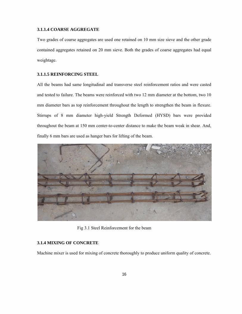
3.1.1.5 REINFORCING STEEL
All the beams had same longitudinal and transverse steel reinforcement ratios and were casted
and tested to failure. The beams were reinforced with two 12 mm diameter at the bottom, two 10
mm diameter bars as top reinforcement throughout the length to strengthen the beam in flexure.
Stirrups of 8 mm diameter high-yield Strength Deformed (HYSD) bars were provided
throughout the beam at 150 mm center-to-center distance to make the beam weak in shear. And,
finally 6 mm bars are used as hanger bars for lifting of the beam.
Fig 3.1 Steel Reinforcement for the beam
3.1.4 MIXING OF CONCRETE
Machine mixer is used for mixing of concrete thoroughly to produce uniform quality of concrete.
17
3.1.5 COMPACTION
Needle vibrator was used for proper Compaction and proper care was taken so as to prevent the
displacement of the internal steel reinforcement cage. And then with the help of a wooden float
and metal trowel, the concrete surface was leveled.
3.1.6 CURING OF CONCRETE
The loss of water due to evaporation can be prevented by curing which is important for the
cement hydration and hardening of concrete. Here curing is done by pouring water on the jute
bags spread over the concrete surface for 28 days.
3.2 STRENGTHENING OF BEAMS
At the time of bonding of glass fiber, the concrete surface was made rough using a coarse sand
paper texture and then the surface was cleaned with an air blower to remove all dirt and debris.
The fabrics were cut according to the size and then the epoxy resin was mixed according to the
instructions of the manufacturer. The mixing was carried out in a plastic mug with 10 parts by
weight of Hardener HY 951 to 100 parts by weight of Araldite LY 556. After mixing it
uniformly, the epoxy resin was applied to the surface where the GFRP is to be applied. Then the
GFRP sheet was placed on top of the coating and the resin was squeezed with the help of the
roller. The entrapped air bubbles in the inter-phase were eliminated. The above process took
place at room temperature. Concrete beams strengthened with GFRP were cured for at least 7
days before testing each of them.
Two beams were strengthened with unbonded glass fibre-reinforced polymer sheets with
end anchorage using steel bolt system. The holes were made during casting and glass FRP sheets
were applied externally on the surface without applying epoxy resin. And, steel bolts were
18
inserted into the holes and using steel plates at both the ends the glass FRP sheets were applied.
Finally, the beams were tested under two point loading.
3.3 EXPERIMENTAL SETUP
The beams were tested in the loading frame of the “Structural Engineering” Laboratory of
National Institute of Technology, Rourkela. The procedure of testing was same for the all the
beams. The two-point loading arrangement was used for the testing of the beams. Two-point
loading was easily provided by the arrangement shown in the figure Fig 3.3
The load was transmitted to the beams through the load cell and a spherical seating. The
beam was installed on rollers seated on steel plates bedded on the test member and cement was
put on the surface to provide a smooth surface. The roller bearings acting on the spreader plates
provided the support to the test member. The specimen was placed over the two steel rollers
bearing and 150 mm from the length of the beam was left from both the ends of the beam. The
1000 mm remaining was bisected into 500 mm each. Two dial gauges are placed just below the
center of the mid span of the beam i.e. just below the load point for recording the deflection of
the beams.
3.4 TESTING OF BEAMS
All the six beams were tested one by one. All of them were tested in the same arrangement.
The deformation readings in the dial gauge for each 10KN of load were recorded throughout
the test. The load at which the first visible crack is developed is recorded as cracking load.
Then the load is applied till the ultimate failure of the beam. The dial gauges placed at mid-
spans measured the deflections at different loads (multiples of 10KN) for all beams with and
without GFRP. The data furnished in this chapter have been interpreted and discussed in the
next chapter to obtain a conclusion.

19
3.4.1 BEAM -1
CONTROL BEAM (CB1)
Fig 3.3 Test Setup for Control beam
The control beam, CB1, failed in the RC shear failure mode. The wide diagonal shear cracks
were observed. The cracks were well extended from mid support to the left centre span. The first
crack of CB1 was obtained at 80KN load and the ultimate failure of the beam occurred at 240KN
load.
Fig 3.4 First Crack on the beam

20
Fig 3.5 Ultimate failure of the beam
3.4.2 BEAM-2
STRENGTHENED BEAM 1 (SB1)
Fig 3.6 Test setup for strengthened beam 1

21
Single layer of glass FRP was applied at the surfaces as shown in the above figure to prevent
shear failure. And it was observed that the beam failed due to debonding of FRP sheet, and
flexural as well as diagonal cracks were also observed. Ultimate load was found to be 288 KN.
Fig 3.7 Failure pattern of SB1
3.4.3 BEAM-3
STRENGTHENED BEAM 2 (SB2)
Fig 3.8 Test setup for SB2

22
Double layer of glass FRP was applied at the same surfaces as shown above in the figure to
prevent shear failure. And it was observed that the beam failed due to debonding of FRP sheet.
This beam showed higher strength compared to CB1 and SB1 and ultimate load was found to be
310KN.
Fig 3.9 Debonding failure of SB2
3.4.4 BEAM-4
STRENGTHENED BEAM 3 (SB3)
Four layers of FRP were applied on the similar surfaces like in SB1 and SB2 to make it strong in
shear. And the result was that this beam also failed due to debonding of FRP sheets and flexural
cracks were found at the central support due to negative bending moment (hogging) at the central
support. The ultimate load of this beam was 340 KN.

23
Fig 3.10 Test Setup for SB3
Fig 3.11 Debonding failure of SB3 accompanied by cracks

24
3.4.5 BEAM-5
STRENGTHENED BEAM 4 (SB4)
In SB4 beam, steel bolt system with unbonded FRP sheet was used to avoid debonding of FRP.
The holes in the beam were made while casting of the beam by using mild steel bars rolled in
plastic sheets as shown in figure
Fig 3.12 Rolling the mild steel bar with plastic sheet
Fig 3.13 Tying of the bars with steel reinforcements

25
Fig 3.14 Test Setup for SB4
Fig 3.15 Development of first crack at 110KN
26
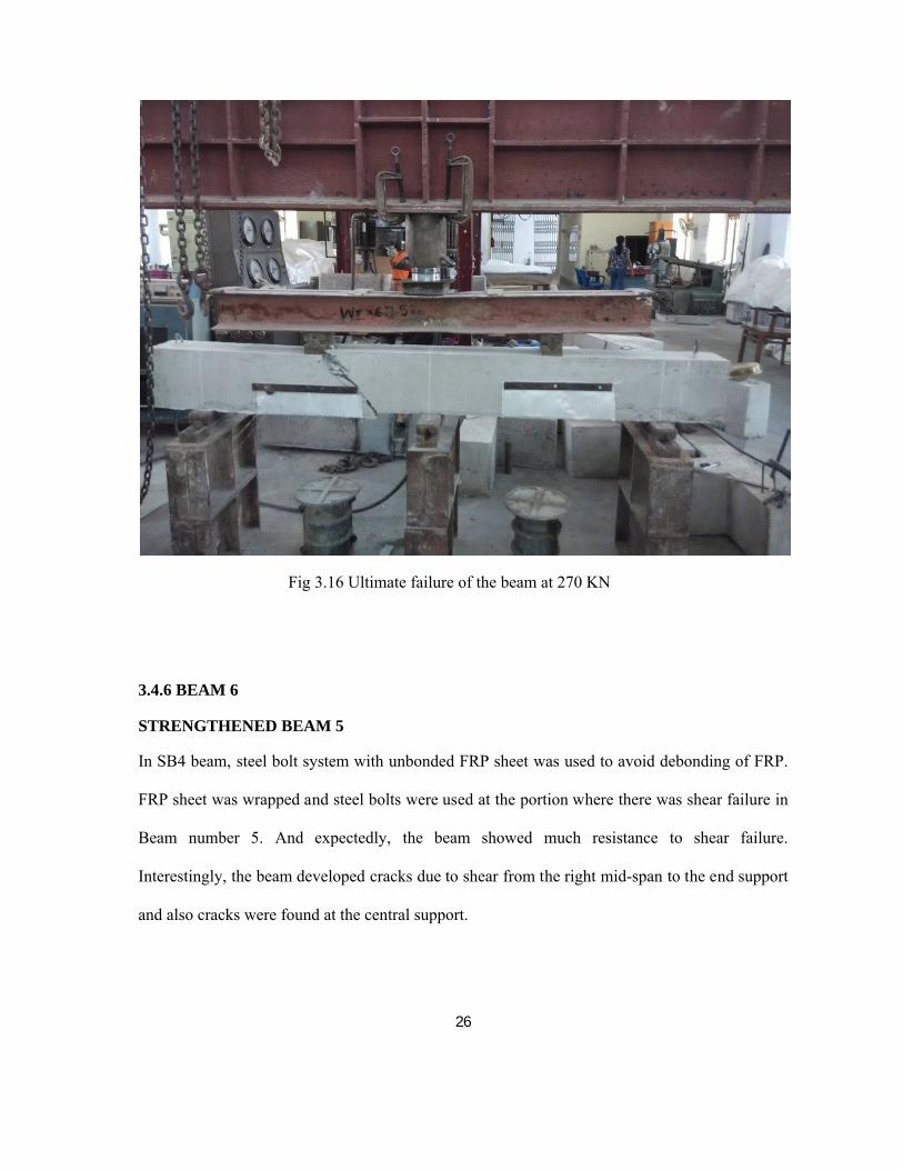
Fig 3.16 Ultimate failure of the beam at 270 KN
3.4.6 BEAM 6
STRENGTHENED BEAM 5
In SB4 beam, steel bolt system with unbonded FRP sheet was used to avoid debonding of FRP.
FRP sheet was wrapped and steel bolts were used at the portion where there was shear failure in
Beam number 5. And expectedly, the beam showed much resistance to shear failure.
Interestingly, the beam developed cracks due to shear from the right mid-span to the end support
and also cracks were found at the central support.

27
Fig 3.17 Test setup for SB 5
Fig 3.18 Diagonal crack at the extreme right support towards load point

28
CHAPTER 4
TEST RESULTS
AND
DISCUSSIONS

29
CHAPTER 4
TEST RESULTS AND DISCUSSIONS
The loadings on the beams were a concentrated load at each mid-span and the experimental
results thus obtained are discussed in terms of the failure mode observed and the load vs
deflection curve. The crack patterns and the mode of failure of each beam are also described in
this chapter. All the beams are tested for their ultimate strengths and it is observed that the
control beam had less load carrying capacity than the strengthened beam. One beam from the
series was tested as un-strengthened control beam and rest beams were strengthened with various
patterns of FRP sheets. The different failure modes of the beams were observed for different
beams.
4.1 EXPERIMENTAL RESULTS
4.1.1 FAILURE MODES
4.1.1.1 CONTROL BEAM
The control beam failed completely in shear. The failure started first at the center span areas and
then propagated towards the central support and finally failed in shear.
4.1.1.2 STRENGTHENED BEAM
Generally, the rupture of FRP sheet was very quick and sudden, and a loud noise was audible
indicating a sudden energy release and thus loss in load-carrying capacity. For all the
strengthened beams, the failure modes are described as below.

30
The following failure modes were examined for all the tested beams:
Shear failure
Debonding failure (with or without concrete cover)
Debonding along with shear cracks at the span
Table 4.1 Experimental Results of the Tested Beams
Designation Of Beams Failure Mode Pu(KN) λ=Pu(strengthened beam)Pu(Control beam)
CB1 Shear failure 240 1
SB1 Debonding failure along with shear cracks
288 1.2
SB2 Debonding failure 310 1.29
SB3 Debonding failure 340 1.42
SB4 Shear failure 270 1.125
SB5 Shear cracks along with cracks at vertical support
318 1.325
The ultimate failure load for all the tested beams are summarized in the above table. The ratio of
load enhancement (λ), which is the ratio of the ultimate load of the strengthened beam to that of
the control beam, is also presented in the table. From the table it is found that, addition of GFRP
layers increased the load-carrying capacity and by introducing the anchoring system, the
enhancement of load capacity can be done.

31
4.2 LOAD DEFLECTION AND LOAD CARRYING CAPACITY
The GFRP strengthened beams and the control beams are tested to find out their ultimate load
carrying capacity. The deflection of each beam under the load point i.e. at the midpoint of each
span position is analyzed. Mid-span deflections of each strengthened beam are compared with
the control beam. It is noted that the behavior of the beams when unbonded or bonded with
GFRP sheets are better than the control beams. The mid-span deflections of the beams are
lower when bonded externally with GFRP sheets. The strengthened beams were found to have
higher stiffness than the control beams. Increasing the numbers of GFRP layers generally
reduced the deflection at mid span and increased the beam stiffness for the same value of load.
The use of GFRP sheet had effect in slowing the growth of cracks.
4.2.1 LOAD-DEFLECTION CURVES FOR ALL BEAMS
The deflections at the mid-spans were recorded at various loads for control as well as the
strengthened beams and the load-deflection curves of the strengthened beams were contrasted
with the control beams and the conclusions were drawn for each beam.
STRENGTHENED BEAMS
Load-displacement curve for SB 1 vs CB
To strengthen SB1, single layer of glass FRP was applied at the surfaces to prevent shear failure.
And it was observed that the deflection values were less than that of the control beam for the
same load value. At lower load value, debonding of FRP without concrete cover occurred and
SB1 finally failed in shear. At the load of 110 KN initial cracks appeared. Later on increasing the
load values, the cracks propagated further and the beam failed with an ultimate load of 288 KN.

32
Fig 4.1 Load-displacement curve for SB 1 vs CB
Load-displacement curve for SB 2 vs CB
SB2 was strengthened with two layers of glass FRP applied at the surfaces similar to SB1 to
prevent shear failure. And from Fig 4.2, it is clear that the deflection values of SB2 are less than
that of the control beam for the same load value. At the load of 130 KN initial hairline cracks
appeared. Later on increasing the load values, the cracks propagated further and the beam failed
with an ultimate load of 310 KN.
0
50
100
150
200
250
300
0 1 2 3 4 5 6 7
Load
(in
KN)
Displacement (in mm)CB SB1
0
50
100
150
200
250
300
0 1 2 3 4 5 6 7
Load
(in
KN)
Displacement (in mm)CB SB2

33
Fig 4.2 Load-displacement curve for SB 2 vs CB
Load-displacement curve for SB 3 vs CB
Similarly, SB3 was strengthened with four layers of glass FRP. And, from the graphs in Fig 4.3
it is clear that the deflection values are much less compared to the control beam for the same load
value. Moreover, the beam failed due to debonding of glass FRP sheets from the concrete cover
and flexural cracks were found at the central support due to negative bending moment (hogging)
at the central support. The ultimate load of SB3 was found out to be as high as 340 KN.
Fig 4.3 Load-displacement curve for SB 3 vs CB
Load-displacement curve for SB 4 vs CB
The technique of strengthening the beams with unbonded glass FRP was used. End anchorage
was provided using steel bolts and plates. In SB4, one layer of glass FRP was U-wrapped just
under the loading points. The ultimate failure of the beam was in shear at 270 KN. And it was
observed that the displacement values were nearer to that of the control beam.
0
50
100
150
200
250
300
0 1 2 3 4 5 6 7
Load
(in
KN)
Displacement (in mm)
CB SB5

34
Fig 4.4 Load-displacement curve for SB 4 vs CB
Load-displacement curve for SB 5 vs CB
SB5 was also strengthened with unbonded glass FRP provided with end anchorages using steel
bolts and plates. In SB5, one layer of glass FRP each was U-wrapped from loading point to
central support .And expectedly, the beam showed much resistance to shear failure. Interestingly,
the beam developed cracks due to shear from the right mid-span to the end support and also
cracks were found at the central support. The ultimate failure occurred at 318 KN.
0
50
100
150
200
250
300
0 1 2 3 4 5 6 7
Load
(in
KN)
Displacement (in mm)
CB SB4

35
Fig 4.5 Load-displacement curve for SB 5 vs CB
Thus, the load carrying-capacity of all the strengthened beams are discussed here, and it is found
that beam SB3 has the maximum load capacity of 340 KN and maximum percentage increase of
load carrying capacity, i.e., 41.67%. Moreover, the ultimate shear capacities of all the
strengthened beams are higher than that of the control beam.
0
50
100
150
200
250
300
0 1 2 3 4 5 6 7
Load
(in
KN)
Displacement (in mm)CB SB5

36
CHAPTER 5
CONCLUSIONS

37
CHAPTER 5
CONCLUSIONS
5.1 CONCLUSIONS
The present experimental study is carried out on the behavior of reinforced concrete
rectangular beams strengthened by GFRP sheets. Six reinforced concrete (RC) beams weak
in shear are casted and tested. All the beams had same longitudinal and transverse steel
reinforcement ratios. The conclusions drawn from the experimental results are as follows:
1. The strengthened beams had higher load-carrying capacity as compared to the control
beam.
2. The initial cracks in the strengthened beams appeared at higher loads compared to the
control beam.
3. The test results show that on strengthening the beams using FRP technique, the shear
capacity can be increased.
4. Strengthened beam SB3, which was strengthened by four layers of FRP showed the
highest ultimate load value of 340 KN and the percentage increase in the load capacity of
SB3 was 41.67 %.
5. On increasing the number of layers of glass FRP, the load carrying capacity of the beams
also increases.
6. Unbonded FRP system with end anchorage using steel bolts and plates is a very new,
time and cost-effective technique.
38
5.2 SCOPE OF THE FUTURE WORK
It promises a great scope for future studies. Following areas are considered for future
research:
a. Experimental study of continuous beams with opening
b. Non-linear analysis of RC continuous beam
c. FEM modeling of unanchored U-wrap
d. FEM modeling of anchored U-wrap
REFERENCES

39
1. Aiello MA, Valente L, and Rizzo A, “Moment redistribution in continuous reinforced
concrete beams strengthened with carbon fiber-reinforced polymer laminates”,
Mechanicsof Composite Materials, vol. 43, pp. 453-466, 2007.
2. Aiello MA, and Ombres L, “Cracking and deformability analysis of reinforced concrete
beams strengthened with externally bonded carbon fiber reinforced polymer sheet”,
ASCEJournal of Materials in Civil Engineering, vol. 16, No. 5, pp.292-399,2004.
3. Arduini M, and Nanni A, “Behaviour of pre-cracked R. C. beams strengthened with
carbon FRP sheets”, ASCE Journal of Composites for Construction, vol. 1, No. 2, pp. 63-
70, 1997.
4. Ashour AF, El-Refaie SA, and Garrity SW, “Flexural strengthening of RC continuous
beams using CFRP laminates”, Cement and Concrete Composites, vol. 26, pp. 765-775,
2003.
5. Ceroni F, “Experimental performances of RC beams strengthened with FRP materials”,
Construction and Building Materials, vol. 24, pp. 1547-1559, 2010.
6. Grace NF, “Strengthening of negative moment region of reinforced concrete beams using
carbon fiber- reinforced polymer strips”, ACI Structural Journal, vol. 98, No. 3, pp. 347-
358, 2001.
7. Grace NF, Sayed GA, and Saleh KR, “Strengthening of continuous beams using fibre
reinforced polymer laminates”, American Concrete Institute, Farmington Hills, Mich, pp.
647-657, 1999.
8. Grace NF, Wael R, and Sayed AA, “Innovative triaxailly braided ductile FRP fabric
forstrengthening structures”, 7th International Symposium on Fiber Reinforce Polymer

40
for Reinforced Concrete Structures, ACI, Kansas City, MO, 2005.
9. Grace NF, Abdel-Sayed G, Soliman AK, and Saleh KR, Strengthening of reinforced
concrete beams using fibre reinforced polymer (FRP) laminates”, ACI Structural Journal,
vol. 96, No. 5, pp. 865-874, 1999.
10. Maghsoudi AA, and Bengar H, “Moment redistribution and ductility of RHSC
continuous beams strengthened with CFRP”, Turkish Journal of Engineering and
EnvironmentalSciences, vol. 33, pp. 45-59, 2009.
11. Obaidat YT, Susanne H, Ola D, Ghazi A, Yahia A, “Retrofitting of reinforced concrete
beams using composite laminates”, Construction and Building Materials, vol. 25, pp.
591-597, 2010.
12. Smith ST, and Teng JG, “Debonding failures in FRP-plated RC Beams with or without U
strip end anchorage” FRP Composites in Civil Engineering, vol. 1, pp. 607–615, 2001.
13. Ross CA, Jerome DM, Tedesco JW, and Hughes ML, “Strengthening of reinforced
concrete beams with externally bonded composite laminates”, ACI Structural Journal,
vol. 96. No. 2, pp. 65-71, 1999.
14. Sebastian WM, “Significance of mid-span de-bonding failure in FRP-plated concrete
beams”, ASCE Journal of Structural Engineering, vol. 127, No. 7, pp.792-798, 2001.
15. Smith ST, and Teng JG, “FRP-strengthened RC beams I: Review of debonding strength
models”, Engineering Structures, vol. 24, No. 4, pp. 385-395, 2002.
16. Teng JG, Smith ST, Yao J, and Chen JF, “Intermediate crack-induced debonding in RC
beams and slabs”, Construcion and Building Materials, vol. 17(6–7), pp. 447–462, 2003.