GFRC – 30 Years of High Fiber Cement Composite ...dualblock.net/grcapplication.pdf · Synopsis:...
19
GFRC – 30 Years of High Fiber Cement Composite Applications Worldwide By Graham T Gilbert Synopsis : Thin, fiber reinforced cementitious products offer a useful balance of properties such as strength, toughness, environmental durability, moisture resistance, dimensional stability, fire resistance, esthetics and ease of handling and installation. For more than 30 years, AR glass fibers have been at the forefront in the development of new applications of such products throughout the World. Glass Fiber Reinforced Concrete [GFRC] is a thin, cement composite based on AR glass fibers with an excellent strength to weight ratio; it is virtually maintenance free being resistant to most environments found in the World. Extensive early laboratory work produced a test method for determining long term strength. The validity of this work has been proven by the large number of buildings clad with GFRC, as well as a vast range of other GFRC products, all of which have given trouble free performance over this 30 year period. This paper explains the fundamental principles behind GFRC and gives examples of some of its uses in the World markets. These applications range from high quality, architectural wall panels and decorative elements through to modular buildings down to low cost channel sections and utility components. New developments and techniques will also be touched upon. Keywords: AR glass fibers; AR meshes; AR mats; engineering properties; manufacturing methods; durability. Wall panels; decorative elements; modular buildings; thin cementitious products; fiber cement; Fiber reinforcement; 1
Transcript of GFRC – 30 Years of High Fiber Cement Composite ...dualblock.net/grcapplication.pdf · Synopsis:...

GFRC – 30 Years of High Fiber Cement Composite Applications Worldwide
By Graham T Gilbert Synopsis: Thin, fiber reinforced cementitious products offer a useful balance of properties such as strength, toughness, environmental durability, moisture resistance, dimensional stability, fire resistance, esthetics and ease of handling and installation. For more than 30 years, AR glass fibers have been at the forefront in the development of new applications of such products throughout the World. Glass Fiber Reinforced Concrete [GFRC] is a thin, cement composite based on AR glass fibers with an excellent strength to weight ratio; it is virtually maintenance free being resistant to most environments found in the World. Extensive early laboratory work produced a test method for determining long term strength. The validity of this work has been proven by the large number of buildings clad with GFRC, as well as a vast range of other GFRC products, all of which have given trouble free performance over this 30 year period. This paper explains the fundamental principles behind GFRC and gives examples of some of its uses in the World markets. These applications range from high quality, architectural wall panels and decorative elements through to modular buildings down to low cost channel sections and utility components. New developments and techniques will also be touched upon. Keywords: AR glass fibers; AR meshes; AR mats; engineering properties; manufacturing methods; durability. Wall panels; decorative elements; modular buildings; thin cementitious products; fiber cement; Fiber reinforcement;
1

Graham T Gilbert, CChem. MRSC is a Chartered Chemist and a Member of the Royal Society of Chemistry. He is currently with Vetrotex Cem-FIL, a subsidiary company of the Saint-Gobain Group, one of the World’s leading suppliers of building materials. Based in the UK, he has worked on the use of AR Glass fibers as a fibrous reinforcement for cement based composites and concrete for more than 30 years. During this period, he has traveled extensively encompassing all the major European countries as well as the Middle East and North America providing techno-commercial support to both new and existing manufacturers. He is also a member of the American Concrete Institute, The Precast/Prestressed Institute and the International Glassfibre Reinforced Concrete Association. 1.0 INTRODUCTION Cement based materials have inherent defects such as flaws in the matrix due to shrinkage and debonding at interfaces. AR glass fibers in this brittle cementitious materials help to enhance the composite toughness and tensile strength by synergistically interacting with the micro cracks that develop when the composite is loaded. The AR glass fibers restrain crack opening and crack growth by effectively bridging across the micro cracks. The most common form of glass fibers, E-glass, is used as a reinforcing material in resin composites referred to as FRP. However, when E-glass fibers are exposed to portland cement based mixtures, such as mortars or regular concrete, the alkaline nature of the cementitious mixtures rapidly deteriorates the glass fiber. Because of this, AR glass fibers were developed by intrinsically modifying the chemical composition of the glass fibers such that they are inherently more chemically resistant to the alkaline nature of cementitious matrix. The actual dose rate used will determine the final composite properties with 0.6kg/cu.m. [1lb/cu.yd] being used for plastic shrinkage cracking of regular concrete. However, thin section [1/2”] GFR Concrete will use much higher dose rates ranging from 2-5% of total weight being the normal range. Recently, dose rates as high as 15-18% of continuous filament have been used for the newly developed filament wound poles. The exceptional high tensile strength of AR glass fibers imparts tensile properties to the resultant composite as well as improving its toughness and impact strength. Because GFRC has both good tensile and compressive strength as well as being lightweight with good fire properties and low maintenance, it has been
2

used throughout the World in a wide range of applications and these will be highlighted later in this paper. 2.0 AR GLASS FIBERS 2.1 General Data and Fiber Types In order to make glass fibers resistant to the lime generated during the setting of Portland cement, zirconium is added to the glass mixture composition prior to melting and fiberising the raw materials. The added zirconium becomes part of the glass fiber molecular structure in the manufacturing process i.e. it is not just a protective coating. The minimum zirconium content in the composition for good durability is about 16% by weight. The glass fibers with this zirconium modification are usually referred to as alkali-resistant glass fibers or AR glass fibers. AR glass fibers are chemically stable resisting both alkali and acid conditions. Chemical composition of the AR glass fibers is shown in Table 1 and the physical and mechanical properties in Table 2.
Table 1-Chemical composition of AR-glass fibers, percent by weight (PCI MNL-128-01)
Component AR-glass SiO2 61.0-62.0 Na2O 14.8-15.0 CaO - MgO - K2O 0.0-2.0
Al2O3 0.0-0.8 Fe2O3 - B2O3 - ZrO2 16.7-20.0 TiO2 0.0-0.1 Li2O 0.0-1.0
Table 2-Properties AR-glass fibers (PCI MNL-128-01) Property AR-Glass Specific Gravity 2.70-2.74 Tensile Strength, MPa [psi] 1700 [2.5 x 10⁵] Modulus of Elasticity, GPa [psi] 72 [10.4 x 10⁶] Strain at Break, % 2.0
3

AR.glass fibers for use in concrete are available in three basic forms - discrete chopped strands [CS], continuous rovings and meshes. 2.1.1 AR Glass Fiber Discrete Chopped Strands-- are used primarily in premix glass fiber reinforced concrete [high dose rate] and in crack control of concrete [low dose rate]. Typically, AR glass fiber CS are available in two types, integral and water dispersible. Glass fiber CS are made up of bundles of individual filaments with the typical diameter of these filaments being 12-20 microns. 2.1.2 Integral Chopped Strands-- are designed to stay as bundles of filaments through mixing and placing, with as little breakdown of the bundle as possible [Fig 1A]. Integral strand bundles can contain as many 400 and as few as 50 filaments. The number of filaments per bundle is usually referred as strand geometry. The diameter of the individual filaments, the number of filaments that are bundled together, and the integrity of the bundle are the key factors that determine performance characteristics of the strand. The typical length of discrete AR glass fiber strands used in thin-reinforced products ranges between 6 [1/4”] to 40 [1 ¾”] mm. The strand geometry, strand length, and glass fiber content all contribute to the processing characteristics of the composite and its final properties. 2.1.3 Water dispersible Chopped Strands-- are designed to disperse quickly into individual strands on contact with water or an aqueous cementitious mixture. These fibers are used in composites where a fine dispersion of individual monofilaments is desired rather than intact fiber bundles. In particular, water dispersible AR glass fibers are commonly used to reduce cracking in concrete, mortars and stucco application and in manufacturing processes that involve cementitious slurries with initial high water content such as modified Hatschek process or for calcium and sodium silicate applications frequently using the filter-press processes. Typical length of water dispersible AR glass fiber strands used in thin-reinforced cement products ranges between 6 [1/4”] to 25 [1”] mm. 2.1.4 Continuous AR Glass Fibers-- are available in the form of roving [Fig. 1B]. A roving is an assemblage of several continuous AR glass fiber monofilaments. The manner in which the monofilaments are assembled varies and differentiates one roving type from another. Fundamentally, the construction of an AR fiber roving is as follows: Several continuous alkali-resistant glass fiber monofilaments are
gathered together to form a continuous strand. The typical diameter of the individual alkali-resistant glass fiber monofilaments ranges between 10 to 20 microns. Typically, the number of monofilaments that are gathered together to form a continuous strand ranges between 50 to 400.
4

Several continuous strands as explained above are assembled together to form a continuous roving. Typically, the number of continuous strands that are assembled to form a continuous roving ranges between 20 to100.
2.1.6 Glass Fiber Meshes and Mats-- are woven or dipped, non-woven products from assembled glass fiber rovings or strands whilst mats are chopped fibers bonded together with a polymeric coating. Traditionally they were woven products of heavily coated E-glass fiber yarn used mainly in the production of cement boards (Venta et al. 1995, 1997, 1998). As an alternative, an alkali-resistant (AR) glass fiber mesh can be used to reduce the need for the coating. The AR mesh has recently been used in a new system for seismic improvement of masonry walls. 3.0 PRODUCTION METHODS 3.1 Simultaneous Spray Process In the simultaneous spray process, continuous AR glass fibers are chopped through a gun and air-sprayed simultaneously with the cement slurry onto a mold surface, [Figure 2]. To spray the entire mold area, both the fiber and cement slurry spray guns are moved to follow the contours of the mold. Successive 4-6mm [≈1/4”] layers are sprayed and roller compacted to form a typical 12-15 mm thick (≈½” ] panel. The compaction removes air, helps bond and ensure a good quality finish. The simultaneous spray process can be manual or automated. Spray process allows tremendous flexibility in manufacturing complex architectural shapes as well as producing a high strength product. Consequently, architects around the globe commonly design and specify architectural shapes manufactured using the spray process 3.2 Premix Process The premix process consists of first mixing together the other ingredients (cement, sand, admixtures, water, etc.) in a standard or specialized mixer to give a low viscosity mortar. The AR chopped strands are added to this mortar and cast to from a thin product of desired shape in a mold. The casting process may be similar to concrete casting or hand packing [lower strengths] or it may not involve spraying of fiber-cement slurry as a method to fill the mold and/or vibration to achieve satisfactory slurry compaction in the mold. In the premix process, the maximum amount of
5

fibers that can be incorporated in the mixture is dependent upon the length and diameter of the fibers used. Additives such as polymers, pozzolans e.g. metakaolin, and/or flow aids such as water reducing agents are generally used to facilitate the mixing operation. The premix process typically yields a three-dimensional random orientation of fibers in the mixture. Consequently, premix products are not as strong as simultaneous sprayed ones but the process has the advantage of ease of production and a lower level of skill required to produce the end product. 3.3 Filament Winding Process Filament winding process was developed for FRP composites but has recently been used to produce GFRC poles. The fiber roving strand passes over several round steel bars placed below the level of a specially modified mortar mix before being wound onto a mandrel. Various continuous fiber cement based composites consisting of unidirectional lamina, cross ply and angle ply laminates can be manufactured with a typical AR glass content of Vf 13%. Mechanical properties of wound tube test specimens gave tensile strengths higher than 300 MPa [50,000psi] and flexural strengths as high as 200 MPa [30, 000psi] The filament winding method has been refined commercially in the US for the production of a range of poles and inductively transparent, high temperature ladles with glass fiber volume fraction ranging from Vf 10 to 25%. [Ref US Patents 5039345 (Mott 1991) and 5880404 (Stanley and Mott 1999). Figure 3 shows a pole being wound onto a mandrel with AR glass fibers 3.4 Filter-press Process In the filter-press process, first a wet fibrous mix is produced with an excess of water. Then this mix is charged into a mold, which has a perforated plate at the base. A filter material is laid on top of the mold base. The mix is then pressed by a top plate, which squeezes out the excess water through the base of the mold and through a small gap between the top plate and the sides of the mold. The compressed board or tile is then removed from the mold and stacked for curing. Depending on the shape, the product can be demolded immediately whilst in the unhardened state. It is also possible to use rapid setting cements to accomplish instant demolding. The filter-press process is well suited for mass production of products having simple or complex shapes.
6

4.0 GLASS FIBER REINFORCED PRODUCTS PROPERTIES
The physical and mechanical properties of glass fiber reinforced concrete are discussed more fully in ACI 544.1R-96. The following summarizes these properties. The mechanical properties of GFRC composites depend upon the fiber content, water/cement ratio, density, sand content, fiber orientation, fiber length, and polymer content if used. Typical properties for traditional spray up GFRC containing 5% by weight of glass fibers are shown in Table 3 (PCI MNL-128-01). As shown in this table, GFRC composites have significant load and strain capacity. Whilst some of these properties reduce a little with time for standard GFRC their real time performance is well documented and all accepted design procedures allow for it in establishing design values. PCI publication MNL-128-01, ‘Recommended Practice for Glass Fiber Reinforced Concrete Panels’ details the most widely accepted design procedure in the industry. If reduction in mechanical performance of composites is of concern, GFRC composition can be modified in several ways to prevent this from occurring. The formation of calcium hydroxide within the fiber strands has been held to be largely responsible for the change in properties with time (Bentur 1985). The measures that are used to arrest the change in properties generally attempt to prevent the formation of calcium hydroxide. The glass fiber manufacturers have made available alkali-resistant glass fibers with special coatings that reduce the affinity of the fibers for calcium hydroxide (Hayashi, Sato, and Fuji 1985). Most other methods to improve durability of GFRC rely on either the use of pozzolanic admixtures such as silica fume, metakaolin or fly ash, (Marikunte, Aldea, and Shah 1997; Soukatchoff 1999; Soukatchoff and Ridd 1991; Purnell et al. 1991) or use of special cements such as calcium sulphoaluminate cements that do not produce calcium hydroxide as a hydration product (Molloy, Jones, and Harmon 1993; Molloy and Jones 1993). Acrylic thermoplastic co-polymers have also been reported to reduce the extent of reduction in mechanical performance with time (Ball and Wackers 2001). Acrylic thermoplastic co-polymers are usually used in GFRC products because they improve the curing of the GFRC In addition to traditional spray up GFRC, premix glass fiber reinforced concrete is growing in use for certain products. Typical properties for premix GFRC are shown in Table 4 (PCI MNL-128-01). Generally premix GFRC has a lower fiber content, uses shorter fibers, and has significantly greater three dimensional fiber orientation than the largely two-dimensional orientation obtained with spray up GFRC, which all contribute to it having lower mechanical performance than the spray up GFRC.
7

Table 3: Typical range of traditional sprayed GFRC propertiesa (PCI MNL-128-01) Property 28-day Agedb Dry Density t/cu.m. [pcf] 1.9-2.1 [120 to 140] 1.9-2.1 [120 to 140] Compressive MPa [psi] 50-82 [7-12,000] 70-82 [10-> 12,000] Flexural: MPa [psi] Yield (FY) Ultimate strength (FU) Modulus of elasticity GPa [psi]
6-10 [900 ->1,500] 14-24 [2000 to 3,500] 7-21 [1->3.0x10⁶]
7-11 [1,000 to 1,600] 9-17 [1300 to 2,500] 18-28 [2.5-> 4.0x10⁶]
Direct Tension: MPa [psi] Yield (TY) Ultimate strength (TU) Strain to failure %
5-7 [700 to 1,000] 7-11 [1,000 to 1,600] 0.6 to 1.2
5-7 [700 to 1,000] 5-8 [725 to 1,100] 0.03 to 0.08
Shear: MPA [psi] Interlaminar In-plane
3-6 [400 to 800] 7-11 [1,000 to 1,600]
3-6 [400 to 800] 5-8 [725 to 1,100]
Coef. of thermal expansion /0C (in./in./oF)
10-20 x 10-6 [≈12x10-6]
10-20 x 10-6 [≈12x10-6 ]
Thermal conductivity. W/m0C (Btu/in./hr/ft2/ oF)
0.5 to 1.0 [3.5 to 7.0]
0.5 to 1.0 [3.5 to 7.0 ]
Note: aThese are typical values and are not to be used for design or control purposes. Each manufacturer must test production composites to establish properties for design. The values achieved in practice will be dependent on mix design, quality control of materials, fabrication process and curing. Cement/sand ratio in the above composites ranges between 1:1 to 3:1. bDeveloped from accelerated testing programs on GFRC specimens immersed in 50 to 80oC (122 and 175oF) water. On the basis of comparisons between behavior in real weather and accelerated tests, predictions can be made of properties for 50+ years in different climates.
8

Table 4: Typical range of premix GFRC propertiesa (PCI MNL-128-01) Property 28 day Metric Equivalent Density (dry) 1.8-2.0 T/cu.m 110 to 130 pcf Compressive Strength 40-60 MPa 6,000 to 9,000 psi Flexural: Yield (FY) Ultimate strength (FU) Modulus of elasticity
50-80MPa 10-14MPa 7-20GPa
700 to 1,200 psi 1,450 to 2,000 psi 1.0x10⁶ to 2.9x10⁶psi
Direct Tension: Yield (TY) Ultimate strength (TU) Strain to failure
4-6Mpa 4-7MPa 0.1-2%
600 to 900 psi 600 to 1,000 psi 0.1 to 0.2 percent
Shear: In-plane 4-7MPa 600 to 1000 psi Coefficient of thermal expansion
10-20 x 10-6 /0C Approx. 12x10-6 (in./in./oF)
Thermal conductivity 0.5 to 1.0 W/m0C
3.5 to 7.0 (Btu/in./hr/ft2/ oF)
Note: aThese are typical values and are not to be used for design or control purposes. Each manufacturer must test production composites to establish properties for design. The values achieved in practice will be dependent on mix design, quality control of materials, fabrication process and curing.
5.0 APPLICATIONS OF GFRC WORLDWIDE
5.1 Cladding 5.1.1 Modular Buildings, -- Single- or two-storey, have been constructed with AR glass fiber reinforced cementitious sandwich panels integrated into a lightweight steel structural frame during erection. Sandwich construction of the panel involves two 8 mm thick AR fiber reinforced concrete skins attached onto both sides of a 155 mm thick core of lightweight concrete. This building system has been independently tested for load capacity, sound insulation, thermal conductivity, and fire resistance. Figure 4 & 5 shows an example of such a system. Much earlier, in the late 1970’s, GFRC panels were used on exterior wall of prefabricated timber frame houses constructed to meet the shortage of dwellings in Scotland. The panels were typically 10 mm thick and had an
9

aggregate finish surface. Simple cast-in washers for face fixing the panels were incorporated at 50 mm on center. Wind pull off tests conducted on the wall systems yielded results in excess of those needed for the 200 km/hour (125 mph) gusts found in that region. These houses were independently inspected by the GRCA (Glass Reinforced Concrete Association, UK) after 20 years and were found to be in good and serviceable condition.
Figure 6 shows these dwellings after 20 years exposure in the Highlands of Scotland 5.1.2 GFRC Architectural Façade Panels -- can be manufactured as wall and window units, spandrel, soffit and fascia panels, mansard roof elements as well as mullions, cornices and column covers. Figure 7 shows a photograph of the Cervantes Convention Center situated in St. Louis in which 1670 square meters of the building exterior was clad with GFRC architectural façade panels. The panel size varied but the average was approx. 2.4 m x 6.0 m. The panel skin consisted of 12.5 mm thick GFRC plus a 6 mm thick facing mix attached to a structural steel frame, which in turn was attached to the building. In several panels, two finishes were combined on the same panel. Brick red finish on the panels was achieved with the use of white cements, sands and pigments. The intricate architectural details on these panels were created by forming the panels over rubber liner molds. Some panels also had limestone finish. This was achieved with the use crushed stone, pigment and sandblasting. There are innumerable examples of high quality, architectural panels on buildings completed for over 30 years around the World. Fig 8 shows the recently completed Nile City Project in Cairo and Fig. 9 the San Francisco Towers complex in California where 155 000 GFRC panels were used. 5.1.3 GFRC Decorative Elements --are capable of closely imitating natural materials, which tend to be expensive and in short supply. Thin complex shapes with excellent surface finish and surface details can be easily formed using AR glass fiber reinforced cementitious materials. Molds to form these shapes are frequently taken from deteriorated original carvings. GFRC architectural elements are relatively light in weight and require low maintenance. These attributes make GFRC architectural elements a sensible choice for both new and refurbished buildings. Figure 10a & b and Fig.11 show some applications. 5.2 Road and rail Sound Walls
Throughout the world, new highways and mass transit rail systems compete for space in already developed urban areas. The result is that major traffic routes are found closer to commercial and residential areas
10

and it becomes necessary to suppress noise pollution to the surroundings. GFRC noise barriers are being increasingly used since they are light in weight and offer simplicity and speed of erection without requiring the use of heavy lifting machinery. This gives reduced disruption to traffic and greatly reduced loads on any elevated structures allowing for the same material to be used throughout. The moldability of GFRC allows for aesthetically pleasing designs which are more attractive and acceptable to both residents and travelers as well as to bridge engineers and architects alike. In addition, GFRC has excellent resistance to salt attack, freeze-thaw and rotting thus reducing maintenance.
Figure 12 shows a GFRC reflective sound wall in Spain and Fig 13 a different design, absorbing, in South East Asia 5.3. Ducts and Channels 5.3.1 Drainage Channels --- for drainage and transporting liquids represent another application for GFRC. Fig 14 shows a commercially available high volume, rain-water drainage channel used in parking lots, road and highway applications. These channels are designed for optimum flow capacity and are available in different cross-sectional sizes with lengths ranging up to 2 meters (6.6 feet). Further, these channels are lightweight, easy to install in long sections with reduced excavation, maintenance free, and require fewer silt traps or manholes due to their superior hydraulic performance. The channels are produced by vibration casting an AR fibers mix into a two-part mold. 5.4.2 Cable and Pipe Ducts and Conduits --in GFRC are used in Europe, Japan and the USA. Figure 15 shows GFRC pipe trench liner in USA. 5.5 Tunnel and sewer Linings 5.5.1 Tunnel Liners --GFRC has been widely used for tunnel lining applications and Figure 16 & 17 shows Heathrow Express railway station at Heathrow Airport, London, UK. The panels used in this application are nominally 12 to 18 mm (½” to ¾”) thick and are made from a cementitious mixture reinforced with alkali-resistant glass. Lining within the stations consisted of 9000 acid-etched and sand-blasted panels of size 1.8 m (5.9’) wide, 0.90 m (2.95’) wide and 0.70 m (2.3’) deep. A 50 mm (2”) deep recess in each panel allowed enamelled glass advertising panels to be secured within.
11

5.5.2 Sewer Linings- -Figure 18. shows a photograph of thin reinforced cementitious sewer lining application. GFRC sections are very versatile and cost effective, and thereby offer several significant advantages over FRP in sewer applications. They are stiffer and bond well with the grout lining, essentially becoming part of the sewer structure. Consequently, they are more resistant to the damaging influences of water pressure or ground movement. 5.5.3 Canal Bank Protection Linings-- in GFRC is demonstrated in Figure 19. Such linings are used to prevent erosion of the canal banks caused by different sources such as hydraulic discharge and incidental contact with passing boats. The panels are typically 6 to 9 mm thick, with ribs on rear face for strength and stiffness. The typical size of the panels is about 2 m x 1.36 m (6.5’ x 4.5’). 5.6 Pipes and Poles Filament wound GFRC poles have recently been developed in North America. Figure 20. shows a pole manufactured using continuous alkali-resistant glass fibers. These poles can have a fiber volume fraction as high as 25%. In terms of their mechanical behavior, these products are exceptionally strong in tension (notched tensile strength of about 90 MPa), compression (compressive strength of about 175 MPa) and flexure (bending strengths of about 150 MPa). Using the filament winding process, the pole products can be easily manufactured in lengths of up to 15 meters (50 feet). Potential applications of the pole products include induction and wireless transmission-invisible poles and permanent formwork for seismic and marine columns. 5.7 Bridge Parapets Fig. 21 shows GFRC panels used on the BTS Skytrain, Thailand’s first mass transit system. The project extended about 23 km (14 miles) through the heart of the Bangkok and was entirely elevated. The parapets shown in this figure are typically 1.1 m high, 2.7 m long, and nominally 15 mm thick with ribbed top and bottom using expanded polystyrene void-formers. The ribbing provides the panels with additional strength and rigidity to resist the high wind loads caused by the passing trains. The parapet panels shown in this figure are reinforced with discrete, alkali-resistant glass fibers.
12

5.8 Landscaping Products Glass fiber reinforced concrete is used widely for simulated rock installations in zoos, hotel and office lobbies, swimming pools, climbing walls, golf courses, and theme parks. Thin cementitious panels are usually factory prefabricated using the spray up process or sprayed premix. The molds are usually made of rubber that has been cast off an actual rock face. The cast panels are then assembled on the job site. The panels can be integrally colored or can be colored on the job site using acrylic stains.
6.0 SUMMARY Glass fiber reinforced concrete, GFRC is an ultra-thin form of concrete with the AR glass fibers complimenting the high compressive strength of the cementitous matrix with the high tensile strength of the glass fiber. The resulting composite, usually only ½ -1” thick, offers a unique balance of properties such as strength, toughness, dimensional stability, environmental durability, moisture resistance, freeze thaw resistance, fire resistance, esthetics, and ease of handling and installation. Because of this blend of attractive properties, GFRC has found a wide range of uses in more than 40 countries spanning a period of more than 30 years. The fibers are easy to incorporate using a variety of production methods to suit the end need. Applications range from the highly visible large architectural panels on low and high rise buildings to decorative elements to more mundane uses such as ducts and channels and tunnel linings
13

Fig 1A AR Glass Fiber Chopped Strands
Fig 2 Simultaneous Spraying of GFRC
Fig 1B AR Glass Fiber Continuous Strand Roving
Fig 3 Filament Winding of a pole with AR Glass Fibers
Fig 1C AR Glass Fiber Mesh
14

Fig4 GFRC Insulated Wall Panels for Modular Housing in Dubai
Fig5 Floor Plan of Modular Construction House
Fig 6 Timber Frame Houses with Single Skin GFRC Panels. Built 1976 UK
15

Fig 7 1670 sq.m of GFRC panels on the Cervantes Convention Centre, St Louis. 2 finishes – Ornate/pigmented and stone simulation
Fig 8 Nile City project, Egypt.
2 x twin Towers
16
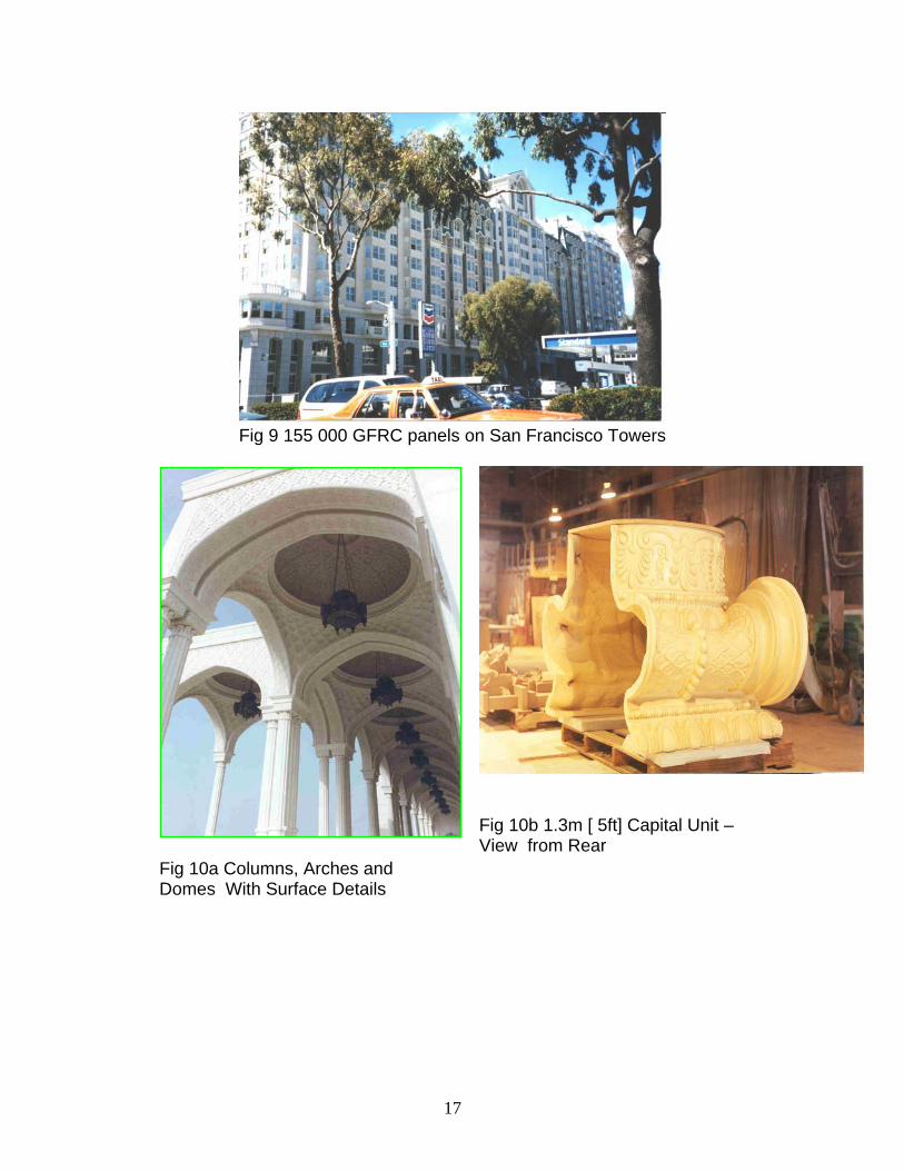
Fig 9 155 000 GFRC panels on San Francisco Towers
Fig 10a Columns, Arches and Domes With Surface Details
Fig 10b 1.3m [ 5ft] Capital Unit –View from Rear
17

Fig 11 Terra Cotta Replacement on Shepard Hall, New York
- 72000 units with more than 4000 shapes inc.scupltures
Fig 12 Reflecting Noise Barrier,
Fig 13 Absorbing Barrier S.E Asia
<-Fig 14 Engineered, Optimum Flow Drainage Channels, UK
Fig 15 Pipe Trench Liners, USA
18

Fig 16 &17 Heathrow, London
Fig 18 Sewer Re-lining
Fig 19 River Bank Protection
Fig 20 GFRC Pole 7.5m [25’]
Fig 21 Bridge Parapets, Thailand
19