
gfk1832
51
GE Fanuc Automation Operator Interface Products Shallowback Display Station 2000 User's Guide GFK-1832 July 2000
description
gfk1832
Transcript of gfk1832

GE Fanuc Automation
Operator Interface Products
Shallowback Display Station 2000
User's Guide
GFK-1832 July 2000

GFL-002
Warnings, Cautions, and Notesas Used in this Publication
WarningWarning notices are used in this publication to emphasize that hazardous voltages,currents, temperatures, or other conditions that could cause personal injury exist in thisequipment or may be associated with its use.
In situations where inattention could cause either personal injury or damage toequipment, a Warning notice is used.
CautionCaution notices are used where equipment might be damaged if care is not taken.
NoteNotes merely call attention to information that is especially significant to understanding andoperating the equipment.
This document is based on information available at the time of its publication. While effortshave been made to be accurate, the information contained herein does not purport to cover alldetails or variations in hardware or software, nor to provide for every possible contingency inconnection with installation, operation, or maintenance. Features may be described hereinwhich are not present in all hardware and software systems. GE Fanuc Automation assumes noobligation of notice to holders of this document with respect to changes subsequently made.
GE Fanuc Automation makes no representation or warranty, expressed, implied, or statutorywith respect to, and assumes no responsibility for the accuracy, completeness, sufficiency, orusefulness of the information contained herein. No warranties of merchantability or fitness forpurpose shall apply.
The following are trademarks of GE Fanuc Automation North America, Inc.
Alarm Master Genius PROMACRO Series SixCIMPLICITY Helpmate PowerMotion Series ThreeCIMPLICITY 90–ADS Logicmaster PowerTRAC VersaMaxCIMSTAR Modelmaster Series 90 VersaProField Control Motion Mate Series Five VuMasterGEnet ProLoop Series One Workmaster
©Copyright 2000 GE Fanuc Automation North America, Inc.All Rights Reserved.

Preface
GFK-1832 iii
Content of This Manual
This manual describes the features and operation of the following Shallowback Display Station2000 series products:
Catalog Number Features
IC752WTG502 15” LCD with PC/104 and Windows NT, 233 MHz MMX, 64 Mbytes RAM
IC752WTG552 15” LCD, PC/104, Windows NT with upgraded processor and RAM
IC752WTH802 18” LCD with PC/104 and Windows NT, 233 MHz MMX, 64 Mbytes RAM
IC752WTH852 18” LCD, PC/104, Windows NT with upgraded processor and RAM
Related Publications
GFK-1189 CIMPLICITY® HMI for Windows NT™ and Windows® 95 Important ProductInformation
GFK-1180 CIMPLICITY® HMI for Windows NT™/CIMPLICITY HMI forWindows® 95/CIMPLICITY Server for Windows NT™ Base System User Manual
GFK-1181 CIMPLICITY® HMI for Windows NT™/CIMPLICITY HMI forWindows® 95/CIMPLICITY Server for Windows NT™ Device CommunicationsManual
GFK-1396 CIMPLICITY® HMI for Windows NT and Windows 95 CimEdit OperationManual


Contents
GFK-1832 v
Chapter 1 Shallowback Display Station 2000 Features..................................................... 1-1
Features Summary ....................................................................................................1-2Standard Features................................................................................................1-2Optional Features................................................................................................1-3
System I/O ...............................................................................................................1-3Standard I/O .......................................................................................................1-3
Network Interface .....................................................................................................1-3Application Software.................................................................................................1-3PC/104 Card Expansion.............................................................................................1-3
Chapter 2 Powerup and Software Installation................................................................... 2-1
Initial Startup............................................................................................................2-1Powering Up the Shallowback Display Station 2000 .............................................2-2Setting Up Windows NT Systems ........................................................................2-2Configuring the Display Station to Run on a Microsoft Network ............................2-3
Login Recommendation.................................................................................................2-4Registering Your CIMPLICITY Software...................................................................2-4Installing Application Software..................................................................................2-5
Directory Structure..............................................................................................2-5Windows NT Systems....................................................................................................2-5
Reloading NT on the Hard Disk From CD ............................................................2-5Touch Screen Driver for Windows .......................................................................2-6
Image Recovery........................................................................................................2-7Instructions for Image Recovery ..........................................................................2-7
Shutting Down the Computer.....................................................................................2-7
Chapter 3 Hardware Installation......................................................................................... 3-1
Mounting Guidelines.................................................................................................3-1Mounting Procedure..................................................................................................3-2Installing Expansion Cards and/or RAM.....................................................................3-3
Installing a PC/104 Card......................................................................................3-3Changing the Air Filter Element.................................................................................3-5
Chapter 4 Connectors ........................................................................................................... 4-1
Power Input..............................................................................................................4-2Serial Communication Cables ....................................................................................4-3Printer Port LPT1 .....................................................................................................4-4
Chapter 5 System Operation................................................................................................ 5-1
System Peripherals ....................................................................................................5-2Hard Disk Drive..................................................................................................5-2Floppy Disk Drive...............................................................................................5-2

Contents
vi Shallowback Display Station 2000 User's Guide–July 2000 GFK-1832
CD-ROM Drive..................................................................................................5-2Graphics System.......................................................................................................5-3
Display Types.....................................................................................................5-3Graphics Controller.............................................................................................5-3
Operator Interfaces....................................................................................................5-4External Keyboard and Mouse .............................................................................5-4Touch Screen......................................................................................................5-4
Touch Screen Driver for Windows................................................................................5-5Control Functions ...............................................................................................5-5
Shallowback Display Station 2000 15-inch and 18-Inch Models ...............................5-5Control/Status Panel .......................................................................................................5-6
CIMPLICITY HMI Software.....................................................................................5-8Communications .......................................................................................................5-9
Chapter 6 BIOS Settings....................................................................................................... 6-1
Chapter 7 Diagnostics and Troubleshooting....................................................................... 7-1
Self-Test Diagnostics ................................................................................................7-1System Test and Initialization ..............................................................................7-1System Configuration Verification .......................................................................7-1
Troubleshooting........................................................................................................7-2Powerup.............................................................................................................7-2Display...............................................................................................................7-3Memory .............................................................................................................7-3Touch Screen......................................................................................................7-4External PS/2 Mouse...........................................................................................7-4Keyboard............................................................................................................7-5Communications .................................................................................................7-5
PLC/CPU Connection ....................................................................................................7-5MODBUS RTU Communications.................................................................................7-6Network Communications .............................................................................................7-6
Printing..............................................................................................................7-7Corrective Actions ....................................................................................................7-8
CMOS Checksum Error.......................................................................................7-8

Contents
GFK-1832 Contents vii
Appendix A Technical Data.................................................................................................... A-1
Mechanical Specifications ........................................................................................ A-1Front Assembly ................................................................................................. A-1Touch Screen..................................................................................................... A-1Main Chassis ..................................................................................................... A-1Rear Cover ........................................................................................................ A-2Panel Mounting System...................................................................................... A-2
Functional Specifications.......................................................................................... A-2Environmental Specifications.................................................................................... A-4Filter Pad Specifications ........................................................................................... A-4

GFK-1832 1-1
Shallowback Display Station 2000 Features
The Shallowback Display Station 2000 is a highperformance workstation incorporating the latestIndustrial PC architecture. The Shallowback DisplayStation 2000 is designed primarily as a hardwareplatform for Supervisory Control and Data Acquisition(SCADA) software packages running under WindowsNT® operating systems. The Shallowback DisplayStation 2000 is available with a 15 inch or 18 inchTFT Active Matrix display and resistive touch screen.
Each model in the Shallowback Display Station 2000range is a fully self contained PC-compatiblecomputer with built-in flat screen display and resistivetouch screen, housed in an industrial, IP65 rated frontpanel mounted unit. The 18’ version weighs only 32 lbs.(14.51 kg); the 15” weighs 24.35 lbs. (11.04 kg). The unit ishoused in a rugged metal case to protect the system againstdust, water, and damage.
Shallowback Display Station 2000 models are available withautoranging power input unit for 110 or 220 VAC.
The unit is supplied completely assembled and requires only mounting and connecting. The use ofspecial clips to secure the unit to the panel eliminates the need for mounting holes and requiresonly one cut-out to mount the unit.
Note
Before powering up your system for the first time, you should refer to Chapter 2for procedures that contain information you need to set up the operating systemand network communications.
1Chapter

1-2 Shallowback Display Station 2000 User's Guide – July 2000 GFK-1832
1
Features SummaryWhen you purchase a Shallowback CIMPLICITY Display Station system, you receive:
• CIMPLICITY Shallowback Display Station industrial computer with CIMPLICITY HMIsoftware and Windows operating system software installed. (See “Standard Features” below.)
• Power cord
• Installation hardware
• CIMPLICITY software licenses and license agreements
• CIMPLICITY software
• Ethernet driver floppy disk and manual
• Microsoft Windows documentation, software distribution, Certificate of Authenticity andlicense agreement
• Display Station Field Image Recovery disk for image recovery
Standard FeaturesModel Model Number Specifications
WTG IC752WTG502
IC752WTG552 (upgrade)
15” standard model WTG with Windows NTand PC/104 expansion.
WTH IC752WTH802
IC752WTH852 (upgrade)
18” standard model WTH with Windows NTand PC/104 expansion.
Automation software CIMPLICITY HMI (various pkgs available)
CPU Pentium MMX, 233 MHz minimum
Hard disk 6 GB minimum
CD ROM drive 42X speed minimum
Floppy disk drive 3.5 inch, 1.44 Mbyte
RAM 64 MB minimumShallowback Display Station 2000 allows youto install a maximum of 256MB of DRAM.Supports both Fast Page and EDO (ExtendedData Out)
Display 15" Color TFT Active Matrix XGA – 1024 x768 resolution
18" Color TFT Active Matrix SXGA – 1280 x1024 resolution
Parallel ports One LPT1
Serial ports Three RS-232: COM 1, COM 3 (COM 2 usedfor touch screen)
Other ports Ethernet, video, mouse, keyboard, audio, twoUSB (USB1 and USB2)
Optional Features

GFK-1832 Chapter 1 Display Station 2000 Features 1-3
1
The following features are optional on all models in the Shallowback Display Station range.Contact your GE Fanuc distributor for details.
• Additional DRAM (SIMMs)• Range of hard disks• External keyboard and mouse
System I/O
Standard I/O
The Shallowback Display Station 2000 provides the following I/O interface channels:
• Two serial interface ports are provided by the processor motherboard. The COM1 and COM3(COM2 is dedicated to the touch screen) ports are accessible on the lower left-hand side ofboth the 15 inch and 18 inch Shallowback Display Station 2000 units. These serial ports usestandard 9-pin D type connectors.
• A single enhanced parallel port, is also provided by the motherboard and is accessible on thelower left-hand side of the main enclosure.
• Two USB (Universal Serial Bus) ports; USB1 and USB2 ports are available and are alsoaccessible on the lower left-hand side of the main enclosure.
Network InterfaceThe Shallowback Display Station 2000 includes an Ethernet adapter that provides a 10BaseT, RJ-45 connector for unshielded twisted pair cable.
Application SoftwareShallowback Display Stations 2000 are supplied with CIMPLICITY HMI software, which is pre-loaded before shipment of the Shallowback Display Station.
PC/104 Card ExpansionDisplay Station 2000 models WTG and WTH have PC/104 expansion capabilities. See below forordering information on I/O interface cards available from GE Fanuc:
• IC752GEN100 PC/104 Genius I/O card
• IC752PBI100 PC/104 Profibus I/O card

GFK-1832 2-1
Powerup and Software Installation
This chapter contains information you need to set up your Shallowback Display Station 2000Windows NT operating system and network communications
Initial StartupWhen you first power up your system, you will need to attach a standard PS/2-type keyboard to theexternal keyboard port on the Shallowback Display Station 2000. When the system starts up, youwill be required to enter the Product ID from the Windows NT Certificate of Authenticity and otherdata to set up your system.
Also, most configuration activities that you perform on a Shallowback Display Station 2000 systemcan be more easily completed using a keyboard or may require a keyboard.
Note
The Shallowback Display Station 2000 range, which has no integral keypad,requires a PC-AT keyboard to configure the application software. Once theconfiguration is completed, the Shallowback Display Station 2000 can normallybe operated by using the built-in touch screen.
On power up, if no keyboard is connected to this Shallowback Display Station2000, a keyboard error message is given during the boot up tests. The CPU BIOSis factory configured to ignore this error, allowing the system to continue to bootup. (For details, see Chapter 6.)
For details on power supply input, see Chapter 4.
2Chapter

2-2 Shallowback Display Station 2000 User's Guide – July 2000 GFK-1832
2
Powering Up the Shallowback Display Station 2000
Caution
Do not connect or disconnect external devices, such as a printer or a PS/2mouse, while the unit is powered. Failure to observe this precaution couldresult in damage to the equipment.
The power connection is located on the lower right-side of the Shallowback Display Station 2000unit below the CD-ROM and floppy drives. To power up the unit, plug the supplied power cordinto the connector and connect the power cord to an AC power source.
During power up, the processor will run its normal diagnostic checks and indicate the presence ofany errors either with a screen prompt or with warning beeps.
Setting Up Windows NT Systems
Before you get started, you need a PS/2 keyboard. A PS/2 mouse is recommended to help navigatethrough the setup screens.
1. Plug in the keyboard, PS/2 mouse (if available), and power cord.
2. Power on the unit.
3. Read license agreement
4. TAB to your choice and press ENTER.
5. Press ENTER to start the Windows NT Setup.
6. Type your name
7. Press the TAB key and type your company name.
8. Press ENTER.
9. Enter your Windows NT Authentication number found on your Windows NT manual. Youwill need to use the TAB key to get to each number field. If correct, press ENTER.
Note
Computer names must be less than or equal to ten characters to runCIMPLICITY HMI software. Each computer on a network must have a uniquename.
10. Enter a Computer name. This name should be unique to other computers on the same network.Press ENTER.
Note
Your system has been set up to enable autologon. Autologon allows the system toboot into Windows NT without your having to use a keyboard to pressCTL-ALT-DEL.

GFK-1832 Chapter 2 Powerup and Software Installation 2-3
2
11. You will be prompted for a password.
• To use the autologon feature, type lower case admin for the password. Press the Tab keyand type admin in the Confirm Password box. Press ENTER.
• To skip the password, press ENTER
• To assign a password, type in a password, press the TAB key, and type the password in theConfirm Password box. Press ENTER.
12. Press Enter to continue with Windows NT Setup.
13. Click Finish.
Note
With Windows NT, it is highly recommended that you create an EmergencyRepair Disk after you complete the setup of your system. From the Start menuchoose Run and then locate Rdisk.exe. You must update the repair disk anytimeyou make a change to your computer hardware or software.
Configuring the Display Station to Run on a Microsoft Network
Note
Before setting up your new Display Station for the network, you should consultwith your network administrator. Duplicate TCP/IP addresses and duplicatecomputer names on the same network cause network problems.
If you wish to use the Shallowback Display Station 2000 on a Network, you must change theTCP/IP and subnet mask address. To change the address:
1. Click the Start ÿ button, choose Settings, and then Control Panel.
2. In the Control Panel window, double-click the Network icon. The Network dialog box willappear.
3. In the Network dialog box, click the Identification tab, and enter your Computer name,Workgroup or Domain name, and Computer Description.
NoteComputer names must be less than or equal to 10 characters to run CIMPLICITYHMI software. Each computer on a network must have a unique name.
4. To add the TCP/IP protocol:
A. Go to the Protocols tab and click the Add button. The Select Network Protocol dialog boxwill appear.
B. From the Protocol list, select TCP/IP and click OK.
C. Click the Properties button. The Microsoft TCP/IP Properties dialog box appears.
D. Choose “Obtain an IP Address from DHCP Server” or enter a unique IP Address andSubnet Mask
E. Click OK twice. You will be prompted to restart your computer so that the changes cantake effect.

2-4 Shallowback Display Station 2000 User's Guide – July 2000 GFK-1832
2
Login Recommendation
If you type admin as your Administrator password, your CIMPLICITY Shallowback DisplayStation 2000 will automatically log on as Administrator.
Log onto the system as Administrator when you power up the system. Doing so eliminates therequirement to log on to CIMPLICITY when you run the CIMPLICITY Demo or any otherCIMPLICITY project that includes a user named Administrator. All CIMPLICITY projects areconfigured with an Administrator user by default.
Registering Your CIMPLICITY SoftwareAll Shallowback Display Station 2000 models are licensed to run CIMPLICITY software. Licenseshave been loaded for CIMPLICITY HMI Base, Trending, TCP/IP Communications, and Series 90SNP Communications. If you purchase additional product options to run on the ShallowbackDisplay Station 2000, it is necessary to contact GE Fanuc to update the system licensing.
1. Click Start, Programs, CIMPLICITY, HMI, Registration.
2. Click Next for new User.
3. Read the License Agreement and select Yes if you agree.
4. Fill in the User Information.
5. Click Next
6. Open your CIMPLICITY software box and find your license packs. Open each license packand type the serial numbers in the fields provided.
7. Call the CIMPLICITY phone number that appears on the screen.
Faxes and phone calls will be processed between 8 AM and 5 PM Eastern time, Monday throughFriday, except for regularly scheduled holidays. Faxes and calls received after hours, on weekends,or holidays will be processed as soon as possible on the following business day.
When you phone, please be prepared to provide GE Fanuc with the following information:
• Your User information
• CIMPLICITY serial numbers
• The System Key Code generated during the registration procedure
Note
When it is installed without the authorization code, you can run the software as afully functional system in two-hour increments.
Your CIMPLICITY software can also be registered over the Internet. Contact“Software Registration” at www.gefanuc.com/cimplicity.

GFK-1832 Chapter 2 Powerup and Software Installation 2-5
2
Installing Application SoftwareThe Windows operating system and CIMPLICITY HMI software are loaded onto the ShallowbackDisplay Station 2000 unit at manufacture. If it is necessary to reload software, follow theinstructions in the documentation supplied with the software. The following sections give tips forcustomizing the software for the Shallowback Display Station 2000 platform.
Directory Structure
The contents of the Shallowback Display Station 2000 hard drive, as shipped from GE Fanuc arelisted below.
Windows NT Systems
C:\CIMCD\i386 CIMPLICITY HMI CD image
C:\i386 Windows NT CD
C:\TBASE Touch screen drivers
C:\i386\DRVLIB.NIC\Intel 55 Network drivers
C:\SP4\i386 Service pack 4 for Windows NT drivers
C:\LS120 Imation Superdisk Backpack drivers*
*refer to IC752FDD100 for part ordering
Note
If you reload any Windows NT component requiring file, such as network driver,you must reload service pack 4. To do this, type:
C:\SP4\UPDATE
Reloading NT on the Hard Disk From CD
To reload Windows NT you should follow the instructions in the Windows NT manual fromMicrosoft. After completing the installation, the BOOT.INI file must be modified to ensure that thetouch screen works correctly.
• Edit the BOOT.INI file and add the /NoSerialMice option to the end of each entry in the[operating systems] section of BOOT.INI.
• If you have concerns about performing this step call the CIMPLICITY Hotline for assistance.
Note
You must use version TNdriver 1.26 or higher of the touch screen driver to avoida system crash during boot up.

2-6 Shallowback Display Station 2000 User's Guide – July 2000 GFK-1832
2
Touch Screen Driver for Windows
Operation of the touch screen with Windows NT requires the respective Touchbase™ softwaredriver ,T5driver or TNdriver. This software is installed and configured at the factory. Werecommend that you do not change these settings.
The integral touch screen of the Shallowback Display Station 2000 unit is internally connected toserial port COM2 on the system board. The driver settings can be changed by running theTouchscreen icon in Programs. The touch screen must be set to:
COM Port = COM2IRQ = 3I/O Address = 2F8

GFK-1832 Chapter 2 Powerup and Software Installation 2-7
2
Image RecoveryThe following procedure provides instruction on how to use the Field Image Recovery Disk(44A749863-G01Rxx). This disk will enable you to recover all software on your computer asreceived initially from GE Fanuc.
Warning
Before attempting an Image Recovery on your unit, make sure to record allcritical settings and conduct a full back up of all CIMPLICITY Projects andcritical documents. You will also need to have your CIMPLICITYregistration and Microsoft Authorization Numbers handy. This process willclear all contents from your Hard Drive and return your system to the factoryconfiguration.
Instructions for Image Recovery
1. Prior to Image Recovery, a standard PS/2-type keyboard will need to be connected to theexternal keyboard port.
2. Insert the Field Image Recovery Disk into the Floppy Drive
3. After inserting the Recovery Disk, the system will prompt you to restore the image. Select <1>to “RESTORE SYSTEM TO ORIGINAL CONDITION”. If you have initiated this process inerror, press <2> and Exit the Recovery program.
4. Select <1> again to “PROCEED WITH SOFTWARE RESTORE”. Choose <2> to cancelRecovery and exit to MS-DOS.
5. At this point the factory image will be recovered from a hidden partition on the Hard Drive.This will take approximately 12 minutes. When prompted, reboot your system.
6. After rebooting your unit, the system will bring you to the initial startup screens as receivedfrom the factory. Refer to the Display Station User’s Guide for Microsoft set-up, Networkconfiguration, and CIMPLICITY HMI initialization.
If you have any questions about this procedure, please contact 1-800 GE FANUC. MS-DOS is a registered trademark of Microsoft Corporation.
Shutting Down the ComputerTo shut down Windows NT software, select Shut Down from the Start menu and follow theinstructions on the screen.

GFK-1832 3-1
Hardware Installation
This chapter describes the procedures for the safe location and securing of the Shallowback DisplayStation 2000. The Shallowback Display Station 2000 has been designed to ensure simpleinstallation.
A single cut-out in the mounting panel is all that is required when mounting the ShallowbackDisplay Station 2000. No extra mounting holes are needed. Instead 12 spring loaded clips aresupplied and are used to secure the unit from behind the mounting panel.
The Shallowback Display Station 2000 is designed using the PC/104 embedded-PC architecture.The PC/104 architecture consists of a compact form-factor with a unique self-stacking low powerbus.
This chapter also describes how change the air filter.
Mounting GuidelinesNote
The IP65 rating applies to the front panel of the Shallowback Display Station2000 only and not to the rear of the unit.
• In an industrial environment, the panel into which the unit is mounted should provideprotection from dust, dirt and water.
• The panel should be capable of supporting the weight of the Shallowback Display Station 2000without distortion to the unit. The mounting clips will support a panel thickness of up to 10mm(0.39 inch).
• All 12 mounting clips must be fitted properly to achieve a good seal between the ShallowbackDisplay Station 2000 and the panel to which it is mounted.
• Inlets and outlets must have at least 25mm of space around them and not be obstructed.
Adequate airflow around the exterior of the unit is important to the interior temperature of theunit. Four fans are used to create air flow through the Shallowback Display Station 2000ensuring that a correct working temperature is maintained. The first of the fans is locatedwithin the unit and is used to cool the processor. Two fans adjacent to the power supplyhousing pull air out of this unit.
3Chapter

3-2 Shallowback Display Station 2000 User's Guide – July 2000 GFK-1832
3
16.25” (413 mm)
13.6
4” (3
46 m
m)
The fourth fan, mounted on the back cover, pulls air into the unit through a filter, whichremoves dust, dirt. and other environment contaminants. The filter should be checked andreplaced regularly (see page 3-5).
Mounting ProcedureUse the following procedure to mount the Shallowback Display Station 2000.
1. Cut an opening in the panel to thedimensions shown. The cut-outdimensions for both the 18-inch and15-inch Shallowback Display Station2000 of 16.25 inches x 13.64 inches(416 x 350mm) allow a .25 inch(6.35mm) clearance on each edge ofthe Shallowback Display Station2000. Both units require a minimumof 4.56 inches (116mm) depth whenmounted.
2. Position the Shallowback Display Station2000 in the cut-out and fit the 12 spring loadedretaining clips into the slots on theShallowback Display Station 2000. All 12clips must be used to produce a good seal.
3. Screw in the tightening screws on each clip sothat the spring is compressed by the nut. Toensure a good seal between the ShallowbackDisplay Station 2000 and the mounting panel,the clips must be tightened evenly. (Tighteneach of the clips in turn, a little at a time.)
4. When the springs are fully compressed, nofurther tightening of the clips is necessary. TheShallowback Display Station 2000 is lockedinto place.

GFK-1832 Chapter 3 Hardware Installation 3-3
3
Installing Expansion Cards and/or RAMTo avoid damage from electrostatic discharge, adhere to the following precautions when installingexpansion cards:
• The card is packaged in a static-safe bag which protects the product during shipping.Before removing the card from this bag, be prepared to handle it in a static-safeenvironment.
• Wear a properly functioning antistatic strap and be sure that you are fully grounded.Never touch the card, or any components inside the Display Station unless you arewearing an antistatic strap.
• Any surface the unprotected card is placed on should be static-safe, facilitated byantistatic mats, if possible.
• Extra caution should be taken in cold, dry weather, when static charges can easilybuild up.
Installing a PC/104 Card
The PC/104 expansion slot within the system allows the card to be clamped into place using aclamping bracket with screws adjustable to the height of the card.
Warning
Remove the rear Display Station housing before removing the PC/104 platescrews. Otherwise, the internal mounting bar will fall into the unit.
To avoid a risk of electric shock, turn off power to the Display Station anddisconnect the main power before removing the rear cover from the unit. Todisconnect the unit from the main power, remove the power cord.
When the back-plate screws are loosened, the back-plate will slide upwards and can then be liftedclear of the main unit.
Warning
To avoid a risk of electric shock, turn off the power to the Display Stationand disconnect the main power before removing the rear cover from theunit. To disconnect the unit from the main power, remove the power cord.
An empty slot must have a blanking plate fitted, or the air flow will not comply with agencyrequirements. The blanking plate can be removed in order to install a new card.

3-4 Shallowback Display Station 2000 User's Guide – July 2000 GFK-1832
3
PC/104Mounting Slot
Internal View of Shallowback Display Station

GFK-1832 Chapter 3 Hardware Installation 3-5
3
Changing the Air Filter ElementThe filter element should be changed every three months, or sooner in dusty environments. If theair filter is not changed at suitable intervals, or if a non approved filter is used, the unit mayoverheat. For details of approved filter elements, refer to “Environmental Specifications” inAppendix A.
The filter element is accessed on the outside rear of the Shallowback Display Station 2000’s backcover and is held in place by the filter retainer. When it becomes necessary to change the filter,you do not have to remove the rear cover plate.
To change the filter:
1. To prevent environmental contaminants from entering the unit, power down the unit prior toremoving the filter.
2. Remove the filter retainer by grasping the top and bottom of the retainer and pulling it awayfrom the fan assembly towards you. The retainer will easily come loose from the fanassembly.
3. Remove the filter element and replace it with a new one. Refer to “Filter Pad Specifications”in Appendix A for information on obtaining new filters.
4. Replace the filter retainer by centering it over the fan assembly and pushing it downwardtowards the back plate until it snaps securely into place.

GFK-1832 4-1
Connectors
This chapter describes the connector layout on the Shallowback Display Station 2000.
Keyboard and data connectors are provided on the proprietary cards in the Shallowback DisplayStation 2000. The documentation of the original manufacturers of these cards is supplied with theShallowback Display Station 2000:
• Keyboard (CPU card)
• PS2 Mouse Port
• Serial Ports COM1, COM3 and COM2 (CPU card); COM2 used for touch screen
• Parallel Port, LPT1, 25-pin (CPU card)
• USB1 and USB2 ports (CPU card)
• Network (PCI expansion card)
• Video out port (for external CRT interface)
• Audio out port
All of the connectors listed above are accessed on a panel located on the lower left-hand side (asviewed from front of unit) of the Shallowback Display Station 2000 (see Chapter 5 for illustrationof location of connectors).
Caution
External devices (printer, external disk drive, or other such devices) shouldnot be connected or disconnected from the Shallowback Display Station2000 when power is applied to the unit.
4Chapter

4-2 Shallowback Display Station 2000 User's Guide – July 2000 GFK-1832
4
Power InputAn internal AC power supply unit powers the Shallowback Display Station 2000. This is anautoranging unit that accepts 85 to 265 VAC input ranges. The power supply unit is recessedwithin the enclosure to ensure that it does not interfere with the mounting of the ShallowbackDisplay Station 2000 into the panel aperture. The power supply unit houses a pair of integralventilation fans that provides cooling for the power supply.
The power supply unit also provides a standard IEC outlet socket for connection to a standard IECcable, which is provided with the unit.
For power supply details, refer to specifications in Appendix A. There are no user-serviceable fusesin the Shallowback Display Station 2000 units.
Warning
For all equipment that is connected to a power outlet, the socket outlet shallbe installed near the equipment and shall be easily accessible. The means ofdisconnect from the power supply is through removal of the detachablepower supply cord.

GFK-1832 Chapter 4 Connectors 4-3
4
Serial Communication CablesTwo 9-pin D-type male connectors (COM1 and COM3) mounted on the side of the ShallowbackDisplay Station 2000 are used for serial port connections.
RS-232C Name Pin Assignment
CF 1 DCD (Data Carrier Detect)
BB 2 RX (Receive Data)
BA 3 TX (Transmit Data)
CD 4 DTR (Data Terminal Ready)
AB 5 GND (Signal Ground)
CC 6 DSR (Data Set Ready)
CA 7 RTS (Request to Send)
CB 8 CTS (Clear to Send)
CE 9 RI (Ring Indicator)
To ensure that the installation meets the EMC radiation specification, the serial cables must complywith the following points:
• The cables must be of the shielded type
• The D-type connector covers must provide EMC shielding (for example, Metallized plastic ordie cast metal covers)
• The cables must be terminated with 360-degree termination of the shield, as illustrated below.

4-4 Shallowback Display Station 2000 User's Guide – July 2000 GFK-1832
4
Printer Port LPT1A 25-pin D-type female connector mounted on the side of the Shallowback Display Station 2000 isused for the printer port.
Pin Signal Name Pin Signal name
1 Strobe 10 Acknowledge2 Data Bit 0 11 Busy3 Data Bit 1 12 Paper End4 Data Bit 2 13 Select Out5 Data Bit 3 14 Auto Feed XT6 Data Bit 4 15 Error7 Data Bit 5 16 Initialize Printer8 Data Bit 6 17 Select In (from Printer)9 Data Bit 7 18 to 25 Ground
Caution
External devices (printer, external disk drive, or other such devices) shouldnot be connected or disconnected from the Shallowback Display Station2000 when the unit is powered up.

GFK-1832 5-1
System Operation
This chapter provides details of system operation of the Shallowback Display Station 2000. Thefollowing topics are covered:
• System Peripherals
• Graphics System
• Operator Interfaces
• CIMPLICITY HMI Software
• Communications
5Chapter

5-2 Shallowback Display Station 2000 User's Guide – July 2000 GFK-1832
5
System PeripheralsThe Shallowback Display Station 2000 system contains a 3.5-inch floppy disk drive, a CD-ROMdrive, and an internal hard disk.
Hard Disk Drive
Shallow Display Station 2000 systems are configured for a single internal hard disk drive for themass storage of data. The disk drive is a standard unit with EIDE/ATA-2 interface.
Floppy Disk Drive
The floppy drive is a standard 3.5 inch, 1 inch high unitcapable of operating in both low density (720KBunformatted) and high density (1.44MB unformatted) modes.
On both the 15 and 18-inch Shallowback Display Station 2000units, the floppy drive is positioned on the right-hand side ofthe unit as shown in the illustration. On both models, the driveis accessible only from the rear of the mounting panel butcan be reached without having to remove any accesscovers.
CD-ROM Drive
The Shallowback Display Station 2000 has an integral 42X (minimum)speed CD-ROM drive.
On both the 15 and 18-inch Shallowback Display Station 2000, the CD-ROM drive is positionedon the right-hand side of the unit. On both models, the drive is accessible only from the rear of themounting panel but can be reached without having to remove any access covers.
Hard Disk Drive bay
CD-ROM Drive
Floppy DiskDrive
110/220 VACPower OutletSocket

GFK-1832 Chapter 5 System Operation 5-3
5
Graphics System
Display Types
The following display types are available:
• 15-inch color TFT Active Matrix (XGA resolution)
• 18-inch color TFT Active Matrix (SXGA resolution)
All the displays have the following specifications:
• High Luminance (equal to or greater than 200cd/m2)
• Wide angle viewing
All models include:
• A built-in backlight with a long life backlight tube (equal to or greater than 25,000 hrs),
• Control of the backlight to maximize the tube lifetime. (See page 5-6.)
Graphics Controller
A dedicated graphics controller card, which is installed on the motherboard, provides the interfacefor the flat panel display.
The following features are supported:
• The graphics controller interfaces to the host CPU using the 32 bit PCI bus and clocksynthesizer.
• The graphics card supports both color TFT flat panel displays.
• The card supports display panel resolutions from VGA (640 x 480) up to SXGA (1280 x1024), color support being from 512 to true color.
• The card supports a digital flat panel interface.
• The card also supports an external CRT interface using a 15-pin high density D-typeconnector.
External Video Connector

5-4 Shallowback Display Station 2000 User's Guide – July 2000 GFK-1832
5
Operator InterfacesThe interface supported by the Shallowback Display Station 2000 is:
• Touch Screen only
External Keyboard and Mouse
External keyboard and PS/2 mouse connectors are located on the panel on the left side of thesystem as shown below:
The touch screen and PS2 mouse will work simultaneously if the mouse is Microsoft or IBM PS/2compatible.
Touch Screen
The Shallowback Display Station 2000 range of models includes a resistive overlay touch screenon the flat panel display.
It has a touch resolution of 1024 x 1024 touch points (independent of screen size) and provides anefficient and reliable method of entering information, suitable for SCADA software packages. Thescreen responds to the touch of your finger with or without a glove.
The touch screen is connected internally to the COM2 serial port, which allows it to function withSCADA software. If you install a card that has settings that conflict with those of the COM2 serialport, you will need to change the card’s configuration.
Keyboard and Mouse connectors

GFK-1832 Chapter 5 System Operation 5-5
5
Touch Screen Driver for Windows
SCADA software which runs under Microsoft Windows is supplied with a driver (Twdriver) tointerface with the touch screen surround.
The integral touch surround of the Shallowback Display Station 2000 is internally connected toCOM2. Parameters must be set within the driver so that they match the hardware settings. Thefactory default settings are:
COM Port = 2Address = 2F8 HexInterrupt = 3
These parameters are written into the system registry file by the driver setup utility. The driver isinstalled, configured and calibrated at the time of manufacture.
Control Functions
Shallowback Display Station 2000 15-inch and 18-Inch Models
The Shallowback Display Station 2000 range does not have an integral keypad. Operation of thesystem can be performed using the touch screen facility or by connecting a PC/AT keyboard to theShallowback Display Station 2000. The Shallowback Display Station 2000 also has aControl/Status panel, described below.

5-6 Shallowback Display Station 2000 User's Guide – July 2000 GFK-1832
5
Control/Status Panel
All models in the Shallowback Display Station 2000 range, with or without an integral keypad,include a control/status panel carrying a range of LEDs. The LEDs and keys on this smallmembrane panel have the following functions:
Table 5-1. Status Panel Functions
Callout Type Function
(1) LED Lighted when system power is applied
(2) LED Lighted when the Timed backlight mode is selected for the flat panel display
(3) Switch Selects the Backlight Mode of operation
(4) Switch Controls the flat panel display contrast.
(5) LED Lighted to indicate IDE drive activity (when hard disk is read from or written to)
(6) LED Lighted to indicate communications activity on (a general status indicator which canbe used by any additional hardware installed on the system)
Adjusting the Contrast
The contrast on the Shallowback Display Station 2000 can be adjusted using the control keysmounted on the control/status front panel of the unit. To adjust the contrast, press the contrastbutton and hold it down. The display contrast will sweep through the range of settings.
If the button is still held down when the upper or lower limit of the contrast range is reached, thenthe direction of the sweep will be automatically reversed.
If you remove pressure from the contrast control button for more than 4 seconds, the direction ofthe sweep will be reversed when the pressure is reapplied.
For single increments of the contrast setting, apply single presses to the contrast control button.
Backlight Dimming Control Settings
The Shallowback Display Station 2000 incorporates a backlight dimming control to extend the lifeof the backlight tube. The dimming control is operated by using the backlight control buttonlocated on the control/status panel to select one of three mode settings.

GFK-1832 Chapter 5 System Operation 5-7
5
Default Setting
At power up, the backlight control is set to the default setting. This gives a time out period of 5minutes that the backlight stays fully on, after which time the backlight will dim.
You can configure the default setting time out period to give a time out period of between 1 to 30minutes.
Mode Setting
The backlight can be operated in three modes:
Timed Mode - LED on
Full Constant Mode - LED offDim Constant Mode - LED off
To step the system through the three modes, apply single presses of the Backlight Control Button.
Timed Mode
This is the default mode. In the Timed Mode, you can set the period of time for which the backlightoperates at full power. When the time set expires, the backlight display is reduced to dim andremains at the dim setting until the next interface input using the keypad.
If the system is powered down, when the unit is powered up again the default settings will be ineffect. You must remake any settings for the control of the backlight.
Full Constant Mode
If the Backlight Control Button is pressed once when the system is operating in Timed Mode, theShallowback Display Station 2000 will then operate in Full Constant Mode. In this mode, thebacklight is constantly on.
Dim Constant Mode
Pressing the Backlight Control Button a second time selects the Dim Constant Mode. In this modethe backlight displays constantly on the dim setting.
Setting the Time Out Period for Timed Mode
You can configure the timeout period so that the backlight stays fully on for a period of between 1to 30 minutes before dimming.
To set the timeout period:
Press and hold the Backlight Control Button for more than 2 seconds. The backlight control LEDwill begin to flash.
Each flash of this LED indicates that 1 minute has been added to the time out period. For example,if the LED is allowed to flash three times and the button is then released, the backlight will dimafter a period of three minutes has elapsed.

5-8 Shallowback Display Station 2000 User's Guide – July 2000 GFK-1832
5
CIMPLICITY HMI SoftwareFor detailed software operating instructions, refer to the following documentation.
GFK-1189 CIMPLICITY® HMI for Windows NT™ and Windows® 95 Important ProductInformation
GFK-1180 CIMPLICITY® HMI for Windows NT™/CIMPLICITY HMI forWindows® 95/CIMPLICITY Server for Windows NT™ Base System User Manual
GFK-1181 CIMPLICITY® HMI for Windows NT™/CIMPLICITY HMI forWindows® 95/CIMPLICITY Server for Windows NT™ Device CommunicationsManual
GFK-1396 CIMPLICITY® HMI for Windows NT and Windows 95 CimEdit OperationManual

GFK-1832 Chapter 5 System Operation 5-9
5
CommunicationsFor information on the hardware setup for device communications, refer to CIMPLICITY® HMI forWindows NT™/CIMPLICITY HMI for Windows® 95/CIMPLICITY Server for Windows NT™Device Communications Manual, GFK-1181
Your CIMPLICITY Shallowback Display Station 2000 has been configured with networkingcomponents that enable you to establish new networks or connect to existing networks easily. Ifyou intend to use Microsoft NetBEUI, TCP/IP, or Direct Cable Connection, some minimal setupchanges are required before you can use the system for network applications. In Windows NTsystems, these settings are changed using the Network application in the Control Panel programgroup.
Table 5-2. Installed Network Components
Network Component Comments
PCI Network Adapter Automatically configured in system
TCP/IP Default settings must be changed before connecting to an existing network.Contact your network administrator for appropriate settings.
NetBEUI Default settings must be changed before connecting to an existing network.Contact your network administrator for appropriate settings.
System Identification Computer Name: Each system is uniquely identified by its serial number andcan be renamed before adding it to an existing network.
Workgroup: The default workgroup is Workgroup. This should be renamedbefore adding it to an existing network.
Caution
The IP Address must be changed to a unique address. If it is not changed,conflicts could occur on your network.
Note
On any Shallowback Display Station 2000 product with the HSSB card, only usethe TCP/IP protocol. Do not install any other protocols.

GFK-1832 6-1
BIOS Settings
It is normally not necessary to change the hardware configuration settings in the CMOS memory. Ifsettings become corrupted, follow the procedures here to reload the factory configuration.
Connect a keyboard and turn on the power. Enter the Setup mode by pressing the DEL key whenprompted during the computer power-up sequence. A screen will appear offering several optionsfor changing settings, restoring default settings, and other functions. Follow these instructions torestore the factory configuration.
1. Select the Load Setup Defaults option. Then, select the Save CMOS settings option. You willbe prompted to exit. Do not exit at this time.
2. Go into Standard CMOS Setup and make the following selections:
Type Mode
Primary HDD master AUTO AUTO
Primary HDD slave AUTO AUTO
Secondary HDD master AUTO AUTO
Secondary HDD slave AUTO AUTO
Drive A 1.44 MB 3.5” drive
Drive B NONE
Halt on Errors All FaultsNote: Since the Shallowback Display Station 2000 doesnot have an integral membrane keyboard, this should beset to “Ignore Keyboard error”
Exit Standard CMOS Setup.
3. Go into Integrated Peripherals Setup. Set parallel port to ECP+EPP.
4. Select Save and Exit Setup. The startup sequence should begin now.
The system is now configured with factory CMOS settings.
6Chapter

GFK-1832 7-1
Diagnostics and Troubleshooting
This chapter consists of “Self-Test Diagnostics,” “Troubleshooting,” and “Corrective Actions.”“Self-Test Diagnostics” describes how to respond to errors that could be detected by the automaticself test that is performed each time the Shallowback Display Station 2000 powers up.“Troubleshooting” contains tables of symptoms, their possible causes, and recommended correctiveactions. “Corrective Actions” contains detailed procedures that are too lengthy to include in theTroubleshooting tables.
Self-Test DiagnosticsThe computer automatically performs self-test diagnostics each time it is powered up. The self-testconsists of a series of checks that verify correct performance of the computer hardware. When theself-test is being performed, you will see the message XXXX KB OK displayed on the screen,where XXXX is a number that increases until it matches the amount of usable memory.
System Test and Initialization
These routines test and initialize board hardware. If the routines encounter an error during the tests,you will see an error message on the screen. There are two kinds of errors: fatal and non-fatal. If anon-fatal error occurs, the system can usually continue the boot up sequence. Non-fatal errormessages usually appear on the screen with the following instruction:
press <F1> to RESUME
Write down the message and press the F1 key to continue the bootup sequence.
System Configuration Verification
These routines check the current system configuration against the values stored in the CMOSmemory. If they don’t match, the program will generate an error message. To correct this condition,you will need to run the BIOS setup program and correct the configuration information in memory.
There are three situations in which you might need to change the CMOS settings:
1. You are starting your system for the first time.
2. You have changed the hardware attached to your system.
3. The CMOS memory had lost power and the configuration information has been erased. If thishas happened, call the GE Fanuc CIMPLICITY hotline at 1-800-GE FANUC (1-800-433-2682), or International direct dial 804-978-6036.
7Chapter

7-2 Shallowback Display Station 2000 User's Guide – July 2000 GFK-1832
7
Troubleshooting
Powerup
Symptom Possible Causes Solution
Shallowback Display Station 2000does not power up.
Power not on (PWR indicator isnot lit or display completely dark).
Make sure that the ShallowbackDisplay Station 2000 is pluggedin. Make sure that power source isfunctioning properly.
Display is blank (PWR indicator islighted).
See “Display” on page 7-3. See “Display” on page 7-3.
Non-System disk or diskerror message displayed.
Disk in floppy disk drive. Remove floppy disk and thenreboot or cycle power.
Memory count during powerupself-test is incorrect.
Optional SIMM is installedincorrectly or is incompatible withthe Shallowback Display Station2000 CPU.
Make sure that the appropriatememory is installed correctly.
CMOS checksum error —Defaults loaded
CMOS battery failed
message displayed.
CMOS battery failure. Note: This battery has a lifetimeof up to 10 years under normaloperating conditions. For moreinformation, see “CMOSChecksum Error” on page 7-8.
A screen appears just afterpowerup, or just after reset, whichhas the title “CMOS SetupUtility.”
The Delete key has beenaccidentally pressed.
Cycle power again. TheShallowback Display Station 2000will power up normally.
The Shallowback Display Station2000 reset even though the powerwas not interrupted.
The Ctrl-Alt-Delete keys werepressed twice at the same time.
This should never be done, unlessyou are attempting to reset theShallowback Display Station2000.
A:> appears instead of software. A system floppy disk is inserted. Remove disk and cycle power.
GFK-1832 Chapter 7 Diagnostics and Troubleshooting 7-3
7
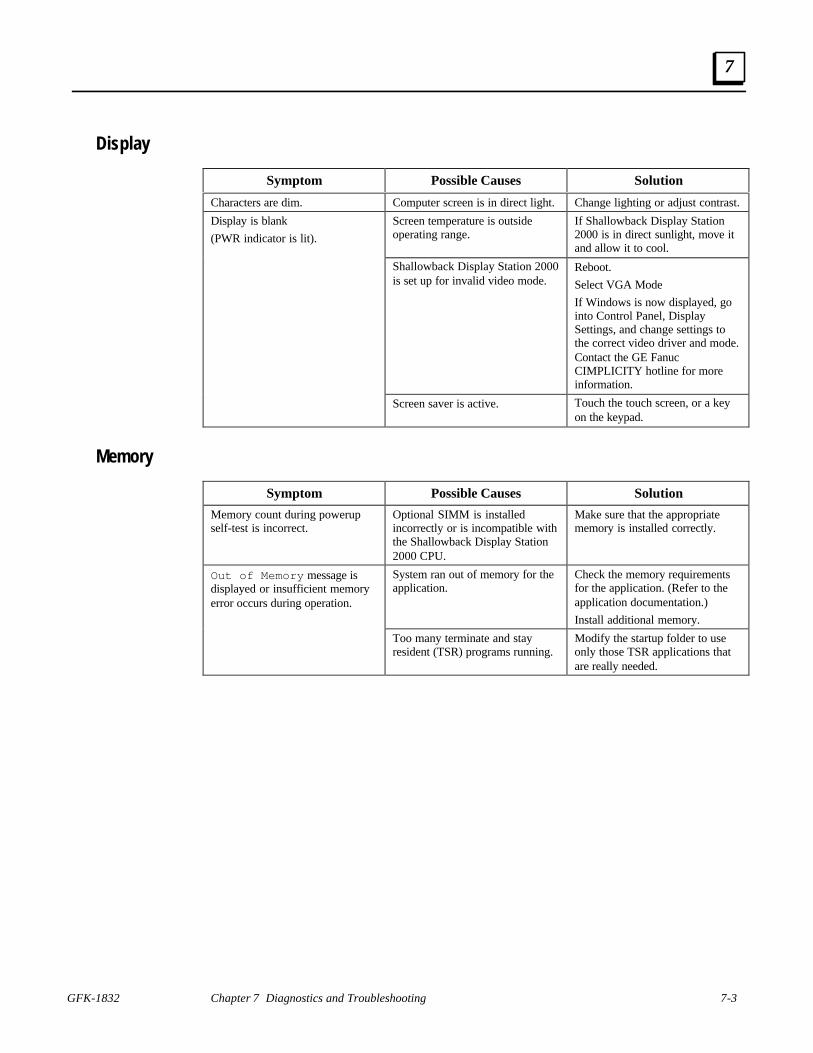
Display
Symptom Possible Causes Solution
Characters are dim. Computer screen is in direct light. Change lighting or adjust contrast.
Display is blank
(PWR indicator is lit).
Screen temperature is outsideoperating range.
If Shallowback Display Station2000 is in direct sunlight, move itand allow it to cool.
Shallowback Display Station 2000is set up for invalid video mode.
Reboot.
Select VGA Mode
If Windows is now displayed, gointo Control Panel, DisplaySettings, and change settings tothe correct video driver and mode.Contact the GE FanucCIMPLICITY hotline for moreinformation.
Screen saver is active. Touch the touch screen, or a keyon the keypad.
Memory
Symptom Possible Causes Solution
Memory count during powerupself-test is incorrect.
Optional SIMM is installedincorrectly or is incompatible withthe Shallowback Display Station2000 CPU.
Make sure that the appropriatememory is installed correctly.
Out of Memory message isdisplayed or insufficient memoryerror occurs during operation.
System ran out of memory for theapplication.
Check the memory requirementsfor the application. (Refer to theapplication documentation.)
Install additional memory.
Too many terminate and stayresident (TSR) programs running.
Modify the startup folder to useonly those TSR applications thatare really needed.

7-4 Shallowback Display Station 2000 User's Guide – July 2000 GFK-1832
7
Touch Screen
Note
Operating temperature can affect touch screen calibration. If touch screenoperation is slightly off, recalibrate it by running calibration from theTouchscreen application in Programs.
Symptom Possible Causes Solution
Cursor does not respond at all totouch.
Touch screen disabled. Make sure that documenteddefault touch screen settings areselected.
Touch screen driver accidentallydeleted.
Reinstall touch screen driver
System is busy. Press Ctrl-Alt-Delete once toview task list.
If Windows NT has been re-installed without modifying theBOOT.INI file, the NTdetectutility will cause problems withthe touch screen.
Modify the BOOT.INI file toinclude the /NoSerialMouseoption. For details, see “ReloadingNT on the Hard Disk From CD” inChapter 2.
Cursor moves but does not followyour touch accurately.
Touch screen not calibratedproperly.
Run calibration from Touchscreenapplication in Programs.
Touch screen responds erraticallyto touch; cursor might not bevisible.
Touch screen settings areincorrect.
Refer to settings.
External PS/2 Mouse
Symptom Possible Causes Solution
Cursor does not respond to mousemovement
Mouse not plugged in. Power down Shallowback DisplayStation 2000. Plug mouse intomouse port on ShallowbackDisplay Station 2000 and reboot.
The type of mouse is notsupported.
Use a PS/2 mouse.
System is busy. Press Ctrl-Alt-Delete to viewtask list.
Mouse not detected. Restart Shallowback DisplayStation 2000 product with externalmouse connected.

GFK-1832 Chapter 7 Diagnostics and Troubleshooting 7-5
7
Keyboard
Symptom Possible Causes Solution
External keyboard locks up The type of keyboard is notsupported.
Use a Key Tronic keyboard. (Mostkeyboards will work. However,we recommend a keyboardmanufactured by Key Tronic.)
Keyboard not plugged intokeyboard port on ShallowbackDisplay Station 2000.
Plug keyboard in.
System is busy. Press Ctrl-Alt-Delete to viewtask list.
Communications
PLC/CPU Connection
Symptom Possible Causes Solution
CIMPLICITY does notcommunicate with a PLC that hasbeen autoconfigured(AUTOCONFIG/DEFAULT/I/Oerror).
The system is attempting tocommunicate with a Series 90-30PLC using the SNP driver and aCIMPLICITY project.
1. With the PLC powered up andconnected to the ShallowbackDisplay Station 2000, establishcommunication between theShallowback Display Station 2000and PLC via the Series 90-30 SNPdriver.
2. Using a Hand-HeldProgrammer, toggle the DefaultI/O (Enable or Disable)configuration parameter for theCPU. Communications betweenthe Shallowback Display Station2000 and the PLC will be stopped.(Communications are stoppedwhen you toggle from Enable toDisable, or vice versa.)
3. Power cycle the PLC.
Communications between the hostcomputer and the controller areunsuccessful.
COM port not configured insystem.
Verify that the COM port isconfigured in the system.
Cabling between computer andcontroller.
Verify that the cable between thecomputer and the controller iscorrectly wired.
Baud rate and parity configuredincorrectly.
Verify that the baud rate andparity on the computer areconsistent with those on thecontroller.
Wrong address. Verify that the slave address iscorrect.

7-6 Shallowback Display Station 2000 User's Guide – July 2000 GFK-1832
7
MODBUS RTU Communications
Symptom Possible Causes Solution
Communications between the hostcomputer and the controller areunsuccessful.
COM port(s) not configured insystem.
Verify that the COM port(s) isconfigured in the system.
Cabling between computer andcontroller.
Verify that the cable between thecomputer and the controller iscorrectly wired.
Baud rate and parity configuredincorrectly.
Verify that baud rate and parity onthe computer are consistent withthose on the controller.
MODBUS port not configured forRTU communications.
Verify that the controller'sMODBUS port is configured forRTU communications.
Wrong address. Verify that the slave address iscorrect.
Network Communications
Symptom Possible Causes Solution
Conflicts on network. IP Address not unique. Change the IP address to a uniqueaddress. (Contact your systemadministrator if this or othersettings need to be changed.)

GFK-1832 Chapter 7 Diagnostics and Troubleshooting 7-7
7
Printing
Symptom Possible Causes Solution
Printer will not turn on. Cables not connected properly.Printer power cord not plugged in.
Ensure that the cables are properlyconnected and that the power cordis connected to the electricaloutlet.
Printer will not print. Printer is not turned on. Turn on the printer
Printer is not online. Set the printer to online.
The device drivers for yourapplication are not installed.
Install the correct printer driversfor your application in Windows.
Printer that is set up for a networkis not connected to the network.
Connect the printer to the network.
Printer cable is too long,unshielded, or defective.
Replace the cable.
Printer is offline. Paper tray is empty. Fill the paper tray with paper. Setprinter to online.
Printer prints garbled information. Correct printer drivers notinstalled.
Install the correct printer driver.
Cable is not connected properly. Ensure that the printer cable isconnected properly to thecomputer.
Problem specific to printer. Run a printer self-test. Refer to thedocumentation provided with yourprinter for instructions. If the self-test fails, the problem is printer-specific. The printing section ofthe software documentation and inWindows online Help may also behelpful.

7-8 Shallowback Display Station 2000 User's Guide – July 2000 GFK-1832
7
Corrective Actions
CMOS Checksum Error
If the CMOS battery has failed, the following error messages will be displayed on the screen:
CMOS checksum error - Defaults loaded
CMOS battery failed
If you see the above message, you can still operate the Shallowback Display Station 2000 bypressing the Delete key and manually setting up the system. (You will need to set up the computereach time the system is powered up.) For setup parameters, refer to “BIOS Settings.”
If the CMOS Battery Fails
This Lithium battery has a lifetime of up to 10 years under normal operating conditions. Lithiumbattery replacement should be done by a factory-trained service person or the unit should bereturned to GE Fanuc for servicing.
If the battery failed, contact the GE Fanuc Technical Service Hotline. North American customersshould call toll-free at 1-800-GE FANUC (1-800-433-2682). International customers should dialdirect: 804-978-6036.

GFK-1832 A-1
Technical Data
Mechanical Specifications
Front Assembly
Each Shallowback Display Station 2000 has the same features and differs only in the size of thescreen:
The two variations include a 15 inch model and an 18 inch model. Both models of the DisplayStation have a touch screen, which provides the operator interface for the unit. There is no integralkeypad. A PC-AT keyboard can be connected for system configuration but is not intended fornormal operator interface use.
Both models have a control/status panel located below the display screen. This panel houses theLED displays which indicate power, IDE drive activity, backlight control and contrast.
The entire front panel assembly is engineered to IP65 standards.
Touch Screen
A resistive touch screen is incorporated in front of the flat screen. The screen is designed so thatimpairment of visibility is reduced to a minimum. The touch screen is bonded to the front metalwork using a silicon sealant.
Main Chassis
The main chassis is manufactured from sheet steel and houses the PC/104 standard boards whichare mounted securely in a horizontal plane.
Four fans provide chassis cooling. A fan mounted directly over the CPU microprocessor providesdirect cooling for that device. In addition two fans are mounted on the bottom of the main chassisadjacent to the power supply, which blow air out of the unit. A fourth fan, which is mounted on theback cover pulls air in through a filter that removes dust and dirt.
AAppendix

A-2 Shallowback Display Station 2000 User's Guide – July 2000 GFK-1832
A
Rear Cover
The rear cover of the unit is fixed to the main chassis so that emissions are minimized. The covercan be removed easily without breaking any electrical connections.
Panel Mounting System
Twelve spring-loaded mounting clamps are provided for mounting the Display Station on a panel.
Functional SpecificationsCPU and Memory
Microprocessor Options Pentium MMX 233 minimum∗User Memory 64 Mbytes Minimum*
Operating System Windows NT
Hard Disk 6 Gbyte minimum*, IDE standard 3.5 inch mounting
Floppy Drive Supports 3.5-inch, 1.44Mb PC format floppy disks
Display
Display Variants 15 inch Color TFT Active Matrix – XGA resolution(1024 x 768)
18 inch Color TFT Active Matrix – SXGA resolution(1280 x 1024)
Active Display Area 15 inch (305 x 229 mm)
18.1 inch (355 x 286 mm)
Power Requirements
AC Input 85 to 265VAC, 200W autoranging
Power Rating 85 to 265V, 47 to 63Hz, 20/4A
PortsParallel Port One: LPT1
Serial Ports COM1 external RS232 port
COM3 external RS232 portCOM2 wired internally to touch screen
Keyboard Port PS/2 connector
Mouse Port PS/2 Connector
USB Ports USB1 and USB2
Ethernet Port 10BaseT port, RJ-45 connector
Video Port 15-pin D-Type connector
Audio Port Standard audio output jack
∗ Contact your local distributor for upgrades.

GFK-1832 Appendix A Technical Data A-3
A
Physical
Dimensions Models with 15-inch display
Models with 18-inch display
434mm (17.08”) wide x 369mm (14.52”) high x 137mm (5.38”) deep
469mm (18.49”) wide x 434mm (17.1”) high x 153mm (6.02”) deep
Weight (base unit asconfigured at factory)
Models with 15-inch display
Models with 18-inch display11.04 Kg (24.35 lbs.)14.51 Kg (32 lbs.)
18.49"
1.86
2.28
1.89
4.50
6.9817.10"
14.52"
17.08"
4.56
14.52
1.8
2.28

A-4 Shallowback Display Station 2000 User's Guide – July 2000 GFK-1832
A
Environmental SpecificationsOperating Temperature 0 to 45°C (0 to 133°F)
Storage Temperature -20° to +60°C (-4° to 140°F)
Relative Humidity 5 to 85% non-condensing
Filter Pad SpecificationsDimensions 80mm by 80mm
Material P15/150B
Performance Requirements Retain 75% by weight of dust particles down to 5-10microns in size
Withstand temperatures to 100° C
Provide flame resistance to BS5588, DIN53438
Note: Filter pads (reference FP80T) are available from:
PAPST-MOTOREN GmbH & Co KGHermann-Papst-Straße 178112 St. Georgen/SchwarzwaldPostfach 14 35
Tel: (0 77 24) 81-0Fax: (0 77 24) 81-309
http://www.papst.de/home.html

Index
GFK-1832 Index-1
AAdjusting the contrast, 5-6Air filter element
changing, 3-5specifications, A-4
Application software, 1-3Audible warning, 2-2
BBacklight dimming control settings, 5-6Backlight modes of operation, 5-7
dim constant, 5-7full constant, 5-7setting timeout period, 5-7timed, 5-7
Battery replacement, 7-8BIOS settings, 6-1
CCables
printer, 4-4serial, 4-3
CD-ROM drive, 5-2Changing hardware configuration settings, 6-1CIMPLICITY HMI software, 1-3CIMPLICITY software
operation, 5-8Clips, retaining, 3-2CMOS
battery, 7-2, 7-8checksum error, 7-8settings, 7-1settings option, 6-1
COM1, COM3location, 4-3pinout, 4-3
Communications, 5-9troubleshooting, 7-5
Configuring networking, 2-3Connectors, 4-1Contrast control, 5-6Control functions, 5-5Control/Status panel, 5-6Corrective Actions, 7-8
DDefault setting
backlight dimming control, 5-7backlight modes of operation, 5-7
Description of system, general, 1-1Diagnostics
bootup sequence, 7-1self-test, 7-1system configuration verification, 7-1system test and initialization, 7-1
Dimensions, A-3Dimming control settings, 5-6Directory structure, 2-5Display
troubleshooting, 7-3Driver
touch screen, 5-5
EEMC radiation specification
complying with, 4-3Environmental specifications, A-4Error messages
AUTOCONFIG/DEFAULT I/O, 7-5, 7-6CMOS battery failed, 7-8CMOS checksum error, 7-2, 7-8CMOS Setup Utility, 7-2Disk Error, 7-2Insufficient memory, 7-3Keyboard failed, 2-1, 6-1Non-fatal, 7-1Non-system disk, 7-2Out of Memory, 7-3
Ethernet adapter, 1-3External devices
caution, 4-1, 4-4External keyboard, 5-4External mouse, 5-4External video, 5-3
FFeatures
optional, 1-3standard, 1-2
Features summary, 1-2Field image recovery disk, 2-7Filters
changing, 3-5specifications, A-4
Floppy Disk Drive, 5-2Functional specifications, A-2
CPU and Memory, A-2display, A-2physical, A-3ports, A-2power requirements, A-2
GGraphics system
display types, 5-3

Index
Index-2 Shallowback Display Station 2000 User's Guide–July 2000 GFK-1832
external video, 5-3graphics controller, 5-3
HHard Disk Drive, 5-2Hardware configuration settings, 6-1Hardware installation, 3-1
II/O, 1-3Image recovery, 2-7Initial startup, 2-1Input power, 4-2Installation
hardware, 3-1Installing a PC104 Card, 3-3Installing application software, 2-5Integrated peripherals setup, 6-1
KKeyboard
error message, 2-1external, 5-4troubleshooting, 7-5
LLithium battery, 7-8Login recommendation, 2-4LPT1
location, 4-4pinout, 4-4
MMechanical specifications , A-1
front assembly, A-1main chassis, A-1panel mounting system, A-2rear cover, A-2touch screen, A-1
Memorytroubleshooting, 7-3
Microsoftnetwork configuration, 2-3
MODBUS RTU communicationstroubleshooting, 7-6
Mode setting, 5-7Mounting guidelines, 3-1Mounting procedure, 3-2Mouse
external, 5-4
NNetwork communications
troubleshooting, 7-6Network components, 5-6, 5-9Network configuration, 2-3Network interface, 1-3
OOperation, system, 5-1Operator interfaces, 5-4
external keyboard, 5-4external mouse, 5-4touch screen, 5-4
PParallel cables, 4-4PC104 expansion, 1-3Peripherals, 5-2PLC/CPU connection
troubleshooting, 7-5Power input, 4-2
AC models, 4-2Powering up, 2-2
troubleshooting, 7-2Printer cables, 4-4Printing
troubleshooting, 7-7
RRecovery, image, 2-7Registering your CIMPLICITY software, 2-4Reset
accidental, 7-2Retaining clips, 3-2
SSelf-test diagnostics, 7-1Serial cables
complying with EMC radiation specificaton, 4-3Serial communication cables, 4-3Serial Mouse
troubleshooting, 7-4Setting up Windows NT systems, 2-2Setting, mode, 5-7Setup
integrated peripherals, 6-1Shallowback Display Station 2000, 1-1
description of features, 1-1functional specifications, A-2

Index
GFK-1832 Index Index-3
mechanical specifications, A-1technical data, A-1
Shutting down the computer, 2-7Specifications
environmental, A-4functional, A-2mechanical, A-1
Spring loaded clips, 3-2Standard I/O Interface Channels
COM1, COM2 serial ports, 1-3LPT1 parallel port, 1-3USB1 and USB2 Universal Serial Bus ports, 1-3
Summary of features, 1-2System architecture, 1-1System Configuration Verification, 7-1System description, 1-1System I/O, 1-3System operation, 5-1System peripherals
CD-ROM drive, 5-2floppy disk drive, 5-2hard disk drive, 5-2
System Test and Initialization, 7-1
TTechnical data, A-1Temperature
effect on contrast setting, 7-3Timeout period, backlight, setting, 5-7Touch screen, 5-4
driver, 5-5driver factory default settings, 2-6troubleshooting, 7-4
Troubleshooting, 7-2communications, 7-5display, 7-3keyboard, 7-5memory, 7-3MODBUS RTU communications, 7-6network communications, 7-6PLC/CPU connection, 7-5powerup, 7-2printing, 7-7serial mouse, 7-4touch screen, 7-4
TSRs, 7-3
VVideo
external, 5-3
WWarning, audible, 2-2


