
G.fast Certification Abstract Test PlanG.fast Certification Abstract Test Plan ATP-337 Issue 1 July...
83
ABSTRACT TEST PLAN © The Broadband Forum. All rights reserved. ATP-337 G.fast Certification Abstract Test Plan Issue: 1 Issue Date: July 2017
Transcript of G.fast Certification Abstract Test PlanG.fast Certification Abstract Test Plan ATP-337 Issue 1 July...

ABSTRACT TEST PLAN
© The Broadband Forum. All rights reserved.
ATP-337
G.fast Certification Abstract Test Plan
Issue: 1
Issue Date: July 2017

G.fast Certification Abstract Test Plan ATP-337 Issue 1
July 2017 © The Broadband Forum. All rights reserved 2 of 83
Notice
The Broadband Forum is a non-profit corporation organized to create guidelines for broadband
network system development and deployment. This Abstract Test Plan has been approved by
members of the Forum. This Abstract Test Plan is subject to change. This Abstract Test Plan is
copyrighted by the Broadband Forum, and all rights are reserved. Portions of this Abstract Test
Plan may be copyrighted by Broadband Forum members.
Intellectual Property
Recipients of this Abstract Test Plan are requested to submit, with their comments, notification of
any relevant patent claims or other intellectual property rights of which they may be aware that
might be infringed by any implementation of this Abstract Test Plan, or use of any software code
normatively referenced in this Abstract Test Plan, and to provide supporting documentation.
Terms of Use
1. License Broadband Forum hereby grants you the right, without charge, on a perpetual, non-exclusive and
worldwide basis, to utilize the Abstract Test Plan for the purpose of developing, making, having
made, using, marketing, importing, offering to sell or license, and selling or licensing, and to
otherwise distribute, products complying with the Abstract Test Plan, in all cases subject to the
conditions set forth in this notice and any relevant patent and other intellectual property rights of
third parties (which may include members of Broadband Forum). This license grant does not
include the right to sublicense, modify or create derivative works based upon the Abstract Test Plan
except to the extent this Abstract Test Plan includes text implementable in computer code, in which
case your right under this License to create and modify derivative works is limited to modifying and
creating derivative works of such code. For the avoidance of doubt, except as qualified by the
preceding sentence, products implementing this Abstract Test Plan are not deemed to be derivative
works of the Abstract Test Plan.
2. NO WARRANTIES
THIS ABSTRACT TEST PLAN IS BEING OFFERED WITHOUT ANY WARRANTY
WHATSOEVER, AND IN PARTICULAR, ANY WARRANTY OF NONINFRINGEMENT IS
EXPRESSLY DISCLAIMED. ANY USE OF THIS ABSTRACT TEST PLAN SHALL BE MADE
ENTIRELY AT THE IMPLEMENTER'S OWN RISK, AND NEITHER THE BROADBAND
FORUM, NOR ANY OF ITS MEMBERS OR SUBMITTERS, SHALL HAVE ANY LIABILITY
WHATSOEVER TO ANY IMPLEMENTER OR THIRD PARTY FOR ANY DAMAGES OF
ANY NATURE WHATSOEVER, DIRECTLY OR INDIRECTLY, ARISING FROM THE USE
OF THIS ABSTRACT TEST PLAN.
3. THIRD PARTY RIGHTS Without limiting the generality of Section 2 above, BROADBAND FORUM ASSUMES NO
RESPONSIBILITY TO COMPILE, CONFIRM, UPDATE OR MAKE PUBLIC ANY THIRD
PARTY ASSERTIONS OF PATENT OR OTHER INTELLECTUAL PROPERTY RIGHTS
THAT MIGHT NOW OR IN THE FUTURE BE INFRINGED BY AN IMPLEMENTATION OF
THE ABSTRACT TEST PLAN IN ITS CURRENT, OR IN ANY FUTURE FORM. IF ANY

G.fast Certification Abstract Test Plan ATP-337 Issue 1
July 2017 © The Broadband Forum. All rights reserved 3 of 83
SUCH RIGHTS ARE DESCRIBED ON THE ABSTRACT TEST PLAN, BROADBAND FORUM
TAKES NO POSITION AS TO THE VALIDITY OR INVALIDITY OF SUCH ASSERTIONS,
OR THAT ALL SUCH ASSERTIONS THAT HAVE OR MAY BE MADE ARE SO LISTED.
The text of this notice must be included in all copies of this Abstract Test Plan.
© 2017, The Broadband Forum. All rights reserved. This Broadband Forum document
(ATP-337) specifies the Test Plan on which is based the Gfast Certification Program for
G.fast products. Through an open selection process, the Broadband Forum entered into an
agreement with one or more independent Test Agencies to offer commercial testing services
against this Test Plan and to confirm results to the Broadband Forum in connection with
the Forum's delivery of Gfast Certification. Offering Certification testing services against
this Test Plan is reserved to the Test Agencies duly authorized by the Broadband Forum.
Broadband Forum members can independently test against ATP-337, but may only
produce limited reports which only detail where a given product has failed a test case
NOTE: The right to display a Broadband Forum Certification Logo may only be
granted by the Broadband Forum, and that right is available only to Broadband Forum
members that have successfully passed certification testing by a duly authorized Test
Agency. Further details on the Broadband Forum Certification Programs can be found
at http://www.broadband-forum.org

G.fast Certification Abstract Test Plan ATP-337 Issue 1
July 2017 © The Broadband Forum. All rights reserved 4 of 83
Issue History
Issue Number Approval Date Publication Date Issue Editor Changes
1 24 July 2017 10 October 2017 Frank Van der
Putten, Nokia
Original
Comments or questions about this Broadband Forum Abstract Test Plan should be directed to
Editor Frank Van der
Putten
Nokia [email protected]
Physical Layer
Transmission
WA Directors
Les Brown Huawei
Technologies
G.fast & RPF
Certification Testing
PS Leaders
Les Brown Huawei
Technologies
Frank Van der
Putten
Nokia [email protected]
G.fast Certification Abstract Test Plan ATP-337 Issue 1
July 2017 © The Broadband Forum. All rights reserved 5 of 83
Table of Contents
EXECUTIVE SUMMARY .............................................................................................................. 12
1 PURPOSE AND SCOPE ......................................................................................................... 13
1.1 PURPOSE.............................................................................................................................. 13
1.2 SCOPE .................................................................................................................................. 13 1.3 COMPLIANCE REQUIREMENTS ............................................................................................. 14 1.4 TEST PLAN PASSING CRITERIA ............................................................................................. 14
2 REFERENCES AND TERMINOLOGY ............................................................................... 15
2.1 CONVENTIONS ..................................................................................................................... 15
2.2 REFERENCES ....................................................................................................................... 15 2.3 DEFINITIONS ........................................................................................................................ 16
2.4 ABBREVIATIONS .................................................................................................................. 17
3 ABSTRACT TEST PLAN IMPACT ...................................................................................... 19
3.1 ENERGY EFFICIENCY ........................................................................................................... 19 3.2 IPV6 .................................................................................................................................... 19
3.3 SECURITY ............................................................................................................................ 19 3.4 PRIVACY.............................................................................................................................. 19
4 EQUIPMENT FEATURES ..................................................................................................... 20
4.1 DEVICE UNDER TEST (DUT) AND LINK PARTNER INFORMATION ........................................ 20 4.2 MANAGEMENT OF THE DUT AND LINK PARTNER ............................................................... 20
5 TEST ENVIRONMENTS ........................................................................................................ 22
5.1 TEST CONFIGURATIONS ....................................................................................................... 22
5.1.1 Ethernet/IP Traffic Setup ............................................................................................... 22 5.1.2 Ethernet traffic frame sizes ............................................................................................ 25 5.1.3 Physical Layer Test Setup .............................................................................................. 25
5.2 TEST SETUP CHARACTERISTICS ........................................................................................... 27 5.2.1 Temperature and Humidity ............................................................................................ 27 5.2.2 Loops environment characteristics ................................................................................ 27
5.3 DEVICE UNDER TEST (DUT) AND LINK PARTNER SETTINGS ............................................... 28 5.3.1 Profile settings ................................................................................................................ 28 5.3.2 Time division duplexing (TDD) settings ......................................................................... 28
5.3.3 Power and spectrum usage settings ............................................................................... 29
5.3.4 Noise margin (SNRM) settings ....................................................................................... 29 5.3.5 Seamless Rate Adaptation (SRA) settings ...................................................................... 30 5.3.6 Fast Rate Adaptation (FRA) settings ............................................................................. 30 5.3.7 Robust Management Channel (RMC) settings ............................................................... 31 5.3.8 Vectoring settings ........................................................................................................... 31
5.3.9 Re-initilaization policy settings ...................................................................................... 32 5.3.10 Update of test parameters settings ............................................................................. 32 5.3.11 Data rates settings ...................................................................................................... 32
5.3.12 Retransmission settings .............................................................................................. 33
G.fast Certification Abstract Test Plan ATP-337 Issue 1
July 2017 © The Broadband Forum. All rights reserved 6 of 83
5.3.13 Data path settings ....................................................................................................... 33 5.4 TEST SETUP ......................................................................................................................... 34
5.4.1 Test Loop Topologies ..................................................................................................... 34 5.4.2 PSD Test Jig ................................................................................................................... 38
5.4.3 TIGA Test Jig ................................................................................................................. 38 5.4.4 Noise Models .................................................................................................................. 41 5.4.5 Noise injection ................................................................................................................ 50 5.4.6 Test Equipment Requirements ........................................................................................ 51 5.4.7 Management of the DUT and Link Partner ................................................................... 52
6 FUNCTIONAL TESTS............................................................................................................ 53
6.1 INVENTORY DATA TEST ....................................................................................................... 53
6.1.1 Purpose ........................................................................................................................... 53 6.1.2 Certification Requirement .............................................................................................. 54 6.1.3 References ...................................................................................................................... 54 6.1.4 Test Setup ....................................................................................................................... 54
6.1.5 Method of Procedure ...................................................................................................... 54 6.1.6 Report ............................................................................................................................. 54 6.1.7 Expected Results ............................................................................................................. 54
6.1.8 Estimated Test Time ....................................................................................................... 54 6.2 PSD MASK TESTS ............................................................................................................... 54
6.2.1 PSD Limit Mask Test ...................................................................................................... 55
6.2.2 Sub-carrier Masking Test ............................................................................................... 56 6.2.3 PSD Shaping Test ........................................................................................................... 56
6.2.4 RFI Notching Test .......................................................................................................... 57 6.2.5 UPBO Test ...................................................................................................................... 58
6.2.6 TIGA Test ....................................................................................................................... 59 6.3 TDD OPERATIONS ............................................................................................................... 59
6.3.1 TDD Inter-frame Gap Test ............................................................................................. 60
6.3.2 DS and US ratio configuration (Mds) Test .................................................................... 60 6.4 ACCELERATED MTBE TEST ................................................................................................ 61
6.4.1 Purpose ........................................................................................................................... 61 6.4.2 Certification Requirement .............................................................................................. 61 6.4.3 References ...................................................................................................................... 62
6.4.4 Test Setup ....................................................................................................................... 62 6.4.5 Method of Procedure ...................................................................................................... 62
6.4.6 Report ............................................................................................................................. 62 6.4.7 Expected Results ............................................................................................................. 62
6.4.8 Estimated Test Time ....................................................................................................... 62 6.5 DISCONTINUOUS OPERATION TEST ...................................................................................... 62
6.5.1 Purpose ........................................................................................................................... 62 6.5.2 Certification Requirement .............................................................................................. 62 6.5.3 References ...................................................................................................................... 62
6.5.4 Test Setup ....................................................................................................................... 63 6.5.5 Method of Procedure ...................................................................................................... 63 6.5.6 Report ............................................................................................................................. 63
6.5.7 Expected Results ............................................................................................................. 63
G.fast Certification Abstract Test Plan ATP-337 Issue 1
July 2017 © The Broadband Forum. All rights reserved 7 of 83
6.5.8 Estimated Test Time ....................................................................................................... 63 6.6 BIT SWAP TEST .................................................................................................................... 63
6.6.1 Purpose ........................................................................................................................... 63 6.6.2 Certification Requirement .............................................................................................. 63
6.6.3 References ...................................................................................................................... 63 6.6.4 Test Setup ....................................................................................................................... 63 6.6.5 Method of Procedure ...................................................................................................... 63 6.6.6 Report ............................................................................................................................. 63 6.6.7 Expected Results ............................................................................................................. 64
6.6.8 Estimated Test Time ....................................................................................................... 64 6.7 SRA DOWNSHIFT TEST ....................................................................................................... 64
6.7.1 Purpose ........................................................................................................................... 64
6.7.2 Certification Requirement .............................................................................................. 64 6.7.3 References ...................................................................................................................... 64 6.7.4 Test Setup ....................................................................................................................... 64
6.7.5 Method of Procedure ...................................................................................................... 64 6.7.6 Report ............................................................................................................................. 64 6.7.7 Expected Results ............................................................................................................. 64
6.7.8 Estimated Test Time ....................................................................................................... 64 6.8 SRA UPSHIFT TEST ............................................................................................................. 65
6.8.1 Purpose ........................................................................................................................... 65
6.8.2 Certification Requirement .............................................................................................. 65 6.8.3 References ...................................................................................................................... 65
6.8.4 Test Setup ....................................................................................................................... 65
6.8.5 Method of Procedure ...................................................................................................... 65
6.8.6 Report ............................................................................................................................. 65 6.8.7 Expected Results ............................................................................................................. 65 6.8.8 Estimated Test Time ....................................................................................................... 65
6.9 FRA & SRA UPSHIFT TEST................................................................................................. 65 6.9.1 Purpose ........................................................................................................................... 65
6.9.2 Certification Requirement .............................................................................................. 66 6.9.3 References ...................................................................................................................... 66 6.9.4 Test Setup ....................................................................................................................... 66
6.9.5 Method of Procedure ...................................................................................................... 66 6.9.6 Report ............................................................................................................................. 67 6.9.7 Expected Results ............................................................................................................. 67 6.9.8 Estimated Test Time ....................................................................................................... 67
6.10 RPA TEST ........................................................................................................................... 67 6.10.1 Purpose ....................................................................................................................... 67 6.10.2 Certification Requirement .......................................................................................... 67 6.10.3 References .................................................................................................................. 67 6.10.4 Test Setup ................................................................................................................... 67
6.10.5 Method of Procedure .................................................................................................. 67 6.10.6 Report ......................................................................................................................... 67 6.10.7 Expected Results ......................................................................................................... 67 6.10.8 Estimated Test Time ................................................................................................... 68

G.fast Certification Abstract Test Plan ATP-337 Issue 1
July 2017 © The Broadband Forum. All rights reserved 8 of 83
6.11 RMC BIT LOADING CONFIGURATION TEST .......................................................................... 68 6.11.1 Purpose ....................................................................................................................... 68 6.11.2 Certification Requirement .......................................................................................... 68 6.11.3 References .................................................................................................................. 68
6.11.4 Test Setup ................................................................................................................... 68 6.11.5 Method of Procedure .................................................................................................. 68 6.11.6 Report ......................................................................................................................... 68 6.11.7 Expected Results ......................................................................................................... 68 6.11.8 Estimated Test Time ................................................................................................... 68
6.12 RE-INITIALIZATION POLICY TEST ........................................................................................ 68 6.12.1 Short disconnect Test ................................................................................................. 69 6.12.2 Long disconnect Test with LOS failure ...................................................................... 69
6.12.3 Long disconnect Test with LOR failure ...................................................................... 70 6.13 DYING GASP TEST ............................................................................................................... 71
6.13.1 Purpose ....................................................................................................................... 71
6.13.2 Certification Requirement .......................................................................................... 71 6.13.3 References .................................................................................................................. 71 6.13.4 Test Setup ................................................................................................................... 71
6.13.5 Method of Procedure .................................................................................................. 71 6.13.6 Report ......................................................................................................................... 71 6.13.7 Expected Results ......................................................................................................... 72
6.13.8 Estimated Test Time ................................................................................................... 72
7 STABILITY TESTS ................................................................................................................. 72
7.1 SHINE STABILITY TEST ...................................................................................................... 72 7.1.1 Purpose ........................................................................................................................... 72
7.1.2 Certification Requirement .............................................................................................. 72 7.1.3 References ...................................................................................................................... 72 7.1.4 Test Setup ....................................................................................................................... 72
7.1.5 Method of Procedure ...................................................................................................... 72 7.1.6 Report ............................................................................................................................. 72
7.1.7 Expected Results ............................................................................................................. 73 7.1.8 Estimated Test Time ....................................................................................................... 73
7.2 REIN STABILITY TEST......................................................................................................... 73
7.2.1 Purpose ........................................................................................................................... 73 7.2.2 Certification Requirement .............................................................................................. 73
7.2.3 References ...................................................................................................................... 73 7.2.4 Test Setup ....................................................................................................................... 73
7.2.5 Method of Procedure ...................................................................................................... 73 7.2.6 Report ............................................................................................................................. 73 7.2.7 Expected Results ............................................................................................................. 73 7.2.8 Estimated Test Time ....................................................................................................... 74
7.3 FLUCTUATING BROADBAND RFI NOISE PRESENT AT INITIALIZATION TEST ........................ 74
7.3.1 Purpose ........................................................................................................................... 74 7.3.2 Certification Requirement .............................................................................................. 74 7.3.3 References ...................................................................................................................... 74
7.3.4 Test Setup ....................................................................................................................... 74

G.fast Certification Abstract Test Plan ATP-337 Issue 1
July 2017 © The Broadband Forum. All rights reserved 9 of 83
7.3.5 Method of Procedure ...................................................................................................... 74 7.3.6 Report ............................................................................................................................. 74 7.3.7 Expected Results ............................................................................................................. 74 7.3.8 Estimated Test Time ....................................................................................................... 74
7.4 STATIONARY BROADBAND RFI NOISE PRESENT AT INITIALIZATION TEST .......................... 74 7.4.1 Purpose ........................................................................................................................... 75 7.4.2 Certification Requirement .............................................................................................. 75 7.4.3 References ...................................................................................................................... 75 7.4.4 Test Setup ....................................................................................................................... 75
7.4.5 Method of Procedure ...................................................................................................... 75 7.4.6 Report ............................................................................................................................. 75 7.4.7 Expected Results ............................................................................................................. 75
7.4.8 Estimated Test Time ....................................................................................................... 75 7.5 FLUCTUATING BROADBAND RFI NOISE PRESENT AT SHOWTIME TEST ............................... 75
7.5.1 Purpose ........................................................................................................................... 75
7.5.2 Certification Requirement .............................................................................................. 75 7.5.3 References ...................................................................................................................... 76 7.5.4 Test Setup ....................................................................................................................... 76
7.5.5 Method of Procedure ...................................................................................................... 76 7.5.6 Report ............................................................................................................................. 76 7.5.7 Expected Results ............................................................................................................. 76
7.5.8 Estimated Test Time ....................................................................................................... 76 7.6 STATIONARY BROADBAND RFI NOISE PRESENT AT SHOWTIME TEST ................................. 76
7.6.1 Purpose ........................................................................................................................... 76
7.6.2 Certification Requirement .............................................................................................. 76
7.6.3 References ...................................................................................................................... 76 7.6.4 Test Setup ....................................................................................................................... 76 7.6.5 Method of Procedure ...................................................................................................... 77
7.6.6 Report ............................................................................................................................. 77 7.6.7 Expected Results ............................................................................................................. 77
7.6.8 Estimated Test Time ....................................................................................................... 77
8 PERFORMANCE TESTS ....................................................................................................... 78
8.1 SINGLE-LINE PERFORMANCE TESTS .................................................................................... 78
8.1.1 Single-line Basic Throughput Test ................................................................................. 78 8.2 MULTI-LINE PERFORMANCE TESTS ..................................................................................... 78
8.2.1 Multi-line Basic Throughput Test .................................................................................. 79 8.2.2 Multi-line Disorderly Shutdown Test ............................................................................. 80
APPENDIX I EXAMPLE MEASUREMENT SYSTEMS FOR PSD MASK TESTING ..... 81
APPENDIX II SUMMARY OF THE TESTS AND THE ESTIMATED TEST TIMES .... 82
G.fast Certification Abstract Test Plan ATP-337 Issue 1
July 2017 © The Broadband Forum. All rights reserved 10 of 83
List of Figures
Figure 1 - Test setup for Ethernet/IP traffic with single line test ....................................................... 22 Figure 2 - Test setup for Ethernet/IP traffic with multi-line test ........................................................ 23
Figure 3 - One instance of a Physical Layer Test Setup (test loop topology and noise injection) ..... 26 Figure 4 - One instance of a Physical Layer Test Setup (PSD or TIGA Test Jig or Test Loop
Topology and measurement system) .......................................................................................... 27 Figure 5 - Multi-Pair Cable Test Loop Topology .............................................................................. 34 Figure 6 - Home Network Bridged Tap Test Loop Topology ........................................................... 37
Figure 7 - PSD Test Jig ...................................................................................................................... 38 Figure 8 - TIGA Test Jig for the downstream direction ..................................................................... 39 Figure 9 - PSD of the Band-limited Noise of Type 1 and 2. .............................................................. 42
Figure 10 - PSD of the Band-limited Noise of Type 3 to 6. .............................................................. 43 Figure 11 - The PSD of a single REIN burst ...................................................................................... 49 Figure 12 - Norton Equivalent Circuit Diagram ................................................................................ 50
Figure 13 - Illustration of the noise changes and related transceiver actions. ................................... 66
List of Tables
Table 1 - DPU Information ................................................................................................................ 20 Table 2 - CPE Information ................................................................................................................. 20
Table 3 - Ethernet/IP test frame definition ......................................................................................... 24 Table 4 - Ethernet/IP frame parameter values .................................................................................... 24
Table 5 - Frame Size Distribution within Ethernet Traffic ................................................................ 25
Table 6 - Temperature and Humidity Range of Test Facility ............................................................ 27
Table 7 - Loops used for Testing ....................................................................................................... 28 Table 8 - G.fast profile configuration ................................................................................................. 28 Table 9 - TDD configuration .............................................................................................................. 28
Table 10 - Power spectrum usage configuration ................................................................................ 29 Table 11 - Noise margin configuration .............................................................................................. 30
Table 12 - SRA configuration ............................................................................................................ 30 Table 13 - FRA configuration ............................................................................................................ 30 Table 14 - RMC configuration ........................................................................................................... 31
Table 15 - Vectoring configuration for multi-port DPU .................................................................... 31 Table 16 - Re-initialization policy configuration ............................................................................... 32 Table 17 - Update of test parameters configuration ........................................................................... 32 Table 18 - Downstream and upstream channel data rates configuration ........................................... 33
Table 19 - Downstream and upstream retransmission configuration ................................................. 33 Table 20 - Data path configuration .................................................................................................... 33 Table 21 - MIN and MAX limits for direct path VTF ....................................................................... 40 Table 22 - MIN and MAX limits for ELFEXT .................................................................................. 40 Table 23 - Differential Mode Carrier Powers for Total RFI Signal, RFI (t) - Fluctuating Broadband
RFI Case ..................................................................................................................................... 45 Table 24 - Differential Mode Carrier Powers and Signal Structure for RFI Signal- FM Broadcast. 47 Table 25 - Differential Mode Carrier Powers and Signal Structure for RFI Signal- TV ................... 48 Table 26 - REIN time domain characteristics .................................................................................... 48

G.fast Certification Abstract Test Plan ATP-337 Issue 1
July 2017 © The Broadband Forum. All rights reserved 11 of 83
Table 27 - SHINE time domain characteristics .................................................................................. 49 Table 28 - Parameters as applicable to the DUT ................................................................................ 53 Table 29 - PSD Frequency Range ...................................................................................................... 55
G.fast Certification Abstract Test Plan ATP-337 Issue 1
July 2017 © The Broadband Forum. All rights reserved 12 of 83
Executive Summary
This Broadband Forum Abstract Test Plan, ATP-337 Issue 1, provides a set of functional, stability
and basic performance test cases and related pass/fail requirements for G.fast implementations
according to ITU-T Recommendations G.9700 [1] and G.9701 [2].
The primary goal of ATP-337 Issue 1 is to provide a set of test cases and framework to verify
interoperability between an FTU-O (e.g., a DPU) and one or more FTU-Rs (e.g., CPEs ).
Issue 1 of ATP-337 serves as the test plan, including pass/fail requirements for each test case, for
the Broadband Forum G.fast Certification Program. Technical content in this test plan includes test
setup information, equipment configuration requirements, test procedures, and pass/fail
requirements for each test case, through a reference to the full text within IR-337 [11]. The full
IR-337 is available to Broadband Forum members in good standing, and may be downloaded from
the Broadband Forum website.
For additional details about the G.fast Certification Program, including requirements for
participation in the program or to view the list of currently certified devices, please refer to the
Broadband Forum website.

G.fast Certification Abstract Test Plan ATP-337 Issue 1
July 2017 © The Broadband Forum. All rights reserved 13 of 83
1 Purpose and Scope
1.1 Purpose
ATP-337 Issue 1 provides a set of functional, stability and basic performance test cases and related
pass/fail requirements for G.fast implementations according to ITU-T Recommendations G.9700
[1] and G.9701 [2].
The primary goal of ATP-337 Issue 1 is to provide a set of test cases and framework to verify
interoperability between an FTU-O (e.g., a DPU) and one or more FTU-Rs (e.g., CPEs). The test
cases are defined for a Device Under Test (DUT – either a DPU or CPE), tested against a Link
Partner (either a CPE or DPU respectively). The DPU/CPE may be a reference design, however
containing the necessary FTU-O/R and system functionality to execute this test plan (see e.g.,
section 4.2).
Issue 1 of ATP-337 serves as the test plan, including pass/fail requirements for each test case, for
the Broadband Forum G.fast Certification Program. Additional documentation is available from the
Broadband Forum about the G.fast Certification Program, including program benefits, participation
requirements, number and type of equipment to be tested against, and logo usage guidelines. For
additional details about the Broadband Forum’s certification programs, please refer to:
https://www.broadband-forum.org/technical/test_cert_programs.php.
The reader is directed to the formal certification program documentation, which can be downloaded
from the Broadband Forum’s public website, for a full description of the certification requirements
and procedures.
Technical content in this test plan includes test setup information, equipment configuration
requirements, test procedures, and pass/fail requirements for each test case. Specific manufacturer
information for test and measurement equipment has not been included in this document, except in
cases where the selection or use of alternate equipment could negatively impact the results of the
testing.
1.2 Scope
This Abstract Test Plan is intended to provide a certification test plan for ITU-T Recommendation
G.9700 “Fast access to subscriber terminals (G.fast) – Power spectral density specification” and
G.9701 “Fast access to subscriber terminals (G.fast) – Physical layer specification”. This Issue 1 is
specifically conceived for the basic interoperability objectives of the Broadband Forum G.fast
Certification Program.
Issue 1 of ATP-337 is intended to address a common set of basic test scenarios that can apply to
different deployments around the world. The test scenarios have been developed based on
deployment scenarios in the Fiber to the Distribution Point (FTTdp) architecture as defined by
Broadband Forum in TR-301 [5]. Test cases included in ATP-337 Issue 1 are intended to verify the
interoperability between an FTU-O and an FTU-R (or multiple FTU-Rs) according to:
functionality of mandatory features within the G.9700 and G.9701 specifications,
basic performance between two or more transceivers,

G.fast Certification Abstract Test Plan ATP-337 Issue 1
July 2017 © The Broadband Forum. All rights reserved 14 of 83
stability and quality of the connection.
Operator specific scenarios, including testing with loop types, lengths, or noise scenarios, that may
be specific to a deployment, are outside the scope of Issue 1 of this document. This Test Plan is
applicable to both single-port and multi-port DPUs, test cases applicable only to multi-port DPUs
are clearly identified as conditional test cases.
This test plan is not intended to replace operator pre-deployment testing, which may include
additional tests for a given deployment.
1.3 Compliance requirements
The tests contained in this document are intended to verify the interoperability between an FTU-R
implementation and an FTU-O implementation, while also testing the DUT’s compliance to the
ITU-T specifications in some key functional areas, such as transmit power, upstream/downstream
split ratios, etc. This test plan is not intended to validate completely a DUT’s compliance to the
ITU-T specifications. Instead these other key aspects of the specification are tested for
interoperability with the link partner.
1.4 Test plan passing criteria
The tests contained in this document are each marked with a test status, indicating: “mandatory,”
“conditional mandatory,” or “optional.” These terms are defined in section 2.3.
For the purpose of determining a summary result, such as indicating a device “passes ATP-337
testing,” the device SHALL pass all “mandatory” tests and all applicable “conditional mandatory”
tests. “Optional” tests SHALL not impact the summary result. For the purposes of certification, this
test plan only defines the requirements for each individual test case, while the certification program
might require passing additional tests or testing with multiple link partners to achieve certification.
For some tests, parameters are recorded for reporting purposes only. These parameters might be
useful for debugging purposes.
G.fast Certification Abstract Test Plan ATP-337 Issue 1
July 2017 © The Broadband Forum. All rights reserved 15 of 83
2 References and Terminology
2.1 Conventions
In this Abstract Test Plan, several words are used to signify the requirements of the specification.
These words are always capitalized. More information can be found in RFC 2119 [3].
SHALL This word, or the term “REQUIRED”, means that the definition is an
absolute requirement of the specification.
SHALL NOT This phrase means that the definition is an absolute prohibition of the
specification.
SHOULD This word, or the adjective “RECOMMENDED”, means that there
may exist valid reasons in particular circumstances to ignore this item,
but the full implications need to be understood and carefully weighed
before choosing a different course.
SHOULD NOT This phrase, or the phrase “NOT RECOMMENDED” means that there
may exist valid reasons in particular circumstances when the particular
behavior is acceptable or even useful, but the full implications should
be understood and the case carefully weighed before implementing
any behavior described with this label.
MAY This word, or the adjective “OPTIONAL”, means that this item is one
of an allowed set of alternatives. An implementation that does not
include this option SHALL be prepared to inter-operate with another
implementation that does include the option.
2.2 References
The following references are of relevance to this Abstract Test Plan. At the time of publication, the
editions indicated were valid. All references are subject to revision; users of this Abstract Test Plan
are therefore encouraged to investigate the possibility of applying the most recent edition of the
references listed below.
A list of currently valid Broadband Forum Technical Reports is published at www.broadband-
forum.org.
Document Title Source Year
[1] G.9700 Fast Access to Subscriber
Terminals (G.fast) –
Power spectrum density
specification
ITU-T 2014

G.fast Certification Abstract Test Plan ATP-337 Issue 1
July 2017 © The Broadband Forum. All rights reserved 16 of 83
[2] G.9701 Fast Access to Subscriber
Terminals (G.fast) –
Physical layer
specification
ITU-T 2014
[3] RFC 2119 Key words for use in RFCs
to Indicate Requirement
Levels
IETF 1997
[4] TR-114 Issue 2 VDSL2 Performance Test
Plan – Issue 2
Broadband Forum 2012
[5] TR-301 Fiber To The Distribution
Point
Broadband Forum 2015
[6] G.227 Conventional Telephone
Signal
ITU-T 1998
[7] RFC 791 Internet Protocol IETF 1981
[8] TR-285 Broadband Copper Cable
Models
Broadband Forum 2015
[9] G.997.2 Physical Layer OAM for
G.fast
ITU-T 2015
[10] TS 101 388 Asymmetric Digital
Subscriber Line (ADSL) -
European specific
requirements - [ITU-T
Recommendation G.992.1
modified]
ETSI TC ATTM 2007
[11] IR-337 G.fast Certification Test
Plan
Broadband Forum 2017
2.3 Definitions
The following terminology is used throughout this Abstract Test Plan.
Conditional
mandatory
Tests marked as “conditional mandatory” also include a conditional statement;
which if met, indicates the test SHALL be considered as “mandatory.” If the
conditional statement is not met, the test SHALL be considered as “optional” or
“not applicable.”
Link Partner Applicable device to connect to the test setup opposite the device under test
(DUT). For example, if the DUT is a CPE device, the Link Partner is a DPU
device.
Mandatory Tests marked as “mandatory” SHALL be performed when completing testing
according to this test plan.
Optional Tests marked as “optional” MAY be completed at the request of the tester or
equipment manufacturer.

G.fast Certification Abstract Test Plan ATP-337 Issue 1
July 2017 © The Broadband Forum. All rights reserved 17 of 83
2.4 Abbreviations
This Abstract Test Plan uses the following abbreviations:
AC Alternating Current
AM Amplitude Modulation
AGN Additive Gaussian Noise
AWGN Additive White Gaussian Noise
CPE Customer Premises Equipment
DMT Discrete Multi-Tone
DPU Distribution Point Unit
DSL Digital Subscriber Line
DTU Data Transfer Unit
DUT Device Under Test
ETR Expected Throughput
FLR Frame Loss Ratio
FM Frequency Modulation
FRA Fast Rate Adaptation
FTU G.fast Transceiver Unit
FTU-O FTU at the Optical Network Unit (i.e., operator end of the loop)
FTU-R FTU at the Remote site (i.e., subscriber end of the loop)
GDR Gamma Data Rate
G.fast Fast access to subscriber terminals
HON Higher Order Node
LAN Local Area Network
LOM Loss of margin
LOR Loss of RMC
LOS Loss of signal
LPM Limit PSD Mask
MAC Media Access Control
MAE Mean Absolute Error
MBW Measurement Bandwidth
ME Mean Error
MIB Management Information Base
MTBE Mean Time Between Error
NDR Net Data Rate

G.fast Certification Abstract Test Plan ATP-337 Issue 1
July 2017 © The Broadband Forum. All rights reserved 18 of 83
NTP Network Termination Point
OLR On-line Reconfiguration
PSD Power Spectral Density
psds/us per sub-carrier downstream/upstream
REIN Repetitive Impulse Noise
RF Radio Frequency
RFI Radio Frequency Interference
RMC Robust Management Channel
RPA RMC Parameter Adjustment
RPF Reverse Power Feeding
SES Severely Errored Second
SHINE Single High Impulse Noise Event
SNRM Signal to Noise Ratio Margin
SRA Seamless Rate Adaptation
TDD Time Division Duplexing
TIGA Transmitter Initiated Gain Adjustment
UAS Unavailable Second
UDP User Datagram Protocol
UPBO Upstream Power Back-Off
VLAN Virtual LAN
VTF Voltage Transfer Function
WAN Wide Area Network
G.fast Certification Abstract Test Plan ATP-337 Issue 1
July 2017 © The Broadband Forum. All rights reserved 19 of 83
3 Abstract Test Plan Impact
3.1 Energy Efficiency
ATP-337 has no impact on Energy Efficiency.
3.2 IPv6
ATP-337 has no impact on IPv6.
3.3 Security
ATP-337 has no impact on Security.
3.4 Privacy
Any issues regarding privacy are not affected by ATP-337.

G.fast Certification Abstract Test Plan ATP-337 Issue 1
July 2017 © The Broadband Forum. All rights reserved 20 of 83
4 Equipment Features
4.1 Device Under Test (DUT) and Link Partner information
Table 1 and Table 2 are intended to provide test engineers and readers of the test report with
sufficient information about the DUT and the Link Partner in order to assure repeatability of results
and to allow for accurate comparisons of reported test results. The information defined in the tables
SHALL be provided to the test engineer prior to the start of the testing and SHALL be included as
part of the test report. All fields SHALL be populated; if an item is not applicable to the DUT or
Link Partner, the item MAY be marked as “Not Applicable.”
Table 1 - DPU Information
FTU-O ITU-T G.994.1 vendor ID
(FTUO_GHS_VENDOR)
8 binary octets.
See section 7.13.1.1/G.997.2.
FTU-O version number
(FTUO_VERSION)
Up to 16 binary octets.
See section 7.13.1.3/G.997.2.
DPU system vendor ID
(DPU_SYSTEM_VENDOR)
8 binary octets.
See section 7.13.2.1/G.997.2.
DPU system serial number
(DPU_SYSTEM_SERIALNR)
Up to 32 ASCII characters.
See section 7.13.2.3/G.997.2.
Table 2 - CPE Information
FTU-R ITU-T G.994.1 vendor ID
(FTUR_GHS_VENDOR)
8 binary octets.
See section 7.13.1.2/G.997.2.
FTU-R version number
(FTUR_VERSION)
Up to 16 binary octets.
See section 7.13.1.4/G.997.2.
NT system vendor ID
(NT_SYSTEM_VENDOR)
8 binary octets.
See section 7.13.2.2/G.997.2.
NT system serial number
(NT_SYSTEM_SERIALNR)
Up to 32 ASCII characters as:
<NT serial number><space>
<NT model><space>
<NT firmware version>
See section 7.13.2.4/G.997.2.
4.2 Management of the DUT and Link Partner
If the DUT is a DPU, the DUT SHALL support a DPU Northbound management protocol that
allows the ability to configure and retrieve the G.997.2 managed objects used in this test plan. The
management protocol is DUT vendor discretionary.
If the DUT is a CPE, the DUT is managed through the DPU-MIB and the G.9701
initialization/eoc/RMC. No LAN-side management protocol is required for the execution of this test
G.fast Certification Abstract Test Plan ATP-337 Issue 1
July 2017 © The Broadband Forum. All rights reserved 21 of 83
plan, except as required to configure the CPE to pass Ethernet traffic between the G.fast and LAN
interface(s).

G.fast Certification Abstract Test Plan ATP-337 Issue 1
July 2017 © The Broadband Forum. All rights reserved 22 of 83
5 Test Environments
This section contains all the specifications and information required for building the basic testing
environment (e.g., test configurations, test setup characteristics, configuration settings of the Device
Under Test (DUT) and the Link Partner, and setup of the simulated network environment) for G.fast
test cases defined in this test plan. Test case specific configuration settings are defined in their
related section.
5.1 Test Configurations
5.1.1 Ethernet/IP Traffic Setup
The CPE and DPU SHALL support means to pass Ethernet/IP traffic through the G.fast link.
The DPU and CPE each SHOULD support the following requirements to enable these tests. Figure
1 shows the basic setup for passing Ethernet/IP traffic through the DPU and CPE device in a single
line test. Figure 2 shows the basic setup for passing Ethernet/IP traffic through the DPU and CPE
devices in a multi-line test.
NOTE - The Physical Layer Test Setup shown in Figure 1 and Figure 2 contains any specific test setup(s) or
equipment that may be required within the G.fast link, such as a wireline loop simulator, noise generator,
spectrum analyzer, etc. (see section 5.1.3)
The DPU SHOULD support:
1. Forwarding of Ethernet traffic between the G.fast interface(s) and the northbound Ethernet
interface, based on MAC learning or VLAN markings.
The CPE SHOULD support at least one of the following configurations:
1. IPv4 Bridging between the WAN and LAN ports, as defined in TR-124 Issue 3,
WAN.BRIDGE.1.
2. IPv4 Port Forwarding between the WAN and LAN ports, as defined in TR-124 Issue 3,
LAN.PFWD.1. The CPE SHALL be configured for forward IPv4 traffic for UDP Port 1024
between the WAN and LAN.
Ethernet/IP Traffic
Generator /
Analyzer
DPU CPE
EthernetEthernet
HON
(Optional)
Downstream
traffic flow
Upstream
traffic flow
Fiber/Copper
Physical
Layer
Test
Setup
test
lead
test
lead
Figure 1 - Test setup for Ethernet/IP traffic with single line test
G.fast Certification Abstract Test Plan ATP-337 Issue 1
July 2017 © The Broadband Forum. All rights reserved 23 of 83
Ethernet/IP Traffic
Generator /
Analyzer
DPU
CPE 1
EthernetEthernet
HON
(Optional)
Downstream
traffic flow
Upstream
traffic flow
Fiber/Copper
Physical
Layer
Test
Setup
multi-
pair
test
lead
test
lead
CPE 2
CPE N
...
Ethernet
switch
test
lead
test
lead
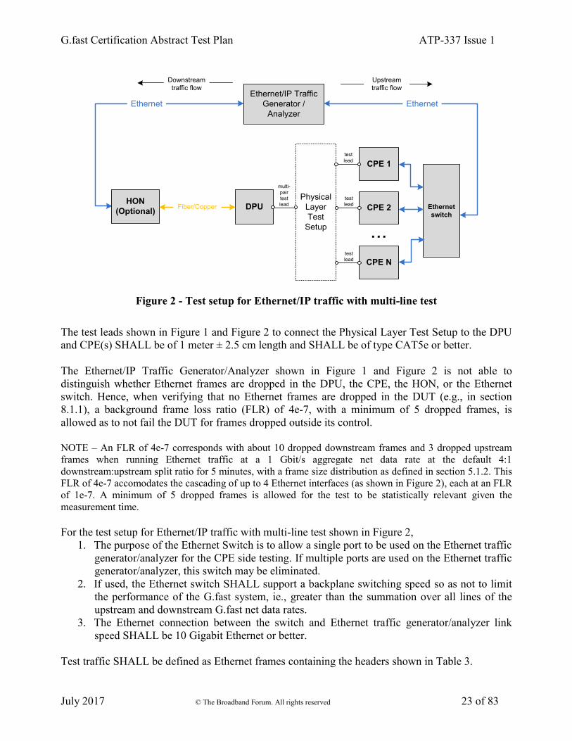
Figure 2 - Test setup for Ethernet/IP traffic with multi-line test
The test leads shown in Figure 1 and Figure 2 to connect the Physical Layer Test Setup to the DPU
and CPE(s) SHALL be of 1 meter ± 2.5 cm length and SHALL be of type CAT5e or better.
The Ethernet/IP Traffic Generator/Analyzer shown in Figure 1 and Figure 2 is not able to
distinguish whether Ethernet frames are dropped in the DPU, the CPE, the HON, or the Ethernet
switch. Hence, when verifying that no Ethernet frames are dropped in the DUT (e.g., in section
8.1.1), a background frame loss ratio (FLR) of 4e-7, with a minimum of 5 dropped frames, is
allowed as to not fail the DUT for frames dropped outside its control.
NOTE – An FLR of 4e-7 corresponds with about 10 dropped downstream frames and 3 dropped upstream
frames when running Ethernet traffic at a 1 Gbit/s aggregate net data rate at the default 4:1
downstream:upstream split ratio for 5 minutes, with a frame size distribution as defined in section 5.1.2. This
FLR of 4e-7 accomodates the cascading of up to 4 Ethernet interfaces (as shown in Figure 2), each at an FLR
of 1e-7. A minimum of 5 dropped frames is allowed for the test to be statistically relevant given the
measurement time.
For the test setup for Ethernet/IP traffic with multi-line test shown in Figure 2,
1. The purpose of the Ethernet Switch is to allow a single port to be used on the Ethernet traffic
generator/analyzer for the CPE side testing. If multiple ports are used on the Ethernet traffic
generator/analyzer, this switch may be eliminated.
2. If used, the Ethernet switch SHALL support a backplane switching speed so as not to limit
the performance of the G.fast system, ie., greater than the summation over all lines of the
upstream and downstream G.fast net data rates.
3. The Ethernet connection between the switch and Ethernet traffic generator/analyzer link
speed SHALL be 10 Gigabit Ethernet or better.
Test traffic SHALL be defined as Ethernet frames containing the headers shown in Table 3.

G.fast Certification Abstract Test Plan ATP-337 Issue 1
July 2017 © The Broadband Forum. All rights reserved 24 of 83
Table 3 - Ethernet/IP test frame definition
Ethernet Frame
Header
VLAN Tag IPv4 Header UDP Header Data Payload
MAC
Destination/Source
Addresses, etc.
Optional,
downstream
flow only
IPv4
Source/Destination
Addresses, etc.
UDP Port, etc. Pseudo-random
bit pattern
The information listed in Table 4 SHALL be used to construct the Ethernet/IP frames used for
testing. Fields not defined SHALL be calculated according to the appropriate standard (e.g.,
RFC791 [7] on IPv4) or SHOULD use well known and/or industry-default values. Frames received
by the CPE LAN interface, for transmission in the upstream direction, SHALL NOT include a
VLAN tag. Frames transmitted in the downstream direction MAY include a VLAN tag, if required
by the HON and/or DPU.
Table 4 - Ethernet/IP frame parameter values
Downstream Flow Upstream Flow Description
Ethernet Frame Header
MAC Destination
Address (Note 1)
MAC1 MAC2 Unicast MAC address, static for the
duration of testing.
MAC Source
Address
MAC2 MAC1
VLAN Tag (Optional)
TPID 0x8100 N/A
VID Based on
equipment
configuration.
N/A
PCP 7 N/A
DEI 0 N/A
IPv4 Header
IP Source IP1 IP3 (Note 2) Unicast IPv4 address. IP1 & IP2
SHOULD be globally routable,
public IP addresses. IP3 MAY be a
private IP address if the CPE is
implementing port forwarding.
IP Destination IP2 (Note 2) IP1
UDP Header
UDP Source Port 1024 1024
UDP Destination
Port
1024 1024
Payload
Datagram Payload PRBS PRBS Pseudo-random bit pattern filling
remainder of frame bytes.

G.fast Certification Abstract Test Plan ATP-337 Issue 1
July 2017 © The Broadband Forum. All rights reserved 25 of 83
NOTE 1 - The destination MAC address might be dependent on the configuration of the CPE.
NOTE 2 - For CPE devices supporting Bridge Mode, IP2 SHALL equal IP3.
5.1.2 Ethernet traffic frame sizes
The following describes the Ethernet traffic and frames sizes which SHALL be used within each
test case described in this document, unless specified otherwise within the specific test case (e.g.,
where a single, fixed frame size is required).
A mix of Ethernet frame sizes SHALL be used during testing, with the mix of frames being evenly
distributed according to the probabilities listed in Table 5.
Table 5 - Frame Size Distribution within Ethernet Traffic
Frame Size (bytes) Probability
1566 0.050
1500 0.673
1024 0.088
256 0.014
64 0.175
NOTE - All Ethernet frame sizes being on the first
byte of the Destination MAC Address and end on
the last byte of the Frame Check Sequence (FCS).
To calculate the total number of frames per second to transmit through a connection of a given bit-
rate, the following calculations SHALL be used.
iiframe
bytes M
i
frame_sizeabilityframe_probf_Mixame_Size_oAverage_Fr1
.
For the Frame Size Distribution in Table 5, the Average_Frame_Size_of_Mix is 1193 bytes.
f_Mixame_Size_oAverage_Fr
8
1hroughputRequired_T
secrame_RateRequired_F
frames,
where Required_Throughput is in units of bits per second, and specified in each specific test case
for a specific direction, upstream or downstream.
5.1.3 Physical Layer Test Setup
This section contains the specifications and information required for building the basic physical
layer testing environment for G.fast test cases defined in this test plan. Different configurations and
settings needed for specific test cases are defined in the related section.

G.fast Certification Abstract Test Plan ATP-337 Issue 1
July 2017 © The Broadband Forum. All rights reserved 26 of 83
One instance of a physical layer test setup is shown in Figure 3, i.e., the instance for the test loop
topology (defined in section 5.4.1) with noise injection. Where the noise is injected (at the DPU-
side or at the CPE-side or at each side of the loop) is specified in each specific test case where noise
injection is part of the test setup. If noise injection is not part of the test setup in a specific test case,
then the High Z injection MAY still be connected to the test loop, but the noise source SHALL be
switched off.
High Z
Noise
Injection
Test Loop Topology
High Z
Noise
Injection
Noise
source
Noise
source
Figure 3 - One instance of a Physical Layer Test Setup
(test loop topology and noise injection)
The requirements for High Impedance (Z) noise injector are specified in section 5.4.3. The
requirements for the cable plant or line simulator are specified in section 5.4.1. The intended
physical layer tests require one noise injection active per direction as there could be a different
noise characteristic for DPU and for CPE.
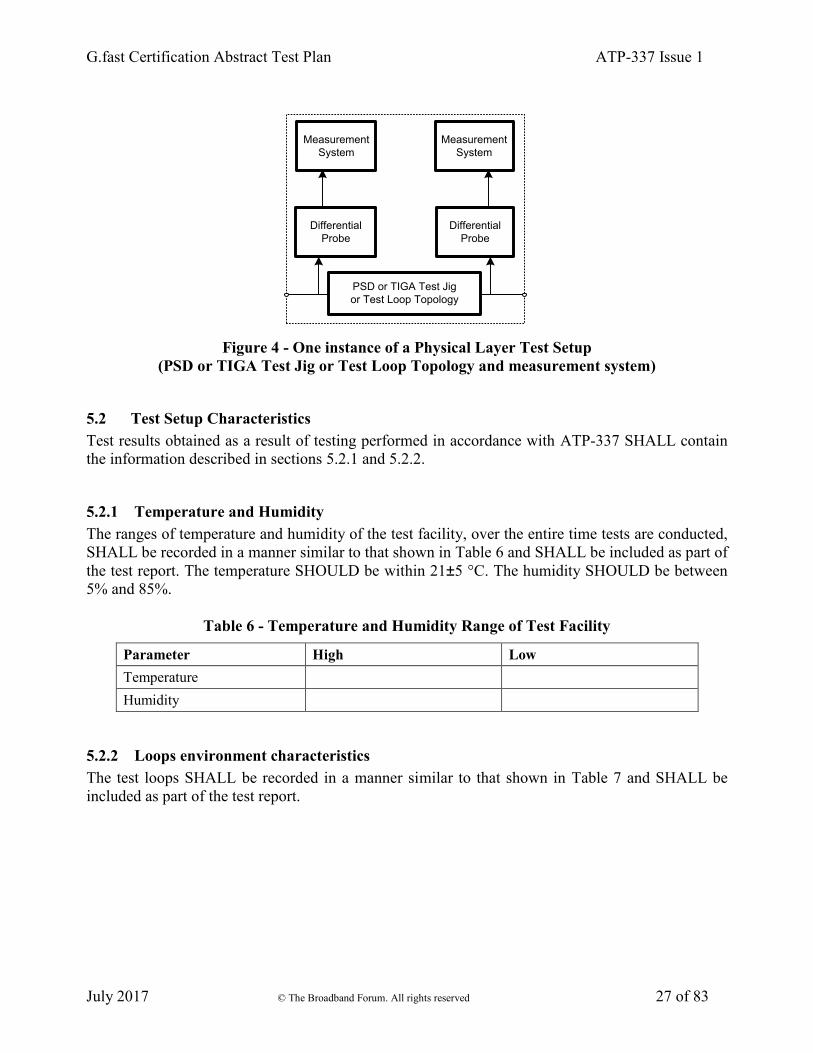
Another instance of a physical layer test setup is shown in Figure 4, i.e., the instance for the PSD
Test Jig (defined in section 5.4.2) or the TIGA Test Jig (defined in section 5.4.3) or the Test Loop
Topology (defined in section 5.4.1) with a measurement system. The measurement point should be
as close as possible to the G.fast interface at the DUT. The measurement system and where it is
connected (at the DPU or at the CPE) is specified in each specific test case where a measurement
system is part of the test setup.
G.fast Certification Abstract Test Plan ATP-337 Issue 1
July 2017 © The Broadband Forum. All rights reserved 27 of 83
Differential
Probe
PSD or TIGA Test Jig
or Test Loop Topology
Differential
Probe
Measurement
System
Measurement
System
Figure 4 - One instance of a Physical Layer Test Setup
(PSD or TIGA Test Jig or Test Loop Topology and measurement system)
5.2 Test Setup Characteristics
Test results obtained as a result of testing performed in accordance with ATP-337 SHALL contain
the information described in sections 5.2.1 and 5.2.2.
5.2.1 Temperature and Humidity
The ranges of temperature and humidity of the test facility, over the entire time tests are conducted,
SHALL be recorded in a manner similar to that shown in Table 6 and SHALL be included as part of
the test report. The temperature SHOULD be within 21±5 °C. The humidity SHOULD be between
5% and 85%.
Table 6 - Temperature and Humidity Range of Test Facility
Parameter High Low
Temperature
Humidity
5.2.2 Loops environment characteristics
The test loops SHALL be recorded in a manner similar to that shown in Table 7 and SHALL be
included as part of the test report.
G.fast Certification Abstract Test Plan ATP-337 Issue 1
July 2017 © The Broadband Forum. All rights reserved 28 of 83
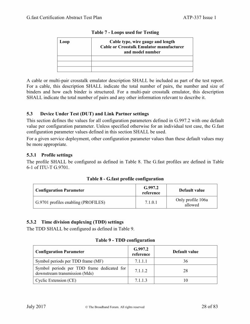
Table 7 - Loops used for Testing
Loop Cable type, wire gauge and length
Cable or Crosstalk Emulator manufacturer
and model number
A cable or multi-pair crosstalk emulator description SHALL be included as part of the test report.
For a cable, this description SHALL indicate the total number of pairs, the number and size of
binders and how each binder is structured. For a multi-pair crosstalk emulator, this description
SHALL indicate the total number of pairs and any other information relevant to describe it.
5.3 Device Under Test (DUT) and Link Partner settings
This section defines the values for all configuration parameters defined in G.997.2 with one default
value per configuration parameter. Unless specified otherwise for an individual test case, the G.fast
configuration parameter values defined in this section SHALL be used.
For a given service deployment, other configuration parameter values than these default values may
be more appropriate.
5.3.1 Profile settings
The profile SHALL be configured as defined in Table 8. The G.fast profiles are defined in Table
6-1 of ITU-T G.9701.
Table 8 - G.fast profile configuration
Configuration Parameter G.997.2
reference Default value
G.9701 profiles enabling (PROFILES) 7.1.0.1 Only profile 106a
allowed
5.3.2 Time division duplexing (TDD) settings
The TDD SHALL be configured as defined in Table 9.
Table 9 - TDD configuration
Configuration Parameter G.997.2
reference Default value
Symbol periods per TDD frame (MF) 7.1.1.1 36
Symbol periods per TDD frame dedicated for
downstream transmission (Mds) 7.1.1.2 28
Cyclic Extension (CE) 7.1.1.3 10

G.fast Certification Abstract Test Plan ATP-337 Issue 1
July 2017 © The Broadband Forum. All rights reserved 29 of 83
5.3.3 Power and spectrum usage settings
The power spectrum usage SHALL be configured as defined in Table 10.
Table 10 - Power spectrum usage configuration
Configuration Parameter G.997.2
reference Default value
Downstream maximum aggregate transmit power
(MAXATPds) 7.1.2.1 4 dBm
Upstream maximum aggregate transmit power
(MAXATPus) 7.1.2.2 4 dBm
Downstream sub-carrier masking (CARMASKds) 7.1.2.3 No masked sub-carriers
Upstream sub-carrier masking (CARMASKus) 7.1.2.4 No masked sub-carriers
Downstream PSD mask (MIBPSDMASKds) 7.1.2.5 Limit PSD mask
defined in G.9700
Upstream PSD mask (MIBPSDMASKus) 7.1.2.6 Limit PSD mask
defined in G.9700
RFI bands (RFIBANDS) 7.1.2.7 No RFI bands
(no PSD reduction)
International Amateur Radio bands (IARBANDS) 7.1.2.8 All IAR bands disabled
(no PSD reduction)
Upstream power back-off reference PSD
(UPBOPSDA) 7.1.2.9
40 dBm/Hz
(Note 1)
Upstream power back-off reference PSD
(UPBOPSDB) 7.1.2.10
0 dBm/Hz
(Note 1)
Upstream electrical length (UPBOKL) 7.1.2.11 0 dB
Force electrical length (UPBOKLF) 7.1.2.12 false (not forced)
UPBO reference electrical length per band
(UPBOKLREF) 7.1.2.13 0 (special value)
NOTE 1 - These values imply that UPBO is disabled.
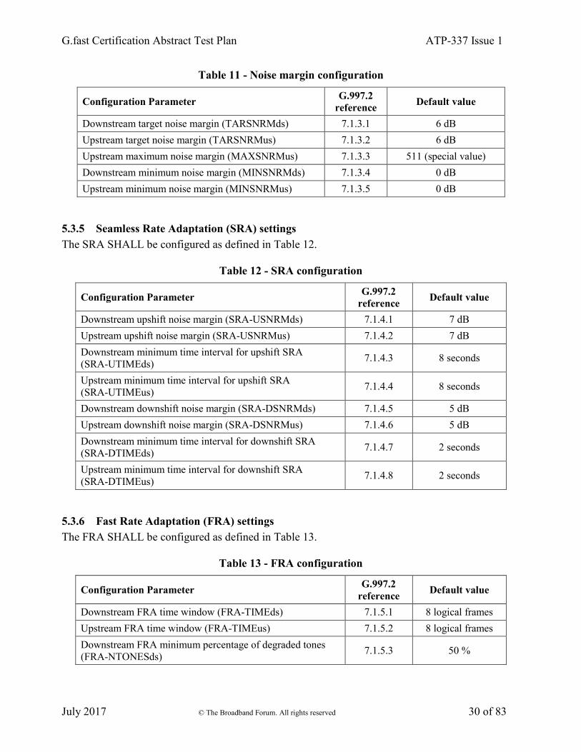
5.3.4 Noise margin (SNRM) settings
The noise margins SHALL be configured as defined in Table 11.
G.fast Certification Abstract Test Plan ATP-337 Issue 1
July 2017 © The Broadband Forum. All rights reserved 30 of 83
Table 11 - Noise margin configuration
Configuration Parameter G.997.2
reference Default value
Downstream target noise margin (TARSNRMds) 7.1.3.1 6 dB
Upstream target noise margin (TARSNRMus) 7.1.3.2 6 dB
Upstream maximum noise margin (MAXSNRMus) 7.1.3.3 511 (special value)
Downstream minimum noise margin (MINSNRMds) 7.1.3.4 0 dB
Upstream minimum noise margin (MINSNRMus) 7.1.3.5 0 dB
5.3.5 Seamless Rate Adaptation (SRA) settings
The SRA SHALL be configured as defined in Table 12.
Table 12 - SRA configuration
Configuration Parameter G.997.2
reference Default value
Downstream upshift noise margin (SRA-USNRMds) 7.1.4.1 7 dB
Upstream upshift noise margin (SRA-USNRMus) 7.1.4.2 7 dB
Downstream minimum time interval for upshift SRA
(SRA-UTIMEds) 7.1.4.3 8 seconds
Upstream minimum time interval for upshift SRA
(SRA-UTIMEus) 7.1.4.4 8 seconds
Downstream downshift noise margin (SRA-DSNRMds) 7.1.4.5 5 dB
Upstream downshift noise margin (SRA-DSNRMus) 7.1.4.6 5 dB
Downstream minimum time interval for downshift SRA
(SRA-DTIMEds) 7.1.4.7 2 seconds
Upstream minimum time interval for downshift SRA
(SRA-DTIMEus) 7.1.4.8 2 seconds
5.3.6 Fast Rate Adaptation (FRA) settings
The FRA SHALL be configured as defined in Table 13.
Table 13 - FRA configuration
Configuration Parameter G.997.2
reference Default value
Downstream FRA time window (FRA-TIMEds) 7.1.5.1 8 logical frames
Upstream FRA time window (FRA-TIMEus) 7.1.5.2 8 logical frames
Downstream FRA minimum percentage of degraded tones
(FRA-NTONESds) 7.1.5.3 50 %

G.fast Certification Abstract Test Plan ATP-337 Issue 1
July 2017 © The Broadband Forum. All rights reserved 31 of 83
Upstream FRA minimum percentage of degraded tones
(FRA-NTONESus) 7.1.5.4 50 %
Downstream FRA number of uncorrectable DTU
(FRA-RTXUCds) 7.1.5.5 150
Upstream FRA number of uncorrectable DTU
(FRA-RTXUCus) 7.1.5.6 150
Downstream vendor discretionary FRA triggering criteria
(FRA-VENDISCds) 7.1.5.7 false (disabled)
Upstream vendor discretionary FRA triggering criteria
(FRA-VENDISCus) 7.1.5.8 false (disabled)
5.3.7 Robust Management Channel (RMC) settings
The RMC SHALL be configured as defined in Table 14.
Table 14 - RMC configuration
Configuration Parameter G.997.2
reference Default value
Downstream target noise margin for RMC
(TARSNRM-RMCds) 7.1.6.1 9 dB
Upstream target noise margin (TARSNRM-RMCus) 7.1.6.2 9 dB
Downstream minimum noise margin for RMC
(MINSNRM-RMCds) 7.1.6.3 3 dB
Upstream minimum noise margin for RMC
(MINSNRM-RMCus) 7.1.6.4 3 dB
Downstream maximum bit loading for RMC
(MAXBL-RMCds) 7.1.6.5 6 bits
Upstream maximum bit loading for RMC (MAXBL-RMCus) 7.1.6.6 6 bits
5.3.8 Vectoring settings
If the DUT or Link Partner is a multi-port DPU, then the vectoring SHALL be configured as
defined in Table 15.
Table 15 - Vectoring configuration for multi-port DPU
Configuration Parameter G.997.2
reference Default value
FEXT cancellation enabling/disabling downstream
(FEXT_TO_CANCEL_ENABLEds) 7.1.7.1 true (enabled)
FEXT cancellation enabling/disabling upstream
(FEXT_TO_CANCEL_ENABLEus) 7.1.7.2 true (enabled)

G.fast Certification Abstract Test Plan ATP-337 Issue 1
July 2017 © The Broadband Forum. All rights reserved 32 of 83
5.3.9 Re-initilaization policy settings
The re-initialization policy SHALL be configured as defined in Table 16.
Table 16 - Re-initialization policy configuration
Configuration Parameter G.997.2
reference Default value
Downstream los defect persistency (LOS_PERSISTENCYds) 7.1.8.1 0.2 seconds
Upstream los defect persistency (LOS_PERSISTENCYus) 7.1.8.2 0.2 seconds
Downstream lom defect persistency
(LOM_PERSISTENCYds) 7.1.8.3 2 seconds
Upstream lom defect persistency (LOM_PERSISTENCYus) 7.1.8.4 2 seconds
Downstream lor defect persistency
(LOR_PERSISTENCYds) 7.1.8.5 0.2 seconds
Upstream lor defect persistency (LOR_PERSISTENCYus) 7.1.8.6 0.2 seconds
Downstream re-initialization time threshold
(REINIT_TIME_THRESHOLDds) 7.1.8.7 10 seconds
Upstream re-initialization time threshold
(REINIT_TIME_THRESHOLDus) 7.1.8.8 10 seconds
Downstream low ETR threshold
(LOW_ETR_THRESHOLDds) 7.1.8.9 20 seconds
Upstream low ETR threshold (LOW_ETR_THRESHOLDus) 7.1.8.10 20 seconds
5.3.10 Update of test parameters settings
The update of test parameters settings SHALL be configured as defined in Table 17.
Table 17 - Update of test parameters configuration
Configuration Parameter G.997.2
reference Default value
Update request flag for near-end test parameters
(UPDATE-NE-TEST) 7.1.9.1
false
(no update forced)
Update request flag for far-end test parameters
(UPDATE-FE-TEST) 7.1.9.2
false
(no update forced)
5.3.11 Data rates settings
The data rates settings for the downstream channel and the data rates settings for the upstream
channel SHALL be configured as defined in Table 18.

G.fast Certification Abstract Test Plan ATP-337 Issue 1
July 2017 © The Broadband Forum. All rights reserved 33 of 83
Table 18 - Downstream and upstream channel data rates configuration
Configuration Parameter G.997.2
reference Default value
Maximum Net Data Rate (MAXNDR) 7.2.1.1 1 500 000 kbit/s
Minimum Expected Throughput (MINETR) 7.2.1.2 518 kbit/s
Maximum Gamma Data Rate (MAXGDR) 7.2.1.3 1 500 000 kbit/s
Minimum Gamma Data Rate (MINGDR) 7.2.1.4 518 kbit/s
5.3.12 Retransmission settings
The downstream retransmission settings and the upstream retransmission settings SHALL be
configured as defined in Table 19.
Table 19 - Downstream and upstream retransmission configuration
Configuration Parameter G.997.2
reference Default value
Maximum delay (DELAYMAX) 7.2.2.1 10 msec
Minimum impulse noise protection against SHINE
(INPMIN_SHINE) 7.2.2.2 0 symbol periods
SHINE ratio (SHINERATIO) 7.2.2.3 0 %
Minimum impulse noise protection against REIN
(INPMIN_REIN) 7.2.2.4 0 symbol periods
REIN Inter-arrival time (IAT_REIN) 7.2.2.5 100 Hz
Minimum Reed-Solomon RFEC/NFEC ratio (RNRATIO) 7.2.2.6 0
RTX-TC testmode (RTX_TESTMODE) 7.2.2.7 false (disabled)
5.3.13 Data path settings
The data path settings SHALL be configured as defined in Table 20.
Table 20 - Data path configuration
Configuration Parameter G.997.2
reference Default value
TPS-TC testmode (TPS_TESTMODE) 7.3.1 false (disabled)
DRA testmode (DRA_TESTMODE) 7.3.2 false (disabled)

G.fast Certification Abstract Test Plan ATP-337 Issue 1
July 2017 © The Broadband Forum. All rights reserved 34 of 83
5.4 Test Setup
5.4.1 Test Loop Topologies
The end-to-end network which extends from the DPU to the CPE includes the following segments:
1) Patch, 2) Multi-Pair Cable, 3) Isolated Drop Wire, 4) Network Termination Point (NTP), and 5)
In Premises Wiring. For the convenience of test setups, this end-to-end network SHALL be
partitioned into 2 separate topologies: the Multi-Pair Cable Test Loop Topology and the Home
Network Bridged Tap Test Loop Topology.
5.4.1.1 Multi-Pair Cable Test Loop Topology
The Multi-Pair Cable Test Loop Topology is shown in Figure 5. This topology is partitioned into
two parts, i.e., the Patch and the Multi-Pair Cable. The Patch is the wiring of the loop that
physically resides at the DP. For the purpose of this test plan, the Patch SHALL be a direct pass
through (i.e., the Patch length SHALL be set to 0 meter). The Multi-Pair Cable SHALL be real
cable or simulated cable.
The test setup of any Multi-Line test case is accommodated by this topology with an appropriate
choice of Multi-Pair cable length(s).
Single-Line test cases SHALL use a single pair from the Multi-Pair Cable. All unused pairs SHALL
be terminated at both sides of the loop with an 100 Ohm reference load.
DPU
CPE 1
test
lead
CPE 2
test
lead
CPE 3
test
lead
CPE 4
test
lead
CPE 5
test
lead
CPE 6
test
lead
CPE 7
test
lead
CPE 8
test
lead
test
lead
test
lead
test
lead
test
lead
test
lead
test
lead
test
lead
test
lead
Patch
0 m
Multi-Pair Cable
CAD55/CW1420
20, 50, 100, 200, 400 m
Figure 5 - Multi-Pair Cable Test Loop Topology
Test leads to connect the Multi-Pair Cable to the DUT and link partner (see also Figure 1 and Figure
2) SHALL be 1 meter in length and SHALL be of type CAT5e or better. At DPU side, the test leads
MAY share the same cable, with crosstalk between the test leads. At CPE side, isolation between
the test leads SHALL be as defined in section 5.4.5.6.
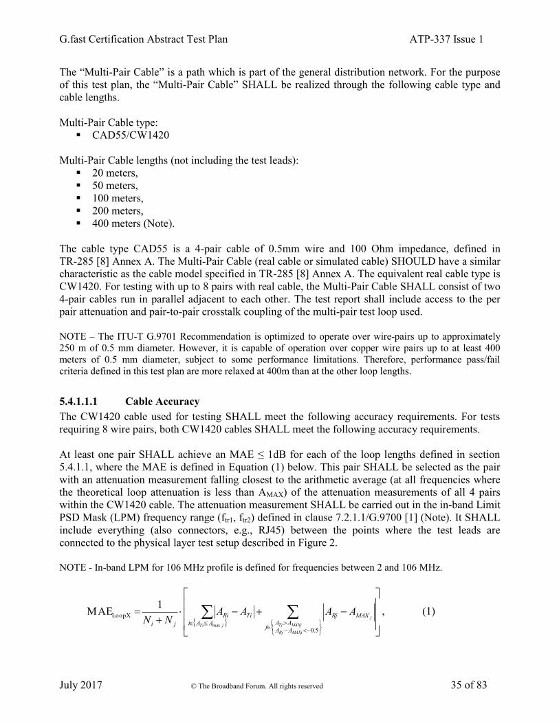
G.fast Certification Abstract Test Plan ATP-337 Issue 1
July 2017 © The Broadband Forum. All rights reserved 35 of 83
The “Multi-Pair Cable” is a path which is part of the general distribution network. For the purpose
of this test plan, the “Multi-Pair Cable” SHALL be realized through the following cable type and
cable lengths.
Multi-Pair Cable type:
CAD55/CW1420
Multi-Pair Cable lengths (not including the test leads):
20 meters,
50 meters,
100 meters,
200 meters,
400 meters (Note).
The cable type CAD55 is a 4-pair cable of 0.5mm wire and 100 Ohm impedance, defined in
TR-285 [8] Annex A. The Multi-Pair Cable (real cable or simulated cable) SHOULD have a similar
characteristic as the cable model specified in TR-285 [8] Annex A. The equivalent real cable type is
CW1420. For testing with up to 8 pairs with real cable, the Multi-Pair Cable SHALL consist of two
4-pair cables run in parallel adjacent to each other. The test report shall include access to the per
pair attenuation and pair-to-pair crosstalk coupling of the multi-pair test loop used.
NOTE – The ITU-T G.9701 Recommendation is optimized to operate over wire-pairs up to approximately
250 m of 0.5 mm diameter. However, it is capable of operation over copper wire pairs up to at least 400
meters of 0.5 mm diameter, subject to some performance limitations. Therefore, performance pass/fail
criteria defined in this test plan are more relaxed at 400m than at the other loop lengths.
5.4.1.1.1 Cable Accuracy
The CW1420 cable used for testing SHALL meet the following accuracy requirements. For tests
requiring 8 wire pairs, both CW1420 cables SHALL meet the following accuracy requirements.
At least one pair SHALL achieve an MAE ≤ 1dB for each of the loop lengths defined in section
5.4.1.1, where the MAE is defined in Equation (1) below. This pair SHALL be selected as the pair
with an attenuation measurement falling closest to the arithmetic average (at all frequencies where
the theoretical loop attenuation is less than AMAX) of the attenuation measurements of all 4 pairs
within the CW1420 cable. The attenuation measurement SHALL be carried out in the in-band Limit
PSD Mask (LPM) frequency range (ftr1, ftr2) defined in clause 7.2.1.1/G.9700 [1] (Note). It SHALL
include everything (also connectors, e.g., RJ45) between the points where the test leads are
connected to the physical layer test setup described in Figure 2.
NOTE - In-band LPM for 106 MHz profile is defined for frequencies between 2 and 106 MHz.
5.0
XLoop
max
1MAE
MAXjRj
MAXjTj
j
jTi
AA
AAj
MAXRj
AAi
TiRi
ji
AAAANN
, (1)
G.fast Certification Abstract Test Plan ATP-337 Issue 1
July 2017 © The Broadband Forum. All rights reserved 36 of 83
where
ARi = Attenuation sample, in dB, of the measured loop X,
ATi = Attenuation sample, in dB, of the theoretical loop X, and
AMAX SHALL be equal to 70dB.
The ATi values SHALL be calculated according to the models defined in TR-285.
The index “i” belongs to a set defined by the points necessary to measure the attenuation in steps of
50kHz or less and taking into account only those measurement points for which AT ≤ AMAX dB.
Ni is the number of elements in the above set.
The index “j” belongs to a set defined by the points necessary to measure the attenuation in steps of
50kHz or less and taking into account only those measurement points for which AT > AMAX dB and
AR – AMAX < -0.5 dB.
Nj is the number of elements in the above set.
Due to the construction of the CW1420, it is expected the other pairs SHOULD have MAEs
satisfying the following requirements for each of the loop lengths defined in section 5.4.1.1:
1) At least 2 of the 3 remaining pairs will have an MAE ≤ 5 dB.
2) The final remaining pair will have an MAE ≤ 10 dB.
All single pair testing defined within this test plan SHALL use the pair identified with an MAE ≤ 1
dB within the CW1420 cable, which SHALL meet the above accuracy requirements. Additionally,
care SHOULD be taken in the construction of any physical cable plant to minimize the impacts of
cross-talk between cables or loop lengths, which might negatively impact the operation of G.fast
systems under test.
5.4.1.2 Home Network Bridged Tap Test Loop Topology
The Home Network Bridged Tap (HNBT) Test Loop Topology is shown in Figure 6. This topology
is partitioned into two parts, i.e., the Isolated Drop Wire and the In Premises Wiring, separated by
the Network Termination Point (NTP reference point). The In Premises Wiring topology SHALL be
a star configuration consisting of 4 bridged taps and one branch to the CPE, all connected at the
NTP.

G.fast Certification Abstract Test Plan ATP-337 Issue 1
July 2017 © The Broadband Forum. All rights reserved 37 of 83
DPU CPE
test
leadtest
lead
Isolated Drop Wire
CAD55/CW1420In Premises Wiring
CAD55/CW1420
20 m
2 m
2.5 m
5 m
10 m
100 m
NTP reference point
Figure 6 - Home Network Bridged Tap Test Loop Topology
Test leads to connect the test loop to the DUT and link partner (see also Figure 1 and Figure 2)
SHALL be 1 meter in length and SHALL be of type CAT5e or better.
The “Isolated Drop Wire” (see Figure 6) represents the individual subscriber drop wires. For the
purpose of this test plan, the “Isolated Drop Wire” SHALL be realized by using a single pair within
the following cable type and cable lengths.
Isolated Drop Wire Cable Type:
CAD55/CW1420
Isolated Drop Wire Cable length (not including the test lead):
100 meters
Any unused pairs within the cable SHALL be terminated with 100 Ohm reference impedances.
For the purpose of this test plan, the “In Premises Wiring” SHALL be realized using a single pair
within the following cable type and cable lengths.
In Premises Wiring Cable Type:
CAD55/CW1420
Bridged Tap Lengths from the NTP:
2 meters
2.5 meters
5 meters
10 meters
CPE Branch Length from the NTP (not including the test lead):
20 meters
Any unused pairs within the cable SHALL be terminated with 100 Ohm reference impedances.
Each bridged tap SHALL be unterminated. The crosstalk isolation between any of bridged taps and
between any bridged tap and the branch to the CPE SHALL be as defined in section 5.4.5.6.

G.fast Certification Abstract Test Plan ATP-337 Issue 1
July 2017 © The Broadband Forum. All rights reserved 38 of 83
5.4.2 PSD Test Jig
The PSD Test Jig is shown in Figure 7. The PSD Test Jig is a flat attenuator that allows the DUT to
transmit at its full power (no power back off) and has the advantage of being very well matched to
the design impedance, which limits the reflection of power into the measurement.
DPU CPE
test
leada
PSD Test Jig
100 Ω flat attenuator
PSD
measurement
point
PSD
measurement
point
b
test
lead
Figure 7 - PSD Test Jig
Test leads to connect the PSD Test Jig to the DUT and link partner (see also Figure 1 and Figure 2)
SHALL be 1 meter ± 2.5 cm in length and SHALL be of type CAT5e or better.
The PSD Test Jig SHALL have the following characteristics at the terminals a and b (see Figure 7).
The test report shall include access to the attenuation of the PSD Test Jig used.
5.4.2.1 Input impedance
At both terminals a and b, the input impedance SHALL be equal to 100 Ohms ± 1% for all
frequencies from 138 kHz to 120 MHz.
The input impedance at a given terminal SHALL be measured with an 100 Ohm reference load
impedance at the other terminal.
5.4.2.2 Voltage Transfer Function
For each direction a→b and b→a, the voltage transfer function (VTF) SHALL be between
VTF_MIN = -20dB and VTF_MAX = -17dB for all frequencies from 138 kHz to 120 MHz.
The VTF SHALL be measured with an 100 Ohm reference source impedance at the transmit
terminal and an 100 Ohm reference load impedance at the other terminal.
5.4.3 TIGA Test Jig
The TIGA Test Jig is shown in Figure 8 for the downstream direction. The TIGA Test Jig and
measurement point are reversed for the upstream direction. The TIGA Test Jig allows the DUT to
transmit at its full power (no power back off) and has the advantage of being well matched to the
design impedance, which limits the reflection of power into the measurement. The TIGA Test Jig

G.fast Certification Abstract Test Plan ATP-337 Issue 1
July 2017 © The Broadband Forum. All rights reserved 39 of 83
also allows insertion of FEXT at a level that triggers the Transmitter Initiated Gain Adjustment
(TIGA) functionality (see section 6.2.5).
DPU
CPE 1
test
lead
CPE 2
test
lead
CPE 3
test
lead
CPE 4
test
lead
test
lead
test
lead
test
lead
test
lead
Line #1
Line #2
Line #3
Line #4
High crosstalk from
Lines #2-3-4 into Line #1
TIGA Test Jig
100 Ω attenuator
PSD measurement point
1a
2a
3a
4a
1b
2b
3b
4b
Figure 8 - TIGA Test Jig for the downstream direction
Test leads to connect the TIGA Test Jig to the DUT and link partner (see also Figure 1 and Figure
2) SHALL be 1 meter ± 2.5 cm in length and SHALL be of type CAT5e or better. At DPU side, the
test leads MAY share the same cable, with crosstalk between the test leads. At CPE side, isolation
between the test leads SHALL be as defined in section 5.4.5.6.
The TIGA Test Jig characteristics SHALL have the following characteristics amongst the 8
terminals 1a/2a/3a/4a and 1b/2b/3b/4b (see Figure 8). The test report shall include access to the
attenuation and pair-to-pair crosstalk coupling of the TIGA Test Jig used.
5.4.3.1 Input impedance
At each terminal [n]a and [n]b (with [n]=1 to 4), the input impedance (with the other terminals
terminated with an 100 Ohm reference load) SHALL be equal to 100 Ohms ± 10% for all
frequencies from 138 kHz to 120 MHz.
The input impedance at a given terminal SHALL be measured with an 100 Ohm reference load
impedance at all other terminals.
NOTE 1 - The input impedance tolerance of the TIGA Test Jig is taken into account for G.9700 PSD Limit
Mask verification by allowing for a tolerance of 1dB above the PSD Limit Mask specified in G.9700 (see
section 6.2.6.7).
NOTE 2 - The TIGA Test Jig cannot be used for the Transmit PSD verification tests defined in sections 6.2.1
to 6.2.5. A PSD Test Jig is defined for that purpose in section 5.4.2.
5.4.3.2 Direct path VTF
For each direction [n]a→[n]b and [n]b→[n]a (with [n]=1 to 4), the direct path voltage transfer
function (VTF) SHALL be higher than the VTF_MIN and lower than the VTF_MAX defined in
Table 21.
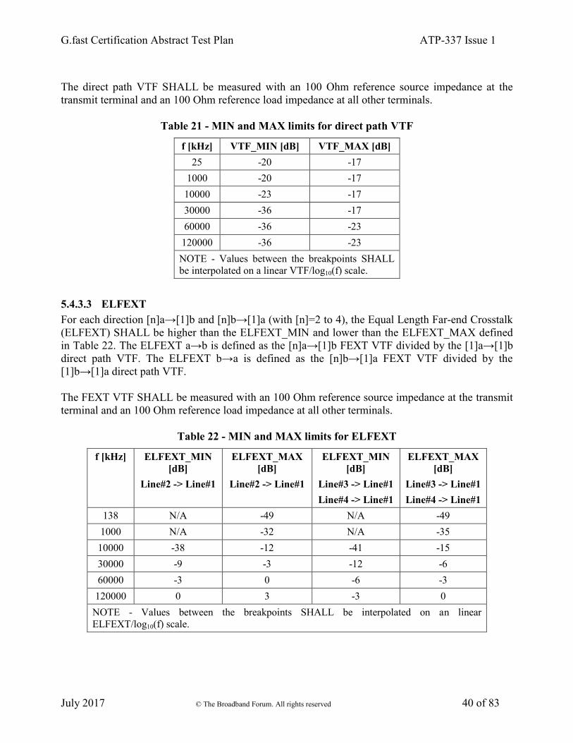
G.fast Certification Abstract Test Plan ATP-337 Issue 1
July 2017 © The Broadband Forum. All rights reserved 40 of 83
The direct path VTF SHALL be measured with an 100 Ohm reference source impedance at the
transmit terminal and an 100 Ohm reference load impedance at all other terminals.
Table 21 - MIN and MAX limits for direct path VTF
f [kHz] VTF_MIN [dB] VTF_MAX [dB]
25 -20 -17
1000 -20 -17
10000 -23 -17
30000 -36 -17
60000 -36 -23
120000 -36 -23
NOTE - Values between the breakpoints SHALL
be interpolated on a linear VTF/log10(f) scale.
5.4.3.3 ELFEXT
For each direction [n]a→[1]b and [n]b→[1]a (with [n]=2 to 4), the Equal Length Far-end Crosstalk
(ELFEXT) SHALL be higher than the ELFEXT_MIN and lower than the ELFEXT_MAX defined
in Table 22. The ELFEXT a→b is defined as the [n]a→[1]b FEXT VTF divided by the [1]a→[1]b
direct path VTF. The ELFEXT b→a is defined as the [n]b→[1]a FEXT VTF divided by the
[1]b→[1]a direct path VTF.
The FEXT VTF SHALL be measured with an 100 Ohm reference source impedance at the transmit
terminal and an 100 Ohm reference load impedance at all other terminals.
Table 22 - MIN and MAX limits for ELFEXT
f [kHz] ELFEXT_MIN
[dB]
Line#2 -> Line#1
ELFEXT_MAX
[dB]
Line#2 -> Line#1
ELFEXT_MIN
[dB]
Line#3 -> Line#1
Line#4 -> Line#1
ELFEXT_MAX
[dB]
Line#3 -> Line#1
Line#4 -> Line#1
138 N/A -49 N/A -49
1000 N/A -32 N/A -35
10000 -38 -12 -41 -15
30000 -9 -3 -12 -6
60000 -3 0 -6 -3
120000 0 3 -3 0
NOTE - Values between the breakpoints SHALL be interpolated on an linear
ELFEXT/log10(f) scale.

G.fast Certification Abstract Test Plan ATP-337 Issue 1
July 2017 © The Broadband Forum. All rights reserved 41 of 83
5.4.3.4 NEXT VTF
For each terminal pair [n]a→[1]a (with [n]= 2 to 4), the NEXT VTF SHALL be lower than -30dB.
The NEXT VTF SHALL be measured with an 100 Ohm reference source impedance at the transmit
terminal and an 100 Ohm reference load impedance at all other terminals.
5.4.4 Noise Models
5.4.4.1 Stationary Noise
5.4.4.1.1 Flat Noise
Flat Noise is defined as Additive Gaussian White Noise (AWGN) that extends from 138 kHz to
120 MHz.
NOTE – The AWGN extends to 120 MHz so that it is not discontinuous at the 106 MHz boundary of the
G.9700/G.9701 signal spectrum.
The Flat Noise PSD levels are defined in the test setup section of the specific tests using Flat Noise.
Over the 138 kHz to 120 MHz frequency range, the Mean Absolute Error (MAE, see section
5.4.6.1) of the Flat Noise SHALL be less than or equal to 0.5 dB.
5.4.4.1.2 Band-limited Noise
Band-limited Noise is defined as Additive Gaussian Noise (AGN) that extends from 2 MHz to
120 MHz with a PSD as defined in this section.
NOTE – The AGN extends to 120 MHz so that it is not discontinuous at the 106 MHz boundary of the
G.9700/G.9701 signal spectrum.
Six Band-limited Noises are defined (referred to as BLN-Type1 to BLN-Type6, see Figure 9 and
Figure 10).
For Band-limited Noise of Type 1, the PSD (referred to as PSDBLN1) is defined as follows:
PSDBLN1 = -140 dBm/Hz for 2 MHz ≤ f ≤ 50 MHz
-115 dBm/Hz for 50 MHz <f ≤ 60 MHz (noise band 1)
-140 dBm/Hz for 60 MHz < f ≤ 70 MHz
-125 dBm/Hz for 70 MHz <f ≤ 80 MHz (noise band 2)
-140 dBm/Hz for 80 MHz < f ≤ 120 MHz
For Band-limited Noise of Type 2, the PSD (referred to as PSDBLN2) is defined as follows:
PSDBLN2 = -140 dBm/Hz for 2 MHz ≤ f ≤ 50 MHz
-125 dBm/Hz for 50 MHz <f ≤ 60 MHz (noise band 1)
-140 dBm/Hz for 60 MHz < f ≤ 70 MHz
-115 dBm/Hz for 70 MHz <f ≤ 80 MHz (noise band 2)
-140 dBm/Hz for 80 MHz < f ≤ 120 MHz

G.fast Certification Abstract Test Plan ATP-337 Issue 1
July 2017 © The Broadband Forum. All rights reserved 42 of 83
For Band-limited Noise of Type 3, the PSD (referred to as PSDBLN_RPA_1) is defined as follows:
PSDBLN_RPA_1 = -115 dBm/Hz for 2 MHz ≤ f ≤ 28 MHz
-140 dBm/Hz for 28 MHz <f ≤ 120 MHz (RPA noise band 1)
For Band-limited Noise of Type 4, the PSD (referred to as PSDBLN_RPA_2) is defined as follows:
PSDBLN_RPA_2 = -140 dBm/Hz for 2 MHz ≤ f ≤ 28 MHz
-115 dBm/Hz for 28 MHz <f ≤ 54 MHz (RPA noise band 2)
-140 dBm/Hz for 54 MHz ≤ f ≤ 120 MHz
For Band-limited Noise of Type 5, the PSD (referred to as PSDBLN_RPA_3) is defined as follows:
PSDBLN_RPA_3 = -140 dBm/Hz for 2 MHz ≤ f ≤ 54 MHz
-115 dBm/Hz for 54 MHz <f ≤ 80 MHz (RPA noise band 3)
-140 dBm/Hz for 80 MHz ≤ f ≤ 120 MHz
For Band-limited Noise of Type 6, the PSD (referred to as PSDBLN_RPA_4) is defined as follows:
PSDBLN_RPA_4 = -140 dBm/Hz for 2 MHz ≤ f ≤ 80 MHz
-115 dBm/Hz for 80 MHz <f ≤ 120 MHz (RPA noise band 4)
Over the 2 MHz to 120 MHz frequency range (excluding a 500 kHz guard band centered around the
noise step frequencies), the Mean Absolute Error (MAE, see section 5.4.6.1) of the Band-limited
Noise SHALL be less than or equal to 0.5 dB.
Figure 9 - PSD of the Band-limited Noise of Type 1 and 2.
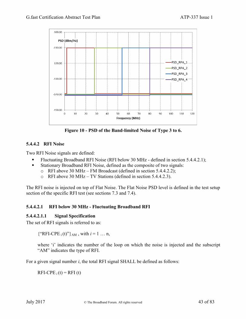
G.fast Certification Abstract Test Plan ATP-337 Issue 1
July 2017 © The Broadband Forum. All rights reserved 43 of 83
Figure 10 - PSD of the Band-limited Noise of Type 3 to 6.
5.4.4.2 RFI Noise
Two RFI Noise signals are defined:
Fluctuating Broadband RFI Noise (RFI below 30 MHz - defined in section 5.4.4.2.1);
Stationary Broadband RFI Noise, defined as the composite of two signals:
o RFI above 30 MHz – FM Broadcast (defined in section 5.4.4.2.2);
o RFI above 30 MHz – TV Stations (defined in section 5.4.4.2.3).
The RFI noise is injected on top of Flat Noise. The Flat Noise PSD level is defined in the test setup
section of the specific RFI test (see sections 7.3 and 7.4).
5.4.4.2.1 RFI below 30 MHz - Fluctuating Broadband RFI
5.4.4.2.1.1 Signal Specification
The set of RFI signals is referred to as:
{“RFI-CPE i (t)”}AM , with i = 1 … n,
where ‘i’ indicates the number of the loop on which the noise is injected and the subscript
“AM” indicates the type of RFI.
For a given signal number i, the total RFI signal SHALL be defined as follows:
RFI-CPE i (t) = RFI (t)

G.fast Certification Abstract Test Plan ATP-337 Issue 1
July 2017 © The Broadband Forum. All rights reserved 44 of 83
The signal set {“RFI-CPE i (t)”}AM SHALL be injected in differential mode. When injected on more
than one loop, the signal set {“RFI-CPE i (t)”}AM SHALL be correlated (see section 5.4.5.5).
The Baseline Total RFI Signal, RFI(t), SHALL be composed of the 50 modulated RFI tones defined
in Table 23. Of these 50 tones, exactly 45 tones SHALL correspond to RFI interferers which are
AM broadcast interferers. Of these 50 tones, exactly 5 tones SHALL correspond to RFI interferers
which are Amateur Radio interferers.
NOTE - The modulation on these tones is consistent with the Fluctuating Broadband RFI Model defined in
section D.4.6 of TR-114 Issue 2 [4].
The tones representing the AM broadcast interferers SHALL each consist of double side band
modulation. The tones representing the Amateur Radio interferers SHALL each consist of single
side band suppressed carrier modulation (SSB).
Each tone SHALL be independently modulated with speech weighted noise, and is limited to 4.2
kHz, each noise source being independently modulated at the syllabic rate. Speech weighted noise
SHALL be as defined in ITU-T G.227 [6], which is limited to 4.2 kHz. The target modulation index
for each tone is 50%. Syllabic modulation SHALL be performed by periodically interrupting a
continuous speech weighted noise source for a period of 150 ms every 200 ms. In the case of
amateur band SSB signals, the carrier power column data SHOULD be interpreted as the power of
the SSB signal during the on period of the syllabic rated modulation.
The modulating noise SHALL be fluctuating at the syllabic rate and SHALL be subject to fading at
a rate and with a time profile representative of night time reception conditions. The fading between
different carriers in the set SHALL be independent. In order to achieve the appropriate fading, the
dual Arbitrary Waveform Generator (AWG) method specified in section D.4.6 of TR-114 Issue 2
[4] SHALL be used.
NOTE - This AWG method specifies that to achieve a fade of approximately 1000 seconds duration for
carriers in the region of 1 MHz, one of the generators needs to produce a carrier at 1.000000001 MHz. This
can be achieved using reference clocks of 10 MHz and 10.00000001 MHz to 2 AWGs, or by using one
AWG with a pattern length of 256×M samples (where M = 220
) and one with a pattern length of 256×M - 8
samples.
5.4.4.2.1.2 Specifications of Carrier Power
Table 23 defines for each of the 50 RF tones, the frequency, the differential mode carrier power
(into a 50 Ohm reference load), and whether the tone is an Amateur Radio Interferer.

G.fast Certification Abstract Test Plan ATP-337 Issue 1
July 2017 © The Broadband Forum. All rights reserved 45 of 83
Table 23 - Differential Mode Carrier Powers for Total RFI Signal,
RFI (t) - Fluctuating Broadband RFI Case
RF Tone
Number
Carrier
Frequency (fc)
(kHz)
Differential Mode
Carrier Power
(dBm)
Amateur Radio
Interferer
1 99 -58
2 270 -93
3 333 -50
4 531 -59
5 630 -82
6 711 -57
7 801 -62
8 855 -80
9 909 -52
10 999 -63
11 1269 -83
12 3250 -56
13 3330 -71
14 3365 -59
15 3695 -75 Yes
16 3770 -90 Yes
17 4845 -80
18 5035 -93
19 5980 -56
20 6005 -85
21 6050 -85
22 6095 -78
23 6160 -89
24 6180 -63
25 7130 -71 Yes
26 7145 -90 Yes
27 7350 -92
28 9495 -58
29 9620 -74
30 9685 -91
31 9705 -93
32 9820 -82
33 11610 -92
34 11720 -85
35 11810 -82
36 11915 -90
37 12050 -90
38 12185 -59
39 13790 -70
40 14115 -60 Yes
41 15140 -87
42 15385 -87
43 15735 -68
44 17585 -65
45 17625 -77
46 17780 -78
47 21670 -68
48 21690 -92

G.fast Certification Abstract Test Plan ATP-337 Issue 1
July 2017 © The Broadband Forum. All rights reserved 46 of 83
49 21755 -75
50 23960 -86
For each AM Broadcast Interferer, the peak power measured over the modulation band SHALL be
within 0.5 dB of the carrier power defined in Table 23. The modulation band is defined as
[fc - 4.2 kHz, fc + 4.2 kHz].
For each Amateur Radio Interferer, the peak power measured over the modulation band SHALL be
within 0.5 dB of the carrier power defined in Table 23. The modulation band is defined as
[fc , fc + 4.2 kHz].
5.4.4.2.2 RFI Above 30 MHz - FM Broadcast
The FM Broadcast RFI is to be considered as a set of RFI noises injected simultaneously on each
loop. These are to represent multiple broadcast FM carriers.
5.4.4.2.2.1 Signal Specification
The set of RFI signals is referred to as:
{“RFI-CPE i (t)”}FM , with i = 1 … n,
where ‘i’ indicates the number of the loop on which the noise is injected and the subscript “FM”
indicates the type of RFI.
For a given signal number i, the total RFI signal SHALL be defined as follows:
RFI-CPE i (t) = RFI (t).
The signal set {“RFI-CPE i (t)”}FM SHALL be injected in differential mode. When injected on more
than one loop, the signal set {“RFI-CPE i (t)”}FM SHALL be correlated (see section 5.4.5.5).
The Baseline Total RFI Signal, RFI(t), SHALL be composed of the 11 broadcast FM signals
defined in Table 24. Ten (10) of these signals are centered below 100 MHz. The 11th broadcast FM
signal is placed between 100 MHz and 120 MHz. Its purpose is to provide a strong interferer which
is out of band relative to G.9701 operating below 106 MHz.
Each of the FM broadcast interferers in the set SHALL be independently modulated by a
cosinusoidal signal of frequency fm of the form β × cos (2π × fm × t). The parameter β is the
modulation index. The total FM broadcast interferer is then of the following form where fc is the
interferer center frequency:
cos ( 2π × fc × t + β × cos (2π × fm × t) ).
The bandwidth of the FM broadcast interferer is consistent with a 0.2 MHz spacing between
adjacent FM broadcast carrier frequencies. The modulation band is defined as:
[fc – β × fm , fc + β × fm ].

G.fast Certification Abstract Test Plan ATP-337 Issue 1
July 2017 © The Broadband Forum. All rights reserved 47 of 83
5.4.4.2.2.2 Specification of Carrier Power and Signal Structure
Table 24 defines for each of the 11 broadcast FM signals, the signal structure (frequency,
modulation frequency, and modulation index), and the differential mode carrier power (into a 50
Ohm reference load). The modulation frequency and modulation index are chosen so that the
modulation bandwidth is less than 0.2 MHz. For each broadcast FM signal, the average power over
the modulation bandwidth shall be within 0.5 dB of the carrier power defined in Table 24.
Table 24 - Differential Mode Carrier Powers and
Signal Structure for RFI Signal- FM Broadcast
Description Carrier Frequency
(fc) (MHz)
Modulation
Frequency (fm)
(kHz)
Modulation
Index (β)
Differential Mode
Carrier Power
(dBm)
1 88.3 15 5 -63
2 89.1 15 5 -68
3 89.9 15 5 -62
4 90.5 15 5 -66
5 91.3 15 5 -65
6 91.9 15 5 -65
7 92.7 15 5 -67
8 93.5 15 5 -64
9 95.3 15 5 -62
10 99.1 15 5 -60
11 107.9 15 5 -70
5.4.4.2.3 RFI Above 30 MHz - TV Stations
This is to be considered as a set of RFI noises injected simultaneously on each loop. These are to
represent digital TV signals.
5.4.4.2.3.1 Signal Specification
The set of RFI signals is referred to as:
{“RFI-CPE i (t)”}TV , with i = 1 … n,
where ‘i’ indicates the number of the loop on which the noise is injected and the subscript
“TV” indicates the type of RFI.
For a given signal number i, the total RFI signal SHALL be defined as follows:
RFI-CPE i (t) = RFI (t).
The signal set {“RFI-CPE i (t)”}TV SHALL be injected in differential mode. When injected on more
than one loop, the signal set {“RFI-CPE i (t)”}TV SHALL be totally correlated, distributed from the
same source.

G.fast Certification Abstract Test Plan ATP-337 Issue 1
July 2017 © The Broadband Forum. All rights reserved 48 of 83
The Baseline Total RFI Signal, RFI(t), SHALL be composed of the 4 digital TV signals defined in
Table 25.
Each of the TV signal interferers in the set SHALL be independently modulated with Gaussian
Noise which SHALL be flat and SHALL begin 0.31 MHz from the start the modulation band and
SHALL end 0.31 MHz from the end of the modulation band. This allows for a guard band between
adjacent TV channels.
5.4.4.2.3.2 Specification of Carrier Power and Signal Structure
Table 25 defines for each of the 4 digital TV signals, the modulation band and the differential mode
interferer power (into a 50 Ohm reference load). These values take into account common mode to
differential mode conversion.
Table 25 - Differential Mode Carrier Powers and Signal Structure for RFI Signal- TV
Description Modulation
Band
(MHz)
Diferential Mode
Interferer Power
(dBm)
TV Channel 2 54 - 60 -50.0
TV Channel 3 60 - 66 -52.2
TV Channel 4 66 - 72 -52.2
TV Channel 5 76 - 82 -54.0
For each digital TV signal, the average power measured over the modulation band SHALL be
within 0.5 dB of the interferer power defined in Table 25.
5.4.4.3 Impulse Noise
5.4.4.3.1 REIN
REIN is defined as a repetition of an AWGN burst, with the time domain and frequency domain
characteristics defined in following sub-sections.
5.4.4.3.1.1 REIN Time Domain Characteristics
Two types of REIN are defined, with characteristics listed in Table 26.
Table 26 - REIN time domain characteristics
Parameter Type 1 Type 2
burst duration 100s 1ms
burst repetition 10ms (100Hz) 10ms (100Hz)
5.4.4.3.1.2 REIN Frequency Domain Characteristics
During each REIN burst, the REIN PSD is defined as follows (see Figure 11):

G.fast Certification Abstract Test Plan ATP-337 Issue 1
July 2017 © The Broadband Forum. All rights reserved 49 of 83
MHzffforHzdBmff
ffkHzforHzdBmfPSD
CC
C
REIN120,/150,/log4090max
138,/90)(
10
,
with f in Hz and fC = 2.2×10⁶ Hz.
Over the 138 kHz to 40 MHz frequency range, the MAE (see section 5.4.6.1) of the REIN PSD
SHALL be less than or equal to 0.5 dB. NOTE - An MAE up to 40 MHz corresponds with an MAE down to a noise level of about -140 dBm/Hz.
Outside the REIN burst, no REIN noise is generated.
The REIN noise is injected on top of Flat Noise. The Flat Noise PSD level is defined in the test
setup section of the specific REIN test (see section 7.2).
Figure 11 - The PSD of a single REIN burst
5.4.4.3.2 SHINE
SHINE is defined as a repetition of an AGN burst, with the time domain and frequency domain
characteristics defined in following sub-sections.
5.4.4.3.2.1 SHINE Time Domain Characteristics
Three types of SHINE are defined (referred to as Type 1, Type 2, and Type 3), with characteristics
listed in Table 27.
Table 27 - SHINE time domain characteristics
Parameter Type 1 Type 2 Type 3
burst duration 4ms 100ms 800ms
burst repetition 1s 10s 20s

G.fast Certification Abstract Test Plan ATP-337 Issue 1
July 2017 © The Broadband Forum. All rights reserved 50 of 83
5.4.4.3.2.2 SHINE Frequency Domain Characteristics
During each SHINE burst, the SHINE PSD SHALL be as defined for the Flat Noise in 5.4.4.1.1,
with a Flat Noise PSD level of -90 dBm/Hz.
Over the 138 kHz to 120 MHz frequency range, the MAE (see section 5.4.6.1) of the SHINE PSD
SHALL be less than or equal to 0.5 dB.
Outside the SHINE burst, no SHINE noise is generated.
The SHINE noise is injected on top of Flat Noise. The Flat Noise PSD level is defined in the test
setup section of the specific SHINE test (see section 7.1).
5.4.5 Noise injection
5.4.5.1 Bandwidth
The noise injector SHALL be capable of injecting Noise/Interference profiles with PSDs included
in the spectral range extending from 138 kHz to 120 MHz for testing G.fast 106 MHz profile.
5.4.5.2 Simultaneous Noise/Interference Multi-line Injection
The noise injector SHALL allow simultaneous injection on N lines, where 1 ≤N ≤8, depending
upon the specific test case.
5.4.5.3 Modes of Injection
Noise injection on each line SHALL be by Differential Mode.
5.4.5.4 Impedance
With the noise/interference considered as a current source, the Norton impedance of the noise-
coupling circuit connected to the line (Zinj) SHALL be greater than 4000 Ohms at the point of
injection, over the frequency range from 138kHz to 120 MHz. This Norton impedance is illustrated
in Figure 12 as Zinj. The current source Ix is controlled by the noise source and by the parasitic shunt
impedance Zinj (see also ETSI TS 101 388 [10]).
Zinj Ix Rx-portLx-port
Figure 12 - Norton Equivalent Circuit Diagram
5.4.5.5 Noise/Interference on Different Lines
The noise injector SHALL allow G.fast tests to be carried out with the simultaneous injection of
correlated noise/interference types on several lines. The term “correlated” means that all injected
G.fast Certification Abstract Test Plan ATP-337 Issue 1
July 2017 © The Broadband Forum. All rights reserved 51 of 83
noise/interference signals are derived from the same single source, and all are within the
PSD/power accuracy as specified for each individual noise/interference type.
The noise injector SHALL allow G.fast tests to be carried out with the simultaneous injection of
groups of Independent Noise/Interference types and groups of Correlated Noise/Interference types
on several lines.
5.4.5.6 Isolation of Noise/Interference on Different Lines
Consider a port of the injector which is assigned to a specific line. For each pair of such ports the
isolation between the two ports of the pair SHALL be at least 70 dB up to 106 MHz. Such isolation
SHALL be defined in the following way. If a swept sine wave from a network analyzer is injected
into the first port - with its voltage considered as a 0 dB reference - then the resulting measured
output at the second port SHALL be at least 70 dB below the 0 dB reference, up to 106 MHz.
5.4.5.7 Noise Floor
With noise/interference generator, the source of a noise/interference, in an idle state - no
noise/interference being generated - the noise floor measured at the output of the injector SHALL
be equal to or lower than -145 dBm/Hz and low enough to meet the MAE requirement for each
individual noise/interference type. The test report shall include access to the noise floor over
frequency of the noise injector used.
5.4.6 Test Equipment Requirements
5.4.6.1 Accuracy of noise sources
Each noise SHALL be measured independently at the point of injection. This SHALL be done for
one noise source at a time, using a NULL loop, with test leads present and terminated by a 100
Ohm reference load. The measured noise will be impacted by the noise generator tolerance, the
coupling circuit tolerance, cabling tolerance and noise pickup.
At least one measurement SHALL be made per 10 kHz interval. The Mean Error (ME) and Mean
Absolute Error (MAE) of the measured simulated noise level values (in dBm/Hz), relative to the
theoretical noise level values (in dBm/Hz), SHALL be calculated. The noise calibration frequency
ranges f1 and f2 SHALL be as specified in section 5.4.4 for the specific noise source.
The Mean Absolute Error (MAE) for noise X is defined as:
1
0
1 N
i
TiRi PPN
MAE
The Mean Error (ME) for noise X is defined as:
1
0
1 N
i
TiRi PPN
ME
NOTE - Positive error indicates excessive noise power.
G.fast Certification Abstract Test Plan ATP-337 Issue 1
July 2017 © The Broadband Forum. All rights reserved 52 of 83
where:
PRi = power sample, in dBm/Hz, of the generated noise X,
PTi = power sample, in dBm/Hz, of the theoretical noise X, and
N is the number of power samples for a 10 kHz noise measurement resolution bandwidth.
The noise generator SHALL be compensated such that the absolute value of ME is minimized while
maintaining an MAE as specified in section 5.4.4 for the specific noise source.
NOTE - For noise calibration, there is measurement uncertainty that can not be compensated, consisting of
the following contributions:
1. absolute amplitude accuracy
2. vertical linearity
3. frequency response of the measurement equipment used
4. tolerance of the calibration impedance.
5.4.7 Management of the DUT and Link Partner
All configuration/management/status reporting of the FTU-O and FTU-R G.fast interface(s)
SHALL be performed through the operation of the FTU-O interface, using the standard control
parameters listed above in section 5.3. No configuration of the FTU-R interface shall be performed
during this testing (the FTU-R interface(s) is considered a slave to the FTU-O configuration). The
configuration of these parameters MAY be operated through the HON, DPU, CRAFT, or other
appropriate interface. If a configuration parameter or status parameter is not available and is
required for a specific test, that test SHALL be considered as failed.

G.fast Certification Abstract Test Plan ATP-337 Issue 1
July 2017 © The Broadband Forum. All rights reserved 53 of 83
6 Functional Tests
For each test in this section, reported items/measurements are verified in the expected results as
applicable to the DUT. The Table 28 lists parameters (i.e., configuration parameters and reported
items/measurements) referred to as “NE/FE” or “ds/us” in the expected results, and how these are
applicable to a DPU and a CPE.
Table 28 - Parameters as applicable to the DUT
Parameter If DUT is a DPU If DUT is a CPE
MAXATPds/us MAXATPds MAXATPus
MREFPSDMASKds/us MREFPSDMASKds MREFPSDMASKus
MAXBL-RMCds/us MAXBL-RMCus MAXBL-RMCds
TARSNRM-RMCds/us TARSNRM-RMCus TARSNRM-RMCds
SRA-USNRMds/us SRA-USNRMus SRA-USNRMds
SRA-DSNRMds/us SRA-DSNRMus SRA-DSNRMds
NDRds/us NDRus NDRds
GDRds/us GDRus GDRds
FLRds/us FLRus FLRds
SNRMds/us SNRMus SNRMds
SNRM-RMCds/us SNRM-RMCus SNRM-RMCds
BITSpsds/us BITSpsus BITSpsds
BITSRMCpsds/us BITSRMCpsus BITSRMCpsds
BITSds/us BITSus BITSds
Lds/us Lus Lds
T_DTU_in_DMTds/us T_DTU_in_DMTus T_DTU_in_DMTds
EFBds/us EFBus EFBds
MTBEds/us MTBEus MTBEds
Tds/us_measured Tds_measured Tus_measured
CURR_24_NE/FE_[x] CURR_24_NE_[x] CURR_24_FE_[x]
The measurement systems documented in this section SHALL be calibrated with traceable and
verifiable steps dependent on the specific measurement setup and test equipment. The test
equipment calibration documentation SHALL be provided upon request.
6.1 Inventory data Test
6.1.1 Purpose
The purpose of this test is to verify that the DUT inventory information retrieved from the
DPU-MIB corresponds with the DUT vendor declared inventory information.

G.fast Certification Abstract Test Plan ATP-337 Issue 1
July 2017 © The Broadband Forum. All rights reserved 54 of 83
6.1.2 Certification Requirement
FTU-O: Mandatory.
FTU-R: Mandatory.
6.1.3 References
ITU-T G.9701, clause 11.2.2.10.
6.1.4 Test Setup
See IR-337.
6.1.5 Method of Procedure
See IR-337.
6.1.6 Report
See IR-337.
6.1.7 Expected Results
See IR-337.
6.1.8 Estimated Test Time
The estimated test time for this test case is 10 minutes.
6.2 PSD Mask Tests
The following tests verify the signals transmitted by the DUT conform to the requirements defined
in ITU-T G.9700 [1].
Figure 4 shows the specific setup required for the measurement of the G.fast signal. The
measurement system for the purpose of PSD mask testing SHALL be connected at the DUT.
Examples of measurement systems are given in Appendix I.
The measurement system output SHALL be the verifiable transmit PSD defined in Appendix III of
G.9700 (referred to as TXPSD(bw, f)), with measurement bandwidth bw equal to the MBW defined
in Table 8-1/G.9700. This Appendix provides a formal definition for Transmitter Power Spectral
Density (TXPSD) for signals comprising a stream of symbols including quiet periods, such as those
produced by time division duplexing DMT systems, e.g., G.fast. The TXPSD SHALL be measured
over transmitted symbols only. Gap time, quiet symbols and idle symbols SHALL be excluded from
the measurement.

G.fast Certification Abstract Test Plan ATP-337 Issue 1
July 2017 © The Broadband Forum. All rights reserved 55 of 83
The PSD Mask tests verify the PSD for the frequency bands using the measurement bandwidths as
specified in Table 8-1 of [ITU-T G.9700] over the frequency range defined in Table 29.
Table 29 - PSD Frequency Range
G.fast Profile Start Frequency Stop Frequency
106 MHz profile 500 kHz 212 MHz
With the the Physical Layer Test Setup (see Figure 4) terminated with 100 Ohms at both the
DPU-end and the CPE-end, and with the measurement system (see Figure 4) configured as during
the measurement of the G.fast signal, the measurement system output (measuring the combination
of the background noise present at the DUT side and the measurement system’s internal noise floor)
SHALL be less than -130 dBm/Hz over the frequency bands defined in Table 29. The noise floor
SHALL be measured with both the DPU and CPE replaced with an 100 Ohm reference load.
6.2.1 PSD Limit Mask Test
6.2.1.1 Purpose
The purpose of this test is to verify that the signals transmitted by the DUT do not exceed the limit
PSD mask (LPM) and maximum aggregate transmit power (MAXATP), when no additional
spectral controls or restrictions have been configured.
6.2.1.2 Certification Requirement
FTU-O: Mandatory.
FTU-R: Mandatory.
6.2.1.3 References
ITU-T G.9700, clause 7.2.1.
ITU-T G.9701, clause 7.3.1.
6.2.1.4 Test Setup
See IR-337.
6.2.1.5 Method of Procedure
See IR-337.
6.2.1.6 Report
See IR-337.
6.2.1.7 Expected Results
See IR-337.

G.fast Certification Abstract Test Plan ATP-337 Issue 1
July 2017 © The Broadband Forum. All rights reserved 56 of 83
6.2.1.8 Estimated Test Time
The estimated test time for this test case is 30 minutes.
6.2.2 Sub-carrier Masking Test
6.2.2.1 Purpose
The purpose of this test is to verify that the DUT is able to apply an arbitrary masking of sub-
carriers to force no bit loading and reduced transmitted power over the masked carriers.
6.2.2.2 Certification Requirement
FTU-O: Mandatory.
FTU-R: Mandatory.
6.2.2.3 References
ITU-T G.9700, clauses 6.3 and 7.2.1.
ITU-T G.9701, clause 7.3.1.3.
6.2.2.4 Test Setup
See IR-337.
6.2.2.5 Method of Procedure
See IR-337.
6.2.2.6 Report
See IR-337.
6.2.2.7 Expected Results
See IR-337.
6.2.2.8 Estimated Test Time
The estimated test time for this test case is 10 minutes.
6.2.3 PSD Shaping Test
6.2.3.1 Purpose
The purpose of this test is to verify that the DUT is able to apply an arbitrary PSD shaping. Within
this test, this feature is also used to verify the configuration excluding the VDSL2 17MHz band,
through the specific configuration values used for the PSD mask.
G.fast Certification Abstract Test Plan ATP-337 Issue 1
July 2017 © The Broadband Forum. All rights reserved 57 of 83
6.2.3.2 Certification Requirement
FTU-O: Mandatory.
FTU-R: Mandatory.
6.2.3.3 References
ITU-T G.9700, clauses 6.4 and 7.2.1.
ITU-T G.9701, clause 7.3.1.1.
6.2.3.4 Test Setup
See IR-337.
6.2.3.5 Method of Procedure
See IR-337.
6.2.3.6 Report
See IR-337.
6.2.3.7 Expected Results
See IR-337.
6.2.3.8 Estimated Test Time
The estimated test time for this test case is 10 minutes.
6.2.4 RFI Notching Test
6.2.4.1 Purpose
The purpose of this test is to verify that the DUT is able to apply a set of RFI notches for specific
frequency bands in order to protect radio services; for example, amateur radio bands or broadcast radio
bands.
6.2.4.2 Certification Requirement
FTU-O: Mandatory.
FTU-R: Mandatory.
6.2.4.3 References
ITU-T G.9700, clauses 6.5 and 7.2.1.
ITU-T G.9701, clause 7.3.1.2.
6.2.4.4 Test Setup
See IR-337.

G.fast Certification Abstract Test Plan ATP-337 Issue 1
July 2017 © The Broadband Forum. All rights reserved 58 of 83
6.2.4.5 Method of Procedure
See IR-337.
6.2.4.6 Report
See IR-337.
6.2.4.7 Expected Results
See IR-337.
6.2.4.8 Estimated Test Time
The estimated test time for this test case is 10 minutes.
6.2.5 UPBO Test
6.2.5.1 Purpose
The purpose of this test is to verify that the signals transmitted by the DUT do not exceed the
calculated upstream Transmit PSD Mask (PSDMASK), which includes the transmit PSD reductions
due to UPBO. The UPBO configuration parameters are communicated to the FTU-R by the FTU-O
during initialization and are required for the correct calculation of the Transmit PSD Mask.
Additionally, the FTU-R needs to accurately estimate the electrical length (kl0) of the channel to
calculate the appropriate Transmit PSD Mask.
6.2.5.2 Certification Requirement
FTU-O: Mandatory.
FTU-R: Mandatory.
6.2.5.3 References
ITU-T G.9701, clause 7.3.1.4.
ITU-T G.9701, clause 7.3.1.
6.2.5.4 Test Setup
See IR-337.
6.2.5.5 Method of Procedure
See IR-337.
6.2.5.6 Report
See IR-337.

G.fast Certification Abstract Test Plan ATP-337 Issue 1
July 2017 © The Broadband Forum. All rights reserved 59 of 83
6.2.5.7 Expected Results
See IR-337.
6.2.5.8 Estimated Test Time
The estimated test time for this test case is 10 minutes.
6.2.6 TIGA Test
6.2.6.1 Purpose
The purpose of this test is to verify that the signals transmitted by the DUT do not exceed the limit
PSD mask (LPM), when high-crosstalk lines join the pre-coded group. This test applies only if the
DPU supports multiple ports.
6.2.6.2 Certification Requirement
FTU-O: Conditional mandatory, with the condition that the DPU supports more than 1 port.
FTU-R: Mandatory.
6.2.6.3 References
ITU-T G.9701, clause 13.2.2.1.
6.2.6.4 Test Setup
See IR-337.
6.2.6.5 Method of Procedure
See IR-337.
6.2.6.6 Report
See IR-337.
6.2.6.7 Expected Results
See IR-337.
6.2.6.8 Estimated Test Time
The estimated test time for this test case is 30 minutes.
6.3 TDD Operations

G.fast Certification Abstract Test Plan ATP-337 Issue 1
July 2017 © The Broadband Forum. All rights reserved 60 of 83
6.3.1 TDD Inter-frame Gap Test
6.3.1.1 Purpose
The purpose of this test is to verify that the DUT maintains a proper gap time between the start and
stop of each TDD transmission, as observed at its interface. The test performed over a number of
different loop lengths to assure the introduced delay does not negatively impact the gap time. The
loop may be simulated/modeled or may be real cable, but it SHALL introduce a propagation delay
related to its length.
6.3.1.2 Certification Requirement
FTU-O: Mandatory.
FTU-R: Mandatory.
6.3.1.3 References
ITU-T G.9701, clause 10.5.
6.3.1.4 Test Setup
See IR-337.
6.3.1.5 Method of Procedure
See IR-337.
6.3.1.6 Report
See IR-337.
6.3.1.7 Expected Results
See IR-337.
6.3.1.8 Estimated Test Time
The estimated test time for this test case is 10 minutes.
6.3.2 DS and US ratio configuration (Mds) Test
6.3.2.1 Purpose
The purpose of this test is to verify that the DUT adheres to the split of downstream/upstream
transmission time/rate as configured in the DPU-MIB.
The number of symbols per TDD frame dedicated for downstream transmission (Mds) determines
the downstream transmission time ratio (DSratio=Mds/(Mds+Mus)) and the upstream transmission
time ratio (USratio=Mus/(Mds+Mus)). There are MF symbol periods per TDD frame period, with

G.fast Certification Abstract Test Plan ATP-337 Issue 1
July 2017 © The Broadband Forum. All rights reserved 61 of 83
Mds+Mus=MF-1, since one symbol period per TDD frame is used as a gap time. With configuration
according to the section 5.3, the TDD frame period is 750 s and the symbol period is
750/36=20.83 s.
This verification is done by comparing:
the measured downstream and upstream transmission times;
the configured downstream and upstream transmission times.
6.3.2.2 Certification Requirement
FTU-O: Mandatory.
FTU-R: Mandatory.
6.3.2.3 References
ITU-T G.9701, clause 10.5.
6.3.2.4 Test Setup
See IR-337.
6.3.2.5 Method of Procedure
See IR-337.
6.3.2.6 Report
See IR-337.
6.3.2.7 Expected Results
See IR-337.
6.3.2.8 Estimated Test Time
The estimated test time for this test case is 10 minutes.
6.4 Accelerated MTBE Test
6.4.1 Purpose
The purpose of this test is to verify through the accelerated MTBE test whether the DUT is able to
sustain the minimum MTBE defined in G.9701. The RTX_TESTMODE (no retransmission),
TPS_TESTMODE (maximum (dummy) data rate), and DRA_TESTMODE (TTRds=Mds;
TTRus=Mus) defined in G.9701 are used for accelerating the test time.
6.4.2 Certification Requirement
FTU-O: Mandatory

G.fast Certification Abstract Test Plan ATP-337 Issue 1
July 2017 © The Broadband Forum. All rights reserved 62 of 83
FTU-R: Mandatory
6.4.3 References
ITU-T G.9701, clause 9.8.3.1.
6.4.4 Test Setup
See IR-337.
6.4.5 Method of Procedure
See IR-337.
6.4.6 Report
See IR-337.
6.4.7 Expected Results
See IR-337.
6.4.8 Estimated Test Time
The estimated test time for this test case is 15 minutes.
6.5 Discontinuous operation Test
6.5.1 Purpose
The purpose of this test is to verify that the DUT can correctly enter and exit discontinuous
operation according to the volume of traffic applied on a single line. The transient transmission
signals are captured at the interface of DUT. Signal levels equal to the line noise level are expected
during the interval(s) of quiet symbols.
6.5.2 Certification Requirement
FTU-O: Optional
FTU-R: Optional
6.5.3 References
ITU-T G.9701, clause 10.7 and Appendix VI.

G.fast Certification Abstract Test Plan ATP-337 Issue 1
July 2017 © The Broadband Forum. All rights reserved 63 of 83
6.5.4 Test Setup
See IR-337.
6.5.5 Method of Procedure
See IR-337.
6.5.6 Report
See IR-337.
6.5.7 Expected Results
See IR-337.
6.5.8 Estimated Test Time
The estimated test time for this test case is 10 minutes.
6.6 Bit swap Test
6.6.1 Purpose
The purpose of this test is to verify that the DUT supports the bit swap OLR type.
6.6.2 Certification Requirement
FTU-O: Mandatory.
FTU-R: Mandatory.
6.6.3 References
ITU-T G.9701, clause 13.2.1.2.
6.6.4 Test Setup
See IR-337.
6.6.5 Method of Procedure
See IR-337.
6.6.6 Report
See IR-337.

G.fast Certification Abstract Test Plan ATP-337 Issue 1
July 2017 © The Broadband Forum. All rights reserved 64 of 83
6.6.7 Expected Results
See IR-337.
6.6.8 Estimated Test Time
The estimated test time for this test case is 10 minutes.
6.7 SRA Downshift Test
6.7.1 Purpose
The purpose of this test is to verify that the DUT is able to decrease the net data rate (NDR), based
on the external noise on the line increasing slowly over time. The NDR downshift is triggered with
an increase of the noise present on the line.
6.7.2 Certification Requirement
FTU-O: Mandatory
FTU-R: Mandatory
6.7.3 References
ITU-T G.9701, clause 13.2.1.1.
6.7.4 Test Setup
See IR-337.
6.7.5 Method of Procedure
See IR-337.
6.7.6 Report
See IR-337.
6.7.7 Expected Results
See IR-337.
6.7.8 Estimated Test Time
The estimated test time for this test case is 15 minutes.

G.fast Certification Abstract Test Plan ATP-337 Issue 1
July 2017 © The Broadband Forum. All rights reserved 65 of 83
6.8 SRA Upshift Test
6.8.1 Purpose
The purpose of this test is to verify that the DUT is able to increase the net data rate (NDR), based
on the external noise on the line decreasing slowly over time. The NDR upshift is triggered with a
decrease of the noise present on the line.
6.8.2 Certification Requirement
FTU-O: Mandatory
FTU-R: Mandatory
6.8.3 References
ITU-T G.9701, clause 13.2.1.1.
6.8.4 Test Setup
See IR-337.
6.8.5 Method of Procedure
See IR-337.
6.8.6 Report
See IR-337.
6.8.7 Expected Results
See IR-337.
6.8.8 Estimated Test Time
The estimated test time for this test case is 15 minutes.
6.9 FRA & SRA Upshift Test
6.9.1 Purpose
The purpose of this test is to verify that the DUT is capable of rapidly performing bit loading
reduction in a specified portion of frequency spectrum in both the upstream and downstream
directions, based on sudden noise increase.

G.fast Certification Abstract Test Plan ATP-337 Issue 1
July 2017 © The Broadband Forum. All rights reserved 66 of 83
The noise changes and the related DUT actions are illustrated in Figure 13. In stage 1, a high noise
is applied. In stage 2, a low noise is applied, leading to the DUT initiating an SRA to increase the
net data rate. In stage 3, the high noise level is applied again, leading to the DUT initiating an FRA
to significantly reduce the net data rate, followed by the DUT initiating an SRA to restore a net data
rate that should be about the same net data rate as in stage 1.
Noise
Rate
Packet Loss
NH
NL
R1
R2
RFRA
t
t
t
SRA
FRASRA
R’1 = R1 + D
Stage 1 Stage 2 Stage 3
Terrors ≤ 23 ms
Terrors determined by: - max FRA detection time (6 ms) - max FRA response time (5 ms) - max FRA execution delay (12 ms)
Figure 13 - Illustration of the noise changes and related transceiver actions.
6.9.2 Certification Requirement
FTU-O: Mandatory.
FTU-R: Mandatory.
6.9.3 References
ITU-T G.9701, clauses 13.2.1.1 and 13.3.1.1.
6.9.4 Test Setup
See IR-337.
6.9.5 Method of Procedure
See IR-337.

G.fast Certification Abstract Test Plan ATP-337 Issue 1
July 2017 © The Broadband Forum. All rights reserved 67 of 83
6.9.6 Report
See IR-337.
6.9.7 Expected Results
See IR-337.
6.9.8 Estimated Test Time
The estimated test time for this test case is 10 minutes.
6.10 RPA Test
6.10.1 Purpose
The purpose of this test is to verify that the DUT is capable of adjusting RMC parameters if the
external noise changes over time. The RMC parameter adjustment (RPA) is triggered when the
SNR margin of the RMC (either SNRM-RMCds or SNRM-RMCus) is lower than the minimum
SNR margin of the RMC (MINSNRM-RMCds or MINSNRM-RMCus).
6.10.2 Certification Requirement
FTU-O: Mandatory.
FTU-R: Mandatory.
6.10.3 References
ITU-T G.9701, clause 13.2.1.3.
6.10.4 Test Setup
See IR-337.
6.10.5 Method of Procedure
See IR-337.
6.10.6 Report
See IR-337.
6.10.7 Expected Results
See IR-337.
G.fast Certification Abstract Test Plan ATP-337 Issue 1
July 2017 © The Broadband Forum. All rights reserved 68 of 83
6.10.8 Estimated Test Time
The estimated test time for this test case is 10 minutes.
6.11 RMC bit loading configuration Test
6.11.1 Purpose
The purpose of this test is to verify that the DUT is capable to perform accurately the RMC bit
loading configuration.
6.11.2 Certification Requirement
FTU-O: Mandatory.
FTU-R: Mandatory.
6.11.3 References
ITU-T G.9701, clause 10.2.
6.11.4 Test Setup
See IR-337.
6.11.5 Method of Procedure
See IR-337.
6.11.6 Report
See IR-337.
6.11.7 Expected Results
See IR-337.
6.11.8 Estimated Test Time
The estimated test time for this test case is 10 minutes.
6.12 Re-initialization policy Test

G.fast Certification Abstract Test Plan ATP-337 Issue 1
July 2017 © The Broadband Forum. All rights reserved 69 of 83
6.12.1 Short disconnect Test
6.12.1.1 Purpose
The purpose of this test is to verify that the DUT supports the re-initialization policy for a loop
disconnect that is shorter than the los and lor defect persistency and hence does not cause a re-
initialization.
6.12.1.2 Certification Requirement
FTU-O: Mandatory.
FTU-R: Mandatory.
6.12.1.3 References
ITU-T G.9701, clauses 12.1.4.2 and 12.1.4.3.
6.12.1.4 Test Setup
See IR-337.
6.12.1.5 Method of Procedure
See IR-337.
6.12.1.6 Report
See IR-337.
6.12.1.7 Expected Results
See IR-337.
6.12.1.8 Estimated Test Time
The estimated test time for this test case is 10 minutes.
6.12.2 Long disconnect Test with LOS failure
6.12.2.1 Purpose
The purpose of this test is to verify that the DUT supports the re-initialization policy for a loop
disconnect that is longer than the los defect persistency and shorter than the lor defect persistency,
and hence causes a re-initialization triggered by a LOS failure.
6.12.2.2 Certification Requirement
FTU-O: Mandatory.
FTU-R: Mandatory.

G.fast Certification Abstract Test Plan ATP-337 Issue 1
July 2017 © The Broadband Forum. All rights reserved 70 of 83
6.12.2.3 References
ITU-T G.9701, clauses 12.1.4.2 and 12.1.4.3.
6.12.2.4 Test Setup
See IR-337.
6.12.2.5 Method of Procedure
See IR-337.
6.12.2.6 Report
See IR-337.
6.12.2.7 Expected Results
See IR-337.
6.12.2.8 Estimated Test Time
The estimated test time for this test case is 10 minutes.
6.12.3 Long disconnect Test with LOR failure
6.12.3.1 Purpose
The purpose of this test is to verify that the DUT supports the re-initialization policy for a loop
disconnect that is shorter than the los defect persistency and longer than the lor defect persistency,
and hence causes a re-initialization triggered by a LOR failure.
6.12.3.2 Certification Requirement
FTU-O: Mandatory.
FTU-R: Mandatory.
6.12.3.3 References
ITU-T G.9701, clauses 12.1.4.2 and 12.1.4.3.
6.12.3.4 Test Setup
See IR-337.
6.12.3.5 Method of Procedure
See IR-337.

G.fast Certification Abstract Test Plan ATP-337 Issue 1
July 2017 © The Broadband Forum. All rights reserved 71 of 83
6.12.3.6 Report
See IR-337.
6.12.3.7 Expected Results
See IR-337.
6.12.3.8 Estimated Test Time
The estimated test time for this test case is 10 minutes.
6.13 Dying gasp Test
6.13.1 Purpose
If the DUT is a CPE, then the purpose of this test is to verify that the DUT supports sending the
dying gasp to the DPU.
If the DUT is a DPU, then the purpose of this test is to verify that the DUT supports receiving the
dying gasp from the CPE and supports conveying the dying gasp over the DPU Northbound
management protocol.
6.13.2 Certification Requirement
FTU-O: Optional.
FTU-R: Optional.
Purpose of the test is for DUT=FTU-R to verify dying gasp is sent to the DPU.
Purpose of test is for DUT=FTU-O to verify dying gasp is received and conveyed onto the
management system.
6.13.3 References
ITU-T G.9701, clause 11.3.3.2
6.13.4 Test Setup
See IR-337.
6.13.5 Method of Procedure
See IR-337.
6.13.6 Report
See IR-337.
G.fast Certification Abstract Test Plan ATP-337 Issue 1
July 2017 © The Broadband Forum. All rights reserved 72 of 83
6.13.7 Expected Results
See IR-337.
6.13.8 Estimated Test Time
The estimated test time for this test case is 10 minutes.
7 Stability Tests
7.1 SHINE stability Test
7.1.1 Purpose
The purpose of this test is to verify that the DUT is able to maintain physical layer and traffic
stability under noise burst conditions.
The characteristics of SHINE noise Type 1, SHINE noise Type 2, and SHINE noise Type 3 are
defined in section 5.4.4.3.2. The SHINE noise Type 1, Type 2, and Type 3 SHALL be injected for
Tmeas = 60, 120, and 240 sec respectively. The SHINE type 1 is expected to be corrected completely,
the SHINE type 2 and SHINE type 3 are expected to have frame loss for the duration of the SHINE
impulse.
7.1.2 Certification Requirement
FTU-O: Mandatory.
FTU-R: Mandatory.
7.1.3 References
ITU-T G.9701, clauses 9.8.3.3, 11.4.2.4, and 11.4.2.5.
7.1.4 Test Setup
See IR-337.
7.1.5 Method of Procedure
See IR-337.
7.1.6 Report
See IR-337.

G.fast Certification Abstract Test Plan ATP-337 Issue 1
July 2017 © The Broadband Forum. All rights reserved 73 of 83
7.1.7 Expected Results
See IR-337.
7.1.8 Estimated Test Time
The estimated test time for this test case is 15 minutes.
7.2 REIN stability Test
7.2.1 Purpose
This test assesses DUT physical layer and traffic stability under repetitive noise burst conditions
(REIN). Because retransmission is a mandatory capability for a G.fast transceiver, this impulse
noise protection mechanism is tested. The REIN noise is injected after the link has trained. After a
stabilization period the error metrics SHALL be recorded for the measurement period.
The characteristics of REIN noise type1 and REIN noise type 2 are defined in section 5.4.4.3.1. The
REIN noise Type 1 and Type 2 SHALL be injected for Tmeas = 60 sec.
7.2.2 Certification Requirement
FTU-O: Mandatory.
FTU-R: Mandatory.
7.2.3 References
ITU-T G.9701, clauses 9.8.3.3, 11.4.2.6, and 11.4.2.7.
7.2.4 Test Setup
See IR-337.
7.2.5 Method of Procedure
See IR-337.
7.2.6 Report
See IR-337.
7.2.7 Expected Results
See IR-337.
G.fast Certification Abstract Test Plan ATP-337 Issue 1
July 2017 © The Broadband Forum. All rights reserved 74 of 83
7.2.8 Estimated Test Time
The estimated test time for this test case is 10 minutes.
7.3 Fluctuating Broadband RFI Noise Present at Initialization Test
7.3.1 Purpose
This test verifies the stability of the G.fast link in the downstream and upstream direction, when RFI
noise is injected at the CPE while the FTU-O and FTU-R initialize and after they reach the
Showtime state.
7.3.2 Certification Requirement
FTU-O: Mandatory.
FTU-R: Mandatory.
7.3.3 References
ITU-T G.9701, clause 11.4.2.8.
7.3.4 Test Setup
See IR-337.
7.3.5 Method of Procedure
See IR-337.
7.3.6 Report
See IR-337.
7.3.7 Expected Results
See IR-337.
7.3.8 Estimated Test Time
The estimated test time for this test case is 5 minutes.
7.4 Stationary Broadband RFI Noise Present at Initialization Test

G.fast Certification Abstract Test Plan ATP-337 Issue 1
July 2017 © The Broadband Forum. All rights reserved 75 of 83
7.4.1 Purpose
This test verifies the stability of the G.fast link in the downstream and upstream direction, when RFI
noise is injected at the CPE while the FTU-O and FTU-R initialize and after they reach the
Showtime state.
7.4.2 Certification Requirement
FTU-O: Mandatory.
FTU-R: Mandatory.
7.4.3 References
ITU-T G.9701, clause 11.4.2.8.
7.4.4 Test Setup
See IR-337.
7.4.5 Method of Procedure
See IR-337.
7.4.6 Report
See IR-337.
7.4.7 Expected Results
See IR-337.
7.4.8 Estimated Test Time
The estimated test time for this test case is 5 minutes.
7.5 Fluctuating Broadband RFI Noise Present at Showtime Test
7.5.1 Purpose
This test verifies the stability of the G.fast link in the downstream and upstream direction, when RFI
noise is injected at the CPE after the FTU-O and FTU-R reach the Showtime state.
7.5.2 Certification Requirement
FTU-O: Mandatory.

G.fast Certification Abstract Test Plan ATP-337 Issue 1
July 2017 © The Broadband Forum. All rights reserved 76 of 83
FTU-R: Mandatory.
7.5.3 References
ITU-T G.9701, clause 11.4.2.8.
7.5.4 Test Setup
See IR-337.
7.5.5 Method of Procedure
See IR-337.
7.5.6 Report
See IR-337.
7.5.7 Expected Results
See IR-337.
7.5.8 Estimated Test Time
The estimated test time for this test case is 5 minutes.
7.6 Stationary Broadband RFI Noise Present at Showtime Test
7.6.1 Purpose
This test verifies the stability of the G.fast link in the downstream and upstream direction, when RFI
noise is injected at the CPE after the FTU-O and FTU-R reach the Showtime state.
7.6.2 Certification Requirement
FTU-O: Mandatory.
FTU-R: Mandatory.
7.6.3 References
ITU-T G.9701, clause 11.4.2.8.
7.6.4 Test Setup
See IR-337.

G.fast Certification Abstract Test Plan ATP-337 Issue 1
July 2017 © The Broadband Forum. All rights reserved 77 of 83
7.6.5 Method of Procedure
See IR-337.
7.6.6 Report
See IR-337.
7.6.7 Expected Results
See IR-337.
7.6.8 Estimated Test Time
The estimated test time for this test case is 5 minutes.

G.fast Certification Abstract Test Plan ATP-337 Issue 1
July 2017 © The Broadband Forum. All rights reserved 78 of 83
8 Performance Tests
8.1 Single-line Performance Tests
8.1.1 Single-line Basic Throughput Test
8.1.1.1 Purpose
The purpose of this test is to verify that the DUT can establish a stable link of sufficient
performance and stability to pass data traffic at the required data rates with the Link Partner.
8.1.1.2 Certification Requirement
FTU-O: Mandatory
FTU-R: Mandatory
8.1.1.3 References
ITU-T G.9701, clause 1.
8.1.1.4 Test Setup
See IR-337.
8.1.1.5 Method of Procedure
See IR-337.
8.1.1.6 Report
See IR-337.
8.1.1.7 Expected Results
See IR-337.
8.1.1.8 Estimated Test Time
The estimated test time for this test case is 45 minutes.
8.2 Multi-line Performance Tests
These tests apply only if the DPU supports multiple ports. The number of ports/pairs used for multi-
line testing (represented by N) SHALL require the DPU be fully loaded, up to a maximum of 8
ports (4 port DPU is tested with 4 CPE, 8 port DPU is tested with 8 CPE, 16 port DPU is tested with
8 CPE). The DPU ports (for DPU with more than 8 ports) used for testing SHALL be randomly
selected by the test lab, at the start of a certification test run (not changed in between link partners).
G.fast Certification Abstract Test Plan ATP-337 Issue 1
July 2017 © The Broadband Forum. All rights reserved 79 of 83
NOTE 1 - For DPU certification, a mix of CPEs, selected by the test lab within the G.fast Certification
Program guidelines (OD-362), connected to all lines of the DPU, is used for multi-line testing.
NOTE 2 - For multi-line testing for CPE certification, all lines of the DPU involved in the test have the same
type of CPE connected.
8.2.1 Multi-line Basic Throughput Test
8.2.1.1 Purpose
The purpose of this test is to verify that the DUT can establish N stable links of sufficient
performance and stability to pass data traffic at the required data rates with the Link Partner. The
required net data rates within the expected results for this test require the devices to implement
vectoring. This test is performed with all devices connecting over a mix of loop lengths, also known
as non co-located CPE devices.
8.2.1.2 Certification Requirement
FTU-O: Conditional mandatory, with the condition that the DPU supports more than 1 port.
FTU-R: Mandatory
8.2.1.3 References
ITU-T G.9701, clause 1.
8.2.1.4 Test Setup
See IR-337.
8.2.1.5 Method of Procedure
See IR-337.
8.2.1.6 Report
See IR-337.
8.2.1.7 Expected Results
See IR-337.
8.2.1.8 Estimated Test Time
The estimated test time for this test case is 60 minutes.

G.fast Certification Abstract Test Plan ATP-337 Issue 1
July 2017 © The Broadband Forum. All rights reserved 80 of 83
8.2.2 Multi-line Disorderly Shutdown Test
8.2.2.1 Purpose
The purpose of this test is to verify that the DUT is able to sustain with the Link Partner N-1 stable
links when a disorderly shutdown occurs on one line. This test is performed with all devices
connecting over a mix of loop lengths, also known as non co-located CPE devices.
8.2.2.2 Certification Requirement
FTU-O: Conditional mandatory, with the condition that the DPU supports more than 1 port.
FTU-R: Mandatory
8.2.2.3 References
None.
8.2.2.4 Test Setup
See IR-337.
8.2.2.5 Method of Procedure
See IR-337.
8.2.2.6 Report
See IR-337.
8.2.2.7 Expected Results
See IR-337.
8.2.2.8 Estimated Test Time
The estimated test time for this test case is 5 minutes.

G.fast Certification Abstract Test Plan ATP-337 Issue 1
July 2017 © The Broadband Forum. All rights reserved 81 of 83
Appendix I Example measurement systems for PSD mask testing
This Appendix provides some examples of measurement systems for the purpose of PSD mask
testing (see section 6.2).
Example measurement systems for the purpose of PSD mask testing are a time-gated spectrum
analyzer or a digital storage oscilloscope with post-processing, as shown in Figure I-1.
3dB
splitter
Spectrum
AnalyzerOscilloscope
trigger
Digital
Storage
Oscilloscope
Post-
processing
Figure I-1 - Example measurement systems for PSD mask testing.
If the measurement system uses a time gated spectrum analyzer, the spectrum analyzer is set to
continuous sweep mode, due to the absence of trigger signal, when measuring the noise floor of the
test setup.
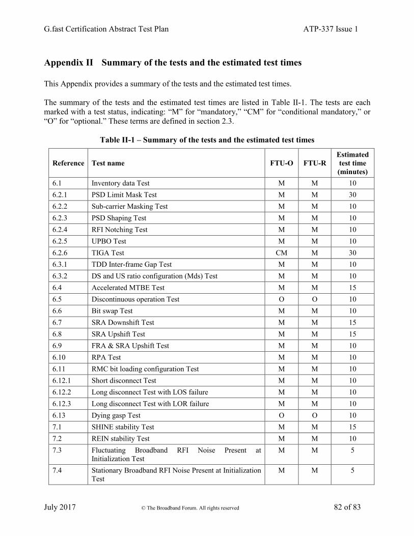
G.fast Certification Abstract Test Plan ATP-337 Issue 1
July 2017 © The Broadband Forum. All rights reserved 82 of 83
Appendix II Summary of the tests and the estimated test times
This Appendix provides a summary of the tests and the estimated test times.
The summary of the tests and the estimated test times are listed in Table II-1. The tests are each
marked with a test status, indicating: “M” for “mandatory,” “CM” for “conditional mandatory,” or
“O” for “optional.” These terms are defined in section 2.3.
Table II-1 – Summary of the tests and the estimated test times
Reference Test name FTU-O FTU-R
Estimated
test time
(minutes)
6.1 Inventory data Test M M 10
6.2.1 PSD Limit Mask Test M M 30
6.2.2 Sub-carrier Masking Test M M 10
6.2.3 PSD Shaping Test M M 10
6.2.4 RFI Notching Test M M 10
6.2.5 UPBO Test M M 10
6.2.6 TIGA Test CM M 30
6.3.1 TDD Inter-frame Gap Test M M 10
6.3.2 DS and US ratio configuration (Mds) Test M M 10
6.4 Accelerated MTBE Test M M 15
6.5 Discontinuous operation Test O O 10
6.6 Bit swap Test M M 10
6.7 SRA Downshift Test M M 15
6.8 SRA Upshift Test M M 15
6.9 FRA & SRA Upshift Test M M 10
6.10 RPA Test M M 10
6.11 RMC bit loading configuration Test M M 10
6.12.1 Short disconnect Test M M 10
6.12.2 Long disconnect Test with LOS failure M M 10
6.12.3 Long disconnect Test with LOR failure M M 10
6.13 Dying gasp Test O O 10
7.1 SHINE stability Test M M 15
7.2 REIN stability Test M M 10
7.3 Fluctuating Broadband RFI Noise Present at
Initialization Test
M M 5
7.4 Stationary Broadband RFI Noise Present at Initialization
Test
M M 5

G.fast Certification Abstract Test Plan ATP-337 Issue 1
July 2017 © The Broadband Forum. All rights reserved 83 of 83
7.5 Fluctuating Broadband RFI Noise Present at Showtime
Test
M M 5
7.6 Stationary Broadband RFI Noise Present at Showtime
Test
M M 5
8.1.1 Single-line Basic Throughput Test M M 45
8.2.1 Multi-line Basic Throughput Test CM M 60
8.2.2 Multi-line Disorderly Shutdown Test CM M 5
Estimated total test time for ATP-337 420
End of Broadband Forum Abstract Test Plan ATP-337