+GF+ SIGNET 9010 Intelek-Pro Flow Controller - KTH Sales · The +GF+ SIGNET 9010 Intelek-Pro Flow...
36
+ GF + SIGNET 9010 Intelek-Pro Flow Controller Instruction Manual GEORGE FISCHER + GF + FLOW CONTROLLER + GF + SIGNET
Transcript of +GF+ SIGNET 9010 Intelek-Pro Flow Controller - KTH Sales · The +GF+ SIGNET 9010 Intelek-Pro Flow...

+GF+ SIGNET 9010 Intelek-Pro
Flow Controller
Instruction Manual
GEORGE FISCHER +GF+
FLOW CONTROLLER
+GF+ SIGNET

Danger: Avoid electric shock. Do not connectpower when the instrument cover is partially orcompletely removed.
Important safety information

Table ofContents
Chapter Page
1 Introduction 11.1 Introduction 11.2 Front Panel Description 21.3 Rear Panel Description 3
2 Installation and Operation 42.1 Mounting Instructions 42.2 Power Connections 52.3 Input Connections 62.4 Standard Output Connections 72.5 Relay Output Connections 82.6 Verifying Analog Outputs 92.7 Analog Output Connections 10
3 System Configuration 103.1 Introduction 103.2 Calibration Menu, Frequency Inputs 123.3 Calibration Menu, Analog Inputs 123.4 2-Relay Operations 153.5 Calibration Menu, 2-Relay 163.6 Calibration Menu, Analog Outputs 173.7 View-Only Menus 18
4 Technical Support 194.1 Accessing Internal Options 194.2 AC Power Configurations 194.3 Installing Input/Output Options 204.4 Option Cards and Accessories 214.5 Input Card Configuration 224.6 Output Card Configuration 234.7 Troubleshooting 23
Specifications 24Warranty Information 26
Unpacking and Inspection
Your flow controller package includes thefollowing items:
• +GF+ SIGNET 9010 Intelek-Pro FlowController
• Two stainless steel mounting brackets• Mounting Instructions w/self-adhesive
template• Panel gasket• Instruction manual w/assorted engineering
labels
Warranty RecordFor your protection, record your unit's purchaseinformation for future reference. The serialnumber decal is located on the instrument's rearpanel.
Model: +GF+ SIGNET 9010 Intelek-Pro FlowController
Purchase Date: ________________________
Serial Number: _________________________
Purchased From: ________________________
Purchase Order Number: ________________

Chapter 1
Introduction
1.1 IntroductionYour new +GF+ SIGNET 9010 Intelek-Pro FlowController has been specifically designed for liquidflow rate measurement in process pipes. Thecontroller's compact 1/4 DIN enclosure (front) isNEMA 4X/IP65 rated and ideal for installing intoinstrumentation panels with limited space.
Modular "plug-in" input/output option cards allowyou to customize your flow controller to your flowsystem's requirements. The controller's unique"slide-out" chassis design makes option installationfast and simple. Smart self-configuringmicroprocessor based circuitry automaticallyinventories installed options during power-up,allowing you to upgrade your system in secondswithout the need for additional equipment.
The unit's front panel features a highly visible4.5- digit (seven segment) and 8-digit (alpha-numeric) liquid crystal display with adjustablecontrast. Active flow rate, accumulation, andalarm relay information is quickly accessed at aglance. During calibration the user is promptedwith clear step-by-step instructions on the unit's frontpanel display.
The +GF+ SIGNET 9010 Intelek-Pro FlowController is fully compatible with all +GF+ Signetflow sensor products, yet also accepts otheranalog inputs, such as 4 to 20 mA or0 to 5 VDC etc.
The technical data given inthis publication is for generalinformation purposes only. Itimplies no warranty ofwhatever kind.
1

5.
Item FunctionIndicate activation status of optional output "alarm" relays 1 & 2
8.
Most engineering units and blanks available for custom applications (included).User selected and installed for specific applications.
1. Relay An-nunciators:
2. LCDDisplay:
Shows flow, calibration, accumulation, and relay activation status information
3. A) Accesses one of three calibration menus: CAL, RELAY, OUT B) Enables acalibration parameter for modification C) Restores a calibration parameter toit's original value during calibration
A) Stores a calibration value into memory after modification B) Used to displayavailable input/output options during normal operation.
4.
6. A) Accesses the RELAY "view-only" menu B) Used in conjunction with MOD keyto access the RELAY calibration menu
A) Accesses the OUTPUT "view-only" menu B) Used in conjunction with MODkey to access the OUTPUT calibration menu
7.
Decreases the value of a selected calibration digit
Increases the value of a selected calibration digit9.
10. A) Returns the unit to normal operation mode B) Selects a digit for modificationduring calibration
11. Unit Tags
A) Accesses the CAL "view-only" menu B) Used in conjunction with MOD keyto access the main CAL menu
MOD
CAL
ENTER
RELAY
OUTPUT
FLOW
FLOW CONTROLLER
ENTER MODFLOW
CAL RELAY OUTPUT
RLY 1RLY 2
GPM
2
3
4
5
6
1
7
8
9
10
11
+GF+ SIGNET
Item 11:Remove front bezelto change unit tagsunder clear overlaywindow. The unittags are attachedto the rear coverof the manual.
2
1.2 Front Panel Description
Item
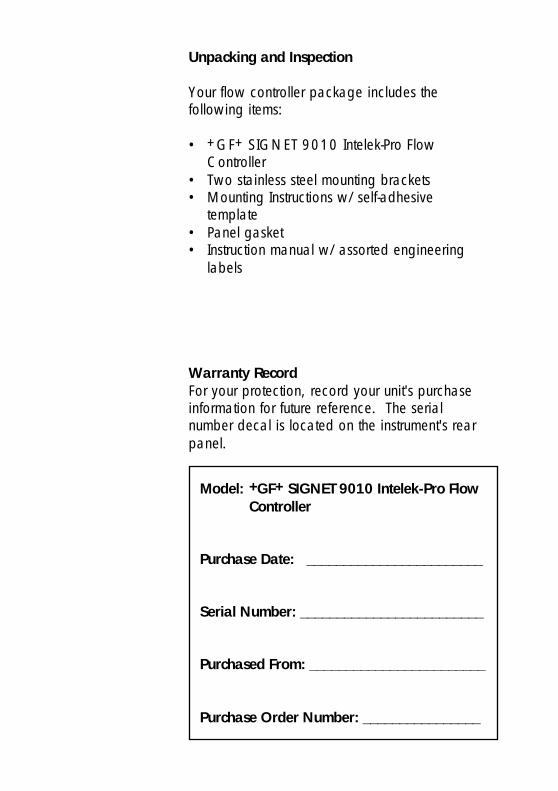
17 to 30 VDC system power connection 2. DC IN
1. AC IN
Alarm relay #1 (COM, NO, NC) contact set for externaldevice control (optional)
3. RLY 1
4. RLY 2Alarm relay #2 (COM, NO, NC) contact set for externaldevice control (optional)
6. Sensor
Analog output #1 from option socket #1 (optional) 5. ANL1
Analog signal input connection (optional)
Serial outputs (future availability)
Analog output #2 from option socket #2 (optional) 9. ANL2
8. Serial
7. A in
CNT emits an open collector pulse output for each incrementof totalizer. PLS emits a TTL frequency output in phase with thesensor input
10. Output
11. SSUnused Terminal
Note: Rear terminalsaccept 18 to 22 AWGwire
1 2 3 4 5 6 7 8 9 10 11 12 13 14
15 16 17 18 19 20 21 22 23 24 25 26 27 28
SS CNT GND PLS
OUTPUT ANL2
R+ R-
SERIAL
Tx GND Rx
A in
A+ A- BLK RED SHLD
SENSOR
L1 N
AC IN
+ GND NO C NC
RLY1DC INNO C NC
RLY2
R+ R-ANL1
10 9 8 7 6
1 2 3 4 5
11
Flow sensor input connection (frequency)
90 to 132 VAC or 180 to 264 VAC system powerconnection
Function
3
1.3 Rear Panel Description
2.1 Mounting InstructionsThe +GF+ SIGNET Intelek-Pro Flow Controller's1/4 DIN enclosure is specifically designed forpanel mounting. Adjustable mounting bracketsallow mounting in panels up to 1 in./25 mm thick.An adhesive template and instructions are includedto insure proper installation.
For outdoor and/or stand alone installations thesplash-proof NEMA 4X/IP65 back cover kit isrecommended (ordered separately).
Figure 1External dimensions
5.7 in./145 mm6 in./152 mm
7.2 in./183 mm
Mounting Clamp (included, 2 ea.)
*Optional NEMA 4X/IP65 Rear Cover
3.8 in. sq.96 mm
3.5 in.88 mm
Mounting PanelMax. panel thickness = 1 in./25 mm
PanelGasket
SIDE VIEW
6.5 in./165 mm
Panel Cutout InstructionsRecommended panel cutout 3.54 in./90 mm square. Maximum panel cutout 3.62 in./92 mm square, DO NOT exceed. Use adhesive backed template (included)
4
Chapter 2
InstallationandOperation

2.2 Power Connections
AC Power Connections
Instructions1. Jumper selectable for 90 to 132 OR 180 to264 VAC operation. Confirm AC power configurationbefore applying power. See section 4.2 pg# 19
2. *A direct or low impedance AC ground (earthground) MUST be used for proper operation.
3. To reduce the possibility of noise interference, ACpower lines must be isolated from signal lines.
DC Power Connections
Note: AC/DC power can be connected simultaneously,using DC power as an uninterrupted power source.
*A direct or low impedance earth ground MUST be usedfor optimum performance.
15 16 17 18 19 20 21 22 23 24 25 26 27 28
L1 N
AC IN
+ GND NO C NC
RLY1DC IN
NO C NC
RLY2
R+ R-
ANL1
90 to 132 VACOR180 to 264 VAC
AC HotAC Ground*AC Neutral
5
Figure 2AC power wiring
Figure 3DC power wiring
Danger: Avoid electricshock. Do not connect powerwhen the instrument cover ispartially or completelyremoved.
DC power is recommendedwhen ground fault interruptdevices (GFI's) are used.
L1 N
AC IN
+ GND NO C NC
RLY1DC IN
NO C NC
RLY2
R+ R-
ANL1
17 to 30 VDC @ 0.5 A GND
15 16 17 18 19 20 21 22 23 24 25 26 27 28
*
SS CNT GND PLS
OUTPUT ANL2
R+ R-
SERIAL
Tx GND Rx
A in
A+ A- BLK RED SHLD
SENSOR
1 2 3 4 5 6 7 8 9 10 11 12 13 14
Analog Input:Current or Voltage
R+
R-
C
SHIELD
RED
BLACKA&B
External DCPower Supply
-
+
ORFrequency Input:
for Signet sensors and others
+GF+ SIGNET8512
+ -
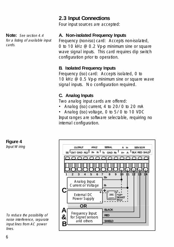
2.3 Input ConnectionsFour input sources are accepted:
A. Non-isolated Frequency InputsFrequency (non-iso) card: Accepts non-isolated,0 to 10 kHz @ 0.2 Vp-p minimum sine or squarewave signal inputs. This card requires dip switchconfiguration prior to operation.
B. Isolated Frequency InputsFrequency (iso) card: Accepts isolated, 0 to10 kHz @ 0.5 Vp-p minimum sine or square wavesignal inputs. No configuration required.
C. Analog InputsTwo analog input cards are offered:• Analog (iso) current, 4 to 20/0 to 20 mA• Analog (iso) voltage, 0 to 5/0 to 10 VDCInput ranges are software selectable, requiring nointernal configuration.
Note: See section 4.4for a listing of available inputcards.
Figure 4Input Wiring
6
To reduce the possibility ofnoise interference, separateinput lines from AC powerlines.

1 2 3 4 5 6 7 8 9 10 11 12 13 14
SS CNT GND PLS
OUTPUT ANL2
R+ R-
SERIAL
Tx GND Rx
A in
A+ A- BLK RED SHLD
SENSOR
Red (2)
Shld (3)
+GF+ SIGNETIndicator or ControllerORTTL Compatible Device
Input
Gnd
Gnd 5 to 30 VDCPower Supply+
External counteror accumulator
IN
Gnd
600Ω @ >1.5 W
To reduce the possibility ofnoise interference, separateoutput lines from AC powerlines.
Figure 5Sensor pulse output (PLS)/counter output (CNT)wiring
7
2.4 Standard Output Connections
Standard OutputsAn open collector counter pulse output (CNT) anda sensor pulse output (PLS) are included with yourunit.
The counter pulse output (synchronous w/totalizer)emits an open collector 150 ms pulse with amaximum current sinking capacity of 50 mA @30 VDC, and is ideal for driving an externalcounter or accumulator. An external DC powersupply and current limiting resistor are requiredfor operation.
The sensor pulse output (PLS) emits a standard TTLfrequency output in phase with the sensor inputand can be used to drive +GF+ SIGNETinstruments (except +GF+ SIGNET 5090 and5091) and other TTL compatible devices.
8
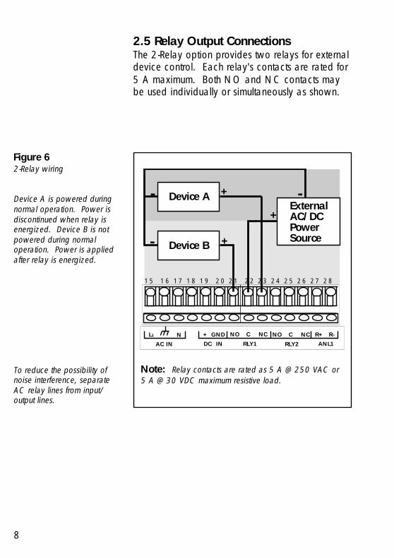
2.5 Relay Output ConnectionsThe 2-Relay option provides two relays for externaldevice control. Each relay's contacts are rated for5 A maximum. Both NO and NC contacts maybe used individually or simultaneously as shown.
Note: Relay contacts are rated as 5 A @ 250 VAC or5 A @ 30 VDC maximum resistive load.
To reduce the possibility ofnoise interference, separateAC relay lines from input/output lines.
15 16 17 18 19 20 21 22 23 24 25 26 27 28
L1
AC IN
+ GND NO C NC
RLY1DC IN
NO C NC
RLY2
R+ R-
ANL1
Device A
Device B
ExternalAC/DCPowerSource
+
-
+
+-
-
N
Figure 62-Relay wiring
Device A is powered duringnormal operation. Power isdiscontinued when relay isenergized. Device B is notpowered during normaloperation. Power is appliedafter relay is energized.
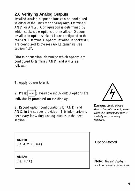
ANL1=(i.e. 4 to 20 mA)
ANL2=(i.e. N/A)
2.6 Verifying Analog OutputsInstalled analog output options can be configuredto either of the unit's rear analog output terminals:ANL1 or ANL2. Configuration is determined bywhich sockets the options are installed. Optionsinstalled in option socket #1 are configured to therear ANL1 terminals, options installed in socket #2are configured to the rear ANL2 terminals (seesection 4.3).
Prior to connection, determine which options areconfigured to terminals ANL1 and ANL2 asfollows:
1. Apply power to unit.
2. Press: ENTER ; available input/output options areindividually prompted on the display.
3. Record option configurations for ANL1 andANL2 in the spaces provided. This information isnecessary for wiring analog outputs in the nextsection.
9
Option Record
Danger: Avoid electricshock. Do not connect powerwhen the instrument cover ispartially or completelyremoved.
Note: The unit displaysN/A for unavailable options.
10
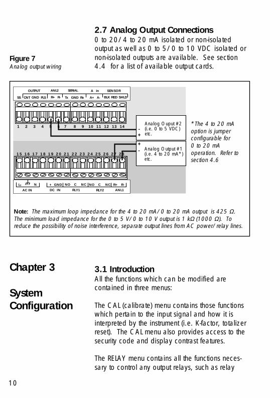
2.7 Analog Output Connections0 to 20/4 to 20 mA isolated or non-isolatedoutput as well as 0 to 5/0 to 10 VDC isolated ornon-isolated outputs are available. See section4.4 for a list of available output cards.
Chapter 3
SystemConfiguration
3.1 IntroductionAll the functions which can be modified arecontained in three menus:
The CAL (calibrate) menu contains those functionswhich pertain to the input signal and how it isinterpreted by the instrument (i.e. K-factor, totalizerreset). The CAL menu also provides access to thesecurity code and display contrast features.
The RELAY menu contains all the functions neces-sary to control any output relays, such as relay
Note: The maximum loop impedance for the 4 to 20 mA/0 to 20 mA output is 425 Ω.The minimum load impedance for the 0 to 5 V/0 to 10 V output is 1 kΩ (1000 Ω). Toreduce the possibility of noise interference, separate output lines from AC power/relay lines.
Figure 7Analog output wiring
*The 4 to 20 mAoption is jumperconfigurable for0 to 20 mAoperation. Refer tosection 4.6
SS CNT GND PLS R+ R- Tx GND Rx A+ A- BLK RED SHLD
OUTPUT ANL2 SERIAL A in SENSOR
Analog Ouput #2(i.e. 0 to 5 VDC)etc.
-+
L1
AC IN
+ GND NO C NC
RLY1DC IN
NO C NC
RLY2 ANL1
- Analog Output #1(i.e. 4 to 20 mA*)etc.
+
1 2 3 4 5 6 7 8 9 10 11 12 13 14
1 5 1 6 1 7 1 8 1 9 2 0 2 1 2 2 2 3 2 4 2 5 2 6 2 7 2 8
R+ R-N
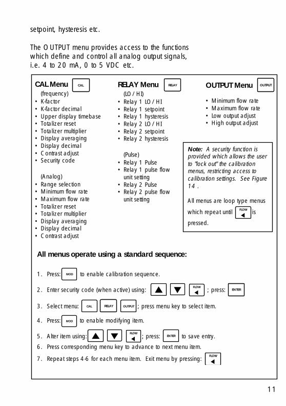
CAL Menu(frequency)
• K-factor• K-factor decimal• Upper display timebase• Totalizer reset• Totalizer multiplier• Display averaging• Display decimal• Contrast adjust• Security code
(Analog)• Range selection• Minimum flow rate• Maximum flow rate• Totalizer reset• Totalizer multiplier• Display averaging• Display decimal• Contrast adjust
setpoint, hysteresis etc.
The OUTPUT menu provides access to the functionswhich define and control all analog output signals,i.e. 4 to 20 mA, 0 to 5 VDC etc.
CAL OUTPUT Menu
• Minimum flow rate• Maximum flow rate• Low output adjust• High output adjust
OUTPUTRELAY Menu(LO/HI)
• Relay 1 LO/HI• Relay 1 setpoint• Relay 1 hysteresis• Relay 2 LO/HI• Relay 2 setpoint• Relay 2 hysteresis
(Pulse)• Relay 1 Pulse• Relay 1 pulse flow
unit setting• Relay 2 Pulse• Relay 2 pulse flow
unit setting
RELAY
Note: A security function isprovided which allows the userto "lock out" the calibrationmenus, restricting access tocalibration settings. See Figure14 .
All menus are loop type menus
which repeat until FLOW is
pressed.
All menus operate using a standard sequence:
1. Press: MOD to enable calibration sequence.
2. Enter security code (when active) using: FLOW ; press: ENTER
3. Select menu: CAL RELAY OUTPUT ; press menu key to select item.
4. Press: MOD to enable modifying item.
5. Alter item using: FLOW
; press: ENTER to save entry.
6. Press corresponding menu key to advance to next menu item.
7. Repeat steps 4-6 for each menu item. Exit menu by pressing: FLOW
11
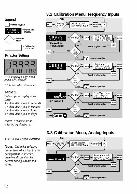
3.2 Calibration Menu, Frequency InputsLegend
= Press Keypad
= Intelek-Pro Display
= Decision Block
= Calibration procedure
1 8 8 8 8 X X X X X X X X
Table 1Select upper display time-base:1= flow displayed in seconds2= flow displayed in minutes3= flow displayed in hours4= flow displayed in days
Note: Accumulator notaffected by timebase.
"1" is displayed only whenpreviously selected.
"1" flashes when deselected.
K-factor Setting
MOD SecurityCode?
Yes Unlock security code using:
ENTERModify?
No
Yes
Selectnext item?
Yes
FLOW
Press toset K-factor from.0001 to 19999.
1 9 9 9 9K - F A C T O R
MOD
Normal operation
ENTER
Recall original valueMOD
No
CAL
No
CAL
Decimal setin next step
ENTERModify?
No
Yes
Selectnext item?
YesCAL
FLOW
Press to select decimal location, 0-4 plcs.
1 8 8 8 8K - f D P = 0
MOD
Normal operation
Recall original valueMOD
No
ENTERModify?
No
Yes
Selectnext item?
YesCAL
FLOW
Press to select upper display timebase (1-4)
2 T I M E B A S E
MOD
Normal operation
Recall original valueMOD
NoGo to A
See Table 1
3.3 Calibration Menu, Analog Inputs4 to 20 mA option illustrated
Note: The unit's softwarerecognizes which input card/configuration is inserted,therefore displaying thecorresponding calibrationvalue.
MOD SecurityCode?
Yes Unlock security code using: ENTER
No
CAL
ENTERModify?
No
Yes
Selectnext item?
YesCAL
FLOW
Press to selectoperation range,(4-20 or 0-20 mA)
MOD
Normal operation
4m A = 0 o r 4
Recall original valueMOD
No
12

Exiting Menu
Menu will repeat until FLOW
is pressed.
Go to A
ENTERModify?
No
Yes
Selectnext item?
YesCAL
FLOW
Press toenter maximumflow rate
MOD
Normal operation
1 8 8 8 82 0 m A I S
Recall original valueMOD
No
ENTERModify?
No
Yes
Selectnext item?
YesCAL
FLOW
Press toenter minimum flow rate
MOD
Normal operation
1 8 8 8 8 4 m A I S
Recall original valueMOD
No
Continued
ENTERModify?
No
Yes
Selectnext item?
YesCAL
FLOW
Press to reset totalizer to zeroT O T L
X X X X X X X XMOD
Normal operation
ENTERModify?
No
Yes
Selectnext item?
YesCAL
FLOW
Press to select multiplier; X0.1,X1,X10,X100,X1000
1T O T L X
MOD
Normal operation
Recall original valueMOD
Recall original valueMOD
No
No
A
ENTERModify?
No
Yes
Selectnext item?
YesCAL
FLOW
Press to selectaveraging time, 2-10 seconds
0 2F L O A V R G
MOD
Normal operation
Recall original valueMOD
No
13

ENTERModify?
No
Yes
Selectnext item?
YesCAL
FLOW
Press to select best contrast
1 8 8 8 8C O N T R A S T
MOD
Normal operation
ENTERModify?
No
Yes
Repeatmenu?
YesCAL
FLOW
Press to select personalsecurity code
0 0 0 0S E C C O D E
MOD
Normal operationNo
Recall original valueMOD
Recall original valueMOD
No
ENTERModify?
No
Yes
Selectnext item?
YesCAL
FLOW
Press to select display decimal,0-4 places
- - - . - -F L O D P = 2
MOD
Normal operation
Recall original valueMOD
No
14

3.4 2-Relay OperationsThe 2-Relay option allows you to configureindividual setpoints, LO or HI operation, andhysteresis values for two independent on/offrelays.
• Relay Setpoints: Setpoints represent the flowrate at which each relay is energized.
• Relay Hysteresis: Hysteresis values directlyeffect the LO and HI relay modes, specifying howfar the flow will rise above (LO Relay Mode) or fallbelow (HI Relay Mode) each relay's setpoint priorto de-energizing the relay. The main purpose forhysteresis is to eliminate relay "chatter", caused bya flow hovering around a relay's setpoint.Hys-teresis values are programmed in direct flowunits and must be less than the corresponding relaysetpoint. Hysteresis only applies when exiting analarm condition.
• LO Relay Operation: In LO operation, the relayis energized when the flow drops below theset-point, and is de-energized when the flow risesabove the setpoint plus hysteresis. See Figure 8.
• HI Relay Operation: In HI operation, the relayis energized when the flow rises above thesetpoint and is de-energized when the flow fallsbe-low the setpoint plus hysteresis. See Figure 9.
• Pulse Relay Setting: Setting relay 1 or 2 to thePulse operation mode means the relay will becycled (energized) for a 150 ms period each timea user specified quantity is measured.
Figure 9HI relay operation mode
= HI setpoint
= Hysteresis
= Relay energized
= Relay de-energized
Flow
Figure 8LO relay operation mode
= LO setpoint
= Hysteresis
= Relay energized
= Relay de-energized
Flow
15

Note: Displayed decimalposition set by CAL menuK-factor
Note: Relay cannot exceed4 pulses per second.
Exiting MenuMenu will repeat until FLOW
is pressed.
Relay 2 LO, HIGH, or PULSE, go to: A
MOD SecurityCode?
Yes Unlock security code using:
Selectnext item?
YesRELAY
FLOW Normal operation
ENTER
Recall original value
Modify?
No
Yes Press to select relay operation modeLO, HIGH, or PULSE
L O R L Y 1 I S
MOD
MOD
No
Modify?
No
Yes
Selectnext item?
YesRELAY
FLOW
Press to set relay setpoint 0 1 0 0
S E T R L Y 1 MOD
Normal operation
Recall original valueMOD
Modify?
No
Yes
Selectnext item?
Yes
FLOW
Press to select relay hysteresis
0 0 2 0 S E T H Y S 1
MOD
Normal operation
Recall original valueMOD
No PULSEMode
?Yes
Go to
ENTERModify?
No
Yes Press to set pulse units (0.1 to 9999999.9)
r L Y 1 X X X X X X X . X
MOD
MODRecall original value
RELAY
No
No
No
A
RELAY
B
Relay 2 LO, HIGH, or PULSE, go to: A
B
ENTER
ENTER
ENTER
3.5 Calibration Menu, 2-Relay
16

Exiting MenuMenu will repeat until FLOW is pressed.
4 to 20/0 to 20 mA (iso/non-iso) options illustratedMOD Security
Code?Yes Unlock security
code using:
Selectnext item?
Yes
FLOW Normal operation
ENTER
Recall original value
ENTERModify?
No
Yes 9 9 9 9 A N L 1 4 m
MOD
MOD
No
ENTERModify?
No
Yes
Selectnext item?
Yes
FLOW
9 9 9 9 A N L 1 2 0 m
MOD
Normal operation
Recall original valueMOD
ENTERModify?
No
Yes
Selectnext item?
Yes
Press to fine tune4 mA output signal.See note*
4A D J U S T
MOD
FLOW Normal operation
Recall original valueMOD
ENTERModify?
No
Yes 2 0 A D J U S T
MOD
MODRecall original value
OUTPUT
Press to selectflow rate at 20 mA output signal
Press to selectflow rate at 4 mA output signal
OUTPUT
OUTPUT
OUTPUT
Ammeter required, see Figure 10
Press to fine tune 20 mA output signal.See note*
RepeatMenu?
Yes
FLOW Normal operation
OUTPUT
Ammeter required, see Figure 10
No
No
No
No
*Note: Press: FLOW to
quickly access the minimum ormaximum current output signal
Press: to finetune the current output signal
1 2 3 4 5 6 7 8 9 10 11 12 13 14
15 16 17 18 19 20 21 22 23 24 25 26 27 28
SS CNT GND PLS
OUTPUT ANL2
R+ R-
SERIAL
Tx GND Rx
A in
A+ A- BLK RED SHLD
SENSOR
L1 NAC IN
+ GND NO C NC
RLY1DC INNO C NC
RLY2
R+ R-ANL1
R+R-
R+R-
AMMETER
Figure 10The min. and max. currentadjustment steps require anexternal ammeter for monitor-ing the current output.
3.6 Calibration Menu, Analog Outputs
17

Flow rate settingfor 4 mA outputOUTPUT
Flow rate settingfor 20 mA output
CAL K-factor TotalizerResolution
Flow displayaveraging
Flow displaydecimal pt.
Relay 1 LO, HI,or Pulse
Relay 1setpoint
Relay 1 hysteresisRELAY
Relay 2 LO, HI,or Pulse
Relay 2setpoint
Relay 2 hysteresis
Output view-only menu: 4 to 20 mA (iso/non-iso) output option illustrated
Relay view-only menu: 2-Relay LO/HI output option illustrated
Main (CAL) view-only menu: Frequency (iso/non-iso) input option illustrated
3.7 View-Only MenusThree "view-only" menus (CAL, RELAY, andOUTPUT) are available during normal operation.Each view only menu provides the operator ameans of browsing through calibration settingswithout disturbing system calibration and/or theflow process. When used in conjunction with thesecurity feature, the view only menus allow anoperator access to limited calibration informationon the front display, excluding the ability tochange system parameters without the supervisorsapproval and personal security code.
Access each of the three view only menus bypressing the corresponding menu key. Afterentering each of the three view only menus, eachcalibration parameter is sequentially displayed onthe main and lower displays by successivelypressing it's corresponding menu key as follows:
Exiting Menus: Exit viewonly menus at any time by
pressing: FLOW
Note: The view-only menusare designed for viewing onlyand DO NOT permit accessfor calibration of any kind.Menus will vary dependingupon installed options.
18
19
4.2 AC Power ConfigurationsTwo AC power options are possible; 90 to 132VAC, or 180 to 264 VAC. Each power option isselectable via internal jumpers on the main pcboard. See Figure 14
Warning: Check ACconfiguration before applyingpower to unit.
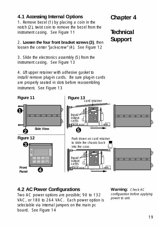
4.1 Accessing Internal Options1. Remove bezel (1) by placing a coin in thenotch (2), twist coin to remove the bezel from theinstrument casing. See Figure 11
2. Loosen the four front bracket screws (3), thenloosen the center "jack-screw" (4). See Figure 12
3. Slide the electronics assembly (5) from theinstrument casing. See Figure 13
4. Lift upper retainer with adhesive gasket toinstall/remove plug-in cards. Be sure plug-in cardsare properly seated in slots before reassemblinginstrument. See Figure 13
Figure 13
Figure 12
Figure 11
Chapter 4
TechnicalSupport
Push down on card retainer to slide the chassis backinto the case.
Input/output cards
card retainer
5Side View
1
2
Front Panel
RLY 1RLY 2RLY 3RLY 4
3
4
Input/output cards

Input Card Dedicated for input cards
Output Card #1 Accepts all analog output cards
Output Card #2 Accepts all analog output cards
Output Card #3 Dedicated for the 2-Relay output card.
Socket Labeled Compatible Options
Figure 14Main PC Board
4.3 Installing Input/Output OptionsInput/output option cards are "keyed" for properinsertion into four sockets. Sockets are located onthe unit's main pc board and are clearly marked.See Figure 14 and table below:
INPU
T C
ARD
OUTPUT CARD #1
OUTPUT CARD #2
OU
TPU
T C
ARD
#3
Option SocketsSecurity Feature
1 2 3 4
OPEN
12
34
OPEN
OR180 to 264 VAC
operation 90 to 132 VAC
operation
BlueJumpers
Enable the security feature by setting positon #1 "closed"
OPEN
Disable the security feature by setting positon #1 "open"
Fuse, 1/4 A @ 250 VAC (fast blow)
1 2 3 4
20

3-9010.400-1 (requires configuration) Frequency Input (non-isolated) 198 840 621See section 4.5
Part Number Input Cards Code
Part Number Accessories Code
Part Number Output Cards Code
3-9010.650 Assorted engineering labels 198 840 205
3-9000.440-1 2-Relay card 198 849 641
4.4 Option Cards and Accessories
3-9010.400-3 4 to 20/0 to 20 mA input 198 840 623 (isolated)
3-9010.400-2 (configuration not Frequency Input (isolated) 198 840 622required)
3-9000.450-1 (requires configuration) 4 to 20/0 to 20 mA 198 840 631See section 4.6 (non-isolated)
3-9010.400-4 0 to 5/0 to 10 VDC input 198 840 624 (isolated)
3-9000.450-3 0 to 10 VDC (non-isolated) 198 840 633
3-9000.450-2 0 to 5 VDC (non-isolated) 198 840 632
3-9000.460-1 (requires configuration) 4 to 20/0 to 20 mA (isolated) 198 840 634See section 4.6
3-9000.460-2 0 to 5 VDC (isolated) 198 840 635
3-9000.460-3 0 to 10 VDC (isolated) 198 840 636
3-5000.395 NEMA 4X/IP65 back cover 198 840 227
3-5000.399 +GF+ SIGNET mounting 198 840 224adapter plate
21
3-9000.392 Conduit connector kit for 198 840 217 NEMA 4X back cover (includes 3 connectors)

3-9000.525-1 Front bezel 198 840 206
3-9000.575 Panel mounting gasket 198 840 207
Part Number Spare Parts Code
6400-0019 Fuse, 1/4 A @ 250 VAC (fast blow) 198 840 208
2400-0404 Front cover screws (4 each) 198 840 209
3-9000.570 Front cover gasket 198 840 210
3-9000.560 Mounting Clamp 198 840 216
*Dip switch factory configured for the +GF+ SIGNET 515 Rotor-X Paddlewheel Flow Sensor.
22
+GF+Signet Dip switch settingsSensor 1234 Function508 1011 5 VDC power to sensor2502 with pull down resistor
515 1111* No power to sensor withTTL inputs pulldown resistor
525 1110 No power to sensor with no2515 pulldown resistor2717
2000 1001 5 VDC power to sensor2507 with pull up resistor253625402550
4.5 Input Card ConfigurationThe non-isolated Frequency Input Card (Partnumber 3-9010.400-1) requires dip switchconfiguration prior to operation. See Figure 15
Figure 15Frequency (non-iso) input carddip switch settings
12
34
Frequency Input Card Dip Switch
0 1

Front Display
CAL Menu Error Codes
01: Reset K-factor/low setpoint02: Reset K-factor/high setpoint03: Reset Totalizer 04: Reset totalizer multiplier05: Reset flow averaging06: Reset flow decimal 07: Reset contrast08: Reset security code
OUTPUT Menu Error Codes
01: Recalibrate ANL 1 settings02: Recalibrate ANL 2 settings
RELAY Menu Error Codes
01: Reset relay 1 LO, HI or Pulse 02: Reset relay 1 flow/pulse setpoint 03: Reset reley 1 hysteresis 04: Reset relay 2 LO, HI or Pulse 05: Reset relay 2 flow/pulse setpoint 06: Reset relay 2 hysteresis
4.6 Output Card ConfigurationEach 4 to 20/0 to 20 mA (iso or non-iso) outputcard contains jumper selections for it's operationrange.
• Placing the blue jumper in the "A" positionconfigures the card for 4 to 20 mA operation.
• Placing the blue jumper in the "B" positionconfigures the card for 0 to 20 mA operation.
4.7 TroubleshootingError codes will be shown on the display after anabnormal occurrence, such as large amounts ofelectromagnetic interference or a large voltagetransient on the AC power line occur.
Displayed error codes represent corrupted setupdata in the internal memory which must be re-entered by the operator. See Figure 17
Figure 17Displayed error codes
Figure 164 to 20/0 to 20 mA outputcards
Isolated version
A
B
Blue Jumper
Non-isolated version
A B
Blue Jumper
23

Power Requirements17 to 30 VDC @ 0.5 A max. and/or90 to 132 VAC @ 50 to 60 Hz or180 to 264 VAC @ 50 to 60 Hz
Operating Temperature32 to 130 °F/0 to 55 °C
Relative Humidity95% R.H. max., non-condensing
EnclosureMaterials: ABS plasticRating: NEMA 4X/IP65 frontNEMA 4X/IP65 rear cover (optional)Dimensions: 3.5 X 3.5 X 6.0 in./88 X 88 X 165 mm
Memory BackupNon-volatile RAM
Liquid Crystal Display4.5 digits, 0.5 in./12.7 mm height (upper)8 digits, 0.3 in./7.6 mm height (lower)2 alarm annunciatorsAccuracy: 0-5 kHz input, 0.05% of reading
Display AveragingProgrammable from 2 to 10 seconds
Noise ImmunityExceeds IEC 801-2, level 3, IEC 801-3, level 2
Input SignalFrequency (iso or non-iso):Frequency range: 0 to 10 kHzK-factor range: .0001 to 19999.Minimum signal amplitude:Non-iso freq input: 0.2 Vp-p (continued)
Specifications
24

25
Isolated freq input: 0.5 Vp-pIsolation: 500 VDC to earth ground
Flow Current and Voltage (iso):Input range: 4 to 20 mA or 0 to 20 mA
0 to 5 VDC or 0 to 10 VDCIsolation: 500 VDC isolation to earth ground
Output SignalsSensor Pulse OutputTTL compatible synchronous with sensor inputMax. current sink: 20 mAMax. current source: 10 mA
Counter Pulse OutputOpen collector transistor synchronous with totalizerMax. current sink: 50 mA @ 30 VDC max.
2-RelayOutputs: Two SPDT contact outputs: 5 A @ 250VAC or 30 VDC resistive load max. current
Analog 4 to 20 or 0 to 20 mAResponse time: 2.5 s max. for 100% changeMaximum loop resistance: 425 ΩIsolation: 500 VDC to earth groundAccuracy: ±0.5% of full scale
Analog 0 to 5 or 0 to 10 VDCResponse time: 2.5 s max. for 100% changeMaximum loop resistance: 1 kΩ (1000 Ω)Isolation: 500 VDC to earth ground (optional)Accuracy: ±0.5% of full scale

U.S. WarrantyInformation
Limited Two-Year WarrantySignet Scientific Company warrants its instrumentsto be free from defects in material andworkmanship under normal use for a period of twoyears from the date of purchase by the initialowner, or three years from date of manufacture,whichever comes first, as described in thefollowing paragraphs.
This warranty does not cover defects caused byabuse or electrical damage. Signet ScientificCompany will not cover under warranty anyinstruments damaged during shipment to thefactory less case or if improperly packed. Repairattempts by anyone other than authorized servicepersonnel will void the warranty. Proof of date ofpurchase will be required before warranty repairscan begin. Transducers and cables will not becovered after installation.
Parts which prove to be defective in the first yearwill be repaired or replaced free of chargeincluding labor, shipped F.O.B. our factory or adesignated service center (addresses furnishedupon request).
Only non-moving parts, such as electricalcomponents, which prove defective during thesecond year are warranted. Meter movements willnot be covered. All units qualifying for warrantyservice after one year are subject to a servicecharge for replacement of non-moving parts.
Items returned for warranty repair must be shippedprepaid and insured. Warranty claims areprocessed on the condition that prompt notificationof a defect is given to Signet Scientific Companywithin the warranty period.
26

Signet Scientific Company shall have the sole rightto determine whether in fact a warranty situationexists.
Signet Scientific Company is continually makingdesign changes and improvements that adapt tothe original circuit configuration. These will beincorporated as required in older units on aminimal charge basis while under warranty.
Consequential DamagesSignet Scientific Company shall not be liable forspecial consequential damages of any nature withrespect to any merchandise or service sold,rendered or delivered.
This warranty gives you specific legal rights andyou may also have other rights which vary fromstate to state.
27

Notes:

Notes:

Notes:

+GF+ SIGNETSales Offices:USA George Fischer, Inc., 2882 Dow Avenue, Tustin, CA 92780/USA,
Tel. (714) 731-8800, Fax (714) 731-6201Switzerland Georg Fischer Rohrleitungssysteme AG, P.O. Box 671, CH-8201 Schaffhausen/Switzerland,
Tel. 052/631 1111, Fax 052/631 2830Singapore George Fischer Pte. Ltd., 15 Kaki Bukit Road 2, KB Warehouse Complex, Singapore 1441,
Tel. 65/747 0611, Fax 65/747 0577Japan Kubota George Fischer, 2-47 Shikitsuhigashi, 1-Chome, Naniwa-Ku, Osaka, 556-91 Japan,
Tel. 816/648 2545, Fax 816/648 2565China Georg Fischer Ltd., Rm 1503, Business Residence Bldg. of Asia Plaza, 2-3 Bldg. No. 5th
Qu Anzhenxili, Chaoyang Qu, Beijing 100029, P.R. China,Tel. 86/10 6443 0577, Fax 86/10 6443 0578
Australia George Fischer Pty. Ltd., Suite 3, 41 Stamford Road, Oakleigh, Victoria 3166, Australia,Tel. 61/3 9568 0966, Fax 61/3 9568 0988
Signet Scientific Company, 3401 Aerojet Avenue, El Monte, CA 91731-2882 U.S.A.,Tel. (626) 571-2770, Fax (626) 573-2057
GEORGE FISCHER +GF+ Piping Systems © Signet Scientific Company 1993 Printed in U.S.A.
PRINTED ON RECYCLED PAPER
3-9010.090 E-8/98