Getting Started with PSoC® 4 - San Jose State University Started with... · microcontroller unit...
19
www.cypress.com Document No. 001-79953 Rev. *I 1 AN79953 Getting Started with PSoC ® 4 Authors: Nidhin M S and Ronny Liu Associated Code Example: AN79953.zip Associated Part Family: All PSoC 4 parts Software Version: PSoC Creator™ 3.2 and higher To get the latest version of this application note or the associated code example, please visit http://www.cypress.com/go/AN79953 . AN79953 introduces you to PSoC ® 4, an ARM ® Cortex ® -M0 based programmable system-on-chip. It helps you explore the PSoC 4 architecture and development tools and shows you how to create your first project using PSoC Creator™, the development tool for PSoC 4. This application note also guides you to more resources to accelerate in-depth learning about PSoC 4. Contents Introduction .......................................................................1 PSoC Resources ...............................................................2 PSoC Creator ...............................................................2 Code Examples ............................................................3 PSoC Creator Help.......................................................4 Technical Support ........................................................4 PSoC 4 Feature Set ..........................................................5 PSoC is More Than an MCU .............................................7 My First PSoC 4 Design ....................................................8 About the Design ..........................................................8 Part 1: Create the Design .............................................8 Part 2: Program the Device ........................................ 16 Summary ......................................................................... 17 Worldwide Sales and Design Support ............................. 19 Introduction PSoC 4 is a true programmable embedded system-on- chip, integrating custom analog and digital peripheral functions, memory, and an ARM Cortex-M0 microcontroller on a single chip. This type of system is different from most mixed-signal embedded systems, which use a combination of a microcontroller unit (MCU) and external analog and digital peripherals. Such systems typically require many integrated circuits in addition to the MCU, such as opamps, ADCs, and application-specific integrated circuits (ASICs). PSoC 4 provides a low-cost – as low as US $0.29 in production volumes – alternative to the combination of MCU and external ICs. In addition to reducing overall system cost, the programmable analog and digital subsystems allow great flexibility, in-field tuning of the design, and speedy time to market. The capacitive touch-sensing feature in PSoC 4, known as CapSense ® , offers unprecedented signal-to-noise ratio; best-in-class waterproofing; and a wide variety of sensor types such as buttons, sliders, track pads, and proximity sensors. PSoC 4 offers a best-in-class current consumption of 150 nA while retaining SRAM, programmable logic, and the ability to wake up from an interrupt. PSoC 4 consumes only 20 nA while maintaining wakeup capability in its nonretention power mode. The PSoC 4 family of devices also contains PSoC 4 BLE, which integrates a Bluetooth Low Energy (BLE) radio system. For more details, see AN91267, Getting Started with PSoC 4 BLE.
Transcript of Getting Started with PSoC® 4 - San Jose State University Started with... · microcontroller unit...

www.cypress.com Document No. 001-79953 Rev. *I 1
AN79953
Getting Started with PSoC® 4
Authors: Nidhin M S and Ronny Liu
Associated Code Example: AN79953.zip
Associated Part Family: All PSoC 4 parts
Software Version: PSoC Creator™ 3.2 and higher
To get the latest version of this application note or the associated code example, please visit http://www.cypress.com/go/AN79953.
AN79953 introduces you to PSoC® 4, an ARM
® Cortex
®-M0 based programmable system-on-chip. It helps you explore
the PSoC 4 architecture and development tools and shows you how to create your first project using PSoC Creator™,
the development tool for PSoC 4. This application note also guides you to more resources to accelerate in-depth
learning about PSoC 4.
Contents
Introduction ....................................................................... 1 PSoC Resources ............................................................... 2
PSoC Creator ............................................................... 2 Code Examples ............................................................ 3 PSoC Creator Help ....................................................... 4 Technical Support ........................................................ 4
PSoC 4 Feature Set .......................................................... 5 PSoC is More Than an MCU ............................................. 7 My First PSoC 4 Design .................................................... 8
About the Design .......................................................... 8 Part 1: Create the Design ............................................. 8 Part 2: Program the Device ........................................ 16
Summary ......................................................................... 17 Worldwide Sales and Design Support ............................. 19
Introduction
PSoC 4 is a true programmable embedded system-on-chip, integrating custom analog and digital peripheral functions, memory, and an ARM Cortex-M0 microcontroller on a single chip.
This type of system is different from most mixed-signal embedded systems, which use a combination of a microcontroller unit (MCU) and external analog and digital peripherals. Such systems typically require many integrated circuits in addition to the MCU, such as opamps, ADCs, and application-specific integrated circuits (ASICs).
PSoC 4 provides a low-cost – as low as US $0.29 in production volumes – alternative to the combination of MCU and external ICs. In addition to reducing overall system cost, the programmable analog and digital subsystems allow great flexibility, in-field tuning of the design, and speedy time to market.
The capacitive touch-sensing feature in PSoC 4, known as CapSense
®, offers unprecedented signal-to-noise ratio;
best-in-class waterproofing; and a wide variety of sensor types such as buttons, sliders, track pads, and proximity sensors.
PSoC 4 offers a best-in-class current consumption of 150 nA while retaining SRAM, programmable logic, and the ability to wake up from an interrupt. PSoC 4 consumes only 20 nA while maintaining wakeup capability in its nonretention power mode.
The PSoC 4 family of devices also contains PSoC 4 BLE, which integrates a Bluetooth Low Energy (BLE) radio system. For more details, see AN91267, Getting Started with PSoC 4 BLE.
Getting Started with PSoC® 4
www.cypress.com Document No. 001-79953 Rev. *I 2
PSoC Resources
Cypress provides a wealth of data at www.cypress.com to help you to select the right PSoC device for your design, and to help you to quickly and effectively integrate the device into your design. For a comprehensive list of resources, see KBA86521, How to Design with PSoC 3, PSoC 4, and PSoC 5LP. The following is an abbreviated list for PSoC 4:
Overview: PSoC Portfolio, PSoC Roadmap
Product Selectors: PSoC 1, PSoC 3, PSoC 4, or
PSoC 5LP. In addition, PSoC Creator includes a device selection tool.
Datasheets: Describe and provide electrical
specifications for the PSoC 4000, PSoC 4100, and PSoC 4200, PSoC 4xx7 BLE, PSoC 4200-M device families
CapSense Design Guide: Learn how to design
capacitive touch-sensing applications with the PSoC 4 family of devices.
Application Notes and Code Examples: Cover a
broad range of topics, from basic to advanced level. Many of the application notes include code examples. PSoC Creator provides additional code examples – see Code Examples.
Technical Reference Manuals (TRM): Provide
detailed descriptions of the architecture and registers in each PSoC 4 device family.
Development Kits:
CY8CKIT-040, CY8CKIT-042, and CY8CKIT-044 PSoC 4 Pioneer Kits are easy-to-use and inexpensive development platforms. These kits include connectors for Arduino™ compatible shields and Digilent® Pmod™ daughter cards.
CY8CKIT-049 is a very low-cost prototyping platform for sampling PSoC 4 devices.
CY8CKIT-001 is a common development platform for all PSoC family devices.
The MiniProg3 device provides an interface for flash programming and debug.
PSoC Creator
PSoC Creator is a free Windows-based Integrated Design Environment (IDE). It enables concurrent hardware and firmware design of systems based on PSoC 3, PSoC 4, and PSoC 5LP. See Figure 1 – with PSoC Creator, you can:
1. Drag and drop Components to build your hardware system design in the main design workspace
2. Codesign your application firmware with the PSoC hardware
3. Configure Components using configuration tools
4. Explore the library of 100+ Components
5. Review Component datasheets
Figure 1. PSoC Creator Features
http://www.cypress.com/?app=search&searchType=advanced&keyword=&rtID=117&id=4749&applicationID=0&l=0
Getting Started with PSoC® 4
www.cypress.com Document No. 001-79953 Rev. *I 3
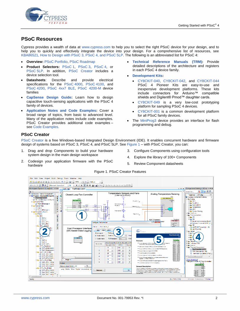
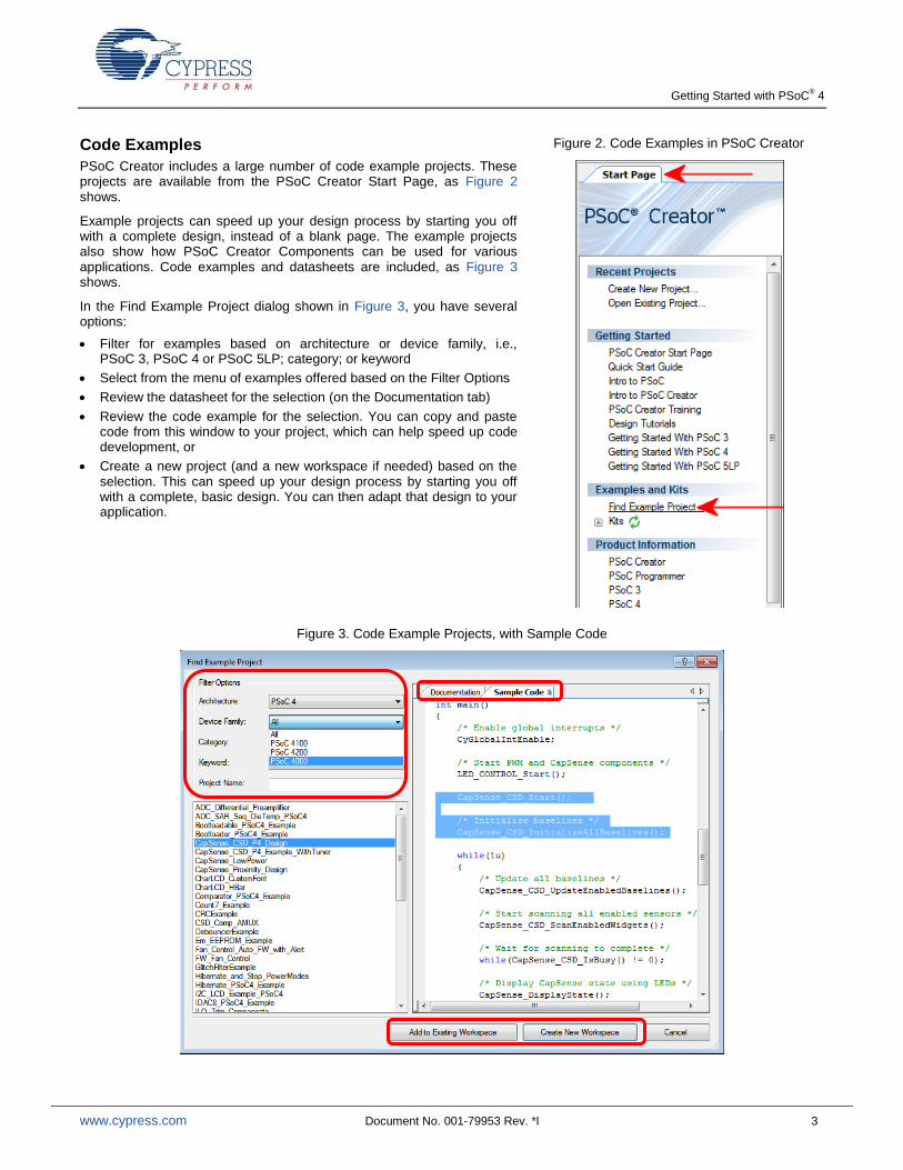
Code Examples
PSoC Creator includes a large number of code example projects. These projects are available from the PSoC Creator Start Page, as Figure 2 shows.
Example projects can speed up your design process by starting you off with a complete design, instead of a blank page. The example projects also show how PSoC Creator Components can be used for various applications. Code examples and datasheets are included, as Figure 3 shows.
In the Find Example Project dialog shown in Figure 3, you have several options:
Filter for examples based on architecture or device family, i.e., PSoC 3, PSoC 4 or PSoC 5LP; category; or keyword
Select from the menu of examples offered based on the Filter Options
Review the datasheet for the selection (on the Documentation tab)
Review the code example for the selection. You can copy and paste code from this window to your project, which can help speed up code development, or
Create a new project (and a new workspace if needed) based on the selection. This can speed up your design process by starting you off with a complete, basic design. You can then adapt that design to your application.
Figure 2. Code Examples in PSoC Creator
Figure 3. Code Example Projects, with Sample Code

Getting Started with PSoC® 4
www.cypress.com Document No. 001-79953 Rev. *I 4
PSoC Creator Help
Visit the PSoC Creator home page to download the latest version of PSoC Creator. Then, launch PSoC Creator and navigate to the following items:
Quick Start Guide: Choose Help > Documentation > Quick Start Guide. This guide gives you the basics for developing PSoC Creator projects.
Simple Component example projects: Choose File > Open > Example projects. These example projects demonstrate how to configure and use PSoC Creator Components.
Starter designs: Choose File > New > Project > PSoC 4 Starter Designs. These starter designs demonstrate the unique
features of PSoC 4.
System Reference Guide: Choose Help > System Reference > System Reference Guide. This guide lists and describes the system functions provided by PSoC Creator.
Component datasheets: Right-click a Component and select “Open Datasheet.” Visit the PSoC 4 Component Datasheets page for a list of all PSoC 4 Component datasheets.
Document Manager: PSoC Creator provides a document manager to help you to easily find and review document resources. To open the document manager, choose the menu item Help > Document Manager.
Technical Support
If you have any questions, our technical support team is happy to assist you. You can create a support request on the Cypress Technical Support page.
If you are in the United States, you can talk to our technical support team by calling our toll-free number: +1-800-541-4736. Select option 8 at the prompt.
You can also use the following support resources if you need quick assistance.
Self-help
Local Sales Office Locations

Getting Started with PSoC® 4
www.cypress.com Document No. 001-79953 Rev. *I 5
PSoC 4 Feature Set
PSoC 4 has an extensive set of features, which include a CPU and memory subsystem, a digital subsystem, an analog subsystem, and system resources, as Figure 4 shows. The following sections give brief descriptions of each feature. For more information, see the PSoC 4 family device datasheets, technical reference manuals (TRMs), and application notes listed previously.
Figure 4 shows the features available in the PSoC 4200-M device family. Depending on the device, all or a subset of these features may be available. Refer to the PSoC 4 product selector guide for details.
Figure 4. PSoC 4 Architecture (PSoC 4200-M)
Peripherals
PSoC 4200M
32-bit
AHB-Lite
CPU Subsystem
Peripheral Interconnect (MMIO)
SRAM
16 kB
SRAM Controller
ROM
8 kB
ROM Controller
FLASH
128 kB
Read Accelerator
SPCIF
Programmable
Digital
UDB UDB
IO Subsystem
CTBm
2x OpAmp
x2
SAR ADC
(12-bit)
x1
Programmable
Analog
IOS
S G
PIO
(8
x p
ort
s)
55 GPIO
4x S
CB
-I2
C/S
PI/U
AR
T
Deep SleepHibernate
Active/Sleep
System Resources
Power
Clock
WDTILO
Reset
Clock Control
DFT LogicTest
IMO
DFT Analog
Sleep Control
PWRSYSREFPOR LVD
NVLatches
BOD
WIC
Reset ControlXRES
PCLK
System Interconnect (Single Layer AHB)
SWD/TC
NVIC, IRQMX
Cortex
M0
48 MHzFAST MUL
2x C
ap
Se
nse
2x L
P C
om
pa
rato
rSMX
LC
D
Port Interface & Digital System Interconnect (DSI)
High Speed I/O Matrix
x4
...
Power Modes
DataWire/
DMA
Initiator/MMIO
2x C
AN
8x T
CP
WM
WC
O
32-bit MCU Subsystem
48-MHz ARM Cortex-M0 CPU with single-cycle multiply
Up to 128 KB of flash with Read Accelerator
Up to 16 KB of SRAM
DMA engine
Programmable Digital
Four programmable logic blocks, each with 8 macrocells and an 8-bit datapath (called universal digital blocks or UDBs)
Cypress-provided peripheral component library, user-defined state machines, and Verilog input
Programmable Analog
Four opamps that operate in Deep-Sleep mode at very low current levels
All opamps have reconfigurable high-current pin-drive, high-bandwidth internal drive, ADC input buffering, and comparator modes with flexible connectivity allowing input connections to any pin
Four current DACs (IDACs) for general-purpose or capacitive sensing applications on any pin

Getting Started with PSoC® 4
www.cypress.com Document No. 001-79953 Rev. *I 6
Two low-power comparators that operate in Deep-Sleep mode
12-bit SAR ADC with 1-Msps conversion rate
Low-Power 1.71-V to 5.5-V Operation
20-nA Stop Mode with GPIO pin wakeup
Hibernate and Deep-Sleep modes allow wakeup-time versus power trade-offs
Capacitive Sensing
Cypress Capacitive Sigma-Delta (CSD) technique provides best-in-class SNR (>5:1) and water tolerance
Cypress-supplied software Component makes capacitive sensing design easy
Automatic hardware tuning (SmartSense™)
Segment LCD Drive
LCD drive supported on all pins (common or segment)
Operates in Deep-Sleep mode with four bits per pin memory
Serial Communication
Four independent run-time reconfigurable serial communication blocks (SCBs) with reconfigurable I
2C, SPI, or UART functionality
Two independent CAN blocks for industrial and automotive networking
Timing and Pulse-Width Modulation
Eight 16-bit timer/counter pulse-width modulator (TCPWM) blocks
Center-aligned, Edge, and Pseudo-random modes
Comparator-based triggering of Kill signals for motor drive and other high-reliability digital logic applications
Up to 55 programmable GPIOs
GPIO pins can be CapSense, LCD, analog, or digital
Drive modes, strengths, and slew rates are programmable

Getting Started with PSoC® 4
www.cypress.com Document No. 001-79953 Rev. *I 7
PSoC is More Than an MCU
Figure 5 shows that a typical MCU contains a CPU (such as 8051 or an ARM Cortex) with a set of peripheral functions such as ADCs, DACs, UARTs, SPIs, and general I/O, all linked to the CPU’s register interface. Within the MCU, the CPU is the “heart” of the device – the CPU manages everything from setup to data movement to timing. Without the CPU, the MCU cannot function.
Figure 6 shows that PSoC is quite different. With PSoC, the CPU, analog, digital, and I/O are equally important resources in a programmable system. It is the system’s interconnect and programmability that is the heart of PSoC – not the CPU. The peripheral analog and digital are interconnected with a highly configurable matrix of signal and data bus meshing that allows you to create custom designs that meet your application requirements. You can program PSoC to emulate an MCU, but you cannot program an MCU to emulate PSoC.
Figure 5. Block Diagram of a Typical MCU
Figure 6. PSoC Block Diagram
A typical MCU requires CPU firmware to process state machines, use a timer for timing, and drive an output pin. Thus, the functional path is almost always through the CPU. However, with PSoC, asynchronous parallel processing is possible. You can configure a PSoC to have elements that operate independently from the CPU. The projects included with this application note demonstrate this concept. The PSoC is configured to make an LED blink without writing any code for the CPU.
As another example, Figure 6 shows that some PSoC devices do not have a UART. However, if the application requires a UART, you can make as many as you need within the configurable logic provided in the digital system by using the predesigned and pretested UART Component in PSoC Creator.
ARM
UART
SPI
I2C
ADC
DAC
PWMTimer
Port A Port B
Port C Port D
Digital System(w/ Programmable Logic)
8051
Analog System
Ge
n I/O
Ge
n I/O
Ge
n I
/O
Ge
n I/O
Ge
n I/O
Ge
n I/O
Gen I/O Gen I/O
Gen I/O Gen I/O
System Interconnect
CPU
ARM Cortex-M0

Getting Started with PSoC® 4
www.cypress.com Document No. 001-79953 Rev. *I 8
My First PSoC 4 Design
This section does the following:
Demonstrates how PSoC can be programmed to do more than a traditional MCU
Shows how to build a simple PSoC design and install it in a development kit
Provides detailed steps that make it easy to learn PSoC design techniques and how to use the PSoC Creator IDE
Note Testing this design requires CY8CKIT-040, CY8CKIT-042, or CY8CKIT-044, which contain an integrated programmer. If you are using CY8CKIT-049, which contains a USB-serial bootloader instead of a programmer, evaluate the code examples provided with the kit instead of this design. See the “Code Examples” section in the kit guide for details. Go to the CY8CKIT-049 kit webpage to download kit guide and code examples.
If you don’t want to go through the design process, you can get the completed PSoC Creator project at http://www.cypress.com/go/AN79953. You can then jump to the Build and Program steps.
About the Design
This design simply blinks two LEDs using a TCPWM Component, as Figure 7, a PSoC Creator schematic, shows. The TCPWM is configured in PWM mode. The two complementary outputs of this PWM control the LEDs. The PWM operates at a very low frequency and 50 percent duty cycle so that the toggling of the LEDs is visible. If you use a dual-color LED instead of two separate LEDs, this project can toggle the color of the dual-color LED.
Figure 7. My First PSoC 4 Design
Part 1: Create the Design
This section takes you on a step-by-step guided tour of the design process. It starts with creating an empty project and guides you through hardware and firmware design entry.
1. Download and install PSoC Creator from the PSoC Creator home page. Note that the installation of the toolset may take a long time – see the PSoC Creator Release Notes for more information.
2. Start PSoC Creator, and from the File menu choose New > Project, as Figure 8 shows.
Figure 8. Creating a New Project

Getting Started with PSoC® 4
www.cypress.com Document No. 001-79953 Rev. *I 9
3. Select Empty PSoC 4 Design, and give the project a name such as “My_First_Project,” as Figure 9 shows. Choose an appropriate location for your new project, and click OK.
Figure 9. Create a New Empty PSoC 4 Project
4. Select the PSoC 4 device that you want to use. Go to Project > Device Selector and select the device. If you are using a
development kit, read the part number from the kit or refer to the kit user guide for the part number. Figure 10 shows an example selection for the CY8CKIT-042 PSoC 4 Pioneer Kit.
Figure 10. Device Selection

Getting Started with PSoC® 4
www.cypress.com Document No. 001-79953 Rev. *I 10
5. Creating a new project generates a project folder with a baseline set of files shown in the Workspace Explorer (see Figure 11). Open the project schematic file TopDesign.cysch by double-clicking it.
Figure 11. Opening TopDesign Schematic
6. Drag one PWM (TCPWM mode) Component from the Component Catalog onto the schematic, as Figure 12 shows.
Figure 12. Location of the PWM Component

Getting Started with PSoC® 4
www.cypress.com Document No. 001-79953 Rev. *I 11
7. Double-click the PWM Component on the schematic to configure the Component properties, as Figure 13 shows. Click the PWM tab, and set the Period value to 254 and the Compare value to 127 to generate a PWM signal with a 50 percent duty cycle.
Set the Prescaler to 8x, to divide the input clock frequency by 8.
Figure 13. Configuring the PWM Component
8. A PWM Component requires an input clock for its operation. Drag and drop a Clock Component onto the schematic, and configure the Frequency to 800 Hz, as Figure 14 and Figure 15 show.
Since the Prescaler value set in PWM Component is 8, the effective input clock of the PWM is only 100 Hz. Therefore, the PWM period of 254 results in a PWM output time period of 2.54 seconds.
Figure 14. Location of the Clock Component

Getting Started with PSoC® 4
www.cypress.com Document No. 001-79953 Rev. *I 12
Figure 15. Configuring the Clock Component
9. Drag and drop a Digital Output Pin Component. Change the name to LED_1 as Figure 16 and
Figure 17 show. Add another Digital Output Pin Component and change its name to LED_2.
Figure 16. Location of the Digital Output Pin Component

Getting Started with PSoC® 4
www.cypress.com Document No. 001-79953 Rev. *I 13
Figure 17. Renaming a Pin Component
10. In the schematic window, select the wire tool, as Figure 18 shows, or press “W.”
Figure 18. Selecting the Wire Tool
11. Wire the Components together, as Figure 19 shows.
Figure 19. Wiring the Schematic

Getting Started with PSoC® 4
www.cypress.com Document No. 001-79953 Rev. *I 14
12. Most Components are disabled at device reset (the major exception being the Clock Component, which is automatically started as a default), and you must add code to the project to enable them. Open main.c from Workspace Explorer and
add code to the main() function, as Code 1 shows.
Code 1. Enabling the PWM Component
int main()
{
/* Enable and start the PWM */
PWM_1_Start();
for(;;)
{
}
}
13. Select Build My_First_Project from the Build menu. Notice in the Workspace Explorer window that PSoC Creator
automatically generates source code files for the PWM, Clock, and Digital Output Pin Components, as Figure 20 shows.
Figure 20. Generated Source Files

Getting Started with PSoC® 4
www.cypress.com Document No. 001-79953 Rev. *I 15
14. Open the file My_First_Project.cydwr (Design-Wide Resource file) from Workspace Explorer and click the Pins tab. You
can use this tab to select the device pins for the outputs LED_1 and LED_2.
Figure 21 shows the pin configuration to connect the LED_1 and LED_2 pins to the green and red LEDs in the CY8CKIT-042 PSoC 4 Pioneer Kit.
Figure 21. Pin Selection
If you’re using CY8CKIT-044, you can connect LED_1 and LED_2 to pins P0[6] and P2[6].
PSoC 4000 parts have fixed pins for complementary PWM outputs – P1[1] and P1[6]. You can not use any other pins for PWM outputs. Refer to the device datasheet for more details. If you are using the CY8CKIT-040, you can use the green LED connected to P1[1], as LED1. To use the red LED as LED2, connect P3[2] from header J4 to P1[6] from header J3, using a wire. You can also connect an external LED to P1[6] as LED2.
If you are using your own board, choose a convenient pin assignment, and then connect external LEDs to the selected pins, as Figure 7 on page 8 shows.
15. Finally, rebuild the project as Step 13 explains.

Getting Started with PSoC® 4
www.cypress.com Document No. 001-79953 Rev. *I 16
Part 2: Program the Device
This section shows how to program the device. If you are using CY8CKIT-040, CY8CKIT-042, or CY8CKIT-044, connect the kit board to your computer using the USB cable. If you are using CY8CKIT-049, see the "Code Examples" section of the kit guide for example projects.
If you are developing on your own hardware, you need a hardware debugger, for example, a Cypress CY8CKIT-002 MiniProg3.
1. Select the PSoC Creator menu item Debug > Select Debug Target, as Figure 22 shows.
Figure 22. Selecting Debug Target
2. In the Select Debug Target dialog box, click Port Acquire, and then click Connect, as Figure 23 shows. Click OK to
close the dialog box.
Figure 23. Connecting to a Device
3. Choose the menu item Debug > Program to program the device with the project, as Figure 24 shows.
Figure 24. Programming the Device
4. You can view the programming status on the status bar (lower-left corner of the window), as Figure 25 shows,
Figure 25. Programming Status
5. After the device is programmed, verify the operation of the project by viewing the toggling of the LEDs.

Getting Started with PSoC® 4
www.cypress.com Document No. 001-79953 Rev. *I 17
Summary
This application note explored the PSoC 4 architecture and development tools. PSoC 4 is a truly programmable embedded system-on-chip, integrating configurable analog and digital peripheral functions, memory, and an ARM Cortex-M0 microcontroller on a single chip. Because of the integrated features and low-leakage power modes, PSoC 4 is an ideal choice for low-power and cost-effective embedded systems.
This application note also guided you to a comprehensive collection of resources to accelerate in-depth learning about PSoC 4.
About the Authors
Name: Nidhin M S
Title: Applications Engineer Sr.
Background: Nidhin graduated from GEC Thrissur with a Bachelor's degree in Electronics and Communication Engineering. His technical interests are analog signal processing, low-power design, and capacitive touch sensing.
Name: Ronny Liu
Title: Applications Manager Sr.
Background: MSEE, Chinese Academy of Science

Getting Started with PSoC® 4
www.cypress.com Document No. 001-79953 Rev. *I 18
Document History
Document Title: Getting Started with PSoC® 4 – AN79953
Document Number: 001-79953
Revision ECN Orig. of Change
Submission Date
Description of Change
** 3881879 RLIU 01/24/2013 New Application Note
*A 3968932 RLIU 04/11/2013 Demo project changed to leverage Pioneer kit
Added architecture introduction
*B 3996226 MKEA 05/09/2013 Reformatted graphics. Updated links
*C 4219723 NIDH 12/19/2013
Updated attached Associated Project files
Updated content across the entire document
Updated in new template
*G 4339565 NIDH 04/10/2014 Updated the projects and the respective section in the AN to support PSoC Creator 3.0 SP1 and PSoC 4000 device
*H 4514729 MKEA 09/25/2014 Added Code Examples section
Minor edits and format changes throughout
*I 4679544 NIDH 03/17/2015
Added More Information section
Removed detailed feature descriptions
Updated for PSoC 4200-M family of devices

Getting Started with PSoC® 4
www.cypress.com Document No. 001-79953 Rev. *I 19
Worldwide Sales and Design Support
Cypress maintains a worldwide network of offices, solution centers, manufacturer’s representatives, and distributors. To find the office closest to you, visit us at Cypress Locations.
Products
Automotive cypress.com/go/automotive
Clocks & Buffers cypress.com/go/clocks
Interface cypress.com/go/interface
Lighting & Power Control cypress.com/go/powerpsoc cypress.com/go/plc
Memory cypress.com/go/memory
PSoC cypress.com/go/psoc
Touch Sensing cypress.com/go/touch
USB Controllers cypress.com/go/usb
Wireless/RF cypress.com/go/wireless
PSoC® Solutions
psoc.cypress.com/solutions
PSoC 1 | PSoC 3 | PSoC 4 | PSoC 5LP
Cypress Developer Community
Community | Forums | Blogs | Video | Training
Technical Support
cypress.com/go/support
PSoC is a registered trademark and PSoC Creator is a trademark of Cypress Semiconductor Corp. All other trademarks or registered trademarks referenced herein are the property of their respective owners.
Cypress Semiconductor 198 Champion Court San Jose, CA 95134-1709
Phone : 408-943-2600 Fax : 408-943-4730 Website : www.cypress.com
© Cypress Semiconductor Corporation, 2013-2015. The information contained herein is subject to change without notice. Cypress Semiconductor Corporation assumes no responsibility for the use of any circuitry other than circuitry embodied in a Cypress product. Nor does it convey or imply any license under patent or other rights. Cypress products are not warranted nor intended to be used for medical, life support, life saving, critical control or safety applications, unless pursuant to an express written agreement with Cypress. Furthermore, Cypress does not authorize its products for use as critical components in life-support systems where a malfunction or failure may reasonably be expected to result in significant injury to the user. The inclusion of Cypress products in life-support systems application implies that the manufacturer assumes all risk of such use and in doing so indemnifies Cypress against all charges. This Source Code (software and/or firmware) is owned by Cypress Semiconductor Corporation (Cypress) and is protected by and subject to worldwide patent protection (United States and foreign), United States copyright laws and international treaty provisions. Cypress hereby grants to licensee a personal, non-exclusive, non-transferable license to copy, use, modify, create derivative works of, and compile the Cypress Source Code and derivative works for the sole purpose of creating custom software and or firmware in support of licensee product to be used only in conjunction with a Cypress integrated circuit as specified in the applicable agreement. Any reproduction, modification, translation, compilation, or representation of this Source Code except as specified above is prohibited without the express written permission of Cypress. Disclaimer: CYPRESS MAKES NO WARRANTY OF ANY KIND, EXPRESS OR IMPLIED, WITH REGARD TO THIS MATERIAL, INCLUDING, BUT NOT LIMITED TO, THE IMPLIED WARRANTIES OF MERCHANTABILITY AND FITNESS FOR A PARTICULAR PURPOSE. Cypress reserves the right to make changes without further notice to the materials described herein. Cypress does not assume any liability arising out of the application or use of any product or circuit described herein. Cypress does not authorize its products for use as critical components in life-support systems where a malfunction or failure may reasonably be expected to result in significant injury to the user. The inclusion of Cypress’ product in a life-support systems application implies that the manufacturer assumes all risk of such use and in doing so indemnifies Cypress against all charges. Use may be limited by and subject to the applicable Cypress software license agreement.