Getting Started with Digi-Cell V2 - 04 - eSTOREd'utilisation/quescom20.… · Getting started with...
55
Getting started with Digi-Cell V2 Hardware install and administrator guide May 2010
Transcript of Getting Started with Digi-Cell V2 - 04 - eSTOREd'utilisation/quescom20.… · Getting started with...

Getting started with Digi-Cell V2
Hardware install and administrator guide May 2010

© QuesCom Page 2/55
Copyright Notice
Copyright Notice
© 1998-2010 Copyright QuesCom
BP 327, 06906 Sophia-Antipolis Cedex, FRANCE
Edited in France, May 2010
All rights reserved. This product and its related documentation are protected by copyright and distributed under QuesCom licenses to its authorized users only. Authorized users who have purchased one or more QuesCom products described herein can download and print a copy of this publication.
No part of this product or its related documentation may be reproduced, adapted or translated without prior written authorization of QuesCom. The information contained herein is subject to change without prior notice.
QuesCom Headquarters – Sophia Antipolis - France BP 327 06906 Sophia-Antipolis Cedex FRANCE
Phone: +33 4 97 23 48 48 Fax: +33 4 97 23 48 49 URL: http://www.quescom.com E-mail: [email protected]
QuesCom South Africa Worcester House Eton Office Park West Cnr Sloane & Harrison Street Epsom Downs Phone: +27 11 300 1 300 Fax: +27 11 300 1 301

© QuesCom Page 3/55
Trademarks
Trademarks
QuesCom®, NextBX® and SmartIAD® are registered trademarks of QuesCom SA.
Microsoft®, MS-DOS®, Windows®, and Windows NT® are registered trademarks of Microsoft Corporation.
UC500 is registered trademark of Cisco Corporation.
All other products mentioned herein may be trademarks or registered trademarks of their respective companies and are hereby acknowledged.

© QuesCom Page 4/55
Disclaimer
Disclaimer
Information contained herein supersedes preliminary specifications or data sheets of the product as well as earlier versions of this publication, if any.
While every effort has been made to ensure the accuracy of this publication, QuesCom assumes no liability for omissions or editorial errors contained herein. QuesCom reserves the right to revise the information herein at any time without prior notice. Changes and improvements will be incorporated into the new version of this publication.
THIS PUBLICATION IS PROVIDED “AS IS” WITHOUT WARRANTY OF ANY KIND. QUESCOM HEREBY DISCLAIMS ALL WARRANTIES, EITHER EXPRESS OR IMPLIED, INCLUDING BUT NOT LIMITED TO, ALL WARRANTIES OF MERCHANTABILITY, FITNESS FOR A PARTICULAR PURPOSE, AND THOSE ARISING FROM A COURSE OF DEALING, USAGE OR TRADE PRACTICE.
IN NO EVENT SHALL QUESCOM BE LIABLE FOR ANY INDIRECT, SPECIAL, CONSEQUENTIAL OR INCIDENTAL DAMAGES, INCLUDING BUT NOT LIMITED TO, ALL DAMAGES RESULTING FROM LOSS OF USE, DATA OR PROFITS ARISING OUT OF THE USE OF OR INABILITY TO USE THIS PRODUCT, EVEN IF ADVISED OF THE POSSIBILITY OF SUCH DAMAGES.

© QuesCom Page 5/55
C o n t e n t s
About This Document 6
Customer Service 8
1. Product description 9
2. Preparing Your Installation 11
2.1. Safety Information 11 2.1.1. Electrical Safety 12 2.1.2. Prevention of Electrostatic Discharge 13
2.2. General Requirement 13 2.2.1. Power Supply 13 2.2.2. Site Environment 14 2.2.3. Waste Recycling 14
2.3. Unpacking QuesCom Digi-Cell V2 15
3. Connecting QuesCom Digi-Cell V2 Hardware 17
3.1. Connecting overview 17 3.2. SIM Card Installation 18 3.3. Antenna Connection 19 3.4. PBX connection 19 3.5. Mounting 20 3.6. Power Connection 21 3.7. Check the Digi Cell ready 22
4. Digi-Cell advance configuration 23
4.1. Download and install the Maintenance program and the USB driver 24 4.2. Start the Digi-Cell Maintenance and configure communication settings 26 4.3. Load Digi-cell settings into the maintenance program 27 4.4. Setup panel settings 28 4.5. Call back configuration panel 31 4.6. SMS configuration panel 33 4.7. Connect configuration panel 36 4.8. Security configuration panel 38 4.9. Alarms configuration panel 39 4.10. Dual SIM configuration panel 40 4.11. Call cut configuration panel 41 4.12. Monitor configuration panel 42 4.13. Profiles configuration panel 45 4.14. Events configuration panel 46 4.15. Firmware upgrade 47
5. Digi-Cell basic configuration 49
5.1. SMS Programming 49 5.2. DTMF Programming 50
6. LCD Interface & LED 53
7. Technical Specification 55

About This Document
© QuesCom Page 6/55
A b o u t T h i s D o c u m e n t
Document purpose
This document describes how to perform the hardware connection of a QuesCom Digi-Cell V2 gateways, how to call with the QuesCom Digi-Cell V2 and how to use the administration interface.
Audience
This document is intended for experienced technicians, service representatives, and other persons trained to install software programs of telecommunication systems. Such persons are expected to have sufficient knowledge of computing and network in order to take suitable safety precautions while configuring the software program described herein.
Structure
This document is organized in the following structure:
Chapter 1 provides an overview of the Digi-Cell V2 product
Chapter 2 describes how to prepare the installation
Chapter 3 describes how to connect the Digi-Cell V2
Chapter 4 describes how to install and use the Digi-Cell Maintenance program
Chapter 5 describes how to configure the Digi-Cell by SMS or by DTMF
Chapter 6 describes how to use the LCD interface
Chapter 7 provides Digi-Cell Technical Specifications

About This Document
© QuesCom Page 7/55
Convention
This document applies the following typographic conventions:
Reminder
Note
A note provides additional or complementary information on a particular subject.
Caution
A caution gives important instructions to be followed. You risk damaging your equipment or losing your data if you do not follow the instructions.
Warning!
A warning calls attention to important alerts that will cause personal injury, health hazard or permanent damage to your equipment if not observed.
Computer Text Computer generated text such as program code or command prompt is shown in Courier font.
Dialog/Menu/Button Windows, dialogs, menus or buttons of a computer program are printed in bold.
Feedbacks
QuesCom is committed to providing documentation that matches your expectations. We welcome any feedback, question or suggestion to help us improve our documentation quality.
Please send your comments to [email protected] together with the document title and number as indicated on the cover page of this document.

Customer Service
© QuesCom Page 8/55
C u s t o m e r S e r v i c e
Purchase from QuesCom
For any products purchased directly from QuesCom, contact QuesCom Customer Service should you need further assistance (please kindly have your customer ID and product serial number ready):
Customer Service
Phone : +27 11 300 1300
Facsimile: +27 11 300 1301
E-mail: [email protected]
URL: http://support.quescom.com/
Purchase from Retailer
For any products purchased from a retailer or distributor, contact your respective retailer or distributor should you have any questions regarding the product received or need further technical assistance.

Preparing your installation
© QuesCom Page 9/55
1 . P r o d u c t d e s c r i p t i o n
Model
The QuesCom Digi-Cell V2 Gateway is an analog – GSM gateway, connecting:
• a FXO port of one analog line of a PBX
• to the GSM network
• thanks to one SIM card inserted into the appliance
Calls can be then routed to different GSM networks thanks to PBX routing capabilities.
Communication ports
In addition to GSM and analog communicating ports, all Digi-Cell V2 are also supplied with a Universal Serial Bus (USB) port connection for SMS on desktop features, firmware update and administration settings.
Front panel
Figure 1-1 shows the front panel of the Digi-Cell V2 Gateway:
Figure 1-1 Front Panel of Digi-Cell V2 Gateway

Preparing your installation
© QuesCom Page 10/55
Rear panel
Figure 1-2 shows the rear panel of a typical Digi-Cell V2 Gateway:
Figure 1-2 Rear Panel of Digi-Cell V2 Gateway
Power connector Coaxial connectorfor GSM antenna
SIM tray

Preparing your installation
© QuesCom Page 11/55
2 . P r e p a r i n g Y o u r I n s t a l l a t i o n
Overview
This chapter provides important information that you must be acquainted with before installing the Digi-Cell V2 Gateway.
2.1. Safety Information
Introduction
Important safety information is highlighted throughout this document whenever applicable. You risk serious danger, personal injury, health hazard, or permanent equipment damage if this information is not followed, understood or performed correctly.
A warning symbol precedes each warning statement as shown below:
Warning!
Content of the warning.
Safety information
For your protection, observe the following safety precautions when installing or working on your product or equipment:
Read and understand thoroughly all instructions provided in the documentation that comes along with your equipment before you handle it.
Pay extra attention to all warnings and cautions highlighted in the documentation or indicated on the equipment.
Get well informed about hazards that can be caused by electrical circuitry and appliances.
Be familiar with standard practices to prevent accidents that could occur during electrical or mechanical work.
Never install or use the equipment near wet area or with wet hands or tools.
Never install or use the equipment in an unprotected location that could trip others up.
Always keep your equipment in a clear, dry, and dust-free location.
Avoid wearing loose or dangly clothing such as ties or scarves while working with the equipment.
Wear safety glasses when working under conditions that could be hazardous to your eyes.
Do not act recklessly to cause hazards to others or the environment while handling the equipment.
Preparing your installation
© QuesCom Page 12/55
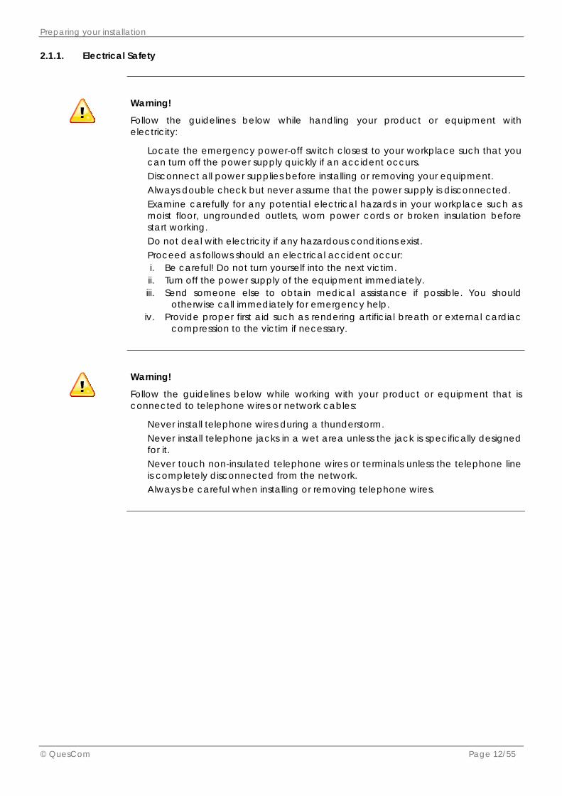
2.1.1. Electrical Safety
Warning!
Follow the guidelines below while handling your product or equipment with electricity:
Locate the emergency power-off switch closest to your workplace such that you can turn off the power supply quickly if an accident occurs.
Disconnect all power supplies before installing or removing your equipment. Always double check but never assume that the power supply is disconnected. Examine carefully for any potential electrical hazards in your workplace such as
moist floor, ungrounded outlets, worn power cords or broken insulation before start working.
Do not deal with electricity if any hazardous conditions exist. Proceed as follows should an electrical accident occur:
i. Be careful! Do not turn yourself into the next victim. ii. Turn off the power supply of the equipment immediately. iii. Send someone else to obtain medical assistance if possible. You should
otherwise call immediately for emergency help. iv. Provide proper first aid such as rendering artificial breath or external cardiac
compression to the victim if necessary.
Warning!
Follow the guidelines below while working with your product or equipment that is connected to telephone wires or network cables:
Never install telephone wires during a thunderstorm. Never install telephone jacks in a wet area unless the jack is specifically designed
for it. Never touch non-insulated telephone wires or terminals unless the telephone line
is completely disconnected from the network. Always be careful when installing or removing telephone wires.

Preparing your installation
© QuesCom Page 13/55
2.1.2. Prevention of Electrostatic Discharge
Overview
Electrostatic discharge (ESD) can damage your equipment and impair its electrical circuitry. An ESD event can occur if the electronic printed circuit boards are improperly handled. This can consequently cause complete or intermittent failures to your equipment.
Always observe the following procedures to prevent ESD when replacing or removing modules in your equipment:
Make sure the chassis of your equipment is electrically connected to earth ground. Wear an anti-static wrist strap with a good skin contact. Connect the strip clip to an
unpainted surface of the chassis in order to channel unwanted ESD voltages safely to ground.
Caution
For your equipment safety, verify periodically that the resistance value of the anti-static wrist strap always falls between 1 and 10 mega ohm (MΩ).
2.2. General Requirement
Overview
This section describes the general requirements that your selected site must meet in order to install and operate the Digi-Cell V2 Gateway safely.
2.2.1. Power Supply
Noise-free
Make sure the power supply at your selected site is noise-free without spikes. A power conditioner is recommended to maintain a smooth power supply if necessary. The Digi-Cell V2 gateway must absolutely be connected to grounded power outlets.

Preparing your installation
© QuesCom Page 14/55
2.2.2. Site Environment
Installation
The Digi-Cell V2 Gateway can be placed on a stable surface in your selected site such as a desktop, shelf or rack. The layout of your site makes a major contribution to proper system operation. Efficient room wiring, adequate ventilation, ample space between appliances and easy equipment access are among the key factors determining satisfactory system performance and maintenance.
The installation site should meet the minimum requirements listed hereafter to provide an acceptable operating environment for the Digi-Cell V2 Gateway:
Air Ventilation
Your gateway dissipates heat just as any other electrical equipment does. The ambient temperature may not be enough to cool the gateway down to an acceptable operating temperature. Make sure your installation site sustain sufficient air ventilation for this purpose. In addition, your gateway chassis must always be well fastened to allow efficient air-cooling within the equipment. An open chassis permits air leaking that may interrupt the internal air-cooling.
Prevention of Electrostatic Discharge
Always respect the procedure given in Section 2.1.2 to avoid immediate or intermittent equipment failures due to electrostatic discharge.
Site Capacity
The installation site should provide enough space to accommodate all necessary equipment and accessories. All equipment must be maintained at reasonable distance from each other for air ventilation and easy access.
2.2.3. Waste Recycling
Delivery Package
We strongly recommend our customers to respect waste recycling practices for a better environment.
QuesCom products are delivered in a carton package with protective padding. Keep the delivery package temporarily in case you need to return the product for customer service. Once our product gives you the expected satisfaction, please recycle the delivery package properly.
Used Battery or Obsolete Device
For customers in the European Union, please respect the EU recycling regulation. Please dispose of any removed batteries or obsolete devices at the appropriate recycling center. It is illegal to dispose of such articles in domestic refuse. For customers outside of EU, please observe your local statutory provisions for this subject matter.

Preparing your installation
© QuesCom Page 15/55
2.3. Unpacking QuesCom Digi-Cell V2
Package composition
The delivery package of the Digi-Cell V2 contains:
1. The Digi-Cell V2 2. A bag containing the accessories of the Digi-Cell V2
Hardware Configuration
When you are ready to install the Digi-Cell V2 Gateway, remove all items from the box carefully. Visually inspect all items for any damage or omission before installation.
The hardware configuration of the Digi-Cell V2 Gateway should feature:
1 power connector 1 coaxial connector for GSM antenna 1 SIM connectors 4 LED A numeric display with two white command buttons An USB port Tip &Ring Connector
Accessories
The accessories of the QuesCom Digi-Cell V2 Gateway include:
An AC adaptor with universal compatibility (input of 100V/240V) 1 antennas 1 mounting kit 1 green FXS RJ-45 connector
Note
Please contact your retailer or shipping company should you find any damaged or missing items in your delivery package.
USB cables are not supplied in the pack

Preparing your installation
© QuesCom Page 16/55
Accessories
The AC adapter:
Antenna
Mounting kit
Tip and Ring to RJ 11 connector
Antenna SMA Male Connector

Chapter 3 - Connecting QuesCom Digi-Cell V2 Hardware
© QuesCom Page 17/55
3 . C o n n e c t i n g Q u e s C o m D i g i - C e l l V 2 H a r d w a r e
3.1. Connecting overview
Overview
This chapter provides step-by-step instructions to install the hardware of Digi-Cell V2 Gateway. Read and understand the instructions thoroughly in order to install your equipment in the safest manner.
Connection drawing
Following sections describes how to connect phone, power cables, GSM antennas, Ethernet and USB cable as shown in the drawing below:
Connecting steps
The table below sum up required steps to connect the Digi-Cell V2 gateway:
Steps Description
1 Disable SIM PIN code
2 Insert SIM card into SIM tray
3 Connect the antenna
4 Connect to the PABX
5 Mount the unit
6 Connect the power supply
7 Check the gateway is ready
USB
Antenna
Power supply
Analog port of the PABX

Chapter 3 - Connecting QuesCom Digi-Cell V2 Hardware
© QuesCom Page 18/55
3.2. SIM Card Installation
Prepare SIM card
SIM PIN code must be disabled before being inserted into the appliance. Using a mobile phone, disable the PIN of the SIM card to be used.
Procedure to insert SIM card
Follow the steps described hereafter to install a SIM card in the SIM holder of your QuesCom Digi-Cell V2 Gateway.
Steps Actions
1
Use a pointed device, for instance a pen, to press on the little button
next to the SIM holder (see label 1) The SIM holder will then be ejected (see label 2)
Figure 3-2 Open the SIM Holder
2
Insert your SIM card into the SIM holder (see label 1) Make sure that the golden connector of your SIM card faces down
when inserted into the holder and the angled corner of your SIM card fits into the right place provided (see label 2)
Push back the SIM holder into its slot (see label 3)
Figure 3-3 Installing the SIM Card

Chapter 3 - Connecting QuesCom Digi-Cell V2 Hardware
© QuesCom Page 19/55
3.3. Antenna Connection
Procedure
The GSM port, a dual-band GSM antenna (GSM 900/1800) must be connected to the SMA connector (50Ω, female coaxial jack) located at the rear panel of your Digi-Cell V2 Gateway.
Unwind antenna cable and connect it to the gateway.
Recommended position
Always mount the antenna in a vertical position for the best reception and ensure that it is situated as far as possible from the gateway.
When installing multiple Digi-Cell V2 gateways, antennas must be mounted a minimum distance of 20 cm apart.
Antennas are fitted with magnetic bases and can therefore be mounted on any metal surface onto the metal plate provided.
Ensure that when the metal plate is to be mounted using the provided double-sided tape, that the surface is clean and free from dust and oils.
3.4. PBX connection
Procedure
Follow the instructions below to connect your Digi-Cell V2 Gateway to the PABX:
Steps Actions
1 Connect the PABX port line or key-set to the green Tip/Ring connector (Line polarity does not matter)

Chapter 3 - Connecting QuesCom Digi-Cell V2 Hardware
© QuesCom Page 20/55
3.5. Mounting
Procedure
Mount the gateway using the mounting kit provided.
Note: Multiple may be slotted together for easier installation.

Chapter 3 - Connecting QuesCom Digi-Cell V2 Hardware
© QuesCom Page 21/55
3.6. Power Connection
Read before connecting!
Warning!
• Read all instructions before connecting your Digi-Cell V2 Gateway to power supplies.
• Internal components of Digi-Cell V2 Gateway are pre-installed and pre-configured. Do not remove, replace or modify these components without consulting QuesCom customer service or your retailer/distributor.
You must always respect the electrical safety to protect yourself against electrical accidents once your Digi-Cell V2 Gateway is connected to power supplies.
Never remove the top chassis cover of your Digi-Cell V2 Gateway once it is connected to power supplies.
• Never work on your Digi-Cell V2 Gateway or connect/disconnect any of its system cables during a thunderstorm or lightning storm.
• The plug-socket combination of the power supply for your Digi-Cell V2 Gateway must absolutely be accessible at all times because it serves as the main disconnecting device.
Caution
Never operate your Digi-Cell V2 Gateway without tightly fasten its chassis cover for the reason of having adequate internal air-cooling.
Procedure Follow the instructions below to connect your Digi-Cell V2 Gateway to a power supply:
Steps Actions
1 Make sure that all power outlets are earth grounded with over-current protection.
2 Connect the 12VDC connector of the adapter to the power connector located at the rear panel of your Digi-Cell V2 Gateway.
3 Connect the AC connector of the adapter to a power socket.

Chapter 3 - Connecting QuesCom Digi-Cell V2 Hardware
© QuesCom Page 22/55
3.7. Check the gateway ready
Green LED
The gateway is ready for use once the green ACT LED lights up. The green GSM LED will indicate network connectivity by flashing.

Chapter 4 - Digi-Cell advance configuration
© QuesCom Page 23/55
4 . D i g i - C e l l a d v a n c e c o n f i g u r a t i o n
Overview
For advance programming, a maintenance program can be installed on a workstation. This section describes: • how to install the maintenance program and USB drivers • how to connect the workstation to the Digi-Cell – V2 • how to perform basic setup through this interface • how to update the Digi-Cell firmware

Chapter 4 - Digi-Cell advance configuration
© QuesCom Page 24/55
4.1. Download and install the Maintenance program and the USB driver
Maintenance program
Follow the instructions below to download and install the Digi-Cell Maintenance Program to a workstation.
Steps Actions
1 Connect to http://support.quescom.com. Select Download > Digi-Cell V2 > Maintenance Program V2_8_90 (or later)
2 • Double click on the program
Digi_Cell_V2_8_90_setup.exe • In the Setup box “This will install
Digi-Cell Maintenance” click Next.
• Select the location for install file (the default is C:\Program Files\Innovations\DigiCell) and click Next.
• Select where the installation program must place the Digi-Cell
Maintenance program shortcut and click Next. • Configure additional shortcut and click Next. • If the installation option summary is correct, click Install.
3 In the “Completing the Digi-Cell Maintenance Setup Wizard”, click Finish.
USB Driver Follow the procedure below to install the USB drivers on a workstation, in order to configure the Digi-Cell V2 thanks to the Digi-Cell Maintenance Program through an USB port:
Steps Actions
1 Connect to http://support.quescom.com. Select Download > Digi-Cell V2 > Digi-Cell-USB.zip.
2 • Un Zip Digi-Cell-USB.zip on a workstation. • Double click on CP210xVCPInstaller.exe.
• Click “Change Install location” to modify the install location.
3 Then click Install. A dialog box “Scanning will be opened”. Click OK in the message box “Success”.
Chapter 4 - Digi-Cell advance configuration
© QuesCom Page 25/55
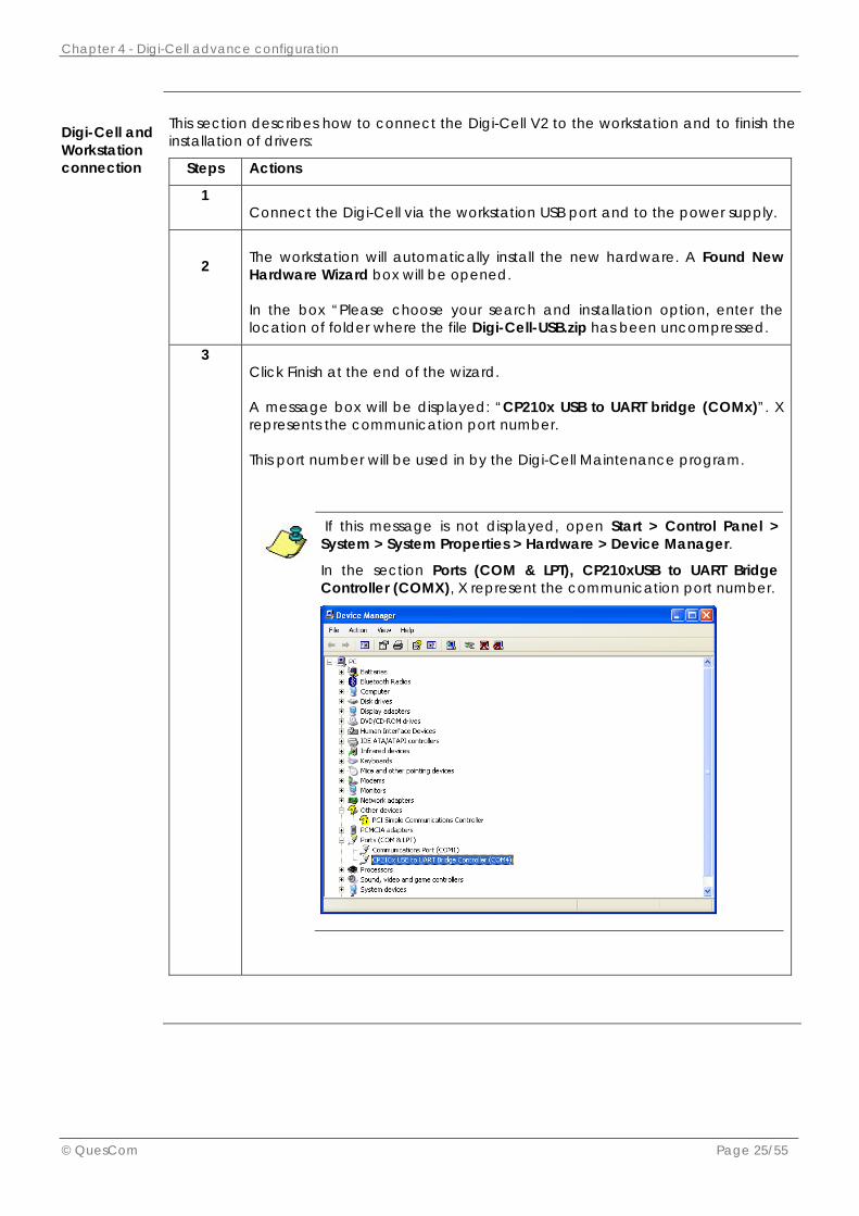
Digi-Cell and Workstation connection
This section describes how to connect the Digi-Cell V2 to the workstation and to finish the installation of drivers:
Steps Actions
1 Connect the Digi-Cell via the workstation USB port and to the power supply.
2 The workstation will automatically install the new hardware. A Found New Hardware Wizard box will be opened.
In the box “Please choose your search and installation option, enter the location of folder where the file Digi-Cell-USB.zip has been uncompressed.
3 Click Finish at the end of the wizard.
A message box will be displayed: “CP210x USB to UART bridge (COMx)”. X represents the communication port number.
This port number will be used in by the Digi-Cell Maintenance program.
If this message is not displayed, open Start > Control Panel > System > System Properties > Hardware > Device Manager.
In the section Ports (COM & LPT), CP210xUSB to UART Bridge Controller (COMX), X represent the communication port number.

Chapter 4 - Digi-Cell advance configuration
© QuesCom Page 26/55
4.2. Start the Digi-Cell Maintenance and configure communication settings
Start the Maintenance Program
Open Start Menu > All Programs > Digi-Cell Maintenance > Digi-Cell Maintenance. The following window will be opened:
Com-munication settings
Communication settings depend on the serial number of your Digi-Cell. The serial number is slicked on the equipment. Note the Baud-Rate corresponding to your equipment.
Serial number Baud-Rate 1005-XXXXXXXXXX 9600 1007-XXXXXXXXXX 9600 1009-XXXXXXXXXX 9600 1107-XXXXXXXXXX 9600 1118-XXXXXXXXXX 19200 1201-XXXXXXXXXX 19200 1401-XXXXXXXXXX 19200 1402-XXXXXXXXXX 19200
Configure com-munication settings
Follow the procedure below to check communication settings between the workstation and the Digi-Cell Maintenance program:
Steps Actions 1 Select Setup > Communication Setup. 2 The following window will be displayed:
• Select Comport = X (the communication port number previously configured)
• Select BaudRate = Value. This value depend on the serial number of your Digi-Cell V2 equipment
• Select CommPort TimeOut = 15
3 Click Close.

Chapter 4 - Digi-Cell advance configuration
© QuesCom Page 27/55
4.3. Load Digi-cell settings into the maintenance program
Load Digi-Cell configuration
Follow the procedure below to load the Digi-Cell configuration into the Digi-Cell Maintenance Program:
Steps Actions
1 Click Setup > Digi-Cell Setup.
2 Select “Read Settings from Digi-Cell” .
The Digi-Cell configuration is now loaded into the Digi-Cell Maintenance Program.

Chapter 4 - Digi-Cell advance configuration
© QuesCom Page 28/55
4.4. Setup panel settings
Overview
The section below describes settings of the setup panel:
Line Reversal Functions
Line reversal is a method of reducing port lock-ups on PBX systems by reversing the polarity of the TIP/RNG signals. It can be programmed to occur when a call is answered and/or when a call is terminated by the remote party. To enable this function set the following values:
Parameter Value At Start 0000 – No line reversal when call answered
0999 – Single line reversal when call answered End call 0000 – No line reversal when call terminated
0999 – Single line reversal when call terminated Line Reversal Timer
Value - Set this value to obtain double line reversal after Value x 100ms. Example: set value = 0010 to obtain a double line reversal with a delay of 1 second between reversals at either the beginning or end of a call
• Line reversal is primarily implemented on Philips PBX systems. Some other manufacturers may also require line reversal and can be confirmed by contacting the vendors of that specific PBX system.
• Note that Line reversal function can be programmed via DTMF tones from a handset plugged into the Digi-Cell unit. Refer to the section DTMF Programming of this document.

Chapter 4 - Digi-Cell advance configuration
© QuesCom Page 29/55
Dial string setup
Dial string setup is a way to determine when to connect the call.
Parameter Value Maximum Dial Digit
The Digi-Cell waits for the number of digits programmed in the “Maximum Dial Digit” field. Once all digits received, the Digi-Cell immediately starts completing the call.
Dial Delay If fewer digits than programmed as above are received, the Digi-Cell waits for the number of seconds as set in the “Dial Delay” field.
• Always ensure that these two settings are correct according to the numbers being dialed by the customer.
• Also inform the customer that they should wait for the predetermined time should they need to phone fewer digits than specified.
• Note that Dial String setup function can be programmed via DTMF tones from a handset plugged into the Digi-Cell unit. Refer to the section DTMF Programming of this document.
Line impedance
The Line Impedance setting is used to match the line synthesis of the Digi-Cell router to that required by the PBX. Under normal circumstances it would be set between 40 and 46 ohm. To adjust the line impedance, set the new impedance value in the field “Value” and press “Change”.
Changes to the Line Impedance should only be changed on advice from a QuesCom support representative.
SLIC & GSM Volume interface
The SLIC volume interface settings are used to change the audio volume levels on both the incoming (IN) and outgoing channels (OUT) individually.
Note that the SLIC Volume interface function can be programmed also:
• via DTMF tones from a handset plugged into the Digi-Cell unit. Refer to the section DTMF Programming of this document.
• With SMS, refer to the section SMS programming of this document
Some older versions of Digi-Cell may enable the option of adjusting the audio levels of the GSM module as well

Chapter 4 - Digi-Cell advance configuration
© QuesCom Page 30/55
Other parameters
Parameter Value Network Lock Status
Not applicable
Loop Current
Not applicable
SIM Swop Timer
Not applicable
Enable Network Barring
The network barring option will limit calls to on-network calls only.
Prime Net Not applicable Allow Incoming Calls
Check to allow incoming calls
Refresh Timer
The Refresh Timer is another mechanism to ensure the router has good signal and also to reduce possible lock-ups by rebooting the router when not in use for this predetermined time. Enter a value in minutes.
About Provide the firmware version
Call Termination (B Party)
Possible parameters are: Parameter Value Engage Tone
Not applicable
Silence Not applicable Line Break Not applicable

Chapter 4 - Digi-Cell advance configuration
© QuesCom Page 31/55
4.5. Call back configuration panel
Overview
Call Back is a feature allows a user of being called back by the Digi-Cell. Can be programmed to dial back all numbers or only listed numbers. A total of 128 numbers can be programmed onto the unit. Unlisted or numbers with CLI disabled will be allowed to dial into the unit and will then be connected to either the PABX or Key-set connected to the Digi-Cell. The snapshot below shows the callback configuration panel:
Options
3 incoming call management can be configured:
Option Description Disable All incoming calls will be passed through to PBX Enable All numbers that phone in with CLI will be phoned back, all other calls will ring
through to PBX Number Enable
Only a list of preset numbers will be phoned back, any other calls/numbers
Always ensure that country code and leading digit is programmed correctly otherwise callback will not function correctly. Do not use the plus “+” sign when entering the country code.
The following options can also be configured:
Parameter Value Country Code
Enter here your country code, ex 33 for France, 27 for South Africa
Leading Digit
Enter the Leading Digit if required (ex: 0 for South Africa)?

Chapter 4 - Digi-Cell advance configuration
© QuesCom Page 32/55
Load Call back numbers
To enter the list of preset callback numbers, click Load Callback Number. This window allows setting up profiles for different customers as well as adding and removing callback numbers. Up to 128 numbers can be configured onto a Digi-Cell router.
To check the current numbers press the Upload button. To program the listed numbers press the Download button.
• Always ensure that you remember to click “Write settings to Digi-Cell” button on maintenance program after downloading the callback numbers to ensure that they are written into the router’s memory.
• Note that adding/removing a number into the callback list can be configured by sending a SMS. Refer to the section SMS programming of this document.

Chapter 4 - Digi-Cell advance configuration
© QuesCom Page 33/55
4.6. SMS configuration panel
Overview
The Digi-Cell SMS functions are: • Send / receive SMS onto a PC thanks to the PC SMS interface. This program can be
downloaded from the QuesCom support web site http://support.quescom.com. • Send status report to up to two different numbers. This feature can be used for
monitoring the routers for billing and health status.
SMS can be sent / received simultaneously with voice traffic.
Once the PC SMS Interface is enabled please note that the Digi-Cell will no longer respond to maintenance SMS sent to it.
Settings
The snapshot below show the SMS configuration panel.

Chapter 4 - Digi-Cell advance configuration
© QuesCom Page 34/55
Maintenance SMS
Settings are described below:
Option Description Report via SMS / report Via Email Not applicable SMS Timer (Hours) Set a value between 1 hour and 48 hour. The unit
will send a SMS every SMS Timer hours. SMS Number 1 & 2 Up to two different numbers can be configured
for sending status reports. Enter the SMS number in International format and click Enable.
Digi Cell SMS Description The SMS Description will be included in status SMS and can be up to 16 characters long.
PC SMS Function The PC SMS function should be enabled if the router is used on a PC to send or receive SMS.
SMS Control Security Number For security up to two control numbers may be programmed onto the router. This will allow only these numbers to be able to alter any settings via SMS. If left blank the Digi-Cell will respond to instructions from any SMS received.
PC SMS Interface
To send and receive SMS from your PC with a Digi-Cell V2, install: • SMS Messenger Ver 1.20.exe or upper version. This software is available on QuesCom
support web site. The snapshot below shows the PC SMS interface panel.

Chapter 4 - Digi-Cell advance configuration
© QuesCom Page 35/55
SMS button: change settings of a remote Digi-Cell
To perform effective remote maintenance you may connect to a Digi-Cell and then click on the “SMS” button which will bring up this screen.
Here you may request and change various settings of a remote Digi-Cell by means of SMS
Once the SMS is sent you must enable the “Receive SMS” and then wait for the remote router to reply. When the reply is received the program will automatically switch off the receive function and update the maintenance display.

Chapter 4 - Digi-Cell advance configuration
© QuesCom Page 36/55
4.7. Connect configuration panel
Overview
Connect settings can be configured through the administration interface:
Connect Tones
This parameter concerns outgoing calls. Connect Tones are audible tones generated by the Digi-Cell to indicate to a caller that calls are connected via the Digi-Cell. Select between:
• Simulated Ring Tone
• Tone on Dial Complete
• Busy tone on Dial Complete
• None tone on Dial Complete
Note that these tones can be configured by sending a SMS to the digi-Cell. Refer to the section SMS programming of this document.
Digits Dial Debug
The DEBUG mode will set the router to transmit more verbose output via serial port in order to debug using terminal emulation programs like HyperTerminal.
DTMF sensitivity
DTMF Sensitivity may be changed to make the Digi-Cell more or less sensitive to DTMF tones received from the PBX.

Chapter 4 - Digi-Cell advance configuration
© QuesCom Page 37/55
Low Signal
The following options can also be configured: Option Description Low Signal Value Low Signal behavior setting is used to determine how
the router will react when the cellular signal drops below a predetermined threshold value. The threshold can be adjusted but you should remember that the value is a value between 0 and 31.
If the signal is lower than the value set. The unit can do one of these options:
• Enable / Disable 48V
• Enable / Disable Dial Tone
• Flash Red LED (Reset Modem)
• Do Nothing
• Always remember to “Write settings to Digi-Cell” to update the settings on the Digi-Cell. If this is not done, any of the settings that were changed will be applied.
• To reset to factory defaults you can press “Default” to bring up the factory settings. You should still write settings to router to apply them.

Chapter 4 - Digi-Cell advance configuration
© QuesCom Page 38/55
4.8. Security configuration panel
Overview
Security settings can be configured through the administration interface:
PIN code
Set SIM PIN characteristics:
Option Description PIN / Enable The SIM PIN code is usually disabled. If you wish to use
the PIN function of the SIM card, enter the PIN code and check Enable.
Check for SIM card on Boot up Check this box and the Digi Cell will check if the SIM PIN code is correct during the reboot.
Password
You may also add password protection to the Digi-Cell. This will force whoever wants to program the unit to enter it otherwise no changes can be made. The password may be altered if required.
Warning!
Please note that the ONLY way to remove a password is by returning the Digi-Cell to QuesCom RSA for re-programming.

Chapter 4 - Digi-Cell advance configuration
© QuesCom Page 39/55
4.9. Alarms configuration panel
Overview
Power alarms are no longer implemented but to ensure downwards compatibility of our maintenance program these values will still be displayed for all routers and will most likely remain part of our maintenance program in the future.

Chapter 4 - Digi-Cell advance configuration
© QuesCom Page 40/55
4.10. Dual SIM configuration panel
Overview
This panel allows disabling SIM CLI sending.
Dual SIM Setup
Deprecated function. In past versions of Digi-Cell you had the option of installing two SIM cards for the purpose of gaining more free minutes. Due to the inherent “down-time” during the change between SIM cards this option is no longer available. It has remained in our maintenance program for downwards compatibility.
Own number sending
Option Description Disable Own Number Sending To disable the SIM sending its CLI. Auto Reboot Digi-Cell To make the effect of the “Disable own number
sending” immediately.

Chapter 4 - Digi-Cell advance configuration
© QuesCom Page 41/55
4.11. Call cut configuration panel
Overview
This panel allows configuring the call cut timer:
Options
Most network operators will cut cellular calls after 60 minutes. Because of this the Digi-Cell has been designed to cut calls after 60 minutes, but this time may be reduced should the user require this.
After 60 minutes the Digi-Cell will enter a “lock-up release” sequence which includes “line-breaks” and “line reversals” in order to release PBX ports in case of a port lock-up on the PBX.

Chapter 4 - Digi-Cell advance configuration
© QuesCom Page 42/55
4.12. Monitor configuration panel
Overview
This panel proposes a variety of preset functions. Note that some functions are GSM module specific and may not function as desired on other GSM modules.
Sections below describe AT Command Macro’s.
Signal Strength
Send the command AT+CSQ, meaning Signal Quality.
Execution command returns received signal strength indication <rssi> and channel bit error rate <ber> from the ME. Test command returns values supported by the TA as compound values.
+CSQ: (list of supported <rssi>s),(list of supported <ber>s) <rssi>: 0 -113 dBm or less 1 -111 dBm 2...30 -109... -53 dBm 31 -51 dBm or greater 99 not known or not detectable <ber>(in percent): 0 <0.01% 1 0.01% --- 0.1% 2 0.1% --- 0.5% 3 0.5% --- 1.0% 4 1.0% --- 2.0% 5 2.0% --- 4.0% 6 4.0% --- 8.0% 7 >=8.0% 99 not known or not detectable

Chapter 4 - Digi-Cell advance configuration
© QuesCom Page 43/55
Call Progress Status
Send the command AT+CPAS, meaning Phone Activity Status. Possible responses are:
0 ready (allow commands from TA/TE) 1 unavailable (does not allow commands) 2 unknown 3 ringing (ringer is active) 4 call in progress 5 asleep (low functionality)
Network Registration
Send the command AT+COPS?
Execute command returns the list of operator names from the Mobile. Each operator code <numericn> that has an alphanumeric equivalent <alphan> in the Mobile memory shall be returned.
+COPS: <mode>[,<format>,<oper>[,< AcT>]] +CME ERROR: <err>
<mode>: 0 automatic (default) 1 manual 3 set only <format> 4 manual/automatic
<format>: 0 long format alphanumeric <oper> 1 short format alphanumeric <oper> 2 numeric <oper>
<oper>: string type, <format> indicates if the format is alphanumeric or numeric. <stat>:
0 unknown 1 available 2 current 3 forbidden
<AcT>: access technology selected 0 GSM 1 GSM Compact
2 UTRAN
Response example: +COPS: 0,0,"Orange F"
GR64 Upgrade
This option was used to upgrade older GR64 modems. All units should be released now with the latest software.
Interrogate Number
This option is used if you do not know the number of the SIM card inserted into the Digi Cell. A SMS will be sent to the SMS number entered into the text box.
Modem Manufacturer
Send the command AT+GMI
Execution command causes the Digi-Cell returning the Manufacturer Identification text.

Chapter 4 - Digi-Cell advance configuration
© QuesCom Page 44/55
Qry Serial Number
Send the command AT+GSN Execution of this command causes the Digi-Cell returning the identification text for determination of the individual ME.
Modem Type
Send the command AT+GMM.
Execution command causes the Digi-Cell returning GSM model identification text.
(Sony) Product Info
Provides information about the Sony unit present in some Digi Cell.
Revision
Send the command AT+GMR
Execution command causes the Digi-Cell returning the product firmware version identification text.
(Sony) SIM number
Provides information about the Sony SIM Number of the Digi Cell.
Net Monitor
This command will give you a report of all available LAC, CID, signal levels and channel numbers as required by network operators when bandwidth reports are required for site inspections.
GR 64 Audio Setup
This was used to reset the audio levels after the GR64 was upgraded.
Chapter 4 - Digi-Cell advance configuration
© QuesCom Page 45/55
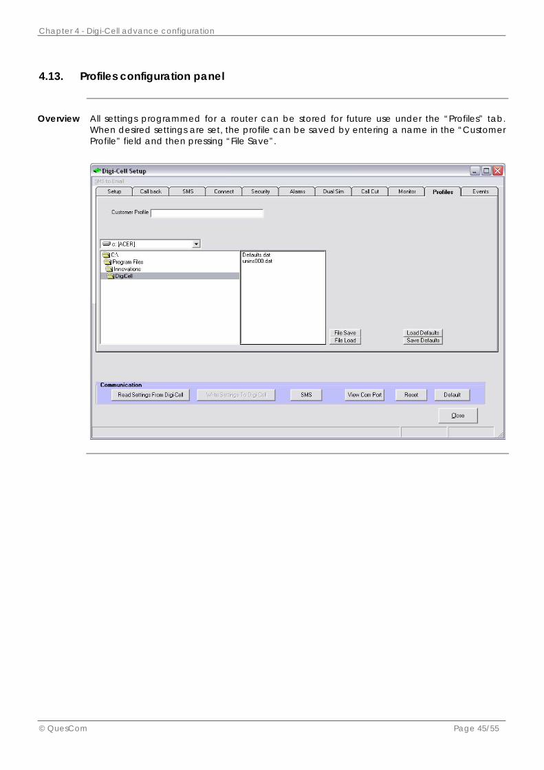
4.13. Profiles configuration panel
Overview
All settings programmed for a router can be stored for future use under the “Profiles” tab. When desired settings are set, the profile can be saved by entering a name in the “Customer Profile” field and then pressing “File Save”.

Chapter 4 - Digi-Cell advance configuration
© QuesCom Page 46/55
4.14. Events configuration panel
Overview
The “Event logging” feature counts each time a series of events occur like “Call not answered” or “Not enough digits dialed”. These counters can be read from the router and reset individually or globally.
These event reports are very useful for checking the status of a router and are also available via SMS. Please note that Firmware revision V9.06 or newer is required for this feature.

Chapter 4 - Digi-Cell advance configuration
© QuesCom Page 47/55
4.15. Firmware upgrade
Procedure
To upgrade the Digi-Cell with newer firmware:
• in order to gain newly added features or
• if you were instructed to do so by a representative of QuesCom
Follow the procedure described below:
Steps Action
1 Open the Digi-Cell maintenance program and select Setup > Boot Loader.
2
On the Boot Loader window opened, set: Parameter Value Com Port Select the correct port number according to your
system Baud Rate The baud rate for the boot loader is always set at 19200
irrespective of the router’s serial number Browse Select the correct firmware file (.hex)to load and click
Open
These are only applicable to the boot loader section and do not affect any previous communication settings done in the maintenance program.
3 Once the correct file has been selected, remove power from the Digi-Cell.
4 Re-apply the power and press the “Start Download” button within the first five seconds of powering the router.
The download should begin and once completed you will receive visual confirmation from the boot loader.
5 Once upgrading has completed, remove and re-apply the power to ensure that the router is rebooted again. This is to ensure that new settings that might be added in new firmware are applied correctly.

Chapter 4 - Digi-Cell advance configuration
© QuesCom Page 48/55
Firmware version
The list below describes firmware versions to be loaded on the different models of Digi-Cell. Please contact QuesCom to confirm the latest revision (eg V8.56, V6.56, V9.05 or V3.31) before loading.
Serial number Firmware Digi-Cell Model
1005-XXXXXXXXXX Version 3 Digi-Cell V1
1007-XXXXXXXXXX Version 3 Digi-Cell V1
1009-XXXXXXXXXX Version 3 Digi-Cell V1
1107-XXXXXXXXXX Version 6 Digi-Cell V1
1118-XXXXXXXXXX Version 8 Digi-Cell V1
1201-XXXXXXXXXX Version 8 Digi-Cell V1
1401-XXXXXXXXXX Version 8 Digi-Cell V1
1402-XXXXXXXXXX Version 9 Digi-Cell V2

Chapter 5 - Digi-Cell basic configuration
© QuesCom Page 49/55
5 . D i g i - C e l l b a s i c c o n f i g u r a t i o n
5.1. SMS Programming
Overview
The following functions can be programmed via SMS sent to the SIM card embedded into the Digi-Cell
Options
Settings SMS format Set SLIC volume SLICVCM,xx,yy (Where xx is the percentage of the volume
for incoming calls, and yy for outgoing call) Add Call back number ADDCBN,Number (ex: ADDCBN,0821234567) Delete Call back number DELCBN,Number (ex:DELCBN,0821234567) Add barred number ADDBAR, Number (ex: ADDBAR,0821234567) Delete barred number DELBAR, Number (ex: DELBAR,0821234567) Add allowed number ADDALL, Number (ex: ADDALL,0821234567) Delete allowed number DELALL, Number (ex: DELALL,0821234567) Get version number VERSION Sending AT commands SMS format: AT+xxxxxxxxxxxxxxxx
Where xxxx is any standard AT command
Note
Please note that the numbers used above are only as an example and should be replaced by the numbers that will be used by the customer.

Chapter 5 - Digi-Cell basic configuration
© QuesCom Page 50/55
5.2. DTMF Programming
Overview
The following functions can be programmed via DTMF tones from a handset plugged into the Digi-Cell unit.
Line reversal
Settings Actions Line reversal begins (double) To set the length of the line reversal pulse at the
beginning of a call in 100ms increments: Dial 888#1 wait for beep and then Dial 0010 for a one second line reversal.
Line reversal at end (double) To set the length of the line reversal pulse at the end of a call in 100ms increments:
Dial 888#2 wait for beep and then Dial 0010 for a one second line reversal.
Single line reversal To set for a single line reversal (One direction at beginning of call and back again at end of call):
Dial 888#1 wait for beep and then Dial 0999. Put down the handset and then Dial 888#2 wait for beep and then Dial 0999
Line reversal check Dial 888#3 wait for beep and then Dial 0010 for the unit to check the call progress of a
call every 10 seconds.
Dial String Setup
To configure the number of digits the unit needs to start dialing and the time it will wait between digits, if number of digits has not been reached, follow the procedure described below:
Settings Actions Number of digits and dial-delay
Dial 888#7 wait for beep Dial xxyy (xx for the delay in seconds and yy for the
number of Digits)
Volume setting
To configure the incoming and outgoing volume, as a percentage, follow the procedure described below:
Settings Actions Volume Dial 888#4 wait for beep and then
Dial xxyy (xx for incoming and yy for outgoing volume)

Chapter 5 - Digi-Cell basic configuration
© QuesCom Page 51/55
Call back and comfort tones
To configure call back tones, follow the procedure described below:
Settings Actions Call back and comfort tones Dial 888#6 wait for beep and then
Dial xxyy Where xx represents: 00 for simulated ring 01 for Beep on dial 02 for busy tone 03 for no tone.
Where yy represents: 20 for number enable 10 for enable all 00 for disable.
The CLI must be activated on the SIM-card in order for dial back to work.
Reboot timer
To set the time that the unit will wait while idles before rebooting, follow the procedure described below:
Settings Actions Reboot Timer Dial 888#5 wait for beep and then
Dial 0300 to set the time to 300 minutes.
Software version
To get the current software version of the Digi-Cell, follow the procedure described below:
Settings Actions Software Version Dial 888#9 wait for number of tone’s in one
frequency and then number of tones in another frequency.
The first frequency indicates the major version number and second frequency indicates the revision number. E.g. Version 1.6 is one beep in first tone and six beeps in second tone.
Signal strength
To get the current signal strength of the Digi-Cell, follow the procedure described below:
Settings Actions Signal Strength Dial 789# the Digi-Cell will then give a number of
beeps out of six to indicate the signal strength out of six. Note that the unit will give the signal strength continuously with intervals in between until you disconnect the line.
DTMF test
To test if the unit receives all the tones sent to it, follow the procedure described below:
Settings Actions DTMF test Dial 1472580369 and the unit will then respond with
five beeps to acknowledge that it has received all the tones.

Chapter 5 - Digi-Cell basic configuration
© QuesCom Page 52/55
Quick volume setting
To reset the volume setting, follow the procedure described below:
Settings Actions Reset volume Pick up the line and put it down five times in succession
to reset the volume setting value to 6565.
Reboot Digi-Cell
To Reboot the Digi-cell, follow the procedure described below:
Settings Actions Reboot Dial 456#

Chapter 6 - LCD Interface & LED
© QuesCom Page 53/55
6 . L C D I n t e r f a c e & L E D
Call information
The LCD provides real-time information about call status and in-call signal strength. The figure below demonstrates how the unit will display information while in standby as well as when calls are being made or when they are in progress.
Menu configuration
The LCD interface can also be used to program the unit without the need for a laptop or computer connection.
Note that the loading of call back numbers can not be accomplished using this method of programming.
To program the unit using the buttons and LCD display please review the menu map in the figure below. The button assignments are as follow:
• Top button will select the menu items indicated below, numbered from 1-7. • Bottom button will scroll down through the current menu. • To edit the displayed option, hold down the bottom button. (unit displays
“EdITINg . . .”) • Now the top button will scroll up and the bottom button will scroll down. • To accept the setting, hold the bottom button again to save the setting.
• To access the Shortcut menu, you must hold the bottom button when the unit is in
standby. • Use the buttons now to scroll up or down and hold down bottom button to select
the displayed option.

Chapter 6 - LCD Interface & LED
© QuesCom Page 54/55
Menu configuration
The figure below describes the menu map:
LED description
The Digi-Cell V2 Gateway is equipped with four LED on its front panel.
It is important to understand the different LED indications so as to identify the different operating states of the Digi-Cell. You could therefore spot quickly any faulty conditions that the Digi-Cell may encounter.
Color and Name Meaning
Orange - USB Unit connected via USB cable to PC
Green – GSM Flashing – GSM network found
Green - ACT Flashing – On call
Red – ERR Flashing – On call On all the time - indicates a problem on the connection from the PBX side or the Unit is faulty.

Chapter 7 - Technical Specification
© QuesCom Page 55/55
7 . T e c h n i c a l S p e c i f i c a t i o n
Technical
The table below provides the technical specification of the Digi-Cell:
Description Specification
Size 126mm x 88mm x 32mm Weight 200g
Cover material Aluminium Extrusion
Temperature -20°C to +55°C
SIM Card Small
RF Power Max 2W
Sensitivity - 113 dbm
Line Voltage Fully Programmable
Line Impedance Fully Programmable
Loop Current Fully Programmable(Automatic shut down if any of the above are out of limits)
Modem Siemens MC55i
Status Indicator 4 x LEDs and 10 Digit LCD screen PC Interface USB (SMS/Fax and Data) Power Supply External (100V - 240V AC) Antenna External SMA Connection / Dual Band
CE and UL Approved