Getting Started With an Unmanaged Switch HUE-500.
13
Getting Started With an Unmanaged Switch HUE-500
-
Upload
grant-marsh -
Category
Documents
-
view
218 -
download
0
Transcript of Getting Started With an Unmanaged Switch HUE-500.

Getting Started
With an Unmanaged Switch
HUE-500

The Components
The switch, DIN and wall mount brackets and manual ( CD )

The Components
The switch, showing the TX ports and their caps

The Components
The label w/ serial number and agency approvals
The Components
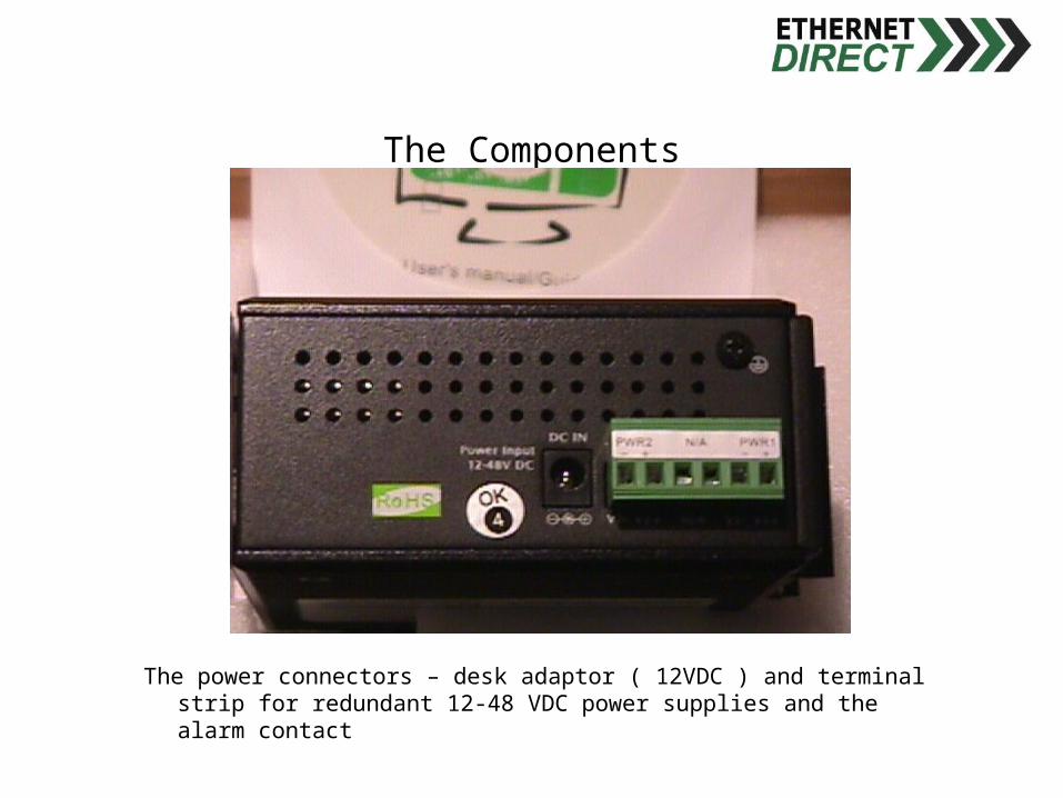
The power connectors – desk adaptor ( 12VDC ) and terminal strip for redundant 12-48 VDC power supplies and the alarm contact

The Components
The power terminal strip for redundant 12-48 VDC power supplies and the alarm contact removed from the switch

The Components
- + ( to PLC input) - +
24 VDC alarm wiring 24 VDC

The Components
Remove protective port caps from the TX ports for any of the ports that you will use.

The Components
Insert the copper TX cable connectors, RJ45s, into the port socket – it will ‘click’ when properly seated. Replace the protective caps into any unused ports.


LED Status MeaningPower Green Switch has power from
Power 1 and/or Power 2
Power off No power to switch
Power 1 Green Power 1 terminals have power
Power 1 off Power 1 terminals have no power/not connected
Power 2 Green Power 1 terminals have power
Power 2 off Power 1 terminals have no power/not connected
LNK/ACT Green Port has linked
LNK/ACT Flashing Transmitting, Receiving packets
LNK/ACT off No device connected

LED Status MeaningFDX/COL Yellow Port is operating in Full Duplex mode
FDX/COL Flashing Packet collisions on port
FDX/COL Off Port is operating in half duplex mode or no connection
Port 1 to 4 LEDs Yellow Port is operating in Full Duplex mode
Port 1 to 4 LEDs Flashing Power 1 terminals have power
Port 1 to 4 LEDs Off Port is operating in half duplex mode or no connection
Port 1 to 4 LEDs Green A network device is connected to the port
Port 1 to 4 LEDs Flashing Transmitting, Receiving packets
Port 1 to 4 LEDs off No device connected
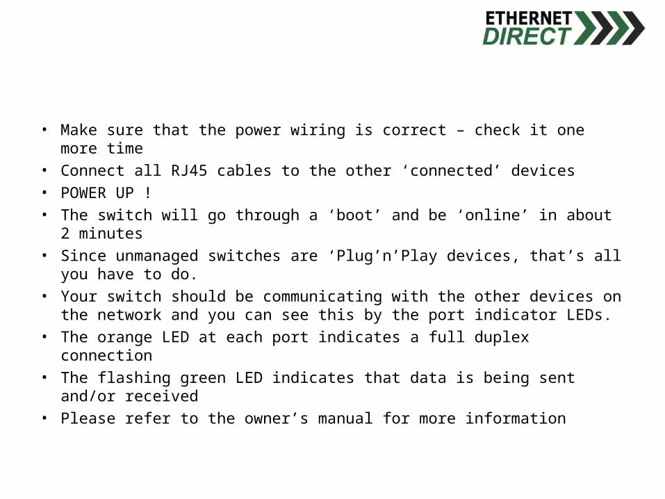
• Make sure that the power wiring is correct – check it one more time• Connect all RJ45 cables to the other ‘connected’ devices• POWER UP !• The switch will go through a ‘boot’ and be ‘online’ in about 2 minutes• Since unmanaged switches are ‘Plug’n’Play devices, that’s all you
have to do.• Your switch should be communicating with the other devices on the
network and you can see this by the port indicator LEDs.• The orange LED at each port indicates a full duplex connection• The flashing green LED indicates that data is being sent and/or
received• Please refer to the owner’s manual for more information