
Getting Started: Help for RC Plane Newbies - SCCMASsccmas.org/pdf/Training/Newbie Help 19 Oct...
20
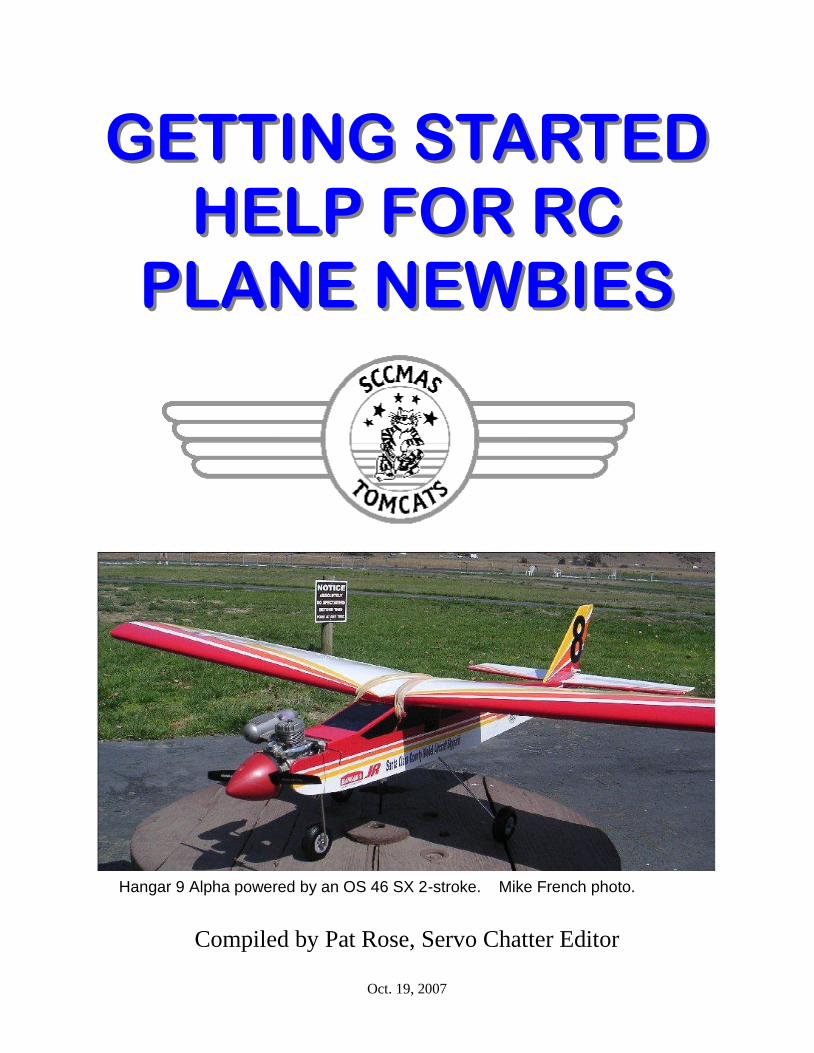
GETTING STARTED GETTING STARTED HELP FOR RC HELP FOR RC PLANE NEWBIES PLANE NEWBIES Compiled by Pat Rose, Servo Chatter Editor Oct. 19, 2007 Hangar 9 Alpha powered by an OS 46 SX 2-stroke. Mike French photo.
Transcript of Getting Started: Help for RC Plane Newbies - SCCMASsccmas.org/pdf/Training/Newbie Help 19 Oct...
GETTING STARTED GETTING STARTED
HELP FOR RC HELP FOR RC
PLANE NEWBIESPLANE NEWBIES
Compiled by Pat Rose, Servo Chatter Editor
Oct. 19, 2007
Hangar 9 Alpha powered by an OS 46 SX 2-stroke. Mike French photo.

2
Hello RC Plane Newbie, Greetings to all of you that are new to the radio controlled airplane hobby. While meeting new or prospective new members at the SCCMAS field, I often found myself referring to articles found in past issues of our club newsletter Servo Chatter. So to make things easier for every-one, I started this project with a list of contents, thinking I would simply pass out the list, refer-encing past issues of the newsletter. After making my list, I got ambitious and decided to put this document together with the contents reflecting subjects that would be helpful to the RC newbie. I borrowed heavily from the works of Mike French, Tim Jones and Michael Luvara; not all the contents having been previously published in Servo Chatter. Hopefully the contents of this publication will help you overcome some of the hurdles to be-coming an accomplished RC pilot. Enjoy, Pat Rose Editor, Servo Chatter
Table of Contents
What I learned in my SCCMAS Primary Flight Training……………………..………...3
Lessons for a new RC Flier…………………………………………………………….…5
RC Plane Control Inputs…………………………………………………...……………...6
Preflight Model Aircraft Inspection Criteria & Guide………………...………………….8
Recommended Equipment……………………………………………………………....10
More Lessons for Veteran Beginners…..…………………………..…………………..11
Don‘t aim it at the Plane………………………………………………...………………..12
2.4 GHz Radio Introduction…………………………………………...…………………15
Trimming a Sport Plane………………………………………………...…………...…...17
Reliable Engine Operation and Flight Trimming Notes…………………...…………..20
Getting Started Help for RC Plane Newbies is published by the SCCMAS “Tomcats” radio control club located in
Morgan Hill, CA. Views expressed are those of the writers. They do not necessarily represent the views of the
club, its members, or officers. Mention of any product, material, or service shall not, nor is it intended to, imply
approval, disapproval, or fitness for any particular use. The SCCMAS is a non-profit organization. Permission is
granted to reproduce anything printed in here as long as the source and author are credited.

3
What I learned in my SCCMAS Primary Flight
Training By Anand Phatak
To fly a model airplane was something I had al-ways wished since the time I saw a model air show back in my school days. It took me 20 years, however, to actually get into it. A tiny electric plane purchased by a friend inspired me to finally pursue this childhood dream. I started researching the clubs in the area and discovered SCCMAS on Google. One of the clubs benefits was free train-ing. It had not occurred to me until then that this hobby needs a good amount of training. I picked up the phone and called the club. I was expecting a voice mail but actually got to speak with the president! He gave me good advice to visit the club and to see everything in person to get an idea of what to expect. I drove to the club and was very happy to see this wonderful facility. People were friendly and guided me as to how to obtain an air-plane and contact the club's instructors. I called Mike French, the director of flight instruction He willing agreed to become my instructor. Mike had emailed me an aircraft-readiness check list prior to the first training day. I followed the in-structions, prepared my NexStar trainer to the best of my ability, and was quite happy with the result. Having a Mechanical Engineering degree, I thought that this would piece of cake. I met Mike at the field on the first day. I was all too eager to get my plane into the air and do my first aerobatic maneuver. We started by inspecting my aircraft. My plane went through serious scrutiny. He pointed out at least 10 hazards to flight with my plane. That came as a shock! And I thought my plane was fit enough to carry live passengers. But I couldn't disagree with anything he had noted. He explained everything to me in great detail and I agreed (fo) go back and make the repairs. We didn't however discard my machine completely as we flew my plane‘s maiden flight that day. I had thought it would take me 3 to 6 lessons to become a good pilot. After all, it is just child‘s play, isn't it? I had bought a flight simulator. I could take
off and land on it. But I was dead wrong. I had never expected that flying R/C plane was quite so challenging and involved many safety precautions. I didn't know each plane has a "personality" which you need to get accustomed. I didn't know altering small settings to the control surfaces could have such a big impact on the flying characteristics. I didn't know how to deal with wind speed, wind gusts and direction. An untrained R/C pilot can be a big threat to his plane, to himself, to others and their planes on the field. I was about to discover and learn all this throughout my training. On each instruction day, I learned something new. Mike explained each aspect in great detail: The importance of "TRACK" - a model pilot's preflight check acronym - (which helped me detect a big flaw in my plane at a later date which undoubtedly saved it from crashing), battery voltage checks, checks on the linkages, cracks, importance of not spilling fuel on the field, sensitivity of the con-trols, recovering from disorientation... the list went on.
What I Learned continued on page 4.

4
What I Learned continued from page 3.
Sure, at times I was too eager to fly and start seeking fun from this new exciting hobby, rather than practicing the essential details. But soon I started to realize the unforgiving nature of our sport. You cut corners and you lose your plane. Worse, your plane could be a threat to others on the field. All this started becoming clearer with each session. So where was the fun factor in lean-ing to fly models you might ask? After all we pursue hobbies because they are sources of great pleasure. I learned that in this hobby the fun part arrives after you pass the first part of your
learning curve. When you learn to how to take off and land, maintain your plane, know how to save it from disasters (most of the time) and fly it safely, there is a great deal of fun here! When you do your first aerobatic maneuver, land your plane with style, save it from a dead-stick landing, you sud-denly discover the treasure. It's all fun after that. But what good training could give you is a life-long ability of sustaining and enjoying this great sport. Learning it right the first time is the best way. I am grateful to SCCMAS and Mike French who has
given me that opportunity. - AP o

5
Lessons For a New RC Flier By Tim Jones This hobby, or sport if you will, has just been a kick for me. I‘m fairly new to flying Radio Con-trolled model aircraft. I‘d built and destroyed sev-eral control line planes as a youngster. The most recent when I was 22, a youngster compared to my present age. Getting into this hobby at the RC flying level was a bit of a jump. When I was a youngster, Radio Con-trol was the ultimate plateau. Now I‘m in it. I started hanging around the SCCMAS field around the early part of 2002. Done playing with hot rod cars, my kids nearly grown, my house virtually rebuilt, I was looking for something to entertain me. I tried golf. It‘s entertaining at the time I‘m playing the game, but, that‘s about all. Hunting took too much planning, preparation and driving. I decided the flying field was it. I was buying a plane, an AMA card and a club membership. From that day on, I‘ve had a great time. My choice was a Hobbico Avistar. I ordered everything at the same time, on the same day. Ready to Fly air-plane, AMA membership (by Fax), and a club membership. I scared up some of my old glow fuel supplies and went to Sheldon‘s to get a few more. When my plane arrived, I was as excited as the day I got my learner‘s permit to drive. This was going to be great. I had my AMA faxed confirma-tion, my new untried club card and a new airplane. The lessons were about to begin.
The first lesson I learned, those who fly model air-planes will teach someone else to fly model air-planes. All those who fly have their own way of teaching others. All are helpful.
The second lesson, gravity is constantly working against you. I personally feel that gravity is unfairly biased against the new flier. (Reggie doesn‘t get his fair share of gravity.)
Third lesson, propellers are very hard on human flesh. A starting stick of any kind is better than your finger. And of course, the electric starter is the best way to go.
Lessons two and three lead to a whole new book of lessons. These lessons include propeller re-placement, application of band aids and some-times an enhancement to one‘s vocabulary of word you don‘t say around mom. Also included are impromptu lessons in small wood parts fabri-cation and reinforcement. Lessons in gluing these fabricated and reinforced parts together. Lessons in removing one‘s glued fingers from these glued parts assemblies. Lessons in applying covering material. These may be large or small lessons, depending on your share of gravity for the previ-ous day. I‘ve seen some lessons demonstrating techniques in tree climbing of all things! The possi-bilities for lessons for the beginner are endless.
One of my personal favorites is the lesson of shar-ing your learning experiences with a group of new friends and enjoying a good laugh with these friends sometimes at your own expense. Damn, this is fun. And we won‘t even go into the first in-troduction to racing. That can make you laugh hard enough to hurt yourself.
I‘d like to see a few lessons presented at a group level, such as a club meeting or a notified day at the field. I‘d like to see some beginner lessons presented. Examples? How about a demonstra-tion for beginners for the uses of various glues and accessories. Like glues or bonders if you will, debonder, accelerator or kicker. Epoxies and addi-tives for fillers and strengtheners. Cleanup tips for both. How about a little talk for propeller selection. Balancing of propellers. Differences or effects of pitch, diameter and blade profile selection. Glow plugs? What‘s the difference? Battery care? Maybe a covering demonstration. How about add-ing trim and detailing to your covering. Balancing of planes. How about a demonstration at the field for various maneuvers to learn?
These are just a few thoughts I have. I‘ve gotten a few answers. I‘ve shared a few discoveries. I‗m still working on that gravity thing. I sense more laughter coming. From one beginner and maybe several others, thanks for the lessons Tomcats,
and keep sharing. o

6
Figure 1. Controls at engine idle (left stick) and neutral (right stick).
RC Plane Control Inputs by Pat Rose
Figure 2. Left stick moved forward by RC pilot. This throttle input powers the plane forward. Guest does not touch left stick unless directed by RC pilot.
Figure 3. Right control stick pulled back—plane pitches up.
Figure 4. Right control stick pushed forward—plane pitches down.

7
Figure 5. Right control stick moved left. Plane banks left.
Figure 6. Right control stick moved right. Plane banks right.
Note: Figures 2 thru 6 show control movement exaggerated. Only small movements (1/16 to 1/8 inch) are usually needed. To gain altitude, see Figure 3. To lose altitude, see Figure 4. To turn left, bank left (Figure 5), neutralize controls (Figure 2), pitch up (Figure 3), neutralize controls (Figure 2), bank right to level wings (Figure 6), neutralize controls (Figure 2). To turn right, bank right (Figure 6), neutralize controls (Figure 2), pitch up (Figure 3), neutralize controls (Figure 2), bank left to level wings (Figure 5), neutralize controls (Figure 2). Have fun!!!!!!

8
Preflight Model Aircraft Inspection Criteria & Guide
By Mike French
The following document is an unofficial guideline to serve as a basis for inspecting aircraft for safety and
other operational needs prior to flight. This list is not offered as being all-inclusive but attempts to cover the more
common problems found on aircraft that come to fly at the SCCMAS field for the first time. Preliminarily inspect
your aircraft while checking off the boxes. Bring this completed checklist when you come for your aircraft inspec-
tion and orientation session.
Internal Antenna The aircraft antenna should be placed internally to the aircraft and not at-
tached to the tip of the vertical stabilizer. The reason is to allow free access
to the empennage by a tie down rope which will be required for operation in
the startup area. Antenna should exit the A/C at bottom rear.
Nose Wheel Drag The nose wheel must NOT rotate freely. Drag is needed on the nose wheel
to inhibit the aircraft from taxiing at optimum engine idle RPM. Thin fuel
tubing on either side of the nose wheel works well.
No Single Point Failures Post control horn attachment provided in many current trainers secure the
push rods with only one set screw. Either replace the posts with a clevis pin/
adapter combination or secure the set screw/push rod with a light coating of
Loctite.
Gas Tank Security Some trainers do not properly secure the gas tank in the aircraft. The gas
tank must be rigidly attached to the fuselage. Glue plywood strips to the fu-
selage with foam separating the tank from the strip to prevent abrasion.
Main Wheel Collars Some trainers secure the main wheels to the landing gear with a brass collar
secured only by a setscrew. At a minimum Loctite the collar and setscrew.
Recommend that the collar be removed and replaced with a length of fuel
tubing on either side of the main wheels.
Battery Charger Port We recommend that a battery charging port be installed on the opposite side
from the muffler such that the battery voltage can be monitored prior to each
fight instruction session without the removal of the wings. A three flight
training session would proceed if battery voltage at the start of the session
exceeds 5.0 Volts. No individual flight should start with less than 4.8 Volts.
Bands Around Clevis Pins All Clevis pins should have a thin band of fuel line surrounding the part to
prevent loss of linkage with the control horn.
Secure Control Surfaces All control surfaces should move without slack to their control servo. We see
many instances of control surfaces not well attached to the aircraft.
Minimum Length Fuel Line Keep fuel line length to an absolute minimum. No arching curves of fuel line
between the tank and carburetor.
Secure Engine Mounts. Engines should be directly fastened to the aircraft’s engine mounts. Engine
clamps are to be discouraged. Drill holes in the engine mount and use an
appropriate tap to create threads. 6-32 bolts 1 ½ inches long work well for
engines of .51 cu in or smaller.
Preflight Model Aircraft Inspection continued on page 9.

9
10 or 11 / 4 or 5 Props Trainers are not flown for speed. Keep the propeller’s pitch low as what is
needed is torque and not speed. Bigger engines require longer props.
No Floating Electronics Some trainers secure the receiver and battery with Velcro tape. This is dis-
couraged as Velcro has a tendency to unhook in flight. Batteries particularly
need to be properly secured to the aircraft. Use a cable tie if necessary but
directly secure both the receiver and battery to the aircraft.
Labeling The pilot’s name, address, phone numbers and AMA number need to be
placed permanently both on the aircraft and the transmitter prior to brining
the aircraft to the field.
Channel Numbers The channel number for the transmitter should be easily seen on the antenna.
Be sure that your channel numbers are secured to the transmitter’s antenna.
Tie Down Rope Be sure that you have a 5’ tie down rope with a clip to attach it to the fence
such that the aircraft can be started without fear of it moving.
Label Support Equipment Engine starters, glow plug starting batteries and fuel kits should have your
name on each item. We collect too many nameless support items.
Needle Valve Extension Wire Fabricate from a 1/16” wire a 1½ “ extension to the needle valve of your
engine. Most engines have a hole drilled in the end of the needle valve with
a right angle Allen head set screw to secure the wire. Add a 90º ¼” bend and
then place a little epoxy [JB Weld] on the end of the wire to prevent a hazard
from stabbing yourself while attempting to adjust the mixture setting on a
vibrating engine. The extension helps keep fingers from being prop sawed.
Closed Loop Fueling When you fill the gas tank of your aircraft, there must be a return line from
the aircraft overflow back to the gas container. When the aircraft tank is
filled, we do NOT want to find gas has been splattered on the asphalt. The
caps to gas tank fueling systems have a return port. Be sure that yours is con-
nected and operational.
Exhaust Port To Vent Over Wing Rotate the exhaust port vent such that the exhaust gases and oil are throw
AWAY from the fuselage and OVER the top of the wing as much as possi-
ble. The object here is to minimize the oil-laden gases from seeping under
the wing into the chamber containing the electronics and servos.
Adjust Throttle Linkage To Cut Off Adjust the throttle servo and engine linkages to effect complete cut off with
the throttle lever at minimum and throttle trim at it’s bottom most travel.
Cutoff occurs when ALL the arc of the rotating throttle assembly is hidden.
Buddy Box Cable Be sure that you have a Buddy Box Cable for/with your transmitter.
SCCMAS has a few cables that might serve in a pinch. But like your
toothbrush, it is best to have your own that matches your particular transmit-
ter. SCCMAS has plenty of Buddy Box Transmitters that can be used by the
student. The student transmitter has the standard round ended connector for
the cable.
Preflight Model Aircraft Inspection continued on page 10.

10
Flight Simulator There are many good flight simulators for your PC. The best one that I have
used is produced by Great Planes, Inc. Real Flight, Generation 2 (G2) is ex-
cellent. Look at http://www.realflight.com/g2_main.html. I have had good
success with it. It is a little bit pricey but it is worth it. A flight simulator will
reduce your training time by more than half and have uses after you pass
your solo pilot’s test. I still use mine from time to time.
Equal Nose Gear Deflection The nose gear control arm must not be parallel with the firewall. It must be
connected to the main gear at roughly a 30º angle so that control rod can
deflect the nose wheel equal angles about the A/C center line.
Recommended Equipment Condensed from Michael Luvara‘s Manual
Aircraft & Kits: With today’s ever changing Radio Control market, there are many kits and almost ready to fly (ARF) aircraft available. We recommend any .40 to .60 size high wing trainer which has a flat bottom or semi-symmetrical wing.
Engines: In purchasing an engine, there are two types - two stroke and four stroke. We recommend a two stroke. They are available with ball bearing or bushing supported crankshafts. The ball bearing versions put out more power, and are somewhat more expensive than the bushing versions, but ei-ther work fine, provided they are the right size for your airplane. Engines must be equipped with muf-flers. Those using gas engines at any time should carry a fire extinguisher with them to the field.
Propellers: APC is the most common propeller used for train-ing. This is because the props are made of glass-filled nylon and can take some abuse from hard landings. Wood props are a lot safer when being used, but will break on a bad landing. Propeller sizes will be outlined with your motor’s manual. Use a spinner or propeller safety nut on your mo-tor.
Fuel: Fuel comes in many brands and types. Please see what your particular motor manufacturer recom-mends. In general, 5% to 15% (percentage is amount of nitromethane in fuel) is commonly used in regular sport motors. Fuel is composed of methanol, nitromethane, and a mixture of synthetic or castor oil for a lubricant. Please avoid spillage of excess fuel onto any area of the field and use an overflow bottle to collect excess fuel and protect the asphalt. In the course of a day’s flying, you can save a tank or more of fuel.
Radios: Selecting a radio can be a confusing part of enter-ing the Radio Control hobby. There are many brands available and everyone likes a different one
for one reason or another. Radios must have trainer cord capability.
Field Equipment: Glo plug ni-starter (1.5 volt battery used to ignite glo plug) Chicken stick or electric starter Propeller/glo plug wrench Extra propellers Misc tools (screwdrivers, wrenches, pliers) Glue (for small field repairs) Extra glow plugs Fuel pump (manual or electric) Overflow Fuel container Cleaner for hands and airplane Field box to hold all of the above.

11
More Lessons for Vet-eran Beginners By Tim Jones
I‘ve been learning lessons, as I‘ve written earlier, from the moment I gave serious consideration to giving this hobby a shot. So, I‘ve been having fun with this for a couple of years now. As I‘m still a beginner in many aspects of this hobby and I‘ve got a couple of years now, I consider myself a bit of a veteran and a beginner. So, ―Veteran Begin-ner‖.
The basic beginner lessons are still there. I‘ve improved on them. I haven‘t dinged my finger with a prop in a long time now. But I do continue to glue my fingers to balsa wood. I continue to see that veterans enjoy and helping a beginner. But if a ―Veteran‖ of any caliber, messes up a take off, steps on his antenna, flies off with the glow driver still hanging on his plane or snags a bowling ball in the safety net, there is no mercy in nominating him for Dumb Thumb. I‘ve gotten sev-eral dumb thumbs already. I feel ―Accepted‖. I consider Dumb Thumb a badge of honor. Every Dumb Thumb has a good time attached to it. I‘ve improved my talent for applying covering. But my choices for color section have a ways to go. I continue to enjoy sharing laughs at the field. The more time I spend at the field, the more I get to laugh, often at myself. The trees at the south end are still taller and closer than they appear. The weeds are often taller than they appear. Some-times, the runway is shorter than it appears. These are some of the lessons learned in the very beginning. They continue to be very valu-able lessons.
Now for the more lessons part. I‘ve learned that there is some truth in the saying that you can‘t have too may planes. Though this is a debatable statement and hard to defend, it appears to be true. Somehow, I always have some twisted justi-fication in buying another plane. I‘ve learned to work different angles in explaining this justifica-tion to my wife, although, it is getting tougher to do. I‘ve learned that the dining table is not a place to store parts, assemblies or materials, or a convenient place to work on propeller balancing or fitting engine mounts. (That one was for
Wendy.)
I‘ve learned that it is not uncommon to have sev-eral spare engines, airplane ARF kits, servos and receivers, just in case the urge hits you to put something together. I‘ve learned that if you have several of the same spare prop, they will be with you at the field in your box. But if you have only one spare for the plane you took with you on any given day to the field, it will be at home on the bench. If, while you‘re driving to the field, you wonder if you remembered your transmitter, you have a fifty – fifty chance that you have it with you. If, however, you think about it and are sure you remembered it, you will have to go back home to get it or enjoy the day ―Hangar Flying‖.
I‘ve learned that there is always a deal some-where at the swap meet. These deals will often present the opportunity to work that talent for the twisted justification for bringing another project home. I‘ve learned that E-bay and Tower Hob-bies are not good places to browse around when you have idle time. You‘re much better off using that time to assemble one of the kits you already have, or repairing one of the planes you‘ve set aside to repair another day. I‘ve learned that if everything you have is repaired or built, your computer internet connection will be down, so you can‘t browse for another project. So, you have to buy something while you have the oppor-tunity, just in case.
Overall, all of the lessons are fun. Helping a new flier at the field get signed off and watching him smile when he successfully completes his first one hundred percent solo flight is one of the most rewarding experiences in the hobby. I‘ve found that there is no word that can truly describe the feeling of a greased tail dragger landing on the mains and flying the tail down the runway for a soft tail set down and taxiing back to complete a flight.
I‘m learning more lessons. I‘m getting into racing. I‘ve got twelve points on the series so far. But, that‘s another list of lessons.
Stay tuned……………………..o

12
The following article copied from Peak Charge, the
monthly newsletter of the Silent Electric Flyers of San
Diego, March 2006 issue.
Ever had the situation where your plane is flying just fine and you are coming in low for a landing when all of a sudden the plane does something really weird….totally out of your control? You probably thought your plane received a radio inter-ference ―Hit.‖ More than likely, you caused the out-of-control situation by pointing your transmitter‘s antenna at the plane. Just last week, at our flying field I saw a fellow totally destroy a beautiful pattern plane when it violently augered into the ground. The plane had been flying low, toward the pilot, and the pilot was pointing his transmitter antenna at his plane. Since the plane‘s receiver antenna was basically streaming along the plane‘s centerline, both trans-mitter and receiver antennas were, for the mo-ment, pointed at each other resulting in total loss of communications...and of course, any control of the plane.
Did you know that the thirty-to-forty inch (quarter wavelength) antenna on our radio radiates essen-tially ZERO radio energy in the direction pointed? Maximum energy from a quarter wavelength an-tenna occurs at a right angle (90 degrees) from the axis of the antenna. There is an almost straight line relationship between energy transmit-ted (or received) and the angle from the antenna axis. It starts at zero output in the direction of the antenna‘s axis, then it goes up to a maximum at 90 degrees from that axis. So now when you are flying, especially when com-ing in on a low approach for landing, be sure to position your antenna at a right angle (or at least 45 degrees—ed) to the plane. Do this every time and you will likely never again be plagued by a so-called radio ―Hit.‖
Don’t aim it at the plane! By Walt Jellison
Here the transmitter antenna is pointed directly at the departing and arriving plane, with the plane‘s antenna (in the fuselage) in a similar pointing arrangement. This is the worst possible situation.
Figure 1 Figure 2
Following photos by Pat Rose. I‘ve been meaning to put together something like this for some time, and Walt‘s article got me started. Walt gives an excellent explanation of this antenna aiming subject.

13
Photo 3 Photo 4
Photo 5 Photo 6
Photo 7 Photo 8
Photo 6. Antennas oriented for maximum received signal, just like photo 7. Best arrangement.
Photo 7: Antennas oriented for maximum received signal, just like photo 6. Best arrangement.
Photos 3 and 4 illustrate at least one antenna (receive or transmit) at 45 degrees to the other. This situation is better than photos 1 and 2.
Photo 8: Here the transmitter antenna is pointing above the plane, a preferred position relative to pho-tos 1 and 2. Aiming below would be equally good.
Photo 5. A transmit antenna position better than photos 1 and 2.
(Antenna aiming, continued from page 12.)
(Continued on page 14.)

14
There is one more characteristic about antennas that needs explanation. Just as Walt explains that pointing the transmitter antenna at the plane can-cels the transmitted signal towards the plane, there is a characteristic described as polarity that can have a similar effect. Photos 6 and 7 illustrate what is called horizontal polarity for both the trans-mitter and plane antennas. Maximum signal is received by the antenna in the plane when both the transmit and receive antennas are similarly polarized; both horizontal or both vertical. The bottom line is this: When performing a range check, move the transmitter antenna around—
pointing up, down, right and left. From one range check to another, keep the plane oriented at a similar angle to the transmitter for consistency. Also, if you experience a ―Hit‖ while flying your plane, immediately reorient your transmit antenna (I know, things happen real fast). You just may be able to save it. One more thing. If you have a large plane, run the receiver antenna both verti-cally and horizontally as space allows. For in-stance, straight back through the fuselage and up into the vertical fin.
PR o
(Antenna aiming continued from page 13.)

15
2.4 GHz Radio Introduc-tion By Pat Rose (This message leverages heavily from Mike Lu-vara‘s article The 2.4 GHz Phenomenon in the May 2007 issue of Servo Chatter.) What is frequency, and BTW what is a radio? Think of a grandfather clock which has a pendu-lum that swings back and forth at a rate of one swing to the right followed by one swing to the left in one second. This clock‘s pendulum is operat-ing at a frequency of 1 cycle per second, also known as 1 Hertz. So, let‘s assume we have an electronics circuit that operates at 72,000,000 Hertz—we‘ll call this 72 Mega Hertz or 72 MHz. This happens to be a frequency of operation to which we can connect an antenna and transmit electromagnetic energy into space. To receive the transmitted frequency, it helps to have a receive circuit that is tuned to the same frequency as the transmit frequency. A transmitted signal operating at 72 MHz or higher is considered a ―radio fre-quency‖, because it takes a radio with tuned cir-cuits to transmit and receive the signal. Radio frequency emissions have a characteristic wave length that is inversely proportional to fre-quency*. In other words, the higher the frequency, the shorter the wave length. A 72 MHz signal will have a wave length of about 402 centimeters, con-trasted with a 2.4 GHz signal with a wave length of 12.5 cm. (2,400,000,000 Hz = 2.4 GHz). It turns out that antennas for our RC radios work well to transmit their signal when built to 1/4 wave length. So a 72 MHz antenna would be about 100 cm and a 2.4 GHz antenna would measure about 3.1 cm. This explains the differences in antenna lengths used between the conventional 72 MHz radio and the newer 2.4 GHz radios. It turns out that the receive antenna follows the same rules as the transmit antenna, so you will notice that the 72 MHz receiver antennas are much longer than the new 2.4 GHz receiver anten-nas. Notice in the photo of the Futaba radio how short the transmitter antenna is compared to one of our usual 72 MHz radios.
Digressing a bit, assuming you are using a 72 MHz transmitter and you forget to extend the an-tenna—what you have is an antenna set to the wrong length for the frequency. Therefore much less of the signal strength is transmitted and you end up with a plane that is out of control soon after take off. Digressing even further, see the July 2006 issue of Servo Chatter for an explanation of signal strength versus antenna orientation. The same principles apply to the 2.4 GHz radios. Our 72 MHz radios transmit between Channel 11 (72.010 MHz) and Channel 60 (72.990 MHz) - we usually choose the frequency when we purchase the radio. Note that these conventional radios transmit on one and only one frequency. If two transmitters are turned on simultaneously with the same frequency, ―Houston, we have a problem.‖ The receivers installed in both airplanes are con-fused by the two simultaneous identical frequency signals and communication fails. The 2.4 GHz ISM frequency band includes all fre-quencies between 2.4 and 2.5 GHz, a span of 100 MHz. This band is wide open and is utilized by such applications a microwave ovens, telephones, WiFi, and model airplane control. There is literally a ―storm‖ of products using this frequency spec-trum. There are two main frequency utilization schemes in use today in the RC hobby. First, there is the technique which finds two unused fre-quencies, then locks on these two frequencies. One frequency is used for the primary control of the model, and the second frequency is used if interference is encountered on the primary chan-nel.
2.4 GHz Radio Introduction continued on
page 16.

16
2.4 GHz Radio Introduction continued
from page 15.
The second scheme in use is the spread spectrum technique which uses only one frequency - this frequency changes every 2 milliseconds (0.002 Sec) within the 2.4 GHz ISM band. Therefore fre-quency conflicts are short lived and there is es-sentially no signal interruption. (Disclaimer: spread spectrum technology is diverse and con-stantly changing.) Since the operating frequency is constantly chang-ing, it makes no sense to use frequency pin con-trol for these radios. However, the AMA recom-mends that a 2.4 GHz pin is used when flying with these radios. Even though the AMA recommends 2.4 GHz frequency pins, RC pilots at the Tomcat
field are seldom seen using them; it would be a tough sell to enforce this rule. One more final note: You will notice the 2.4 GHz receivers have at least two antennas. As ex-plained earlier in the July 2006 issue of Servo Chatter, there is a difference in received signal depending on how the transmit and receive anten-nas are oriented. This effect gets worse as fre-quency increases. To work around this issue, the 2.4 GHz receivers use at least two different re-ceive antennas with the goal that one of them will have a better orientation relative to the transmit
antenna. O
2.4 GHz Receive Antenna Orienta-
tion
Now that I have your attention relative to frequency
versus antenna length, I might touch on one more item.
Just as the Earth can shade the moon from the Sun’s
light rays and cause an eclipse of the moon, a similarity
can be imagined with the 2.4 GHz radios. With the
orientation of the RC plane pointed directly at the
transmitter, toward the pilot, the engine (a big hunk of
metal) or other electrically conductive parts (as in re-
tracts or carbon fiber) can “shade” the receiver antenna
(s) from the transmitter signal and possibly cause tem-
porary loss of control. No doubt the radio designers
have spent countless hours working around the issue of
received signal strength. Anyway, as soon as the plane
changes direction because of this loss of control, the
receiver antenna(s) is once again exposed to the RF
signal and control is regained.
With the small size of the 2.4 GHz receive antenna, it is
especially important to keep them away from other
conductive material such as servo wiring, the battery,
etc., or at least orient the antenna at 90 degrees to the
nearby wiring. O

17
I use the following procedures to trim my planes. By ―trim‖ I mean making adjustments to the plane and transmitter that make the plane easier for me to fly (goes where I point it) and has fewer bad habits. Hopefully, you may find some value in my experience, so here goes. The sequence of mak-ing the trim adjustments does matter. The follow-ing is typical of the trims I have used on my 46 size U-Can-Dos (I‘m building my fourth one), 90 size 3D Mayhem, 90 size Cub, and most recently my 60 size Edge. It is always suggested that fly-ing adjustments be made on a calm day, but since mother nature seldom cooperates, you‘ll just have to do your best. The following assumes that a first flight has been made and control response and neutrals have been adjusted. CG The first ―trim‖ adjustment on a plane is the CG. Try to achieve CG balance by moving the battery, receiver, servos, and etc. without adding any weight to the plane. These adjustments can re-quire a lot of creativity to come out right. I would recommend the plane builder (ARF or kit) to use the CG recommended on the plans. In the case of my recently completed Edge, I put the CG right in the middle of the recommended range. Move the CG past the rear limit of the recommended range and watch out, your plane may have some nasty snap habits. I‘ve done this once by mistake and wound up performing a snap on landing. Ouch! The plane landed upside down. On my U-Can-Do, the CG is near the rear limit as explained in the manual and flies well, snapping and rolling on demand, but still landing easily. Lateral Balance This is the adjustment I believe that most new builders forget to make. A plane that isn‘t bal-anced will dip a wing (among other things) on landing. The wingtip of the plane that is the heav-ier side is continually getting scuffed and torn up on landing. I make both a static balance adjust-ment described here and later check balance with the plane in the air. To check the lateral balance may require two people. One person supports the rear of the plane in the rudder hinge area and the other person balances the front of the plane on the prop nut. Lift the plane and watch the heavy wing dip. Add stick-on lead weight in small increments to the light wing tip until there is no longer a domi-
nant heavy side. My Edge required about one half ounce on the left wing tip, the tip opposite the weight of the engine.
Dynamic Balance This step checks the planes‘ balance during flight. Take the plane up high, chop the throttle and put the plane in a dive. Pull the plane level at a con-venient height and watch for a wing to dip. Per-form this check several times before adding or deleting the stick on lead weights. With my Edge, this step was not needed as the plane was bal-anced. Engine Up/Down Thrust A plane that is not properly adjusted for up/down engine thrust will have some exciting habits on landing when the throttle is adjusted back. To check for engine up/down thrust, fly the plane in the up wind direction from left to right or right to left with full throttle. Just before the plane is di-rectly in front of you, chop the throttle to idle. The plane should continue to fly without pitch change. My last U-Can-Do had a nasty engine down thrust built into it so that on landing, with engine adjusted to idle, the plane would balloon up and I would have to fight the plane and apply down elevator. It was obvious that engine down thrust was hold-ing down pitch; when the throttle was cut, the plane‘s trim flew the plane up. To solve the prob-lem, I loosened the screws that hold the engine Trimming a Sport Plane (continued on page 18)
Trimming a Sport Plane (assumes you are using a computer radio) By Pat Rose
Battery placed here to achieve proper CG. Balsa box con-structed to hold bat-tery.

18
Trimming a Sport Plane continued from page 17.
mount to the firewall enough to slide in small pieces of 3 x 5 card stock between firewall and lower engine mounts. To achieve multiple layers, accordion fold the paper. Some people use metal washers. The U-Can-Do required several attempts at this adjustment because the plane was built with way too much down thrust. Don‘t forget to use a small drop of blue thread locker on the en-gine mount screws to keep things from coming apart.
Engine Right/Left Thrust
This adjustment assumes an engine thrust to total weight ratio of 1 or better which allows unlimited vertical climb performance. Fly the plane up-wind until just in front of you and pull up elevator for vertical flight. Make one or two quick adjustments so the plane is flying with its canopy towards you and straight up. Now watch. My Edge started to pull left immediately and required a lot of right rud-der trim. Adjustments to the plane are made in a way similar to engine up/down thrust with card stock but to the left or right motor mount. Three layers of card stock were installed under the left mount, the rudder trim set to zero, and once again into the air. I‘m flying now with five more layers of card stock for a total of seven layers of right thrust. Aileron Differential This ―differential‖ has to do with the ailerons hav-ing more up movement than down. The down ai-leron has more drag than the up aileron, so the planes fuselage yaws against the turn. A plane without correct differential (especially a high wing plane) will exhibit adverse yaw – applying left ai-leron yields not only a left rolling movement, but
also a yaw to the right. Aileron differential is achieved by making adjustments to your radio, assuming each aileron is on a different channel. The up direction aileron is left at the recom-mended movement, and the down direction ai-leron is adjusted for less than 100% movement compared to the up aileron. To see the adverse yaw, do one of the following: (1) Fly the plane up-wind and when in front of you, roll the plane left or right with aileron, or (2) Fly the plane upwind and when in front of you, pull up at about a 30 degree angle and then roll the plane left or right. My Sig Mayhem required almost no differential while my Edge required about 70% down aileron (30% dif-ferential) (I‘m still not sure this is right, but the plane tracks well.) My Cub required about 60% on the right aileron and 70% on the left aileron. Flap Trim (wing incidence) If you have followed the above adjustments in se-quence, the plane is starting to show well behaved tendencies. Now fly the plane downwind, turn around and ease into the knife edge. Ideally the plane will track straight and true. However, it is common for the plane to pull towards the canopy or push toward the landing gear, both situations can be a little exciting to correct with the elevator. Now fly the plane upwind and make the same ob-servation. If the plane pulls, land and adjust both ailerons up by one half turn on its clevis. If the plane pushes, adjust both ailerons down. Make this adjustment carefully as all my planes have required less than two turns of the clevis. Expect the need to trim the elevator for level flight each time you make this adjustment. Surprisingly, my Edge required no adjustment here; while my U-Can-Dos all required some adjustment. Rudder to Aileron Mixing To view the negative aspects of flight without this mix, fly upwind and when the plane is just in front of you, apply rudder to accomplish a large circle turn flowing away from you. Usually, instead of just turning the plane with the wings held level, the plane starts the turn and begins to dive into the turn. To fix this, activate a mix in your radio to apply opposite aileron with rudder. When ad-justed well, instead of the plane diving with appli-cation of rudder, it just turns level. Right now I‘m at about minus 7 percent on both left and right rudder for the Edge. This adjustment greatly helped my landings when application of rudder is/was needed to correct for the runway. Trimming a Sport Plane (continued on page 19)
Note spinner offset to right.

19
Trimming a Sport Plane continued from page 18. Rudder to Elevator Mixing Although I have not tried this mix, it seems rea-sonable and is on my list to try. Perform the knife
edge as explained above, but since Flap Trim has made coarse adjustments to the ailerons, only minor adjustments are made with a rudder to elevator mix.
CG Per building instructions Move battery and servos to adjust. Use lead as last resort.
Lateral Balance Balance plane by spinner and rudder.
Add weight to light wing tip.
Dynamic Balance Dive plane (at engine idle), pull level.
Add weight to light wing tip.
Engine Up/Down Thrust Fly level, chop throttle. If plane dives, add down thrust. If plane climbs, add up thrust.
Engine Right/Left Thrust Fly vertical up, rudder cor-rect.
Rudder left, add left thrust. Rudder right, add right thrust.
Aileron Differential Fly level, pull up 30 de-grees, roll left or right.
Model‘s nose moved oppo-site the roll, increase differ-ential. Model‘s nose moved in direction of role, decrease differential.
Flap Trim (wing incidence) Fly knife edge. If dive, move down both ailerons. If pull, move up both ailerons.
Rudder to Aileron Mix Fly level, rudder turn. Use opposite aileron to keep wings level.
Rudder to Elevator Mix Fly knife Edge. If dive, use up elevator. If pull, use down elevator.
20
Funtana 90
Reliable Engine Operation and
Flight Trimming Notes By Pat Rose
My original flight trimming article appeared in the January 2006 issue of Servo Chatter. If you are interested, this issue of Servo Chatter is still posted in the newsletter archive at our web site. The engine I am using is a new Saito 120 that has been sitting on the shelf for many years, just wait-ing for a plane. The Funtana 90 was purchased at 20% off from San Antonio Hobby when they were going out of business. Finally, engine meets plane this past spring and it is time to get this plane in the air.
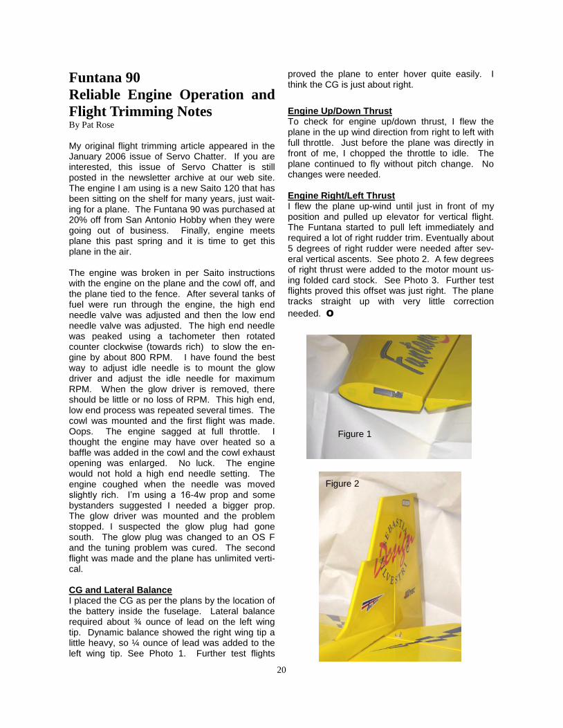
The engine was broken in per Saito instructions with the engine on the plane and the cowl off, and the plane tied to the fence. After several tanks of fuel were run through the engine, the high end needle valve was adjusted and then the low end needle valve was adjusted. The high end needle was peaked using a tachometer then rotated counter clockwise (towards rich) to slow the en-gine by about 800 RPM. I have found the best way to adjust idle needle is to mount the glow driver and adjust the idle needle for maximum RPM. When the glow driver is removed, there should be little or no loss of RPM. This high end, low end process was repeated several times. The cowl was mounted and the first flight was made. Oops. The engine sagged at full throttle. I thought the engine may have over heated so a baffle was added in the cowl and the cowl exhaust opening was enlarged. No luck. The engine would not hold a high end needle setting. The engine coughed when the needle was moved slightly rich. I‘m using a 16-4w prop and some bystanders suggested I needed a bigger prop. The glow driver was mounted and the problem stopped. I suspected the glow plug had gone south. The glow plug was changed to an OS F and the tuning problem was cured. The second flight was made and the plane has unlimited verti-cal. CG and Lateral Balance I placed the CG as per the plans by the location of the battery inside the fuselage. Lateral balance required about ¾ ounce of lead on the left wing tip. Dynamic balance showed the right wing tip a little heavy, so ¼ ounce of lead was added to the left wing tip. See Photo 1. Further test flights
proved the plane to enter hover quite easily. I think the CG is just about right. Engine Up/Down Thrust To check for engine up/down thrust, I flew the plane in the up wind direction from right to left with full throttle. Just before the plane was directly in front of me, I chopped the throttle to idle. The plane continued to fly without pitch change. No changes were needed. Engine Right/Left Thrust I flew the plane up-wind until just in front of my position and pulled up elevator for vertical flight. The Funtana started to pull left immediately and required a lot of right rudder trim. Eventually about 5 degrees of right rudder were needed after sev-eral vertical ascents. See photo 2. A few degrees of right thrust were added to the motor mount us-ing folded card stock. See Photo 3. Further test flights proved this offset was just right. The plane tracks straight up with very little correction
needed. O
Figure 1
Figure 2