
Getting Started Guide - MaxEye Techmaxeyetech.com/...ISDBT_Getting_Started_Guide.pdf · Getting...
40
MaxEye Digital Audio and Video Signal Generation ISDB-T Signal Generation Toolkit Version 2.0.0 Getting Started Guide
Transcript of Getting Started Guide - MaxEye Techmaxeyetech.com/...ISDBT_Getting_Started_Guide.pdf · Getting...

MaxEye Digital Audio and Video Signal Generation
ISDB-T Signal Generation Toolkit
Version 2.0.0
Getting Started Guide
For more information please contact [email protected]
1
Contents
1 Introduction .................................................................................................................................. 3
2 Installed File Location .................................................................................................................. 3
2.1 Soft Front Panel .................................................................................................................... 3
2.2 Programming Examples ........................................................................................................ 3
2.3 Toolkit API VIs..................................................................................................................... 3
2.4 Documentation ...................................................................................................................... 4
3 Soft Front Panel ............................................................................................................................ 4
3.1 MaxEye ISDB-T Signal Generation SFP ............................................................................. 4
3.1.1 Generate and Save Waveform/Generate and Play Waveform ....................................... 5
3.1.2 Play Waveform from File ............................................................................................ 15
3.2 General SFP Controls and Indicators .................................................................................. 18
3.3 Remote Mode ...................................................................................................................... 20
3.3.1 ISDB-T Signal Generator Remote Mode LabVIEW Examples Procedure ................. 21
3.3.2 ISDB-T Signal Generator Remote Mode C Examples Procedure ............................... 26
4 Programming Examples ............................................................................................................. 32
4.1 ISDB-T Signal Generation .................................................................................................. 32
4.1.1 MaxEye ISDB-T RFSG Generate Multiple Frames .................................................... 32
4.1.2 MaxEye ISDBT SG Generate and Save Waveform in File ......................................... 34
4.1.3 MaxEye ISDBT RFSG Play Waveform from File ...................................................... 35
4.1.4 MaxEye ISDBT USRP Play Waveform from File ...................................................... 36
4.1.5 MaxEye ISDBT VST Play Waveform from File ........................................................ 37
5 How to configure parameters for Single Carrier/ Multiple Carriers .......................................... 38

For more information please contact [email protected]
2
5.1 Single Carrier ...................................................................................................................... 38
5.2 Multiple Carrier .................................................................................................................. 38
For more information please contact [email protected]
3
1 Introduction
MaxEye Technologies provides generation functions in LabVIEW and C for generating the
standard complaint signals for various digital audio and video broadcasting standards. This
guide explains how to use the ISDB-T signal generation toolkit using the Soft Front Panel (SFP)
and programming examples by using NI Vector Signal Generator (NI VSG), Vector Signal
Transceiver (NI VST), and Universal Software Radio Peripheral (NI USRP).
Integrated Services Digital Broadcasting - Terrestrial (ISDB-T) is a Japanese standard for digital
terrestrial television and a derivative of ISDB. Developed by the Brazilian government.
2 Installed File Location
2.1 Soft Front Panel
The ISDB-T signal generation soft front panel is located in, C:\Program Files\MaxEye\Digital
Video Toolkits\ISDB-T Generation\SFP
You can also find a shortcut to the above location from the windows start menu.
Start->All Programs->MaxEye->Digital Video Toolkits->ISDB-T
Note: - For Windows 10, Start-> MaxEye.
2.2 Programming Examples
The programming examples are installed in, <LabVIEW>examples\MaxEye\Digital Video
Toolkits\ISDB-T Generation.
You can also find a shortcut to the above location from the windows start menu.
Start->All Programs->MaxEye->Digital Video Toolkits->ISDB-T->Generation
Note: - For Windows 10, Start-> MaxEye.
2.3 Toolkit API VIs
The toolkit APIs are installed in, <LabVIEW>\vi.lib\addons\MaxEye\Digital Video Toolkits
\ISDB-T Generation\Generation\API.
You can also find a shortcut to the above location from the windows start menu.
Start->All Programs->MaxEye->Digital Video Toolkits->ISDB-T
Note: - For Windows 10, Start-> MaxEye.
For more information please contact [email protected]
4
2.4 Documentation
The toolkit help file is installed in, <LabVIEW>\help\MaxEye\Digital Video Toolkits\ MaxEye
ISDBT Signal Generation Help.chm
The toolkit documentation files are installed in, <LabVIEW>\vi.lib\addons\MaxEye\Digital Video
Toolkits\ISDB-T Generation\Generation\Documentation.
You can also find a shortcut to the above location from the windows start menu.
Start->All Programs->MaxEye->Digital Video Toolkits->ISDB-T->Documentation
Note: - For Windows 10, Start-> MaxEye.
3 Soft Front Panel
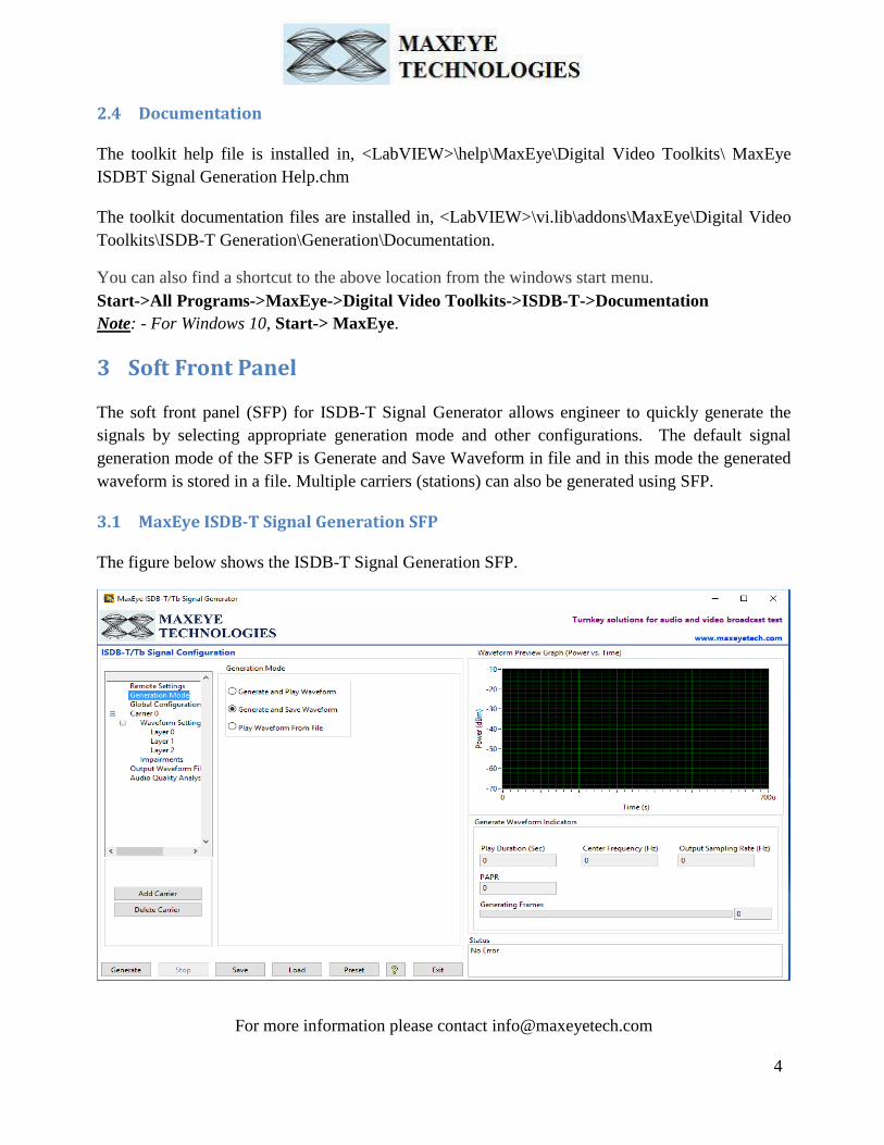
The soft front panel (SFP) for ISDB-T Signal Generator allows engineer to quickly generate the
signals by selecting appropriate generation mode and other configurations. The default signal
generation mode of the SFP is Generate and Save Waveform in file and in this mode the generated
waveform is stored in a file. Multiple carriers (stations) can also be generated using SFP.
3.1 MaxEye ISDB-T Signal Generation SFP
The figure below shows the ISDB-T Signal Generation SFP.

For more information please contact [email protected]
5
3.1.1 Generate and Save Waveform/Generate and Play Waveform
Generate and Play waveform is used to generate ISDB-T signal using hardware. Generate and Save
waveform is used to generate the baseband IQ waveform and store in a file. For this mode hardware
is not required. The Play Waveform from File mode reads the ISDB-T waveform from the file
created using the Generate and Save Waveform and then downloads the waveform to NI RFSG
Memory and then plays the waveform.
Use the Generate and Save Waveform mode
To generate and store the custom waveforms based on your test requirement.
To avoid generating the waveform at the beginning of your test every time. This reduces
your test starting time as some of the signal configuration will take longer to generate the
waveform.
For generating the longer duration waveform as the RFSG memory size is limited.
For testing your receiver for continuous signal reception.
For receiver sensitivity measurement (BER) for longer duration.
Follow the procedure below to generate signals using these generation modes.
1. Select Generation Mode -> Generate and Save Waveform or Generate and Play
Waveform
2. Select Hardware Settings to configure the following parameters.

For more information please contact [email protected]
6
Note: - These settings need not to be configured if the chosen Generation Mode is Generate and
Save Waveform.
Hardware Options – Select hardware as VSG/ VST or USRP.
VSG/ VST
RFSG Resource – Select the Resource Name used in NI Measurement and Automation
Explorer (NI MAX) for the NI PXIe-5672/5673/5673E or NI PXIe 5644R/45R/46R or NI 5840
device.
Power Level (dBm) – Specifies the Average Power level of the signal in dBm.
External Attenuation (dB) – Specifies the external amplification or attenuation, in dB, if
any, between the NI RF signal generator and the device under test. Positive values for this
property represent amplification, and negative values for this property represent attenuation.
Arb: Pre-filter Gain (dB) – Specifies the Arbitrary Waveform Generator (AWG) Pre-filter
Gain, in dB. The pre-filter gain is applied to the waveform data before any other signal
processing. Reduce this value to prevent overflow in the AWG interpolation filters. Other gains
on the NI-RFSG device are automatically adjusted to compensate for non-unity AWG pre-filter
gain.
Software Scaling Factor – Specifies how much to scale the data before writing it with the NI
RFSG. The resulting waveform must be smaller than 1.0 in complex magnitude.
Reference Source – Specifies the source of the Reference Clock signal.
Frequency (Hz) – Specifies the Reference Clock rate, in Hertz (Hz).
Clk Output Terminal – Specifies the terminal where the signal will be exported.
For more information on External Attenuation (dB), Arb: Pre-filter Gain (dB), Reference Source,
Frequency (Hz), Clk Output Terminal, please refer NI RFSG Signal Generators help file.
USRP
USRP IP Address – Configure the IP address of the NI USRP
Gain (dB) – Configure the aggregate gain, in dB, to be applied to the RF signal.
Active Antenna – Configure the antenna port to be used for this channel.
For more information on Active Antenna, Gain (dB), Coerced IQ rate, Coerced Carrier Frequency
and Coerced Gain, please refer NI USRP help file.
The figure below shows the hardware settings for USRP.

For more information please contact [email protected]
7
3. Select Global Configuration to configure the following parameters.

For more information please contact [email protected]
8
Number of Frames – Configure the required number of Transmission Frames. The Number of
Frames property decides the length of waveform to be generated.
Headroom (dB) – Specifies the Headroom value higher than PAPR of the signal to be
generated. For more information, please refer MaxEye ISDB-T Signal Generation Help.chm.
Oversampling Enabled & Output Sampling Rate (Hz) – Use this configuration only when
you want to resample the signal to different sampling rate. The toolkit resamples the generated
signal to a sampling rate equal to the Output Sampling Rate only if the Over Sampling
Enabled property is set to True.
Maximum Real-Time Bandwidth (Hz) – The available bandwidth to combine the multi
carrier waveform based on the selected hardware.
4. Select Carrier to configure the following parameters.
Carrier Frequency (Hz) – Configure the Carrier Frequency for the selected carrier in Hz.
Bandwidth (Hz) – Configure the Bandwidth of the signal for the selected carrier. The toolkit
internally uses the Carrier Frequency and Bandwidth property values internally to compute the
overall bandwidth and sampling rate of the signal when more than one carrier is used.
Note: - By default, the tree control shows Carrier 0. To configure more carriers, click the Add
Carrier button and configure the following parameters for each carrier.
The figure below shows the carrier configuration for each carrier.
For more information please contact [email protected]
9
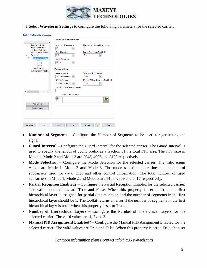
4.1 Select Waveform Settings to configure the following parameters for the selected carrier.
Number of Segments – Configure the Number of Segments to be used for generating the
signal.
Guard Interval – Configure the Guard Interval for the selected carrier. The Guard Interval is
used to specify the length of cyclic prefix as a fraction of the total FFT size. The FFT size in
Mode 1, Mode 2 and Mode 3 are 2048, 4096 and 8192 respectively.
Mode Selection – Configure the Mode Selection for the selected carrier. The valid enum
values are Mode 1, Mode 2 and Mode 3. The mode selection determines the number of
subcarriers used for data, pilot and other control information. The total number of used
subcarriers in Mode 1, Mode 2 and Mode 3 are 1405, 2809 and 5617 respectively.
Partial Reception Enabled? – Configure the Partial Reception Enabled for the selected carrier.
The valid enum values are True and False. When this property is set to True, the first
hierarchical layer is assigned for partial data reception and the number of segments in the first
hierarchical layer should be 1. The toolkit returns an error if the number of segments in the first
hierarchical layer is not 1 when this property is set to True.
Number of Hierarchical Layers – Configure the Number of Hierarchical Layers for the
selected carrier. The valid values are 1, 2 and 3.
Manual PID Assignment Enabled? – Configure the Manual PID Assignment Enabled for the
selected carrier. The valid values are True and False. When this property is set to True, the user

For more information please contact [email protected]
10
needs to assign the PIDs for each Hierarchical layer. The toolkit ignores this property if the
value for Payload Mode property is set to other than MPEG2TS File(s) mode.
TS File Format – Configure the TS File Format for the selected carrier. The valid values for
this property are TS File and Remultiplexed TS File. The toolkit internally uses this property
only if the Manual PID Assignment Enabled property is set to True.
Payload Mode – Configure various payload settings. The possible payload options are
o PN Sequence – Configure the Sync Insertion Enabled, Payload PN Order, PN Seed
properties. The toolkit generates pseudo random sequence based on the PN Order and Seed
value. The generated bit sequence is used as a payload for generating the signal. Use this
mode for testing the receiver performance for random payload values. When the number of
super frames is more than 1 then the toolkit maintains payload continuity across the super
frames. The below parameters need to be configured in layer configuration.
o User defined bits – Configure Sync Insertion Enabled and Payload User Defined Bits
properties. Specifies a bit pattern as an array of ones and zeros. If the array length is greater
than the required payload length, the toolkit uses a subset of the required length from the
beginning of the array for waveform generation. If the array length is less than the required
payload length, the toolkit repeats the bit pattern until the required length is achieved.
o Test Pattern – Configure Sync Insertion Enabled and Payload Test Pattern properties.
The possible values for the Test Pattern are All 1s, All 0s, 10101010 and 01010101. This
mode is used for generating signal with known test patterns. The below parameters need to
be configured in layer configuration.
o Test File – Configure the Sync Insertion Enabled and Payload File Path properties. This
mode is used for generating signal with the binary data from the file. The below parameters
need to be configured in layer configuration.
o MPEG2TS File(s) – In this mode configure the MPEG2 TS Number of TS Files and
MPEG2 TS File Path property.
If the Sync Insertion Enabled property is set to True, the toolkit inserts MPEG2 TS packet sync
byte (0x47) after every 187 bytes. The length of the TS packet is 188 bytes and the first byte is

For more information please contact [email protected]
11
a sync byte (0x47).
Note: - Except for MPEG2TS File(s) mode the other payload properties should be
configured for each layer separately.
MPEG2 TS Number of TS Files – Configure the Number of MPEG2 TS Number of Files for
the selected carrier.
MPEG2 TS File Path – Select the MPEG2 TS File based on the number of TS files configured
for the selected carrier.
4.2 Select Layer Configuration to configure the following parameters for the selected carrier.
Note: - Based on the Payload Mode selection in Waveform Settings corresponding Payload settings
are visible in Layer Configuration.

For more information please contact [email protected]
12
Number of Segments in Layer– Configure the Number of Segments in layer for the selected
layer. The total number of used segments in all the layers should be less than or equal to the
value configured in the Number of Segments property. The toolkit returns an error if the total
number of segments in all the layer exceeds the Number of Segments.
Coding Rate – Select one of the coding rate as per the requirement. Supporting coding rates
are 1/2, 2/3, 3/4, 5/6 and 7/8.
Modulation Scheme – Select one of the Modulation Scheme as per the requirement.
Supporting schemes are DQPSK, QPSK, 16 - QAM and 64 QAM.
Time Interleaving Length Mode 1 – Select one of the Time Interleaving Length Mode values
as per the requirement. Supporting values are 0, 4, 8 and 16.
Time Interleaving Length Mode 2 – Select one of the Time Interleaving Length Mode values
as per the requirement. Supporting values are 0, 2, 4 and 8.
Time Interleaving Length Mode 3 – Select one of the Time Interleaving Length Mode values
as per the requirement. Supporting values are 0, 1, 2 and 4.
Note: - Based on the Mode selection in Waveform Settings, Time Interleaving Length Modes
are visible in Layer Configuration.
Assigned PIDs – Configure Assigned PIDs of the selected TS File for each layer. This Control
is visible only if the Payload Mode selected as a MPEG2 TS File format.
Payload Test Pattern – Select the required Test Pattern. Configure this field when the Payload
mode is Test Pattern.
Payload User Defined Bits – Configure Payload User Defined Bits for each layer. This
Control is visible only if the Payload Mode selected as a User Defined Bits format.
Payload File Path – Configure the Payload File Path properties and the toolkit ignores other
properties available in the Payload settings/ Digital Video Payload Control. This mode is used
for generating signal with the data from the file. This Control is visible only if the Payload
Mode selected as a Test File format.
Payload PN Order – Specifies the order of the PN bit sequence to be generated. The valid
values are 5 to 31, inclusive. Configure this field when the Payload mode is PN sequence.
Payload PN Seed – Specifies the initial state of the PN generator shift register. Configure this
field when the Payload mode is PN Sequence.
4.3 Select Impairments to configure the following parameters for the selected carrier.
Impairments Enabled - If this property is set to True then the toolkit adds the impairments to
the generated signal as per the user configuration for the supported impairments.
Note: - If Impairments Enabled is True, then the following parameters are enabled in the SFP
otherwise the controls are disabled and grayed out.

For more information please contact [email protected]
13
Clock Offset (PPM) - The toolkit applies the clock offset to the generated waveform based on
this value. The applied clock offset is relative to the clock frequency of the signal generator.
The default value is 0.
Frequency Offset, Hz- The toolkit applies frequency offset to the created waveform based on
the value configured in this property. The applied frequency offset is relative to the signal
generator's carrier frequency. The default value is 0.
Quadrature skew- Quadrature Skew specifies the deviation in angle from 90 degrees between
the in-phase (I) and quadrature-phase (Q) signals. The default value for the Quadrature Skew is
0.
IQ gain imbalance, dB- This value specifies the ratio, in dB, of the mean amplitude of the in-
phase (I) signal to the mean amplitude of the quadrature-phase (Q) signal. The default value is
0.

For more information please contact [email protected]
14
I DC offset, %- The toolkit adds the DC offset to the in-phase signal component (I) of the
complex waveform as a percentage of the root mean square magnitude of the unaltered I signal.
The default value is 0.
Q DC Offset, %- The toolkit adds the DC offset to the quadrature-phase signal component (Q)
of the complex waveform as a percentage of the root mean square magnitude of the unaltered Q
signal. The default value is 0.
AWGN Enabled- If this property is set to True then the toolkit adds Additive White Gaussian
Noise (AWGN) to the created waveform based on the value configured in the Carrier to Noise
Ratio property.
Carrier to Noise Ratio, dB- This value specifies the Carrier to Noise ratio of the generated
signal. The default value is 40dB.
4.4 Select Output Waveform Settings to configure the following parameters to save output
waveform in a file.
Sample Width – The default sample width of the output waveform is 16-bits. The available
options are 8-bits and 16-bits. We recommend using 16-bits sample width for better signal
quality of the generated waveform.
Waveform File Path- Select a path to save the waveform.
Note: - Needs to be configured only when the generation mode is Generate and Save waveform.

For more information please contact [email protected]
15
3.1.2 Play Waveform from File
In this generation mode ISDB-T Signal Generator reads the waveform from the file created using
the Generate and Save waveform generation mode, explained in the section 3.1.1 of this section,
and then downloads the waveform in real-time to NI RFSG Memory and then plays the waveform.
This example is created using the NI RFSG streaming example available in the NI website.
This example uses NI RFSG in streaming mode for playing the waveform in real-time. The
performance of this example is related to the performance of the CPU and available RAM memory.
Follow the procedure below to generate waveform using this generation mode
1. Select Generation Mode -> Play Waveform from File
2. Select Hardware Settings to configure the following parameters.
Hardware Options – Select hardware as VSG/ VST or USRP.
Refer section 3.1.1 of this document to configure the desired hardware.
For more information please contact [email protected]
16
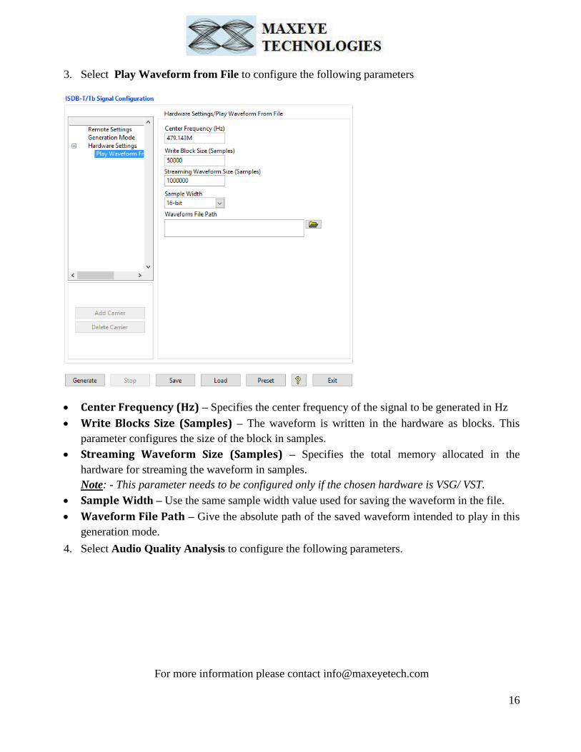
3. Select Play Waveform from File to configure the following parameters
Center Frequency (Hz) – Specifies the center frequency of the signal to be generated in Hz
Write Blocks Size (Samples) – The waveform is written in the hardware as blocks. This
parameter configures the size of the block in samples.
Streaming Waveform Size (Samples) – Specifies the total memory allocated in the
hardware for streaming the waveform in samples.
Note: - This parameter needs to be configured only if the chosen hardware is VSG/ VST.
Sample Width – Use the same sample width value used for saving the waveform in the file.
Waveform File Path – Give the absolute path of the saved waveform intended to play in this
generation mode.
4. Select Audio Quality Analysis to configure the following parameters.

For more information please contact [email protected]
17
DSA Resource Name – Configure the resource name used in NI Measurement and
Automation explorer for the DAQmx.
Audio Measurements? – Configure the audio measurements as a true to measure the audio
quality analysis.
Channel Index – Corresponds to audio channel, based on this measurement traces desired
audio channels are displayed.
Audio Settings – The Audio Settings for Audio Analyzer contains Configures the Audio
Settings property of the Audio Signal Analysis handle. This Configuration gives the
information about Audio tone and channels to analyze.
Number of Channels – Number of Audio Channels to Analyze.

For more information please contact [email protected]
18
Reference Channel – The Audio Channel to be analyzed.
Fundamental Frequency [Hz] – The Input Single tone signal that was generated in the all of
the audio channel.
Sampling Rate [Hz] – Audio Signal sampling rate.
Number Harmonics – Number Harmonic tones to be considered for Analysis.
Acquisition Length – Configure the Acquisition Length in seconds, length in sec for which
Audio Analysis measurements are carried out.
Phase Shift Enabled – If Phase shift Enabled is true then Phase Shift Measurements are
performed on the audio Channels or else Phase Shift Measurements are disabled.
Crosstalk Enabled – If Crosstalk Enabled is true then Crosstalk Measurements are performed
on the audio Channels or else Crosstalk Measurements are disabled.
3.2 General SFP Controls and Indicators
Add carrier – Click to add new carrier configuration with default values.
Delete Carrier – Click to delete the selected carrier. Click on the appropriate carrier tag in a
tree control or on any child tag like waveform settings, impairments, service configuration
under specific parent carrier tag (carrier 0, carrier 1 etc.) to select which carrier is going be
deleted.
Note: - One carrier configuration is default which can’t be deleted.
All the items under the parent carrier tag specify configuration that need to be configured for
each and every unique carrier.
Generate - Click to generate signal as per the parameters configured.
Note: - Parameters can be changed at run time ones Generate button has been pressed.
Stop – Click to stop the signal generation.
Save – Saves the entire configuration in the binary file.
Load – Load the entire configuration back to the application which has been saved previously
by Clicking Save button.
Preset – Click to reinitialize all parameters to their defaults values.
Exit – Click to exit the application.
For more information please contact [email protected]
19
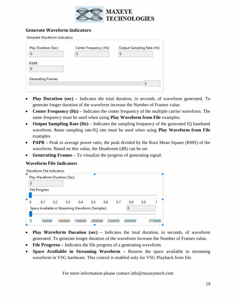
Generate Waveform Indicators
Play Duration (sec) – Indicates the total duration, in seconds, of waveform generated. To
generate longer duration of the waveform increase the Number of Frames value.
Center Frequency (Hz) – Indicates the center frequency of the multiple carrier waveform. The
same frequency must be used when using Play Waveform from File examples.
Output Sampling Rate (Hz) – Indicates the sampling frequency of the generated IQ baseband
waveform. Same sampling rate/IQ rate must be used when using Play Waveform from File
examples.
PAPR – Peak to average power ratio, the peak divided by the Root Mean Square (RMS) of the
waveform. Based on this value, the Headroom (dB) can be set.
Generating Frames – To visualize the progress of generating signal.
Waveform File Indicators
Play Waveform Duration (sec) – Indicates the total duration, in seconds, of waveform
generated. To generate longer duration of the waveform increase the Number of Frames value.
File Progress – Indicates the file progress of a generating waveform.
Space Available in Streaming Waveform – Returns the space available in streaming
waveform in VSG hardware. This control is enabled only for VSG Playback from file.

For more information please contact [email protected]
20
Audio Analysis Indicators
Returns the audio analysis output parameters Channel Measurements, Harmonic Components,
Crosstalk and Phase shift.
Status – Displays warning or error.
3.3 Remote Mode
Remote mode allows user to control the MaxEye ISDB-T/Tb Signal Generator remotely using
programming examples (LabVIEW or C) to generate signals. The programming examples and APIs
are provided with the ISDB-T/Tb signal generation toolkit.
Follow the below procedure in SFP to run the ISDB-T/Tb Signal Generator in Remote Mode
1. Select Remote Settings to configure the following parameters
Remote Mode? – Turn Remote Mode? switch ON (Remote) or OFF (Local) as required. The
glowing yellow LED indicates ON state of the switch. By default, the Remote Mode? switch is
in OFF state.
Port Number – Configure this control if Remote Mode is ON. Both client (MaxEye DRM
Radio Generator) and server application must have same port number. The default Port Number
is 7070.
Timeout (ms) – Configure this control if Remote Mode is ON. Timeout specifies the time in
milliseconds that the client waits for a connection to be established with the server application.
If a connection is not established in the specified time, the MaxEye Universal Radio Generator
returns an error. The default Timeout is 20 seconds.

For more information please contact [email protected]
21
3.3.1 ISDB-T Signal Generator Remote Mode LabVIEW Examples Procedure
3.3.1.1 ISDB-T Generate Multiple Frames
Follow the below procedure to configure the example
1. Find the ISDB-T LabVIEW Remote example in, <LabVIEW>examples\MaxEye\Digital Video
Toolkits\ISDB-T Generation\Remote
2. Open MaxEye ISDBT RFSG Remote Generate Multiple Frames.vi
3. The user configurations are organized into the following categories displayed in multiple Tabs
Network Settings
Hardware Configuration
Global Configuration
Carrier Configuration
ISDB-T Configuration
Layer Configuration
Impairments
Navigate to the Network Settings tab to configure the following parameters
For more information please contact [email protected]
22
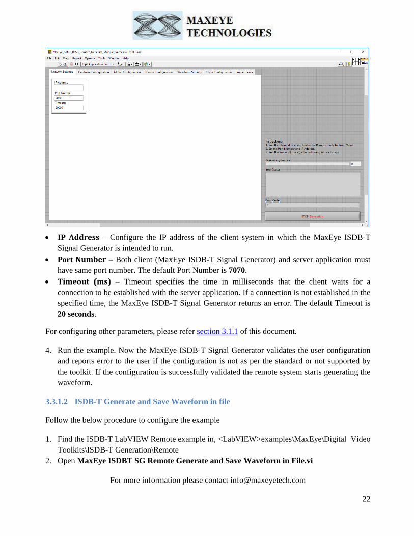
IP Address – Configure the IP address of the client system in which the MaxEye ISDB-T
Signal Generator is intended to run.
Port Number – Both client (MaxEye ISDB-T Signal Generator) and server application must
have same port number. The default Port Number is 7070.
Timeout (ms) – Timeout specifies the time in milliseconds that the client waits for a
connection to be established with the server application. If a connection is not established in the
specified time, the MaxEye ISDB-T Signal Generator returns an error. The default Timeout is
20 seconds.
For configuring other parameters, please refer section 3.1.1 of this document.
4. Run the example. Now the MaxEye ISDB-T Signal Generator validates the user configuration
and reports error to the user if the configuration is not as per the standard or not supported by
the toolkit. If the configuration is successfully validated the remote system starts generating the
waveform.
3.3.1.2 ISDB-T Generate and Save Waveform in file
Follow the below procedure to configure the example
1. Find the ISDB-T LabVIEW Remote example in, <LabVIEW>examples\MaxEye\Digital Video
Toolkits\ISDB-T Generation\Remote
2. Open MaxEye ISDBT SG Remote Generate and Save Waveform in File.vi
For more information please contact [email protected]
23
3. The user configurations are Organized into the following categories displayed in multiple Tabs
Network Settings
Global Configuration
Carrier Configuration
ISDB-T Configuration
Layer Configuration
Impairments
Navigate to the Network Settings tab to configure the following parameters
IP Address – Configure the IP address of the client system in which the MaxEye ISDB-T
Signal Generator is intended to run.
Port Number – Both client (MaxEye ISDB-T Signal Generator) and server application must
have same port number. The default Port Number is 7070.
Timeout (ms) – Timeout specifies the time in milliseconds that the client waits for a
connection to be established with the server application. If a connection is not established in the
specified time, the MaxEye ISDB-T Signal Generator returns an error. The default Timeout is
20 seconds.
For configuring other parameters, please refer section 3.1.1 of this document.
4. Run the example. Now the MaxEye ISDB-T Signal Generator validates the user configuration
and reports error to the user if the configuration is not as per the standard or not supported by

For more information please contact [email protected]
24
the toolkit. If the configuration is successfully validated the remote system starts generating the
waveform.
3.3.1.3 ISDBT VSG VST Play Waveform from File
Follow the below procedure to configure the example
1. Find the ISDB-T LabVIEW Remote example in, <LabVIEW>examples\MaxEye\Digital Video
Toolkits\ISDB-T Generation\Remote
2. Open MaxEye ISDBT SG Remote VSG VST Play Waveform from File.vi
3. The user configurations are Organized into the following categories displayed in multiple Tabs
Network Settings
Hardware Configuration
Play Waveform Settings
Navigate to the Network Settings tab to configure the following parameters
IP Address – Configure the IP address of the client system in which the MaxEye ISDB-T
Signal Generator is intended to run.
Port Number – Both client (MaxEye ISDB-T Signal Generator) and server application must
have same port number. The default Port Number is 7070.
Timeout (ms) – Timeout specifies the time in milliseconds that the client waits for a
connection to be established with the server application. If a connection is not established in the
specified time, the MaxEye ISDB-T Signal Generator returns an error. The default Timeout is
20 seconds.

For more information please contact [email protected]
25
For configuring other parameters, please refer section 3.1.1 of this document.
4. Run the example. Now the MaxEye ISDB-T Signal Generator validates the user configuration
and reports error to the user if the configuration is not as per the standard or not supported by
the toolkit. If the configuration is successfully validated the remote system starts generating the
waveform.
3.3.1.4 ISDBT USRP Play Waveform from File
Follow the below procedure to configure the example
1. Find the ISDB-T LabVIEW Remote example in, <LabVIEW>examples\MaxEye\Digital Video
Toolkits\ISDB-T Generation\Remote
2. Open MaxEye ISDBT SG Remote USRP Play Waveform from File.vi
3. The user configurations are Organized into the following categories displayed in multiple Tabs
Network Settings
Hardware Configuration
Play Waveform Settings
Navigate to the Network Settings tab to configure the following parameters
IP Address – Configure the IP address of the client system in which the MaxEye ISDB-T
Signal Generator is intended to run.
Port Number – Both client (MaxEye ISDB-T Signal Generator) and server application must
have same port number. The default Port Number is 7070.

For more information please contact [email protected]
26
Timeout (ms) – Timeout specifies the time in milliseconds that the client waits for a
connection to be established with the server application. If a connection is not established in the
specified time, the MaxEye ISDB-T Signal Generator returns an error. The default Timeout is
20 seconds.
For configuring other parameters, please refer section 3.1.1 of this document.
4. Run the example. Now the MaxEye ISDB-T Signal Generator validates the user configuration
and reports error to the user if the configuration is not as per the standard or not supported by
the toolkit. If the configuration is successfully validated the remote system starts generating the
waveform.
3.3.2 ISDB-T Signal Generator Remote Mode C Examples Procedure
3.3.2.1 ISDB-T Generate Multiple Frames
Follow the below procedure to configure the example
1. Find the Remote C examples in, C:\Program Files (x86)\MaxEye\Digital Video Toolkits\
ISDB-T Generation\Generation\C\Generate Multiple Frames
2. Open the desired example directory and open the solution file Generate Multiple Frames.jsln
in Microsoft visual C++.
3. Navigate to MaxEye ISDB-T Generate and Play Init.c from the solution explorer.
For more information please contact [email protected]
27
4. Configure the parameters listed as required. For help, please follow the comments given against
each configuration parameter.
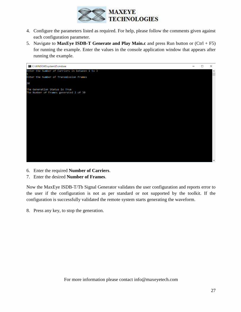
5. Navigate to MaxEye ISDB-T Generate and Play Main.c and press Run button or (Ctrl + F5)
for running the example. Enter the values in the console application window that appears after
running the example.
6. Enter the required Number of Carriers.
7. Enter the desired Number of Frames.
Now the MaxEye ISDB-T/Tb Signal Generator validates the user configuration and reports error to
the user if the configuration is not as per standard or not supported by the toolkit. If the
configuration is successfully validated the remote system starts generating the waveform.
8. Press any key, to stop the generation.

For more information please contact [email protected]
28
3.3.2.2 ISDB-T Generate and Save Waveform
Follow the below procedure to configure the example
1. Find the C example in, C:\Program Files (x86)\MaxEye\Digital Video Toolkits\ ISDB-T
Generation\Generation\C\Generate and Save Waveform
2. Open the desired example directory and open the solution file Generate and Save.jsln in
Microsoft visual C++.
3. Navigate to MaxEye ISDB-T Generate and Save Init.c from the solution explorer.
4. Configure the parameters listed as required. For help, please follow the comments given against
each configuration parameter.
5. Navigate to MaxEye ISDB-T Generate and Save Main.c and press Run button or (Ctrl + F5)
for running the example. Enter the values in the console application window that appears after
running the example.

For more information please contact [email protected]
29
6. Enter the required Number of Carriers.
7. Enter the desired Number of Frames.
Now the MaxEye ISDB-T/Tb Signal Generator validates the user configuration and reports error to
the user if the configuration is not as per standard or not supported by the toolkit. If the
configuration is successfully validated the remote system starts generating the waveform.
8. Press any key, to stop the generation.
3.3.2.3 ISDBT VSG VST Play Waveform from File
Follow the below procedure to configure the example

For more information please contact [email protected]
30
1. Find the C example in, C:\Program Files (x86)\MaxEye\Digital Video Toolkits\ ISDB-T
Generation\Generation\C \VSG VST Play Waveform from File
2. Open the desired example directory and open the solution file MaxEye VSG VST Play
Waveform.jsln in Microsoft visual C++.
3. Navigate to MaxEye ISDB-T VSG VST Play Waveform Init.c from the solution explorer.
4. Configure the parameters listed as required. For help, please follow the comments given against
each configuration parameter.
5. Navigate to MaxEye ISDB-T VSG VST Play Waveform Main.c and press Run button or
(Ctrl + F5) for running the example. Enter the values in the console application window that
appears after running the example.
Now the MaxEye ISDB-T/Tb Signal Generator validates the user configuration and reports error to
the user if the configuration is not as per standard or not supported by the toolkit. If the
configuration is successfully validated the remote system starts generating the waveform.
6. Press any key, to stop the generation.
For more information please contact [email protected]
31
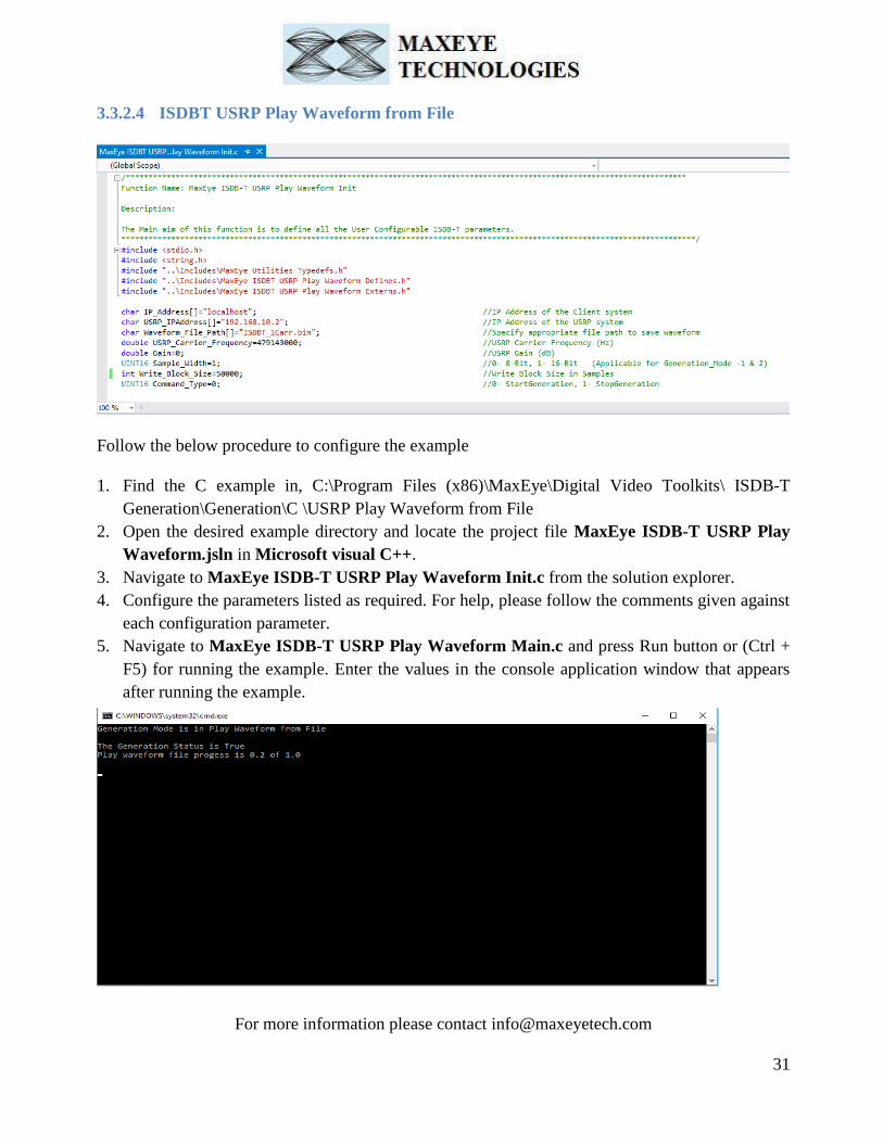
3.3.2.4 ISDBT USRP Play Waveform from File
Follow the below procedure to configure the example
1. Find the C example in, C:\Program Files (x86)\MaxEye\Digital Video Toolkits\ ISDB-T
Generation\Generation\C \USRP Play Waveform from File
2. Open the desired example directory and locate the project file MaxEye ISDB-T USRP Play
Waveform.jsln in Microsoft visual C++.
3. Navigate to MaxEye ISDB-T USRP Play Waveform Init.c from the solution explorer.
4. Configure the parameters listed as required. For help, please follow the comments given against
each configuration parameter.
5. Navigate to MaxEye ISDB-T USRP Play Waveform Main.c and press Run button or (Ctrl +
F5) for running the example. Enter the values in the console application window that appears
after running the example.

For more information please contact [email protected]
32
Now the MaxEye ISDB-T/Tb Signal Generator validates the user configuration and reports error to
the user if the configuration is not as per standard or not supported by the toolkit. If the
configuration is successfully validated the remote system starts generating the waveform.
6. Press any key, to stop the generation.
4 Programming Examples
The ISDB-T Signal generation toolkit contains examples for performing the following i. Creating the waveform based on the standard specific user input parameters and then
downloads the waveform to NI VSG/NI VST.
ii. Creating the waveform based on the standard specific user input parameters and then writes
the waveform to the file.
iii. Playing the waveform using NI VSG, NI VST and NI USRP.
The programming examples are created using the Labview API VIs. For more information about
the API VI used in the example VIs refer to the MaxEye ISDB-T Signal Generation Help.chm
document, accessible at
Start ->All Programs->MaxEye->Digital Video Toolkits-> ISDB-T ->Documentation.
4.1 ISDB-T Signal Generation
The ISDB-T is a Japanese standard for digital terrestrial television and a derivative of ISDB,
ISDB-T is developed by the Brazilian government and is being widely adopted in South
America. ISDB-T standard supports hierarchical transmission to support both partial reception,
fixed and mobile reception. Each hierarchical layer consists of one or more OFDM segments and
parameters such as the carrier modulation scheme, inner-code coding rate, and time interleaving
length can be specified for each hierarchical layer. The standard supports up to 3 hierarchical
layers including the partial reception hierarchical layer which is transmitted in one segment.
4.1.1 MaxEye ISDB-T RFSG Generate Multiple Frames
This Example is used to generate multiple Transmission Frames. TS stream is used for
generating the signal for ISDB-T waveforms. The figure below shows the front panel of the
Example VI.

For more information please contact [email protected]
33
The user configurations are divided into following categories displayed in multiple Tabs
Hardware Configuration
Global Configuration
Carrier Configuration
ISDB-T Configuration
Layer Configuration
Impairments Configuration
Please refer section 3.1.1 of this document for the configuration procedure and control details.
How to Configure for Single Carrier/ Multiple Carriers
Please refer section 6 of this document for information on configuring for Single Carrier and
Multiple Carriers.
After configuring all the parameters, run the example to start generating the waveform. Press Stop
to stop generation at any time. Error dialog box pops up to the user if any error occurs. The user can
click either Continue or Stop from the error dialog box to abort the generation.
Indicators
Please refer section 3.2 of this document for the indicator details.

For more information please contact [email protected]
34
4.1.2 MaxEye ISDBT SG Generate and Save Waveform in File
This Example is used to generate multiple ISDB-T transmission frames and the generated
waveform is stored in a file for play back. The figure below shows the front panel of the Example
VI.
The user configurations are divided into following categories displayed in multiple Tabs
Global Configuration
Carrier Configuration
ISDB-T Configuration
Layer Configuration
Impairments Configuration
Please refer section 3.1.1 of this document for the configuration procedure and control details.
Maximum Real Time Bandwidth – The available bandwidth to combine the multi carrier
waveform based on the selected hardware.
Please refer section 5.1.1 of this document for the other indicator details in the example.
How to Configure for Single Carrier/ Multiple Carriers
Please refer section 6 of this document for information on configuring for Single Carrier and
Multiple Carriers.
For more information please contact [email protected]
35
After configuring all the parameters, run the example to start generating the waveform. Press Stop
to stop generation at any time. Error dialog box pops up to the user if any error occurs. The user can
click either Continue or Stop from the error dialog box to abort the generation.
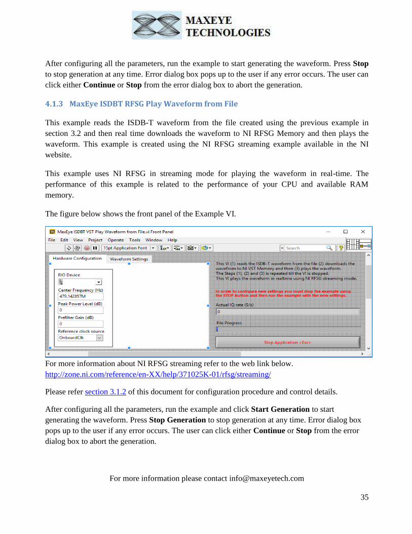
4.1.3 MaxEye ISDBT RFSG Play Waveform from File
This example reads the ISDB-T waveform from the file created using the previous example in
section 3.2 and then real time downloads the waveform to NI RFSG Memory and then plays the
waveform. This example is created using the NI RFSG streaming example available in the NI
website.
This example uses NI RFSG in streaming mode for playing the waveform in real-time. The
performance of this example is related to the performance of your CPU and available RAM
memory.
The figure below shows the front panel of the Example VI.
For more information about NI RFSG streaming refer to the web link below.
http://zone.ni.com/reference/en-XX/help/371025K-01/rfsg/streaming/
Please refer section 3.1.2 of this document for configuration procedure and control details.
After configuring all the parameters, run the example and click Start Generation to start
generating the waveform. Press Stop Generation to stop generation at any time. Error dialog box
pops up to the user if any error occurs. The user can click either Continue or Stop from the error
dialog box to abort the generation.
For more information please contact [email protected]
36
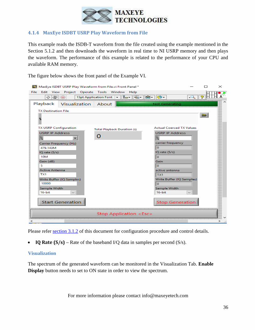
4.1.4 MaxEye ISDBT USRP Play Waveform from File
This example reads the ISDB-T waveform from the file created using the example mentioned in the
Section 5.1.2 and then downloads the waveform in real time to NI USRP memory and then plays
the waveform. The performance of this example is related to the performance of your CPU and
available RAM memory.
The figure below shows the front panel of the Example VI.
Please refer section 3.1.2 of this document for configuration procedure and control details.
IQ Rate (S/s) – Rate of the baseband I/Q data in samples per second (S/s).
Visualization
The spectrum of the generated waveform can be monitored in the Visualization Tab. Enable
Display button needs to set to ON state in order to view the spectrum.

For more information please contact [email protected]
37
4.1.5 MaxEye ISDBT VST Play Waveform from File
This example reads the ISDB-T waveform from the file created using the example mentioned in the
Section3.2. This example deploys the bit file dynamically to the respective target (FPGA) and
configures a stream from the Host to the FPGA target and writes waveform data to the streaming
DMA FIFO.
The figure below shows the front panel of the Example VI.

For more information please contact [email protected]
38
Please refer section 3.1.2 of this document for configuration procedure and control details.
After configuring all the parameters, run the example and click Start Generation to start generating
the waveform. Press Stop Generation to stop generation at any time. Error dialog box pops up to the
user if any error occurs. The user can click either Continue or Stop from the error dialog box to
abort the generation.
Indicators
Actual IQ Rate (S/s) – Rate of the baseband I/Q data in samples per second (S/s).
File Progress – To visualize the progress of generating signal.
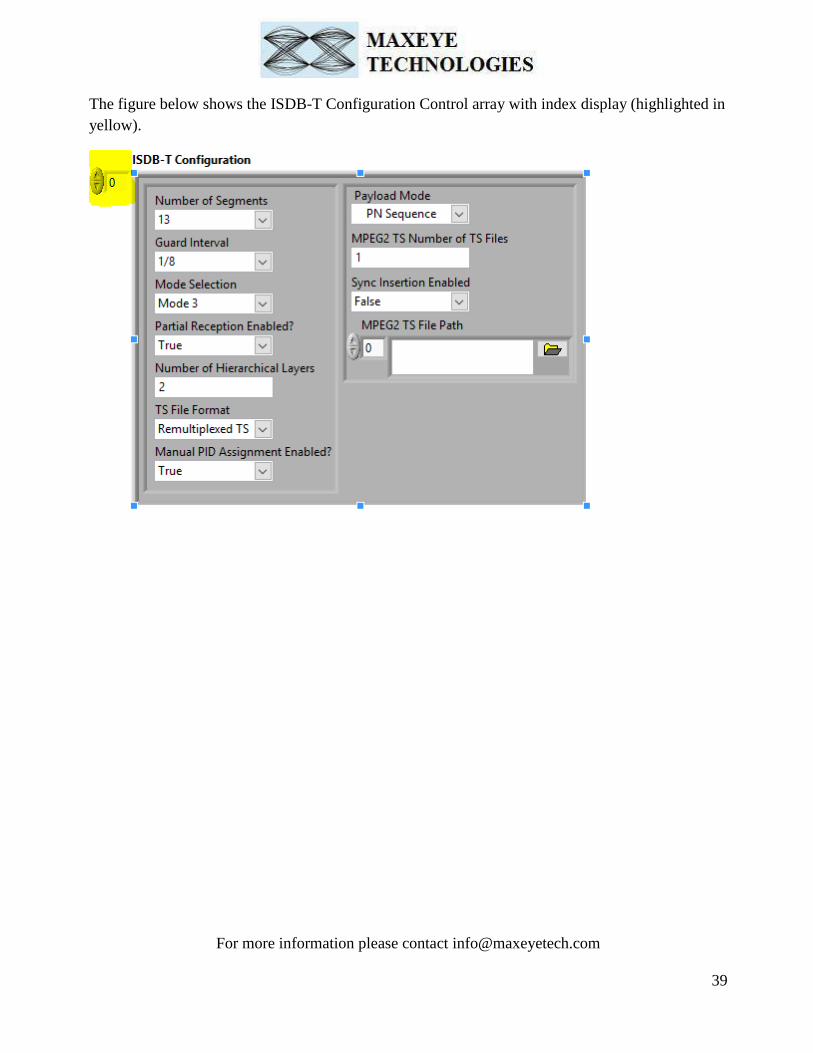
5 How to configure parameters for Single Carrier/ Multiple
Carriers
The controls in the Carrier Configuration, ISDB-T Configuration, Layer Configuration and
Impairments are configured for each carrier. Hence the controls are given in an array where each
element corresponds to one carrier. Since the index value starts from 0, the index 0 corresponds to
1st carrier, index 1 corresponds to 2
nd carrier and so on.
5.1 Single Carrier
For single carrier configuration, configure only index 0 of the above controls.
5.2 Multiple Carrier
For multiple carriers, use the index display to navigate through different elements and configure for
the required number of carriers. For N carriers, configure upto index N-1.
For more information please contact [email protected]
39
The figure below shows the ISDB-T Configuration Control array with index display (highlighted in
yellow).


![Skaffold - storage.googleapis.com · [getting-started getting-started] Hello world! [getting-started getting-started] Hello world! [getting-started getting-started] Hello world! 5.](https://static.fdocuments.in/doc/165x107/5ec939f2a76a033f091c5ac7/skaffold-getting-started-getting-started-hello-world-getting-started-getting-started.jpg)