Engineering\CADD Systems Office CADD Manager's Series Customizing the Interface.
Upload
duongkhuongCategory
view
232download
0
Version 11.1
Part Number: Aspen Plus® 11.1September 2001Copyright (c) 1981-2001 by Aspen Technology, Inc. All rights reserved.
Aspen Plus®, Aspen Properties®, Aspen Engineering Suite, AspenTech®, ModelManager, the aspen leaf logo andPlantelligence are trademarks or registered trademarks of Aspen Technology, Inc., Cambridge, MA.
BATCHFRAC and RATEFRAC are trademarks of Koch Engineering Company, Inc.
All other brand and product names are trademarks or registered trademarks of their respective companies.
This manual is intended as a guide to using AspenTech's software. This documentation contains AspenTechproprietary and confidential information and may not be disclosed, used, or copied without the prior consent ofAspenTech or as set forth in the applicable license agreement. Users are solely responsible for the proper use of thesoftware and the application of the results obtained.
Although AspenTech has tested the software and reviewed the documentation, the sole warranty for the software maybe found in the applicable license agreement between AspenTech and the user. ASPENTECH MAKES NOWARRANTY OR REPRESENTATION, EITHER EXPRESSED OR IMPLIED, WITH RESPECT TO THISDOCUMENTATION, ITS QUALITY, PERFORMANCE, MERCHANTABILITY, OR FITNESS FOR APARTICULAR PURPOSE.
CorporateAspen Technology, Inc.Ten Canal ParkCambridge, MA 02141-2201USAPhone: (1) (617) 949-1021Toll Free: (1) (888) 996-7001Fax: (1) (617) 949-1724URL: http://www.aspentech.com
DivisionDesign, Simulation and Optimization SystemsAspen Technology, Inc.Ten Canal ParkCambridge, MA 02141-2201USAPhone: (617) 949-1000Fax:(617) 949-1030

Getting Started Customizing Unit Operation Models Contents •••• iii
Contents
About This ManualSessions in this Manual ....................................................................................................1-2Files Created in these Sessions.........................................................................................1-3Integration Features for Custom Unit Operation Models.................................................1-4Aspen Plus Excel Unit Operations ...................................................................................1-4Aspen Plus Fortran Models ..............................................................................................1-5Creating GUI forms for Proprietary Models ....................................................................1-5Supporting Files ...............................................................................................................1-5Related Documentation ....................................................................................................1-6
Getting Started Guides .........................................................................................1-6Installation Guide .................................................................................................1-6User Guides ..........................................................................................................1-6
Technical Support ............................................................................................................1-7World Wide Web .................................................................................................1-7Online Technical Support Center .........................................................................1-7Phone and e-mail ..................................................................................................1-8
Creating an Excel Unit Operation ModelDefining the Simulation ...................................................................................................2-2Setting Up the Model in Aspen Plus ................................................................................2-3
Build the Process Flowsheet ................................................................................2-3Enter Title, Components, Base Method, and Feed Specifications .......................2-3Enter Excel Path and User Array Data .................................................................2-5Setup a Product Stream Flash...............................................................................2-6
Setting Up the Excel Model .............................................................................................2-7Copy and Examine the Excel Template ...............................................................2-7Edit the Excel Sheets............................................................................................2-8Enter Membrane Model Equations and Parameters ...........................................2-10
Running the Excel Model...............................................................................................2-11Results from the Excel Model........................................................................................2-14
Customizing the Excel/Aspen Plus InterfaceRevising the Excel Model ................................................................................................3-2Revising the User Subroutine...........................................................................................3-4Code Listing – Subroutine MEM2 ...................................................................................3-5

iv •••• Contents Getting Started Customizing Unit Operation Models
Code Description – Subroutine MEM2..........................................................................3-12Compiling and Linking the Subroutine ..........................................................................3-14
Compile the Excel Interface Subroutine ............................................................3-14Create a Shared Library......................................................................................3-15
Running the Simulation..................................................................................................3-16Results from the Custom Excel Model ..........................................................................3-18
Customizing the Aspen Plus Model LibraryCreating a Model Library .................................................................................................4-2
Create an Empty Custom Model Library .............................................................4-2Create a Template for Your Custom Model.........................................................4-3Create the Custom Model from the Template......................................................4-4
Editing the Custom Model ...............................................................................................4-8Create a Custom Icon ...........................................................................................4-9Create References to the Real and Integer Parameters.......................................4-11
Inserting the New Model and Running the Simulation..................................................4-12Insert the New Model .........................................................................................4-12Check and Edit Setup Sheets..............................................................................4-13Compile, Link, and Run .....................................................................................4-14
Creating an Aspen Plus Fortran ModelPutting the Model Equations in the User Subroutine.......................................................5-2Code Listing – Subroutine HFUM ...................................................................................5-2Code Description – Subroutine HFUM............................................................................5-6Compiling and Linking the Subroutine ............................................................................5-9Running the Simulation..................................................................................................5-10Results from the Custom Fortran Model........................................................................5-11
Creating an Aspen Plus Custom FormSetting Up the Visual Basic Environment........................................................................6-2Creating the Visual Basic Form .......................................................................................6-4
Create Three Named Controls..............................................................................6-4Build the Tab Control...........................................................................................6-5Build the Input Control ........................................................................................6-8Build the Results Control ...................................................................................6-11
Integrating Forms with Aspen Plus ................................................................................6-13Create OCR and OCX Files for Your Model .....................................................6-13Register the OCX File ........................................................................................6-15
Testing the New Form....................................................................................................6-17Results from the Custom Form ......................................................................................6-19

Getting Started Customizing Unit Operation Models About This Manual •••• 1-1
About This Manual
Aspen Plus offers the option of using custom or proprietary modelsin Aspen Plus simulations. The tutorials in this guide illustrate keyfeatures of this capability by building a simulation based on anexternal membrane model and performing the model calculationsusing either an Excel file or a Fortran subroutine.
This guide assumes that you are have installed Aspen Plus, Fortrandevelopment software, Visual Basic development software, andMicrosoft Excel on your computer. This guide is designed foradvanced users of Aspen Plus who have a working knowledge ofFortran, Visual Basic, and Excel.
Even though most users of the customizing options described inthis guide are highly experienced with Aspen Plus, anyone who hascompleted the tutorials in Getting Started Building and Running aProcess Model, will be able to work through the tutorials here byfollowing the step-by-step instructions.

1-2 •••• About This Manual Getting Started Customizing Unit Operation Models
Sessions in this Manual
Follow the steps in thischapter:
Learn how to:
2. Creating an Excel UnitOperation Model
Create a simulation that uses anExcel model to determineproduct stream properties.
3. Customizing the Excel/AspenPlus Interface
Alter the Fortran interfacesubroutine to accommodate anexpanded Excel model.
4. Customizing the Aspen PlusModel Library
Create a model with pre-definedparameters for repeated use.
5. Creating an Aspen PlusFortran Model
Perform model calculations in aFortran subroutine instead of inan Excel spreadsheet.
6. Creating an Aspen PlusCustom Form
Create your own Aspen PlusGUI forms to handle input andresults for your custom models.
Getting Started Customizing Unit Operation Models About This Manual •••• 1-3
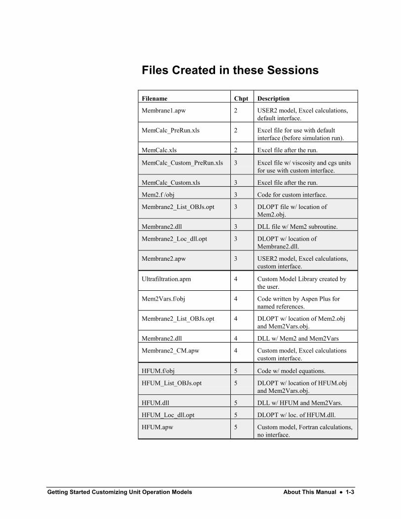
Files Created in these Sessions
Filename Chpt Description
Membrane1.apw 2 USER2 model, Excel calculations,default interface.
MemCalc_PreRun.xls 2 Excel file for use with defaultinterface (before simulation run).
MemCalc.xls 2 Excel file after the run.
MemCalc_Custom_PreRun.xls 3 Excel file w/ viscosity and cgs unitsfor use with custom interface.
MemCalc_Custom.xls 3 Excel file after the run.
Mem2.f /obj 3 Code for custom interface.
Membrane2_List_OBJs.opt 3 DLOPT file w/ location ofMem2.obj.
Membrane2.dll 3 DLL file w/ Mem2 subroutine.
Membrane2_Loc_dll.opt 3 DLOPT w/ location ofMembrane2.dll.
Membrane2.apw 3 USER2 model, Excel calculations,custom interface.
Ultrafiltration.apm 4 Custom Model Library created bythe user.
Mem2Vars.f/obj 4 Code written by Aspen Plus fornamed references.
Membrane2_List_OBJs.opt 4 DLOPT w/ location of Mem2.objand Mem2Vars.obj.
Membrane2.dll 4 DLL w/ Mem2 and Mem2Vars
Membrane2_CM.apw 4 Custom model, Excel calculationscustom interface.
HFUM.f/obj 5 Code w/ model equations.
HFUM_List_OBJs.opt 5 DLOPT w/ location of HFUM.objand Mem2Vars.obj.
HFUM.dll 5 DLL w/ HFUM and Mem2Vars.
HFUM_Loc_dll.opt 5 DLOPT w/ loc. of HFUM.dll.
HFUM.apw 5 Custom model, Fortran calculations,no interface.
1-4 •••• About This Manual Getting Started Customizing Unit Operation Models
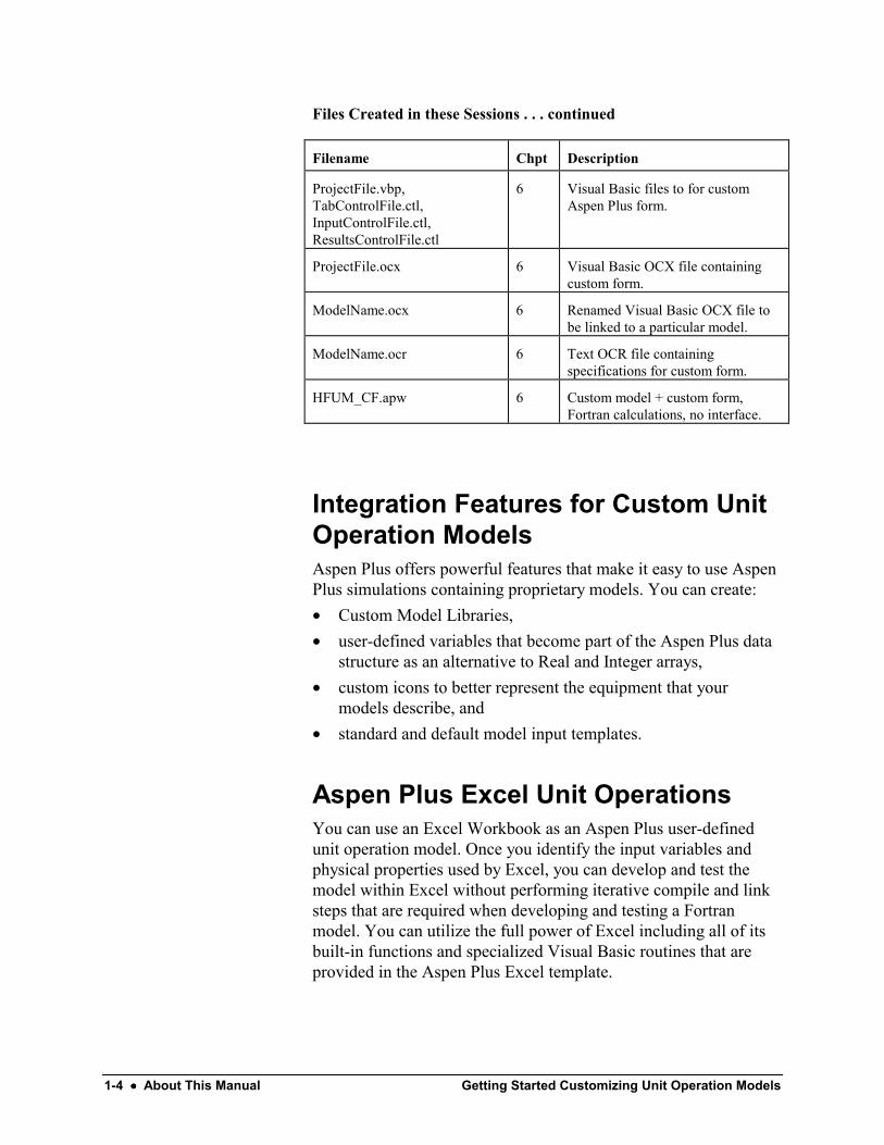
Files Created in these Sessions . . . continued
Filename Chpt Description
ProjectFile.vbp,TabControlFile.ctl,InputControlFile.ctl,ResultsControlFile.ctl
6 Visual Basic files to for customAspen Plus form.
ProjectFile.ocx 6 Visual Basic OCX file containingcustom form.
ModelName.ocx 6 Renamed Visual Basic OCX file tobe linked to a particular model.
ModelName.ocr 6 Text OCR file containingspecifications for custom form.
HFUM_CF.apw 6 Custom model + custom form,Fortran calculations, no interface.
Integration Features for Custom UnitOperation ModelsAspen Plus offers powerful features that make it easy to use AspenPlus simulations containing proprietary models. You can create:• Custom Model Libraries,• user-defined variables that become part of the Aspen Plus data
structure as an alternative to Real and Integer arrays,• custom icons to better represent the equipment that your
models describe, and• standard and default model input templates.
Aspen Plus Excel Unit OperationsYou can use an Excel Workbook as an Aspen Plus user-definedunit operation model. Once you identify the input variables andphysical properties used by Excel, you can develop and test themodel within Excel without performing iterative compile and linksteps that are required when developing and testing a Fortranmodel. You can utilize the full power of Excel including all of itsbuilt-in functions and specialized Visual Basic routines that areprovided in the Aspen Plus Excel template.

Getting Started Customizing Unit Operation Models About This Manual •••• 1-5
Aspen Plus Fortran ModelsAspen Plus provides utilities for convenient read and write accessto named user-defined variables from within the Fortran usermodel routine. This simplifies user-defined parameter mappinginto external user routines.
You can develop rich data structures for user-defined unitoperation models involving integer, real and character data. Theparameters can either be scalar or vector. Vector data can beautomatically dimensioned based on nine standard lengths such asNumber of Components or Number of Inlet Streams, or can bedynamically dimensioned based on a user-defined integer variable.
Creating GUI forms for ProprietaryModelsYou can create your own user interface forms for proprietary orcustom models using the same environment employed to createbuilt-in Aspen Plus forms. User-defined variables can be easilylinked to these forms. The forms can have a free format layout tosuit the needs of your model.
The ability to create forms, combined with the templatingcapabilities outlined in this guide, is a very powerful customizationcapability. For example, it is possible to create forms for anexisting plant unit that hides design parameters for users interestedin performing rating only calculations. These forms are easilyinserted into Aspen Plus by registering the OCX file created byVisual Basic using the Aspen Plus ApwnSetup utility.
Visual Basic template files are distributed with Aspen Plus to helpreduce the development effort.
Supporting FilesThe Aspen Plus backup, Excel, Fortran and Visual Basic filesdescribed in this book are delivered in the GUI\xmp directory ofthe Aspen Plus installation.

1-6 •••• About This Manual Getting Started Customizing Unit Operation Models
Related DocumentationA number of other documents exist to help users learn and useAspen Plus. The documentation set consists of the following:
Aspen Plus Getting Started Building and Running a Process Model
Aspen Plus Getting Started Using Equation Oriented Modeling
Aspen Plus Getting Started Modeling Processes with Solids
Aspen Plus Getting Started Modeling Processes with Electrolytes
Aspen Plus Getting Started Modeling Petroleum Processes
Aspen Engineering Suite Installation Guide for Windows
Aspen Plus User Guide
Aspen Plus User Models
Getting StartedGuides
Installation Guide
User Guides

Getting Started Customizing Unit Operation Models About This Manual •••• 1-7
Technical SupportFor additional information about AspenTech products and services,visit the AspenTech World Wide Web homepage on the Internet at:
http://www.aspentech.com/
AspenTech customers with a valid license and softwaremaintenance agreement can register to access the OnlineTechnical Support Center at:
http://support.aspentech.com/
This web support site allows you to:• Access current product documentation• Search for tech tips, solutions and frequently asked questions
(FAQs)• Search for and download application examples• Submit and track technical issues• Send suggestions• Report product defects• Review lists of known deficiencies and defects
Registered users can also subscribe to our Technical Support e-Bulletins. These e-Bulletins are used to proactively alert users toimportant technical support information such as:• Technical advisories• Product updates and Service Pack announcements
World Wide Web
Online TechnicalSupport Center
1-8 •••• About This Manual Getting Started Customizing Unit Operation Models
Customer support is also available by phone for customers with a current supportcontract for this product. The hours listed below are in local time. The numbersare:
North AmericaHours: 08:00 - 20:00 Eastern timePhone: 1-888-996-7100 (toll free)
1-281-584-435752-5-536-2809 (Mexico support center)
Fax: 1-617-949-1724 (Cambridge, MA)1-281-584-1807 (Houston, TX)
e-mail: [email protected]
ArgentinaHours: 09:00 - 17:00 Local timePhone: 54-11-4361-7220Fax: 54-11-4361-7220e-mail: [email protected]
BrazilHours: 09:00 - 17:00 Local timePhone: 55-11-5012-0321Fax: 55-11-5012-4442e-mail: [email protected]
EuropeHours: 08:30 – 18:00 Central European timePhone: 32-2-701-95-55Fax: 32-2-701-94-45e-mail: [email protected]
SingaporeHours: 09:00 - 17:30 Local timePhone: 65-395-39-00Fax: 65-395-39-50e-mail: [email protected]
TokyoHours: 09:00 - 17:30 Local timePhone: 81-3-3262-1743Fax: 81-3-3262-1744e-mail: [email protected]
Phone and e-mail
Getting Started Customizing Unit Operation Models About This Manual •••• 1-9
Toll Free Numbers – South AmericaArgentina: 0800-333-0125
Brazil: 000-814-550-4084
Venezuela: 8001-2410
Toll Free Numbers – EuropeBelgium: 0800-40-687
Denmark: 8088-3652
Finland: 0-800-1-19127
France:0805-11-0054
Germany: 800-101-0068
Ireland: 1-800-930-024
Italy: 800-905-826
Netherlands: 0800-023-2511
Norway: 800-13817
Spain: 900-951846
Sweden: 0200-895-284
Switzerland: 0800-111-470
UK: 0800-376-7903

1-10 •••• About This Manual Getting Started Customizing Unit Operation Models

Getting Started Customizing Unit Operation Models Creating an Excel Unit Operation Model •••• 2-1
Creating an Excel UnitOperation Model
Aspen Plus offers several interfaces for including custom orproprietary models in Aspen Plus simulations. Among these is theoption to use a User2 unit operation block in your Aspen Plussimulation with an Excel spreadsheet to perform the calculations.In this session you will create a User2 Excel model for anultrafiltration membrane.
First use Aspen Plus to build a process flowsheet, specify feed andproduct streams, and enter real and integer parameterscorresponding to the membrane. Then use Excel to create aspreadsheet to calculate product stream properties. Aspen Plus willwrite data to and read data from the Excel spreadsheet.
The tutorial sessions in this Getting Started Guide assume that youhave completed all of the sessions in Getting Started Building andRunning a Process Model. In particular, you must be able to:• Start Aspen Plus (using a blank simulation, template, or
existing simulation).• Place blocks and streams.• Navigate from form to form using the Data Browser menu tree.• Enter data into the required fields in the input sheets.• Run a simulation.• View the data in the results sheets.• Save a simulation.
Allow about 60 minutes for this session.

2-2 •••• Creating an Excel Unit Operation Model Getting Started Customizing Unit Operation Models
Defining the SimulationConstruct an Ultrafiltration Membrane model. Ultrafiltration is apressure-driven membrane process used to separate componentsbased on molecular size and shape. The solvent and small solutespecies pass through the membrane and are termed the permeate.Large solute species, such as proteins, are retained by themembrane and are termed the retentate.
The simulation that you will construct is shown below in Figure1.1. There is one feed stream (a water-protein feed), one unitoperation block (an ultrafiltration membrane), and two productstreams (permeate and retentate).
Figure 1.1 Ultrafiltration Membrane ModelAspen Plus will write feed stream data and real and integermembrane parameters (such as physical dimensions) to Excel.Excel will calculate product stream data such as mole flow ratesand solute concentrations using a user-specified set of equations.Aspen Plus will read the product stream data from Excel. Resultswill be displayed in the Excel file and on Aspen Plus results forms.

Getting Started Customizing Unit Operation Models Creating an Excel Unit Operation Model •••• 2-3
Setting Up the Model in Aspen PlusFor this customized simulation, Aspen Plus will handle everythingbut the calculations that correspond to the ultrafiltration processitself. First, build the process flowsheet.1 Open a new Aspen Plus simulation using the General with
Metric Units template and Flowsheet Run Type.2 From the Model Library, select the User Models tab.3 Click the arrow next to the User 2 model, select the FILTER
icon, and put a FILTER block on the process flowsheet.4 Create one input stream and two product streams.5 Name the input stream FEED by selecting the stream or its
label, right-clicking, and selecting Rename Stream.6 Name the first product stream you created RETENTAT.
Aspen Plus accepts eight letters and displays them as uppercase.
7 Name the second product stream you created PERMEATE.8 Name the block MEMBRANE.
Note: It matters which stream was created first because you willbe passing Excel (and, in the next chapter, Fortran) data to anAspen Plus array that contains product stream data. The firststream declared also comes first in the data array.
Your process flowsheet should look similar to Figure 1.1.
The next step is to enter a title, specify the components used in thesimulation, the property method, and feed stream characteristics.1 Open the Data Browser.2 Go to the Setup Specifications Global sheet and enter a title.
For example, you might call it Membrane1.We want our results to be in SI units, rather than METCBAR(the default).
3 Change the Units of measurement for Output results to SI.4 Go to the Components Specifications Selection sheet.5 In the Component ID field, type WATER and press Enter on
the keyboard.
The Component name and Formula are automatically filled inbecause Aspen Plus recognizes the ID “WATER.” Another rowopens up in the table.
Build the ProcessFlowsheet
Enter Title,Components, BaseMethod, and FeedSpecifications

2-4 •••• Creating an Excel Unit Operation Model Getting Started Customizing Unit Operation Models
6 In the next Component ID field, type PROTEIN and pressEnter on the keyboard.
Protein is not in the Aspen Plus databank, so the Componentname and Formula fields remain blank.7 In the Protein row, type LYSINE in the Component name
field, and press Enter on the keyboard.Aspen Plus recognizes the amino acid lysine and fills in theFormula field. Lysine will stand in as a protein for the purposes ofthis illustration.8 Go to the Properties Specifications Global sheet and select
the IDEAL model in the Base method field.9 Go to the Streams Feed Input Specifications sheet.10 In the Total flow section of the State variables area, change the
type of units displayed to Volume.11 In the Composition area, change the type of units displayed to
Mass-Conc.
The Solvent field is now available.12 Enter the temperature, pressure, total flow, solvent, and protein
mass concentration as indicated below.
Getting Started Customizing Unit Operation Models Creating an Excel Unit Operation Model •••• 2-5
13 Click the Flash Options tab to open the Streams FEED InputFlash Options sheet.
14 In the Valid phases field, select Liquid-Only.
Next, specify the location of the Excel file that performs membranecalculations and enter the integer and real parameters that definethe physical and calculational characteristics of the particularmembrane being used for this simulation. The integer and realparameter user array will also hold results that do not correspond tostandard Aspen Plus stream properties.1 Go to the Blocks MEMBRANE Setup Subroutines sheet.2 In the Excel file name area, enter the full path to the (future)
Excel file. For example enter:d:\Program Files\AspenTech\Excel\MemCalc.xls.
Important: Aspen Plus will accept a maximum of 64 charactersfor the Excel path. The Aspen Plus Working Folders directorymight be a more logical place for the Excel sub-directory but thepath name would be too long.
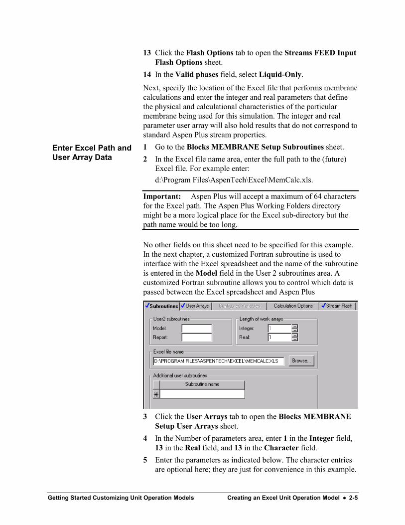
No other fields on this sheet need to be specified for this example.In the next chapter, a customized Fortran subroutine is used tointerface with the Excel spreadsheet and the name of the subroutineis entered in the Model field in the User 2 subroutines area. Acustomized Fortran subroutine allows you to control which data ispassed between the Excel spreadsheet and Aspen Plus
3 Click the User Arrays tab to open the Blocks MEMBRANESetup User Arrays sheet.
4 In the Number of parameters area, enter 1 in the Integer field,13 in the Real field, and 13 in the Character field.
5 Enter the parameters as indicated below. The character entriesare optional here; they are just for convenience in this example.
Enter Excel Path andUser Array Data

2-6 •••• Creating an Excel Unit Operation Model Getting Started Customizing Unit Operation Models
The last two real parameters are Excel-calculated results andwill appear (filled in) in the copy of the User Array table that iswritten to the Blocks MEMBRANE Results sheet after thesimulation run.
Next, make a product flash specification to cause Aspen Plus toevaluate the enthalpy and other product stream properties based onthe temperature and pressure calculated by Excel.1 Click the Stream Flash tab to open the Blocks MEMBRANE
Setup Stream Flash sheet.2 In the Stream field, select RETENTAT.3 In the Flash type field, select Temperature & pressure.4 In the Stream field, select PERMEATE.5 In the Flash type field, select Temperature & pressure.6 Save your Aspen Plus file as Membrane1.apw.
Setup a ProductStream Flash

Getting Started Customizing Unit Operation Models Creating an Excel Unit Operation Model •••• 2-7
Setting Up the Excel ModelAn Excel template is available to expedite the specificationprocess. Two templates are available – one for Excel 97 and 2000,and one for Excel 95:. . .\Engine\User\userxlTemplate.xls. . .\Engine\User\userxlTemplate95.xls
1 Place one of the templates in the folder you specified on theAspen Plus Blocks MEMBRANE Setup Subroutines sheet.
2 Open the template and save a copy as MemCalc_PreRun.xls.
Note: Later, save a copy of this file as MemCalc.xls. This secondfile will be changed by Aspen Plus and you may wish to comparethe changed version to the original MemCalc_PreRun.xls.
3 Use the tabs on the bottom of the screen to view the four Excelsheets in the template that contain data. Model calculations willbe performed on Sheet 1 (now empty).
The four data sheets and the data they will contain after thesimulation is run are listed below:• Aspen_IntParams: One integer parameter read from the
Integer User Array (entered on the Blocks MEMBRANESetup User Arrays Aspen Plus sheet).
• Aspen_RealParams: Eleven real parameters read from theReal User Array and two results (protein concentration in eachproduct stream) calculated by Excel on Sheet 1.
• Aspen_Input: The mole flow rates (in kmol/s) of eachcomponent of the feed stream and nine stream parameters.
• Aspen_Output: The mole flow rates (kmol/s) of eachcomponent of each product stream and the three product streamparameters that will be calculated by Excel. The other sixproduct stream parameters are calculated by Aspen Plus.
Copy and Examinethe Excel Template

2-8 •••• Creating an Excel Unit Operation Model Getting Started Customizing Unit Operation Models
Note: The flow rates and nine stream parameters are stored inAspen Plus in two arrays: SIN (input streams) and SOUT (outputstreams). Aspen Plus first transfers input data from SIN to Exceland then transfers output results from Excel to SOUT. All dataread from or written to SIN or SOUT must be in SI units. Moleflow data must be in kmol/s.
Next, modify the four Excel sheets to reflect the number of inputand output streams and input and output parameters in thisexample. Define variables to reference data-containing cells. Usethese variables in the model calculations performed on Sheet 1.1 Edit the Aspen_IntParams sheet as shown below. Only the
NTUBES entry in cell C2 is strictly necessary. The entries inthe first two columns are dummies; Aspen Plus will fill in thesecells when you run the simulation. Cell B2 will contain theinteger parameter from the Aspen Plus User Arrays sheet.
2 Select NTUBES and click Insert | Name | Define.3 Edit the Refers to field so that NTUBES represents the value
in cell B2.
Edit the Excel Sheets

Getting Started Customizing Unit Operation Models Creating an Excel Unit Operation Model •••• 2-9
4 Edit the Aspen_RealParams sheet as shown below. Again, theentries in the first and second column are dummies except forthe equations in cells B13 and B14. Aspen Plus will fill in thefirst two columns but will not overwrite equations.
Note: Since CP and CR haven’t been defined yet, Excel will notbe able to determine values for cells B13 and B14. To display theequations (instead of an error message) click Tools | Options |View and select the Formulas checkbox.
5 Define the boldfaced variables (one at a time) in the thirdcolumn to refer to the cells in the second column. For example,select DIAM and click Insert | Name | Define and change C2to B2 in the Refers to field.
6 Edit the Excel Aspen_Input sheet as shown below. TheFortran interface subroutine reads the actual values of the feedstream properties from the Aspen Plus SIN array and writes tocolumn B the Excel sheet. The units column is optional.
2-10 •••• Creating an Excel Unit Operation Model Getting Started Customizing Unit Operation Models
7 Define the variables in the fourth column to refer to the cells inthe second column.
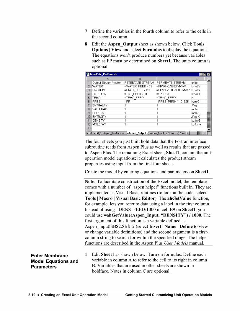
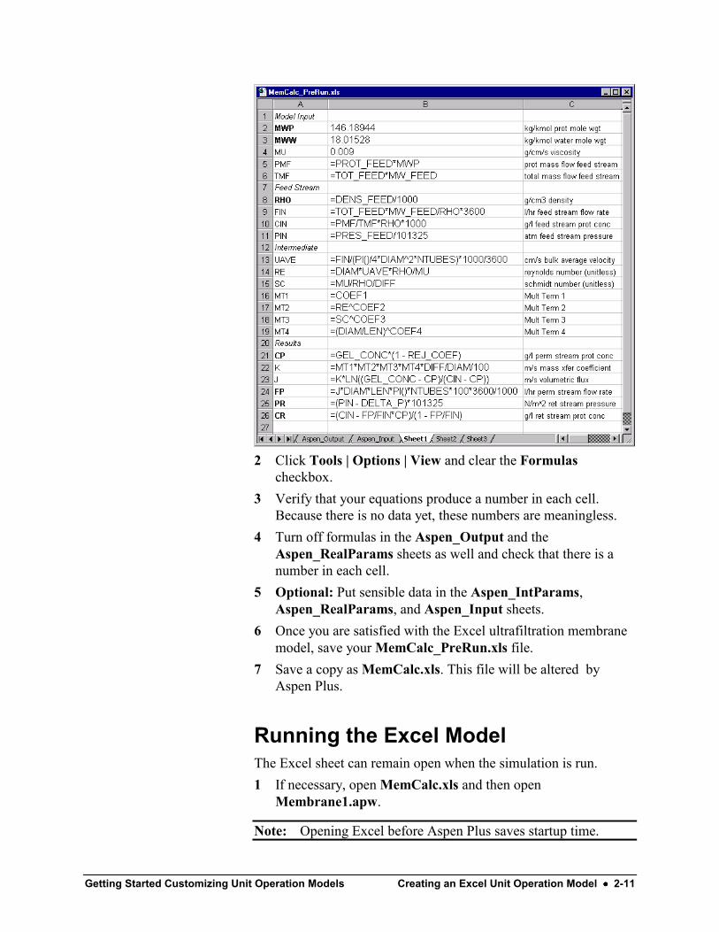
8 Edit the Aspen_Output sheet as shown below. Click Tools |Options | View and select Formulas to display the equations.The equations won’t produce numbers yet because variablessuch as FP must be determined on Sheet1. The units column isoptional.
The four sheets you just built hold data that the Fortran interfacesubroutine reads from Aspen Plus as well as results that are passedto Aspen Plus. The remaining Excel sheet, Sheet1, contain the unitoperation model equations; it calculates the product streamproperties using input from the first four sheets.
Create the model by entering equations and parameters on Sheet1.
Note: To facilitate construction of the Excel model, the templatecomes with a number of “aspen helper” functions built in. They areimplemented as Visual Basic routines (to look at the code, selectTools | Macro | Visual Basic Editor). The ahGetValue function,for example, lets you refer to data using a label in the first column.Instead of using =DENS_FEED/1000 in cell B9 on Sheet1, youcould use =ahGetValue(Aspen_Input, “DENSITY”) / 1000. Thefirst argument of this function is a variable defined asAspen_Input!$B$2:$B$12 (select Insert | Name | Define to viewor change variable definitions) and the second argument is a first-column string to search for within the specified range. The helperfunctions are described in the Aspen Plus User Models manual.
1 Edit Sheet1 as shown below. Turn on formulas. Define eachvariable in column A to refer to the cell to its right in columnB. Variables that are used in other sheets are shown inboldface. Notes in column C are optional.
Enter MembraneModel Equations andParameters
Getting Started Customizing Unit Operation Models Creating an Excel Unit Operation Model •••• 2-11
2 Click Tools | Options | View and clear the Formulascheckbox.
3 Verify that your equations produce a number in each cell.Because there is no data yet, these numbers are meaningless.
4 Turn off formulas in the Aspen_Output and theAspen_RealParams sheets as well and check that there is anumber in each cell.
5 Optional: Put sensible data in the Aspen_IntParams,Aspen_RealParams, and Aspen_Input sheets.
6 Once you are satisfied with the Excel ultrafiltration membranemodel, save your MemCalc_PreRun.xls file.
7 Save a copy as MemCalc.xls. This file will be altered byAspen Plus.
Running the Excel ModelThe Excel sheet can remain open when the simulation is run.1 If necessary, open MemCalc.xls and then open
Membrane1.apw.
Note: Opening Excel before Aspen Plus saves startup time.

2-12 •••• Creating an Excel Unit Operation Model Getting Started Customizing Unit Operation Models
2 Go to the Blocks MEMBRANE Setup Subroutines sheet andverify that the path to the Excel file is correct.
3 Press F5 to run the simulation.4 Examine the altered Excel file. Turn off formulas in each sheet
and reformat numbers as needed using the Excel Format |Cells command. The sheets are changed as follows:• Aspen_IntParams: Column A contains the row number
because no labels are specified in the default interfaceroutine. Cell B2 contains the number of tubes in themembrane model as specified on the Aspen Plus UserArrays sheet. Column C is not changed.
• Aspen_RealParams: Column A contains the row numberbecause no labels are specified in the default interfaceroutine. Column B contains the eleven real parameters fromthe Aspen Plus User Arrays sheet that describe themembrane. Cells B12 and B13 contain equations and aretherefore not directly changed by the interface routine.
• Aspen_Output: Column A already has the correct labels –the interface routine overwrites with the same labels.Columns B and C are initialized to zero except for the cellscontaining equations which are not changed. Thesubroutine CalculateData invokes the Excel calculationsand product stream results appear in cells B2:B6 andC2:C6. The interface routine reads the data in columns Band C and writes to the Aspen Plus SOUT array. AspenPlus plus performs a product stream flash to replace thezeroes in SOUT with data so that, for example, enthalpydata is available to Aspen Plus even though it is notcalculated by Excel.
• Aspen_Input: Column A already has the correct labels –the interface routine overwrites with the same labels.Column B now contains the input parameters for the feedstream. These data are read from the Aspen Plus SIN array.
• Aspen_Output_MEMBRANE: This is a new sheetcreated via a call to EndIteration which copies the contentsof Aspen_Output to this new sheet.
• Sheet 1: Using the feed stream data and real and integerparameters read from Aspen Plus arrays to the Excel sheets,the equations on Sheet1 determine concentrations and flowrates for the two output streams. The interface routine doesnot read or write directly to or from this sheet.
Getting Started Customizing Unit Operation Models Creating an Excel Unit Operation Model •••• 2-13
5 Go to the Blocks MEMBRANE Stream Results Materialsheet and the Blocks MEMBRANE Results Summary sheetverify that Aspen Plus data and Excel data are the same. Youfind that the units are different.Aspen Plus did read the correct output values from Excel but itassumed (correctly) that they were in SI units and converted thedata to METCBAR units before displaying it on the StreamResults sheet. For example, the component mole flow rates arereported in kmol/hr instead of kmol/sec.
6 Go to the Setup Specifications Global sheet, change theOutput results field to SI and run the simulation again.
7 Go back to the Stream Results form and compare the flowrates now reported in kmol/s to those listed in the Excel sheets.
8 Go to the Blocks MEMBRANE Results Summary sheet toview the real and integer parameter data read from Excel. Thelast two real parameters displayed on this Aspen Plus sheetcontain values. Aspen Plus read these values from the ExcelAspen_RealParams sheet without regard to units.
9 Save the run. This Aspen Plus file, Membrane1.apw will beused in the next chapter.
10 Exit Aspen Plus.11 Save the changed version of your Excel file, MemCalc.xls.12 Exit Excel.

2-14 •••• Creating an Excel Unit Operation Model Getting Started Customizing Unit Operation Models
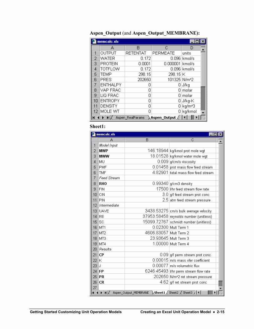
Results from the Excel ModelFor convenience, the data-filled Excel sheets and Aspen Plusresults sheets are reproduced here.Aspen_IntParams:
Aspen_RealParams:
Aspen_Input:
Getting Started Customizing Unit Operation Models Creating an Excel Unit Operation Model •••• 2-15
Aspen_Output (and Aspen_Output_MEMBRANE):
Sheet1:

2-16 •••• Creating an Excel Unit Operation Model Getting Started Customizing Unit Operation Models
Aspen Plus Blocks MEMBRANE Stream Results Materialsheet:
Aspen Plus Blocks MEMBRANE Results Summary sheet:
Getting Started Customizing Unit Operation Models Customizing the Excel/Aspen Plus Interface •••• 3-1
Customizing the Excel/AspenPlus Interface
Aspen Plus allows the user to customize the Fortran interfacesubroutine that communicates with the Excel model. You needCompaq Visual Fortran 6.0 (or a later version) to compile yourcustomized interface routine using the aspcomp command inAspen Plus Simulation Engine Window.
The interface subroutine passes feed stream data from Aspen Plusto Excel and it passes product stream data from Excel to AspenPlus. By customizing the subroutine, the user can control whichdata is passed back and forth and can manipulate the data before orafter it is processed in the Excel spreadsheet.
The Excel model in the previous chapter used Aspen Plus feedstream data in mole basis from the Aspen_Input sheet, convertedto mass basis in Sheet1, calculated the product stream flow rates,and then converted back to mole basis in Aspen_Output so thatthe data could be transferred to Aspen Plus. This was necessarybecause the Aspen Plus SIN and SOUT arrays expect flow ratedata in mole basis.
In this session you will revise the interface routine to convert theinput data to mass basis and the results data back to mole basis.The new interface routine will create custom labels for theAspen_RealParams Excel sheet. More importantly, it will obtainthe viscosity of the feed stream by calling the appropriate AspenPlus built-in subroutines. The new interface routine will then passthe viscosity to the Excel model so that the user doesn’t have toenter this parameter by hand (on Sheet1) as in the previouschapter.
Allow about 60 minutes for this session.

3-2 •••• Customizing the Excel/Aspen Plus Interface Getting Started Customizing Unit Operation Models
Revising the Excel ModelAlter the Excel file from the previous chapter so that when therevised interface routine writes the feed stream viscosity to theExcel Aspen_Input sheet, it is passed to Sheet1, converted to theappropriate units, and used in the model calculations.
Also, change Aspen_Input, Aspen_Output, and Sheet1 so thatthey use mass basis.1 Open MemCalc_PreRun.xls and save a copy as
MemCalc_Custom_PreRun.xls.2 Add row 13 to the Aspen_Input sheet as shown below.
Change the units in rows 2, 3, and 4 to indicate mass basis.
3 Define MU_ASPEN to be the viscosity that will be written tocell B13 using the Insert | Name | Define command.

Getting Started Customizing Unit Operation Models Customizing the Excel/Aspen Plus Interface •••• 3-3
4 Alter Sheet1 to use the viscosity calculated by Aspen Plus.Convert the viscosity (Aspen Plus always uses SI units) to cgsunits and change two equations in the Excel model to use massbasis. Two rows are no longer needed (PMF and TMF) andthree cells (B4, B7, and B8) require minor changes. The threenew equations are shown in boldface.
5 Alter the Excel Aspen_Output sheet to calculate componentflow rates in mass basis. The new equations are shown inboldface. Change the units in rows 2, 3, and 4 to indicate massbasis.
6 Save your new Excel file, MemCalc_Custom_PreRun.xls.

3-4 •••• Customizing the Excel/Aspen Plus Interface Getting Started Customizing Unit Operation Models
7 Save a copy of the new Excel file as MemCalc_Custom.xls sothat you retain the original version after the run. Make sure thisversion is stored in the folder specified on the Aspen PlusSubroutines sheet.
Revising the User SubroutineThe code for the default subroutine provides a template that willmake creating the customized subroutine easier. The completerevised subroutine is listed below with changes marked.1 Put a copy of \Engine\User\usrxls.f in a folder in your working
directory. For example, copy this file tod:\Program Files\AspenTech\Working Folders\AspenPlus\Membrane\Mem2.f.
2 Open Mem2.f and change the name of the subroutine toMem2.
3 Edit the file as indicated in the code listing that follows. Someof the comments from the template (usrxls.f) have beenshortened while others have been added. Numbers inparentheses following the boldface comments refer to therelevant part of the Code Description that follows the listing.

Getting Started Customizing Unit Operation Models Customizing the Excel/Aspen Plus Interface •••• 3-5
Code Listing – Subroutine MEM2
C User2 Unit Operation Model Subroutine for Excel ModelsCC You can use any subroutine name up to six characters as long asC you identify the name on the Blocks BLOCKNAME Setup SubroutinesC sheet in Aspen Plus. The argument list must not be lengthened or shortened.
SUBROUTINE MEM2 (NMATI, SIN, NINFI, SINFI, NMATO, 2 SOUT, NINFO, SINFO, IDSMI, IDSII, 3 IDSMO, IDSIO, NTOT, NSUBS, IDXSUB, 4 ITYPE, NINT, INTV, NREAL, REALV, 5 IDS, NPO, NBOPST, NIWORK, IWORK, 6 NWORK, WORK, NSIZE, ESIZE, INTSIZ, 7 LD )C IMPLICIT NONECC Declare variables used in dimensioning first, then other variables.C INTEGER NMATI, NINFI, NMATO, NINFO, NTOT, + NSUBS, NINT, NPO, NIWORK, NWORK, + NSIZE, NREAL
INTEGER IDSMI(2,NMATI), IDSII(2,NINFI), IDSMO(2,NMATO), + IDSIO(2,NINFO), IDXSUB(NSUBS), ITYPE(NSUBS), + INTV(NINT), IDS(2,3), NBOPST(6,NPO), + IWORK(NIWORK), INTSIZ(NSIZE), LD
REAL*8 SIN(NTOT,NMATI), SINFI(NINFI), SOUT(NTOT,NMATO), + SINFO(NINFO), WORK(NWORK), ESIZE(NSIZE), + REALV(NREAL)CC-------------------- Aspen Plus Common Definitions Start in Column 1. --------------C#include "dms_errout.cmn"#include "ppexec_user.cmn"#include "dms_ncomp.cmn"#include "dms_plex.cmn" REAL*8 B(1) EQUIVALENCE (B(1),IB(1))CC-------- Declare Aspen Plus utility functions that will be used. ------C INTEGER DMS_IRRCHK, DMS_IFCMNC

3-6 •••• Customizing the Excel/Aspen Plus Interface Getting Started Customizing Unit Operation Models
CC--------------------- Local Variable Declarations --------------------C INTEGER OFFSET, NUM_COLS, NUM_ROWS, RETCODE, LID, + IBLANK(2), KREAL(3), KINT(3), KINPUT(2), KOUTPUT(2), + LDATA, I,J,K, LEN, KDIAG, IDX(10), + LIDSC, NCD, C_OFF, ERRNUMBER, NUM_LINES, + SOURCE(16), HOL_STRLEN, SOR_LENGTH, SSID(2), IPROG(2), + DESC_LENGTH,KOUTSOL(3), EXCEL_NAME_LEN, + EXCEL_NAME(16), KINPSOL(3), + DESCRIPTION(128) !Moved LABELS and ROWNAMES declarations. (1)
Integer LABELS(2,10), ROWNAMES(2,NCOMP_NCC+10) !Ten labels instead of nine. (1)Integer REALROWS(2,NTOT+1) !Hollerith Realparam row ID's. (2)Integer LMW, NCP !Conversion and Viscosity. (3)Real*8 FLOW, XMW, X(10) !Calc component mass flow. (4)Character*8 RealLabels(13) !Realparam row ID's. (5)
REAL*8 INSTREAM(NTOT*NMATI),OUTSTREAM(NTOT*NMATO)CC--------------------------- Data Section -----------------------------C
DATA KINPUT /4HINPU, 4HT / DATA KOUTPUT /4HOUTP, 4HUT / DATA KREAL /4HREAL, 4HPARA, 4HMS / DATA KINT /4HINTP, 4HARAM, 4HS / DATA KINPSOL /4HINP_, 4H , 4H / DATA KOUTSOL /4HOUT_, 4H , 4H / DATA IPROG /4HUSRX, 4HLS / DATA IBLANK /4HIMIS, 4HS /
DATA LABELS /4HTOTF, 4HLOW , + 4HTEMP, 4H , + 4HPRES, 4H , + 4HENTH, 4HALPY, + 4HVAP , 4HFRAC, + 4HLIQ , 4HFRAC, + 4HENTR, 4HOPY , + 4HDENS, 4HITY , + 4HMOLE, 4H WT , + 4HMUMX, 4H / !MUMX is viscosity label. (6)

Getting Started Customizing Unit Operation Models Customizing the Excel/Aspen Plus Interface •••• 3-7
DATA RealLabels / 'x ', !Labels for Realparam table (each total eight chars). (7) + 'L ', + 'Dab ', + 'Cg ', + 'R ', + 'C1 ', + 'C2 ', + 'C3 ', + 'C4 ', + 'Pperm ', + 'DeltaP ', + 'Cp ', + 'Cr ' /
C----------------------------------------------------------------------C- Establish Excel link and call StartIteration Workbook Hook FunctionC CALL USRUTL_GETEXCEL(EXCEL_NAME, EXCEL_NAME_LEN) CALL StartIteration(RETCODE, EXCEL_NAME,64, IDS(1,1), 8)
IF(RETCODE .NE. 0) GOTO 1000
C--------------- Build Aspen_Input Data Table -------------------------CC First get name of each of the NCOMP_NCC components forC first NCOMP_NCC rows in column 1 of the table. Names are inC two four letter blocks. Component names in column 1 labelC component flow rates in column 2.
OFFSET = DMS_IFCMNC('IDSCC') DO J=1, NCOMP_NCC I = OFFSET + 2*(J-1) + 1 ROWNAMES(1,J) = IB(I) ROWNAMES(2,J) = IB(I+1) END DO
C After the component names, list the nine standard stream properties plusC any extras (in this case, there is one extra).
DO K=1, 10 !9����10 (8) J = K + NCOMP_NCC ROWNAMES(1,J) = LABELS(1,K)
ROWNAMES(2,J) = LABELS(2,K) END DO NUM_ROWS = NCOMP_NCC + 10 !9����10 (8)

3-8 •••• Customizing the Excel/Aspen Plus Interface Getting Started Customizing Unit Operation Models
C Now fill in column 2 (using the INSTREAM array) with Aspen Plus feedC stream data ( from the SIN array). Convert to mass basis using molecular weights.C Make a column for each feed stream. Also have Aspen Plus calculate viscosity ofC feed stream.
LMW = DMS_IFCMNC('MW') !Will need molecular weights of individual!components to do flow rate conversions. (9)
NUM_COLS = NMATI
DO J=1, NUM_COLS
OFFSET = (J-1)*(NCOMP_NCC+10)
DO I=1, NUM_ROWS
IF (I .EQ. NUM_ROWS) THEN !To do last row (10) Call SHS_CPACK(SIN(1,J), NCP, IDX, X, FLOW) !"pack" data KDIAG = 4 !then get K = NCOMP_NCC !viscosity. (11) Call PPMON_VISCL(SIN(K+2,J), SIN(K+3,J), X, NCP,
+ IDX, NBOPST, KDIAG, + INSTREAM(OFFSET+I), RETCODE)
ELSE XMW = 1 !Only convert flow rates.
IF(I .LE. NCOMP_NCC) XMW = B(LMW + I) !If doing flow rates,
!make XMW molecular wgt. (12) INSTREAM(OFFSET + I) = SIN(I,J)*XMW !Convert and fill INSTREAM.END IF
IF (I .EQ. NCOMP_NCC+1) !Convert total mole flow to total mass !flow using molec wgt of stream. (13)
+ INSTREAM(OFFSET+I) = INSTREAM(OFFSET+I)*SIN(I+8,J)
END DO
END DO
C--------------- Send Aspen_Input table to Excel. ----------------------
LDATA = 8*NUM_ROWS*NUM_COLS CALL WRITETABLE(RETCODE , KINPUT, 8 , NUM_ROWS, + ROWNAMES, 8 , NUM_COLS, IDSMI , + 8 , 2 , INSTREAM, LDATA ) IF (RETCODE .NE. 0) GO TO 1000
C------------ Send Aspen_IntParams table to Excel. ---------------------
LDATA = 8*NINT CALL WRITETABLE(RETCODE, KINT, 12 , NINT , + IBLANK , 0 , 1 , IBLANK, + 0 , 1 , INTV,LDATA ) IF (RETCODE .NE. 0) GO TO 1000
C-------------- Send Aspen_RealParams table to Excel. -------------------
Getting Started Customizing Unit Operation Models Customizing the Excel/Aspen Plus Interface •••• 3-9
DO I = 1, 13 !Make the 13 labels into Holleriths. (14)CALL USRUTL_CHARTOH(RealLabels(I), RealRows(1,I), 8)
END DO
LDATA = 8*NREAL CALL WRITETABLE(RETCODE, KREAL, 12 , NREAL , + RealRows, 8 , 1 , IBLANK, !Send Labels, Length to Excel. + 0 , 2 , REALV,LDATA ) IF (RETCODE .NE. 0) GO TO 1000
C-------- Initialize the Aspen_Output Excel table. ---------------------
NUM_ROWS = NCOMP_NCC + 9 !No viscosity for output streams. (15)DO J=1, NMATO
OFFSET = (J-1)*(NCOMP_NCC+9) DO I=1, NUM_ROWS
OUTSTREAM(OFFSET+I) = 0.D0 END DO END DO
NUM_COLS = NMATO LDATA = 8*NUM_ROWS*NUM_COLS CALL WRITETABLE(RETCODE , KOUTPUT, 8 , NUM_ROWS, + ROWNAMES, 8 , NUM_COLS , IDSMO , + 8 , 2 , OUTSTREAM, LDATA ) IF (RETCODE .NE. 0) GO TO 1000
C------------ Invoke Excel Workbook Calculations ----------------------
CALL CalculateData(RETCODE) IF (RETCODE .NE. 0) GOTO 1000
C---------- Read Excel values into Aspen Plus Arrays ----------
C----- Read back integer parameter table in case it has results.
LDATA = 8*NINT CALL READTABLE(RETCODE, KINT, 12 , NINT , + 1 , 1 , INTV, LDATA) IF (RETCODE .NE. 0) GOTO 1000
C -- Read back real parameter table in case it has results.
LDATA = 8*NREAL CALL READTABLE(RETCODE, KREAL, 12 , NREAL, + 1 , 2 , REALV, LDATA) IF (RETCODE .NE. 0) GOTO 1000

3-10 •••• Customizing the Excel/Aspen Plus Interface Getting Started Customizing Unit Operation Models
CC Read product stream data from Excel Aspen_Output sheet to OUTSTREAM.C Only have component flow rates, total flow rate, temperature and pressure.C First column of data (the retentate stream data) comes first in the 1 dimensionalC OUTSTREAM array.C NUM_ROWS = NCOMP_NCC + 3 ! 9����3; Two flow rates + tot flow, temp, pres. (16) NUM_COLS = NMATO LDATA = 8*NUM_ROWS*NUM_COLS CALL READTABLE(RETCODE , KOUTPUT, 8 , NUM_ROWS, + NUM_COLS, 2 , OUTSTREAM, LDATA ) IF (RETCODE .NE. 0) GOTO 1000CC Put results from two product streams (OUTSTREAM array) in Aspen Plus product streamC array (2 dimensional SOUT). The second dimension of SOUT is the number of streams;C The first stream placed by the user on the Aspen Plus process flowsheet comes first in SOUT.C Retentate stream was placed first and it must also be listed first in the Excel Aspen_Output sheet.C SOUT expects flow rate data in mole basis so convert back to mole basis using molecularC weights. This time get total mole flow by just adding up component mole flows.C
DO J = 1, NMATO
FLOW = 0 ! Holds the total mole flow.OFFSET = (J-1)*NUM_ROWS
DO I = 1, NUM_ROWS
IF(I .LE. NCOMP_NCC) THEN !Convert flow rates to mole SOUT(I, J) = OUTSTREAM(OFFSET+I)/B(LMW+I) !basis and fill Aspen Plus array. (17) FLOW = FLOW + SOUT(I,J) !Store total. (17) ELSE IF(I .EQ. NCOMP_NCC+1) THEN SOUT(I,J) = FLOW !Total flow to SOUT (3rd row). (17) ELSE !For other rows, just fill array. SOUT(I,J) = OUTSTREAM(OFFSET + I) END IF
END DO
END DOC----------------------------------------------------------------------CC--------------- End of Current Iteration ------------- !No more changes.
CALL EndIteration(RETCODE) RETURN

Getting Started Customizing Unit Operation Models Customizing the Excel/Aspen Plus Interface •••• 3-11
C------------------------ Error Handling Section ---------------------- 1000 CONTINUECC ALL ERRORS COME HERE TO REPORT ERRORSCC Call GetLastTableDataErr()CC HOL_STRLEN SETS THE PADDING FOR ERROR HANDLING STRING RETURNEDC FROM THE EXCEL INTERFACE.C HOL_STRLEN = 64 DESC_LENGTH= 512 SOR_LENGTH = 64 CALL GetLastTableDataErr(RETCODE, ERRNUMBER, DESCRIPTION, + DESC_LENGTH, HOL_STRLEN, SOURCE, + SOR_LENGTH)C REGISTER SEVERE SIMULATION ERROR FROM USER2 WITH ENGINE USER_ICONVG = -3 IF (DMS_IRRCHK(IPROG, 1, 4, 4, USER_IUMISS, + 0, 0, 2) .NE. 0) THENC DETERMINE NUMBER OF LINES OF LENGTH HOL_STRLEN TO PRINTC MAX IS 10 SO WE CAN USSE 8 FOR DESCRIPTION OF ERROR NUM_LINES = ( (DESC_LENGTH+HOL_STRLEN-1) /HOL_STRLEN) IF (NUM_LINES .GT. 8 ) NUM_LINES = 8C MOVE STRINGS TO ERROUT_IEROUT ARRAY OF STRINGS. WILL BE PRINTEDC TO HISTRY FILE BY ERRPRT(). FIRST WRITE "MS Excel" THEN SOURCEC STRING RETURNED BY API AS ERROR HEADING. WRITE(ERROUT_IEROUT(1), 10) WRITE(ERROUT_IEROUT(2), 11)(SOURCE(I), I=1,(SOR_LENGTH+3)/4)C WRITE ERROR MESSAGE RETURNED FROM EXCEL API TO THE HISTORY FILE DO 111 J=1,NUM_LINES C_OFF = (J-1) * HOL_STRLEN/4 WRITE(ERROUT_IEROUT(J+2), 11) + ( DESCRIPTION(I+C_OFF), I=1,(HOL_STRLEN+3)/4 ) 111 CONTINUEC PRINT ERROR MESSAGES TO HISTORY FILE USING THE FIRST NUMLINES+2C LINES OF THE ERROUT_IEROUT ARRAY OF STRINGS. CALL DMS_ERRPRT(NUM_LINES+2) ENDIFC END ERROR REPORTING TO HISTORY FILE 2000 CONTINUEC Call EndIteration()C EndIteration IS CALLED EVEN WHEN A SEVERE ERROR OCCURS ABOVE. CALL EndIteration(RETCODE)999 CONTINUEC FORMAT STATEMENTS10 FORMAT(' MS EXCEL Interface Reports:')11 FORMAT(' ',16A4)
END

3-12 •••• Customizing the Excel/Aspen Plus Interface Getting Started Customizing Unit Operation Models
Code Description – Subroutine MEM21 The MUMX (viscosity) addition to the list of stream properties
means that there will be 10 properties read from Aspen Plusinstead of the usual 9 so LABELS and ROWNAMES must beredimensioned.
2 We want to add labels (stored in REALROWS) to theAspen_RealParams table.
3 LMW will hold the “offset” to the location of the molecularweight data for each component. NCP will hold the actualnumber of components present in the stream.
4 FLOW will hold the total mole flow for the output streams.XMW will hold the molecular weight data for a givencomponent. X will contain the mole fraction of eachcomponent actually present in the stream and is sent to thePhysical Property Monitor subroutine PPMON_VISCL whichcalculates the viscosity of the stream.
5 RealLabels is a character array for the labels of theAspen_RealParams Excel sheet that will be converted toHollerith format.
6 MUMX is stored in Hollerith format and will be written to theAspen_Input and Aspen_Output Excel sheets along with thestandard nine stream property labels.
7 Labels for the Aspen_RealParam table are entered explicitly asa character array.
8 There are now 10 rows in the Aspen_Input and Aspen_Outputtables in addition to the NCOMP_NCC = 2 rows thatcorrespond to the component flow rates so DO loops have to belengthened.
9 DMS_IFCMNC is an integer function that determines thelocation of the data such as molecular weight and criticaltemperature that corresponds to each component. The usersubroutine includes the following statements:#include "dms_plex.cmn" REAL*8 B(1) EQUIVALENCE (B(1),IB(1))
These statements allow the subroutine to access componentdata. The character strings to feed to the DMS_IFCMNfunction are listed in the Universal Constant Names andDefinitions table in Chapter 6 of the User Models manual. Themolecular weight of the first component will be found atB(LMW + 1) where LMW is the offset returned by thefunction.
Getting Started Customizing Unit Operation Models Customizing the Excel/Aspen Plus Interface •••• 3-13
10 The subroutine SHS_CPACK “packs” the stream array bydetermining which components are actually present (have anon-zero flow rate) and putting their mole fractions in the Xarray. The PPMON_VISCL subroutine needs a packed streamarray when it calculates stream viscosity.
11 The subroutine PPMON_VISCL returns the viscosity of thestream. In the subroutine in this example, the viscosity isplaced in the INSTREAM array.
12 The “B” array is used to get the molecular weight which is usedto convert component flow rates. The integer variableNCOMP_NCC is equal to the number of conventionalcomponents (in this case 2) declared in the ComponentsSpecifications Selection sheet and is passed through thecommon DMS_NCOMP also included in this subroutine.
13 The total mole flow is the third (NCOMP_NCC + 1) entry inthe Aspen Plus stream input array called SIN. The first two(NCOMP_NCC) are the component mole flows. The next eightstream properties are temperature, pressure, enthalpy, vaporfraction, liquid fraction, entropy, density, and molecularweight. These are listed in Appendix C of the User Modelsmanual and these are the data that appear in the Aspen_Inputand Aspen_Output Excel sheets.
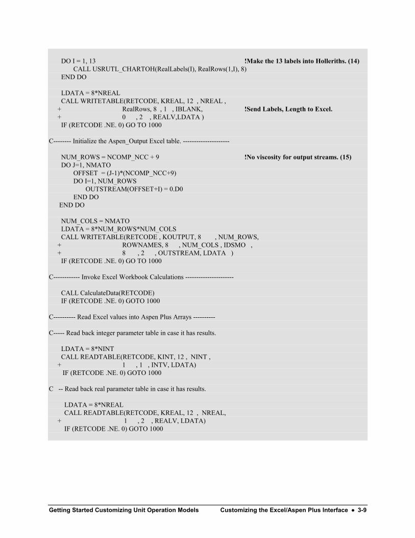
14 The subroutine USRUTS_CHARTOH converts the explicitlyentered character labels into Hollerith format so that they maybe sent to the WRITETABLE subroutine.
15 Only the viscosity of the feed stream is calculated so the outputtable still has the usual (NCOMP_NCC + 9) rows.
16 Since the Excel model only calculates flow rates, temperature,and pressure, there is no point sending it a bunch of zeroes forthe other properties. The properties that Excel does calculateare placed in OUTSTREAM when READTABLE is called.
17 The array SOUT contains the same NCOMP_NCC componentmole flows, total flow, and 8 other properties as SIN (see item13 above). When the SOUT array is filled with theOUTSTREAM values, these data will be available in AspenPlus results sheets. The SIN and SOUT arrays containcomponent and total flow rates in mole basis (kmol/s) and eightother properties in standard SI units.

3-14 •••• Customizing the Excel/Aspen Plus Interface Getting Started Customizing Unit Operation Models
Compiling and Linking theSubroutineThe aspcomp command delivered in the Simulation Engine DOSprompt window will create the .OBJ file and ensure consistentcompiler options. Two “DLOPT” (dynamic linking option) filescontrol the linking process: one creates a DLL from specified .OBJfiles and another tells Aspen Plus where to find the DLL beingused for a particular run.
1 Save your customized Fortran file as Mem2.f.2 Launch the Aspen Plus Simulation Engine Window. (From the
Start menu click Programs | AspenTech | AspenEngineering Suite | Aspen Plus | Aspen Plus SimulationEngine.)
A DOS window appears with the working directory as the defaultdirectory.
3 Use the DOS cd command to set the default directory to thelocation of Mem2.f. For example, type cd membrane if yourFortran file is in a subfolder called membrane in your workingdirectory.
4 Type aspcomp Mem2 to compile the subroutine.
An object file (Mem2.obj) is created in the same directory asMem2.f.
Compile the ExcelInterface Subroutine

Getting Started Customizing Unit Operation Models Customizing the Excel/Aspen Plus Interface •••• 3-15
Keep the DOS window available for the linking step and use a texteditor to create a DLOPT file to control the creation of a sharedlibrary (also known as a dynamic linking library).1 Use a text editor such as Notepad to create a text file called
Membrane2_List_OBJs.opt.2 Type the full path to Mem2.obj in the top line of the text file.
For example: D:\Program Files\ . . .\membrane\Mem2.obj.
3 Save the file and exit the text editor.4 In the DOS window of the Aspen Plus Simulation Engine, type
asplink [dlopt membrane2_list_objs.opt] membrane2.A file called membrane2.dll is created. This is a Fortran sharedlibrary. Using a shared library avoids the need for a linking stepwhen Aspen Plus runs. Once you have the shared library, it can beused with Aspen Plus even if you don’t have a Fortran compileravailable.
Note: If you simply type asplink membrane2 Aspen Plus willcreate membrane2.dll using all the object files in the defaultdirectory.
5 Create another DLOPT text file calledMembrane2_Loc_DLL.opt.
6 In the top line of this file type the full path to membrane2.dll.
7 Save the text file and exit the text editor.8 Put a copy of the Membrane2_Loc_DLL.opt in your Aspen
Plus Working Directory. At run time, you will tell Aspen Plusthe name of this file so that the shared library will be available.
Create a SharedLibrary

3-16 •••• Customizing the Excel/Aspen Plus Interface Getting Started Customizing Unit Operation Models
Running the SimulationNow that you have your revised Excel file and have created ashared library containing your customized Fortran subroutine, youcan run the simulation using membrane1.apw from the previouschapter.1 Open membrane1.apw.2 Select Run | Reinitialize (or press Shift-F5) and click OK
twice to clear data from the previous run.
Note: If you have both the GUI and the Simulation EngineWindow open at the same time, an asplink command, will failunless you reinitialize the open run.
3 Go to the Setup Specifications Global sheet, change the titleto membrane2, and make sure SI units are selected for theoutput.
4 Go to the Blocks MEMBRANE Setup Subroutines sheet andtype MEM2 in the Model field in the User2 subroutines areaso that Aspen Plus knows what your new subroutine is called.
5 On the Subroutines sheet, change the name of the Excel file toMemCalc_Custom.xls.
6 From the Aspen Plus menu, select Run | Settings.

Getting Started Customizing Unit Operation Models Customizing the Excel/Aspen Plus Interface •••• 3-17
The Run Settings dialog box appears.7 In the Linker options field in the Miscellaneous files area type
membrane2_loc_dll.opt so that Aspen Plus knows the nameof the file containing the location of the library that containsyour customized subroutine. This DLOPT file must be in yourAspen Plus Working Folder.
8 Click OK.9 Run the simulation.10 Compare your Aspen Plus and Excel Results to those displayed
below.11 Save the run as membrane2.apw and exit Aspen Plus.
Warning: The Linker options entered above are not saved in the.apw file and must be re-entered when you open the saved file.

3-18 •••• Customizing the Excel/Aspen Plus Interface Getting Started Customizing Unit Operation Models
Results from the Custom Excel ModelFor convenience Excel and Aspen Plus sheets are shown here.
The Excel Aspen_Input sheet appears below. It now containsviscosity data as calculated by Aspen Plus. The original label“Aspen Viscosity” was overwritten with the new label “MUMX”specified in the interface routine.
The Excel Aspen_RealParams sheet appears below. It nowcontains labels in column A specified in the interface routine. Thevalue of Cr in cell B14 is slightly different from that in theprevious chapter because the viscosity used in this example is moreaccurate:

Getting Started Customizing Unit Operation Models Customizing the Excel/Aspen Plus Interface •••• 3-19
The Excel Aspen_Output sheet appears below. It contains flowrates in mass basis.
The Aspen Plus Blocks MEMBRANE Stream Results Materialsheet:
3-20 •••• Customizing the Excel/Aspen Plus Interface Getting Started Customizing Unit Operation Models
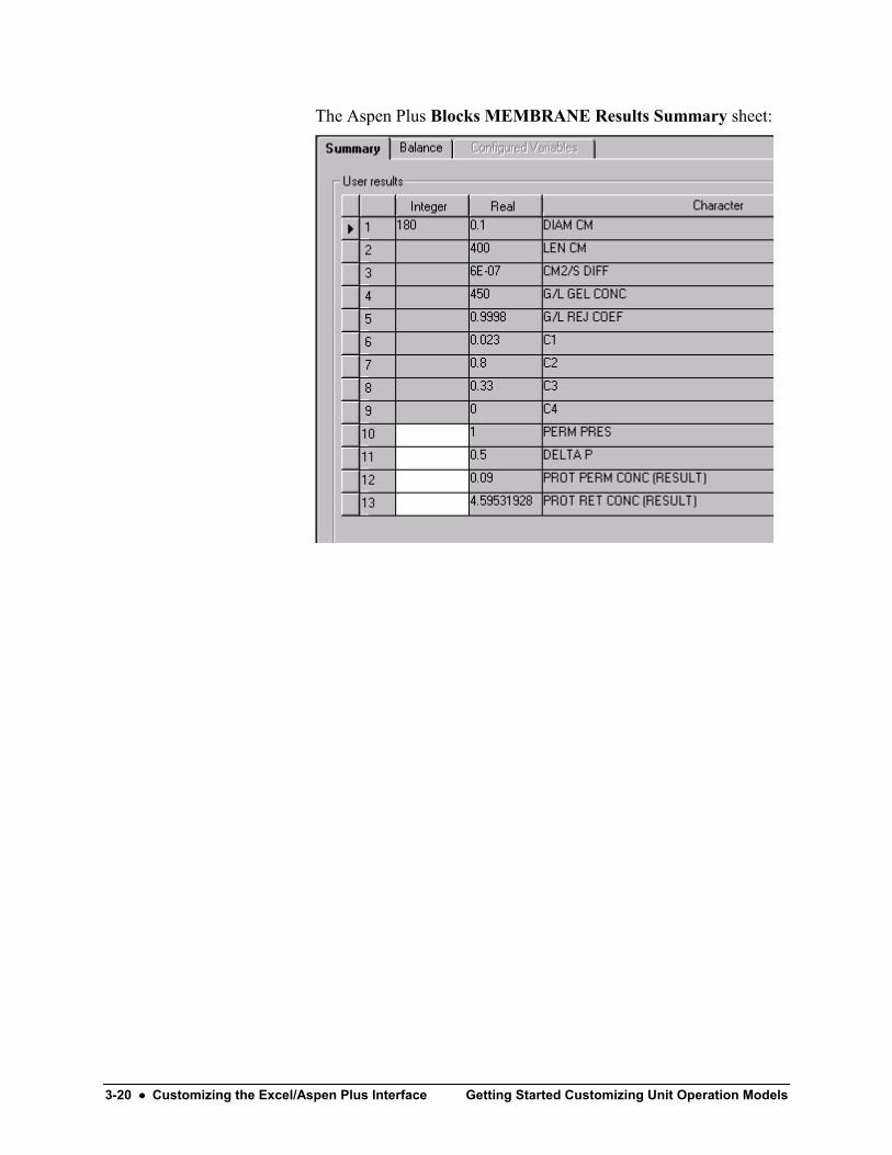
The Aspen Plus Blocks MEMBRANE Results Summary sheet:
Getting Started Customizing Unit Operation Models Customizing the Aspen Plus Model Library •••• 4-1
Customizing the Aspen PlusModel Library
Your customized Excel model can have its own unit operationmodel stored in an Aspen Plus Library file (.apm extension) anddisplayed in the Model Library palette. In the previous chapter youentered a set of real and integer parameters for the physicalcharacteristics and calculational coefficients of the model using theAspen Plus User Arrays data sheet. With a customized unitoperation model, you can enter these parameters once and they willbe automatically included whenever the customized block is placedon the Process Flowsheet.
In addition, the name of the user Fortran subroutine and Excel filecan be associated with the customized model. The icon itself canbe custom drawn.
Finally, a Configured Variables sheet is available in which the setof real and integer parameters are associated with character stringsand identified as input or output. This data can be accessed in theuser Fortran subroutine by referring to the variable names, therebysimplifying the code.
In this session, create a new Aspen Plus Library,Ultrafiltration.apm, containing a customized model for theultrafiltration membrane. Use the same model parameters as in theprevious chapter to specify the membrane characteristics. Create acustom icon for your model. Then replace the User 2 block inmembrane2.apw with your custom block and run the simulationagain.
Allow about 30 minutes for this session.
4-2 •••• Customizing the Aspen Plus Model Library Getting Started Customizing Unit Operation Models
Creating a Model LibraryA model library has three levels: the library itself consists of a setof categories each identified by a tab in the Model Library palette.Each category consists of a set of models. Each model isrepresented by an icon (multiple icons may be created and used forstrictly aesthetic reasons) and has default parameters associatedwith it. The present hollow fiber ultrafiltration membrane has 180tubes but another might have only 90. They could be represented asseparate models.1 Create a sub-folder in your Aspen Plus Working Folder called,
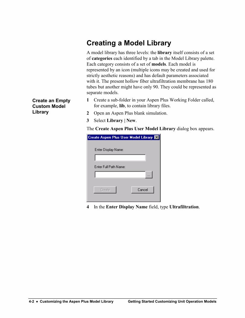
for example, lib, to contain library files.2 Open an Aspen Plus blank simulation.3 Select Library | New.
The Create Aspen Plus User Model Library dialog box appears.
4 In the Enter Display Name field, type Ultrafiltration.
Create an EmptyCustom ModelLibrary

Getting Started Customizing Unit Operation Models Customizing the Aspen Plus Model Library •••• 4-3
5 Click (it’s a Browse button) and navigate to the directorywhere you wish to store library files.
The New User Model Library dialog box appears.
6 Click Save.
The previous dialog box reappears.7 Click Create.
You have created an empty library. It contains no categories and nomodels. The next step is to create a template that contains defaultparameters for your customized model.1 From the Model Library, place a User Models User 2
FILTER block on the process flowsheet. It gets the default IDB1.
2 Open the Data Browser and go to the Blocks B1 SetupSubroutines sheet.
3 In the Model field, type the name of the Fortran subroutine thatwill be used with the customized block. For this example, typeMem2.
4 In the Excel file name area, type the path the Excel file thatcontains the equations for the model. For example, d:\ProgramFiles\ApsenTech\Excel\MemCalc_Custom.xls.
Create a Template forYour Custom Model

4-4 •••• Customizing the Aspen Plus Model Library Getting Started Customizing Unit Operation Models
5 Click the User Arrays tab and enter the same real and integerparameters as in the previous chapter including two empty realparameters for results data.
Now your template is prepared and you are ready to create thecustomized model.1 Go back to the Process Flowsheet.2 Select your template block, right click, and select Add to
Model Library.
Note: If you start Aspen Plus in the future and find the Add toModel Library option unavailable, select Library | References . .and select your library (Ultrafiltration). Then select Library |Ultrafiltration | Writable so that you can edit it or add a model toit. Select Library | Save Default to make sure the selected libraryis available whenever you start Aspen Plus.
Create the CustomModel from theTemplate
Getting Started Customizing Unit Operation Models Customizing the Aspen Plus Model Library •••• 4-5
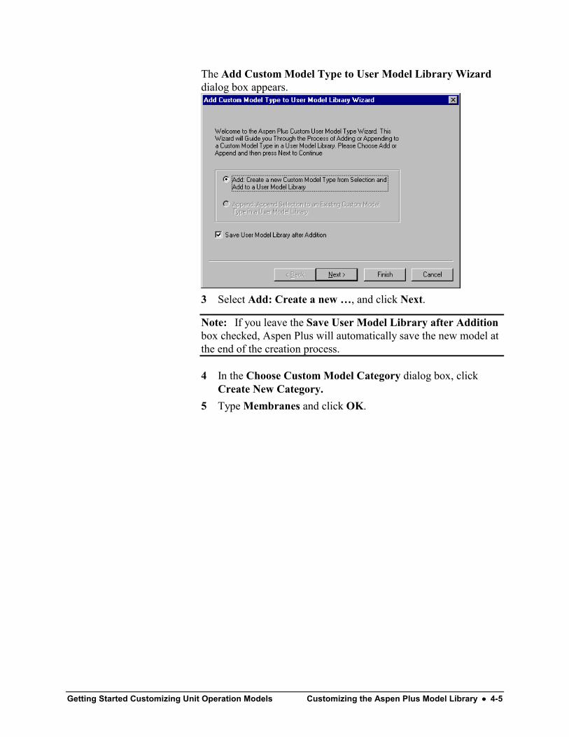
The Add Custom Model Type to User Model Library Wizarddialog box appears.
3 Select Add: Create a new …, and click Next.
Note: If you leave the Save User Model Library after Additionbox checked, Aspen Plus will automatically save the new model atthe end of the creation process.
4 In the Choose Custom Model Category dialog box, clickCreate New Category.
5 Type Membranes and click OK.

4-6 •••• Customizing the Aspen Plus Model Library Getting Started Customizing Unit Operation Models
The Choose Custom Model Category dialog box reappears.
6 Select Membranes and click Next.
The Choose Single Block or Multi Record Custom Model Typedialog box appears.
7 Select Single Block Custom Model and click Next.

Getting Started Customizing Unit Operation Models Customizing the Aspen Plus Model Library •••• 4-7
The Choose Custom Model Type Creation Options dialog boxappears with the block ID (B1) entered automatically.
8 Replace B1 with HollowF.9 Choose any icon option. Later, you will delete the icon and
create a custom icon.10 Make sure the Copy/create model template checkbox is
selected. Aspen Plus will copy the data you entered on theSubroutines sheet and on the User Arrays sheet into the newmodel.
11 Make sure the Copy/create user model configurationcheckbox is selected. Aspen Plus will make the ConfiguredVariables sheet available to the new model so that you canassociate variable names with your real and integer parameters.
12 Click Finish. Aspen Plus automatically saves the new library.(Select Library | Ultrafiltration; the Save option should beshaded.)
A tab for the Membranes category of the Ultrafiltration librarynow appears alongside the tabs of the Built-in library.13 In the Model Library click the Membranes tab.

4-8 •••• Customizing the Aspen Plus Model Library Getting Started Customizing Unit Operation Models
The model you created is visible.
14 Delete the block on the Process Flowsheet that you used as atemplate.
15 From the Model Library, drag a HollowF unit operation modelonto the Process Flowsheet.
16 Open the Data Browser and go to the Blocks B1 Setup formand check that the default data appears correctly on theSubroutines sheet and on the User Arrays sheet.
17 Exit Aspen Plus. There is no need to save an apw file since thelibrary is already saved as Ultrafiltration.apm.
Now, whenever you start Aspen Plus and select Library |References and click the Ultrafiltration checkbox, you will haveaccess to the HollowF unit operation model with default usersubroutine name, Excel file path, and real and integer parameters.
Note: Any Aspen Plus model from the Model Library can bemoved into the new library by dragging the icon into the ModelLibrary Editor (select Library | Ultrafiltration | Edit to open theEditor). The Add Custom Model Type to User Model LibraryWizard appears automatically.
Editing the Custom ModelWhen you use a model from a custom library, you can overwritethe default entries to the Blocks | BLOCKNAME | Setup |Subroutines and User Array sheets. For example, in the nextchapter, you will place a HollowF block, delete the path to theExcel file and use a revised Fortran subroutine to perform themodel calculations. This change only affects the block to which itis applied. The defaults for the HollowF model remain intact.
The HollowF model can be edited, however, in the followingways: you can delete it, rename it, redraw the icon, and add namedvariables that refer to the real and integer parameters on the UserArrays sheet. These changes are stored in the library when youselect Library | LIBNAME | Save.
Getting Started Customizing Unit Operation Models Customizing the Aspen Plus Model Library •••• 4-9
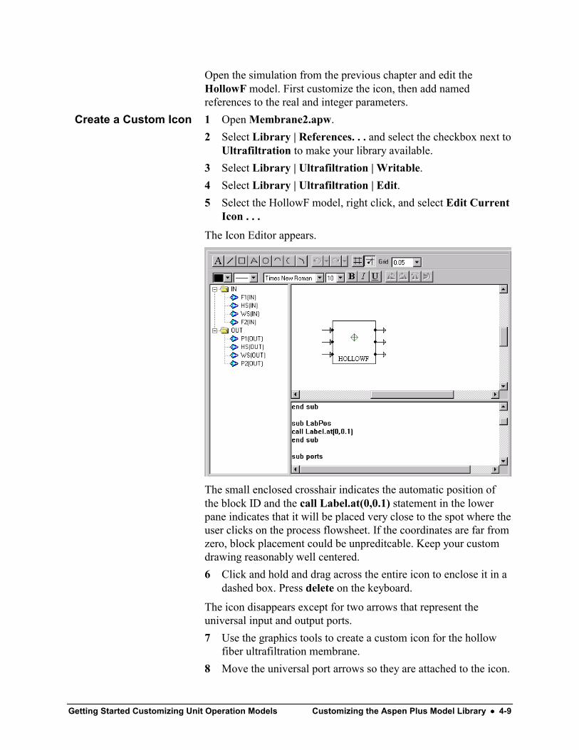
Open the simulation from the previous chapter and edit theHollowF model. First customize the icon, then add namedreferences to the real and integer parameters.1 Open Membrane2.apw.2 Select Library | References. . . and select the checkbox next to
Ultrafiltration to make your library available.3 Select Library | Ultrafiltration | Writable.4 Select Library | Ultrafiltration | Edit.5 Select the HollowF model, right click, and select Edit Current
Icon . . .The Icon Editor appears.
The small enclosed crosshair indicates the automatic position ofthe block ID and the call Label.at(0,0.1) statement in the lowerpane indicates that it will be placed very close to the spot where theuser clicks on the process flowsheet. If the coordinates are far fromzero, block placement could be unpreditcable. Keep your customdrawing reasonably well centered.6 Click and hold and drag across the entire icon to enclose it in a
dashed box. Press delete on the keyboard.
The icon disappears except for two arrows that represent theuniversal input and output ports.7 Use the graphics tools to create a custom icon for the hollow
fiber ultrafiltration membrane.8 Move the universal port arrows so they are attached to the icon.
Create a Custom Icon

4-10 •••• Customizing the Aspen Plus Model Library Getting Started Customizing Unit Operation Models
9 Drag an F1(IN) port from the left-hand pane and place itdirectly over the universal input arrow.
10 Drag a P1(OUT) port from the left-hand pane and place itdirectly over the universal output arrow.
11 Select Icon | Update icon to update the code in the lower pane.
12 Exit the Icon Editor by closing the window.13 Click Yes when prompted to save the new icon.14 Select Library | Ultrafiltration | Save to save the changes to
the library.15 Exit the Model Library Editor by closing the window.
Note: Existing AutoCAD DXF files can also be imported into theIcon Editor. When the Icon Editor is active, a main Icon menubecomes available on the menu bar for the main window. SelectImport DXF from the Icon menu.
Getting Started Customizing Unit Operation Models Customizing the Aspen Plus Model Library •••• 4-11
Next, add named references to the real and integer parameterarrays. These names will be used in the Fortran code in the nextchapter. For the simulation in this chapter, the two parametersdesignated as output data will appear in a new results sheet.Otherwise this run will be identical to the run in the previouschapter.1 Select Library | Ultrafiltration | Edit, right click the icon, and
select Edit User Configuration.
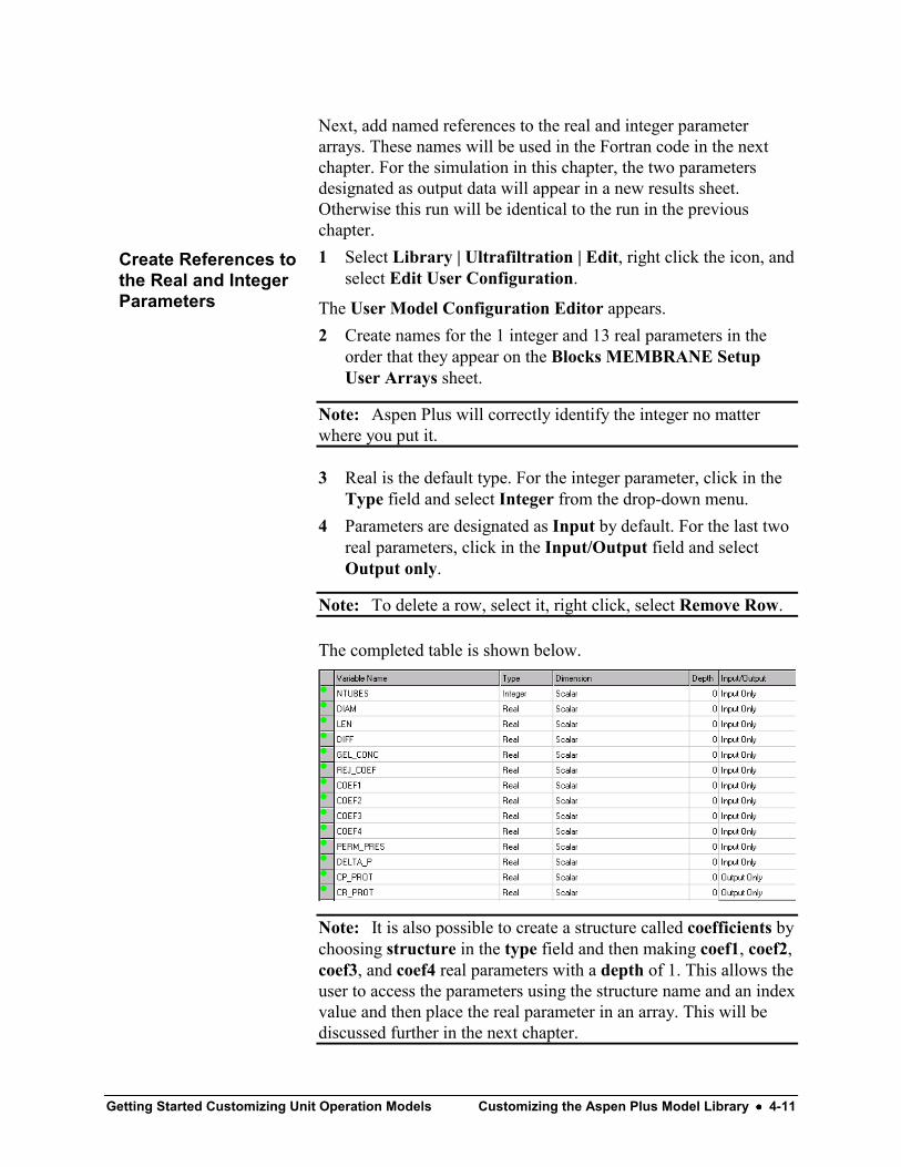
The User Model Configuration Editor appears.2 Create names for the 1 integer and 13 real parameters in the
order that they appear on the Blocks MEMBRANE SetupUser Arrays sheet.
Note: Aspen Plus will correctly identify the integer no matterwhere you put it.
3 Real is the default type. For the integer parameter, click in theType field and select Integer from the drop-down menu.
4 Parameters are designated as Input by default. For the last tworeal parameters, click in the Input/Output field and selectOutput only.
Note: To delete a row, select it, right click, select Remove Row.
The completed table is shown below.
Note: It is also possible to create a structure called coefficients bychoosing structure in the type field and then making coef1, coef2,coef3, and coef4 real parameters with a depth of 1. This allows theuser to access the parameters using the structure name and an indexvalue and then place the real parameter in an array. This will bediscussed further in the next chapter.
Create References tothe Real and IntegerParameters

4-12 •••• Customizing the Aspen Plus Model Library Getting Started Customizing Unit Operation Models
5 Exit the Configuration Editor by closing the window.6 Select Library | Ultrafiltration | Save.7 Exit the Model Library Editor by closing the window.
The new icon and the variable names will now appear wheneveryou use the HollowF model.
Inserting the New Model and Runningthe SimulationDelete the old model and replace it with your new HollowF model,reconnecting the streams, and respecifying the product streamFlash.
The named references on the Configured Variables sheet must besupported by a short Fortran subroutine that you must create,compile, and link along with the user model subroutine Mem2.f.The Model Library Editor will write this new subroutine for you.
Insert the HollowF model, create a new dll file containing the newsubroutine, then run the simulation and examine the results.1 Open Membrane2.apw.2 Press Shift-F5 and click OK twice to reinitialize the
simulation.3 Select Library | References… and select Ultrafiltration.
Your Ultrafiltration library has one category called Membranesand its tab appears in the Model Library.4 On the Process Flowsheet, delete the MEMBRANE block.5 Place a HollowF block on the Process Flowsheet.6 Select the FEED stream, right-click, select Reconnect
Destination.7 Move the cursor over the Feed port and click once to reconnect
the stream.8 Reconnect the RETENTAT stream to the Product port using
the Reconnect Source option. If you accidentally select thePERMEATE stream first, press Esc on the keyboard to cancel.
9 Reconnect the PERMEATE stream. The order matters becausethe first stream connected comes first in the output stream dataarray (SOUT). Once both streams are connected they can beseparated for clarity.
Insert the New Model

Getting Started Customizing Unit Operation Models Customizing the Aspen Plus Model Library •••• 4-13
10 Rename the block, a Hollow Fiber Ultrafiltration Membranewith 180 tubes, HFUM180.
Now that the Process Flowsheet is complete, check the data sheetsfor the HFUM180 block. Make sure all the data included with themodel by default is correct and add the product stream Flashspecification.1 Open the Data Browser and go to the Blocks | HFUM180 |
Setup form.2 Check the Subroutines sheet and make sure the subroutine
name and path to the Excel file are correct.3 Check the User Arrays and Configured Variables sheets. The
two results parameters that you defined for the HollowF modelin the Configuration Editor do not appear on the ConfiguredVariables sheet because they were specified as outputparameters; they will appear on a results sheet.
Note: The data in the User Arrays sheet and ConfiguredVariables sheet are the same. If you change any of the numbers onone sheet, the same change will automatically appear on the othersheet. You can alter the numerical data if you wish and it will bechanged for the particular block that you placed. For future blockplacements, the defaults will remain intact.
Check and Edit SetupSheets

4-14 •••• Customizing the Aspen Plus Model Library Getting Started Customizing Unit Operation Models
4 Go to the Stream Flash sheet and specify a Temperature &pressure Flash for each product stream. No data is needed inthe Flash specifications area.
Now create the Fortran file to handle the new variable names,compile it, create a shared library including your user subroutineand this new subroutine, and run the simulation.1 Select Library | Ultrafiltration | Writable and then Library |
Ultrafiltration | Edit to open the Model Library Editor.2 Select the HollowF model, right-click, and select Edit User
Configuration to open the User Model ConfigurationEditor.
3 Select Fortran | Export and save the Fortran file asMem2Vars.f to the folder that contains Mem2.f (\WorkingFolders\Aspen Plus\Membrane.)
4 Exit the Configuration Editor by closing the window.
Compile, Link, andRun
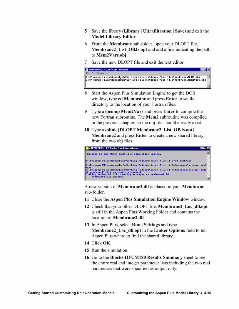
Getting Started Customizing Unit Operation Models Customizing the Aspen Plus Model Library •••• 4-15
5 Save the library (Library | Ultrafiltration | Save) and exit theModel Library Editor.
6 From the Membrane sub-folder, open your DLOPT file,Membrane2_List_OBJs.opt and add a line indicating the pathto Mem2Vars.obj.
7 Save the new DLOPT file and exit the text editor.
8 Start the Aspen Plus Simulation Engine to get the DOSwindow, type cd Membrane and press Enter to set thedirectory to the location of your Fortran files.
9 Type aspcomp Mem2Vars and press Enter to compile thenew Fortran subroutine. The Mem2 subroutine was compiledin the previous chapter; so the obj file should already exist.
10 Type asplink [DLOPT Membrane2_List_OBJs.opt]Membrane2 and press Enter to create a new shared libraryfrom the two obj files.
A new version of Membrane2.dll is placed in your Membranesub-folder.11 Close the Aspen Plus Simulation Engine Window window.12 Check that your other DLOPT file, Membrane2_Loc_dll.opt
is still in the Aspen Plus Working Folder and contains thelocation of Membrane2.dll.
13 In Aspen Plus, select Run | Settings and typeMembrane2_Loc_dll.opt in the Linker Options field to tellAspen Plus where to find the shared library.
14 Click OK.15 Run the simulation.16 Go to the Blocks HFUM180 Results Summary sheet to see
the entire real and integer parameter lists including the two realparameters that were specified as output only.
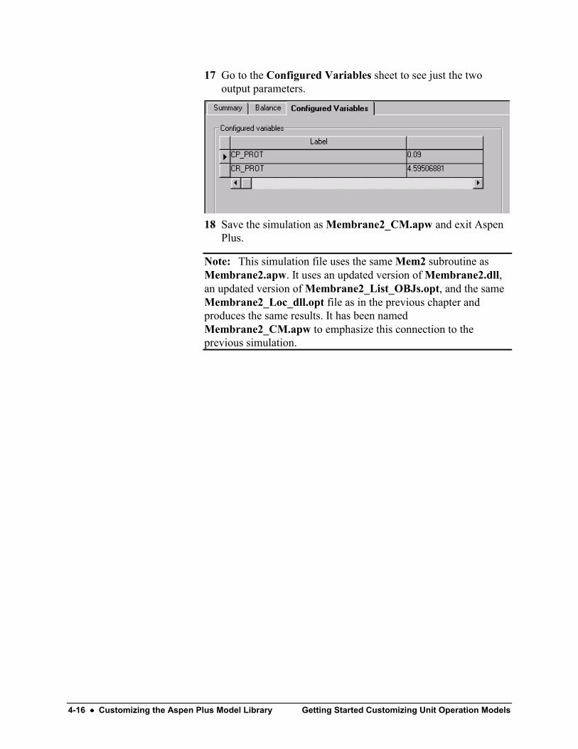
4-16 •••• Customizing the Aspen Plus Model Library Getting Started Customizing Unit Operation Models
17 Go to the Configured Variables sheet to see just the twooutput parameters.
18 Save the simulation as Membrane2_CM.apw and exit AspenPlus.
Note: This simulation file uses the same Mem2 subroutine asMembrane2.apw. It uses an updated version of Membrane2.dll,an updated version of Membrane2_List_OBJs.opt, and the sameMembrane2_Loc_dll.opt file as in the previous chapter andproduces the same results. It has been namedMembrane2_CM.apw to emphasize this connection to theprevious simulation.

Getting Started Customizing Unit Operation Models Creating an Aspen Plus Fortran Model •••• 5-1
Creating an Aspen Plus FortranModel
Excel is useful for testing and troubleshooting a new modelbecause it is self-contained – during the testing phase, it is notnecessary to run Aspen Plus simulations. However, once the modelis developed, you may wish to perform the model calculations inthe user Fortran subroutine and transfer the results directly toAspen Plus.
In this chapter, build a User2 Fortran model to replace the Excelmodel that you developed previously. Use Aspen Plus utilityfunctions that read from and write to the real and integer arraystored with the HollowF customized model. Use the namedreferences (such as “DIAM”) you specified when you created themodel.
The absence of Excel interface functions and the presence of theAspen Plus utility functions make for compact code in the newsubroutine. A complete listing is provided here.
Allow about 30 minutes for this session.
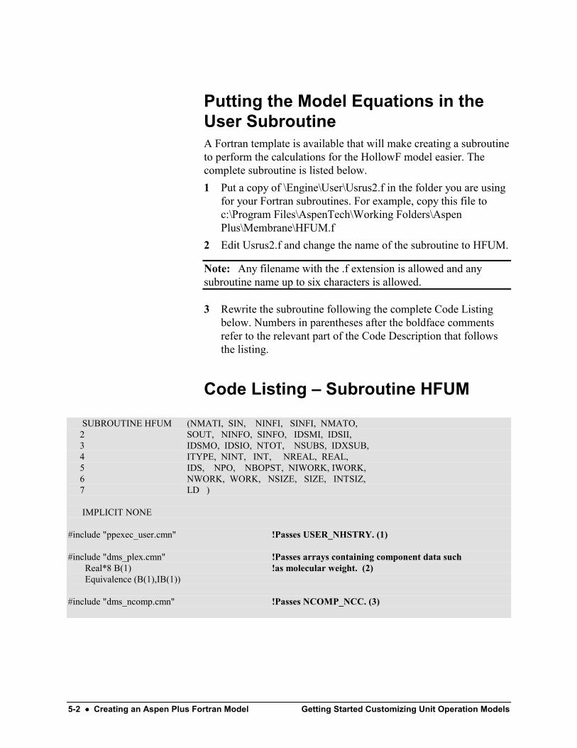
5-2 •••• Creating an Aspen Plus Fortran Model Getting Started Customizing Unit Operation Models
Putting the Model Equations in theUser SubroutineA Fortran template is available that will make creating a subroutineto perform the calculations for the HollowF model easier. Thecomplete subroutine is listed below.1 Put a copy of \Engine\User\Usrus2.f in the folder you are using
for your Fortran subroutines. For example, copy this file toc:\Program Files\AspenTech\Working Folders\AspenPlus\Membrane\HFUM.f
2 Edit Usrus2.f and change the name of the subroutine to HFUM.
Note: Any filename with the .f extension is allowed and anysubroutine name up to six characters is allowed.
3 Rewrite the subroutine following the complete Code Listingbelow. Numbers in parentheses after the boldface commentsrefer to the relevant part of the Code Description that followsthe listing.
Code Listing – Subroutine HFUM
SUBROUTINE HFUM (NMATI, SIN, NINFI, SINFI, NMATO, 2 SOUT, NINFO, SINFO, IDSMI, IDSII, 3 IDSMO, IDSIO, NTOT, NSUBS, IDXSUB, 4 ITYPE, NINT, INT, NREAL, REAL, 5 IDS, NPO, NBOPST, NIWORK, IWORK, 6 NWORK, WORK, NSIZE, SIZE, INTSIZ, 7 LD )
IMPLICIT NONE
#include "ppexec_user.cmn" !Passes USER_NHSTRY. (1)
#include "dms_plex.cmn" !Passes arrays containing component data suchReal*8 B(1) !as molecular weight. (2)Equivalence (B(1),IB(1))
#include "dms_ncomp.cmn" !Passes NCOMP_NCC. (3)

Getting Started Customizing Unit Operation Models Creating an Aspen Plus Fortran Model •••• 5-3
C ------------------- Declare arguments -----------------------------------------------------
INTEGER NMATI, NINFI, NMATO, NINFO, NTOT, + NSUBS, NINT, NPO, NIWORK, NWORK, + NSIZE, NREAL
INTEGER IDSMI(2,NMATI), IDSII(2,NINFI), + IDSMO(2,NMATO), IDSIO(2,NINFO), + IDXSUB(NSUBS), ITYPE(NSUBS), INT(NINT), + IDS(2,3), NBOPST(6,NPO), + IWORK(NIWORK), INTSIZ(NSIZE), LD
REAL*8 SIN(NTOT,NMATI), SINFI(NINFI), + SOUT(NTOT,NMATO), SINFO(NINFO), + WORK(NWORK), SIZE(NSIZE), REAL(NREAL)
C --------------- Declare Local Variables ---------------------------------------------
INTEGER OFFSET, IERR, LDATA, KDIAG, IDX(10), NCP, I, J, INDEX, + LMW, NTUBES, IPERM, IRET,IFAIL
REAL*8DIAM, LEN, DIFF, CG, REJ_COEF, C1, C2, C3, C4, P_PERM, + DELTA_P, RHO, MU, FIN, CIN, PIN, UAVE, RE, SC, + CP, CR, KM, JM, FP, PRET, XMW, X(10), FLOW
C ----------------- Declare Functions --------------------------------------------------
INTEGER USRUTL_GET_REAL_PARAM, !These functions allow access to real and + USRUTL_GET_INT_PARAM, !integer parameters using named references. (4) + USRUTL_SET_REAL_PARAM !To write results data to Aspen Plus. (4)
INTEGER DMS_IFCMNC !Determines offset to universal constant data. (5)
REAL*8 DLOG !Standard Fortran function.
C ----------------------------- Begin Executable Code --------------------------------------------------C ------------------------------Get configured REAL variables from Aspen Plus. ------------------
IFAIL = 0INDEX = 0 !Used for passing a structure. (6)
IERR = USRUTL_GET_REAL_PARAM('DIAM', INDEX, DIAM) !Put Configured Variable called !”DIAM” in local variable DIAM. (7)
IF (IERR .NE. 0) THEN !Write to History file if error. (8)WRITE(USER_NHSTRY,*) ' ERROR FETCHING HYDRAULIC DIAMETER'IFAIL = 1
END IF
IERR = USRUTL_GET_REAL_PARAM('LEN', INDEX, LEN)IF (IERR .NE. 0) THEN
WRITE(USER_NHSTRY,*) ' ERROR FETCHING LENGTH'IFAIL = 1
END IF
IERR = USRUTL_GET_REAL_PARAM('DIFF', INDEX, DIFF)
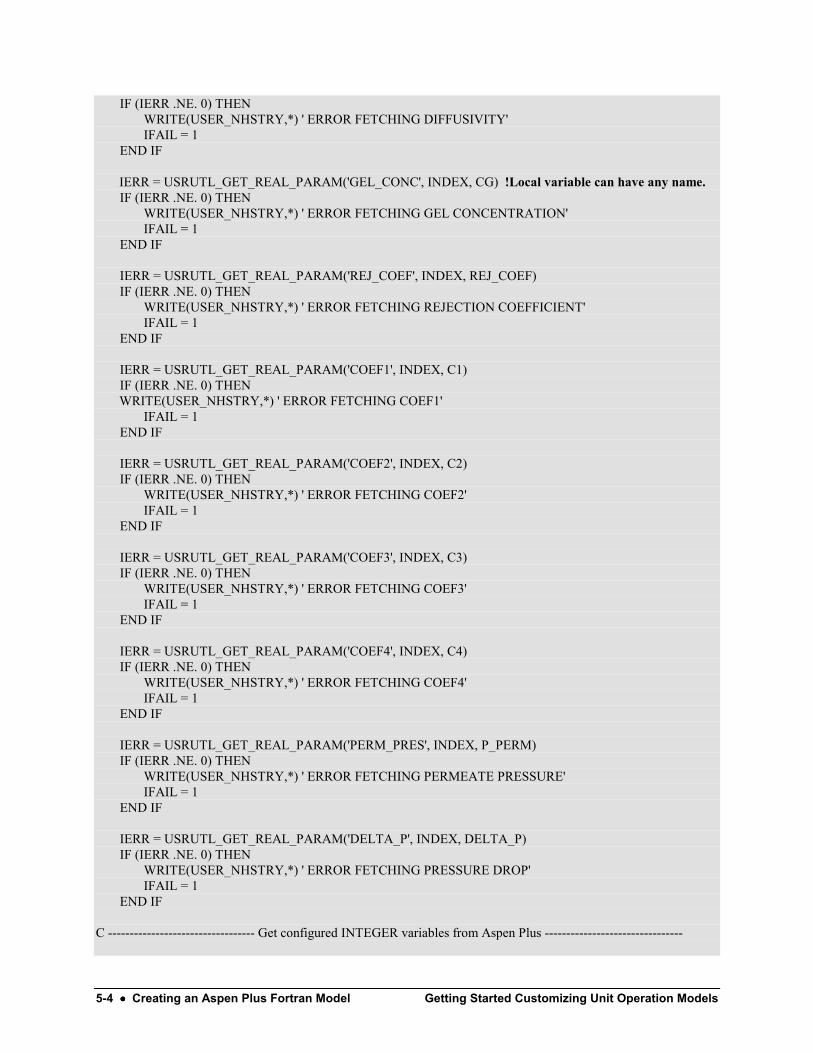
5-4 •••• Creating an Aspen Plus Fortran Model Getting Started Customizing Unit Operation Models
IF (IERR .NE. 0) THENWRITE(USER_NHSTRY,*) ' ERROR FETCHING DIFFUSIVITY'IFAIL = 1
END IF
IERR = USRUTL_GET_REAL_PARAM('GEL_CONC', INDEX, CG) !Local variable can have any name.IF (IERR .NE. 0) THEN
WRITE(USER_NHSTRY,*) ' ERROR FETCHING GEL CONCENTRATION'IFAIL = 1
END IF
IERR = USRUTL_GET_REAL_PARAM('REJ_COEF', INDEX, REJ_COEF)IF (IERR .NE. 0) THEN
WRITE(USER_NHSTRY,*) ' ERROR FETCHING REJECTION COEFFICIENT'IFAIL = 1
END IF
IERR = USRUTL_GET_REAL_PARAM('COEF1', INDEX, C1)IF (IERR .NE. 0) THEN
WRITE(USER_NHSTRY,*) ' ERROR FETCHING COEF1'IFAIL = 1
END IF
IERR = USRUTL_GET_REAL_PARAM('COEF2', INDEX, C2)IF (IERR .NE. 0) THEN
WRITE(USER_NHSTRY,*) ' ERROR FETCHING COEF2'IFAIL = 1
END IF
IERR = USRUTL_GET_REAL_PARAM('COEF3', INDEX, C3)IF (IERR .NE. 0) THEN
WRITE(USER_NHSTRY,*) ' ERROR FETCHING COEF3'IFAIL = 1
END IF
IERR = USRUTL_GET_REAL_PARAM('COEF4', INDEX, C4)IF (IERR .NE. 0) THEN
WRITE(USER_NHSTRY,*) ' ERROR FETCHING COEF4'IFAIL = 1
END IF
IERR = USRUTL_GET_REAL_PARAM('PERM_PRES', INDEX, P_PERM)IF (IERR .NE. 0) THEN
WRITE(USER_NHSTRY,*) ' ERROR FETCHING PERMEATE PRESSURE'IFAIL = 1
END IF
IERR = USRUTL_GET_REAL_PARAM('DELTA_P', INDEX, DELTA_P)IF (IERR .NE. 0) THEN
WRITE(USER_NHSTRY,*) ' ERROR FETCHING PRESSURE DROP'IFAIL = 1
END IF
C ---------------------------------- Get configured INTEGER variables from Aspen Plus --------------------------------

Getting Started Customizing Unit Operation Models Creating an Aspen Plus Fortran Model •••• 5-5
IERR = USRUTL_GET_INT_PARAM('NTUBES', INDEX, NTUBES)IF (IERR .NE. 0) THEN
WRITE(USER_NHSTRY,*) ' ERROR FETCHING NUMBER OF TUBES'IFAIL = 1
END IF
C ---------------------------------------- Calculate viscosity -----------------------------------------------------------
CALL SHS_CPACK(SIN(1,1), NCP, IDX, X, FLOW) !Pack stream data. (9)KDIAG = 4CALL PPMON_VISCL(SIN(NCOMP_NCC+2,1), SIN(NCOMP_NCC+3,1), X, NCP,
+ IDX, NBOPST, KDIAG, MU, IERR) !Calculate viscosity, put result in MU. (9)IF (IERR .NE. 0) THEN
WRITE(USER_NHSTRY, *) ' ERROR EVALUATING VISCOSITY FOR FEED'IFAIL = 1
END IF
IF (IFAIL .EQ. 1) RETURN
C ----------------------------- Get location of molecular weight data.---------------------------------
LMW = DMS_IFCMNC('MW') !Offset to the component molecular weight data. (10)
C ------------------------------------- Model Equations ---------------------------------------------------------------
RHO = SIN(NCOMP_NCC+8,1) / 1000. !Density of feed stream in g/cm^3 [=kg/l]. (11)MU = MU * 10. !Viscosity of feed stream in g/cm/s.FIN = SIN(NCOMP_NCC+1,1) * SIN(NCOMP_NCC+9,1) / RHO * 3600. !Feed flow in l/hr. (11)CIN = SIN(2,1) * B(LMW+2) / FIN * 3600000. !Protein conc. in feed stream in g/l. (11)PIN = SIN(NCOMP_NCC+3,1) / 101325. !Feed stream pressure in atmospheres. (11)
UAVE = FIN / (DIAM**2*3.14*NTUBES/4.) * 1000. / 3600. !Bulk average velocity in cm/s.RE = DIAM * UAVE * RHO / MU !Reynolds number.SC = MU / (RHO * DIFF) !Schmidt number.
CP = CG * (1 – REJ_COEF) !Permeate stream protein conc. in g/l.KM = C1 * RE**C2 * SC**C3 * (DIAM/LEN)**C4 * DIFF/DIAM/100. !Mass xfer coef in m/s.JM = KM * DLOG((CG - CP) / (CIN - CP)) !Volumetric flux in m/s.FP = JM * DIAM * LEN * 3.14 * NTUBES*100*3600/1000. !Permeate stream flow rate in l/hrCR = (CIN - FP/FIN*CP) / (1 - FP/FIN) !Retentate stream protein conc. in g/l.PRET = PIN – DELTA_P !Retentate stream pressure in atm.
C ----------------------------- Assume (incorrectly) PERMEATE stream is first, switch if not. ----------------------------
IPERM = 1IRET = 2IF (IDSMO(1,1) .EQ. 'RETE') THEN !IDSMO is an argument passed to the subroutine.
!It contains the outlet stream ID’s. (12)IPERM = 2IRET = 1
END IF
C --------------------------- Fill SOUT array for PERMEATE stream. -------------------------------------------

5-6 •••• Creating an Aspen Plus Fortran Model Getting Started Customizing Unit Operation Models
SOUT(1,IPERM) = FP * RHO / 3600. / B(LMW+1) !Approximate water flow in kmol/s. (13)SOUT(2,IPERM) = FP * CP / 1000. / 3600. / B(LMW+2) !Protein flow in kmol/s. (13)SOUT(3,IPERM) = SOUT(1,IPERM) + SOUT(2,IPERM) !Total flow in kmol/s. (13)SOUT(4,IPERM) = SIN(4,1) !Temp. unchanged from feed (deg K). (13)SOUT(5,IPERM) = P_PERM * 101325. !Pressure in N/m^2. (13)
C -------------Fill SOUT array for RETENTAT stream using values from PERMEATE stream. ---------------
SOUT(1,IRET) = SIN(1,1) - SOUT(1,IPERM) !Water flow in kmol/s. (13)SOUT(2,IRET) = SIN(2,1) - SOUT(2,IPERM) !Protein flow in kmol/s. (13)SOUT(3,IRET) = SOUT(1,IRET) + SOUT(2,IRET) !Total flow in kmol/s. (13)SOUT(4,IRET) = SIN(4,1) !Temp. unchanged from feed (deg K). (13)SOUT(5,IRET) = PRET * 101325. !Pressure in N/m^2. (13)
C ----------------------------Now set values of the two variables designated as output parameters. ------------
IERR = USRUTL_SET_REAL_PARAM('CP_PROT', INDEX, CP) !The HollowF model was designed!to accept 2 output parameters. (14)
IF (IERR .NE. 0) THENWRITE(USER_NHSTRY,*) ' ERROR STORING PERMEATE PROT CONC'IFAIL = 1
END IF
IERR = USRUTL_SET_REAL_PARAM('CR_PROT', INDEX, CR)IF (IERR .NE. 0) THEN
WRITE(USER_NHSTRY,*) ' ERROR STORING RETENTATE PROT CONC'IFAIL = 1
END IF
RETURNEND
Code Description – Subroutine HFUM1 USER_NHSTRY is the Fortran unit number for the History
File. From Aspen Plus, you can access this file by selectingView | History. This command will open the history file with atext editor and it can be saved using the text editor. Aspen Pluswill also save a History File if you save the simulation as anapw file.
2 The common DMS_PLEX contains data for all componentsincluding the formula, ID, and physical property parameterssuch as molecular weight. The data is accessed by using afunction to find the offset to the location of the data in the B orIB array. For more discussion of the DMS_PLEX common andexamples see the User Models manual and steps 5 and 10 inthis list.

Getting Started Customizing Unit Operation Models Creating an Aspen Plus Fortran Model •••• 5-7
3 NCOMP_NCC is the number of conventional components inthe simulation. In this example, there are two, water andprotein.
4 The three USRUTL functions return an integer which will havethe value zero if there were no errors. These functions allow theuser to pass values between the Fortran subroutine and AspenPlus according to the names defined using the User ModelConfiguration Editor.
5 The integer function DMS_IFCMCN takes a character stringas input (for example, ‘MW’ for molecular weight) and returnsthe offset to an area of the “Plex” data array. For moreinformation and examples, see the User Models manual andstep 10 in this list.
6 INDEX is an array of indices used in the USRUTL functionswhen handling a structure. Its value is irrelevant in the presentexample since none of the data are structures. However, if youcreated a coefficients structure with four elements you couldaccess them using the following code:INTEGER INDEX(1), Ierr, USRUTL_GET_REAL_PARAM, iREAL*8 C(4)..DO i = 1,4
INDEX(1) = iIerr = USRUTL_GET_REAL_PARAM(‘coefficients’,INDEX,C(i))
END DO
The 1-based INDEX array contains only as many elements asthere are levels of structure. Each element must be set once perloop. For example, suppose you have nested structures withstr1 containing str2a, str2b, and str2c. If str2b has five scalarelements and you wish to access the third, set INDEX(1) = 2and INDEX(2) = 3. A scalar element within a structure (forexample, coefficients.coef2) may also be referenced directly byits lowest level name (‘coef2’ in this example) as if it were notin a structure at all: USRUTL_GET_REAL_PARAM(‘coef2’,0, C2).
7 On the Aspen Plus Blocks HFUM180 Setup ConfiguredVariables sheet, the user can see that one of the realparameters is called “DIAM.” The functionUSRUTL_GET_REAL_PARAM retrieves the value of thisparameter and puts it into a local Fortran variable that, in thisexample, is named DIAM. Of course any declared Real*8variable is allowed to hold the value of this parameter.
5-8 •••• Creating an Aspen Plus Fortran Model Getting Started Customizing Unit Operation Models
8 This History File, also discussed in Step 1 above, is a usefulplace for error messages and troubleshooting output statements.For example, a statement likewrite(user_nhstry,*) ‘diam = ‘, diam
might be useful if your calculations aren’t coming out properlyand you want zero in on the problem.
9 The user can call physical property monitors such asPPMON_VISCL to access the Aspen Plus Physical Propertysystem. The PPMON subroutines require the streaminformation in “packed” form (that is, a reduced list ofcomponent mole fractions with the zeroes removed) producedby a packing utility such as SHS_CPACK. For moreinformation about accessing physical properties see Chapters 3and 4 of the User Models manual.
10 For a list of the names to feed to DMS_IFCMNC in order toretrieve component data from Aspen Plus, see Chapter 6 of theUser Models manual. In this example, the offset (LMW) to themolecular weight data is obtained using the string ‘MW.’ Themolecular weight of the first component listed by the user onthe Aspen Plus Components Specifications Selection sheet(water) is stored in B(LMW + 1). The molecular weight ofprotein (really lysine) is stored in B(LMW + 2).
11 The input (feed) stream array SIN contains NCOMP_NCC+9elements for each feed stream. In this example there is only onefeed stream so the second index is always 1. The first indexmay be 1 through 11 since there are two components. The firsttwo elements are the mole flows in kmol/s for water andprotein. The following nine elements are total mole flow,temperature, pressure, enthalpy, vapor fraction, liquid fraction,entropy, density, and molecular weight of the stream. They arelisted in Appendix C of the User Models manual and are in SIunits. Since the model equations in this example use otherunits, conversions must be performed.
12 The argument list for User 2 models is documented in Chapter5 of the User Models manual. IDSMO is an array withdimension (2, NMATO) where NMATO is the number ofmaterial outlet streams. For each stream, there are 2 four-character labels. In this example, the streams are distinguishedby the first four letters in the label of each (RETE and PERM).Alternatively, the programmer can instruct users to alwaysconnect the Retentate stream first.
13 The SOUT array has the same structure as the SIN array. Itcontains the mole flow, temperature, pressure, and other data
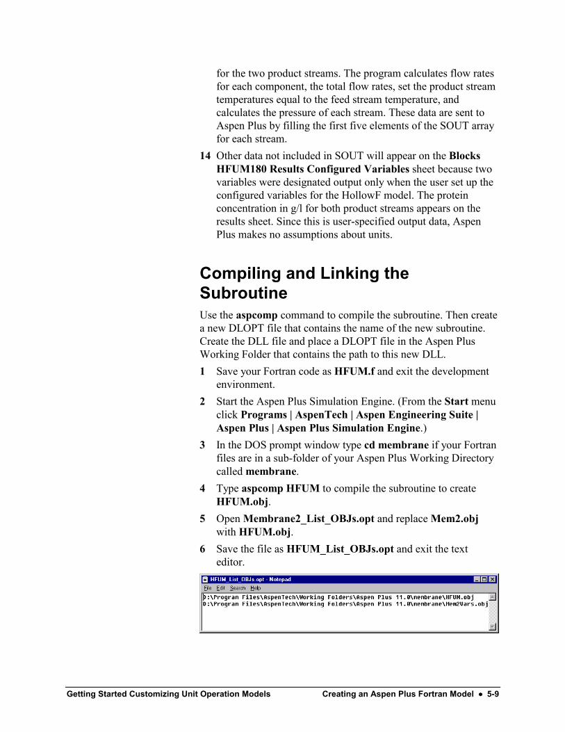
Getting Started Customizing Unit Operation Models Creating an Aspen Plus Fortran Model •••• 5-9
for the two product streams. The program calculates flow ratesfor each component, the total flow rates, set the product streamtemperatures equal to the feed stream temperature, andcalculates the pressure of each stream. These data are sent toAspen Plus by filling the first five elements of the SOUT arrayfor each stream.
14 Other data not included in SOUT will appear on the BlocksHFUM180 Results Configured Variables sheet because twovariables were designated output only when the user set up theconfigured variables for the HollowF model. The proteinconcentration in g/l for both product streams appears on theresults sheet. Since this is user-specified output data, AspenPlus makes no assumptions about units.
Compiling and Linking theSubroutineUse the aspcomp command to compile the subroutine. Then createa new DLOPT file that contains the name of the new subroutine.Create the DLL file and place a DLOPT file in the Aspen PlusWorking Folder that contains the path to this new DLL.1 Save your Fortran code as HFUM.f and exit the development
environment.2 Start the Aspen Plus Simulation Engine. (From the Start menu
click Programs | AspenTech | Aspen Engineering Suite |Aspen Plus | Aspen Plus Simulation Engine.)
3 In the DOS prompt window type cd membrane if your Fortranfiles are in a sub-folder of your Aspen Plus Working Directorycalled membrane.
4 Type aspcomp HFUM to compile the subroutine to createHFUM.obj.
5 Open Membrane2_List_OBJs.opt and replace Mem2.objwith HFUM.obj.
6 Save the file as HFUM_List_OBJs.opt and exit the texteditor.

5-10 •••• Creating an Aspen Plus Fortran Model Getting Started Customizing Unit Operation Models
7 In the DOS window of the Aspen Plus Simulation Engine, typeasplink [dlopt HFUM_List_OBJs.opt] HFUM to createHFUM.dll.
8 From the Aspen Plus Working Folder, openMembrane2_Loc_dll.opt and replace Membrane2.dll withHFUM.dll.
9 Save the file as HFUM_Loc_dll.opt and exit the text editor.
Running the SimulationUse the membrane2_cm.apw simulation from the previouschapter. Since your model calculations will be performed by theFortran subroutine, remove the reference to the Excel file. Thenenter the name of the DLOPT file containing the location of the dllfile and run the simulation.1 Open membrane2_cm.apw.2 Select Run | Reinitialize (or press Shift-F5) and click OK
twice.3 Go to the Setup Specifications Global sheet and change the
title to HFUM.4 Go to the Blocks HFUM180 Setup Subroutines sheet, change
the name of the Fortran subroutine to HFUM and delete thereference to the Excel file.
5 Select Run | Settings, type HFUM_Loc_dll.opt in the LinkerOptions field, and click OK.
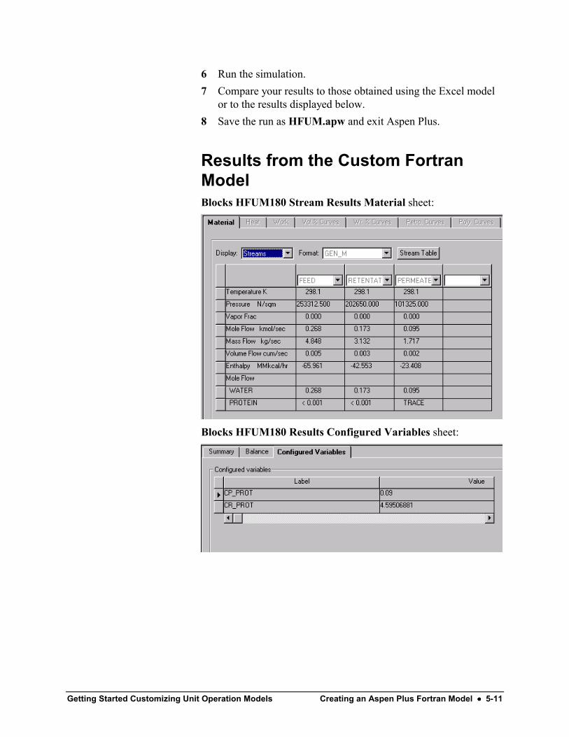
Getting Started Customizing Unit Operation Models Creating an Aspen Plus Fortran Model •••• 5-11
6 Run the simulation.7 Compare your results to those obtained using the Excel model
or to the results displayed below.8 Save the run as HFUM.apw and exit Aspen Plus.
Results from the Custom FortranModelBlocks HFUM180 Stream Results Material sheet:
Blocks HFUM180 Results Configured Variables sheet:

5-12 •••• Creating an Aspen Plus Fortran Model Getting Started Customizing Unit Operation Models
Getting Started Customizing Unit Operation Models Creating an Aspen Plus Custom Form •••• 6-1
Creating an Aspen Plus CustomForm
Creating graphical forms using Microsoft Visual Basic is the lastlevel of customization for supporting custom models in AspenPlus. Configured variables that were defined for these models canbe linked into these forms.
The ability to create forms combined with the templatingcapabilities that you used in the previous chapter is a very powerfulcustomization capability. It is now possible to create forms for anexisting plant unit that hides design parameters for users interestedin performing rating only calculations for example. These formsare easily inserted into Aspen Plus by registering the OCX filecreated by Visual Basic using the Aspen Plus ApwnSetup utility.Visual Basic template files are provided with Aspen Plus to reducethe amount of time required to develop custom forms. Fieldscommonly used by the Aspen Plus GUI can be applied to a newsheet by dragging it from a Controls Toolbox.
In this example, create a special Blocks BLOCKNAMEInput_And_Results form containing two sheets: an Input sheetthat provides access to two important membrane parameters and aResults sheet that contains results of particular interest. Include thenew form as an addition to the usual forms associated with theHollowF model and create a new model that contains the specialform.
Allow about 40 minutes for this session.

6-2 •••• Creating an Aspen Plus Custom Form Getting Started Customizing Unit Operation Models
Setting Up the Visual BasicEnvironmentUse Visual Basic to create your form (an OCX file), then create atext (OCR) file with specifications, run a program thatautomatically sets up the Aspen Plus/Visual Basic interface, createa model that will “own” the form, and test the new form.
It is important to keep track of file names, project and controlnames, and the model name so that the interface works. Thisexample uses literal naming such as ProjectFile, ProjectName, andModelName. However, the example uses ordinary names for theform and its two sheets: FormName = Input_And_Results andSheet1Name = Input, Sheet2Name = Results.
Aspen Plus provides a Visual Basic project file (.vbp), two VisualBasic control files (.ctl), and two graphics files (.ctx; to support thecontrol files) to define the development environment for creatingAspen Plus GUI forms.
Use these template files to set up an environment in which you caneasily create custom forms that have the same look andfunctionality as the standard Aspen Plus forms.1 Create a new folder to use as a Visual Basic Working Folder.
For example, create d:\Program Files\AspenTech\WorkingFolders\Aspen Plus\VB
2 Copy the following files from the GUI\xeq folder of the AspenPlus installation to your VB folder:
tabtemplate.ctltabtemplate.ctxformtemplate.ctlformtemplate.ctx
3 Copy the following file from the GUI\xeq folder of theAPrSystem installation to your VB folder:
Template.vbp
4 Open the Visual Basic project by double clickingTemplate.vbp.
5 Save the project as ProjectFile.vbp.6 Select Project | MyModel Properties… and change the
Project Name to ProjectName.
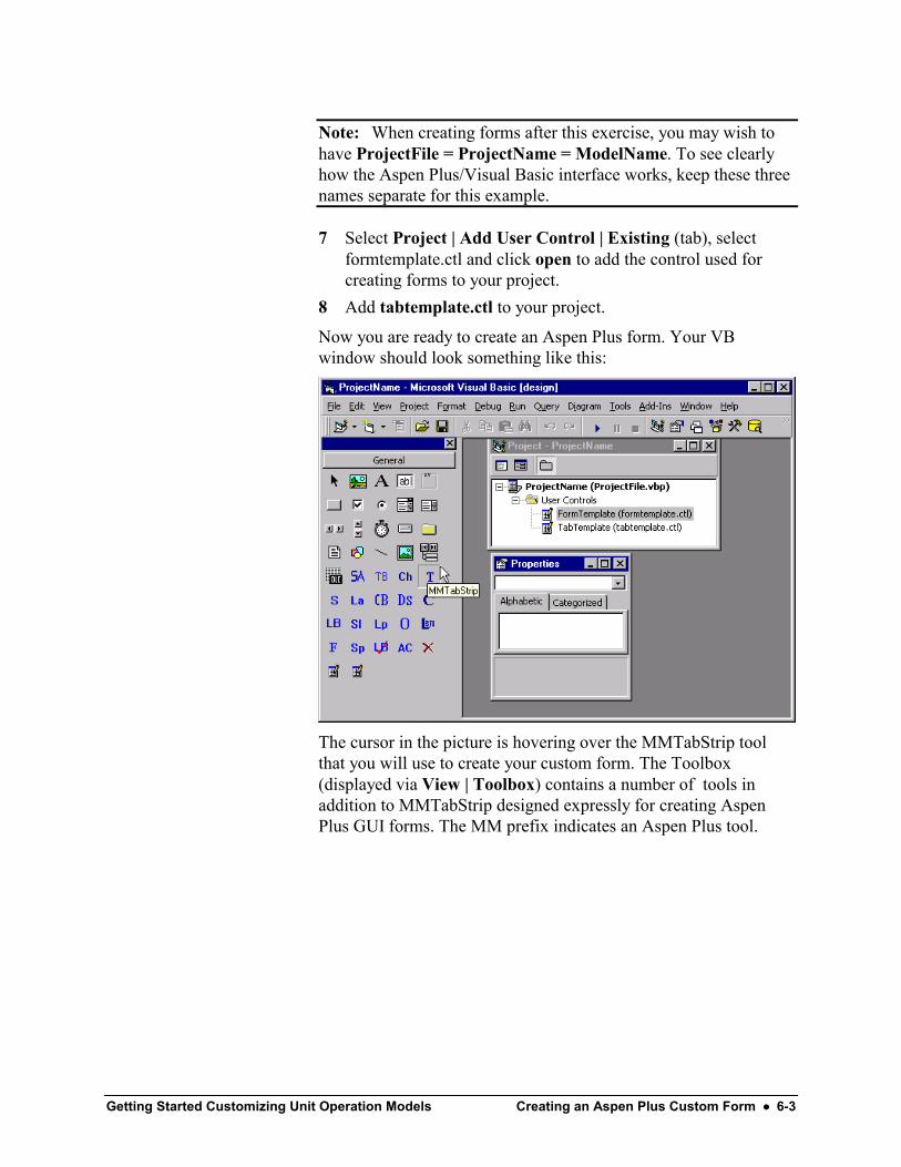
Getting Started Customizing Unit Operation Models Creating an Aspen Plus Custom Form •••• 6-3
Note: When creating forms after this exercise, you may wish tohave ProjectFile = ProjectName = ModelName. To see clearlyhow the Aspen Plus/Visual Basic interface works, keep these threenames separate for this example.
7 Select Project | Add User Control | Existing (tab), selectformtemplate.ctl and click open to add the control used forcreating forms to your project.
8 Add tabtemplate.ctl to your project.
Now you are ready to create an Aspen Plus form. Your VBwindow should look something like this:
The cursor in the picture is hovering over the MMTabStrip toolthat you will use to create your custom form. The Toolbox(displayed via View | Toolbox) contains a number of tools inaddition to MMTabStrip designed expressly for creating AspenPlus GUI forms. The MM prefix indicates an Aspen Plus tool.
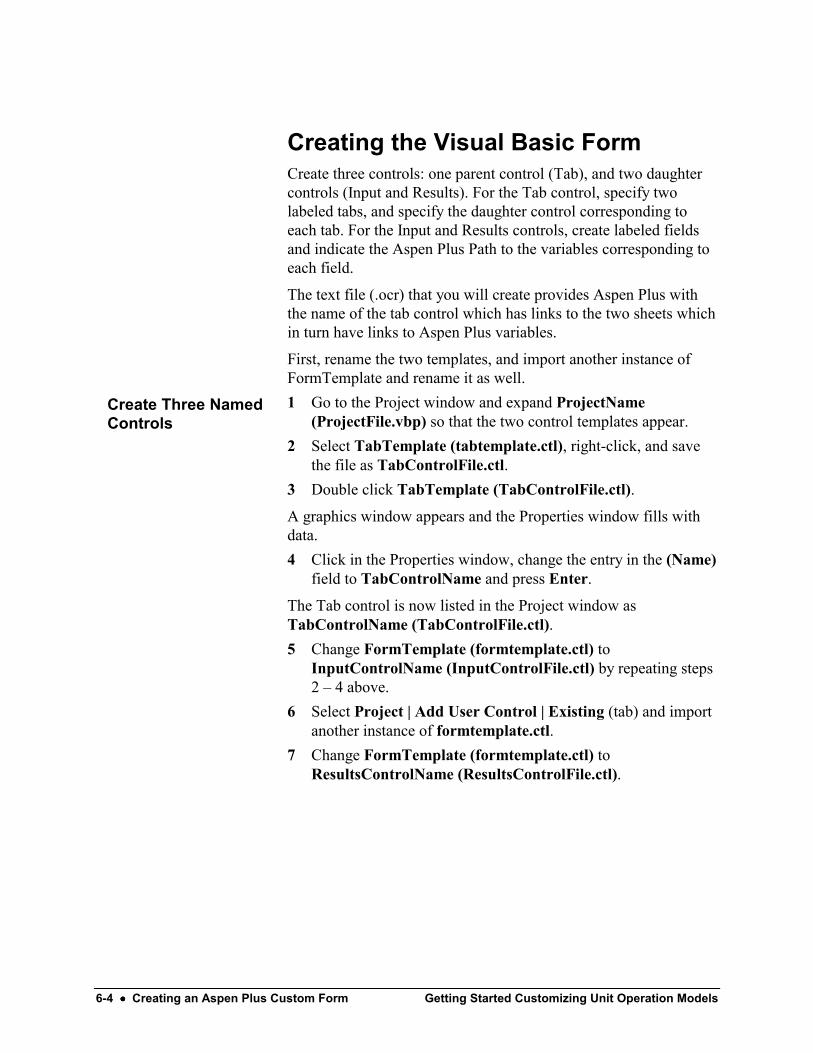
6-4 •••• Creating an Aspen Plus Custom Form Getting Started Customizing Unit Operation Models
Creating the Visual Basic FormCreate three controls: one parent control (Tab), and two daughtercontrols (Input and Results). For the Tab control, specify twolabeled tabs, and specify the daughter control corresponding toeach tab. For the Input and Results controls, create labeled fieldsand indicate the Aspen Plus Path to the variables corresponding toeach field.
The text file (.ocr) that you will create provides Aspen Plus withthe name of the tab control which has links to the two sheets whichin turn have links to Aspen Plus variables.
First, rename the two templates, and import another instance ofFormTemplate and rename it as well.1 Go to the Project window and expand ProjectName
(ProjectFile.vbp) so that the two control templates appear.2 Select TabTemplate (tabtemplate.ctl), right-click, and save
the file as TabControlFile.ctl.3 Double click TabTemplate (TabControlFile.ctl).
A graphics window appears and the Properties window fills withdata.4 Click in the Properties window, change the entry in the (Name)
field to TabControlName and press Enter.
The Tab control is now listed in the Project window asTabControlName (TabControlFile.ctl).5 Change FormTemplate (formtemplate.ctl) to
InputControlName (InputControlFile.ctl) by repeating steps2 – 4 above.
6 Select Project | Add User Control | Existing (tab) and importanother instance of formtemplate.ctl.
7 Change FormTemplate (formtemplate.ctl) toResultsControlName (ResultsControlFile.ctl).
Create Three NamedControls

Getting Started Customizing Unit Operation Models Creating an Aspen Plus Custom Form •••• 6-5
After cleaning up, your window will look something like this:
Next, build the Tab control. Use the MMTabStrip tool and maketwo tabs (the default is three so you’ll have to delete one) linked tothe Input and Results sheets.1 From your VB project, maximize the TabControlName
window.2 From the toolbox on the left-hand side of the VB window, click
.3 Move the cursor onto the drawing area in the
TabControlName window (it becomes a crosshair).4 Click and drag diagonally across the drawing area and release
the mouse to create a box with three tabs.
This “box with three tabs” is called a tab strip.
5 Select the tab strip, right-click, and select Properties.
Build the Tab Control

6-6 •••• Creating an Aspen Plus Custom Form Getting Started Customizing Unit Operation Models
The Property Pages dialog box appears.6 In the Caption field, type Input.7 Create the link to the Input control by typing
ProjectName.InputControlName in the FormName field.
Property Pages dialog, close-up view:
8 Advance the Current Tab field from 0 to 1 by clicking the uparrow to the right of the field.
9 In the Caption field, type Results.10 Create the link to the Results control by typing
ProjectName.ResultsControlName in the FormName field.11 Advance the Current Tab field to 2.12 Click Remove Tab as you need only two tabs, the 0th and 1st.13 Click OK.

Getting Started Customizing Unit Operation Models Creating an Aspen Plus Custom Form •••• 6-7
The tab strip, (most-recently-edited tab is bold):
Note: The MMTabStrip object selected above and the UserControl object (selected if you click in the drawing area outside thetab strip) are separate objects with separate properties.
14 Reduce the TabControlName window so that you can accessthe other controls.
15 Select TabControlName (TabControlFile.ctl) in the projectwindow, right-click, and select Save TabControlFile.ctl

6-8 •••• Creating an Aspen Plus Custom Form Getting Started Customizing Unit Operation Models
Next, build the Input control. Use the MMFrame tool to create aframe for two input fields. Then use the MMLBUText tool tocreate the two fields – one labeled Channel Hydraulic Diameterand the other labeled Channel Length.
In the HollowF model, you created named variables for themembrane parameters and they appeared on the ConfiguredVariables sheet. Now two of these variables will also appear onyour new Input sheet. You will specify the Aspen Plus paths tothese variables in the Input control you are about to build.1 Maximize the InputControlName window.
2 From the toolbox, click .3 Click and drag in the drawing area of the Input control to create
a Frame.4 Select View | Properties Window or press F4 to open the
Properties window.5 Enter Membrane Parameters in the Caption field.
The Properties window :
6 Close the Properties window.
7 From the toolbox, click .8 Click and drag in the upper half of the Frame to create a field
area. It won’t look nice right away.9 Select the new field area, right-click, and select Properties.
Build the InputControl
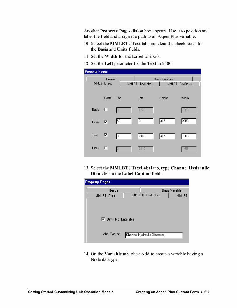
Getting Started Customizing Unit Operation Models Creating an Aspen Plus Custom Form •••• 6-9
Another Property Pages dialog box appears. Use it to position andlabel the field and assign it a path to an Aspen Plus variable.10 Select the MMLBTUText tab, and clear the checkboxes for
the Basis and Units fields.11 Set the Width for the Label to 2350.12 Set the Left parameter for the Text to 2400.
13 Select the MMLBTUTextLabel tab, type Channel HydraulicDiameter in the Label Caption field.
14 On the Variable tab, click Add to create a variable having aNode datatype.

6-10 •••• Creating an Aspen Plus Custom Form Getting Started Customizing Unit Operation Models
15 In the first Path column, enter main, Input, User Table, DIAMrespectively into the first four cells. Use a space between thewords User and Table.
The full path to variable you defined as DIAM when you createdthe HollowF model is shown below in the Aspen Plus VariableExplorer window which is accessed by via the Tools | VariableExplorer… command. The variable main used above isautomatically assigned to the path to the block containing yourform: Application.Tree.Data.Blocks.B1 in this example. This isimportant because any given block could have any user-chosenname at run time.
16 Click OK to close the Property Pages dialog box.

Getting Started Customizing Unit Operation Models Creating an Aspen Plus Custom Form •••• 6-11
17 Select the Channel Hydraulic Diameter field area and resizeit so that it doesn’t take up too much space in the MembraneParameters frame.
18 Click in the tool box.19 Click and drag in the frame to create a small label.20 Select the label, right-click, select Properties and enter cm in
the Caption field..21 Resize the label and move it to the right of the Channel
Hydraulic Diameter field.22 Reduce the InputControlName window.23 Select InputControlName (InputControlFile.ctl) in the
Project window, right-click, and select Save.24 Repeat steps 7-23 and create a Channel Length field mapped to
the LEN variable with path: main.Input.User Table.LEN.
The eventual Blocks BLOCKNAME Input_And_Results Inputsheet looks like this:
Next, build the Results control. An abbreviated procedure is givenbelow – refer to steps 7 – 21. Create two fields, Permeate ProteinConcentration and Retentate Protein Concentration. Specifypaths to the two Output only variables, CP_PROT andCR_PROT, that you defined in the HollowF model.1 Make a frame called Membrane Performance.2 Make a field for Permeate Protein Concentration and map the
variable to: main, Output, User Tree, CP_PROT.3 Make a field for Retentate Protein Concentration and map the
variable to: main, Output, User Tree, CR_PROT.
Build the ResultsControl

6-12 •••• Creating an Aspen Plus Custom Form Getting Started Customizing Unit Operation Models
4 Add the concentration units (g/l) next to the field.
The eventual Blocks BLOCKNAME Input_And_ResultsResults sheet looks like this:
5 Save the ResultsControlFile.ctl file.6 Save the Visual Basic Project.
The finished Project:
7 Select File | Make ProjectFile.ocx… and click OK to createthe ocx file that will be registered with the operating systemand thereby integrated with Aspen Plus.
8 Exit the VB development environment.

Getting Started Customizing Unit Operation Models Creating an Aspen Plus Custom Form •••• 6-13
Integrating Forms with Aspen PlusThe connection between Aspen Plus and your custom form isaccomplished by means of two files. The OCX file created abovecontains the actual form. A text file with the OCR extension willcontain specifications for the form.
The OCR file contains the name of the unit operation model thatuses the form, the name of the form as it will appear on the DataBrowser menu tree, the name of the tab control, and informationspecifying the placement of the new form in the list of forms.
Your new form applies only to a USER2-based custom model(called ModelName in this example) for a hollow fiberultrafiltration membrane. The new form should appear only withthis particular model. The ModelName model should contain allthe usual USER2 forms. The do this:Rename the OCX file to ModelName.ocx.Create an OCR file called ModelName.ocr.Put the specification for the new form into your OCR file.Copy and paste specifications for the usual USER2 forms from the Aspen PlusOCR files in GUI\forms to your OCR file.Put copies of your OCR and OCX file in GUI\forms.Use ApwnSetup.exe in GUI\xeq to register your OCX file (the OCR file isprocessed automatically).
A step-by-step procedure is provided below.1 Rename ProjectFile.ocx to ModelName.ocx.2 Create a text file called ModelName.ocr with the first line as
shown below. Letters in the name of the unit operation model(in this case MODELNAME) must ALL be capitalized even ifthe actual Aspen Plus model is called ModelName.
A form called Input_And_Results will appear in the Blocks folderon the Data Browser menu tree when a ModelName block isplaced in the Process Flowsheet. Aspen Plus will use the tabcontrol object called ProjectName.TabControlName to create theform. The number “5” is for position in the form list and thenumber “1” indicates a tabbed form.
Create OCR and OCXFiles for Your Model
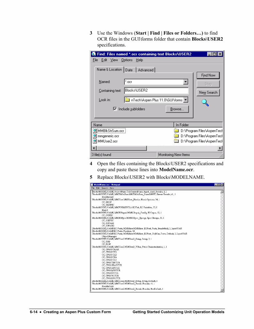
6-14 •••• Creating an Aspen Plus Custom Form Getting Started Customizing Unit Operation Models
3 Use the Windows (Start | Find | Files or Folders…) to findOCR files in the GUI\forms folder that contain Blocks\USER2specifications.
4 Open the files containing the Blocks\USER2 specifications andcopy and paste these lines into ModelName.ocr.
5 Replace Blocks\USER2 with Blocks\MODELNAME.
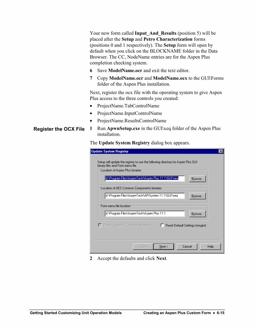
Getting Started Customizing Unit Operation Models Creating an Aspen Plus Custom Form •••• 6-15
Your new form called Input_And_Results (position 5) will beplaced after the Setup and Petro Characterization forms(positions 0 and 1 respectively). The Setup form will open bydefault when you click on the BLOCKNAME folder in the DataBrowser. The CC, NodeName entries are for the Aspen Pluscompletion checking system.6 Save ModelName.ocr and exit the text editor.7 Copy ModelName.ocr and ModelName.ocx to the GUI\Forms
folder of the Aspen Plus installation.
Next, register the ocx file with the operating system to give AspenPlus access to the three controls you created:• ProjectName.TabControlName• ProjectName.InputControlName• ProjectName.ResultsControlName1 Run ApwnSetup.exe in the GUI\xeq folder of the Aspen Plus
installation.
The Update System Registry dialog box appears.
2 Accept the defaults and click Next.
Register the OCX File

6-16 •••• Creating an Aspen Plus Custom Form Getting Started Customizing Unit Operation Models
The Register Forms dialog box appears listing all OCX files in theGUI\Forms folder.3 Click Deselect All to clear all the selections.4 In the Product specific forms list, scroll down to
ModelName.ocx and click it so that only it is selected.5 Select Update Data Browser Menu since you are only adding
a form to a previously-built menu.
6 Click Next.
The Data Browser updates (new entries are made in the SystemRegistry) so that Aspen Plus has access to the new form. TheRegister PlotWizard dialog box appears.7 Click Deselect All and then click Finish since you have no
new plot wizard files to register.8 Click OK when ApwnSetup.exe announces success.
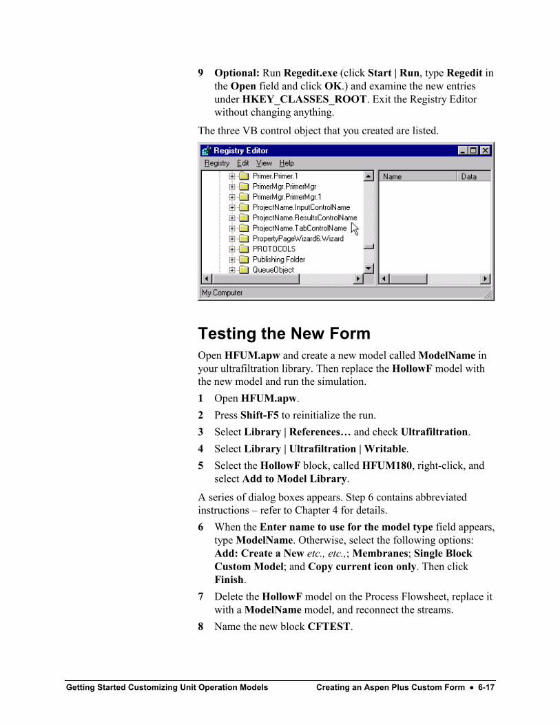
Getting Started Customizing Unit Operation Models Creating an Aspen Plus Custom Form •••• 6-17
9 Optional: Run Regedit.exe (click Start | Run, type Regedit inthe Open field and click OK.) and examine the new entriesunder HKEY_CLASSES_ROOT. Exit the Registry Editorwithout changing anything.
The three VB control object that you created are listed.
Testing the New FormOpen HFUM.apw and create a new model called ModelName inyour ultrafiltration library. Then replace the HollowF model withthe new model and run the simulation.1 Open HFUM.apw.2 Press Shift-F5 to reinitialize the run.3 Select Library | References… and check Ultrafiltration.4 Select Library | Ultrafiltration | Writable.5 Select the HollowF block, called HFUM180, right-click, and
select Add to Model Library.
A series of dialog boxes appears. Step 6 contains abbreviatedinstructions – refer to Chapter 4 for details.6 When the Enter name to use for the model type field appears,
type ModelName. Otherwise, select the following options:Add: Create a New etc., etc.,; Membranes; Single BlockCustom Model; and Copy current icon only. Then clickFinish.
7 Delete the HollowF model on the Process Flowsheet, replace itwith a ModelName model, and reconnect the streams.
8 Name the new block CFTEST.

6-18 •••• Creating an Aspen Plus Custom Form Getting Started Customizing Unit Operation Models
9 Open the Data Browser and go to the Blocks CFTESTInput_And_Results Input sheet. Note the data in the twofields. Check the Results sheet. There is no data there yet.
10 Go to the Blocks CFTEST Setup Subroutines sheet and typeHFUM in the Model field and eliminate the reference to theExcel file.
11 Go to the Blocks CFTEST Setup Stream Flash sheet and setTemperature & pressure flashes for both product streams.
12 Select Run | Settings and type HFUM_Loc_dll.opt in theLinker Options field.
13 Run the simulation.14 Go to the Blocks CFTEST Input_And _Results Results sheet
to check the results.15 Go to the Blocks CFTEST Input_And_Results Input sheet,
change the input values of the two parameters, run thesimulation again, and click the results tab to see the changes.
16 Save the simulation as HFUM_CF.apw and exit Aspen Plus.
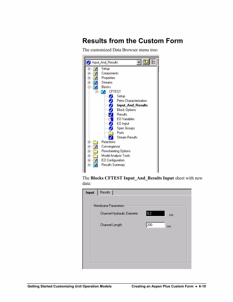
Getting Started Customizing Unit Operation Models Creating an Aspen Plus Custom Form •••• 6-19
Results from the Custom FormThe customized Data Browser menu tree:
The Blocks CFTEST Input_And_Results Input sheet with newdata:

6-20 •••• Creating an Aspen Plus Custom Form Getting Started Customizing Unit Operation Models
The Blocks CFTEST Input_And_Results Results sheet after therun with new data: