GESTURE RECOGNITION AND MIMICKING IN A HUMANOID ROBOT By Sean Michael Begley
189
GESTURE RECOGNITION AND MIMICKING IN A HUMANOID ROBOT By Sean Michael Begley Thesis Submitted to the Faculty of the Graduate School of Vanderbilt University in partial fulfillment of the requirements for the degree of MASTER OF SCIENCE in Electrical Engineering May, 2008 Nashville, Tennessee Approved: Professor Richard A. Peters II Professor D. Mitchell Wilkes
Transcript of GESTURE RECOGNITION AND MIMICKING IN A HUMANOID ROBOT By Sean Michael Begley

GESTURE RECOGNITION AND MIMICKING IN A HUMANOID ROBOT
By
Sean Michael Begley
Thesis
Submitted to the Faculty of the
Graduate School of Vanderbilt University
in partial fulfillment of the requirements
for the degree of
MASTER OF SCIENCE
in
Electrical Engineering
May, 2008
Nashville, Tennessee
Approved:
Professor Richard A. Peters II
Professor D. Mitchell Wilkes

ii
To my mother and father who have always supported me in everything I have every
wanted to do

iii
ACKNOWLEDGEMENTS
This work, and in fact the degree for which I am to receive, would not have been
possible without the financial, and academic, support of Vanderbilt University. I am
grateful to the University for granting me a full tuition scholarship allowing me to pursue
my studies further. It would have been infinitely more difficult for me to complete this
degree without said funding.
My family, of course, has always been truly loyal. While it goes without saying, I
would like take this opportunity to thank them for their unending support and say that I
love them. My father, Brian, whose footsteps I have followed, has provided me with the
greatest of role models. My mother, Margo, has always had my best interests at heart
and continues to do anything, and everything, she can to encourage me in my varied
endeavors. To the rest of my family I thank you as well. To grandparents, aunts,
uncles, cousins, and my brother, you have always supported me and it has shaped who
I have become.
I would like to thank the entirety of the engineering faculty and staff. Throughout
my six year tenure at Vanderbilt I have learned an immense amount and grown as an
individual. Each teacher that I have had the privilege of working with has added to my
life. In particular I would like to thank Dr. Richard Alan Peters II. I first met Dr. Peters
as a junior after enquiring about doing some independent study work with him. Since
them he has been my constant friend and advisor. Dr. Peters worked with me through
three independent studies and was instrumental in my coming back to Vanderbilt to
earn my Master’s Degree. Since then he has always supported me, not only in my

iv
research, but in my life as a whole. I am continually impressed by the effort he puts into
helping others and the selfless attitude he takes towards his student’s wellbeing, putting
them ahead of himself.

v
TABLE OF CONTENTS
Page
ACKNOWLEDGEMENTS ............................................................................................... iii
TABLE OF CONTENTS .................................................................................................. v
LIST OF FIGURES........................................................................................................ viii
LIST OF ACRONYMS..................................................................................................... x
I. INTRODUCTION.................................................................................................. 1
I.1. Problem Statement ........................................................................................... 2
I.2. Background & Motivation .................................................................................. 4
II. THE COMPLETE SYSTEM.................................................................................. 5
II.1. ISAC ................................................................................................................. 5
II.1.1. Cameras .................................................................................................... 5
II.1.2. Arms .......................................................................................................... 8
II.1.3. Controllers ............................................................................................... 18
II.2. OpenCV .......................................................................................................... 20
II.3. CalTech Image Calibration Toolbox for Matlab............................................... 22
II.4. Previously Developed Code............................................................................ 23
II.4.1. PXC Drivers ............................................................................................. 23
II.4.2. Connected Components Extraction ......................................................... 25
II.4.3. New Neural Network / PID Controller....................................................... 26
III. THE COMPLETE SYSTEM................................................................................ 29
III.1. Vision Subsystem ........................................................................................... 31
III.1.1. Object Detection ...................................................................................... 31

vi
III.1.2. Haar Face Detection................................................................................ 34
III.1.3. Object Tracking........................................................................................ 37
III.1.4. Calculating 3D Locations ......................................................................... 40
III.1.5. drawTargets Function .............................................................................. 44
III.2. Processing Subsystem ................................................................................... 45
III.2.1. avgFaceLoc Function............................................................................... 48
III.2.2. flipY Function ........................................................................................... 50
III.2.3. Filtering the Coordinates.......................................................................... 53
III.2.4. Compressing the Coordinates ................................................................. 61
III.2.5. Fitting the Coordinates to ISAC’s Workspace .......................................... 66
III.2.6. Calculating Joint Angles........................................................................... 71
III.2.7. interpolateAngles Function ...................................................................... 78
III.2.8. Uploading The Coordinates To ISAC’s Control Systems......................... 80
III.3. Control/Arm System........................................................................................ 82
III.3.1. The Controller .......................................................................................... 82
III.3.2. The Modifications..................................................................................... 83
III.3.3. Integration with the Vision & Processing Systems ................................... 83
IV. EXPERIMENT .................................................................................................... 85
IV.1. Goals........................................................................................................... 85
IV.2. Procedure.................................................................................................... 86
IV.3. Results ........................................................................................................ 87
IV.4. Discussion ................................................................................................... 87
V. WRAP-UP........................................................................................................... 90

vii
V.1. Conclusion ...................................................................................................... 90
V.2. Recommendations for Future Work ................................................................ 90
V.2.1. Improvements to the Current System ...................................................... 91
V.2.2. Tangent Projects Built on the Current System......................................... 93
REFERENCES.............................................................................................................. 96
APPENDIX .................................................................................................................. 100

viii
LIST OF FIGURES
Figure 1: ISAC's Eyes ..................................................................................................... 6
Figure 2: Single Camera FOV ......................................................................................... 7
Figure 3: Stereopsis FOV................................................................................................ 8
Figure 4: Rubbertuator .................................................................................................... 8
Figure 5: ISAC's Left Arm.............................................................................................. 11
Figure 6: 2 Pair Muscles Configuration ......................................................................... 12
Figure 7: Universal Elbow/Wrist Joint............................................................................ 13
Figure 8: Regulator Valve Array .................................................................................... 15
Figure 9: Encoders........................................................................................................ 17
Figure 10: MOTENC-Lite: PCI Board (pn 7541 & 7544)................................................ 18
Figure 11: DAC/ADC/Encoder Termination Board for MOTENC-Lite (pn 7525) ........... 19
Figure 12: IplImage Structure (condensed) [31] ............................................................ 21
Figure 13: PXC Code Example ..................................................................................... 24
Figure 14: Green Hue Mask Example ........................................................................... 25
Figure 15: Neural Network ............................................................................................ 28
Figure 16: Solution Outline............................................................................................ 30
Figure 17: detectObject code (condensed) ................................................................... 32
Figure 18: Extended Set of Haar-like Features [17] ...................................................... 34
Figure 19: haarFaceDetect code................................................................................... 36
Figure 20: Main Vision Loop code (condensed) ............................................................ 39
Figure 21: Depth from Disparity [23] ............................................................................. 41

ix
Figure 22: Depth from Disparity equations [23] ............................................................. 42
Figure 23: calcuateXYZ code (condensed) ................................................................... 43
Figure 24: drawTarget code (condensed) ..................................................................... 45
Figure 25: Processing routine ....................................................................................... 46
Figure 26: avgFaceLoc pseudo-code............................................................................ 49
Figure 27: flipY pseudo-code ........................................................................................ 51
Figure 28: Pixel Area WRT to Distance......................................................................... 54
Figure 29: Motion Artifact Illustration............................................................................. 55
Figure 30: Difference Filter Equations........................................................................... 57
Figure 31: Difference Filter on Y ................................................................................... 58
Figure 32: filterCoords pseudo-code ............................................................................. 60
Figure 33: compressCoords pseudo-code .................................................................... 63
Figure 34: Compression on Y........................................................................................ 65
Figure 35: fitCoordsToISAC pseudo-code..................................................................... 69
Figure 36: calcJointAngles pseudo-code....................................................................... 72
Figure 37: Angle 0 graphs and equations...................................................................... 74
Figure 38: Angles 1 & 2 graph and equations ............................................................... 75
Figure 39: Angle 4 graph & equation............................................................................. 76
Figure 40: simpleInverseKinematics pseudo-code........................................................ 77
Figure 41: interpolateAngles pseudo-code.................................................................... 79
Figure 42: uploadCoordsToNNbatch (condensed)........................................................ 81
Figure 43: Experiment Tests ......................................................................................... 86
Figure 44: Experiment Results ...................................................................................... 87

x
LIST OF ACRONYMS
Acronym Meaning
.CPP C++ source (file)
.H c++ Header (file)
2D 2-Dimensional or 2-Dimensions
3D 3-Dimensional or 3-Dimensions
ADC Analog to Digital Converter
BGR Blue Green Red
BMP BitMaP
BNC Bayonet Neill-Concelman
CCD Charge-Coupled Device
CPU Central Processing Unit
DAC Digital to Analog Converter
DLL Dynamic-Link Library
EOF End Of File
FOV Field Of View
FPS Frames Per Second
FT. FeeT
GB GigaByte
GUI Graphical User Interface
HSV Hue Saturation Value
IN. INches

xi
IPL (intel’s) Image Processing Library
IPP (intel’s) Integrated Performance Primitives
ISAC Intelligent SoftArm Control
NN Neural Network
OpenCV (intel’s) Open Computer Vision (library)
PC Personal Computer
PCI Peripheral Component Interconnect
PID Proportional-Integral-Derivative
PPT PowerPoinT (presentation)
RAM Random Access Memory
SVM Support Vector Machine
WRT With Respect To
XML eXtensible Markup Language
1
CHAPTER I
INTRODUCTION
I. INTRODUCTION
Humanoid robots generally have manipulators that approximate human
extremities [11,36, 46]. Their “arms” often have many degrees of freedom and can
approach a task, such as grasping, in a variety of ways. This complexity has made it
necessary for researchers to come up with generalized ways to abstract movement,
control, and teaching. It is simply too complicated, and time consuming, to attempt to
control every joint, muscle, or servo individually all the way up the chain of command
[26]. The process of compartmentalizing control signals is very common in
programming of all types. The issue of movement, and its associated control, has given
rise to many control algorithms such as Neural Networks [22], Fuzzy Logic Controllers
[5], and Machine Learning Controllers [16]. All of these controllers have to be tuned and
trained in order to be able to accurately translate theoretical coordinates and trajectories
into actual, physical, movements. This training generally involves the robot working
through a set of movements and creating a mapping relating what control signals were
asserted to what movement was observed. These techniques allow the user to know,
with varying degrees of accuracy, how the robot will respond to a set of control signals
but they do not overcome the problem of efficiently teaching the robot new skills and
movements. To address this problem, a robot must first have the capability of

2
observing and understand human gestures. This particular sub-problem is what this
thesis aims to address.
I.1. Problem Statement
At Vanderbilt University resides a humanoid robot named ISAC. ISAC has
stereo vision and two manipulators, powered by McKibben artificial pneumatic muscles,
which approximate human arms. The goal of this work is the creation of a system by
which ISAC will gain the ability to track the gestures made by the moving hands of a
human being and then repeat those gestures back to the human operator as best he
can given his own limited workspace and movement capabilities. This ability will support
experiments in Imitation Learning.
It was important that the system require as little extraneous equipment as
possible. A sub-goal was to have this system be able to interact with an untrained
operator. Several other projects similar to this one used encoders mounted directly to
user’s arms to record exact joint angles. This is probably not a practical solution to an
everyday gesture recognition system. Therefore this system was designed to require
only that the user wear a pair of brightly colored gloves to make identification of their
hands easier. This requirement can be eliminated easily should an effective method of
locating un-emphasized human hands be developed.
The system, devised for this thesis, can be broken down into two major
subsystems: a hand tracking component and an arm control component. The hand
tracking component uses ISAC’s two Sony XC-999 Cameras for color stereopsis. The
3
human operator, whose gestures ISAC is to mimic, wears two different brightly colored
gloves. As the person moves his or her hands, images are taken periodically by said
cameras which represent ISAC’s right and left “eyes.” A left-right pair of images taken
simultaneously is called a conjugal pair. Each image in the pair is analyzed to find the
areas occupied by the - gloves. The center point (center of mass) of each glove’s area
is located in both. A depth from disparity [23] method is used to calculate the relative
3D position of each glove with respect to the camera head. This position is calculated
for each conjugal pair over time and the relative 3-D coordinates are recorded. At the
end of a gesture, the movement of the gloves becomes small. This is detected and the
set of 3D coordinates is partitioned into segments. The partition boundaries correspond
to significant changes in direction. Each segment contains a set of points that
approximate one continual movement of the human operator’s hands. This small set of
points that can be translated into via points for ISAC to follow. The via points are used
to construct a control policy for arm motion by ISAC so that the robot may mimic the
perceived motion with its own articulated arms, The set of points is analyzed for size
constraints and then adjusted to ensure that all points fall within ISAC’s workspace. If
necessary the gesture is scaled up to span as much of ISAC’s workspace as possible.
Then a trajectory is calculated for ISAC to reach each via point from the last. The
trajectory is analyzed by a Neural Network controller that translates the sequence of 3D
coordinates to air pressure values for individual air muscles. These air pressure values
are coded as voltages which are sent directly to the valves, which control the airflow to
ISAC’s muscles, via controller cards.

4
I.2. Background & Motivation
ISAC has existed in a form, similar to his current, for many years. In that time, a
wide variety of projects have been undertaken to provide him with many different
abilities. Several low level controllers have been created to allow more generalized
control of his arms [20, 33]. Vision systems have been implemented to give him the
ability to track objects and make sense of the visual world around him [35].
Microphones have been placed in proximity of his head to experiment with data
acquisition via sound [25]. Methods have been developed to allow ISAC to keep track
of objects in his immediate vicinity whose presence has been detected through a variety
of methods [24]. The work described herein enables ISAC to track the movement of
human hands then to mimic them much as a small child would [21]. This is useful for
several reasons. Pedagogically, it allows people with no special training to interact with
ISAC to learn, first hand, about robotic perception and action. Functionally, this type of
behavior is the basis for an entire field of study known as Imitation Learning. Giving
ISAC the ability to identify, interpret, and then repeat the actions of a human trainer
opens the door for research into methods of classifying, retaining, recalling, and
combining those actions. Providing ISAC with this function will act as the first step to
giving him the ability to behave more like a human being

5
CHAPTER II
DESCRIPTION OF TOOLS
II. THE COMPLETE SYSTEM
This project has made use of a wide variety of tools, both hardware and software.
This section describes the most important of them.
II.1. ISAC
The robot used for this work is known as ISAC. ISAC stands for Intelligent
SoftArm Control and resides in a lab on the third floor of Vanderbilt’s Featheringill Hall
building. ISAC has been designed as a humanoid robot and has various features that
help him to emulate humans in a variety of ways.
Firstly, ISAC has two color cameras that act as his eyes. Secondly, ISAC has two
arms actuated by air muscles known, commonly, as McKibben artificial muscles or
Rubbertuators. Rotary Encoders at each joint provide data to calculate the location and
orientation of the links and the end-effector.
II.1.1. Cameras
ISAC is capable of stereopsis, via two Sony XC-999 color CCD (Charge-Coupled
Device) cameras [18] which sit side by side in a quasi-anthropomorphic configuration
atop Directed Perception Pan-Tilt bases [6]. The latter give ISAC active vision — the

6
ability to “look around” by panning and tilting each of the cameras independently.
(Figure 1)
Figure 1: ISAC's Eyes
The cameras have a native resolution of 768×493, however, the ISAC system has them
operating at a resolution of 320x240. This is generally suitable for vision problems and
drastically reduces the number of pixels (from 378,624 down to 76,800: a reduction of
80%) that must be analyzed in raster-scan style functions. The pan-tilt bases have a
7
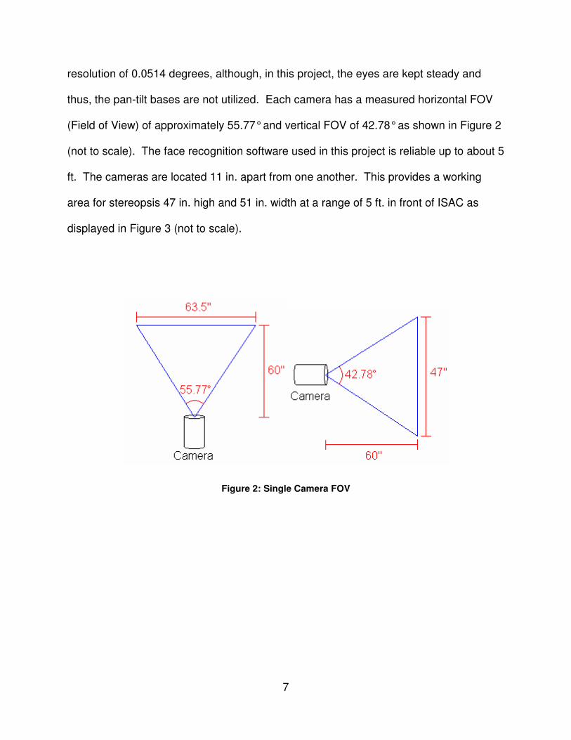
resolution of 0.0514 degrees, although, in this project, the eyes are kept steady and
thus, the pan-tilt bases are not utilized. Each camera has a measured horizontal FOV
(Field of View) of approximately 55.77° and vertical FOV of 42.78° as shown in Figure 2
(not to scale). The face recognition software used in this project is reliable up to about 5
ft. The cameras are located 11 in. apart from one another. This provides a working
area for stereopsis 47 in. high and 51 in. width at a range of 5 ft. in front of ISAC as
displayed in Figure 3 (not to scale).
Figure 2: Single Camera FOV

8
Figure 3: Stereopsis FOV
II.1.2. Arms
ISAC has two arms which are actuated by agonistic pairs of pneumatic air
muscles (McKibben Artificial Muscles). They are commonly known as Rubbertuators
since that was the commercial name for the McKibben actuators that were
manufactured by Bridgestone in the 1980s [44]. (Figure 4)
Figure 4: Rubbertuator

9
The concept behind a Rubbertuator is simple; it is a rubber tube surrounded by a
flexible fabric mesh that encloses a constant volume. When the muscle is pressurized it
expands. The mesh, holding the volume constant, causes the tube to contract. It
thereby converts radial force into a contraction force when filled with pressurized air.
Rubbertuators can only exert contractual force; therefore Rubbertuators are generally
used in antagonistic pairs to allow for a restoring force to exist.
Rubbertuators have qualities that make them good actuators for a humanoid
robot designed to interact with people. They are not rigid, they are compliant. In other
words, they give a bit when an opposing force is applied, even at maximum contraction.
Mechanical compliance is necessary for a robot that operates in the vicinity of
untrained, or lightly trained, human operators. Rubbertuators have the largest strength-
to-weight among actuators on the human scale. Once filled with air they can hold the
position indefinitely (within the limits of air loss) without the application of continuous
power.
One problem with Rubbertuators is that they are inaccurate compared to many
electric motor actuators. That is, the uncertainty in expected output given a known
input is large by comparison. This characteristic is caused, in part, by changes in the
flexibility of the rubber due to changes in temperature and humidity. Interestingly, this
characteristic is analogous to the effect of temperature on biological muscles [21] and to
the idea that humans can perform approximate motion with no visual feedback and
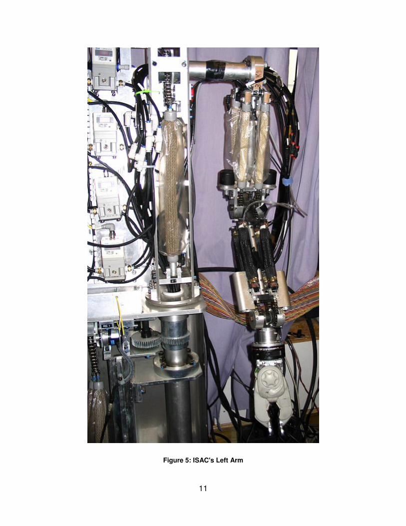
reach an approximate locaiton. Each of ISAC’s arms has 12 Rubbertuators paired to
work antagonistically on a manipulator chain with 6 degrees of freedom. Figure 5,

10
below, shows ISAC’s left arm. The older, beige Rubbertuators made by Bridgestone [1]
and the newer black ones, made by Shadow Robotics [29] are clearly visible.
11
Figure 5: ISAC's Left Arm

12
ISAC’s joints are typically numbered from 0 to 5 starting at his trunk and working out
toward the end effector. Angle 0 corresponds to his entire arm rotating, at the shoulder,
about the Z axis. This joint is controlled by a single pair of pneumatic muscles. Angle 1
is the shoulder joint that rotates the arm about an axis parallel to the Y axis. This angle
too is controlled by a pair of pneumatic muscles. Angle 2 refers to the elbow joint which
lifts the forearm about an axis parallel to the Y axis. Angle 3 rotates the forearm and
wrist about an axis parallel to the forearm. Angle 4 controls the pitch of the hand.
Angle 5 controls the roll of the hand. The construction of ISAC is a bit complex in that
Angles 2 and 3 are controlled by the same set of 4 air muscles. Angles 4 and 5 are also
controlled by a single set of 4 air muscles. Each set is arranged in a square. Figure 6
displays this arrangement.
Figure 6: 2 Pair Muscles Configuration

13
If the elbow joint is taken as an example, ISAC can lift up his forearm but also rotate it.
This varied action is accomplished using a universal joint in conjunction with the 4
muscles set. The combination is show, below, in FIGURE X. In reference to Figure 6,
the forearm can be lifted by contracting muscles 2 & 4 and relaxing muscles 1 & 3.
Clockwise rotation of the forearm can be achieved by contracting muscles 2 & 3 and
relaxing muscles 1 & 4.
Figure 7: Universal Elbow/Wrist Joint

14
The Rubbertuator’s disadvantages are many. Their performance variability due to
temperature and humidity, combined with their compliance, can make them difficult to
control accurately in a complex system. Despite their good strength to weight ratio, the
fact that they are powered by compressed air and rubber imposes severe limits on the
weight they can move. Lastly, Rubbertuators are, for the most part, unsuitable for
mobile robots due to their reliance on compressed air. The associated equipment is too
large to be attached to a small mobile robot in a practical way.
The compressed air that powers a Rubbertuator is provided by a compressor
tank that maintains a constant pressure. The air is fed through a a filter to clean and a
cooler to minimize the temperature variance of the muscles. The air is then fed to SMC
ITV2050-312CN4 Electro-Pneumatic Regulator valves [30], one per muscle, which
regulates how much air will be provided to the actual Rubbertuator. The valves, when
supplied with an input voltage from 0 to 5 volts will respond by allowing a proportional
amount of air pressure to be passed on to the muscles. When a lower voltage is
supplied, than was previously, the current air is exhausted out a port in the back of the
regulator until a satisfactory pressure is obtained. An array of these valves is mounted
on ISAC’s chest and back. His chest, covered in valves, can be seen in Figure 8 below.

15
Figure 8: Regulator Valve Array

16
The valves are controlled by 3 MOTENC-Lite controller cards [40] which sit in a
Windows 2000 based PC (Personal Computer). The controller cards allow simple
control of the valves and are described below in section II.1.3.
ISAC has encoders at every joint that provide feedback to the system. Joints
with a single axis of rotation interface with a single encoder. The universal joints,
located at the elbow and wrist, have 2 axes of rotation and, therefore, require 2
encoders. The set of encoders on the universal joints report the angular offset of both
the left and right side of the joint which are each controlled by a conjugate pair of
Rubbertuators. These angles can then be used to calculate the final angle of rotation
on both axes. The encoders on ISAC are either SUMTAK [37] or Epson-Seiko [7] rotary
encoders. In Figure 9, a SUMTAK is on the left and an Epson-Seiko is on the right.
The encoders rotate with an angular resolution of 0.345 degrees. If they are properly
initialized, the instantaneous angle of each joint can be monitored within the resolution
listed above.

17
Figure 9: Encoders
Unfortunately, these encoders are obsolete; they are out of production and very little
information is available on them. All rotary encoders, however, work in a similar way by
generating electrical pulses as a shaft rotates. Two signals, which are out of phase, are
constantly sent out while rotation is present. The signals consist of pulses which can be
counted to calculate how much rotation has occurred. By looking at which signal is
“ahead,” due to their difference in phase, one can tell which direction the rotation is in.
The encoders are read by the same MOTENC-Lite controller cards as control the
valves.

18
II.1.3. Controllers
ISAC’s encoders are read by, and his valves are controlled by, Vital Systems
MOTENC-Lite controller cards shown below in Figure 10.
Figure 10: MOTENC-Lite: PCI Board (pn 7541 & 7544)
These cards interface with a PC through the standard PCI (Peripheral Component
Interconnect) bus and use drivers written by Vital Systems. They are designed so that
several cards can be used in the same system. This is done by assigning each card a
unique identifier via jumpers on the board itself. ISAC’s control system has three of
these cards to control his 24 muscles and read his 12 encoders. Large ribbon cables

19
extend from each card and run to DAC/ADC/Encoder Termination Boards (pn 7525)
shown below in Figure 11 [41].
Figure 11: DAC/ADC/Encoder Termination Board for MOTENC-Lite (pn 7525)
The black terminal blocks on the short edges of the Termination Board are ADC (analog
to digital converter) and DAC (digital to analog converter) blocks. They connect to the
control lines of the valves to read from them and write to them. The larger blue terminal
blocks on the long edges are connections specifically designed to read from encoders.
As the image shows, four encoders can be read by single card so the three cards
support ISAC’s twelve encoders. It is a bit harder to see, but each board is capable of
supporting eight valves which, again, is in perfect harmony with ISAC’s 24 air muscles.

20
II.2. OpenCV
Much of the computer vision software in the system is built on top of Intel’s
OpenCV (Open Computer Vision) Library [15, 27, 34]. OpenCV, in its simplest form, is
a collection of functions that facilitate computer vision related programming. The
efficiency of OpenCV depends on the presence of Intel’s IPP (Integrated Performance
Primitives) [13] which are a commercial library of functions that perform routines related
to multimedia processing and multi-core functionality at the assembly and machine code
level. IPP is designed only to work with Intel microprocessors. While the software
developed for this thesis does not use IPP due to the associated cost, it could easily be
installed to increase the performance of the system’s computer vision components.
OpenCV is, in actuality, not just a random collection of functions but is, instead, a
well organized set of tools that a programmer can use to quickly implement solutions to
computer vision problems. All computer vision functions in OpenCV are designed to
operate on the IplImage structure, also defined in OpenCV. The typedef for an
IplImage is shown in Figure 12.

21
typedef struct _IplImage
{
int nSize; /* sizeof(IplImage) */
int ID; /* version (=0)*/
int nChannels; /* Most of OpenCV functions support 1,2,3 or 4
channels */
int alphaChannel; /* ignored by OpenCV */
int depth; /* pixel depth in bits: IPL_DEPTH_8U,
IPL_DEPTH_8S, IPL_DEPTH_16U,
IPL_DEPTH_16S, IPL_DEPTH_32S, IPL_DEPTH_32F
and IPL_DEPTH_64F are supported */
char colorModel[4]; /* ignored by OpenCV */
char channelSeq[4]; /* ditto */
int dataOrder; /* 0 - interleaved color channels, 1 - separate
color channels. cvCreateImage can only
create interleaved images */
int origin; /* 0 - top-left origin,
1 - bottom-left origin (Windows bitmaps
style) */
int align; /* Alignment of image rows (4 or 8). OpenCV
ignores it and uses widthStep instead */
int width; /* image width in pixels */
int height; /* image height in pixels */
struct _IplROI *roi;/* image ROI. when it is not NULL, this
specifies image region to process */
struct _IplImage *maskROI; /* must be NULL in OpenCV */
void *imageId; /* ditto */
struct _IplTileInfo *tileInfo;/* ditto */
int imageSize; /* image data size in bytes
(=image->height*image->widthStep
in case of interleaved data)*/
char *imageData; /* pointer to aligned image data */
int widthStep; /* size of aligned image row in bytes */
int BorderMode[4]; /* border completion mode, …*/
int BorderConst[4]; /* … ignored by OpenCV */
char *imageDataOrigin; /* pointer to a very origin of image data
(not necessarily aligned) -
it is needed for correct image
deallocation */
}
IplImage;
Figure 12: IplImage Structure (condensed) [31]
The IplImage structure was designed by Intel for their Intel Image Processing Library
(IPL). The Intel IPL is no longer a supported product [14] and has since been integrated
into the Intel Performance Primitives product. OpenCV allows for many complex image

22
operations to be done via a single, one line, functions. In addition to premade functions
OpenCV also comes bundled with HighGUI [32] which allows a programmer to setup a
simple GUI (Graphical User Interface), for testing, extremely quickly. Details on the
specific, usage of the OpenCV library are discussed further in the Vision System section
III.1.
II.3. CalTech Image Calibration Toolbox for Matlab
Computer Vision is used in a wide variety of applications and can be built upon
anything from a $10 web-cam with an old laptop to setups that costs many thousands of
dollars with state-of-the-art equipment. The precision of any computer vision system
depends on accurate knowledge of the projective transformations imposed by the
cameras. Those transformations depend on the camera’s focal length, sensor size and
density, sensor noise characteristics, optical distortion including the point-spread
function and radial position deviation, etc. Some of these parameters are published by
the camera manufacturer, particularly for higher end equipment. However, information
on some of the more subtle camera parameters can be hidden even for the expensive
components. For an amateur, with a web-cam that was pulled out of an old box of
electronics, it is very possible that none of this information is readily available. That is
where the CalTech Image Calibration Toolbox [3] comes in handy.
Dr. Jean-Yves Bouguet [4] of the Computer Vision Research Group at CalTech
saw this problem and designed a tool to help overcome it. The Calibration Toolbox
works in the following way. It takes, as input, a set of images with a test sheet in
different orientations. This test sheet is a checkerboard pattern with identical squares of

23
known sizes. The software uses its a priori knowledge of the checkerboard pattern to
analyze the set of images distorted by the camera. The analysis returns estimates of
the parameters which are used to estimate the projective transformations. This allows
the user to then design computer vision software optimized for the camera’s unique
parameters. For this research, the camera parameters were estimated with the
CalTech software.
II.4. Previously Developed Code
To expedite creation of the system, code that had been previously developed by
other students was used. For the most part, that code included low level drivers and
interfaces for components like the cameras and arm control. Each instance of borrowed
code is described below.
II.4.1. PXC Drivers
ISAC’s cameras provide data to a PC in the form of a stream of video frames that
are delivered via Phase 1 Technology PS-99SU Frame Grabbers. Software drivers are
necessary to interface with these frame grabbers. Code, called PCX, that makes the
frames accessible to C++ programs was preexisting in the lab although it is unclear who
wrote it.
24
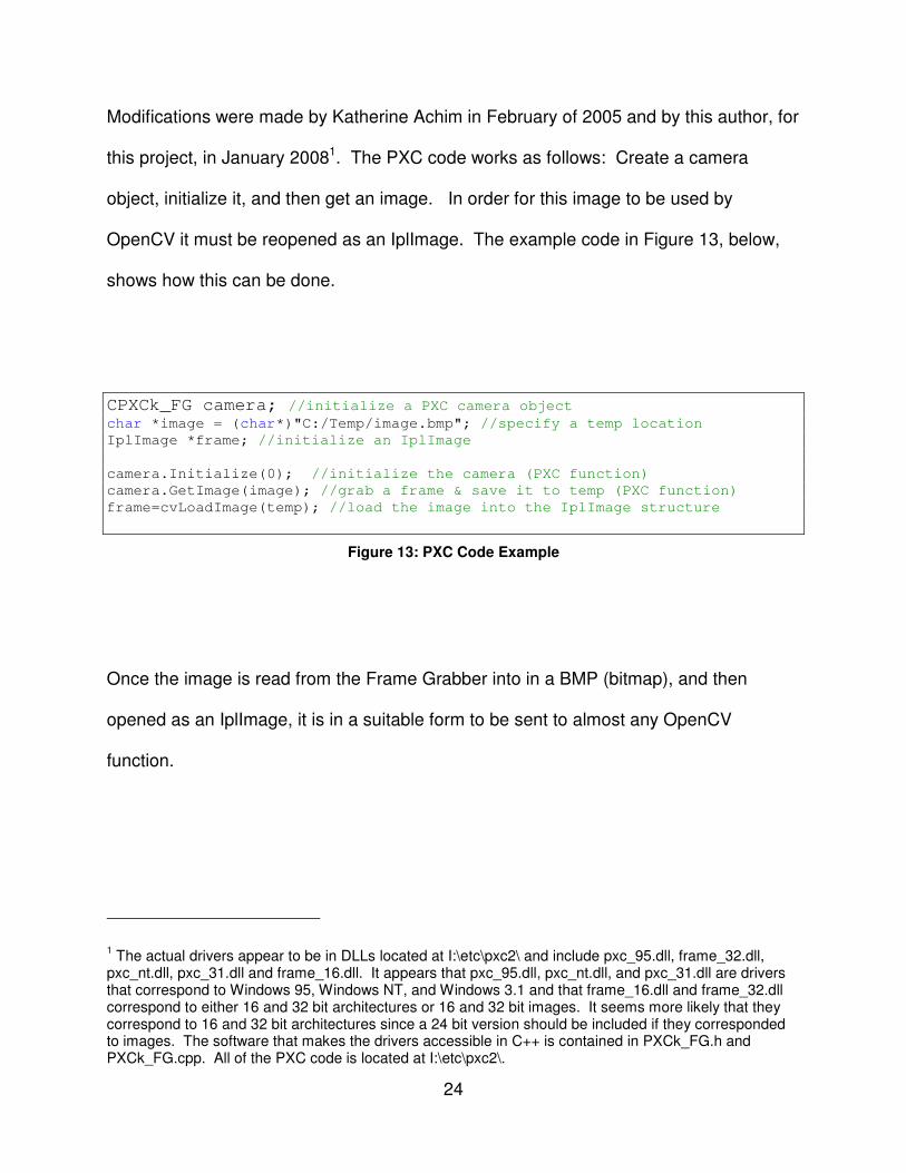
Modifications were made by Katherine Achim in February of 2005 and by this author, for
this project, in January 20081. The PXC code works as follows: Create a camera
object, initialize it, and then get an image. In order for this image to be used by
OpenCV it must be reopened as an IplImage. The example code in Figure 13, below,
shows how this can be done.
CPXCk_FG camera; //initialize a PXC camera object char *image = (char*)"C:/Temp/image.bmp"; //specify a temp location
IplImage *frame; //initialize an IplImage
camera.Initialize(0); //initialize the camera (PXC function)
camera.GetImage(image); //grab a frame & save it to temp (PXC function)
frame=cvLoadImage(temp); //load the image into the IplImage structure
Figure 13: PXC Code Example
Once the image is read from the Frame Grabber into in a BMP (bitmap), and then
opened as an IplImage, it is in a suitable form to be sent to almost any OpenCV
function.
1 The actual drivers appear to be in DLLs located at I:\etc\pxc2\ and include pxc_95.dll, frame_32.dll,
pxc_nt.dll, pxc_31.dll and frame_16.dll. It appears that pxc_95.dll, pxc_nt.dll, and pxc_31.dll are drivers that correspond to Windows 95, Windows NT, and Windows 3.1 and that frame_16.dll and frame_32.dll correspond to either 16 and 32 bit architectures or 16 and 32 bit images. It seems more likely that they correspond to 16 and 32 bit architectures since a 24 bit version should be included if they corresponded to images. The software that makes the drivers accessible in C++ is contained in PXCk_FG.h and PXCk_FG.cpp. All of the PXC code is located at I:\etc\pxc2\.

25
II.4.2. Connected Components Extraction
In Computer Vision it is often necessary that objects be found in a scene and
then isolated (segmented). This system uses color to segment and track objects.
Segmentation is performed via hue filtering. To do this an image mask is used.2 Any
pixels that are, say, green, are marked as foreground in the mask all others are marked
background. This mask has is black wherever there is background and white wherever
there is foreground. Figure 14, below, shows an example of a frame, on the left, and its
associated mask, on the right, when a green hue is the target. This particular image
also displays the results of a morphological erode and dilate. Usage of such a function
is described further in section III.1.1.
Figure 14: Green Hue Mask Example
2 An image mask is a binary image with the same dimensions as the image that is being masked. The
polarity of a pixel in the mask typically indicates that the corresponding pixel in the image is of interest or not. For example a one might indicate that the pixel has a specific feature, zero indicates that it does not.

26
Multiple objects are distinguished using Connected Component labeling. A Connected
Component is simply a set of foreground pixels that are all touching one another. If
there is a break between foreground pixels, by background, then those pixels are
deemed to be part of separate connected components. A previously written program for
connected component labeling, written by Tom Billings and Jack Noble, was used to
accomplish this task. This author made minor modifications to it removing some hard
coded values for image height and width and replacing them with values gleaned from
the image structure itself. From the list of connected components, returned by the
program, the largest was selected as the object of interest.
II.4.3. New Neural Network / PID Controller
The first part of this project involved the tracking of an object in 3D and second
revolves around filtering out its generalized motion. The third, and final, objective is to
cause ISAC’s arms to move so as to mimic the motion of the object. Several controllers
have been created that cause ISAC to move an arm to a specific 3D location in its
workspace. One of these is a combination Neural Network [42] and PID controller.
That controller was modified by this investigator for this project. The Neural Network
portion of the controller works by training ISAC to associate muscle pressures and 3D
locations of the end-effector (hand). The PID portion of the controller moves the arm to
minimize the distance between the desired location and the actual location as computed
from the outputs of the joint position encoders. The controller is fast relative to the
speed of arm motion so the resultant motion is fairly smooth. The composite controller
initiates the neural network which moves the arm to a rough approximation of the target

27
location within a time interval that can be set by the designer. A common interval might
be on the order of 500ms. Then it initiates the PID controller to make final, precision,
adjustments. In this system, only the Neural Network is considered, the PID controller
has been disabled. This is primarily for safety. The system is designed to interact with
human being. Since the Neural Network is entirely open-loop if it encounters an
obstacle, such as a person, it will not continue to try to work through it [38]. A PID
controller, on the other hand, is closed-loop and thus it will notice that it is not at its
desired location and will continue to instruct the manipulator to go there possibly
causing injury to the human obstacle. Furthermore, the Neural Network based
controller more closely mirrors the muscle memory operations of a human. If an actual
human were to repeat an observed gesture, such as a wave, the attempt would be
primarily from muscle memory with little, if any, visual feedback being utilized place.
The Neural Network used in this controller is not extraordinary in any way and
follows from the standard model. It is known, more specifically, as a Back-Propagation
Neural Network with a Generalized Delta Rule. This is an excellent choice for the
system due to the non-linearity of the McKibben muscles caused by hysterysis which
derives from the friction of the woven membrane on the outside of the muscles.
Because of this hysterysis two separate Neural Networks have been created. One
applies only to forward motion, the other only to backward motion.

28
Figure 15: Neural Network
As is shown in Figure 15, the input and output layers of the Neural Network each
consist of a single neuron. The middle layer consists of ten neurons. The system was
trained with a 10,000 epochs, between 150 and 250 data points, a learning rate of
0.001, and 1,000,000 iterations. This gave rise to errors of only a few degrees which
was deemed suitable for this system [8].

29
CHAPTER III
THE COMPLETE SYSTEM
III. THE COMPLETE SYSTEM
The goal of this project was to create a system by which ISAC would be able to
see a person making an arm gesture and then repeat it (given the limitations imposed
by ISAC’s workspace). Figure 16 is a list of the tasks that must be accomplished for
ISAC to achieve the goal.

30
1. Initialize ISAC’s cameras
2. Retrieve a frame from ISAC’s left and right cameras
3. Detect the object of interest in both the left and right frame
4. Calculate the 3D location of the objects of interest
5. Save the 3D location along with its relative timestamp
6. Repeat steps 2 – 5 until the gesture is complete. A list of 3D coordinates is now
saved
7. Filter the list of 3D points to eliminate artifacts and noise
8. Compress the list of 3D points down to as few points as are necessary to capture
the general motion of the object of interest
9. Scale the list to fit within ISAC’s workspace
10. Calculate Joint Angles via Inverse Kinematics
11. Upload the list of joint angles to ISAC’s arm control system (located on a
separate PC from the vision control system)
12. Iterate through the list of joint angles and have ISAC move his arm to the
associated location
Figure 16: Solution Outline
The rest of this section provides details of the implementation (e.g., the routines and
parameters used) and a description how it works.

31
III.1. Vision Subsystem
ISAC’s vision system operates from the PC in the Cognitive Robotics Lab named
Sally, which runs Windows XP. Two Sony XC-999 Cameras, each mounted on its own
Directed Perception pan-tilt unit, connect to twin Phase 1 Technology PS-99SU Frame
Grabbers which in turn plug into PCI capture cards in the computer. Frames are
retrieved using the PXC software, described in section II.4.1, and are made available to
the rest of the program which is described, in detail, below.3
III.1.1. Object Detection
Object detection is performed on a per-frame per-object basis. That is to say, in
order for the system to track two objects using two cameras, the object detection routine
is run four times. The function is show below in Figure 17.
void detectObject(IplImage* img, CvTarget *tar, int low, int high)
{
//Temporary Images
IplImage* hsv = cvCreateImage(cvGetSize(img), 8, 3);
IplImage* hue = cvCreateImage(cvGetSize(img), 8, 1);
IplImage* sat = cvCreateImage(cvGetSize(img), 8, 1);
IplImage* val = cvCreateImage(cvGetSize(img), 8, 1);
IplImage* maskH = cvCreateImage(cvGetSize(img), 8, 1);
//kernel for use with erode/dilate
IplConvKernel * selem =
cvCreateStructuringElementEx(3,3,1,1,CV_SHAPE_RECT);
//Extract Hue/Sat/Val from BGR Image
3 The code examples have been cleaned up, condensed, and formatted so that they fit cleanly in this document. However, none of the functionality has been changed. Comments have simply been rearranged or taken out. When necessary, lengthy code has been replaced with more concise pseudo-code.

32
cvCvtColor(img, hsv, CV_BGR2HSV); //convert from BGR to HSV
cvSplit (hsv, hue, sat, val, 0); //extract hue/sat/val channels
//Filter by Hue
cvInRangeS(hue, cvScalar(low), cvScalar(high), maskH);
//Erode/Dilate maskH to eliminate noise
cvErode(maskH,maskH,selem,3);
cvDilate(maskH, maskH, selem, 3);
//Find the largest positive object
getConnectedComps(maskH,Comps);
if (comptot != 0)
{
//find largest component
maxcomp = 0;
maxarea = Comps[0]->area;
for (int j = 0; j < comptot; j++)
{
if (Comps[j]->area > maxarea)
{
maxarea = Comps[j]->area;
maxcomp = j;
}
}
//get center
tar->x = Comps[maxcomp]->rect.x + Comps[maxcomp]->
rect.width/2;
tar->y = Comps[maxcomp]->rect.y + Comps[maxcomp]->
rect.height/2;
//get radius
if (Comps[maxcomp]->rect.width > Comps[maxcomp]-
>rect.height) tar->r = Comps[maxcomp]->rect.width/2;
else tar->r = Comps[maxcomp]->rect.height/2;
}
//Release Images
cvReleaseImage(&hsv);
cvReleaseImage(&hue);
cvReleaseImage(&sat);
cvReleaseImage(&val);
cvReleaseImage(&maskH);
}
Figure 17: detectObject code (condensed)
33
The function is called detectObject. It takes a pointer to an IplImage (img), a lower
hue bound (low) and an upper hue bound (high) as inputs. A pointer to a CvTarget
object (tar) is used as an output. The process begins by converting the image from
the 32-bit per pixel, BGR (Blue Green Red) representation provided by the frame
grabber into a 32-bit HSV (Hue Saturation Value) representation. The HSV image,
which is a single three-band image, is then split into three, 8-bit, one-band images: hue,
saturation, and value. The saturation and value bands are not used. The hue image is
then segmented for a specific range of hues that have been computed from earlier
images of the target object. A black and white mask is created by a raster scan
thresholding of the hue image. If the hue value of a pixel is between the low bound and
the high bound (the extrema of the specified hue range) then the corresponding pixel in
the mask image is colored white. Otherwise it is colored black. The mask image is then
eroded and dilated with a 3×3 square structuring element [9, 10]. The erosion gets rid
of noise by eliminating any small instances of foreground (white) in the mask. The
dilation then returns the foreground areas that survived the erosion back to their original
sizes.4 The mask is then analyzed by the getConnectedComps function (cf. section
II.4.2) which returns a list connected foreground components. This list is searched for
the largest component. Its radius and center point are then found and stored in the tar
variable. The tar variable is returned with the location and size of the largest object of
a particular color. Lastly the image variables are released to free up that memory.
4 Erosion followed by dilation with the same structuring element is called opening.

34
III.1.2. Haar Face Detection
To effectively find the location of the user’s face, a detection algorithm that takes
advantage of Haar-like features was used [12, 39]. These Haar-like features allow for
classification, of an object of interest, to be described by its light and dark regions and
their proximity to one another. Figure 18 displays the current, extended, set of Haar-like
features.
Figure 18: Extended Set of Haar-like Features [17]
Each one of the features listed above can be applied to an object of interest. Take a
human face, for example. Edge feature (b) would be applied to the forehead/eye socket
region because the eye sockets cause that area of the face to be darker then the
forehead which reflects light well. Line feature (a) would be inverted and then applied to
the eyes and nose because, again, the eye sockets cause the left and right regions of

35
the middle face to be darker then the center which contains the bridge of the nose. It is
not required that a developer calculates and inputs all of these features by hand.
OpenCV comes bundled with software designed to analyze a set of test images that
contain both positive and negative samples. These test images, for a successful
outcome, should number in the thousands. If this many, unique, images cannot be
acquired, functionality also exists to distort a smaller set of images to artificially create
more positives. Once this analysis is complete an XML file, known as a cascade file, is
created that contains all of the necessary feature information. This cascade file can
then be applied to any project. This entire procedure is detailed in Naotoshi Seo’s
haartraining Guide [19]. Particularly in the case of face detection, this functionally takes
place behind the scenes and a predefined cascade prepared for faces already exists
within OpenCV. This author has selected the cascade file
haarcascade_frontalface_alt2.xml. When using the OpenCV
implementation for face detection, it is not necessary that a developer be familiar with
these workings. The function that this author has used is derived largely from the
facedetect.cpp example provided with the OpenCV package. The, modified,
function, along with several required global variables, is shown in Figure 19.

36
const char* cascade_name = "haarcascade_frontalface_alt2.xml";
static CvHaarClassifierCascade* cascade =
(CvHaarClassifierCascade*)cvLoad( cascade_name, 0, 0, 0 );
static CvMemStorage* storage = cvCreateMemStorage(0);
void haarFaceDetect(IplImage* img, CvTarget *tar)
{
//initialize variables
int radius;
int i;
double scale = 1.3;
IplImage* gray = cvCreateImage( cvSize(img->width,img-
>height), 8, 1 );
IplImage* small_img = cvCreateImage( cvSize( cvRound
(img->width/scale), cvRound (img->height/scale)), 8, 1 );
//convert image to a small grayscale version
cvCvtColor( img, gray, CV_BGR2GRAY );
cvResize( gray, small_img, CV_INTER_LINEAR );
cvEqualizeHist( small_img, small_img );
cvClearMemStorage( storage );
//if a cascade has been setup, find the faces
if( cascade )
{
CvSeq* faces = cvHaarDetectObjects( small_img, cascade,
storage, 1.1, 2, 0/*CV_HAAR_DO_CANNY_PRUNING*/,
cvSize(30, 30) );
tar->r = 0; //initialize the target radius to 0
//cycle through detected faces to find the largest
for( i = 0; i < (faces ? faces->total : 0); i++ )
{
CvRect* r = (CvRect*)cvGetSeqElem( faces, i );
radius = cvRound((r->width + r->height)*0.25*scale);
//if new r (face) > old r (face), save loc to tar
if (radius > tar->r)
{
tar->r = radius;
tar->x = cvRound((r->x + r->width*0.5)*scale);
tar->y = cvRound((r->y + r->height*0.5)*scale);
}
}
}
//release images
cvReleaseImage( &gray );
cvReleaseImage( &small_img );
}
Figure 19: haarFaceDetect code
37
The global declarations, shown above the haarFaceDetect function point to a
predefined Haar cascade file, initialize the cascade based on the cascade file, and
setup memory storage for use in the function, respectively. Within the
haarFaceDetect function several variables including holders for a gray version of
the input image and a small version of grayscale image are declared. Then the image
is converted to grayscale and scaled down. Now is where the real Haar detection
begins. If a cascade has been initialized then a CvSeq (or sequence) is created to hold
face matches. The sequence is then iterated through and the largest face object is
found and recorded into the tar variable which represents the size and location of the
largest face in the image. This variable also acts as the function’s output since it was
passed in by reference. Lastly the newly created images are release to avoid
congestion in memory.
III.1.3. Object Tracking
Section III.1.1 described how a single object was located in a single frame. This
section attempts to describe how the detectObject function is used to keep track of
the location of the object over a period of time. A condensed version of the main loop in
the program is show below in Figure 20.

38
for(;;) //loop forever
{
start = GetTime();
//proceed if a frame is successfully retrieved
if(cameraL.GetImage(tempL) && cameraR.GetImage(tempR))
{
frameL=cvLoadImage(tempL); //load the left frame
frameR=cvLoadImage(tempR); //load the right frame
}
else
{
//error if we can't get a frame from the camera
fprintf(stderr, "ERROR: Could not retrieve frames from
Cameras\n");
break;
}
//haar detect/draw face
haarFaceDetect(frameL, &lf);
haarFaceDetect(frameR, &rf);
//detect object 1 (light blue bean bag)
detectObject(frameL, &l1, HUE_LIGHT_BLUE_BAG[0],
HUE_LIGHT_BLUE_BAG[1]); //detect object 1 in our Left Image
detectObject(frameR, &r1, HUE_LIGHT_BLUE_BAG[0],
HUE_LIGHT_BLUE_BAG[1]); //detect object 1 in our Right Image
//detect object 2 (green lego lid)
detectObject(frameL, &l2, HUE_BIG_GREEN_BALL[0],
HUE_BIG_GREEN_BALL[1]); // detect object 2 in our Left Image
detectObject(frameR, &r2, HUE_BIG_GREEN_BALL[0],
HUE_BIG_GREEN_BALL[1]); //detect object 2 in our Right Image
//draw object 1 targets onto the original image
drawTarget(frameL, l1, 0);
drawTarget(frameR, r1, 0);
//draw object 2 targets onto the original image
drawTarget(frameL, l2, 7);
drawTarget(frameR, r2, 7);
//calculate relative XYZ depth
calculateXYZ(&obj1loc, l1, r1);
calculateXYZ(&obj2loc, l2, r2);
//print the coordinates to a text file
fprintf(coordsfile,"%d,,%d,%d,%d,%d,%f,%f,%f,,%d,%d,%d,%d,%f,%f,%
f\n",counter,l1.x,l1.y,r1.x,r1.y,obj1loc.x,obj1loc.y,obj1loc.z,l2
.x,l2.y,r2.x,r2.y,obj2loc.x,obj2loc.y,obj2loc.z);
//display images to the user
cvShowImage("Tracker Left", frameL); //show the left frame

39
cvShowImage("Tracker Right", frameR); //show the right frame
//give the user a chance to break the loop by hitting any key
if(cvWaitKey( 10 ) >= 0) break;
counter++; //increment the time counter
//ensure loop is 400ms each time
stop = GetTime();
total = stop - start;
if (total < 400) Sleep(400-total);
}
Figure 20: Main Vision Loop code (condensed)
The loop begins by retrieving a frame from both the left and right cameras. If the frames
cannot be retrieved, then the program errors out. Each frame must then be loaded into
an IplImage structure so that it is in a form suitable for the OpenCV code to operate on.
The haarFaceDetect function searches for human faces based on Haar-like
identifiers. This function is described in greater detail in section III.1.2. The
detectObject function, described in section III.1.1, is then run 4 times to cover
objects 1 & 2 in both the left and right cameras. As mentioned in section III.1.1, the
location and radius of the object is returned in a cvTarget variable. l1, l2, r1, r2,
lf, & rf are all cvTarget variables designed to store the location and size of each
object in both the left and right frames5. The targets are then drawn onto the original
frames via the drawTarget function described in section III.1.4. Next, the 3D location
5 It is important to note that in the current implementation with the current code: object 1 refers to the teal
bean bag and is intended to be held in the user’s left hand. Object 2 refers to the green Lego lid and is
intended to be held in the user’s right hand.

40
object 1, object 2, and the face are calculated in the calculateXYZ function
described in section III.1.4. Then, both the 2D and 3D location information is saved into
a comma delimited text file for processing later in the program. Both frames, with the
targets drawn on, are then displayed to the user via the cvShowImage function. The
user is then given an opportunity to break out of this loop by pressing a key when the
gesture recording is complete. Lastly, a time counter is updated so that the relative time
at which a point has been recorded can be preserved.
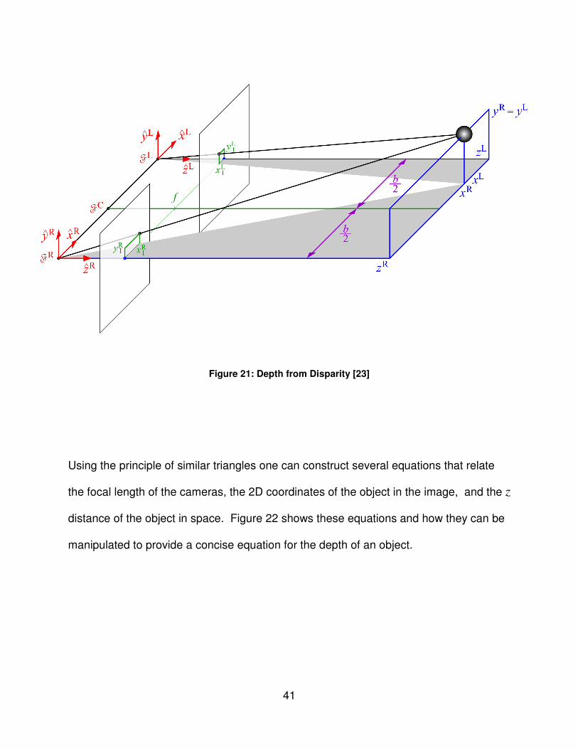
III.1.4. Calculating 3D Locations
Using a method known as Depth from Disparity a 3D (xyz) location can be
calculated from two 2D (xy) points so long as the two 2D points meet certain
requirements. For the method used here, the 2D points must come from cameras that
are coplanar. Certain information about the cameras focal points and their distance
from one another must be known as well. Depth from Disparity works using the
principle of similar triangles. Figure 21, below, illustrates this principle.
41
Figure 21: Depth from Disparity [23]
Using the principle of similar triangles one can construct several equations that relate
the focal length of the cameras, the 2D coordinates of the object in the image, and the z
distance of the object in space. Figure 22 shows these equations and how they can be
manipulated to provide a concise equation for the depth of an object.

42
Figure 22: Depth from Disparity equations [23]
Equation 3 demonstrates that z in both the left and right frames are equal, as it should
be and show how this can be calculated from the x location of the object in the left and
right frames along with the focal length and baseline (distance between the cameras).
The focal length, f , and baseline, b, will be in some real units such as millimeters. The
x values, by default will be in pixels. In order for the equation to yield a z that is also in
millimeters the x values must be converted from pixels into millimeters which can be
done based on the parameters of the camera itself. The camera will have a CCD of a
certain size and will produce images of a certain resolution. These two values can be

43
used to calculate how many pixels per millimeter the camera produces. Equations 5 &
7 show how the real y and x coordinates can be calculated based on the z coordinate
that was calculated along with the focal length and original y (or x) coordinate on the
image plane.
The above equations were used to create the calculateXYZ function which is
show below in Figure 23.
void calculateXYZ(CvPoint3D32f *objloc, CvPoint left, CvPoint right)
{
double f = 15262.5; //focal length: 305.25 millimeters (50
//px/mm) = 15262.5 px
double b = 14000; //base: millimeters (50 px/mm) = 14000 px
double sigma = 50; //pixels per mm
//get pixel coords
xri = (double)right.x; xli = (double)left.x;
yri = (double)right.y; yli = (double)left.y;
//find z in weird units
z=f*b/((double)xli-(double)xri);
//calculate real y and x values in weird units
yr=yri*z/f; yl=yli*z/f;
xr=xri*z/f; xl=xli*z/f;
//average x & y
x=(xr+xl)/2; y=(yl+yr)/2;
//write the values into the objloc to be returned
objloc->x=x; objloc->y=y; objloc->z=z;
}
Figure 23: calcuateXYZ code (condensed)
The function starts by defining the focal length, f, and baseline, b, will which have been
found via the CalTech Image Calibration Toolbox for Matlab. This Toolbox is described

44
in further detail in section II.3. Next the pixel coordinates are extracted from the CvPoint
objects and then used, along with f and b to find the z. As mentioned before, the X & Y
images coordinates must be translated into real units in order to get real units out.
However, the relative motion of the objects, not their absolute positions, is the primary
concern. Some math was thereby avoided in doing this conversion. The 3D points end
up in “unknown” units. This, however, is not a problem as any units would have to be
rescaled to fit within ISAC’s workspace. The next step is to calculate the associated X
and Y locations in these unknown units. Since an X and Y location are found for both
the left and right images. They are averaged to come up with a single X and a single Y
value. The values are then saved to the output variable objloc. This procedure is
done for every single set of 2D image coordinates that are gathered by ISAC’s vision
system. As described in the vision section, the 2D coordinates along with a timestamp
and the newly calculated 3D coordinates are saved to a text file that can be filtered and
processed.
III.1.5. drawTargets Function
The drawTargets function is very simple and allows a circle with a dot in the
center to be drawn onto a frame taken, in this case, from ISAC’s cameras. The, short,
function is show below in.

45
void drawTarget(IplImage *img, CvTarget obj, int clr)
{
if (obj.x <= img->width && obj.y <= img->height && clr <
NUM_COLORS)
{
//draw a circle on the screen
cvCircle( img, obj, obj.r, COLORS[clr], 3, 8, 0 );
cvCircle( img, obj, 1, COLORS[clr], 3, 8, 0 );
}
}
Figure 24: drawTarget code (condensed)
The if statement in the function checks to make sure that the center point defined by the
cvTarget is in the image, and that clr, a numeric reference to a color defined by the
array COLORS is within its range. If both of these conditions are met, then 2 circles are
drawn on the screen. Both circles are at the location specified. However only the first
has the radius specified by the cvTarget. The second has a radius of 1 and performs
the function of drawing a dot in the center of the first.
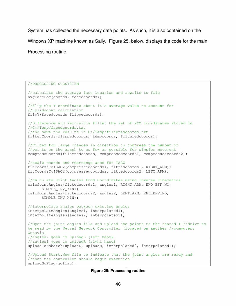
III.2. Processing Subsystem
The next large subsystem is Processing. It engages after the Vision System has
completed. That is to say, once a set of 2D points from both the left and right images
has been collected, they must be processed to convert them to a single set of 3D
locations (per object). This set of 3D locations must then be further filtered and
processed in order for it to be usable by ISAC’s control systems. The processing is
done in the same program as the Vision System operates and happens after the Vision
46
System has collected the necessary data points. As such, it is also contained on the
Windows XP machine known as Sally. Figure 25, below, displays the code for the main
Processing routine.
//PROCESSING SUBSYSTEM
//calculate the average face location and rewrite to file
avgFaceLoc(coords, facedcoords);
//flip the Y coordinate about it's average value to account for
//upsidedown calculation
flipY(facedcoords,flippedcoords);
//Difference and Recursivly filter the set of XYZ coordinates stored in
//C:/Temp/facedcoords.txt
//and save the results in C:/Temp/filteredcoords.txt
filterCoords(flippedcoords, tempcoords, filteredcoords);
//Filter for large changes in direction to compress the number of
//points on the graph to as few as possible for simpler movement
compressCoords(filteredcoords, compressedcoords1, compressedcoords2);
//scale coords and rearrange axes for ISAC
fitCoordsToISAC2(compressedcoords1, fittedcoords1, RIGHT_ARM);
fitCoordsToISAC2(compressedcoords2, fittedcoords2, LEFT_ARM);
//calculate Joint Angles from Coordinates using Inverse Kinematics
calcJointAngles(fittedcoords1, angles1, RIGHT_ARM, END_EFF_NO,
SIMPLE_INV_KIN);
calcJointAngles(fittedcoords2, angles2, LEFT_ARM, END_EFF_NO,
SIMPLE_INV_KIN);
//interpolate angles between existing angles
interpolateAngles(angles1, interpolated1);
interpolateAngles(angles2, interpolated2);
//Open the joint angles file and upload the points to the shared I //drive to
be read by the Neural Network Controller (located on another //computer:
Octavia)
//angles2 goes to uploadL (left hand)
//angles1 goes to uploadR (right hand)
uploadToNNbatch(uploadL, uploadR, interpolated2, interpolated1);
//Upload Start.Now file to indicate that the joint angles are ready and
//that the controller should begin execution
uploadGoFlag(goflag);
Figure 25: Processing routine

47
Processing begins by averaging the face’s location. The assumption is made that the
user will not move their body around as their gestures are being recorded. This is a
valid assumption since the user is asked to keep his, or her, head still during the
recording. Averaging of the face location allows for anomalies and frames in which no
face was detected to be discarded without adversely affecting the system.
avgFaceLoc is described in greater detail in section III.2.1. The flipY function,
described in section III.2.2, is then run to account for a disconnect between the
program’s logic and ISAC’s world frame. The coordinates are then filtered to eliminate
artifacts in the signals using the filterCoords function described in section III.2.1.
compressCoords is then run to reduce the number of points that describe the motion
to as few as possible. compressCoords is described in detail, in section III.2.4.
Once the coordinates have been compressed they must be fit to ISAC’s workspace.
This is done using the fitCoordsToISAC2 function described in section III.2.5. The
fitted coordinates represent locations that ISAC must reach to. In order for these
locations to be realized, the appropriate joint angles must be calculated.
calcJointAngles is responsible for this conversion and is described in section
III.2.6. Once the angles have been calculated, interpolateAngles (section III.2.7)
is run to fill in points between each change of position. These points are calculated in
such a way as to smooth the motion by creating intermediate angles. Finally, after all of
the angles have been prepared, the points are uploaded to the Controller so that it may
execute the motions have ISAC’s response can be realized. uploadToNNbatch is
described in detail in section III.2.7.

48
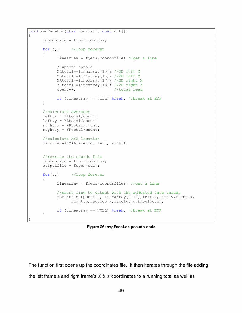
III.2.1. avgFaceLoc Function
While the Haar face detect function (section III.1.2) is fairly reliable it can never
be counted on to return a face location every frame and it cannot be depended on to be
without error. To overcome this problem the avgFaceLoc function has been
developed. This function, shown in Figure 26, simply analyzes all of the face locations
and, ignoring any blank entries, calculates the average location. It then rewrites that
average location to each entry.
49
void avgFaceLoc(char coords[], char out[])
{
coordsfile = fopen(coords);
for(;;) //loop forever
{
linearray = fgets(coordsfile) //get a line
//update totals
XLtotal+=linearray[15]; //2D left X
YLtotal+=linearray[16]; //2D left Y
XRtotal+=linearray[17]; //2D right X
YRtotal+=linearray[18]; //2D right Y
count++; //total read
if (linearray == NULL) break; //break at EOF
}
//calculate averages
left.x = XLtotal/count;
left.y = YLtotal/count;
right.x = XRtotal/count;
right.y = YRtotal/count;
//calculate XYZ location
calculateXYZ(&faceloc, left, right);
//rewrite the coords file
coordsfile = fopen(coords);
outputfile = fopen(out);
for(;;) //loop forever
{
linearray = fgets(coordsfile); //get a line
//print line to output with the adjusted face values
fprintf(outputfile, linearray[0-14],left.x,left.y,right.x,
right.y,faceloc.x,faceloc.y,faceloc.z);
if (linearray == NULL) break; //break at EOF
}
}
Figure 26: avgFaceLoc pseudo-code
The function first opens up the coordinates file. It then iterates through the file adding
the left frame’s and right frame’s X & Y coordinates to a running total as well as

50
incrementing a count variable which keeps a total of all lines read6. These values are
then used to compute averages. The 3D location of the average is then found. The file
is close and reopened and the lines are then written to the output file with the new
average face location in place of the original face locations.
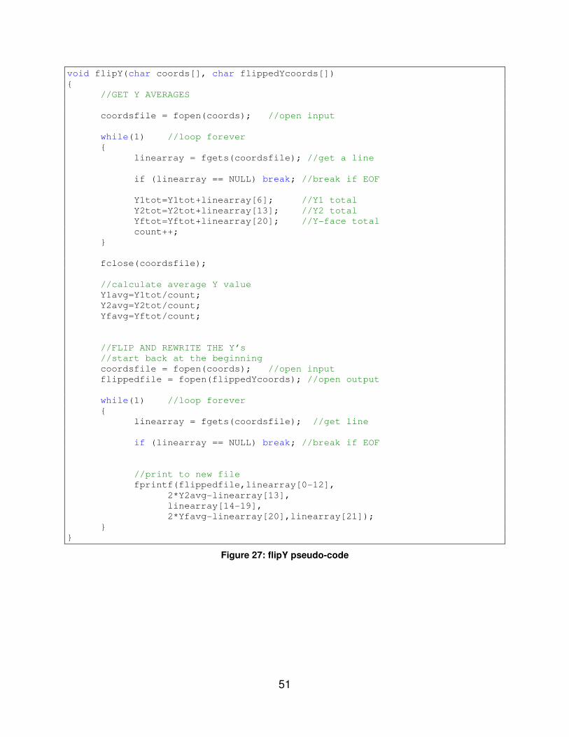
III.2.2. flipY Function
Due to a difference in the way ISAC’s world is perceived and the way the program was
originally written to run there is a discrepancy in the representation of the Y axis.
Rather then rewrite many parts of the program it was decided that a simpler solution
would be to write an intermediate function designed to simply flip the Y motion about its
average. The function finds the average for Y1, Y2 , Y-face, and then rewrites these
variables flipped across that average. The code is displayed in Figure 27.
6 Note that, due to the way the coordinate values are stored, it is not necessary to formally search for or
remove frames in which no face was found. In these cases the face location is, essentially, stored at 0,0.
51
void flipY(char coords[], char flippedYcoords[])
{
//GET Y AVERAGES
coordsfile = fopen(coords); //open input
while(1) //loop forever
{
linearray = fgets(coordsfile); //get a line
if (linearray == NULL) break; //break if EOF
Y1tot=Y1tot+linearray[6]; //Y1 total
Y2tot=Y2tot+linearray[13]; //Y2 total
Yftot=Yftot+linearray[20]; //Y-face total
count++;
}
fclose(coordsfile);
//calculate average Y value
Y1avg=Y1tot/count;
Y2avg=Y2tot/count;
Yfavg=Yftot/count;
//FLIP AND REWRITE THE Y’s
//start back at the beginning
coordsfile = fopen(coords); //open input
flippedfile = fopen(flippedYcoords); //open output
while(1) //loop forever
{
linearray = fgets(coordsfile); //get line
if (linearray == NULL) break; //break if EOF
//print to new file
fprintf(flippedfile,linearray[0-12],
2*Y2avg-linearray[13],
linearray[14-19],
2*Yfavg-linearray[20],linearray[21]);
}
}
Figure 27: flipY pseudo-code

52
The flipY function, begins by calculating the average values of Y1, Y2, and Y-face.
This gives a center point for the signal to be flipped over. Once the average has been
calculated the input file is reopened and rewritten 1 line at a time. Everything is written
exactly as it was read except Y1 & Y2. These values are subtracted from 2 times the
average value. This has the effect of flipping the entire signal about the average value.

53
III.2.3. Filtering the Coordinates
Filtering of the location data is necessary for several reasons. The biggest need
of filtering comes from the fact that movement in the X direction causes artifacts to
appear in both the Y and Z directions. Movement in the Z direction causes artifacts to
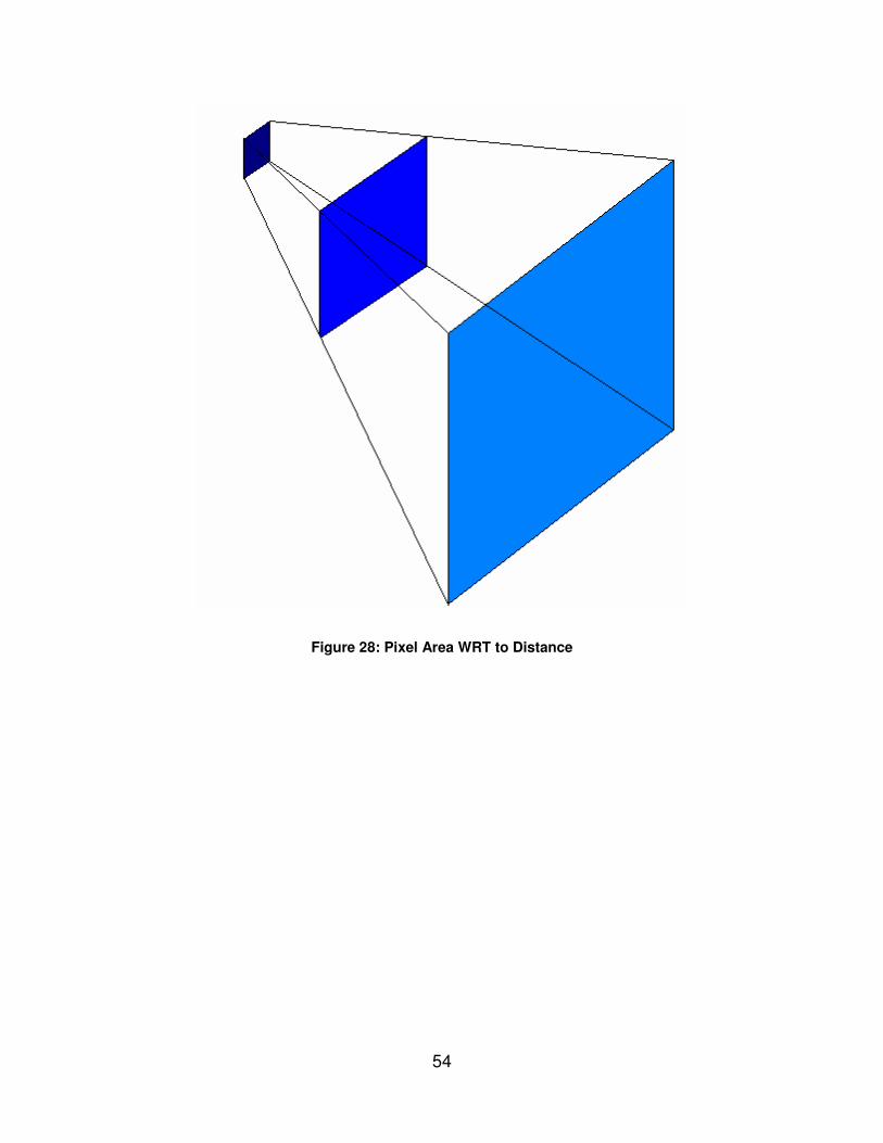
appear in both the X and Y directions. This behavior is illustrated below in Figure 29.
This author’s best estimate as what causes these anomalies relates to disparity error
caused by the discrete nature of the pixels on the CCD. Motion in the real world is
analog and continuous. The CCD has a finite resolution and, thus, each pixel
associates with a square of visual data that gets larger and larger as the region of
interest moves farther away from the camera. (Figure 28) This anomaly appears to
come from only the X & Z directions because the X direction is used to calculate the Z
value and the X direction is the one in which the natural, desired, disparity occurs. The
Y value in both the left and right are virtually identical and are not their disparity is not
even analyzed.
54
Figure 28: Pixel Area WRT to Distance

55
Figure 29: Motion Artifact Illustration

56
Each graph is titled either X, Y, or Z. These graphs correspond to what recorded
motion has taken place in the X, Y, and Z directions. The motion that formed these
graphs involved moving an object of interest 1 meter first in the Y, then the X, then the Z
direction. That is, first up and down, then left and right, then out and in. The blue
circles identify portions of the motion that correspond to actual movement. The red
circles identify apparent motion that did not actually happen. These sections are
caused by artifact motion from either the X or Z motion.
To get rid of the artifacts a filter was developed which has been called the
Difference Filter. This filter was devised by this author after analysis of graphs, similar
to those in Figure 29, in Microsoft Excel. It was found that the anomalies corresponded
to the motion in other directions exactly, from both a temporal and relative magnitude
standpoint. Experimentation was then done to develop the appropriate equations. The
filter simply subtracts a scaled version of the offending cardinal direction from the
affected direction. The Difference Filter works according to the equations shown in
Figure 30. The values of 0.008 and 0.025 were found experimentally. An example of
difference filtering on the Y axis of the same motion example can be seen below in
Figure 31. It is the opinion of this author that no better, and if so only marginally better,
results could be achieved using a more complex and computationally intensive higher-
order filter.
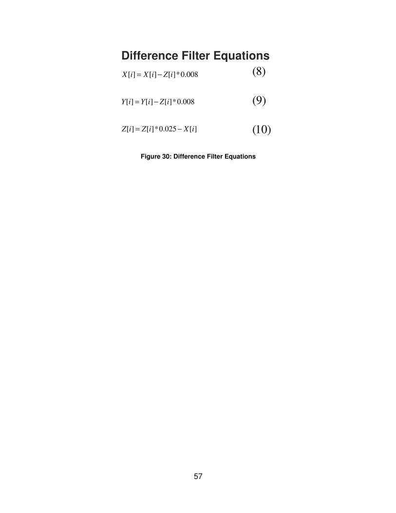
57
Figure 30: Difference Filter Equations
[ ] [ ] [ ]*0.008X i X i Z i= −
[ ] [ ] [ ]*0.008Y i Y i Z i= −
[ ] [ ]*0.025 [ ]Z i Z i X i= −
Difference Filter Equations
(8)
(9)
(10)

58
Figure 31: Difference Filter on Y

59
The first graph is of the unfiltered Y signal. The second graph shows the same signal
after undergoing a difference filter where the Z signal (which is effected by X artifacts as
well) scaled by 0.008 and then subtracted from the original Y signal. Again, the red
circle indicates where the artifact motion was. The blue circle identifies the actual,
desired, Y motion. Its shape and relative magnitude are left unchanged.
Most of the experimentation with the difference filter was done using Microsoft
Excel. In order for the difference filter to be included into the system it had to be
implemented in C++ which turned out to be fairly involved. Since the code is quite long
Figure 32 shows pseudo-code to help you understand how it was implemented. The full
code can be found at the end of this document in the code listing under the
filterCoords function.

60
void filterCoords(char coords[], char tempcoords[], char filteredcoords[])
{
//FILTER PASS 1 (DIFFERENCE OF X & Y)
coordsfile = fopen(coords, "r"); //open coordinates
tempfile = fopen(tempcoords, "w"); //open file to write too
fclose(coordsfile);
//start at the beginning of the file
coordsfile = fopen(coords, "r"); //open coordinates
while(fgets(coordsfile) != NULL) //loop through coordsfile
{
line = fgets(coordsfile); //get a line from coordsfile
//difference filter X & Y
dfiltered[X]=line[X]-line[Z]*.008;
dfiltered[Y]=line[Y]-line[Z]*.008;
//save line to tempcoords file
fprintf(tempfile, dfiltered[X], dfilterd[Y], dfiltered[Z]);
}
//close files
fclose(coordsfile)
//FILTER PASS 2 (DIFFERENCE FILTER Z)
coordsfile = fopen(tempcoords, "r"); //open temp coordinates
filteredfile = fopen(filteredcoords, "w"); //open write file
while(fgets(coordsfile) != NULL) //loop through coordsfile
{
//get next line
line=fgets(coordsfile);
//difference filter Z
dfiltered[Z]=line[Z]/40-line[X];
//print line to file
fprintf(filteredfile, dfiltered[X], dfilterd[Y],
dfiltered[Z]);
}
}
Figure 32: filterCoords pseudo-code
As the comments in the pseudo-code suggest, the filtering is split into 2 passes. This is
because the filtered X signal must used for the difference filtering of the Z signal,

61
otherwise the Z signal’s presence in the X signal would entirely cancel it out. The code
begins by opening up the appropriate text files. A while loop then beings which cycles
through every entry in the coordinates file. Each entry is then Difference filtered. The
filtered point is then written to a new, temporary, file. Once the first pass is completed,
the second pass is begun which applies the Difference filter to the Z signal. This pass
has the same basic structure as the first pass. This second pass uses the output of the
first pass as its input and writes to the final filtered coordinates file.
III.2.4. Compressing the Coordinates
Once the filtering of the coordinates has been completed there are still many
more data points than is necessary to describe the generalize motion of the target
objects. It is important to reiterate that, in the project, the goal has been to replicate the
gestures of a human user. Where possible the system has been modeled in such a
way as to approximate human behavior both in method and result. If a human were to
replicate another human’s gestures an exact measure of their movements would not be
taken. Instead a general sense of the motion would be gathered by focusing on the
major changes in velocity and direction. Compression takes place here in a similar
fashion with similar motivations and results.
Generally speaking, the system looks for changes in direction of the motion on a
specific axis. When that change in direction is found the system checks to see if there
is sufficient is a change magnitude when compared to the previous change in direction.

62
This acts as a final filter to eliminate insignificant motion or noise in the system. Figure
33 displays the pseudo-code for the point compression.
void compressCoords(char coords[], char compressedcoords[])
{
coordsfile = fopen(coords, "r"); //open uncompressed coords
compressedfile = fopen(compressedcoords1 "w"); //open file to
//hold compressed
//coords
//get 1st uncompressed XYZ point, print, & save as lastpoint
lastpoint=fgets(coordsfile);
fprintf(compressedfile, lastpoint); //print 1st line to output
lastsavedpoint = lastpoint; //fill in last saved point buffer
currpoint=fgets(coordsfile); //get 2nd uncompressed XYZ point
//and save as currpoint
//set the direction of each axis
for(i=1;i<4;i++)
{
pointdiff[i] = currpoint[i] – lastpoint[i];
if (pointdiff[i] > 0) direction[i]=1;
else if (pointdiff[i] < 0) direction[i]=-1;
else direction[i]=0;
}
while(1) //loop through the rest of the uncompressed points
{
lastpoint=currpoint; //update last point
currpoint=fgets(coordsfile); //get the next point
//if we reach the end of the file, break out of the loop
if(currpoint = NULL) break;
//get temporary directions
for(i=1;i<4;i++)
{
pointdiff[i] = currpoint[i] – lastpoint[i];
if (pointdiff[i] > 0) temppdir[i]=1;
else if (pointdiff[i] < 0) temppdir[i]=-1;
else temppdir[i]=0;
}
//check for changes in direction, if a change is found
//check that the magnitude of the change is large enough
for(i=1;i<4;i++)
{

63
if (tempdir[i] != direction[i])
{
if(abs(currpoint[i]-lastsavedpoint[i]) > 1000)
changeflag = 1;
}
}
//if a change has occurred, print & save the point
if (changeflag)
{
fprintf(compressedfile, lastpoint);
lastsavedpoint = lastpoint;
}
changeflag=0; //reset changeflag
//update directions
direction=tempdir;
}
}
Figure 33: compressCoords pseudo-code
The code begins by opening the uncompressed coordinates file and creating a file to
hold the compressed results. The first point is then read in and saved as the
lastpoint and lastsavedpoint. The lastpoint is the most recently opened
by before the current point and is used to check for a change in direction. The
lastsavedpoint is that most recent point that has been identified as a suitable
change of direction point and has been saved to the compressed output file. Next the
second point is retrieved and saved as the currpoint (current point). The
currpoint and lastpoint are used to calculate the initial direction, that is, does
the signal in the X, Y, & Z directions have a positive or negative slope. This is done by
subtracting the last point from the current point. If the number is positive, that means
that the currentpoint has a greater magnitude then the last point and the slope is

64
positive. If it is negative then the slope is negative. If the answer is 0 they have the
same magnitude. Now the main loop can begin and the rest of the points can be
analyzed. The loop first updates the lastpoint and then gets the next point in the
file. If that attempt returns NULL it means that the end of the file has been reached and
it is necessary to break out of the loop. Temporary directions are then found for the
current point versus the last point in the same manner as the original directions were
found. The temporary directions (tempdir) are then checked against the previous
directions (directions), if an inconsistency is found in either X, Y, or Z, that means
that a change in direction has occurred. The change is then checked for magnitude by
subtraction of the current and last points. If the change is less then 1000, it is ignored.
If it is greater, it is considered significant enough to be recognized and the
changeflag is set from 0 to 1 to indicate that a valid change in direction has
occurred. If a change has occurred then the point is saved to the compressed points
output and the lastsavedpoint buffer is updated. Regardless of the state of
changeflag it is then reset to 0 and the directions are updated. This process
continues until the entire set of points has been analyzed. Figure 34, below, shows a
graphical representation of this technique in action.

65
Figure 34: Compression on Y

66
The compression algorithm is designed to save points that represent a major change in
direction of the X, Y or Z signals. The beginning of the graph from 28 to 35 shows an
excellent example of where the Y signal was the driving factor for points being saved.
The rest of the graph, from points 36 to 56, contains points that were saved due to
changes in either the X or Z directions. The last point at 57 is due to the removal the
object of interest from ISAC’s field of view at the end of the test. As the graph
demonstrates, a significant amount of compression takes place while the general shape
of the signal is still maintained. In this particular case the number of points was reduced
from 276 points to 29 points. In this case, the signal is adequately represented by 90%
fewer points. The number of necessary points in this example would be significantly
less if the only sizable motion in the test was in the Y direction because almost all of the
points on the graph between 35 and 57 would be eliminated bringing the total point
count down to about 10.
III.2.5. Fitting the Coordinates to ISAC’s Workspace
Once filtering and compression have been completed the coordinates are still in
relative units. These units are not compatible with ISAC’s workspace. In addition, ISAC
represents the world as a rotation of the original representation of the world. Where
originally, the Y is vertical, X horizontal, and Z away from ISAC, ISAC sees the world
with Z being vertical, Y horizontal, and X away from himself. To make the coordinates
compatible a conversion was necessary. This conversion, essentially, switches the
axes appropriately and further alters the coordinate signals to fit within ISAC’s

67
workspace. This involves both a scaling and a shift. ISAC’s workspace is an irregular
manifold. To simplify calculations, a cubic subset of ISAC’s workspace was used. To
calculate these scaling and shift factors a sample workspace for ISAC was analyzed a
method for finding the appropriate factors automatically was devised. The method
works by first finding the minimum and maximum values of X, Y, & Z. Then calculating
their difference to find the range of a given direction. The range is divided by ISAC’s
range to come up with a scale factor in X, Y & Z. Then a shift factor is computed by
dividing a known point in the original space by the scale factor and subtracting the
associated known point in ISAC’s space. Figure 35, below, shows the pseudo-code
that carries out this operation.

68
void fitCoordsToISAC2(char coords[], char fittedcoords[], int rl)
{
coordsfile = fopen(coords); //open our coords for reading
fittedfile = fopen(fittedcoords); //open a new file for output
//initialize maxs and mins
for(i=1;i<4;i++)
{
maxs[i]=-999999999999;
mins[i]=999999999999;
}
//find the maxs and mins for X, Y, & Z
for(;;)
{
//get the next point in the file
currpoint=fgets(coordsfile);
//if we have reached the end of the file, break the loop
if (currpoint == NULL) break;
//find current maxs/mins
for(i=1;i<4;i++)
{
//maxs
if(currpoint[i]>maxs[i]) maxs[i] = currpoint[i];
//mins
if(currpoint[[i]<mins[i]) mins[i] = currpoint[i];
}
}
fclose(coordsfile);
//CALCULATE DIFFERENCES
for(i=1;i<4;i++)
{
diffs[i]=maxs[i]-mins[i]; //get the range of each axes
}
//FIND BIGGEST RANGE & DIVIDE DIFFERENCE BY ISAC'S RANGE
if(diffs[1] > diffs[2])
{
//ensure movement is greater then a minimum
if (diffs[1] > MIN_MOVEMENT)
div = diffs[1]/(ISAC_Y_MAX-ISAC_Y_MIN);
else
no_move = 1;
}
else
{
//ensure movement is greater then a minimum
if (diffs[2] > MIN_MOVEMENT)
div = diffs[2]/(ISAC_Z_MAX-ISAC_Z_MIN);
else
no_move = 1;
}

69
//CALCULATE SHIFT FACTOR based on Face Location
shift[1]=(mins[1][1]/div-FACE_Y)*-1;
shift[2]=(maxs[1][2]/div-FACE_Z)*-1;
//IF RIGHT ARM :: GET LARGEST LEFT/RIGHT (X->Y) VALUE
armshift = maxs[1][1]/div+shift[1];
coordsfile = fopen(coords); //open our coords for reading
//REWRITE FILE LINE BY LINE APPLYING SCALE & SHIFT & REARRANGE
for(;;)
{
currpoint = fgets(coordsfile); //get the next point
if(currpoint == NULL) break; //if we reach EOF, break loop
modpoint[0]=currpoint[0] //new TIME = old TIME
//scale & shift the point
for(i=1;i<4;i++)
modpoint[i]=currpoint[i]/div+shift[i];
if (rl == RIGHT_ARM) //shift if right arm
modpoint[1]=modpoint[1]-armshift;
//SAFTEY SHIFT
//shift the points further from the center to ensure ISAC
wont hit his own hands together
if (rl == RIGHT_ARM)
modpoint[1]=modpoint[1]-SAFETY_SHIFT;
else
modpoint[1]=modpoint[1]+SAFETY_SHIFT;
//write to the new file in ISAC's order
if (no_move)
fprintf(fittedcoordsfile,"%f,%f,%f,%f\n",modpoint[0],
FOREARM+HAND_L,CENTER_TO_ANGLE_0+SHOULDER_OFFSET,-
UPPERARM);
else
fprintf(fittedcoordsfile,"%f,%f,%f,%f\n",modpoint[0],
CONST_X,modpoint[1],modpoint[2]);
}
//close our file handles
fclose(coordsfile);
fclose(fittedfile);
}
Figure 35: fitCoordsToISAC pseudo-code

70
The function, like most, begins by opening the existing coordinates file for reading and a
second, empty file, for writing the output to. The maxs and mins are then initialized to
very large and very small values, respectively. The actual maxs and mins of each axis
are then found by looping through the points, and recording the largest and smallest
values replacing them when necessary. Once the maxs and mins are found the
computation of the scale and shift factors begins. First the differences of each max and
min set (X, Y, Z) are found. These differences represent the range of each signal.
Then the X & Y ranges are compared to find the larger of the two. We then take
whichever is larger and use that to compute our scaling factor. If the larger of the two is
still below a certain MIN_MOVEMENT threshold then the movement is ignored entirely
and that arm is instructed to remain in the home position. Assuming that there is
suitable movement detected, the larger difference is divided by ISAC’s range in that
direction and that value is used as our scaling factor. This scaling factor allows for the
recorded points to be put into ISAC’s range. Next the shift factor is calculated according
to the location of the gesture movements relative to the face. A second shift factor that
applies only to ISAC’s Y motion is then calculated to be applied to the right arm points
only. This is done because all of the left and right calculations are virtually identical,
and much of the code can be reused if the concession is made to shift the right arm
points over at the end. The point is then scaled and shifted according to the previously
calculated values. A final “safety shift” is then applied to further move ISAC’s arms
apart from one another. Finally the scaled and shifted point is written to the
fittedcoords output file. The axes are written in a modified order to apply the

71
rotation to ISAC’s workspace and the X value is written as a constant CONST_X. This
is done because ISAC’s range in the X direction is very limited and looks proper.
III.2.6. Calculating Joint Angles
The systems calls for approximate mimicking of arm sized gestures. A discrete
Inverse Kinematics routine exists. However, for it interface smoothly with the rest of the
Processing Subsystem a function must exist to call the Inverse Kinematics routine for
each point. This function is called calcJointAngles and its pseudo-code is shown
below in Figure 36.

72
void calcJointAngles(char coords[], char angles[], int rightleft, int EndEff,
int simple)
if(!simple)
pdAngles = new double[6];
coordsfile = fopen(coords); //open our input file
anglesfile = fopen(angles); //open out output file
for(;;)
{
//get the next point in the file
currpoint=fgets(coordsfile);
//breakout of the loop if we reach EOF
if (currpoint=NULL) break;
//convert points to appropriate container
if(simple)
{
point.x = currpoint[1];
point.y = currpoint[2];
point.z = currpoint[3];
}
else
{
for(j=0;j<3;j++)
pdPos[j]=currpoint[j+1];
}
//INVERSE KINEMATICS
if(simple)
pdAngles = simpleInverseKinematics(point, rightleft);
else
inverseKinematics(pdPos, pdAngles, (short)rightleft,
(short)EndEff);
//write time + joint angles to the new joint angles file
fprintf(anglesfile,
"%f,%f,%f,%f,%f,%f,%f\n",currpoint[0],pdAngles[0],pdA
ngles[1],pdAngles[2],pdAngles[3],pdAngles[4],
pdAngles[5]);
}
}
Figure 36: calcJointAngles pseudo-code
This function is essentially a wrapper for the actual Inverse Kinematics. This function
allows the user to pass it an entire set of points to be converted and also gives a choice

73
between a simple and a complex Inverse Kinematics model. The primary difference
being whether all joints should be considered or the roll joints (3 and 5) should be
ignored. The function begins by opening out the input and output files. Then the input
file is looped through and as points are read out of it, the input parameters are checked.
If a simple model has been requested, then the point is formatted in a CvPoint3D32f
and passed along to the simpleInverseKinematics. If a complex model has
been requested, then the point is formatted in the appropriate array and passed along to
it. The request for a right or left arm consideration is passed along as well. The end
effector variable is only used for the complex model and is supposed to ignore then end
effector when set to 0. In practical testing, however, it does not perform up to
expectations. Since the simple Inverse Kinematics model is the model of choice, the
complex model will be left at that. The simple model is described in greater detail now.
It is not required that the gripper approach the desired point from a certain
direction or with a specific orientation. Therefore the Inverse Kinematics, which allow
joint angles to be calculated from a desired 3D point, can be greatly simplified by
ignoring the gripper and its complex axes of rotation. When the gripper is not
considered, the Inverse Kinematics becomes that of a 3 link manipulator. Angles 0
relates to the rotation of the shoulder about an axis parallel to ISAC’s Z axis. Angles 1
& 2 relate to the extension of ISAC’s arm at the shoulder and elbow. This configuration
allows the Inverse Kinematics to be split into two sub-problems. Angle 0 can be
calculated by considering the X & Y coordinates done in such a way as to cause the
arm to “point” toward its intended target. Then angles 1 & 2 can be calculated using
only the X & Z coordinates to cause the arm to reach out the appropriate distance.

74
Geometry was used to determine the appropriate angles of joints 0, 1 & 2. Figure 37
displays a graphical representation of the two different cases for angle 0 along with the
associated equations.
Figure 37: Angle 0 graphs and equations
Figure 38 displays a graphical representation of the angles 1 & 2 and associated
equations. The equations used to calculate angles 1 & 2 were taken directly from the
geometric discussion of a 2 link manipulator in Modelling and Control of Robot
Manipulators pgs. 68-69 [28].
arccosa
b
cθ
=
arctanb
x
a yθ
=
−
( )sinb
xc
θ=
0 a bθ π θ θ= − −
arctana
x
y aθ
=
−
sinarccos a
b
b
x
θθ
=
0 b aθ θ θ= −
(11)
(12)
(13)
(14)
(15)
(16)
(17)

75
Figure 38: Angles 1 & 2 graph and equations
Lastly, although it is not considered in the calculation of joint angles relative to
the target 3D location angle 4 is calculated as well. Instead of attempting to aim the tip
of the gripper at the target point the gripper instead points directly up. This is to help
give the illusion that ISAC is waving and gesturing back in a realistic manner. Angling
the gripper upward exposes ISAC “palm” to the user. FIGURE Z shows a graphical
representation of this situation and the corresponding equation used to calculate angle
4.
2 2 2 2
22
p px y u fc
uf
+ − −=
( )2 2arccosv c=
arctanp
p
y
xα
=
2 2 2 2
2 2arccos
2
p p
p p
x y u f
u x yβ
+ + + = +
1θ α β= +2 2
2v
πθ = − − (22), (23)
(20)
(19)
(18)
(21)

76
Figure 39: Angle 4 graph & equation
All of these equations were then, of course, translated into C++ code for which
the pseudo-code can be seen below in Figure 40.
( )4 1 2θ π θ θ= − + + (24)

77
double* simpleInverseKinematics(CvPoint3D32f point)
{
//set constant holders
a = CENTER_TO_ANGLE_0;
b = SHOULDER_OFFSET;
u = UPPERARM;
f = FOREARM;
h = HAND_L;
//adjust x, y, z for math
x = point.x;
y = point.y;
z = -point.z;
//Calculate Theta 0 (shoulder X Y)
if (y >= a)
{
Ta = atan(x/(y - a));
Tb = acos(b*sin(Ta)/x);
T0 = Tb - Ta;
}
else
{
n = a - y;
Tb = atan(x/n);
o = x/sin(Tb);
Ta = acos(b/o);
T0 = -(PI - Ta - Tb);
}
//Calculate Theta 1 (elbow) & Theta 2 (shoulder X Z)
alpha = atan2(z,x);
beta = acos((x*x+z*z+u*u-(f+h)*(f+h))/(2*u*sqrt(x*x+z*z)));
c2 = (x*x + z*z - u*u - (f+h))/(2*u*(f+h));
v1 = alpha + beta;
v2 = acos(c2);
//conversion to ISAC's frame
T1 = v1;
T2 = -v2 - PI/2;
//Calculate Theta 4 (wrist up/down)
T4 = -(PI + T1 + T2);
//populate return array in degrees
ret[0]=T0; ret[1]=T1; ret[2]=T2; ret[3]=0; ret[4]=T4; ret[5]=0;
return ret;
}
Figure 40: simpleInverseKinematics pseudo-code

78
The function follows the equations laid out in FIGURES X & Y exactly. The output of
the function is a 6 element array that corresponds to ISAC’s 6 joints. As evident in the
code, the return array is populated by the calculated theta values except angles 3 and 5
which are purposefully set to 0 as they correspond to the roll of the forearm and wrist,
respectively.
III.2.7. interpolateAngles Function
Having ISAC move from one point to another that is physically distant cause
visually violent motion. In addition to this being visually displeasing it also increases the
likelihood that ISAC damages himself through the aggressive motion. This damage
could manifest itself as a simple misaligned chain or it could be more destructive such
as a blow muscle. To avoid this situation an interpolateAngles function was
devise. This function’s purpose is to create a set of intermediate points between two
original points. This does not conflict with the compressCoords function (section
III.2.4) as they serve different purposes. compressCoords eliminates the notion of
variable acceleration in the movement. The interpolateAngles function aims to
maintain this constant acceleration while smoothing out ISAC’s movement. Figure 41
displays the interpolateAngles pseudo-code.

79
void interpolateAngles(char anglesIn[], char anglesOut[])
{
anglesInFile = fopen(anglesIn); //open input
anglesOutFile = fopen(anglesOut); //open output
//get 1st line from anglesIn
lastangle = fgets(anglesIn);
while(1) //loop forever
{
//get a line from anglesIn
currangles = fgets(anglesIn);
if (currangles == NULL) break; //if we reach EOF, break
//get the time between 2 sets of angles
span = currangles[0] - lastangles[0];
//calculate increments for interpolation
for(i=1;i<7;i++)
{
increments[i]=(currangles[i] - lastangles[i])/span;
}
//write original point + new interpolated points
for(i=0;i<span;i++)
{
fprintf(anglesOutFile,"%f,%f,%f,%f,%f,%f,%f\n",
lastangles[0]+i,
lastangles[1]+i*increments[1],
lastangles[2]+i*increments[2],
lastangles[3]+i*increments[3],
lastangles[4]+i*increments[4],
lastangles[5]+i*increments[5],
lastangles[6]+i*increments[6]);
}
//update lastpoint
for(i=0;i<7;i++)
lastangles[i]=currangles[i];
}
//print out the last point
fprintf(anglesOutFile,"%f,%f,%f,%f,%f,%f,%f\n",lastangles[0],
lastangles[1],lastangles[2],lastangles[3],
lastangles[4],lastangles[5],lastangles[6]);
//close files
fclose(anglesInFile);
fclose(anglesOutFile);
}
Figure 41: interpolateAngles pseudo-code

80
The interpolateAngles function begins by recording the 1st set of angles in the
lastangles variable. Then the rest of the file is iterated through. During each
iteration the new point is read into currangles. The span variable is calculated to
be the range between the currangles time variable and the lastangles time
variable. This tells the function how many points to create in-between. By using a
variable number of interim points, the timing is kept consistent. The function then
calculates the increments necessary to go from the lastangles value to the
currangles value in number of time steps represented by span. The
lastangles along with the new interpolated angles are then written to the output
file. This continues until the last point is reached at which time the loop breaks out and
the last point is written
III.2.8. Uploading The Coordinates To ISAC’s Control Systems
The final step that is executed on the machine Sally is to upload the coordinates
to a location that can be accessed by the Arm Control System which is located on a,
physically, separate machine known as Octavia. This is done by simply reading the
final filtered, compressed, and fitted coordinates file and writing it onto a shared location
at I:/Temp/uploadL.txt and I:/Temp/uploadR.txt corresponding to the
points that the left and right arms should follow. The, condensed, code is show below in
Figure 42.

81
void uploadCoordsToNNbatch(char uploadL[], char uploadR[], char coordsL[],
char coordsR[])
{
char line [512]; //holder for a single line of a coordsfile as
//it is parsed
FILE *uploadfileL; //file handle for temp upload file to send
//info to the NN L
FILE *uploadfileR; //file handle for temp upload file to send
//info to the NN R
FILE *coordsfileL; //file handle for coords to be uploaded L
FILE *coordsfileR; //file handle for coords to be uploaded R
//open coords files
coordsfileL = fopen(coordsL, "r"); //coordinates to be uploaded
coordsfileR = fopen(coordsR, "r"); //coordinates to be uploaded
uploadfileL = fopen(uploadL, "w");
uploadfileR = fopen(uploadR, "w");
//copy to a text file on the shared I drive for use by the Neural
//Network Controller
for(;;)
{
if(fgets(line, 512, coordsfileL) != NULL)
{
fprintf(uploadfileL, line);
}
else break; //if we reach EOF, break out of the loop
}
for(;;)
{
if(fgets(line, 512, coordsfileR) != NULL)
{
fprintf(uploadfileR, line);
}
else break; //if we reach EOF, break out of the loop
}
fclose(uploadfileL);
fclose(uploadfileR);
fclose(coordsfileL);
fclose(coordsfileR);
}
Figure 42: uploadCoordsToNNbatch (condensed)
After the declaration of variables, the function starts by opening up 2 local coordinates
files that correspond to the left and right arms’ paths. Then 2 files are opened up for

82
uploading purposes that are on a shared network drive. The next step is repeated
twice, once for each set. A loop is setup and a line is simply read from the local drive
and written to the network drive until the upload is completed.
III.3. Control/Arm System
While Vision and Processing are bundled together on the Windows XP machine
Sally, the Control System is separate on located on a Windows 2000 Machine named
Octavia. The system is built on the locally written Neural Network / PID Controller by
Erdemir and Ulatas. Their contribution is discussed in more detail in section II.4.3. The
rest of this section will describe the controller as it relates to the project.
III.3.1. The Controller
The actual controller is a combination Neural Network / PID controller. At its
most basic level it works like this. The controller takes in a set of joint angles, which is
fed to a lookup table whose values have been populated using a Neural Network
training method. This lookup table associates joint angles to specific air pressures that
should be in each muscle represented by voltages than need to be applied to the
valves. A certain amount of time is given for this portion of the controller to bring the
arm as close to the objective point as possible. Then the PID portion kicks in. This
portion reads in actual joint angles, computes the location that the arm is reaching to,
and compares it to the objective point. If the points do not match, then adjustments are
made. This is continued for set amount of time to give the arm a chance to reach its
83
destination. Either one of these sections can be disabled making the controller purely
Neural Network or purely PID based.
III.3.2. The Modifications
The original design of the controller had the desired point hard coded in and
allowed for only a single point to be reached to per run of the software. The devised
system requires that a set of points be achieved in series. The bulk of the modifications
to the controller revolved around making this happen. The modifications started with
the replacement of the hard coded goal point with code that opened up a text file and
read the desired point in. This text file corresponds to the file uploaded by the Vision
and Processing System. The entire main function was then wrapped in a loop that
would allow for multiple points to be read in and moved to in succession. Several minor
modifications were necessary to make this all happen but they were mostly minutiae
related to coding, not to the essence of the software.
III.3.3. Integration with the Vision & Processing Systems
The integration of the Control System with the Vision & Processing Systems is
fairly straight forward. Wrapping both systems in TCP/IP code and having the system
communicate live over the network was considered. Upon further scrutiny, however, it
was decided that approach was unnecessary and added complexity but did not
enhance the capabilities of the system itself. Instead a simpler approach was taken.
The Control System is started up first. The Vision & Processing System is started up

84
second. The Vision & Processing Systems works through, as described in sections III.1
and III.2, and finish their execution by first uploading the coordinates files to I:/Temp
and then uploading an indicator file. Meanwhile, the Control System is sitting in a loop
searching for this indicator file. When it finds it, it begins execution by downloading the
coordinates files. When the Control System has completed, it deletes the indicator file
resetting for another run.

85
CHAPTER IV
EXPERIMENT
IV. EXPERIMENT
IV.1. Goals
Due to the nature of the project, the results are necessarily subjective. The goal
of the project was to create a system by which ISAC could see and mimicking arm
gestures. Thus, the final output of the system is the movement of ISAC’s arms and the
main standard by which the quality is measured lies with the observer. This makes
traditional experimentation difficult. A truly in-depth experiment regarding the quality of
the yield of this project would require something akin to a double blind study where by
the individual observing the output would have no knowledge of the input and
associates would be need to be made. This type of experiment is outside the scope of
this project and besides that, the logic fails in a minor way. The system has been
designed to allow ISAC to repeat a gesture back to a user. Therefore, given the current
design of the system and the original project goals, the individual observing the
system’s output will always be either the user supplying the input or another individual
within close proximity who has had the opportunity to see both the input and the output.
Therefore, the specific goal of this experiment will be a subjective one whereby the user
supplying the input will have to judge whether the output is sufficiently similar.
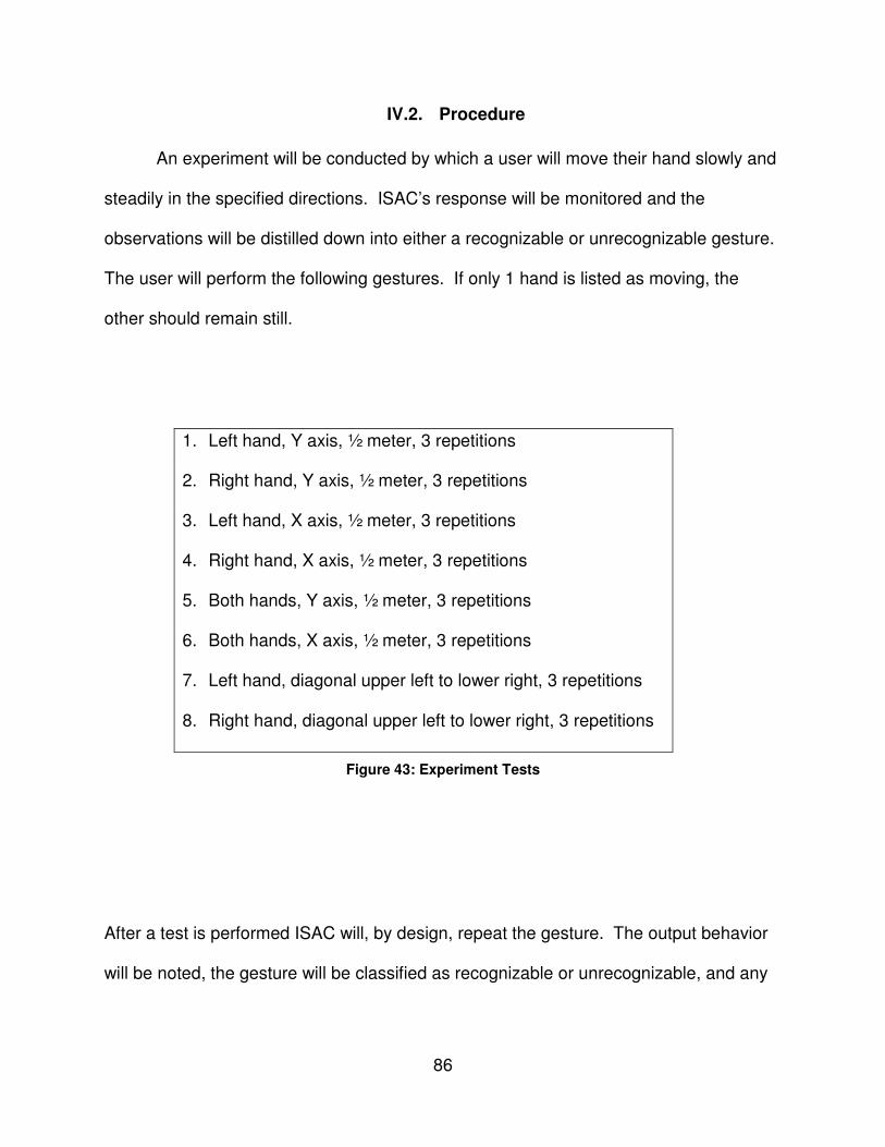
86
IV.2. Procedure
An experiment will be conducted by which a user will move their hand slowly and
steadily in the specified directions. ISAC’s response will be monitored and the
observations will be distilled down into either a recognizable or unrecognizable gesture.
The user will perform the following gestures. If only 1 hand is listed as moving, the
other should remain still.
1. Left hand, Y axis, ½ meter, 3 repetitions
2. Right hand, Y axis, ½ meter, 3 repetitions
3. Left hand, X axis, ½ meter, 3 repetitions
4. Right hand, X axis, ½ meter, 3 repetitions
5. Both hands, Y axis, ½ meter, 3 repetitions
6. Both hands, X axis, ½ meter, 3 repetitions
7. Left hand, diagonal upper left to lower right, 3 repetitions
8. Right hand, diagonal upper left to lower right, 3 repetitions
Figure 43: Experiment Tests
After a test is performed ISAC will, by design, repeat the gesture. The output behavior
will be noted, the gesture will be classified as recognizable or unrecognizable, and any

87
abnormalities will be noted. Additional an approximation of the range of ISAC’s
repeated motion will be given.
IV.3. Results
Trial # Recognizable? ≈Distance
Moved Notes
1 Yes 24” A bit of extra Z motion ≈12” 2 Yes 24” A bit too low 3 Yes 20” Forearm flops at apex 4 Yes 20” - 5 Yes 20” Movement is a bit out of sync 6 Yes 20” Forearm flops at apex 7 Yes 18” - 8 Yes 18” -
Figure 44: Experiment Results
IV.4. Discussion
Overall the results of the experiment were deemed acceptable. There are areas
where the motion could be improved. Most of this work will go into the controller and
devising ways of providing for smooth movement. As was noted in Figure 44, in some
cases there was extraneous movement. This implies that, while the human operators
movement was primarily in, say, the Y direction, there was some output movement in
another direction. While this occurred it was of a lesser magnitude then the intended
movement and did not hinder the gesture as being recognizable.

88
Trial 1 involved moving the left hand back and forth along the Y axis a distance if
½ meter. The results were good although there was a bit of movement in the Z axis
that was not desired. This is partially due to error inherent to the disparity calculations
and partially due to error in the Neural Network. The arm moved over approximately a
24” range.
Trial 2 was a copy of trial 1 using the right hand instead of the left hand. Again
the movement was good, there was a slight bit of extraneous Z axis motion and the
entire motion occurred over a range of approximately 24”.
Trials 3 and 4 were very good. They had the user moving their left and right
hands, independently, up and down a distance of ½ meter. ISAC repeated these
actions very well although the left forearm has a tendency to fall back onto the left
upperarm when it passes vertical. This is because, in the current architecture of ISAC,
the rear upper-arm muscles have been disabled. This provides no tension to avoid this
problem displayed here. The movement ranged over approximately 20” in both trials.
Trials 5 performed well, very similar to trials 1 and 2 although a new, minor issue,
was introduced. There is a bit of a temporal shift in one arm compared to the other.
What this means is that, although the user moved their arms in sync, ISAC moved his
arms out of sync.
Trial 6 was very good and very similar to trials 3 and 4. The left arm suffered
from the same problem as in trial 3. This problem is not as apparent in ISAC’s right arm
because ISAC’s right gripper is lighter then his left. This puts less torque on the right
elbow. The motion in this trial was approximately 20” for both arms.

89
Trials 7 and 8 were very good as well. The motion was quite recognizable and
the only issue to speak of was in smoothness of motion. An upgrade to the controller
would help to work out this problem. It is necessary that the controller operate at a fast
enough pace to keep the arms in motion. Jerkiness appears when the arm is asked to
start and stop at each via point along its path. The motion in both trials 7 and 8
occurred over a path of approximately 18”.
As a basis for Imitation Learning the entire project is considered a success. It is
this author’s hope that future work goes into the project to improve it in every way
possible. Many areas for improvement are been discussed in section V.2.1.

90
CHAPTER VI
WRAP-UP
V. WRAP-UP
V.1. Conclusion
Throughout many months of work, this project has gone from experiments with a
cheap webcam to a fully functional system that employs most all of ISAC’s available
hardware to complete its goal. The system successfully bestows the ability to track
simple arm gestures, performed by a human user, and repeat said arm gestures back in
a recognizable way. Throughout the development many surprises were overcome.
Additionally many subsystems were created that were not originally anticipated.
Improvements to the Neural Network based controller and a complete, from scratch,
creation of an Inverse Kinematics solution were not expected but proved beneficial to
the system. The entire concept of filtering the signals was not projected. However, it
was, like all other obstacles overcome. The system effectively combines elements of
computer vision, signal processing, kinematics, and control systems to achieve the
goals set forth at the start of the project and is considered a success.
V.2. Recommendations for Future Work
While the system that has been developed is quite robust and flexible there is, of
course, room for improvement. In addition the creation of the system has led to the
91
development of several ideas for tangent projects that could be beneficial. This section
will describe the possible improvements and potential projects that have arisen out of
the months of work that have gone into the system.
V.2.1. Improvements to the Current System
V.2.1.1. Save/Load of frames as BMPs
There are several instances where a shortcut was taken and those areas should
be revisited. The instances in question never hurt the functionality of the software but
sometimes would result in lower performance. The first instance is in the retrieving of
frames from the cameras and loading of said frames into IplImage structures. In the
current version of the software, the retrieved frames are saved as a BMP file on the
local hard drive of the machine and then reopened and loaded into an IplImage
structure. This, of course, is functional but it is the opinion of this author that higher
performance could be achieved during the recording of the gestures if this step of
saving as and open up a BMP file could be eliminated. Ideally the frame, retrieved from
the cameras would be loaded directly into an IplImage structure.
V.2.1.2. Colored Gloves
The current setup requires that the user wear brightly colored gloves or hold
brightly colored objects to assist in the detection of the hands. The initial exploration of
the project found that Haar-detection of hands was not feasible given the types of
sample image that were able to be generated in the lab. In addition detecting hands

92
using color segmentation proved difficult as most of the lab environment is of a hue
similar to human skin. The walls are beige, the doors and shelves are tan. Both of
these colors share the same basic hue as human skin. It would be ideal if the colored
gloves requirement could be lifted. This could come about by revisiting Haar detection,
exploring Kalman filters, or investigating some other technology. Perhaps a
combination of existing technologies would prove effective. Regardless, the colored
gloves requirement is the only requirement related to the user wearing equipment and it
would be practical to eliminate it.
V.2.1.3. Keyboard Start/Stop of Gesture Recording
At the present time, the recording of a user’s gesture is started and stopped via a
keystroke on the keyboard of the Sally PC. This makes it difficult for a single user
interact with ISAC using the system and it also acts as a deterrent for repeated gestures
mimicking, although it does not prohibit it. Modification to the start/stop mechanism to
eliminate this reliance on the keyboard would be useful. One possibility is to integrate
voice recognition and allow the user to start and stop gesture recording with a voice
command. Perhaps a specific gesture, such as the shake of the both hands, could
initiate gesture recording. A discontinuation in hand movement could signal the
completion of a gesture and stop gesture recording. No matter what solution is chosen,
removing this restriction would add usability and flexibility to the system.

93
V.2.1.4. Objects Leaving ISAC’s Field of View
Currently, when ISAC is recording a gesture, he simply looks for the location of
the hand (colored object) in both images and calculates the 3D location using that
information. This, essentially, fails when the object leaves the FOV of one of ISAC’s
eyes but not the other. When this happens the points no longer correspond and a false
value is recorded for the 3D location. It would be advantageous for this problem to be
addressed. It could be as simple as pausing recording when an object leaves the FOV
of one of ISAC’s cameras. A more complex, but also more complete, solution might be
to have ISAC track the object via his pan-tilt units. Were such a subsystem created, it
could integrate seamlessly with the rest of the Processing and Control code in the
system.
V.2.2. Tangent Projects Built on the Current System
V.2.2.5. Improvement to the Communications Methods
At present, the Vision & Processing Subsystems communicate with the Control
System through the upload of files to a shared location along with the upload of a flag
file that the Controller searches for to initiate mimicking. A more robust solution would
be to incorporate a TCP/IP based protocol. At a higher level, this could be designed as
a client/server architecture [43] or perhaps as a publish/subscribe [45] architecture. A
move to a system of this type would not only be more resilient against accidentally file
deletion, it would also be more flexible allowing many systems to integrate with the
current system via standardized protocol.

94
V.2.2.6. Real-time Gesture Mimicking
Currently the system is designed to go through a gesture recording phase and
then move into a gesture replication phase. A tangent project might be to modify the
existing system to work in real time. This is a very possible upgrade to the existing
system and it may be advantageous to include some sort of software switch that would
allow both real-time and record/playback behavior to coexist. To modify the system in
such a way as to have real-time mimicking the Vision Subsystem and Processing
Subsystem would have to be closely intertwined. Instead of the current scheme where
the Processing Subsystem works on a set of points, it would have to be modified to
work on each point in turn. This project would benefit from the communications
upgrades outlined in section V.2.2.5. In addition to real-time behavior a switch could be
put in to allow for mirrored mimicking or non-mirrored mimicking. Presently, the
mimicking is not mirrored. When the user moves their left hand, ISAC responds by
moving his left hand. In a mirrored configuration, ISAC would move his right hand in
response to the user moving his or her left.
V.2.2.7. System Performance Improvements
The frame rate of the current system is about 2.5 FPS (frames per second). In
some cases, such as for fast gestures, this may not be sufficient. There are several
simple steps that could, reasonably, be taken to improve the performance of the
system. The changes outlined in section V.2.1.1 may help. In addition, OpenCV is
designed to take advantage of IPP (Intel’s Performance Primitives) if they are found on
the host machine. IPP is designed to take advantage of machine code level routines

95
that are specially designed for high performance execution of image and signal
processing. By purchasing and installing IPP a performance boost could be seen
immediately. Also, the system could be rewritten as a multithreaded application
allowing several image processing functions to take place at once. An obvious choice
here would be to have both hands and the face detected in both faces simultaneously.
The computer that this system is running on is a 3Ghz Pentium 4 with 1 GB of RAM.
The multithreading could be further enhance if a newer, multicore CPU based computer
were used as the host machine.
V.2.2.8. Improved Neural Network Controller
The current Artificial Neural Network based controller has a single input node, a
single output node, and 10 hidden nodes. This comes from the fact that only a single
joint is considered during training. This would be fine if the other joints had no bearing
on the performance of a given joint, but this is not the case. The position of other joints
changes the center of gravity and the range of motion of a given joint. Therefore, a
more effective controller scheme might be to have a more complex Neural Network in
which all 6 joints were represented as inputs and outputs instead of 1 at a time.
Training the system on a Neural Network of this type would allow for interactions
between the various joints to be taken into account. Another possible controller scheme
would involve Support Vector Machines [2]. An SVM could be used to find correlations
and patterns within the high dimensionality data acquired from ISAC. Either of these
methods could provide more accurate control of ISAC’s arms while still maintaining the
open-loop nature of the system.

96
REFERENCES
[1] Bridgestone Corporation. http://www.bridgestone.com/ [2] Cristianini, N. and J. Shawe-Taylor, An Introduction To Support Vector Machines (and other kernel-based learning methods), Cambridge University Press, 2000. http://www.support-vector.net/ [3] Computational Vision at CalTech, “Camera Calibration Toolbox for Matlab.” http://www.vision.caltech.edu/bouguetj/calib_doc/ [4] Computational Vision at CalTech, “Jean-Yves Bouguet’s WWW Homepage.” http://www.vision.caltech.edu/bouguetj/index.html [5] Dadone, P., “Design Optimization of Fuzzy Logic Systems”, PhD thesis, Virginia Polytechnic Institute and State University, 2001 [6] Directed Perception, “Model PTU-46-17.5.” http://www.dperception.com/pdf/specs-ptu-d46.pdf [7] Epson Seiko. http://www.epson.co.jp/e/ & http://en.wikipedia.org/wiki/Epson [8] Erdemir, E., “Design and Optimization of a Fuzzy-Neural Hybrid Controller Structure for a Rubbertuator Robot Using Genetic Algorithms” MS thesis, Boğaziçi University, 2006 [9] Gardner, R. J. (2002). "The Brunn-Minkowski inequality". Bulletin of the American Mathematical Society (N.S.) 39 (3): 355–405 (electronic) [10] Gonzalez, R. C. and R. E. Woods, Digital image processing, 2nd ed. Upper Saddle River, N.J.: Prentice Hall, 2002 [11] Honda. “ASIMO: The Honda Humanoid Robot ASIMO.” http://world.honda.com/ASIMO/ [12] Hong, K., J. Min, W. Lee, J. Kim, Real Time Face Detection and Recognition System Using Haar-Like Feature/HMM in Ubiquitous Network Environments, Springer Berlin / Heidelberg, 2005 [13] Intel®, “Intel® Integrated Performance Primitives 5.3.” http://intel.com/software/products/ipp [14] Intel®, “Intel Software Products.” http://www.intel.com/software/products/perflib/ijl/

97
[15] Intel®, “Open Source Computer Vision Library.” http://www.intel.com/technology/computing/opencv/ [16] Kearns, M. J., The Computational Complexity of Machine Learning, The MIT Press, 1990. [17] “Learning-Based Computer vision with Intel’s Open Source Computer Vision Library.” Compute-Intensive, Highly Parallel Applications and Uses 09-01 (May 19, 2005) http://www.intel.com/technology/itj/2005/volume09issue02/art03_learning_vision/p04_face_detection.htm [18] Leutron Vision, “Leutron Vision: XC-999/999P.” http://www.leutron.com/english/cameras/xc999_f.htm [19] Naotoshi Seo., “Tutorial: OpenCV haartraining (Rapid Object Detection With A Cascade of Boosted Classifiers Based on Haar-like Features).” http://note.sonots.com/SciSoftware/haartraining.html [20] Northrup, S., “A PC-Based Controller for the Soft Arm Robot”, PhD diss., Vanderbilt University, 2001 [21] Nosaka, K., K. Sakamoto, M. Newton, P. Sacco, “Influence of Pre-Exercise Muscle Temperature on Responses to Eccentric Exercise,” Journal of Athletic Training 39 (Apr. – June 2004): 132-137. (electronic) http://www.pubmedcentral.nih.gov/picrender.fcgi?artid=419505&blobtype=pdf [21] Oztop, E., M. Kawato, M. Arbib, Mirror neurons and imitation: a computationally guided review, Neural Networks, v.19 n.3, p.254-271, April 2006 [22] Pérez-Uribe, Andrés, “Structure-Adaptable Digital Neural Network.” PhD thesis, Swiss Federal Institute of Technology-Lausanne, 1999 [23] Peters II, R. A, EECE 254 Computer Vision Lecture Notes: Stereopsis (Coplanar), Department of Electrical Engineering and Computer Science, Vanderbilt University (PowerPoint Presentation) [24] Peters II, R.A., K. E. Hambuchen, K. Kawamura, and Wilkes, D. M., The Sensory EgoSphere as a Short-Term Memory Humanoids, Proceedings of the IEEE-RAS International Conference on Humanoid Robots, pp 451-459, Waseda University, Tokyo, Japan, 22-24 November 2001. [25] Rojas, J. L., “Sensory Integration with Articulated Motion on a Humanoid Robot”, MS thesis, Vanderbilt University, 2004

98
[26] Schaal, S. (1999). Is imitation learning the route to humanoid robots?, Trends in Cognitive Sciences, 3, 6, pp.233-242. http://courses.media.mit.edu/2003spring/mas963/schaal-TICS1999.pdf [27] Schröder, J., “Position Control of a Humanoid Robot Arm actuated by Artificial Muscles”, MS thesis, University of Karlsruhe, 2003 [28] Sciavicco, L., and B. Siciliano, Modelling and Control of Robot Manipulators, 2d ed. Springer, 2000, pp. 68-69. [29] Shadow Robotics Company. http://www.shadowrobot.com/ [30] SMC Pneumatics, “ITV2050-312CN4.” http://www.coastpneumatics.com/floaters/I3-J/ITV2050-312CN4.html [31] SourceForge.net, “CxCore – OpenCV Library Wiki,” http://opencvlibrary.sourceforge.net/CxCore [32] SourceForge.net, “HighGUI – OpenCV Library Wiki.” http://opencvlibrary.sourceforge.net/HighGui [33] SourceForge.net, “SourceForge.net: Open Computer Vision Library.” http://sourceforge.net/projects/opencvlibrary/ [34] SourceForge.net, “Welcome – OpenCV Library Wiki.” http://opencvlibrary.sourceforge.net/ [35] Srikaew, Atit, “A Biologically Inspired Active Vision Gaze Controller”, PhD diss., Vanderbilt University, 2000 [36] Staff Writer, “Humanoid performing robot debuts,” Taipei Times, pg. 12, Oct. 10, 2007. http://www.taipeitimes.com/News/biz/archives/2007/10/10/2003382566 [37] SUMTAK. http://www.sumtak.co.jp/english/top.html [38] Ulutas, B., E. Erdemir, and K. Kawamura, A Hybrid Neural Network-Based and PID Controller with Non-contact Impedance and Grey Prediction, 2008 [39] Viola, P. and M. Jones. Rapid object detection using a boosted cascade of simple features. In IEEE Conference on Computer Vision and Pattern Recognition, 2001 [40] Vital Systems, “Motion Control PCI Card.” http://www.vitalsystem.com/web/motion/motionLite.php [41] Vital Systems, “Motion Control Breakout Boards.” http://www.vitalsystem.com/web/common/breakout.php

99
[42] Wikipedia, “Artificial neural network.” http://en.wikipedia.org/wiki/Artificial_neural_network [43] Wikipedia, “Client-server.” http://en.wikipedia.org/wiki/Client-server [44] Wikipedia, “Pneumatic artificial muscles.” http://en.wikipedia.org/wiki/Pneumatic_artificial_muscles [45] Wikipedia, “Publish/subscribe.” http://en.wikipedia.org/wiki/Publish/subscribe [46] Williamson, M., Postural primitives: Interactive behavior for a humanoid robot arm. In Pattie Maes, Maja Matari'c, Jean-Arcady Meyer, Jordan Pollack, and Stewart Wilson, editors, Fourth International Conference on Simulation of Adaptive Behavior, pages 124--131, Cape Cod, MA, 1996. MIT Press. http://citeseer.ist.psu.edu/williamson96postural.html

100
APPENDIX
A. Vision & Processing Code Listing
A.1. TrackColor.cpp (main Vision & Processing Code)
//Sean Begley
//Imitation Learning
//Hand Following
//1/23/2008
//INCLUDES
#include "TrackColor.h"
#include "Kinematics.h"
int main( int argc, char** argv )
{
//INITALIZE VARIABLES
//TEMPORARY STORAGE
char * tempL = (char*)"C:/Temp/tempL.bmp";
//left frame
char * tempR = (char*)"C:/Temp/tempR.bmp";
//right frame
char coords[] = "C:/Temp/coords.txt";
//initial coordinates
char filteredcoords[] = "C:/Temp/filteredcoords.txt";
//filtered coordinates
char tempcoords[] = "C:/Temp/tempcoords.txt";
//tempory storage during filtering
char compressedcoords1[] = "C:/Temp/compressedcoords1.txt";
//compressed coordinates for object 1
char compressedcoords2[] = "C:/Temp/compressedcoords2.txt";
//compressed coordinates for object 2
char fittedcoords1[] = "C:/Temp/fittedcoords1.txt";
//coordinates fitted to ISAC's workspace for object 1
char fittedcoords2[] = "C:/Temp/fittedcoords2.txt";
//coordinates fitted to ISAC's workspace for object 1
char uploadL[] = "I:/Temp/uploadL.txt";
//upload location to share with Neural Network (left arm)
char uploadR[] = "I:/Temp/uploadR.txt";
//upload location to share with Neural Network (right arm)
char angles1[] = "C:/Temp/angles1.txt";
//joint angles for object 1
char angles2[] = "C:/Temp/angles2.txt";
//joint angles for object 2
char goflag[] = "I:/Temp/Start.Now";
//flag file to tell the controller to start
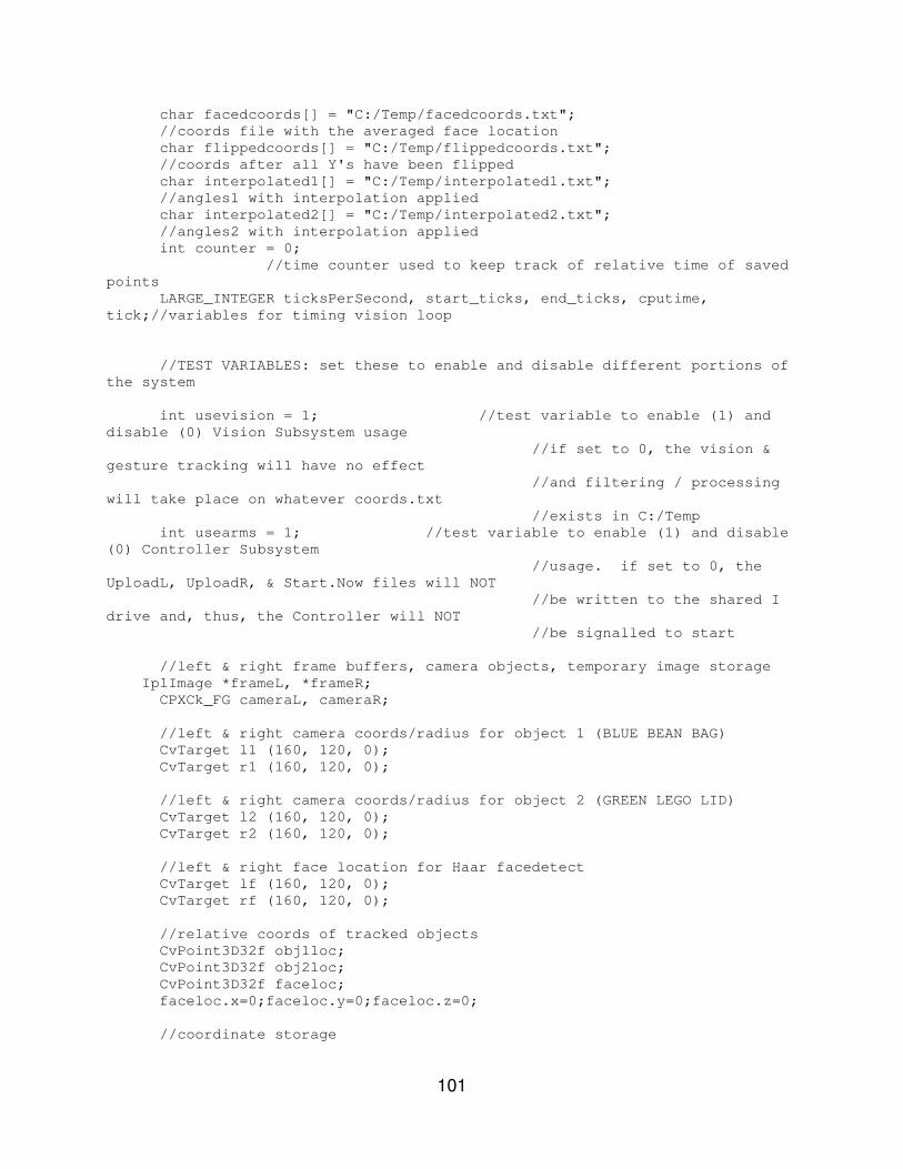
101
char facedcoords[] = "C:/Temp/facedcoords.txt";
//coords file with the averaged face location
char flippedcoords[] = "C:/Temp/flippedcoords.txt";
//coords after all Y's have been flipped
char interpolated1[] = "C:/Temp/interpolated1.txt";
//angles1 with interpolation applied
char interpolated2[] = "C:/Temp/interpolated2.txt";
//angles2 with interpolation applied
int counter = 0;
//time counter used to keep track of relative time of saved
points
LARGE_INTEGER ticksPerSecond, start_ticks, end_ticks, cputime,
tick;//variables for timing vision loop
//TEST VARIABLES: set these to enable and disable different portions of
the system
int usevision = 1; //test variable to enable (1) and
disable (0) Vision Subsystem usage
//if set to 0, the vision &
gesture tracking will have no effect
//and filtering / processing
will take place on whatever coords.txt
//exists in C:/Temp
int usearms = 1; //test variable to enable (1) and disable
(0) Controller Subsystem
//usage. if set to 0, the
UploadL, UploadR, & Start.Now files will NOT
//be written to the shared I
drive and, thus, the Controller will NOT
//be signalled to start
//left & right frame buffers, camera objects, temporary image storage
IplImage *frameL, *frameR;
CPXCk_FG cameraL, cameraR;
//left & right camera coords/radius for object 1 (BLUE BEAN BAG)
CvTarget l1 (160, 120, 0);
CvTarget r1 (160, 120, 0);
//left & right camera coords/radius for object 2 (GREEN LEGO LID)
CvTarget l2 (160, 120, 0);
CvTarget r2 (160, 120, 0);
//left & right face location for Haar facedetect
CvTarget lf (160, 120, 0);
CvTarget rf (160, 120, 0);
//relative coords of tracked objects
CvPoint3D32f obj1loc;
CvPoint3D32f obj2loc;
CvPoint3D32f faceloc;
faceloc.x=0;faceloc.y=0;faceloc.z=0;
//coordinate storage
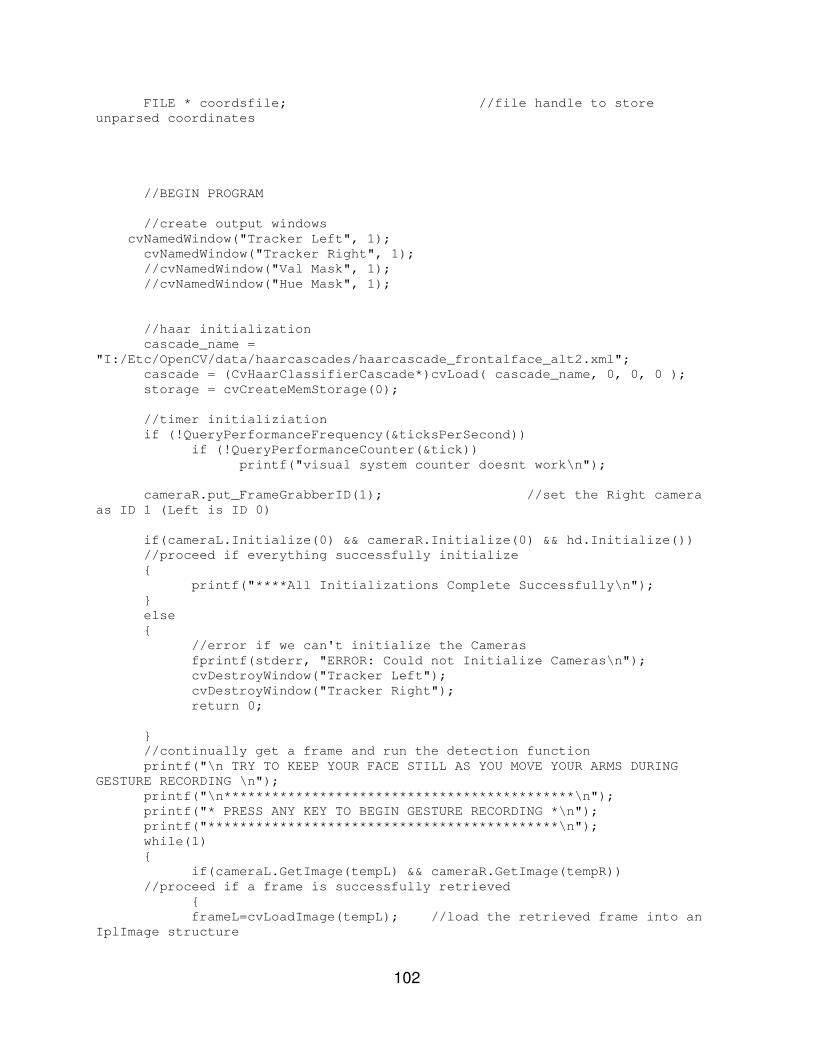
102
FILE * coordsfile; //file handle to store
unparsed coordinates
//BEGIN PROGRAM
//create output windows
cvNamedWindow("Tracker Left", 1);
cvNamedWindow("Tracker Right", 1);
//cvNamedWindow("Val Mask", 1);
//cvNamedWindow("Hue Mask", 1);
//haar initialization
cascade_name =
"I:/Etc/OpenCV/data/haarcascades/haarcascade_frontalface_alt2.xml";
cascade = (CvHaarClassifierCascade*)cvLoad( cascade_name, 0, 0, 0 );
storage = cvCreateMemStorage(0);
//timer initializiation
if (!QueryPerformanceFrequency(&ticksPerSecond))
if (!QueryPerformanceCounter(&tick))
printf("visual system counter doesnt work\n");
cameraR.put_FrameGrabberID(1); //set the Right camera
as ID 1 (Left is ID 0)
if(cameraL.Initialize(0) && cameraR.Initialize(0) && hd.Initialize())
//proceed if everything successfully initialize
{
printf("****All Initializations Complete Successfully\n");
}
else
{
//error if we can't initialize the Cameras
fprintf(stderr, "ERROR: Could not Initialize Cameras\n");
cvDestroyWindow("Tracker Left");
cvDestroyWindow("Tracker Right");
return 0;
}
//continually get a frame and run the detection function
printf("\n TRY TO KEEP YOUR FACE STILL AS YOU MOVE YOUR ARMS DURING
GESTURE RECORDING \n");
printf("\n********************************************\n");
printf("* PRESS ANY KEY TO BEGIN GESTURE RECORDING *\n");
printf("********************************************\n");
while(1)
{
if(cameraL.GetImage(tempL) && cameraR.GetImage(tempR))
//proceed if a frame is successfully retrieved
{
frameL=cvLoadImage(tempL); //load the retrieved frame into an
IplImage structure
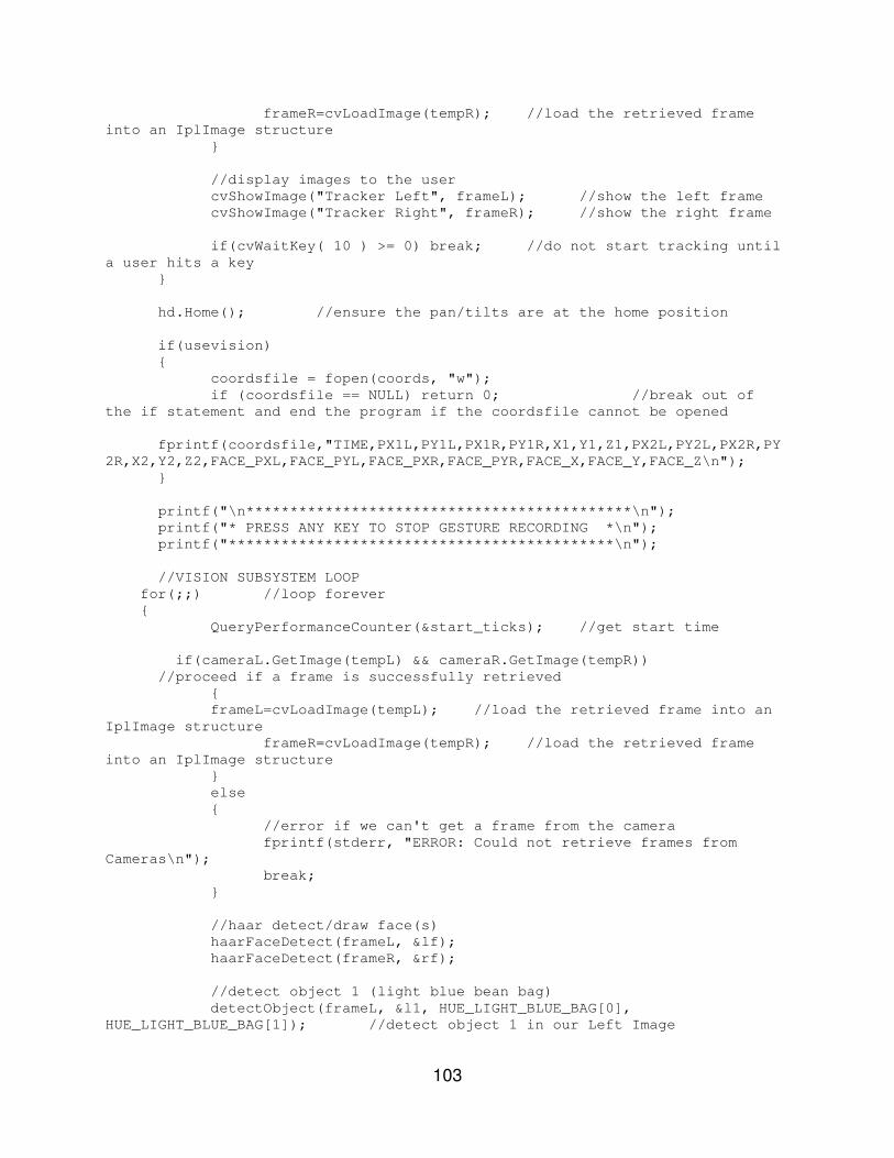
103
frameR=cvLoadImage(tempR); //load the retrieved frame
into an IplImage structure
}
//display images to the user
cvShowImage("Tracker Left", frameL); //show the left frame
cvShowImage("Tracker Right", frameR); //show the right frame
if(cvWaitKey( 10 ) >= 0) break; //do not start tracking until
a user hits a key
}
hd.Home(); //ensure the pan/tilts are at the home position
if(usevision)
{
coordsfile = fopen(coords, "w");
if (coordsfile == NULL) return 0; //break out of
the if statement and end the program if the coordsfile cannot be opened
fprintf(coordsfile,"TIME,PX1L,PY1L,PX1R,PY1R,X1,Y1,Z1,PX2L,PY2L,PX2R,PY
2R,X2,Y2,Z2,FACE_PXL,FACE_PYL,FACE_PXR,FACE_PYR,FACE_X,FACE_Y,FACE_Z\n");
}
printf("\n********************************************\n");
printf("* PRESS ANY KEY TO STOP GESTURE RECORDING *\n");
printf("********************************************\n");
//VISION SUBSYSTEM LOOP
for(;;) //loop forever
{
QueryPerformanceCounter(&start_ticks); //get start time
if(cameraL.GetImage(tempL) && cameraR.GetImage(tempR))
//proceed if a frame is successfully retrieved
{
frameL=cvLoadImage(tempL); //load the retrieved frame into an
IplImage structure
frameR=cvLoadImage(tempR); //load the retrieved frame
into an IplImage structure
}
else
{
//error if we can't get a frame from the camera
fprintf(stderr, "ERROR: Could not retrieve frames from
Cameras\n");
break;
}
//haar detect/draw face(s)
haarFaceDetect(frameL, &lf);
haarFaceDetect(frameR, &rf);
//detect object 1 (light blue bean bag)
detectObject(frameL, &l1, HUE_LIGHT_BLUE_BAG[0],
HUE_LIGHT_BLUE_BAG[1]); //detect object 1 in our Left Image

104
detectObject(frameR, &r1, HUE_LIGHT_BLUE_BAG[0],
HUE_LIGHT_BLUE_BAG[1]); //detect object 1 in our Right Image
//detect object 2 (green lego lid)
detectObject(frameL, &l2, HUE_BIG_GREEN_BALL[0],
HUE_BIG_GREEN_BALL[1]); //detect object 2 in our Left Image
detectObject(frameR, &r2, HUE_BIG_GREEN_BALL[0],
HUE_BIG_GREEN_BALL[1]); //detect object 2 in our Right Image
//draw Haar face on original image
drawTarget(frameL, lf, 2);
drawTarget(frameR, rf, 2);
//draw object 1 targets onto the original image
drawTarget(frameL, l1, 0);
drawTarget(frameR, r1, 0);
//draw object 2 targets onto the original image
drawTarget(frameL, l2, 7);
drawTarget(frameR, r2, 7);
//calculate relative XYZ depth
calculateXYZ(&obj1loc, l1, r1);
calculateXYZ(&obj2loc, l2, r2);
//print the coordinates to a text file
if (usevision)
fprintf(coordsfile,"%d,%d,%d,%d,%d,%f,%f,%f,%d,%d,%d,%d,%f,%f,%f,%d,%d,%d,%d,
%f,%f,%f\n",counter,l1.x,l1.y,r1.x,r1.y,obj1loc.x,obj1loc.y,obj1loc.z,l2.x,l2
.y,r2.x,r2.y,obj2loc.x,obj2loc.y,obj2loc.z,lf.x,lf.y,rf.x,rf.y,faceloc.x,face
loc.y,faceloc.z);
//display images to the user
cvShowImage("Tracker Left", frameL); //show the left frame
cvShowImage("Tracker Right", frameR); //show the right frame
if(cvWaitKey( 10 ) >= 0) break; //give the user a chance to
stop the tracking and continue with processing
counter++; //increment
the time counter
QueryPerformanceCounter(&end_ticks); //get stop time
//wait for a bit to ensure that each cycle takes a consistent 400
ms
while(((float)(end_ticks.QuadPart-
start_ticks.QuadPart)/ticksPerSecond.QuadPart*1000) < (float) VISION_TIME)
QueryPerformanceCounter(&end_ticks);
cputime.QuadPart = end_ticks.QuadPart - start_ticks.QuadPart;
//calculate the total time (should always be around VISION_TIME)
printf("detection time: %f\n",
(float)cputime.QuadPart/(float)ticksPerSecond.QuadPart*1000); //print out
how long it takes for detection cycle
}

105
//close the object coords file
if (usevision) fclose(coordsfile);
//PROCESSING SUBSYSTEM
//calculate the average face location and rewrite to file
avgFaceLoc(coords, facedcoords);
//flip the Y coordinate about it's average value to account for
upsidedown calculation
flipY(facedcoords,flippedcoords);
//Difference and Recursivly filter the set of XYZ coordinates stored in
C:/Temp/facedcoords.txt
//and save the results in C:/Temp/filteredcoords.txt
filterCoords(flippedcoords, tempcoords, filteredcoords);
//Filter for large changes in direction to compress the number of
points on the graph to as few
//as possible for simpler movement
compressCoords(filteredcoords, compressedcoords1, compressedcoords2);
//scale coords and rearrange axes for ISAC
fitCoordsToISAC2(compressedcoords1, fittedcoords1, RIGHT_ARM);
fitCoordsToISAC2(compressedcoords2, fittedcoords2, LEFT_ARM);
//calculate Joint Angles from Coordinates using Inverse Kinematics
calcJointAngles(fittedcoords1, angles1, RIGHT_ARM, END_EFF_NO,
SIMPLE_INV_KIN);
calcJointAngles(fittedcoords2, angles2, LEFT_ARM, END_EFF_NO,
SIMPLE_INV_KIN);
//interpolate angles between existing angles
interpolateAngles(angles1, interpolated1);
interpolateAngles(angles2, interpolated2);
//Open the joint angles file and upload the points to the shared I
drive
//to be read by the Neural Network Controller (located on another
computer: Octavia)
//angles2 goes to uploadL (left hand)
//angles1 goes to uploadR (right hand)
if (usearms) uploadToNNbatch(uploadL, uploadR, interpolated2,
interpolated1);
//Upload Start.Now file to indicate that the joint angles are ready and
//that the controller should begin execution
if (usearms) uploadGoFlag(goflag);
//create test points to be fed through the inverse kinematics based on
an expected workspace
//testSetForInverseKinematics(testfile, 400, 475, 50, 150, -90, 200,
5);
//create test set for forward kinematics to help find workspace

106
//testSetForForwardKinematics(testfile, 2*PI, 1);
//release our resources
//cvReleaseImage(&frameL);
//cvReleaseImage(&frameR);
//kill the results window
cvDestroyWindow("Tracker Left");
cvDestroyWindow("Tracker Right");
//cvDestroyWindow("Val Mask");
//cvDestroyWindow("Hue Mask");
return 0;
}
void detectObject(IplImage* img, CvTarget *tar, int low, int high)
{
//Temporary Images
IplImage* hsv = cvCreateImage(cvGetSize(img), 8, 3);
IplImage* hue = cvCreateImage(cvGetSize(img), 8, 1);
IplImage* sat = cvCreateImage(cvGetSize(img), 8, 1);
IplImage* val = cvCreateImage(cvGetSize(img), 8, 1);
IplImage* maskH = cvCreateImage(cvGetSize(img), 8, 1);
//IplImage* maskV = cvCreateImage(cvGetSize(img), 8, 1);
//IplImage* maskHV = cvCreateImage(cvGetSize(img), 8, 1);
//IplImage* blur = cvCreateImage(cvGetSize(img), 8, 3);
//IplImage* blur2 = cvCreateImage(cvGetSize(img), 8, 3);
IplConvKernel * selem =
cvCreateStructuringElementEx(3,3,1,1,CV_SHAPE_RECT); //kernel for use with
erode/dilate
//Send the image through a bilateral blur 3 times
//Bilateral tends to preserve edges
//cvSmooth(img, blur, CV_BILATERAL, 50, 3);
//cvSmooth(blur, blur2, CV_BILATERAL, 50, 3);
//cvSmooth(blur2, blur, CV_BILATERAL, 50, 3);
//Extract Hue/Sat/Val from BGR Image
cvCvtColor(img, hsv, CV_BGR2HSV);
//convert from BGR to HSV
cvSplit(hsv, hue, sat, val, 0);
//extract hue/sat/val channels
//Filter by Hue
cvInRangeS(hue, cvScalar(low), cvScalar(high), maskH); //filter by
Hue
cvErode(maskH,maskH,selem,3);
//Erode/Dilate maskH to eliminate noise
cvDilate(maskH, maskH, selem, 3);
//Filter by Value
//cvInRangeS(val, cvScalar(0), cvScalar(255), maskV); //filter by Value
//cvErode(maskV,maskV,selem,3);
//Erode maskV to elimniate noise

107
//create a combined Hue/Val mask
//cvZero(maskHV);
//cvCopy(maskH, maskHV, maskV);
//cvShowImage("Hue Mask", maskH);
//cvShowImage("Val Mask", maskV);
//Find the largest positive object
getConnectedComps(maskH /*maskHV*/,Comps);
//retrieve a list of all connected components in filtered image
if (comptot != 0)
{
//find largest component
maxcomp = 0;
maxarea = Comps[0]->area;
for (int j = 0; j < comptot; j++)
{
if (Comps[j]->area > maxarea)
{
maxarea = Comps[j]->area;
maxcomp = j;
}
}
//get center
tar->x = Comps[maxcomp]->rect.x + Comps[maxcomp]->rect.width/2;
tar->y = Comps[maxcomp]->rect.y + Comps[maxcomp]->rect.height/2;
//get radius
if (Comps[maxcomp]->rect.width > Comps[maxcomp]->rect.height)
tar->r = Comps[maxcomp]->rect.width/2;
else tar->r = Comps[maxcomp]->rect.height/2;
}
//Clean Up
cvReleaseStructuringElement(&selem);
cvReleaseImage(&hsv);
cvReleaseImage(&hue);
cvReleaseImage(&sat);
cvReleaseImage(&val);
cvReleaseImage(&maskH);
//cvReleaseImage(&maskV);
//cvReleaseImage(&maskHV);
//cvReleaseImage(&blur);
//cvReleaseImage(&blur2);
}
void drawTarget(IplImage *img, CvTarget obj, int clr)
{
if (obj.x <= img->width && obj.y <= img->height && clr < NUM_COLORS)
{
//draw a circle on the screen at the largest blobs center
location
cvCircle( img, obj, obj.r, COLORS[clr], 3, 8, 0 );
cvCircle( img, obj, 1, COLORS[clr], 3, 8, 0 );
}

108
}
//************************************************************************
//Authors: Jack Noble & Tom Billings
//Description: getConnectedComponents is used to distinguish between
foreground
// and background elements within the image. It does so by
rasterscanning the image
// for foreground pixels (pixel == 255) and numbers the areas
accordingly.
// If adjacent areas have the same numbers and are both foreground
or background pixels
// they are combined into one connected component. Only foreground
pixels are placed
// into Comps. If more than 20 components are found, a new Comps is
// initialized including old values.
//
//Variables:
// image is a binary image that has foreground and backgroun
elements
// Comps holds all of the data for the connected components found in
image
//
//Modified: by Sean Begley
// - replaced hard #s for img width/hight with soft
values retreived from
// passed in IplImage - 2/5/2008
//************************************************************************
void getConnectedComps(IplImage *image, CvConnectedComp ** Comps)
{
CvScalar pixval;
comptot = 0;
int CurrentCompVal = 0;
// used if need to reinitialize components array for more capacity
CvConnectedComp ** NewComp;
for (int j = 0; j < image->width*image->height; j++)
{
pixval = cvGet2D(image,j/image->width,j%image->width);
// if this pixel has the value of 255, this component has not yet
been recorded
if (pixval.val[0] > CurrentCompVal)
{
if (CurrentCompVal >= compmax)
Comps[CurrentCompVal] = new CvConnectedComp;
// fill this component in with the next lowest value
cvFloodFill(image,cvPoint(j%image->width,j/image-
>width),cvScalar(CurrentCompVal +
1),cvScalar(0),cvScalar(0),Comps[CurrentCompVal],4);
CurrentCompVal++;
// if at capacity reinitialize array to higher capacity
if (CurrentCompVal >= compcap)
{
NewComp = new CvConnectedComp*[compcap + 20];
for (int i = 0; i < CurrentCompVal; i++)
{
// copy component values into new array

109
NewComp[i] = new CvConnectedComp;
NewComp[i]->area = Comps[i]->area;
NewComp[i]->value.val[0] = Comps[i]-
>value.val[0];
NewComp[i]->rect = Comps[i]->rect;
// delete old values
delete Comps[i];
}
// update pointers and capacity
compcap = compcap + 20;
Comps = NewComp;
}
}
}
// update total number of components being used
comptot = CurrentCompVal;
// ensure total number of components ever used is up to date (for
deletion)
if (comptot > compmax)
compmax = comptot;
return;
}
//NOT USED
//if the object is far from the center move it a lot, close a medium, really
close, a small amount
void centerCams(int *lX, int *lY, int *rX, int *rY)
{
double pantilt[4]; //placeholder... real pantilt should be
global... but this function isnt used anymore
printf("%f\t%f\t%f\t%f\n",pantilt[0],pantilt[1],pantilt[2],pantilt[3]);
//left cam X (pan)
if (*lX < 80)
{ pantilt[0] = pantilt[0] + DELTA_B;}
else if (*lX >= 80 && *lX < 150)
{ pantilt[0] = pantilt[0] + DELTA_M;}
else if (*lX >= 150 && *lX < 158)
{ pantilt[0] = pantilt[0] + DELTA_S;}
//else if (*lX = 160) no change;
else if (*lX > 162 && *lX <= 170)
{ pantilt[0] = pantilt[0] - DELTA_S;}
else if (*lX > 170 && *lX < 240)
{ pantilt[0] = pantilt[0] - DELTA_M;}
else
{pantilt[0] = pantilt[0] - DELTA_B;}
//left cam Y (tilt)
if (*lY < 60)
{ pantilt[1] = pantilt[1] + DELTA_B;}
else if (*lY >= 60 && *lY < 110)
{ pantilt[1] = pantilt[1] + DELTA_M;}
else if (*lY >= 110 && *lY < 118)
{ pantilt[1] = pantilt[1] + DELTA_S;}
//else if (*lY = 120) no change;
else if (*lY >= 122 && *lY <= 130)
{ pantilt[1] = pantilt[1] - DELTA_S;}

110
else if (*lY >= 130 && *lY < 180)
{ pantilt[1] = pantilt[1] - DELTA_M;}
else
{pantilt[1] = pantilt[1] + DELTA_B;}
//right cam X (pan)
if (*rX < 80)
{ pantilt[2] = pantilt[2] + DELTA_B;}
else if (*rX >= 80 && *rX < 150)
{ pantilt[2] = pantilt[2] + DELTA_M;}
else if (*rX >= 150 && *rX < 158)
{ pantilt[2] = pantilt[2] + DELTA_S;}
//else if (*rX = 160) no change;
else if (*rX > 162 && *rX <= 170)
{ pantilt[2] = pantilt[2] - DELTA_S;}
else if (*rX > 170 && *rX < 240)
{pantilt[2] = pantilt[2] - DELTA_M;}
else
{pantilt[2] = pantilt[2] - DELTA_B;}
//right cam Y (tilt)
if (*rY < 60)
pantilt[3] = pantilt[3] + DELTA_B;
else if (*rY >= 60 && *rY < 110)
pantilt[3] = pantilt[3] + DELTA_M;
else if (*rY >= 110 && *rY < 118)
pantilt[3] = pantilt[3] + DELTA_S;
//else if (*rY = 120) no change;
else if (*rY >= 122 && *rY <= 130)
pantilt[3] = pantilt[3] - DELTA_S;
else if (*rY > 130 && *rY < 180)
pantilt[3] = pantilt[3] - DELTA_M;
else
pantilt[3] = pantilt[3] - DELTA_B;
//move cameras to center object on the screen
hd.MoveHead(pantilt);
//printf("%f\t%f\t%f\t%f\n\n",pantilt[0],pantilt[1],pantilt[2],pantilt[
3]);
}
//CAMERA TRANSFORM PARAMETERS
//center to camera base = 140mm (baseline = 280mm)
//camera base to rotation base = 91.948mm
//rotation base to camera = 65.5mm
//camera to focal point = 305.25mm
//sigma = 50 pixels per mm
//rotation about z is from dPan
//rotation about y if from dTilt
//effective picture elements: 768x494
//CCD sensing area: 6.4 x 4.8 mm
//currently gives the depth in some unknown unit... if at all...

111
//units are unknown, but the bueauty is that I dont care about units... I
just need relative motion.
//the plan is to take the relative motion of the tracked object, and scale it
to be as big as IASC
//can reasonably accomplish in his limited workspace
//may need to ensure that x,y,and z directions all have equal units (equal
rate of change of X Y Z coords
//relative to actual movement)
//to keep with the rest of the programming style, this should probably
void calculateXYZ(CvPoint3D32f *objloc, CvPoint left, CvPoint right)
{
double f = 15262.5; //focal length: 305.25 millimeters (50 px/mm) =
15262.5 px
double b = 14000; //base: millimeters (50 px/mm) = 14000 px
double sigma = 50; //pixels per mm
double xri = 0;
double xli = 0;
double yli = 0;
double yri = 0;
double z = 0;
double xr = 0;
double xl = 0;
double yr = 0;
double yl = 0;
double y = 0;
double x = 0;
double zft = 0;
double xft = 0;
double yft = 0;
//get pixel coords
xri = (double)right.x;
xli = (double)left.x;
yri = (double)right.y;
yli = (double)left.y;
//find z in weird units
z=f*b/((double)xli-(double)xri);
//calculate real y and x values in weird units
yr=yri*z/f;
yl=yli*z/f;
xr=xri*z/f;
xl=xli*z/f;
//average y
y=(yl+yr)/2;

112
//average x
x=(xr+xl)/2;
//write the values into the objloc to be returned
objloc->x=x;
objloc->y=y;
objloc->z=z;
//printf("%f\t%f\t%f\n",x,y,z);
}
//function to convert char array to double
//courtesy of a post by Narue at
http://www.daniweb.com/forums/thread80754.html
double to_double ( const char *p )
{
if (p == "") return NULL;
//else
std::stringstream ss ( p );
double result = 0;
ss>> result;
return result;
}
//Function that filters the XYZ coordinates in C:/Temp/coords.csv
//The filtering is accomplished by subtracting Z from X & Y then recursivly
filtering X & Y
//then subtracting the resultant X from Z and recursivly filtering Z. The
difference filtering
//(subtracting Z from X & Y and X from Z) is necessary to get rid of
artifacts that motion in the Z
//and X directions place in the other directions. The recursive filter is to
smooth the movement and
//get rid of noise.
void filterCoords(char coords[], char tempcoords[], char filteredcoords[])
{
FILE * coordsfile; //file handle to store
unparsed coordinates
FILE * filteredcoordsfile; //file handle to store
parsed/filtered coordinates
char line [512]; //holder for a single line of
coordsfile as it is parsed
char *token;
double* linearray = new double[22]; //array of
doubles to hold unfiltered values
double* currententry = new double[7]; //array to hold
values of the current entry (TIME,X1,Y1,Z1 X2,Y2,Z2)
double* historybuffer = new double[7]; //history buffer
for X&Y filtering (TIME,X1,Y1,Z1 X2,Y2,Z2)
double futurebuffer[5][7]; //future
buffer for Z filtering (TIME, X1, Y1, Z1, X2, Y2, Z2)
CvPoint3D32f faceloc; //holder
for location of the face

113
int counter=0; //counter for time keeping
int i,j; //random counters
//*******************************************************************
//******FILTER PASS 1 (DIFF FILTER & RECURSIVE FILTER of X & Y)******
//*******************************************************************
//GET FIRST ENTRY (line 2) FOR FILTERING HISTORY
//linearray guide
//[0]=TIME, [1]=PX1L, [2]=PY1L, [3]=PX1R, [4]=PY1R, [5]=X1, [6]=Y1,
[7]=Z1,
//[8]=PX2L, [9]=PY2L, [10]=PX2R, [11]=PY2R, [12]=X2, [13]=Y2, [14]=Z2,
[15]=FACE_PXL,
//[16]=FACE_PYL, [17]=FACE_PXR, [18]=FACE_PYR, [19]=FACE_X,
[20]=FACE_Y, [21]=FACE_Z
coordsfile = fopen(coords, "r"); //open coordsfile (to be filtered)
fgets(line, 512, coordsfile); //get 1st line to
ignore it b/c it is TITLES
if(fgets(line, 512, coordsfile) != NULL) //get a line from
coordsfile
{
//tokenize the line
i=0;
token=strtok(line, DELIM);
linearray[0] = to_double(token);
while((token=strtok(NULL, DELIM))!=NULL)
{
i++;
linearray[i]=to_double(token);
}
//copy important information into the history buffer
historybuffer[0] = linearray[0]; //TIME
historybuffer[1] = linearray[5]; //X1
historybuffer[2] = linearray[6]; //Y1
historybuffer[3] = linearray[7]; //Z1
historybuffer[4] = linearray[12]; //X2
historybuffer[5] = linearray[13]; //Y2
historybuffer[6] = linearray[14]; //Z2
//copy face X, Y, & Z
faceloc.x=linearray[19];
faceloc.y=linearray[20];
faceloc.z=linearray[21];
//filter faceloc using the same difference filter equation as the
other points
faceloc.x = faceloc.x - faceloc.z*XY_DIFF; //X=X-Z*0.008
faceloc.y = faceloc.y - faceloc.z*XY_DIFF; //Y=Y-Z*0.008
faceloc.z = faceloc.z/Z_SCALE - faceloc.x; //Z=Z/40-X
}
fclose(coordsfile);
114
//start back at the beginning
coordsfile = fopen(coords, "r");
//open coordsfile (to be filtered)
filteredcoordsfile = fopen(tempcoords, "w"); //open
filteredcoordsfile (to hold filtered coords)
fprintf(filteredcoordsfile,"TIME,X1,Y1,Z1,X2,Y2,Z2\n");
//print titles for filteredcoordsfile
fgets(line, 512, coordsfile);
//ignore 1st line of coordsfile b/c it is TITLES
counter=0;
while(1) //loop forever
{
if(fgets(line, 512, coordsfile) != NULL) //get a line for
coordsfile
{
//GET NEXT LINE
//tokenize the line
i=0;
token=strtok(line, DELIM);
linearray[0] = to_double(token);
while((token=strtok(NULL, DELIM))!=NULL)
{
i++;
linearray[i]=to_double(token);
}
//DIFFERENCE FILTER X & Y
//find Xdiff & Ydiff (Xdiff[i]=X[i]-Z[i]*.008) and save to
filteredcoords
//currententry guide
//[0]=TIME, [1]=Xdiff1, [2]=Ydiff1, [3]=Z1, [4]=Xdiff2,
[5]=Ydiff2, [6]=Z2
currententry[0] = linearray[0];
//TIME = TIME
currententry[1] = linearray[5] - linearray[7]*XY_DIFF;
//Xdiff1=X1-Z1*0.008
currententry[2] = linearray[6] - linearray[7]*XY_DIFF;
//Ydiff1=Y1-Z1*0.008
currententry[3] = linearray[7];
//Z1 = Z1
currententry[4] = linearray[12] - linearray[14]*XY_DIFF;
//Xdiff2=X2-Z2*0.008
currententry[5] = linearray[13] - linearray[14]*XY_DIFF;
//Ydiff2=Y2-Z2*0.008;
currententry[6] = linearray[14];
//Z2 = Z2
//RECURSIVE FILTER X & Y
//calculate X_rec_diff & Y_rec_diff
(X_rec_diff[i]=0.2*Xdiff[i]+0.8*X_rec_diff[i-1])
//currententry guide
//[0]=TIME, [1]=X_rec_diff1, [2]=Y_rec_diff1, [3]=Z1,
[4]=X_rec_diff2, [5]=Y_rec_diff2, [6]=Z2
/*
if (counter < 1)
{

115
currententry[1] = currententry[1];
//recursivly filter X1
currententry[2] = currententry[2];
//recursivly filter Y1
currententry[4] = currententry[4];
//recursivly filter X2
currententry[5] = currententry[5];
//recursivly filter Y2
}
else
{
currententry[1] = A0*currententry[1] +
B0*historybuffer[1]; //recursivly filter X1
currententry[2] = A0*currententry[2] +
B0*historybuffer[2]; //recursivly filter Y1
currententry[4] = A0*currententry[4] +
B0*historybuffer[4]; //recursivly filter X2
currententry[5] = A0*currententry[5] +
B0*historybuffer[5]; //recursivly filter Y2
}
*/
//UPDATE HISTORYBUFFER
for(j=0;j<7;j++)
{
historybuffer[j]=currententry[j];
}
//PRINT LINE TO FILE
for(i=0;i<6;i++)
{
fprintf(filteredcoordsfile, "%f,", currententry[i]);
}
fprintf(filteredcoordsfile, "%f\n", currententry[6]);
}
else //if we reach the end of the file break out of the
while loop
{
//close files
fclose(coordsfile);
fclose(filteredcoordsfile);
break;
}
counter++;
}
printf ("****Filter PASS 1 Complete\n");
//**************************************************************
//******FILTER PASS 2 (DIFFERENCE & RECURSIVE FILTER of Z)******
//**************************************************************
//FILL FUTURE BUFFER (lines 2-6) FOR FILTERING
coordsfile = fopen(tempcoords, "r"); //open coordsfile (to be
filtered)
fgets(line, 512, coordsfile); //get 1st line to
ignore it b/c it is TITLES

116
for(i=0;i<5;i++)
{
if(fgets(line, 512, coordsfile) != NULL) //get a line from
coordsfile
{
//tokenize the line
j=0;
token=strtok(line, DELIM);
currententry[0] = to_double(token);
while((token=strtok(NULL, DELIM))!=NULL)
{
j++;
currententry[j]=to_double(token);
}
//copy important information into the future buffer
futurebuffer[i][0] = currententry[0]; //TIME
futurebuffer[i][1] = currententry[1]; //X1
futurebuffer[i][2] = currententry[2]; //Y1
futurebuffer[i][3] = currententry[3]; //Z1
futurebuffer[i][4] = currententry[4]; //X2
futurebuffer[i][5] = currententry[5]; //Y2
futurebuffer[i][6] = currententry[6]; //Z2
}
}
//FILL HISTORY BUFFER & CURRENT ENTRY
for(i=0;i<7;i++)
{
historybuffer[i]=futurebuffer[0][i];
currententry[i]=futurebuffer[0][i];
}
filteredcoordsfile = fopen(filteredcoords, "w");
//open filteredcoordsfile2 (to hold filtered coords)
fprintf(filteredcoordsfile,"TIME,X1,Y1,Z1,X2,Y2,Z2,XF,YF,ZF\n");
//print titles for filteredcoordsfile
counter=0;
while(1) //loop forever
{
if(fgets(line, 512, coordsfile) != NULL) //get a line for
coordsfile
{
//UPDATE CURRENTENTRY
for(i=0;i<7;i++)
{
currententry[i]=futurebuffer[0][i];
}
//UPDATE FUTUREBUFFER
for(i=0;i<4;i++)
{
for(j=0;j<7;j++)
{
futurebuffer[i][j]=futurebuffer[i+1][j];

117
}
}
//GET NEXT LINE
//tokenize the line
j=0;
token=strtok(line, DELIM);
futurebuffer[4][0] = to_double(token);
while((token=strtok(NULL, DELIM))!=NULL)
{
j++;
futurebuffer[4][j]=to_double(token);
}
//DIFFERENCE FILTER Z: find Zdiff (Zdiff[i]=Z[i]/40-
X_rec_diff[i+5])
//currententry guide
//[0]=TIME, [1]=Xdiff1, [2]=Ydiff1, [3]=Z1, [4]=Xdiff2,
[5]=Ydiff2, [6]=Z2
currententry[0] = currententry[0]; //TIME = TIME
currententry[1] = currententry[1]; //X1 = X1
currententry[2] = currententry[2]; //Y1 = Y1
currententry[3] = currententry[3]/Z_SCALE -
futurebuffer[0][1];
currententry[4] = currententry[4]; //X2 = X2
currententry[5] = currententry[5]; //Y2 = Y2
currententry[6] = currententry[6]/Z_SCALE -
futurebuffer[0][4];
//RECURSIVE FILTER Z: calculate Z_rec_diff
(Z_rec_diff[i]=0.2*Zdiff[i]+0.8*Z_rec_diff[i-1])
//currententry guide
//[0]=TIME, [1]=X_rec_diff1, [2]=Y_rec_diff1, [3]=Z1,
[4]=X_rec_diff2, [5]=Y_rec_diff2, [6]=Z2
if(counter < 1) //special case for 1st value b/c there is
no history
{
currententry[3]=currententry[3]; //no filter
currententry[6]=currententry[6]; //no filter
}
else
{
currententry[3]=A0*currententry[3]+B0*historybuffer[3];
//recursivly filter Z1
currententry[6]=A0*currententry[6]+B0*historybuffer[6];
//recursivly filter Z2
}
//UPDATE HISTORYBUFFER
for(i=0;i<7;i++)
{
historybuffer[i]=currententry[i];
}
//PRINT LINE TO FILE

118
for(i=0;i<7;i++)
{
fprintf(filteredcoordsfile, "%f,", currententry[i]);
}
fprintf(filteredcoordsfile, "%f,%f,%f\n",
faceloc.x,faceloc.y,faceloc.z);
}
else //if we reach the end of the file break out of the
while loop
{
//FINISH FILTER ON LAST 5 ENTRIES (held in futurebuffer)
for(i=0;i<5;i++)
{
//difference filter
currententry[0] = futurebuffer[i][0];
//TIME = TIME
currententry[1] = futurebuffer[i][1];
//X1 = X1;
currententry[2] = futurebuffer[i][2];
//Y1 = Y1
currententry[3] = futurebuffer[i][3]/Z_SCALE -
futurebuffer[i][1]; //diff filter Z1
currententry[4] = futurebuffer[i][4];
//X2 = X2
currententry[5] = futurebuffer[i][5];
//Y2 = Y2
currententry[6] = futurebuffer[i][6]/Z_SCALE -
futurebuffer[i][4]; //diff filter Z1
//recursive filter
currententry[3]=A0*currententry[3]+B0*historybuffer[3];
//recursivly filter Z1
currententry[6]=A0*currententry[6]+B0*historybuffer[6];
//recursivly filter Z2
//update history buffer
for(j=0;j<7;j++)
{
historybuffer[j]=currententry[j];
}
//print line to file
for(j=0;j<7;j++)
{
fprintf(filteredcoordsfile, "%f,",
currententry[j]);
}
fprintf(filteredcoordsfile, "%f,%f,%f\n",
faceloc.x,faceloc.y,faceloc.z);
}
//close files
fclose(coordsfile);
fclose(filteredcoordsfile);
break;

119
}
counter++;
}
printf ("****Filter PASS 2 Complete\n");
printf ("****All Filtering Complete\n");
//cleanup
delete[] linearray;
delete[] currententry;
delete[] historybuffer;
}
//function to reduce a set of points down to as few pnts as possible while
still maintaining the basic flow
//ie: a sine wave of many points would become a triangle wave with points
only at the positive and negative peaks
//this function also splits the single coords file into 2 compressed coords
files so that the fitting function
//can fit the left and right arms maximally and individually. This splitting
should probably be done in a seperate
//function
void compressCoords(char coords[], char compressedcoords1[], char
compressedcoords2[])
{
FILE * coordsfile; //file handle to store
unparsed coordinates
FILE * compressedcoordsfile1; //file handle to store parsed/compressed
1 coordinates (TIME, X1, Y1, Z1)
FILE * compressedcoordsfile2; //file handle to store parsed/compressed
2 coordinates (TIME, X2, Y2, Z2)
char line [512]; //holder for a single line of
coordsfile as it is parsed
char *token;
double* linearray = new double[10]; //array to hold
input line
double* lastpoint = new double[7]; //array to hold
values of the last saved point (TIME,X1,Y1,Z1 X2,Y2,Z2)
double* currpoint = new double[7]; //array to hold
values of the current point (TIME,X1,Y1,Z1 X2,Y2,Z2)
double* lastsavedpoint1 = new double[4]; //array to hold values
of the last saved point for obj 1 (TIME, X1, Y1, Z1)
double* lastsavedpoint2 = new double[4]; //array to hold values
of the last saved point for obj 2 (TIME, X2, Y2, Z2);
double* lastinterimpoint1 = new double[4]; //array to hold
values of the last interrmediate point for obj 1 (TIME, X1, Y1, Z1)
double* lastinterimpoint2 = new double[4]; //array to hold
values of the last interrmediate point for obj 2 (TIME, X2, Y2, Z2);
double* pointdiff = new double[7]; //array to hold
the difference of a point and its predecessor (N/A,X1,Y1,Z1 X2,Y2,Z2)
int* direction = new int[7]; //array to hold
the direction of motion for each axis of each object (-1 = down, +1 = up, 0 =
undefined/equal) (X1,Y1,Z1 X2,Y2,Z2)
int* tempdir = new int[7]; //array to
hold the direction of motion for each axis of each object (-1 = down, +1 =
up, 0 = undefined/equal) (X1,Y1,Z1 X2,Y2,Z2)
120
//NOTE: in pointdiff, direction, and tempdir, the 1st element is
ignored and exists only to keep everything simple with regards to the 7
element point arrays
int changeflag1 = 0; //flag to
indicate a change in direction in obj1
int changeflag2 = 0; //flag to
indicate a change in direction in obj2
int i;
//random counters
//FILTER FOR CHANGE IN DIRECTION
coordsfile = fopen(coords, "r");
//open coordsfile (to be compressed)
compressedcoordsfile1 = fopen(compressedcoords1, "w");
//open compressedcoordsfile1 (to hold compressed obj1 coords)
compressedcoordsfile2 = fopen(compressedcoords2, "w");
//open compressedcoordsfile2 (to hold compressed obj2 coords)
fprintf(compressedcoordsfile1,"TIME,X1,Y1,Z1,XF,YF,ZF\n"); //print
titles for compressedcoordsfile1
fprintf(compressedcoordsfile2,"TIME,X2,Y2,Z2,XF,YF,ZF\n"); //print
titles for compressedcoordsfile2
fgets(line, 512, coordsfile);
//ignore 1st line of coordsfile b/c it is TITLES
//get 1st point, add it to results, save it as last point & last saved
points
if(fgets(line, 512, coordsfile) != NULL) //get a line from
coordsfile
{
//tokenize the line
i=0;
token=strtok(line, DELIM);
linearray[0] = to_double(token);
while((token=strtok(NULL, DELIM))!=NULL)
{
i++;
linearray[i]=to_double(token);
}
//save lastpoint
for(i=0;i<7;i++)
{
lastpoint[i]=linearray[i];
}
//print to compressed coords files & save to lastsavedpoint &
lastinterimpoint
fprintf(compressedcoordsfile1, "%f,", lastpoint[0]);
fprintf(compressedcoordsfile2, "%f,", lastpoint[0]);
lastsavedpoint1[0]=lastpoint[0];
lastsavedpoint2[0]=lastpoint[0];
lastinterimpoint1[0]=lastpoint[0];
for(i=1;i<3;i++)
{
fprintf(compressedcoordsfile1, "%f,", lastpoint[i]);
fprintf(compressedcoordsfile2, "%f,", lastpoint[i+3]);
lastsavedpoint1[i]=lastpoint[i];
121
lastinterimpoint1[i]=lastpoint[i];
lastsavedpoint2[i]=lastpoint[i+3];
}
fprintf(compressedcoordsfile1, "%f,%f,%f,%f\n",
lastpoint[3],linearray[7],linearray[8],linearray[9]);
fprintf(compressedcoordsfile2, "%f,%f,%f,%f\n",
lastpoint[6],linearray[7],linearray[8],linearray[9]);
lastsavedpoint1[3]=lastpoint[3];
lastinterimpoint1[3]=lastpoint[3];
lastsavedpoint2[3]=lastpoint[6];
}
//get 2nd point, save it as currpoint, and establish directions
if(fgets(line, 512, coordsfile) != NULL) //get a line from
coordsfile
{
//tokenize the line
i=0;
token=strtok(line, DELIM);
linearray[0] = to_double(token);
while((token=strtok(NULL, DELIM))!=NULL)
{
i++;
linearray[i]=to_double(token);
}
//save currpoint
for(i=0;i<7;i++)
{
currpoint[i]=linearray[i];
}
//set directions
for(i=1;i<7;i++)
{
pointdiff[i] = currpoint[i] - lastpoint[i];
if (pointdiff[i] > 0){ direction[i] = 1; }
else if (pointdiff[i] < 0){ direction[i] = -1; }
else { direction[i] = 0; }
}
}
while(1) //loop forever
{
//update last point
for(i=0;i<7;i++)
{
lastpoint[i]=currpoint[i];
}
//get new currpoint
if(fgets(line, 512, coordsfile) != NULL) //get a line from
coordsfile
{
//tokenize the line

122
i=0;
token=strtok(line, DELIM);
linearray[0] = to_double(token);
while((token=strtok(NULL, DELIM))!=NULL)
{
i++;
linearray[i]=to_double(token);
}
//save currpoint
for(i=0;i<7;i++)
{
currpoint[i]=linearray[i];
}
//get tempdir
for(i=1;i<7;i++)
{
pointdiff[i] = currpoint[i] - lastpoint[i];
if (pointdiff[i] > 0){ tempdir[i] = 1; }
else if (pointdiff[i] < 0){ tempdir[i] = -1; }
else { tempdir[i] = 0; }
}
//check for changes in direction for object 1
for(i=1;i<3;i++) //ignore Z (4)
{
if (tempdir[i] != direction[i])
{
//ensure that the magnitude
if(abs(currpoint[i]-lastsavedpoint1[i]) > 1000)
changeflag1 = 1;
}
}
//check for changes in direction for object 2
for(i=4;i<6;i++) //ignore Z (7)
{
if (tempdir[i] != direction[i])
{
//ensure that the magnitude
if(abs(currpoint[i]-lastsavedpoint2[i-3]) >
1000) changeflag2 = 1;
}
}
//if a change in direction in obj1 has occurred, print &
save the point
if (changeflag1)
{
//print to compressed coords files & save the point
fprintf(compressedcoordsfile1, "%f,", lastpoint[0]);
lastsavedpoint1[0] = lastpoint[0];
lastinterimpoint1[0] = lastpoint[0];
for(i=1;i<3;i++)
{

123
fprintf(compressedcoordsfile1, "%f,",
lastpoint[i]);
lastsavedpoint1[i] = lastpoint[i];
lastinterimpoint1[i] = lastpoint[i];
}
fprintf(compressedcoordsfile1, "%f,%f,%f,%f\n",
lastpoint[3],linearray[7],linearray[8],linearray[9]);
lastsavedpoint1[3] = lastpoint[3];
lastinterimpoint1[3] = lastpoint[3];
}
//there is no change in direction BUT it has been more then
4 points since our last save, save one
/*
else if(lastpoint[0] - lastinterimpoint1[0] > 4)
{
//print to compressed coords files & save the point
fprintf(compressedcoordsfile1, "%f,", lastpoint[0]);
lastinterimpoint1[0] = lastpoint[0];
for(i=1;i<3;i++)
{
fprintf(compressedcoordsfile1, "%f,",
lastpoint[i]);
lastinterimpoint1[i] = lastpoint[i];
}
fprintf(compressedcoordsfile1, "%f,%f,%f,%f\n",
lastpoint[3],linearray[7],linearray[8],linearray[9]);
lastinterimpoint1[3] = lastpoint[3];
}
*/
//if a change in direction in obj2 has occurred, print &
save the point
if (changeflag2)
{
//print to compressed coords files & save the point
fprintf(compressedcoordsfile2, "%f,", lastpoint[0]);
lastsavedpoint2[0] = lastpoint[0];
for(i=4;i<6;i++)
{
fprintf(compressedcoordsfile2, "%f,",
lastpoint[i]);
lastsavedpoint2[i-3] = lastpoint[i];
}
fprintf(compressedcoordsfile2, "%f,%f,%f,%f\n",
lastpoint[6],linearray[7],linearray[8],linearray[9]);
lastsavedpoint2[3] = lastpoint[6];
}
//there is no change in direction BUT it has been more then
4 points since our last save, save one
/*
else if(lastpoint[0] - lastinterimpoint1[0] > 4)
{
//print to compressed coords files & save the point
fprintf(compressedcoordsfile2, "%f,", lastpoint[0]);

124
lastinterimpoint2[0] = lastpoint[0];
for(i=4;i<6;i++)
{
fprintf(compressedcoordsfile2, "%f,",
lastpoint[i]);
lastinterimpoint2[i] = lastpoint[i];
}
fprintf(compressedcoordsfile2, "%f,%f,%f,%f\n",
lastpoint[6],linearray[7],linearray[8],linearray[9]);
lastinterimpoint2[3] = lastpoint[6];
}
*/
//reset changeflags
changeflag1 = 0;
changeflag2 = 0;
//update directions
for(i=0;i<7;i++)
{
direction[i] = tempdir[i];
}
}
else //if we reach the end of the file break out of the
while loop
{
//print the last point
fprintf(compressedcoordsfile1, "%f,", currpoint[0]);
fprintf(compressedcoordsfile2, "%f,", currpoint[0]);
for(i=1;i<3;i++)
{
fprintf(compressedcoordsfile1, "%f,", currpoint[i]);
fprintf(compressedcoordsfile2, "%f,",
currpoint[i+3]);
}
fprintf(compressedcoordsfile1, "%f,%f,%f,%f\n",
lastpoint[3],linearray[7],linearray[8],linearray[9]);
fprintf(compressedcoordsfile2, "%f,%f,%f,%f\n",
lastpoint[6],linearray[7],linearray[8],linearray[9]);
//close files
fclose(coordsfile);
fclose(compressedcoordsfile1);
fclose(compressedcoordsfile2);
break;
}
}
printf ("****Compression Complete\n");
//cleanup
delete[] lastpoint;
delete[] currpoint;
delete[] lastsavedpoint1;
delete[] lastsavedpoint2;

125
delete[] pointdiff;
delete[] direction;
delete[] tempdir;
delete[] linearray;
}
//courtesy of http://www.functionx.com/cpp/examples/abs.htm
double abs(double Nbr)
{
// return (Nbr >= 0) ? Nbr : -Nbr;
if( Nbr >= 0 )
return Nbr;
else
return -Nbr;
}
//function that takes compressed coords, and uploads them to a shared drive
location for use by
//the neural network controller. This is done one point at a time so that
only 1 point is available
//to the NN Controller at a time
void uploadToNN1by1(char uploadL[], char uploadR[], char coordsL[], char
coordsR[])
{
int counter = 0; //counter
char lineL [512]; //holder for a
single line of coordsfileL as it is parsed
char lineR [512]; //holder for a
single line of coordsfileR as it is parsed
char *token; //holder
for tokenizing line
char *Lout; //flag to
see if we've reached the end of the file
char *Rout; //flag to
see if we've reached the end of the file
int i;
//random counter variable
int updateL = 1; //flag to see if
the point has been uploaded yet
int updateR = 1; //flag to see if
the point has been uploaded yet
double* currpointL = new double[4]; //array to hold values
of the current point (TIME,X1,Y1,Z1)
double* currpointR = new double[4]; //array to hold values
of the current point (TIME,X2,Y2,Z2)
FILE *uploadfileL; //file
handle for temp upload file to send info to the NN L
FILE *uploadfileR; //file
handle for temp upload file to send info to the NN R
FILE *coordsfileL; //file
handle for coords to be uploaded L
FILE *coordsfileR; //file
handle for coords to be uploaded R
//open coords files
coordsfileL = fopen(coordsL, "r"); //coordinates to be uploaded
coordsfileR = fopen(coordsR, "r"); //coordinates to be uploaded

126
fgets(lineL, 512, coordsfileL); //ignore 1st line of TITLES
fgets(lineR, 512, coordsfileR); //ignore 1st line of TITLES
//cycle through a loop where each cycle represents 1 "timestep" from
the input process
//new coordinates will only be uploaded at the appropriate timestep to
maintain the spacing
for(;;)
{
//get lines from LEFT and RIGHT coordsfiles
if (updateL == 1) Lout = fgets(lineL, 512, coordsfileL);
if (updateR == 1) Rout = fgets(lineR, 512, coordsfileR);
updateL = 0;
updateR = 0;
if(Lout != NULL || Rout != NULL)
{
//tokenize the LEFT line
i=0;
token=strtok(lineL, DELIM);
currpointL[0] = to_double(token);
while((token=strtok(NULL, DELIM))!=NULL)
{
i++;
currpointL[i]=to_double(token);
}
//tokenize the RIGHT line
i=0;
token=strtok(lineR, DELIM);
currpointR[0] = to_double(token);
while((token=strtok(NULL, DELIM))!=NULL)
{
i++;
currpointR[i]=to_double(token);
}
//if TIME (from currpoint) is equal to or less then the
current iteration of the loop, upload it
if (lineL != NULL && currpointL[0] <= counter)
{
//upload the current time (NN receiver will check to
see if a new point has come in by comparing
//the timestamp with it's last saved timestamp)
uploadfileL = fopen(uploadL, "w");
fprintf(uploadfileL, "%f,%f,%f,%f\n", currpointL[0],
currpointL[1], currpointL[2], currpointL[3]);
fclose(uploadfileL);
updateL = 1;
}
if (lineR != NULL && currpointR[0] <= counter)
{
//upload the current time (NN receiver will check to
see if a new point has come in by comparing

127
//the timestamp with it's last saved timestamp)
uploadfileR = fopen(uploadR, "w");
fprintf(uploadfileR, "%f,%f,%f,%f\n", currpointR[0],
currpointR[1], currpointR[2], currpointR[3]);
fclose(uploadfileR);
updateR = 1;
}
}
else break; //if we've reached the end of both files, break
out of the loop
Sleep(1000); //sleep for a time representative of the delay
between 2 timesteps (Sleep takes milliseconds as an argument)
counter++; //update counter
}
fclose(coordsfileL);
fclose(coordsfileR);
//cleanup
delete[] currpointL;
delete[] currpointR;
}
//function that takes compressed coords, and uploads them to a shared drive
location for use by
//the neural network controller. It gives all the points the NN Controller
and requires that the NN
//cut them apart and use the points in order.
void uploadToNNbatch(char uploadL[], char uploadR[], char coordsL[], char
coordsR[])
{
char line [512]; //holder for a
single line of a coordsfile as it is parsed
FILE *uploadfileL; //file
handle for temp upload file to send info to the NN L
FILE *uploadfileR; //file
handle for temp upload file to send info to the NN R
FILE *coordsfileL; //file
handle for coords to be uploaded L
FILE *coordsfileR; //file
handle for coords to be uploaded R
//open coords files
coordsfileL = fopen(coordsL, "r"); //coordinates to be uploaded
coordsfileR = fopen(coordsR, "r"); //coordinates to be uploaded
//fgets(line, 512, coordsfileL); //ignore 1st line of TITLES
//fgets(line, 512, coordsfileR); //ignore 1st line of TITLES
uploadfileL = fopen(uploadL, "w");
uploadfileR = fopen(uploadR, "w");
//copy all but the 1st line to a text file on the shared I drive for
use by the Neural Network Controller
for(;;)
{
if(fgets(line, 512, coordsfileL) != NULL)
{

128
fprintf(uploadfileL, line);
}
else break; //if we've reached the end of the file, break
out of the loop
}
for(;;)
{
if(fgets(line, 512, coordsfileR) != NULL)
{
fprintf(uploadfileR, line);
}
else break; //if we've reached the end of the file, break
out of the loop
}
printf ("****Upload to Controller Complete\n");
fclose(uploadfileL);
fclose(uploadfileR);
fclose(coordsfileL);
fclose(coordsfileR);
}
//function to convert the points from their current magic scale to a scale
suitable for ISAC's NN Controller
//also switch axes: X->Y, Y->Z, Z->X
//also, if necessary, mirror image X->Y axis for mirrored motion
void fitCoordsToISAC(char coords[], char fittedcoords[])
{
FILE *coordsfile; //file handle for
coords to be uploaded
FILE *fittedcoordsfile; //file handle for
the newley fittted coords
int i,j;
char line [512]; //holder for a
single line of a coordsfile as it is parsed
double* linearray = new double[7]; //array to values hold
a line of coordsfile
double* currpoint = new double[4]; //array to hold values
of the current point (TIME,X1,Y1,Z1)
double* modpoint = new double[4]; //array to hold values
of the current point modified (TIME,X1,Y1,Z1)
double maxs[2][4]; //2D array to hold max values [0][i]=N/A,
X max TIME, Y max TIME, Z max TIME
//
[1][i]=N/A, X max, Y max, Z max
double mins[2][4]; //2D array to hold min values [0][i]=N/A,
X min TIME, Y min TIME, Z min TIME
//
[1][i]=N/A, X min, Y min, Z min
double diffs[4]; //array to hold maxs[1][i] - mins[1][i]
double divs[4]; //array to hold diffs/(ISAC_MAX-
ISAC_MIN);
double shift[4]; //array to hold shift factors;
char *token;

129
//initialize maxs/mins
for(i=0;i<2;i++)
{
for(j=0;j<4;j++)
{
maxs[i][j]=-999999999999;
mins[i][j]=999999999999;
}
}
//GET MAX AND MIN FOR X, Y, Z
//open coords files
coordsfile = fopen(coords, "r"); //coordinates to be parsed
fgets(line, 512, coordsfile); //ignore 1st line of TITLES
for(;;)
{
if(fgets(line, 512, coordsfile) != NULL) //get a line from
coordsfile
{
//tokenize the line
i=0;
token=strtok(line, DELIM);
linearray[0] = to_double(token);
while((token=strtok(NULL, DELIM))!=NULL)
{
i++;
linearray[i]=to_double(token);
}
//save to currpoint
for(i=0;i<4;i++)
{
currpoint[i]=linearray[i];
}
//find max/mins
for(i=1;i<4;i++)
{
if(currpoint[i] >= maxs[1][i])
{
maxs[0][i] = currpoint[0]; //set new max
time
maxs[1][i] = currpoint[i]; //set new max
value
}
if(currpoint[i] <= mins[1][i])
{
mins[0][i] = currpoint[0]; //set new min
time
mins[1][i] = currpoint[i]; //set new min
value
}
}
}
else

130
{
fclose(coordsfile);
break; //if we've reached the end of the file,
break out of the loop
}
}
//CALCULATE DIFFERENCES
for(i=1;i<4;i++)
{
diffs[i]=maxs[1][i]-mins[1][i]; //get the range of each
axes
}
//DIVIDE DIFFERENCE BY ISAC'S RANGE
divs[1]=diffs[1]/(ISAC_Y_MAX-ISAC_Y_MIN); //our X is ISACs Y
divs[2]=diffs[2]/(ISAC_Z_MAX-ISAC_Z_MIN); //our Y is ISACs Z
divs[3]=diffs[3]/(ISAC_X_MAX-ISAC_X_MIN); //our Z is ISACs X
//CALCULATE SHIFT FACTOR
shift[1]=(mins[1][1]/divs[1]-ISAC_Y_MIN)*-1;
shift[2]=(mins[1][2]/divs[2]-ISAC_Z_MIN)*-1;
shift[3]=(mins[1][3]/divs[3]-ISAC_X_MIN)*-1;
//REWRITE FILE LINE BY LINE APPLYING SCALE/SHIFT AND REARRANGING AXES
coordsfile = fopen(coords, "r"); //coordinates to
be parsed
fittedcoordsfile = fopen(fittedcoords, "w"); //fitted coordinates
file
fgets(line, 512, coordsfile); //ignore 1st line
of TITLES
for(;;)
{
if(fgets(line, 512, coordsfile) != NULL) //get a line from
coordsfile
{
//tokenize the line
i=0;
token=strtok(line, DELIM);
linearray[0] = to_double(token);
while((token=strtok(NULL, DELIM))!=NULL)
{
i++;
linearray[i]=to_double(token);
}
//save to currpoint
for(i=0;i<4;i++)
{
currpoint[i]=linearray[i];
}
modpoint[0]=currpoint[0];
for(i=1;i<4;i++)
{

131
modpoint[i]=currpoint[i]/divs[i]+shift[i];
//scale & shift the point
}
//write to the new file in ISAC's order
fprintf(fittedcoordsfile,
"%f,%f,%f,%f\n",modpoint[0],modpoint[3],modpoint[1],modpoint[2]);
}
else
{
fclose(coordsfile);
fclose(fittedcoordsfile);
break; //if we've reached the end of the file,
break out of the loop
}
}
printf ("****Fitting to ISAC Complete\n");
//cleanup
delete[] linearray;
delete[] currpoint;
delete[] modpoint;
}
//file to create many many points in a 3d space to test against an inverse
kinematics program to get a workspace
//format: "count,x,y,z\n"
void testSetForInverseKinematics(char test[], int Xmin, int Xmax, int Ymin,
int Ymax, int Zmin, int Zmax, int stepSize)
{
FILE *testfile; //file handle to hold the file to be
written to
int x,y,z,c; //counters
c=0;
testfile = fopen(test, "w");
for(x=Xmin;x<=Xmax;x=x+stepSize)
{
for(y=Ymin;y<=Ymax;y=y+stepSize)
{
for(z=Zmin;z<=Zmax;z=z+stepSize)
{
fprintf(testfile, "%d,%d,%d,%d\n", c,x,y,z);
c++;
}
}
}
fclose(testfile);
}
//function to create a set of points to be fed through a forward kinematics
program to test for workspace
//format: "count,ang1,ang2,ang3,ang4,ang5,ang6\n"

132
void testSetForForwardKinematics(char test[], double maxAngle, double
stepSize)
{
FILE *testfile; //file handle to hold the file to
be written to
double a0,a1,a2,a3,a4,a5; //counters (mostly theta angles)
int c;
c=0;
testfile = fopen(test, "w");
for(a0=0;a0<maxAngle;a0=a0+stepSize)
{
for(a1=0;a1<maxAngle;a1=a1+stepSize)
{
for(a2=0;a2<maxAngle;a2=a2+stepSize)
{
for(a2=0;a2<maxAngle;a2=a2+stepSize)
{
for(a3=0;a3<maxAngle;a3=a3+stepSize)
{
for(a4=0;a4<maxAngle;a4=a4+stepSize)
{
for(a5=0;a5<maxAngle;a5=a5+stepSize)
{
fprintf(testfile,
"%d,%f,%f,%f,%f,%f,%f\n", c,a0,a1,a2,a3,a4,a5);
c++;
}
}
}
}
}
}
}
fclose(testfile);
}
//function to take a set of coordinates fitted for ISAC and convert them into
Joint Angles
void calcJointAngles(char coords[], char angles[], int rightleft, int EndEff,
int simple)
{
FILE *coordsfile; //file handle for fitted
coordinates to be converted
FILE *anglesfile; //file handle for joint angle
outputs
char line [512]; //holder for a single line of
a coordsfile as it is parsed
char *token;
double* currpoint = new double[4]; //array to hold values of the
current point (TIME,X1,Y1,Z1)
CvPoint3D32f point; //holder for point to be
passed to simpleInverseKinematics
double *pdAngles;

133
double pdPos[6]={0.0}; //array to hold the coordinates to
be passed to the Inverse Kinematics
int i,j;
if(!simple)
{
pdAngles = new double[6];
}
coordsfile = fopen(coords, "r");
anglesfile = fopen(angles, "w");
if (coordsfile == NULL || anglesfile == NULL)
{
printf("WARNING: Could NOT convert fitted coordinates to joint
angles!!!\n");
return;
}
for(;;)
{
if(fgets(line, 512, coordsfile) != NULL) //get a line from
coordsfile
{
//tokenize the line
i=0;
token=strtok(line, DELIM);
currpoint[0] = to_double(token);
while((token=strtok(NULL, DELIM))!=NULL)
{
i++;
currpoint[i]=to_double(token);
}
if(simple)
{
point.x = currpoint[1];
point.y = currpoint[2];
point.z = currpoint[3];
}
else
{
for(j=0;j<3;j++) //save the xyz point into our pdPos
holder;
{
pdPos[j]=currpoint[j+1];
}
}
//INVERSE KINEMATICS
if(simple)
{
pdAngles = simpleInverseKinematics(point, rightleft);
}
else

134
{
inverseKinematics(pdPos, pdAngles, (short)rightleft,
(short)EndEff);
//set last 3 joints to 0 to keep the wrist locked
pdAngles[3]=0;
pdAngles[4]=0;
pdAngles[5]=0;
}
//write time + joint angles to the new joint angles file
fprintf(anglesfile,
"%f,%f,%f,%f,%f,%f,%f\n",currpoint[0],pdAngles[0],pdAngles[1],pdAngles[2],pdA
ngles[3],pdAngles[4],pdAngles[5]);
}
else
{
fclose(coordsfile);
fclose(anglesfile);
break; //if we've reached the end of the file,
break out of the loop
}
}
printf ("****Conversion to Joint Angles Complete\n");
//cleanup
delete[] currpoint;
delete[] pdAngles;
}
//function to interface with Kinematics.cpp for Inverse Kinematics
//calculates joint angles from a set of XYZ coords
//written by Juan Rojas
void inverseKinematics(double * pdPos, double * pdAngles, short m_sLeftArm,
short m_sEndEffector)
{
int i;
double M[16];
Kinematics *m_pKMArm;
//for (i=0;i<16;i++)
// M[i]=0.0;
// Create Arm Class
m_pKMArm = new Kinematics(m_sLeftArm, m_sEndEffector);
//m_pKMArm->m_sRightHand = m_sLeftArm;
// Tells which side end-effector information we will use
// Tranform: Subtract the base-tranform from the center of the eyes to
get the coords at the base of the shoulder
pdPos[0]-=m_pKMArm->m_pdBaseXform[0];
pdPos[1]-=m_pKMArm->m_pdBaseXform[1];
pdPos[2]-=m_pKMArm->m_pdBaseXform[2];

135
// Initialization calls necessary to get parameters right
m_pKMArm->SetRPYMatrix(m_pKMArm->m_pdEndEffXform,M); //
Build W2E Transformation
m_pKMArm->SetW2ETransform(M);
// Call that actually computes the inverse kinematics and returns the
angles
// Give it the XYZ to compute the new position
m_pKMArm->SetXYZRPY(pdPos);
// Get the angles of the new position
m_pKMArm->GetAngles(pdAngles);
for (i=0;i<6;i++)
if(fabs(pdAngles[i]) < 0.0001)
pdAngles[i] = 0.0000;
}
//function to create an empty file called Start.Now that tells the controller
to go. The controller sits in
//a loop searching for this file which indicates that new joint angles have
been uploaded. When it finds the
//file the loop exits and the controller begins moving the arm to points
specified by uploadL.txt and uploadR.txt
void uploadGoFlag(char loc[])
{
FILE *flagfile; //file handle for our
upload flag
//open flag file for writing
flagfile = fopen(loc, "w");
//close flag file
fclose(flagfile);
printf ("****Upload of \"Go Flag\" Complete\n");
}
//function to detect the person's face based on the c facedetect demo that
comes with OpenCV
void haarFaceDetect(IplImage* img, CvTarget *tar)
{
int radius;
double scale = 1.3;
IplImage* gray = cvCreateImage( cvSize(img->width,img->height), 8, 1 );
IplImage* small_img = cvCreateImage( cvSize( cvRound (img->width/scale),
cvRound (img->height/scale)),
8, 1 );
int i;
cvCvtColor( img, gray, CV_BGR2GRAY );
cvResize( gray, small_img, CV_INTER_LINEAR );
cvEqualizeHist( small_img, small_img );
cvClearMemStorage( storage );
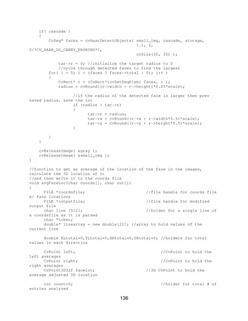
136
if( cascade )
{
CvSeq* faces = cvHaarDetectObjects( small_img, cascade, storage,
1.1, 2,
0/*CV_HAAR_DO_CANNY_PRUNING*/,
cvSize(30, 30) );
tar->r = 0; //initialize the target radius to 0
//cycle through detected faces to find the largest
for( i = 0; i < (faces ? faces->total : 0); i++ )
{
CvRect* r = (CvRect*)cvGetSeqElem( faces, i );
radius = cvRound((r->width + r->height)*0.25*scale);
//if the radius of the detected face is larger then prev
saved radius, save the loc
if (radius > tar->r)
{
tar->r = radius;
tar->x = cvRound((r->x + r->width*0.5)*scale);
tar->y = cvRound((r->y + r->height*0.5)*scale);
}
}
}
cvReleaseImage( &gray );
cvReleaseImage( &small_img );
}
//function to get an average of the location of the face in the images,
calculate the 3D location of it
//and then write it to the coords file
void avgFaceLoc(char coords[], char out[])
{
FILE *coordsfile; //file handle for coords file
w/ face locations
FILE *outputfile; //file handle for modified
output file
char line [512]; //holder for a single line of
a coordsfile as it is parsed
char *token;
double* linearray = new double[22]; //array to hold values of the
current line
double XLtotal=0,YLtotal=0,XRtotal=0,YRtotal=0; //holders for total
values in each direction
CvPoint left; //CvPoint to hold the
left averages
CvPoint right; //CvPoint to hold the
right averages
CvPoint3D32f faceloc; //3D CvPoint to hold the
average adjusted 3D location
int count=0; //holder for total # of
entries analyzed

137
int i;
//linearray guide
//[0]=TIME, [1]=PX1L, [2]=PY1L, [3]=PX1R, [4]=PY1R, [5]=X1, [6]=Y1,
[7]=Z1,
//[8]=PX2L, [9]=PY2L, [10]=PX2R, [11]=PY2R, [12]=X2, [13]=Y2, [14]=Z2,
[15]=FACE_PXL,
//[16]=FACE_PYL, [17]=FACE_PXR, [18]=FACE_PYR, [19]=FACE_X,
[20]=FACE_Y, [21]=FACE_Z
//currpoint guide
//[0]=FACE_PXL, [1]=FACE_PYL, [2]=FACE_PXR, [3]=FACE_PYR
coordsfile = fopen(coords, "r");
if (coordsfile == NULL)
{
printf("WARNING: Could NOT average and rewrite face
locations!!!\n");
return;
}
fgets(line, 512, coordsfile); //IGNORE 1st line b/c it is TITLES
for(;;) //loop forever
{
if(fgets(line, 512, coordsfile) != NULL) //get a line from
coordsfile
{
//tokenize the line
i=0;
token=strtok(line, DELIM);
linearray[0] = to_double(token);
while((token=strtok(NULL, DELIM))!=NULL)
{
i++;
linearray[i]=to_double(token);
}
//update totals
XLtotal+=linearray[15];
YLtotal+=linearray[16];
XRtotal+=linearray[17];
YRtotal+=linearray[18];
count++;
}
else
{
fclose(coordsfile);
break; //if we've reached the end of the file,
break out of the loop
}
}
//calculate averages
left.x = XLtotal/count;

138
left.y = YLtotal/count;
right.x = XRtotal/count;
right.y = YRtotal/count;
//calculate XYZ location;
calculateXYZ(&faceloc, left, right);
//rewrite the coords file
coordsfile = fopen(coords, "r");
outputfile = fopen(out, "w");
//write titles line to outputfile
fprintf(outputfile,"TIME,PX1L,PY1L,PX1R,PY1R,X1,Y1,Z1,PX2L,PY2L,PX2R,PY
2R,X2,Y2,Z2,FACE_PXL,FACE_PYL,FACE_PXR,FACE_PYR,FACE_X,FACE_Y,FACE_Z\n");
if (coordsfile == NULL || outputfile == NULL)
{
printf("WARNING: Could NOT average and rewrite face
locations!!!\n");
return;
}
fgets(line, 512, coordsfile); //IGNORE 1st line b/c it is TITLES
for(;;) //loop forever
{
if(fgets(line, 512, coordsfile) != NULL) //get a line from
coordsfile
{
//tokenize the line
i=0;
token=strtok(line, DELIM);
linearray[0] = to_double(token);
while((token=strtok(NULL, DELIM))!=NULL)
{
i++;
linearray[i]=to_double(token);
}
//print the line to our output file with the adjusted face
values
fprintf(outputfile,
"%f,%f,%f,%f,%f,%f,%f,%f,%f,%f,%f,%f,%f,%f,%f,%d,%d,%d,%d,%f,%f,%f\n",
linearray[0],linearray[1],linearray[2],linearray[3],linearray[4],linear
ray[5],linearray[6],
linearray[7],linearray[8],linearray[9],linearray[10],linearray[11],line
array[12],linearray[13],
linearray[14],left.x,left.y,right.x,right.y,faceloc.x,faceloc.y,faceloc
.z);
}
else
{
fclose(coordsfile);
fclose(outputfile);

139
break; //if we've reached the end of the file,
break out of the loop
}
}
printf ("****Averaging of Face Location and Rewrite Complete\n");
//cleanup
delete[] linearray;
}
//function to do simple inverse kinematics. in this case ISAC's arm is
represented as a 3 angle 2 link
//manipulator. we will only use angles 0, 1 and 2, and will lock the wrist
in place.
//this function takes in a 3D point as input and returns joint angles for
ISAC to reach to it.
//calculations of Theta 1 & 2 taken from page 69 of Modelling and Control of
Robotic Manipulators by
//L. Sciavicco & B. Siciliano
double* simpleInverseKinematics(CvPoint3D32f point, int rightleft)
{
//T = Theta = Angle
//X, Y, & Z are relative to ISAC's workspace thus: X= front to back,
Y=right to left, X=top to bottom
double T0, T1, T2, T4; //Theta 0, 1, 2, & 4 refer to
angles 0, 1, 2, & 4
double a, b, u, f, h; //holders for constant values
double Ta, Tb, v1, v2; //intermediate angle
calculations
double n,o; //intermediate values
for calculation of T0
double c2; //intermediate values
for calculation of T1 & T2
double x,y,z; //holder for absoulte
values of incoming point
double* ret = new double[6]; //return array for angles {T0, T1,
T2, 0, 0, 0}
double alpha, beta;
//set constant holders
a = CENTER_TO_ANGLE_0;
b = SHOULDER_OFFSET;
u = UPPERARM;
f = FOREARM;
h = HAND_L;
//adjust x, y, z for math
x = point.x;
if (rightleft == RIGHT_ARM)
{
y = -point.y;
}
else
{
y = point.y;
}
140
z = -point.z;
//Calculate Theta 0 (shoulder X Y)
if (y >= a)
{
Ta = atan(x/(y - a));
Tb = acos(b*sin(Ta)/x);
T0 = Tb - Ta;
}
else
{
n = a - y;
Tb = atan(x/n);
o = x/sin(Tb);
Ta = acos(b/o);
T0 = -(PI - Ta - Tb);
}
if (rightleft == RIGHT_ARM)
{
T0 = -T0;
}
//Calculate Theta 1 (elbow) & Theta 2 (shoulder X Z)
//**** current assumption that 0 on the Z axis is at shoulder level
//geometric solution
alpha = atan2(z,x);
beta = acos((x*x+z*z+u*u-(f+h)*(f+h))/(2*u*sqrt(x*x+z*z)));
c2 = (x*x + z*z - u*u - (f+h))/(2*u*(f+h));
//angles according to the book
v1 = alpha + beta;
v2 = acos(c2);
//conversion to ISAC's frame
T1 = v1;
T2 = -v2 - PI/2;
//Calculate Theta 4 (wrist up/down)
T4 = -(PI + T1 + T2);
//Convert to Degrees
T0=T0*R2D;
T1=T1*R2D;
T2=T2*R2D;
T4=T4*R2D;
//Ensure that final Theta values do not exceed ISAC's Range of Motion
if (rightleft == RIGHT_ARM)
{
if(T0 > ANG_R_0_MAX) T0 = ANG_R_0_MAX;
if(T0 < ANG_R_0_MIN) T0 = ANG_R_0_MIN;
if(T1 > ANG_R_1_MAX) T1 = ANG_R_1_MAX;
if(T1 < ANG_R_1_MIN) T1 = ANG_R_1_MIN;
if(T2 > ANG_R_2_MAX) T2 = ANG_R_2_MAX;

141
if(T2 < ANG_R_2_MIN) T2 = ANG_R_2_MIN;
if(T4 > ANG_R_4_MAX) T4 = ANG_R_4_MAX;
if(T4 < ANG_R_4_MIN) T4 = ANG_R_4_MIN;
}
else
{
if(T0 > ANG_L_0_MAX) T0 = ANG_L_0_MAX;
if(T0 < ANG_L_0_MIN) T0 = ANG_L_0_MIN;
if(T1 > ANG_L_1_MAX) T1 = ANG_L_1_MAX;
if(T1 < ANG_L_1_MIN) T1 = ANG_L_1_MIN;
if(T2 > ANG_L_2_MAX) T2 = ANG_L_2_MAX;
if(T2 < ANG_L_2_MIN) T2 = ANG_L_2_MIN;
if(T4 > ANG_L_4_MAX) T4 = ANG_L_4_MAX;
if(T4 < ANG_L_4_MIN) T4 = ANG_L_4_MIN;
}
//populate return array in degrees
ret[0]=T0;
ret[1]=T1;
ret[2]=T2;
ret[3]=0;
ret[4]=T4;
ret[5]=0;
return ret;
}
//function to convert the points from their current magic scale to a scale
suitable for ISAC's NN Controller
//also switch axes: X->Y, Y->Z, Z->X
//different approach then fitCoordstoISAC
void fitCoordsToISAC2(char coords[], char fittedcoords[], int rightleft)
{
FILE *coordsfile; //file handle for
coords to be uploaded
FILE *fittedcoordsfile; //file handle for
the newley fittted coords
int i,j;
char line [512]; //holder for a
single line of a coordsfile as it is parsed
double* linearray = new double[7]; //array to values hold
a line of coordsfile
double* currpoint = new double[4]; //array to hold values
of the current point (TIME,X1,Y1,Z1)
double* modpoint = new double[4]; //array to hold values
of the current point modified (TIME,X1,Y1,Z1)
double maxs[2][4]; //2D array to hold max values [0][i]=N/A,
X max TIME, Y max TIME, Z max TIME
//
[1][i]=N/A, X max, Y max, Z max
double mins[2][4]; //2D array to hold min values [0][i]=N/A,
X min TIME, Y min TIME, Z min TIME
//
[1][i]=N/A, X min, Y min, Z min
double diffs[4]; //array to hold maxs[1][i] - mins[1][i]
double div; //holder for the scale factor
double shift[4]; //array to hold shift factors

142
double armshift; //holder for the amount to shift the series1
(right arm) points by
int no_move=0; //flag to signify that no important
movement has been see
char *token;
//initialize maxs/mins
for(i=0;i<2;i++)
{
for(j=0;j<4;j++)
{
maxs[i][j]=-999999999999;
mins[i][j]=999999999999;
}
}
//GET MAX AND MIN FOR X, Y, Z (dont use Z but get it anyways)
//open coords files
coordsfile = fopen(coords, "r"); //coordinates to be parsed
fgets(line, 512, coordsfile); //ignore 1st line of TITLES
for(;;)
{
if(fgets(line, 512, coordsfile) != NULL) //get a line from
coordsfile
{
//tokenize the line
i=0;
token=strtok(line, DELIM);
linearray[0] = to_double(token);
while((token=strtok(NULL, DELIM))!=NULL)
{
i++;
linearray[i]=to_double(token);
}
//save to currpoint
for(i=0;i<4;i++)
{
currpoint[i]=linearray[i];
}
//find max/mins
for(i=1;i<4;i++)
{
if(currpoint[i] >= maxs[1][i])
{
maxs[0][i] = currpoint[0]; //set new max
time
maxs[1][i] = currpoint[i]; //set new max
value
}
if(currpoint[i] <= mins[1][i])
{
mins[0][i] = currpoint[0]; //set new min
time

143
mins[1][i] = currpoint[i]; //set new min
value
}
}
}
else
{
fclose(coordsfile);
break; //if we've reached the end of the file,
break out of the loop
}
}
//CALCULATE DIFFERENCES
for(i=1;i<4;i++)
{
diffs[i]=maxs[1][i]-mins[1][i]; //get the range of each
axes
}
//FIND BIGGEST RANGE & DIVIDE DIFFERENCE BY ISAC'S RANGE
if(diffs[1] > diffs[2])
{
if (diffs[1] > MIN_MOVEMENT)
div = diffs[1]/(ISAC_Y_MAX-ISAC_Y_MIN); //our X is ISAC's Y
else
no_move = 1;
}
else
{
if (diffs[2] > MIN_MOVEMENT)
div = diffs[2]/(ISAC_Z_MAX-ISAC_Z_MIN); //our Y is ISAC's Z
else
no_move = 1;
}
//CALCULATE SHIFT FACTOR based on Face Location
shift[1]=(mins[1][1]/div-FACE_Y)*-1;
shift[2]=(maxs[1][2]/div-FACE_Z)*-1;
//IF RIGHT ARM :: GET LARGEST LEFT/RIGHT (X->Y) VALUE
armshift = maxs[1][1]/div+shift[1];
//REWRITE FILE LINE BY LINE APPLYING SCALE/SHIFT AND REARRANGING AXES
AND SET ISAC_X = 400
coordsfile = fopen(coords, "r"); //coordinates to
be parsed
fittedcoordsfile = fopen(fittedcoords, "w"); //fitted coordinates
file
fgets(line, 512, coordsfile); //ignore 1st line
of TITLES
for(;;)
{
if(fgets(line, 512, coordsfile) != NULL) //get a line from
coordsfile

144
{
//tokenize the line
i=0;
token=strtok(line, DELIM);
linearray[0] = to_double(token);
while((token=strtok(NULL, DELIM))!=NULL)
{
i++;
linearray[i]=to_double(token);
}
//save to currpoint
for(i=0;i<4;i++)
{
currpoint[i]=linearray[i];
}
modpoint[0]=currpoint[0];
for(i=1;i<4;i++)
{
modpoint[i]=currpoint[i]/div+shift[i]; //scale &
shift the point
}
if (rightleft == RIGHT_ARM)
{
modpoint[1]=modpoint[1]-armshift;
}
//SAFTEY SHIFT
//shift the points further from the center to ensure ISAC
wont hit his own hands together
if (rightleft == RIGHT_ARM)
{
modpoint[1]=modpoint[1]-SAFTEY_SHIFT;
}
else
{
modpoint[1]=modpoint[1]+SAFTEY_SHIFT;
}
//write to the new file in ISAC's order
if (no_move)
fprintf(fittedcoordsfile,
"%f,%f,%f,%f\n",modpoint[0],FOREARM+HAND_L,CENTER_TO_ANGLE_0+SHOULDER_OFFSET,
-UPPERARM);
else
fprintf(fittedcoordsfile,
"%f,%f,%f,%f\n",modpoint[0],CONST_X,modpoint[1],modpoint[2]);
}
else
{
fclose(coordsfile);
fclose(fittedcoordsfile);
145
break; //if we've reached the end of the file,
break out of the loop
}
}
printf ("****Fitting to ISAC Complete\n");
//cleanup
delete[] linearray;
delete[] currpoint;
delete[] modpoint;
}
void flipY(char coords[], char flippedYcoords[])
{
FILE * coordsfile; //file handle to store
unparsed coordinates
FILE * flippedfile; //file handle to store
flipped Y coords
char line [512]; //holder for a single line of
coordsfile as it is parsed
char *token;
double* linearray = new double[22]; //array of
doubles to hold unfiltered values
double Y1tot=0,Y2tot=0,Yftot=0;
double Y1avg,Y2avg,Yfavg;
double count=0;
int i;
//**********************************
//****** Get Y1 & Y2 AVERAGES ******
//**********************************
//GET FIRST ENTRY (line 2) FOR FILTERING HISTORY
//linearray guide
//[0]=TIME, [1]=PX1L, [2]=PY1L, [3]=PX1R, [4]=PY1R, [5]=X1, [6]=Y1,
[7]=Z1,
//[8]=PX2L, [9]=PY2L, [10]=PX2R, [11]=PY2R, [12]=X2, [13]=Y2, [14]=Z2,
[15]=FACE_PXL,
//[16]=FACE_PYL, [17]=FACE_PXR, [18]=FACE_PYR, [19]=FACE_X,
[20]=FACE_Y, [21]=FACE_Z
coordsfile = fopen(coords, "r"); //open coordsfile (to be filtered)
fgets(line, 512, coordsfile); //get 1st line to
ignore it b/c it is TITLES
if(fgets(line, 512, coordsfile) != NULL) //get a line from
coordsfile
{
//tokenize the line
i=0;
token=strtok(line, DELIM);
linearray[0] = to_double(token);
while((token=strtok(NULL, DELIM))!=NULL)
{
i++;
linearray[i]=to_double(token);
}

146
Y1tot=Y1tot+linearray[6];
Y2tot=Y2tot+linearray[13];
Yftot=Yftot+linearray[20];
count++;
}
fclose(coordsfile);
//calculate average Y value
Y1avg=Y1tot/count;
Y2avg=Y2tot/count;
Yfavg=Yftot/count;
//***************************************
//****** REWRITE Y1 & Y2 (FLIPPED) ******
//***************************************
//start back at the beginning
coordsfile = fopen(coords, "r"); //open coordsfile
(to be flipped)
flippedfile = fopen(flippedYcoords, "w"); //open flippedycoords
(to hold flipped Y coords)
fprintf(flippedfile,"TIME,PX1L,PY1L,PX1R,PY1R,X1,Y1,Z1,PX2L,PY2L,PX2R,P
Y2R,X2,Y2,Z2,FACE_PXL,FACE_PYL,FACE_PXR,FACE_PYR,FACE_X,FACE_Y,FACE_Z\n");
fgets(line, 512, coordsfile);
//ignore 1st line of coordsfile b/c it is TITLES
while(1) //loop forever
{
if(fgets(line, 512, coordsfile) != NULL) //get a line for
coordsfile
{
//GET NEXT LINE
//tokenize the line
i=0;
token=strtok(line, DELIM);
linearray[0] = to_double(token);
while((token=strtok(NULL, DELIM))!=NULL)
{
i++;
linearray[i]=to_double(token);
}
//print to new file
fprintf(flippedfile,"%f,%f,%f,%f,%f,%f,%f,%f,%f,%f,%f,%f,%f,%f,%f,%f,%f
,%f,%f,%f,%f,%f\n",
linearray[0],linearray[1],linearray[2],linearray[3],linearray[4],linear
ray[5],
2*Y1avg-
linearray[6],linearray[7],linearray[8],linearray[9],linearray[10],linearray[1
1],
linearray[12],2*Y2avg-
linearray[13],linearray[14],linearray[15],linearray[16],linearray[17],
linearray[18],linearray[19],2*Yfavg-
linearray[20],linearray[21]);
}

147
else //if we reach the end of the file break out of the
while loop
{
//close files
fclose(coordsfile);
fclose(flippedfile);
break;
}
}
printf ("****Y Flipping Complete\n");
//cleanup
delete[] linearray;
}
void interpolateAngles(char anglesIn[], char anglesOut[])
{
FILE *anglesInFile;
FILE *anglesOutFile;
char line [512]; //holder for a single line of
anglesIn as it is parsed
char *token;
double* currangles = new double[7]; //array of doubles to hold current
angles
double* lastangles = new double[7]; //array to hold the last angles
double span;
double* increments = new double[7]; //array to hold the increments for
the interpolation ([0] unused)
int i;
//linearray guide
//[0]=TIME, [1]=Ang0, [2]=Ang1, [3]=Ang2, [4]=Ang3, [5]=Ang4, [6]=Ang5
anglesInFile = fopen(anglesIn, "r"); //open file with angles
to be interpolated
anglesOutFile = fopen(anglesOut, "w"); //open file to write
interpolated angles to
//get 1st line from anglesIn
if(fgets(line, 512, anglesInFile) != NULL)
{
//tokenize the line
i=0;
token=strtok(line, DELIM);
lastangles[0] = to_double(token);
while((token=strtok(NULL, DELIM))!=NULL)
{
i++;
lastangles[i]=to_double(token);
}
}
while(1)
{

148
//get a line from anglesIn
if(fgets(line, 512, anglesInFile) != NULL)
{
//tokenize the line
i=0;
token=strtok(line, DELIM);
currangles[0] = to_double(token);
while((token=strtok(NULL, DELIM))!=NULL)
{
i++;
currangles[i]=to_double(token);
}
span = currangles[0] - lastangles[0]; //get the time
between 2 sets of angles
//calculate increments for interpolation
for(i=1;i<7;i++)
{
increments[i]=(currangles[i] - lastangles[i])/span;
}
//write original point + new interpolated points
for(i=0;i<span;i++)
{
fprintf(anglesOutFile,"%f,%f,%f,%f,%f,%f,%f\n",
lastangles[0]+i,
lastangles[1]+i*increments[1],
lastangles[2]+i*increments[2],
lastangles[3]+i*increments[3],
lastangles[4]+i*increments[4],
lastangles[5]+i*increments[5],
lastangles[6]+i*increments[6]);
}
}
else //break out of the loop if we have reached the end of the
file
{
break;
}
//update lastpoint
for(i=0;i<7;i++)
{
lastangles[i]=currangles[i];
}
}
//print out the last point
fprintf(anglesOutFile,"%f,%f,%f,%f,%f,%f,%f\n",lastangles[0],lastangles
[1],lastangles[2],lastangles[3],
lastangles[4],lastangles[5],lastangles[6]);
//close files
fclose(anglesInFile);
fclose(anglesOutFile);
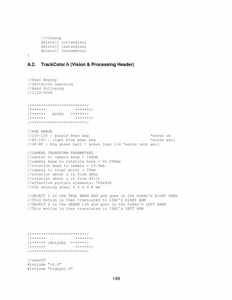
149
//cleanup
delete[] currangles;
delete[] lastangles;
delete[] increments;
}
A.2. TrackColor.h (Vision & Processing Header)
//Sean Begley
//Imitation Learning
//Hand Following
//1/23/2008
/*************************/
/******* *******/
/******* NOTES *******/
/******* *******/
/*************************/
//HUE RANGE
//135-155 : purple bean bag *works ok
//80-100 : light blue bean bag *works well
//40-80 : big green ball / green lego lid *works very well
//CAMERA TRANSFORM PARAMETERS
//center to camera base = 140mm
//camera base to rotation base = 91.948mm
//rotation base to camera = 65.5mm
//camera to focal point = 39mm
//rotation about z is from dPan
//rotation about y if from dTilt
//effective picture elements: 768x494
//CCD sensing area: 6.4 x 4.8 mm
//OBJECT 1 is the TEAL BEAN BAG and goes in the human's RIGHT HAND
//This motion is then translated to ISAC's RIGHT ARM
//OBJECT 2 is the GREEN LID and goes in the human's LEFT HAND
//This motion is then translated to ISAC's LEFT ARM
/*************************/
/******* *******/
/******* INCLUDES *******/
/******* *******/
/*************************/
//openCV
#include "cv.h"
#include "highgui.h"
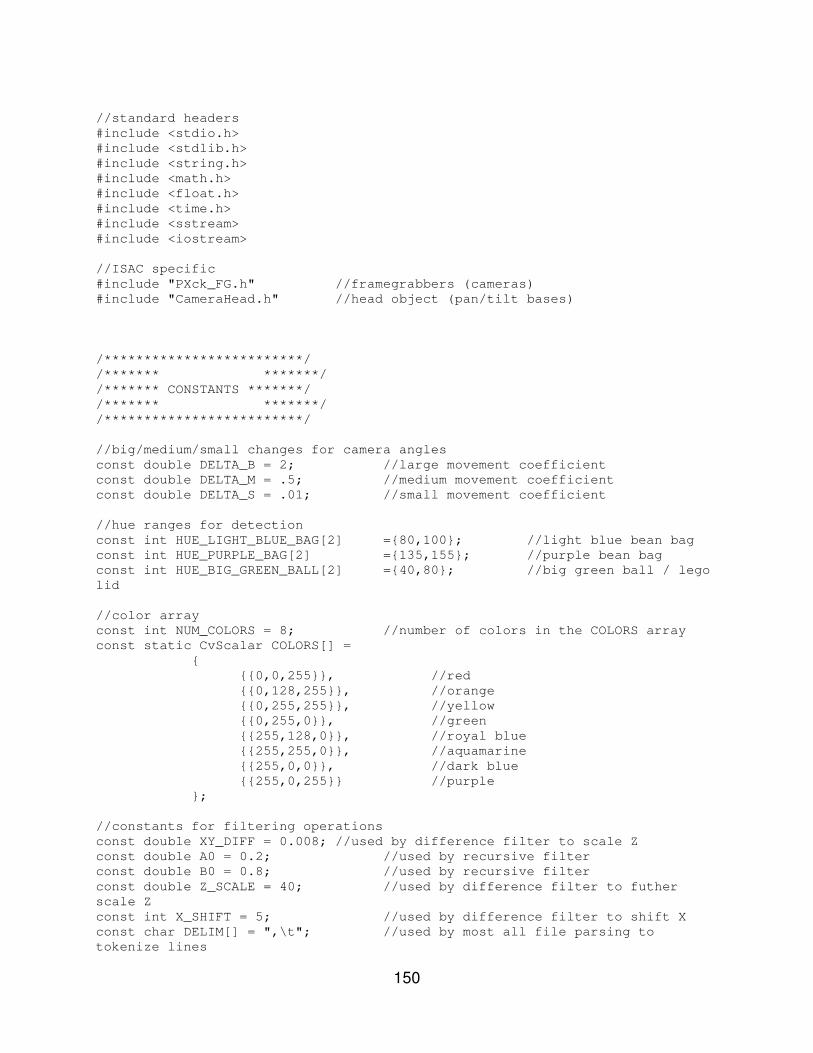
150
//standard headers
#include <stdio.h>
#include <stdlib.h>
#include <string.h>
#include <math.h>
#include <float.h>
#include <time.h>
#include <sstream>
#include <iostream>
//ISAC specific
#include "PXck_FG.h" //framegrabbers (cameras)
#include "CameraHead.h" //head object (pan/tilt bases)
/*************************/
/******* *******/
/******* CONSTANTS *******/
/******* *******/
/*************************/
//big/medium/small changes for camera angles
const double DELTA_B = 2; //large movement coefficient
const double DELTA_M = .5; //medium movement coefficient
const double DELTA_S = .01; //small movement coefficient
//hue ranges for detection
const int HUE_LIGHT_BLUE_BAG[2] ={80,100}; //light blue bean bag
const int HUE_PURPLE_BAG[2] ={135,155}; //purple bean bag
const int HUE_BIG_GREEN_BALL[2] ={40,80}; //big green ball / lego
lid
//color array
const int NUM_COLORS = 8; //number of colors in the COLORS array
const static CvScalar COLORS[] =
{
{{0,0,255}}, //red
{{0,128,255}}, //orange
{{0,255,255}}, //yellow
{{0,255,0}}, //green
{{255,128,0}}, //royal blue
{{255,255,0}}, //aquamarine
{{255,0,0}}, //dark blue
{{255,0,255}} //purple
};
//constants for filtering operations
const double XY_DIFF = 0.008; //used by difference filter to scale Z
const double A0 = 0.2; //used by recursive filter
const double B0 = 0.8; //used by recursive filter
const double Z_SCALE = 40; //used by difference filter to futher
scale Z
const int X_SHIFT = 5; //used by difference filter to shift X
const char DELIM[] = ",\t"; //used by most all file parsing to
tokenize lines
151
//constants related to ISAC's
const double ISAC_X_MIN = 400; //ISAC's left arm workspace
const double ISAC_X_MAX = 400;
const double ISAC_Y_MIN = 100;
const double ISAC_Y_MAX = 500;
const double ISAC_Z_MIN = -400;
const double ISAC_Z_MAX = 300;
const double FACE_X = 0; //FACE_X is not used
const double FACE_Y = 0;
const double FACE_Z = 300;
const double ANG_L_0_MIN = -30;//-58.372; //the min/max angles for the left
arm joints
const double ANG_L_0_MAX = 14.995;
const double ANG_L_1_MIN = 35.760;
const double ANG_L_1_MAX = 120.25;
const double ANG_L_2_MIN = -210.378;
const double ANG_L_2_MAX = -144.212;
const double ANG_L_4_MIN = -40;
const double ANG_L_4_MAX = 40;
const double ANG_R_0_MIN = -14.995; //the min/max angles for the right
arm joints
const double ANG_R_0_MAX = 30;//58.372;
const double ANG_R_1_MIN = 35.760;
const double ANG_R_1_MAX = 120.25;
const double ANG_R_2_MIN = -210.378;
const double ANG_R_2_MAX = -144.212;
const double ANG_R_4_MIN = -40;
const double ANG_R_4_MAX = 40;
const double CONST_X = 300; //constant depth for ignoring depth
const double CENTER_TO_ANGLE_0 = 246; //various lengths on ISAC
const double SHOULDER_OFFSET = 200;
const double UPPERARM = 325;
const double FOREARM = 290;
const double HAND_L = 250;
//constants for Program Usages
const int LEFT_ARM = 1;
const int RIGHT_ARM = 0;
const int END_EFF_YES = 1;
const int END_EFF_NO = 0;
const int SIMPLE_INV_KIN = 1;
const int COMPLEX_INV_KIN = 0;
const int VISION_TIME = 400; //max time it takes to complete a
detection cycle
const int MIN_MOVEMENT = 5000; //minium amount of movement in the
X & Y directions that will be counted
const int SAFTEY_SHIFT = 100; //amount to move ISAC's hands away from
the center (0) to ensure they dont hit
//general constants

152
const double PI = 3.14159265359;
const double R2D = (180.0 / PI);
const double D2R = (PI / 180.0);
/*************************/
/******* *******/
/******* GLOBAL *******/
/******* VARIABLES *******/
/******* *******/
/*************************/
//variables for getConnectedComps
int compmax=0;
int compcap=40; //should be the same size as the length of Comps
below
int maxcomp=0;
int comptot=0;
double maxarea=0;
static CvConnectedComp ** Comps = new CvConnectedComp*[40]; //holder
for Connected Components
//variables for pan/tilt units
CameraHead hd; //head object (pan/tilts)
//Haar face detection
static CvMemStorage* storage = 0;
static CvHaarClassifierCascade* cascade = 0;
void detect_and_draw( IplImage* image );
const char* cascade_name =
"haarcascade_frontalface_alt.xml";
/* "haarcascade_profileface.xml";*/
/*************************/
/******* *******/
/******* CLASSES *******/
/******* *******/
/*************************/
//CvTarget: an extension of the CvPoint class... basically just a point (int
x, int y) with a radius (int r)
class CvTarget : public CvPoint
{
public:
CvTarget();
CvTarget(int xi, int yi, int ri);
int r;
153
};
CvTarget::CvTarget () { //default constructor
x=0;
y=0;
r=0;
}
CvTarget::CvTarget (int xi, int yi, int ri) { //constructor with user input
x = xi;
y = yi;
r = ri;
}
/**************************/
/******* *******/
/******* FUNCTION *******/
/******* PROTOTYPES *******/
/******* *******/
/**************************/
void detectObject(IplImage* img, CvTarget *tar, int low, int high);
void drawTarget(IplImage* img, CvTarget obj, int clr);
void getConnectedComps(IplImage *image, CvConnectedComp ** Comps);
void centerCams(int *lX, int *lY, int *rX, int *rY);
void calculateXYZ(CvPoint3D32f *objloc, CvPoint left, CvPoint right);
double to_double ( const char *p );
void filterCoords(char coords[], char tempcoords[], char filteredcoords[]);
void compressCoords(char coords[], char compressedcoords1[], char
compressedcoords2[]);
double abs(double Nbr);
void uploadToNN1by1(char uploadL[], char uploadR[], char coordsL[], char
coordsR[]);
void uploadToNNbatch(char uploadL[], char uploadR[], char coordsL[], char
coordsR[]);
void fitCoordsToISAC(char coords[], char fittedcoords[]);
void testSetForInverseKinematics(char test[], int Xmin, int Xmax, int Ymin,
int Ymax, int Zmin, int Zmax, int stepSize);
void testSetForForwardKinematics(char test[], double maxAngle, double
stepSize);
void calcJointAngles(char coords[], char angles[], int rightleft, int EndEff,
int simple);
void inverseKinematics(double * pdPos, double * pdAngles, short m_sLeftArm,
short m_sEndEffector);
void uploadGoFlag(char loc[]);
void haarFaceDetect(IplImage* img, CvTarget *tar);
void avgFaceLoc(char coords[], char out[]);
double* simpleInverseKinematics(CvPoint3D32f point, int rightleft);
void fitCoordsToISAC2(char coords[], char fittedcoords[], int rightleft);
void flipY(char coords[], char flippedYcoords[]);
void interpolateAngles(char anglesIn[], char anglesOut[]);
154
B. Control Code Listing
B.3. main.cpp (main Control loop code)
#include "Headers\stdafx.h"
#include <windows.h>
#include <windef.h>
#include <string.h>
#include <stdlib.h>
#include <stdio.h>
#include <conio.h>
#include <stdarg.h>
#include <math.h>
#include <IOSTREAM>
#include <sstream>
#include "Headers\winmotenc.h"
#include "Headers\Control.h"
#include "Headers\NNMuscleClass.h"
#include "Headers\MahirKinematics.h"
#include "Headers\PID.h"
#include "Headers\commport.h"
#include "Headers\GripControl.h"
#ifdef _ATL_STATIC_REGISTRY
#include <statreg.h>
#include <statreg.cpp>
#endif
#include <atlimpl.cpp>
using namespace std;
double leftValvesOutputs[12]={0};
double leftValvesInputs[12]={0};
double InitialleftValvesOutputs[12];
long leftEncoders[6]={0};
double leftAngles[6]={0};
double rightValvesOutputs[12]={0};
double rightValvesInputs[12]={0};
double InitialrightValvesOutputs[12];
long rightEncoders[6]={0};
double rightAngles[6]={0};
double
LPID0_output=0.0,LPID1_output=0.0,LPID2_output=0.0,LPID3_output=0.0,LPID4_out
put=0.0,LPID5_output=0.0;
//Kinematic variables
#define PI 3.14159265
/*double lengthOfEndEff;
double *alpha,*a,*d,*theta;
155
double **rotation;
double **limitsOfThetas;
double **T01;
double **T12;
double **T23;
double **T34;
double **T45;
double **T56;
double **T02;
double **T03;
double **T04;
double **T05;
double **T06;
double *j1Pos;
double *j2Pos;
double *j3Pos;
double *j4Pos;
double *j5Pos;
double *j6Pos;
double *endEffPos;
*/
double* optimumRotations( double *desPos, double *prevThetas, double alpha,
double beta, double gamma);
double to_double( const char *p);
const char DELIM[]=",\t";
void main()
{
int count=0,numb=0;
float desiredangleL0 =0.0, desiredangleL1 =0.0, desiredangleL2 =0.0,
desiredangleL3 =0.0, desiredangleL4 =0.0, desiredangleL5 =0.0;
float desiredangleR0 =0.0, desiredangleR1 =0.0, desiredangleR2 =0.0,
desiredangleR3 =0.0, desiredangleR4 =0.0, desiredangleR5 =0.0;
float incrementalVoltage0 = 0.0, incrementalVoltage1 =
0.0,incrementalVoltage2 = 0.0,incrementalVoltage3 = 0.0,incrementalVoltage4 =
0.0, incrementalVoltage5 = 0.0;
double gamma = 0, beta = 0.0, alpha = 0.0;
double *desPos = (double*)malloc(3*sizeof(double));
double *prevThetasL = (double*)malloc(6*sizeof(double));
double *prevThetasR = (double*)malloc(6*sizeof(double));
double *thetas = (double*)malloc(6*sizeof(double));
int solutionexist = 0;
double timevalL;
double timevalR;
char lineL[512];
char lineR[512];
int i;
char *token;
double *currangsL = new double[6];
double *currangsR = new double[6];
int totalstep = 50;
FILE *anglesfileL;
FILE *anglesfileR;

156
int waitL = 0;
int waitR = 0;
double *anglesL = new double[6];
double *anglesR = new double[6];
int Ldone=0;
int Rdone=0;
FILE *StartNowFile;
//TEST VARIABLES: Set these to 1 for use, 0 for no use
int usecontrol=1, useleft=1, useright=1, useStartNow=0;
//GripControl gripper;
// Left Arm Objects
CNNMuscles
LeftNNMusclesAngle0F(1,0,1);LeftNNMusclesAngle0F.Allocator();CNNMuscles
LeftNNMusclesAngle0B(1,0,-1);LeftNNMusclesAngle0B.Allocator();
CNNMuscles
LeftNNMusclesAngle1F(1,1,1);LeftNNMusclesAngle1F.Allocator();CNNMuscles
LeftNNMusclesAngle1B(1,1,-1);LeftNNMusclesAngle1B.Allocator();
CNNMuscles
LeftNNMusclesAngle2F(1,2,1);LeftNNMusclesAngle2F.Allocator();CNNMuscles
LeftNNMusclesAngle2B(1,2,-1);LeftNNMusclesAngle2B.Allocator();
//CNNMuscles
LeftNNMusclesAngle3F(1,3,1);LeftNNMusclesAngle3F.Allocator();CNNMuscles
LeftNNMusclesAngle3B(1,3,-1);LeftNNMusclesAngle3B.Allocator();
CNNMuscles
LeftNNMusclesAngle4F(1,4,1);LeftNNMusclesAngle4F.Allocator();CNNMuscles
LeftNNMusclesAngle4B(1,4,-1);LeftNNMusclesAngle4B.Allocator();
//CNNMuscles
LeftNNMusclesAngle5F(1,5,1);LeftNNMusclesAngle5F.Allocator();CNNMuscles
LeftNNMusclesAngle5B(1,5,-1);LeftNNMusclesAngle5B.Allocator();
// Right Arm Objects
CNNMuscles
RightNNMusclesAngle0F(0,0,1);RightNNMusclesAngle0F.Allocator();CNNMuscles
RightNNMusclesAngle0B(0,0,-1);RightNNMusclesAngle0B.Allocator();
CNNMuscles
RightNNMusclesAngle1F(0,1,1);RightNNMusclesAngle1F.Allocator();CNNMuscles
RightNNMusclesAngle1B(0,1,-1);RightNNMusclesAngle1B.Allocator();
CNNMuscles
RightNNMusclesAngle2F(0,2,1);RightNNMusclesAngle2F.Allocator();CNNMuscles
RightNNMusclesAngle2B(0,2,-1);RightNNMusclesAngle2B.Allocator();
//CNNMuscles
LeftNNMusclesAngle3F(1,3,1);LeftNNMusclesAngle3F.Allocator();CNNMuscles
LeftNNMusclesAngle3B(1,3,-1);LeftNNMusclesAngle3B.Allocator();
//CNNMuscles
LeftNNMusclesAngle4F(1,4,1);LeftNNMusclesAngle4F.Allocator();CNNMuscles
LeftNNMusclesAngle4B(1,4,-1);LeftNNMusclesAngle4B.Allocator();
//CNNMuscles
LeftNNMusclesAngle5F(1,5,1);LeftNNMusclesAngle5F.Allocator();CNNMuscles
LeftNNMusclesAngle5B(1,5,-1);LeftNNMusclesAngle5B.Allocator();
if (usecontrol) InitializeCards();
if (usecontrol && useleft)
{InitializeLeftValves();/*gripper.SimpleOpen()*/;Sleep(1500);}
if (usecontrol && useright)
{InitializeRightValves();/*gripper.SimpleOpen()*/;Sleep(1500);}

157
Sleep(3000);
// Precise Sampling Time Initialization
LARGE_INTEGER ticksPerSecond,start_ticks, end_ticks, cputime,tick;
if (!QueryPerformanceFrequency(&ticksPerSecond))
if (!QueryPerformanceCounter(&tick) )
printf("no go counter not installed");
// Data File Initialization
FILE *outputdata;
if((outputdata = fopen(".\\MatlabWork\\MatlabWork.txt","w")) == NULL)
printf("Can't Open File MatlabWork.txt\n");
// Homing & Reset Encoders Left
if (usecontrol){Sleep(100);/*gripper.SimpleOpen()*/;Sleep(500);}
if (usecontrol && useleft) { ResetLeftEncoders();vitalSelectBoard(0);}
if (usecontrol && useright) {
ResetRightEncoders();vitalSelectBoard(1);}
//set angles in radians
alpha = 0*PI/180; //Hold z of base frame (deg*PI/180)
beta = -90*PI/180; //Hold y of rotated base frame (deg*PI/180)
gamma = 0*PI/180; //Hold x of rotated base frame (deg*PI/180)
thetas[0] = 10.0;
while(1)
{
//check to see if the Start.Now files exists to see if it is time
go
while(1)
{
if (useStartNow==0) break; //if we are ignoring the
start file, break out
else StartNowFile = fopen("I:/Temp/Start.Now","r");
if (StartNowFile != NULL) break; //if we find a start
file break out
if (kbhit()) break; //if someone hits a key,
break out
Sleep(10);
}
if (kbhit()) break; //if someone hits a key, break out
//setup variables for another run
waitL=0;
waitR=0;
Ldone=0;
Rdone=0;
count=0;
//set prevThetas to home position
prevThetasL[0] = 0.0;
prevThetasL[1] = 90;//PI/2.0;
prevThetasL[2] = -180;//-PI;
prevThetasL[3] = 0.0;
prevThetasL[4] = 0;//PI/50.0; //For left arm
prevThetasL[5] = 0.0;

158
prevThetasR[0] = 0.0;
prevThetasR[1] = 90;//PI/2.0;
prevThetasR[2] = -180;//-PI;
prevThetasR[3] = 0.0;
prevThetasR[4] = 0;
prevThetasR[5] = 0.0;
//open files with joint angles to goto
anglesfileL = fopen("I:/Temp/uploadL.txt", "r");
anglesfileR = fopen("I:/Temp/uploadR.txt", "r");
//loop through all points in the uploadL & uploadR files
printf("Control Loop Starts!!\n");
for(;;)
{
QueryPerformanceCounter(&start_ticks);
//LEFT
//get angles from file
if (waitL == 0)
{
if(fgets(lineL, 512, anglesfileL) != NULL)
{
i=0;
token=strtok(lineL, DELIM);
timevalL = to_double(token);
while((token=strtok(NULL, DELIM))!=NULL)
{
currangsL[i]=to_double(token);
i++;
}
}
else
{
Ldone=1; //if we reach the end of the file
set the Left done flag
}
}
//if the timeval (in our file) is <= the current count then
goto the point
//otherwise wait until timevalL is equal to count
if(timevalL <= count)
{
waitL = 0;
for(i=0;i<6;i++)
anglesL[i]=currangsL[i];
}
else
{
waitL=1;
}
//RIGHT
//get angles from file
if (waitR == 0)
{

159
if(fgets(lineR, 512, anglesfileR) != NULL)
{
i=0;
token=strtok(lineR, DELIM);
timevalR = to_double(token);
while((token=strtok(NULL, DELIM))!=NULL)
{
currangsR[i]=to_double(token);
i++;
}
}
else
{
Rdone=1; //if we reach the end of the file
set the Right done flag
}
}
//if the timeval (in our file) is <= the current count then
goto the point
//otherwise wait until timevalL is equal to count
if(timevalR <= count)
{
waitR = 0;
for(i=0;i<6;i++)
anglesR[i]=currangsR[i];
}
else
{
waitR=1;
}
//printf("**THETAS: %f, %f, %f, %f, %f, %f\n",
thetas[0],thetas[1],thetas[2],thetas[3],thetas[4],thetas[5]);
if(anglesL && anglesR == NULL)
//if (!solutionexist)
{
printf("No Solution Exists!\n");
// Closing the Controls
if (usecontrol)
{/*gripper.GrabSomething()*/;CloseValves();Sleep(500);vitalQuit();Sleep
(500);}
fclose(outputdata);
return;
}
//Control loop
//printf("%d :: ",(int)timevalL);
//if we're done then get us back to the home position
if (Ldone == 1 && Rdone == 1)
{
Sleep(4000);
desiredangleL0 = 0;
desiredangleL1 = 90;

160
desiredangleL2 = -180;
desiredangleL3 = 0;
desiredangleL4 = 0;
desiredangleL5 = 0;
desiredangleR0 = 0;
desiredangleR1 = 90;
desiredangleR2 = -180;
desiredangleR3 = 0;
desiredangleR4 = 0;
desiredangleR5 = 0;
}
//otherwise set the desired angles to the retrieved angles
else
{
desiredangleL0 = anglesL[0];
desiredangleL1 = anglesL[1];
desiredangleL2 = anglesL[2];
desiredangleL3 = anglesL[3];
desiredangleL4 = anglesL[4];
desiredangleL5 = anglesL[5];
desiredangleR0 = anglesR[0];
desiredangleR1 = anglesR[1];
desiredangleR2 = anglesR[2];
desiredangleR3 = anglesR[3];
desiredangleR4 = 0;//anglesR[4];
desiredangleR5 = anglesR[5];
}
if(kbhit()) break;
// Left Arm
//ANGLE 0
if( prevThetasL[0] > desiredangleL0 )
LeftNNMusclesAngle0B.Process(&desiredangleL0,&incrementalVoltage0);
else if( prevThetasL[0] < desiredangleL0 )
LeftNNMusclesAngle0F.Process(&desiredangleL0,&incrementalVoltage0);
leftValvesOutputs[0] = InitialleftValvesOutputs[0] -
incrementalVoltage0;
leftValvesOutputs[1] = InitialleftValvesOutputs[1] +
incrementalVoltage0;
//ANGLE 1
if( prevThetasL[1] < desiredangleL1 )
LeftNNMusclesAngle1F.Process(&desiredangleL1,&incrementalVoltage1);
else if( prevThetasL[1] > desiredangleL1 )
LeftNNMusclesAngle1B.Process(&desiredangleL1,&incrementalVoltage1);
leftValvesOutputs[2] =
InitialleftValvesOutputs[2]+incrementalVoltage1;
leftValvesOutputs[3] = InitialleftValvesOutputs[3]-
incrementalVoltage1;

161
//ANGLE 2
if( prevThetasL[2] > desiredangleL2 )
LeftNNMusclesAngle2B.Process(&desiredangleL2,&incrementalVoltage2);
else if( prevThetasL[2] < desiredangleL2 )
LeftNNMusclesAngle2F.Process(&desiredangleL2,&incrementalVoltage2);
leftValvesOutputs[4] = InitialleftValvesOutputs[4] +
incrementalVoltage2 - incrementalVoltage3;
leftValvesOutputs[5] = InitialleftValvesOutputs[5] -
incrementalVoltage2 - incrementalVoltage3;
leftValvesOutputs[6] = InitialleftValvesOutputs[6] -
incrementalVoltage2 + incrementalVoltage3;
leftValvesOutputs[7] = InitialleftValvesOutputs[7] +
incrementalVoltage2 + incrementalVoltage3;
//ANGLE 4
if( prevThetasL[4] > desiredangleL4 )
LeftNNMusclesAngle4B.Process(&desiredangleL4,&incrementalVoltage4);
else if( prevThetasL[4] < desiredangleL4 )
LeftNNMusclesAngle4F.Process(&desiredangleL4,&incrementalVoltage4);
leftValvesOutputs[8] = InitialleftValvesOutputs[8] -
incrementalVoltage4 - incrementalVoltage5 ;
leftValvesOutputs[9] = InitialleftValvesOutputs[9] +
incrementalVoltage4 + incrementalVoltage5;
leftValvesOutputs[10]= InitialleftValvesOutputs[10] -
incrementalVoltage4 + incrementalVoltage5;
leftValvesOutputs[11]= InitialleftValvesOutputs[11] +
incrementalVoltage4 - incrementalVoltage5;
// Right Arm
//ANGLE 0
if( prevThetasR[0] > desiredangleR0 )
{
RightNNMusclesAngle0B.Process(&desiredangleR0,&incrementalVoltage0);
}
else if( prevThetasR[0] < desiredangleR0 )
{
RightNNMusclesAngle0F.Process(&desiredangleR0,&incrementalVoltage0);
}
rightValvesOutputs[0] = InitialrightValvesOutputs[0] -
incrementalVoltage0;
rightValvesOutputs[1] = InitialrightValvesOutputs[1] +
incrementalVoltage0;
//ANGLE 1
if( prevThetasR[1] < desiredangleR1 )
{
RightNNMusclesAngle1F.Process(&desiredangleR1,&incrementalVoltage1);
}
else if( prevThetasR[1] > desiredangleR1 )
{

162
RightNNMusclesAngle1B.Process(&desiredangleR1,&incrementalVoltage1);
}
rightValvesOutputs[2] =
InitialrightValvesOutputs[2]+incrementalVoltage1;
rightValvesOutputs[3] = InitialrightValvesOutputs[3]-
incrementalVoltage1;
//ANGLE 2
if( prevThetasR[2] > desiredangleR2 )
{
RightNNMusclesAngle2B.Process(&desiredangleR2,&incrementalVoltage2);
}
else if( prevThetasR[2] < desiredangleR2 )
{
RightNNMusclesAngle2F.Process(&desiredangleR2,&incrementalVoltage2);
}
rightValvesOutputs[4] = InitialrightValvesOutputs[4] +
incrementalVoltage2 - incrementalVoltage3;
rightValvesOutputs[5] = InitialrightValvesOutputs[5] -
incrementalVoltage2 - incrementalVoltage3;
rightValvesOutputs[6] = InitialrightValvesOutputs[6] -
incrementalVoltage2 + incrementalVoltage3;
rightValvesOutputs[7] = InitialrightValvesOutputs[7] +
incrementalVoltage2 + incrementalVoltage3;
if (usecontrol && useleft && !waitL) SetLeftArmPressures();
if (usecontrol && useright && !waitR)
SetRightArmPressures();
QueryPerformanceCounter(&end_ticks); //printf("time
pass:%f\n",(float)(end_ticks.QuadPart-
start_ticks.QuadPart)/ticksPerSecond.QuadPart*1000);
while(((float)(end_ticks.QuadPart-
start_ticks.QuadPart)/ticksPerSecond.QuadPart*1000) < (float) 50)
QueryPerformanceCounter(&end_ticks); cputime.QuadPart =
end_ticks.QuadPart- start_ticks.QuadPart;
// Reading the Angles
printf("LEFT: %d ",(int)timevalL);
if (usecontrol &&
useleft){ReadLeftEncoders();RealLeftAngles();}
printf("RIGHT: %d ",(int)timevalR);
if (usecontrol &&
useright){ReadRightEncoders();RealRightAngles();}
// Update the voltage output references
fprintf(outputdata,"%d %.2f %.2f %.2f\n",count,
desiredangleL0, leftAngles[0], incrementalVoltage0);
//update prevThetas
for(i=0;i<6;i++)
{
prevThetasL[i]=leftAngles[i]; //leftAngles global and
updated by RealLeftAngles

163
prevThetasR[i]=rightAngles[i]; //rightAngles
global and updated by RealRightAngles
}
Sleep(400);
count++;
//if we have gotten through all the files and gone back to
the home position, then break out
if (Ldone == 1 && Rdone == 1)
{
if(useStartNow) fclose(StartNowFile);
fclose(anglesfileL);
fclose(anglesfileR);
remove("I:/Temp/Start.Now");
StartNowFile = NULL;
break;
}
}
if (useStartNow == 0) break;
}
// Closing the Controls
Sleep(1000);
if (usecontrol)
{/*gripper.GrabSomething()*/;CloseValves();Sleep(500);vitalQuit();Sleep
(500);}
fclose(outputdata);
}
double* optimumRotations( double *desPos, double *prevThetas, double alpha,
double beta, double gamma)
{
double *thetas;
int different = 0;
double rangeAlpha = 30;
double rangeBeta = 20;
int solutionexist = 0;
for( int i = 0; i < 20; i++ )
{
//printf("***************************** %d\n",i);
thetas = inverseKinematics(desPos, alpha+i, beta+i, gamma,
prevThetas, &solutionexist); if (solutionexist) break;
thetas = inverseKinematics(desPos, alpha-i, beta-i, gamma,
prevThetas, &solutionexist); if (solutionexist) break;
thetas = inverseKinematics(desPos, alpha-i, beta+i, gamma,
prevThetas, &solutionexist); if (solutionexist) break;
thetas = inverseKinematics(desPos, alpha+i, beta-i, gamma,
prevThetas, &solutionexist); if (solutionexist) break;
}
if (!solutionexist) return NULL;
return thetas;
}
//courtesy of a post by Narue at
http://www.deniweb.com/forums/thread80754.html
double to_double( const char *p)

164
{
if (p == "") return NULL;
//else
std::stringstream ss ( p );
double result = 0;
ss>> result;
return result;
}
B.4. NNMuscleClass.cpp (individual muscle class)
// Train.cpp: implementation of the CTrain class.
//
//////////////////////////////////////////////////////////////////////
#include "Headers\NNMuscleClass.h"
#include <iostream>
#include <stdlib.h>
#include <stdio.h>
#include <math.h>
#include <conio.h>
#include <malloc.h>
#include <time.h>
#define PI 3.141592653589
#define Rate 8
//////////////////////////////////////////////////////////////////////
// Construction/Destruction
//////////////////////////////////////////////////////////////////////
CNNMuscles::CNNMuscles(int leftrightarmvalue, int anglenumbervalue, int
forwardbackwardvalue)
{
leftrightarm= leftrightarmvalue; // if leftrightarmvalue = 1 --> left
arm
anglenumber = anglenumbervalue; // if anglevalue = 0 --> angle0 & =1 --
> Angle1 ...6
forwardbackward = forwardbackwardvalue; // if forwardbackwardvalue = 1
-->forward
}
CNNMuscles::~CNNMuscles()
{
delete vfuture_th;
delete vpast_th;
delete vpresent_th;
delete z;
delete z_in;
for(j=0;j<nNeuron;j++)

165
{
free(*(wpresent+j));
free(*(wpast+j));
free(*(wfuture+j));
free(*(deltaw+j));
}
free(wpresent);
free(wpast);
free(wfuture);
free(deltaw);
for(i=0;i<nInput;i++)
{
free(*(vpresent+i));
free(*(vpast+i));
free(*(vfuture+i));
free(*(deltav+i));
}
free(vpresent);
free(vpast);
free(vfuture);
free(deltav);
for(t=0;t<m;t++)
free(*(inputx+t));
free(inputx);
}
void CNNMuscles::Allocator(void)
{
using namespace std;
nInput = 1;nNeuron=50;
int sillybuffer1;
float sillybuffer2;
FILE *weights;
// Left Arm Files
if (leftrightarm ==1 && anglenumber == 0 && forwardbackward == 1)
if((weights =
fopen(".\\NNWeights\\LeftNNmuscle01FWeights.txt","r")) == NULL)
printf("Can't Open File LeftNNmuscle01FWeights.txt\n");
if (leftrightarm ==1 && anglenumber == 0 && forwardbackward == -1)
if((weights =
fopen(".\\NNWeights\\LeftNNmuscle01BWeights.txt","r")) == NULL)
printf("Can't Open File LeftNNmuscle01FWeights.txt\n");
if (leftrightarm ==1 && anglenumber == 1 && forwardbackward == 1)
if((weights =
fopen(".\\NNWeights\\LeftNNmuscle23FWeights.txt","r")) == NULL)
printf("Can't Open File LeftNNmuscle23FWeights.txt\n");
if (leftrightarm ==1 && anglenumber == 1 && forwardbackward == -1)
if((weights =
fopen(".\\NNWeights\\LeftNNmuscle23BWeights.txt","r")) == NULL)
printf("Can't Open File LeftNNmuscle23BWeights.txt\n");

166
if (leftrightarm ==1 && anglenumber == 2 && forwardbackward == 1)
if((weights =
fopen(".\\NNWeights\\LeftNNmuscle4567Angle2FWeights.txt","r")) == NULL)
printf("Can't Open File
LeftNNmuscle4567Angle2FWeights.txt\n");
if (leftrightarm ==1 && anglenumber == 2 && forwardbackward == -1)
if((weights =
fopen(".\\NNWeights\\LeftNNmuscle4567Angle2BWeights.txt","r")) == NULL)
printf("Can't Open File
LeftNNmuscle4567Angle2BWeights.txt\n");
if (leftrightarm ==1 && anglenumber == 3 && forwardbackward == 1)
if((weights =
fopen(".\\NNWeights\\LeftNNmuscle4567Angle3FWeights.txt","r")) == NULL)
printf("Can't Open File
LeftNNmuscle4567Angle3FWeights.txt\n");
if (leftrightarm ==1 && anglenumber == 3 && forwardbackward == -1)
if((weights =
fopen(".\\NNWeights\\LeftNNmuscle4567Angle3BWeights.txt","r")) == NULL)
printf("Can't Open File
LeftNNmuscle4567Angle3BWeights.txt\n");
if (leftrightarm ==1 && anglenumber == 4 && forwardbackward == 1)
if((weights =
fopen(".\\NNWeights\\LeftNNmuscle891011Angle4FWeights.txt","r")) == NULL)
printf("Can't Open File
LeftNNmuscle891011Angle4FWeights.txt\n");
if (leftrightarm ==1 && anglenumber == 4 && forwardbackward == -1)
if((weights =
fopen(".\\NNWeights\\LeftNNmuscle891011Angle4BWeights.txt","r")) == NULL)
printf("Can't Open File
LeftNNmuscle891011Angle4BWeights.txt\n");
if (leftrightarm ==1 && anglenumber == 5 && forwardbackward == 1)
if((weights =
fopen(".\\NNWeights\\LeftNNmuscle891011Angle5FWeights.txt","r")) == NULL)
printf("Can't Open File
LeftNNmuscle891011Angle4FWeights.txt\n");
if (leftrightarm ==1 && anglenumber == 5 && forwardbackward == -1)
if((weights =
fopen(".\\NNWeights\\LeftNNmuscle891011Angle5BWeights.txt","r")) == NULL)
printf("Can't Open File
LeftNNmuscle891011Angle5BWeights.txt\n");
// Right Arm Files
if (leftrightarm ==0 && anglenumber == 0 && forwardbackward == 1)
if((weights =
fopen(".\\NNWeights\\RightNNmuscle01FWeights.txt","r")) == NULL)
printf("Can't Open File RightNNmuscle01FWeights.txt\n");
if (leftrightarm ==0 && anglenumber == 0 && forwardbackward == -1)
if((weights =
fopen(".\\NNWeights\\RightNNmuscle01BWeights.txt","r")) == NULL)
printf("Can't Open File RightNNmuscle01FWeights.txt\n");
if (leftrightarm ==0 && anglenumber == 1 && forwardbackward == 1)
if((weights =
fopen(".\\NNWeights\\RightNNmuscle23FWeights.txt","r")) == NULL)

167
printf("Can't Open File RightNNmuscle23FWeights.txt\n");
if (leftrightarm ==0 && anglenumber == 1 && forwardbackward == -1)
if((weights =
fopen(".\\NNWeights\\RightNNmuscle23BWeights.txt","r")) == NULL)
printf("Can't Open File RightNNmuscle23BWeights.txt\n");
if (leftrightarm ==0 && anglenumber == 2 && forwardbackward == 1)
if((weights =
fopen(".\\NNWeights\\RightNNmuscle4567Angle2FWeights.txt","r")) == NULL)
printf("Can't Open File
RightNNmuscle4567Angle2FWeights.txt\n");
if (leftrightarm ==0 && anglenumber == 2 && forwardbackward == -1)
if((weights =
fopen(".\\NNWeights\\RightNNmuscle4567Angle2BWeights.txt","r")) == NULL)
printf("Can't Open File
RightNNmuscle4567Angle2BWeights.txt\n");
if (leftrightarm ==0 && anglenumber == 3 && forwardbackward == 1)
if((weights =
fopen(".\\NNWeights\\RightNNmuscle4567Angle3FWeights.txt","r")) == NULL)
printf("Can't Open File
RightNNmuscle4567Angle3FWeights.txt\n");
if (leftrightarm ==0 && anglenumber == 3 && forwardbackward == -1)
if((weights =
fopen(".\\NNWeights\\RightNNmuscle4567Angle3BWeights.txt","r")) == NULL)
printf("Can't Open File
RightNNmuscle4567Angle3BWeights.txt\n");
if (leftrightarm ==0 && anglenumber == 4 && forwardbackward == 1)
if((weights =
fopen(".\\NNWeights\\RightNNmuscle891011Angle4FWeights.txt","r")) == NULL)
printf("Can't Open File
RightNNmuscle891011Angle4FWeights.txt\n");
if (leftrightarm ==0 && anglenumber == 4 && forwardbackward == -1)
if((weights =
fopen(".\\NNWeights\\RightNNmuscle891011Angle4BWeights.txt","r")) == NULL)
printf("Can't Open File
RightNNmuscle891011Angle4BWeights.txt\n");
if (leftrightarm ==0 && anglenumber == 5 && forwardbackward == 1)
if((weights =
fopen(".\\NNWeights\\RightNNmuscle891011Angle5FWeights.txt","r")) == NULL)
printf("Can't Open File
RightNNmuscle891011Angle4FWeights.txt\n");
if (leftrightarm ==0 && anglenumber == 5 && forwardbackward == -1)
if((weights =
fopen(".\\NNWeights\\RightNNmuscle891011Angle5BWeights.txt","r")) == NULL)
printf("Can't Open File
RightNNmuscle891011Angle5BWeights.txt\n");
fscanf(weights,"%d\n",&nNeuron);
fscanf(weights,"%f\n",&sillybuffer2);
fscanf(weights,"%f\n",&sillybuffer2);
fscanf(weights,"%d\n",&sillybuffer1);
fscanf(weights,"%d\n",&sillybuffer1);
fscanf(weights,"%d\n",&nInput);
168
srand( (unsigned)time( NULL ) );
//1*10
z_in = (float*)malloc(nNeuron*sizeof(float));
//1*10
z = (float*)malloc(nNeuron*sizeof(float));
//1*10
delta_in = (float*)malloc(nNeuron*sizeof(float));
//1*10
delta_hidden = (float*)malloc(nNeuron*sizeof(float));
//1*10
deltav_th = (float*)malloc(nNeuron*sizeof(float));
// 14*10
deltav = (float**)malloc(nInput*sizeof(float*));
for(i=0;i<nInput;i++)
*(deltav+i) = (float*)malloc(nNeuron*sizeof(float));
//10*2
deltaw = (float**)malloc(nNeuron*sizeof(float*));
for(i=0;i<nNeuron;i++)
*(deltaw+i) = (float*)malloc(2*sizeof(float));
//random 10*2
wpresent = (float**)malloc(nNeuron*sizeof(float*));
for(i=0;i<nNeuron;i++)
*(wpresent+i) = (float*)malloc(2*sizeof(float));
//random 10*2
wpast = (float**)malloc(nNeuron*sizeof(float*));
for(i=0;i<nNeuron;i++)
*(wpast+i) = (float*)malloc(2*sizeof(float));
//random 10*2
wfuture = (float**)malloc(nNeuron*sizeof(float*));
for(i=0;i<nNeuron;i++)
*(wfuture+i) = (float*)malloc(2*sizeof(float));
//random 1*10
vpresent_th = (float*)malloc(nNeuron*sizeof(float));
//random 1*10
vpast_th = (float*)malloc(nNeuron*sizeof(float));
//random 1*10
vfuture_th = (float*)malloc(nNeuron*sizeof(float));
//random 14*10
vpresent = (float**)malloc(nInput*sizeof(float*));
for(i=0;i<nInput;i++)
*(vpresent+i) = (float*)malloc(nNeuron*sizeof(float));
//random 14*10
169
vpast = (float**)malloc(nInput*sizeof(float*));
for(i=0;i<nInput;i++)
*(vpast+i) = (float*)malloc(nNeuron*sizeof(float));
//random 14*10
vfuture = (float**)malloc(nInput*sizeof(float*));
for(i=0;i<nInput;i++)
*(vfuture+i) = (float*)malloc(nNeuron*sizeof(float));
m=1;
//***********************READING WEIGHTS NINPUTS AND
NEURONS***************************
for (k=0;k<1;k++)
{
for (j=0;j<nNeuron;j++)
fscanf(weights,"%f\n",&wfuture[j][k]);
fscanf(weights,"%f\n",&wfuture_th[k]);
}
for(j=0;j<nNeuron;j++)
{
for(i=0;i<nInput;i++)
fscanf(weights,"%f\n",&vfuture[i][j]);
}
for(j=0;j<nNeuron;j++)
fscanf(weights,"%f\n",&vfuture_th[j]);
//***************END OF
READING********************************************
inputx = (float**)malloc(m*sizeof(float*));
for(i=0;i<m;i++)
*(inputx+i) = (float*)malloc(nInput*sizeof(float));
fclose(weights);
}
void CNNMuscles::Process(float *input,float *output)
{
inputx[0][0] = *input;
if (leftrightarm ==1 && anglenumber == 0)
// Here Normalizing the Angles. Forward changes between -65 & +25
to 0-1
inputx[0][0] = (inputx[0][0] + 65) / 90;
if (leftrightarm ==0 && anglenumber == 0)
// Here Normalizing the Angles. Forward changes between -25 & +55
to 0-1
inputx[0][0] = (inputx[0][0] + 25) / 80;
if (anglenumber == 1 )
// Normalizing the input 40-125 to 0-1
inputx[0][0] = (inputx[0][0] - 40) / 85;
if (anglenumber == 2)
// Normalizing the input -215 & -130 to 0-1

170
inputx[0][0] = (inputx[0][0] + 215) / 75;
if (anglenumber == 3)
// Normalizing the input -40 & 30 to 0-1
inputx[0][0] = (inputx[0][0] + 40) / 70;
if (anglenumber == 4)
// Normalizing the input -40 && 40 to 0-1
inputx[0][0] = (inputx[0][0] +40) / 80;
if (anglenumber == 5)
// Normalizing the input -70 & 70 to 0-1
inputx[0][0] = (inputx[0][0] +70)/ 140;
for(t=0;t<1;t++) // m =1 m is the data number
{
y_in[0] = wfuture_th[0];
for(j=0;j<nNeuron;j++)
{
z_in[j] = vfuture_th[j];
for(i=0;i<1;i++) // nInput yerine 1 yazýyoruz , nInput
data sayýsý
z_in[j] += inputx[t][i] * vfuture[i][j];
z[j]= 2/(1+exp(-2*z_in[j]))-1;// activation function:
tansig n = 2/(1+exp(-2*n))-1
y_in[0] += z[j] * wfuture[j][0];
}
*output = y_in[0];
}
}
B.5. Control.h (code for controlling valves/encoders)
#ifndef _Control_h
#define _Control_h
#include "stdafx.h"
#include <windows.h>
#include <windef.h>
#include <string.h>
#include <stdlib.h>
#include <stdio.h>
#include <stdarg.h>
#include <math.h>
#include <IOSTREAM>
#include "winmotenc.h"
extern double leftValvesOutputs[12];
extern double InitialleftValvesOutputs[12];
extern double leftValvesInputs[12];
extern long leftEncoders[6];
extern double leftAngles[6];
extern double rightValvesOutputs[12];
extern double InitialrightValvesOutputs[12];
extern double rightValvesInputs[12];
extern long rightEncoders[6];
extern double rightAngles[6];
171
void InitializeLeftValves()
{
printf("Initializing Left Arm!!\n");
double bufferVoltage=0.1;
int i=0,j=0,k=0;
leftValvesOutputs[0]=2.3;
leftValvesOutputs[1]=1.7;
leftValvesOutputs[2]=2.0;
leftValvesOutputs[3]=2.0;
leftValvesOutputs[4] =0.0;
leftValvesOutputs[5] =2.2;
leftValvesOutputs[6] =2.4;
leftValvesOutputs[7] =0.0;
leftValvesOutputs[8] =2.3;
leftValvesOutputs[9] =1.7;
leftValvesOutputs[10] =1.7;
leftValvesOutputs[11] =2.3;
for(i=0;i<25;i++) // 25x100 ms = 2.5 sec makes the muscles blow up
{
vitalSelectBoard(0);
for(j=0;j<8;j++) // giving reference to each channel of board 0
{
if(j==0)
if(bufferVoltage <= leftValvesOutputs[j] + 0.05){
vitalDacWrite(j, bufferVoltage);}
if (j==1)
if(bufferVoltage <= leftValvesOutputs[j] + 0.05){
vitalDacWrite(j, bufferVoltage);}
if (j==2)
if(bufferVoltage <= leftValvesOutputs[j] + 0.05){
vitalDacWrite(j, bufferVoltage);}
if (j==3)
if(bufferVoltage <= leftValvesOutputs[j] + 0.05){
vitalDacWrite(j, bufferVoltage);}
if (j==4)
if(bufferVoltage <= leftValvesOutputs[j] + 0.05){
vitalDacWrite(j, bufferVoltage);}
if (j==5)
if(bufferVoltage <= leftValvesOutputs[j] + 0.05){
vitalDacWrite(j, bufferVoltage);}
if (j==6)
if(bufferVoltage <= leftValvesOutputs[j] + 0.05){
vitalDacWrite(j, bufferVoltage);}
if (j==7)
if(bufferVoltage <= leftValvesOutputs[j] + 0.05){
vitalDacWrite(j, bufferVoltage);}
}
vitalSelectBoard(1);
for(j=8;j<12;j++) // giving reference to each channel of board 0
{
if (j==8)
if(bufferVoltage <= leftValvesOutputs[j] + 0.05){
vitalDacWrite(j-8, bufferVoltage);}
if (j==9)
if(bufferVoltage <= leftValvesOutputs[j] + 0.05){

172
vitalDacWrite(j-8, bufferVoltage);}
if (j==10)
if(bufferVoltage <= leftValvesOutputs[j] + 0.05){
vitalDacWrite(j-8, bufferVoltage);}
if (j==11)
if(bufferVoltage <= leftValvesOutputs[j] + 0.05){
vitalDacWrite(j-8, bufferVoltage);}
}
bufferVoltage +=0.1; // Increasing the ref voltage slowly not to
harm
Sleep(100); // Wait 100 ms at each step
}
for(int s=0;s<12;s++)
InitialleftValvesOutputs[s] = leftValvesOutputs[s];
vitalSelectBoard(0);
}
void InitializeRightValves()
{
printf("Initializing Right Arm!!\n");
double bufferVoltage=0.1;
int i=0,j=0,k=0;
rightValvesOutputs[0]=2.2;
rightValvesOutputs[1]=1.8;
rightValvesOutputs[2]=2.2;
rightValvesOutputs[3]=1.8;
rightValvesOutputs[4] =0.0;
rightValvesOutputs[5] =2.1;
rightValvesOutputs[6] =1.9;
rightValvesOutputs[7] =0.0;
rightValvesOutputs[8] =2.0;
rightValvesOutputs[9] =2.0;
rightValvesOutputs[10] =2.0;
rightValvesOutputs[11] =2.0;
for(i=0;i<25;i++) // 25x100 ms = 2.5 sec makes the muscles blow up
{
vitalSelectBoard(1);
for(j=0;j<4;j++) // giving reference to each channel of board 0
{
if (j==0)
if(bufferVoltage <= rightValvesOutputs[j] + 0.05){
vitalDacWrite(j+4, bufferVoltage);}
if (j==1)
if(bufferVoltage <= rightValvesOutputs[j] + 0.05){
vitalDacWrite(j+4, bufferVoltage);}
if (j==2)
if(bufferVoltage <= rightValvesOutputs[j] + 0.05){
vitalDacWrite(j+4, bufferVoltage);}
if (j==3)
if(bufferVoltage <= rightValvesOutputs[j] + 0.05){
vitalDacWrite(j+4, bufferVoltage);}
}
vitalSelectBoard(2);
for(j=4;j<12;j++) // giving reference to each channel of board 0

173
{
if(j==4)
if(bufferVoltage <= rightValvesOutputs[j] + 0.05){
vitalDacWrite(j-4, bufferVoltage);}
if (j==5)
if(bufferVoltage <= rightValvesOutputs[j] + 0.05){
vitalDacWrite(j-4, bufferVoltage);}
if (j==6)
if(bufferVoltage <= rightValvesOutputs[j] + 0.05){
vitalDacWrite(j-4, bufferVoltage);}
if (j==7)
if(bufferVoltage <= rightValvesOutputs[j] + 0.05){
vitalDacWrite(j-4, bufferVoltage);}
if (j==8)
if(bufferVoltage <= rightValvesOutputs[j] + 0.05){
vitalDacWrite(j-4, bufferVoltage);}
if (j==9)
if(bufferVoltage <= rightValvesOutputs[j] + 0.05){
vitalDacWrite(j-4, bufferVoltage);}
if (j==10)
if(bufferVoltage <= rightValvesOutputs[j] + 0.05){
vitalDacWrite(j-4, bufferVoltage);}
if (j==11)
if(bufferVoltage <= rightValvesOutputs[j] + 0.05){
vitalDacWrite(j-4, bufferVoltage);}
}
bufferVoltage +=0.1; // Increasing the ref voltage slowly not to
harm
Sleep(100); // Wait 100 ms at each step
}
for(int s=0;s<12;s++)
InitialrightValvesOutputs[s] = rightValvesOutputs[s];
vitalSelectBoard(1);
}
void SetLeftArmPressures()
{
int channel=0;
vitalSelectBoard(0);
for(channel=0;channel<8;channel++) // giving reference to each channel
of board 0
{
if (leftValvesOutputs[channel] < 0.0 ){
printf("negative pressure!\n");
leftValvesOutputs[channel] = 0.0;
}
if (leftValvesOutputs[channel] > 3.6 )
{
leftValvesOutputs[channel] = 3.6;
printf("Too Maiac Pressure!!\n");
}
vitalDacWrite( channel, leftValvesOutputs[channel] );
}
vitalSelectBoard(1);
174
for(channel=0;channel<4;channel++) // giving reference to first 4
channel of board 1
{
if (leftValvesOutputs[channel+8] < 0.0 ){
printf("negative pressure!\n");
leftValvesOutputs[channel+8] = 0.0;
}
if (leftValvesOutputs[channel+8] > 3.6 )
{
leftValvesOutputs[channel+8] = 3.6;
printf("Too Maiac Pressure!!\n");
}
vitalDacWrite( channel, leftValvesOutputs[channel+8] );
}
}
void SetRightArmPressures()
{
int channel=0;
vitalSelectBoard(1);
for(channel=4;channel<8;channel++) // giving reference to each channel
of board 0
{
if (rightValvesOutputs[channel-4] < 0.0 ){
printf("negative pressure!\n");
rightValvesOutputs[channel-4] = 0.0;
}
if (rightValvesOutputs[channel-4] > 3.6 )
{
rightValvesOutputs[channel-4] = 3.6;
printf("Too Maiac Pressure!!\n");
}
vitalDacWrite( channel, rightValvesOutputs[channel-4] );
}
vitalSelectBoard(2);
for(channel=0;channel<8;channel++) // giving reference to first 4
channel of board 1
{
if (rightValvesOutputs[channel+4] < 0.0 ){
printf("negative pressure!\n");
rightValvesOutputs[channel+4] = 0.0;
}
if (rightValvesOutputs[channel+4] > 3.6 )
{
rightValvesOutputs[channel+4] = 3.6;
printf("Too Maiac Pressure!!\n");
}
vitalDacWrite( channel, rightValvesOutputs[channel+4] );
}
}
void CloseValves()
{
double bufferVoltage=0.1;
int i=0,j=0,k=0;

175
printf("Closing Valves!!\n");
for(i=0;i<36;i++) // 36x100 ms = 3.6 sec makes the muscles blow up
{
// For the Left Arm
vitalSelectBoard(0);
for(j=0;j<8;j++) // giving reference to each channel of board 0
{
if( leftValvesOutputs[j]-bufferVoltage >0 )
vitalDacWrite( j, leftValvesOutputs[j]-
bufferVoltage);
}
vitalSelectBoard(1);
for(j=0;j<4;j++) // giving reference to first 4 channel of board
1
{
if( leftValvesOutputs[j+8]-bufferVoltage >0 )
vitalDacWrite( j, leftValvesOutputs[j+8]-
bufferVoltage);
}
// For the Right Arm
for(j=4;j<8;j++) // giving reference to first 4 channel of board
1
{
if( rightValvesOutputs[j-4]-bufferVoltage >0 )
vitalDacWrite( j, rightValvesOutputs[j-4]-
bufferVoltage );
}
vitalSelectBoard(2);
for(j=0;j<8;j++) // giving reference to first 4 channel of board
1
{
if( rightValvesOutputs[j+4]-bufferVoltage >0 )
vitalDacWrite( j, rightValvesOutputs[j+4]-
bufferVoltage );
}
Sleep(200); // Wait 100 ms at each step
bufferVoltage += 0.1;
}
}
void ReadLeftEncoders()
{
//Read Encoder Values
vitalSelectBoard(0);
for(int channel=0;channel<4;channel++)
vitalEncoderRead(channel, &leftEncoders[channel]);
vitalSelectBoard(1);
for(channel=0;channel<2;channel++)
vitalEncoderRead(channel, &leftEncoders[channel+4]);
leftEncoders[2]*=-1;
leftEncoders[5]*=-1;

176
//printf("Enc1: %d Enc2: %d Enc3: %d Enc4: %d Enc5: %d Enc6:
%d\n",leftEncoders[0],leftEncoders[1],leftEncoders[2],leftEncoders[3],leftEnc
oders[4],leftEncoders[5]);
}
void ReadRightEncoders()
{
//Read Encoder Values
vitalSelectBoard(1);
//!!!First two encoders are flipped!!! (The readings show that)
vitalEncoderRead(2, &rightEncoders[1]);
vitalEncoderRead(3, &rightEncoders[0]);
vitalSelectBoard(2);
// This part is changed in Sean master
//for(int channel=0;channel<4;channel++)
// vitalEncoderRead(channel, &rightEncoders[channel+2]);
vitalEncoderRead(0, &rightEncoders[2]);
vitalEncoderRead(1, &rightEncoders[3]);
vitalEncoderRead(2, &rightEncoders[4]);
vitalEncoderRead(3, &rightEncoders[5]);
rightEncoders[1]*=-1;
rightEncoders[2]*=-1;
//printf("Enc1: %d Enc2: %d Enc3: %d Enc4: %d Enc5: %d Enc6:
%d\n",rightEncoders[0],rightEncoders[1],rightEncoders[2],rightEncoders[3],rig
htEncoders[4],rightEncoders[5]);
}
void ResetLeftEncoders()
{
vitalSelectBoard(0);
for(int channel=0;channel<4;channel++)
vitalResetCounter(channel);
vitalSelectBoard(1);
for(channel=0;channel<2;channel++)
vitalResetCounter(channel);
}
void ResetRightEncoders()
{
vitalSelectBoard(1);
for(int channel=2;channel<4;channel++)
vitalResetCounter(channel);
vitalSelectBoard(2);
for(channel=0;channel<4;channel++)
vitalResetCounter(channel);
}
void RealLeftAngles()
{
//Encoder Parameters = -5092 5092 -4244 4244 636.6 -636.6
leftAngles[0] = (double) leftEncoders[0] / -5092.0 /6.28 * 360;
leftAngles[1] = (double) -1*leftEncoders[1] / 5092.0 /6.28 * 360 + 90;
leftAngles[2] = ((double) leftEncoders[3] / -4244.0 /2 /6.28 * 360 -
(double) leftEncoders[2] / 4244 /2 /6.28 * 360) -180 ;
177
leftAngles[3] = ((double) -leftEncoders[3] / - 4244.0 /6.28 * 360 -
(double) leftEncoders[2] / 4244 /6.28 * 360 ) ;
leftAngles[4] = ((double) -leftEncoders[4] / 636.6 /2 /6.28 * 360 -
(double) leftEncoders[5] / 636.6 /2 /6.28 * 360);
leftAngles[5] = ((double) leftEncoders[4] / - 636.6 /6.28 * 360 +
(double) leftEncoders[5] / 636.6 /6.28 * 360);
printf("a0: %.2f a1: %.2f a2: %.2f a3: %.2f a4: %.2f a5:
%.2f\n",leftAngles[0],leftAngles[1],leftAngles[2],leftAngles[3],leftAngles[4]
,leftAngles[5]);
}
void RealRightAngles()
{
//Encoder Parameters = -5092 5092 -4244 4244 636.6 -636.6
rightAngles[0] = (double) rightEncoders[0] / -5092.0 /6.28 * 360;
rightAngles[1] = (double) -1*rightEncoders[1] / 5092.0 /6.28 * 360 +
90;
rightAngles[2] = ((double) -rightEncoders[3] / -4244.0 /2 /6.28 * 360
+ (double) rightEncoders[2] / 4244 /2 /6.28 * 360) -180 ;
rightAngles[3] = ((double) -rightEncoders[3] / - 4244.0 /6.28 * 360 -
(double) rightEncoders[2] / 4244 /6.28 * 360 ) ;
rightAngles[4] = ((double) -rightEncoders[4] / 636.6 /2 /6.28 * 360 -
(double) rightEncoders[5] / 636.6 /2 /6.28 * 360);
rightAngles[5] = ((double) rightEncoders[4] / - 636.6 /6.28 * 360 +
(double) rightEncoders[5] / 636.6 /6.28 * 360);
printf("a0: %.2f a1: %.2f a2: %.2f a3: %.2f a4: %.2f a5:
%.2f\n",rightAngles[0],rightAngles[1],rightAngles[2],rightAngles[3],rightAngl
es[4],rightAngles[5]);
}
void ReadLeftPressure()
{
double leftPressures[4]={0};
//Filtering
for(int i=0;i<5;i++)
{
if( i == 0 ){
vitalSelectBoard(0);
vitalReadAnalogInputs( 0, leftPressures);
for(int channel=0; channel<4;channel++)
leftValvesInputs[channel]= leftPressures[channel];
vitalReadAnalogInputs( 1, leftPressures);
for(channel=4;channel<8;channel++)
leftValvesInputs[channel]= leftPressures[channel-4];
vitalSelectBoard(1);
vitalReadAnalogInputs( 0, leftPressures);
for(channel=8;channel<12;channel++)
leftValvesInputs[channel]= leftPressures[channel-8];
Sleep(1);
}else{
vitalSelectBoard(0);
178
vitalReadAnalogInputs( 0, leftPressures);
for(int channel=0; channel<4;channel++)
leftValvesInputs[channel]+= leftPressures[channel];
vitalReadAnalogInputs( 1, leftPressures);
for(channel=4;channel<8;channel++)
leftValvesInputs[channel]+= leftPressures[channel-4];
vitalSelectBoard(1);
vitalReadAnalogInputs( 0, leftPressures);
for(channel=8;channel<12;channel++)
leftValvesInputs[channel]+= leftPressures[channel-8];
Sleep(1);
}
}
for(i=0;i<12;i++)
leftValvesInputs[i]/=5;
// there is a problem with the 10th muscle
leftValvesInputs[9]-=100;
vitalSelectBoard(0);
}
void InitializeCards()
{
printf("Initializing Cards!!\n");
int numb =0;
//Initializing the Cards
if( numb=vitalInit() )
printf("%d board(s) detected\n",numb);
else
printf( "Error initializing WinMotenc library\n" );
}
#endif