GESTRA Steam Systems - Startseite · GESTRA Steam Systems EN English. 2 Contents ... 0 Reducer...
24
NRG 16-42 Installation Instructions 810295-04 Level electrode NRG 16-42 GESTRA Steam Systems EN English
Transcript of GESTRA Steam Systems - Startseite · GESTRA Steam Systems EN English. 2 Contents ... 0 Reducer...

1
NRG 16-42Installation Instructions 810295-04Level electrode NRG 16-42
GESTRA Steam Systems
ENEnglish
2
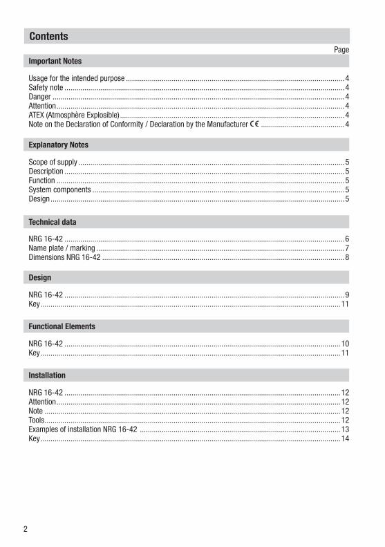
Contents
Usage for the intended purpose ..............................................................................................................4Safety note .............................................................................................................................................4Danger ...................................................................................................................................................4Attention .................................................................................................................................................4ATEX (Atmosphère Explosible) .................................................................................................................4Note on the Declaration of Conformity / Declaration by the Manufacturer ..........................................4
Important NotesPage
Explanatory Notes
Scope of supply ......................................................................................................................................5Description .............................................................................................................................................5Function .................................................................................................................................................5System components ...............................................................................................................................5Design ....................................................................................................................................................5
NRG 16-42 ...........................................................................................................................................12Attention ...............................................................................................................................................12Note .....................................................................................................................................................12Tools .....................................................................................................................................................12Examples of installation NRG 16-42 .....................................................................................................13Key .......................................................................................................................................................14
Installation
NRG 16-42 .............................................................................................................................................6Name plate / marking .............................................................................................................................7Dimensions NRG 16-42 ..........................................................................................................................8
Technical data
NRG 16-42 .............................................................................................................................................9Key .......................................................................................................................................................11
Design
NRG 16-42 ...........................................................................................................................................10Key .......................................................................................................................................................11
Functional Elements

3
Wiring
NRG 16-42 ...........................................................................................................................................15Aligning terminal box ............................................................................................................................15Note .....................................................................................................................................................15Wiring diagram .....................................................................................................................................16Attention ...............................................................................................................................................17Tools .....................................................................................................................................................17
Contents continued
Page
Basic Settings
CAN Bus ...............................................................................................................................................18Node ID ................................................................................................................................................18Attention ...............................................................................................................................................18Factory setting ......................................................................................................................................18Factory set default node IDs ..................................................................................................................19Assigning / changing node ID ................................................................................................................19Attention ...............................................................................................................................................19Code switch settings for node ID / baud rate .........................................................................................20
Commissioning
Check wiring ........................................................................................................................................21Apply mains voltage..............................................................................................................................21
Operation
Level electrode with CAN bus................................................................................................................21Note .....................................................................................................................................................21
Malfunctions
Fault finding list for troubleshooting ................................................................................................ 21-22
Decommissioning
Danger .................................................................................................................................................23Disposal................................................................................................................................................23

4
Important Notes
Danger
When loosening the electrode live steam or hot water might escape. This presents the danger of severe scalding. It is therefore essential not to dismantle the electrode unless the boiler pressure is verified to be zero.The electrode is hot during operation. This presents the risk of severe burns to hands and arms. Installation and maintenance work should only be carried out when the system is cold.If the internal ceramic insulation breaks, hot steam can escape through the lateral vent hole on the electrode body. This presents the risk of severe scalding. Do not stay near the electrode during operation.
Usage for the intended purpose
Use level electrode NRG 16-42 only in conjunction with level switch NRS 1-42.
Safety note
The equipment must only be installed and commissioned by qualified and adequately trained personnel.Maintenance and retrofitting must only by performed by entrusted personnel who – through adequate training – have achieved a recognised level of competence.
Attention
The name plate indicates the technical specification on the equipment. Do not commission or operate equipment without a name plate.
ATEX (Atmosphère Explosible)
According to the European Directive 2014/34/EU the equipment must not be used in explosion-risk areas.
Note on the Declaration of Conformity / Declaration by the Manufacturer
For details on the conformity assessment according to the European Directives see our Declaration of Conformity or our Declaration of Manufacturer.The current Declaration of Conformity / Declaration of Manufacturer are available in the Internet under www.gestra.de/document or can be requested from us.

5
Explanatory Notes
Scope of supply
NRG 16-421 Level electrode type NRG 16-42 1 Joint ring (of stainless steel 1.4301) D 33 x 39 to DIN 7603, bright annealed1 Terminating resistor 120 Ω1 Installation manual
Description
The level electrode NRG 16-42 works according to the conductivity measurement principle. With the NRG 16-42 a maximum of 4 levels can be signalled in conductive liquids: 4 levels with one switchpoint each. High level (MAX) alarm, Low level (MIN) alarm, pump ON, pump OFF with one switchpoint each.Use level electrode NRG 16-42 in combination with level switch type NRS 1-42 or further system components. The level data are transferred to the level switch or another system component via CAN data bus, using the CANopen protocol.
System components
NRS 1-42Data exchange: CAN bus to DIN ISO 11898, using CANopen protocol.
URB 1, URB 2Control terminal & display unit.Functions: Parameterization and visual display (LCD).Data exchange: CAN bus to DIN ISO 11898, using CANopen protocol.
Design
NRG 16-42:Screwed design 1" BSP, EN ISO 228-1. Fig. 2
Function
The conductivity of the liquid is used to signal the liquid level. Some liquids are conductive, which means that they allow an electric current to flow through them. For the safe functioning of this device a minimum conductivity of the liquid to be measured is required.The conductivity measurement method can detect two conditions: electrode rod submerged or exposed, meaning switchpoint reached (or exceeded) or not yet reached. Before installation, the length of the electrode rod must be cut to the required switching levels, e. g. for max./min. alarm, controlling of a valve or pump.At regular intervals the level electrode NRG 16-42 sends a data telegram to the level switch NRS 1-42. The data are transferred via a CAN bus to DIN ISO 11898 using the CANopen protocol.
6
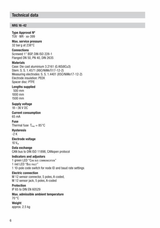
NRG 16-42
Type Approval Nº TÜV · WR · xx-399Max. service pressure 32 bar g at 238°CConnections Screwed 1" BSP, DIN ISO 228-1 Flanged DN 50, PN 40, DIN 2635Materials Case: Die cast aluminium 3.2161 (G AlSi8Cu3) Stem: S. S. 1.4571 (X6CrNiMoTi17-12-2)Measuring electrodes: S. S. 1.4401 (X5CrNiMo17-12-2)Electrode insulation: PEEK Spacer disc: PTFELengths supplied 500 mm1000 mm1500 mm
Supply voltage 18 – 36 V DCCurrent consumption 65 mAFuse Thermal fuse Tmax = 85°CHysteresis -2 K Electrode voltage10 Vss
Data exchange CAN bus to DIN ISO 11898, CANopen protocolIndicators and adjustors1 green LED “Can bus CommuniCation” 1 red LED “bus fault” 1 10-pole code switch for node ID and baud rate settingsElectric connection M 12 sensor connector, 5 poles, A-coded, M 12 sensor jack, 5 poles, A-codedProtection IP 65 to DIN EN 60529Max. admissible ambient temperature 70 °CWeight approx. 2.5 kg
Technical data
7
Technical Data continued
Name plate / marking
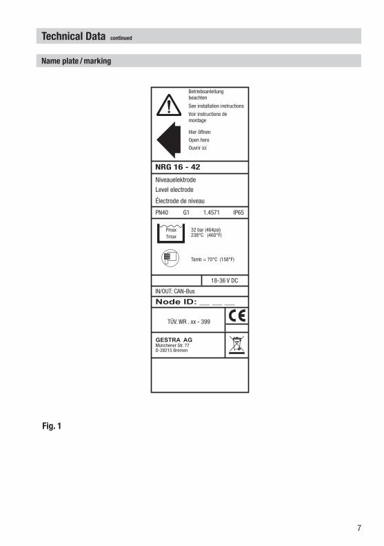
Fig. 1
Betriebsanleitungbeachten
See installation instructions
Hier öffnen
Open here
Ouvrir ici
Voir instructions demontage
18-36 V DC
Tamb = 70°C (158°F)
IN/OUT: CAN-Bus
PmaxTmax
NRG 16 - 42
PN40 G1 1.4571 IP65
32 bar (464psi)238°C (460°F)
Node ID: __ __ __
GESTRA AGMünchener Str. 77D-28215 Bremen
TÜV. WR . xx - 399
Niveauelektrode
Level electrode
Électrode de niveau

8
4 3
GESTRA Steam Systems
GESTRANRG 16-42
4
3
12
Fig. 2
Technical Data continued
Dimensions NRG 16-42
175
Depth: 70mm
140
337.5
500,
100
0, 1
500
9
Design
NRG 16-42
2 14 3
GESTRA Steam Systems
GESTRANRG 16-42
Fig. 3 Fig. 4
N10
0.51" BSP, ISO 228-1
∅ 40
50 65-7
0≥14
BA
C
D

10
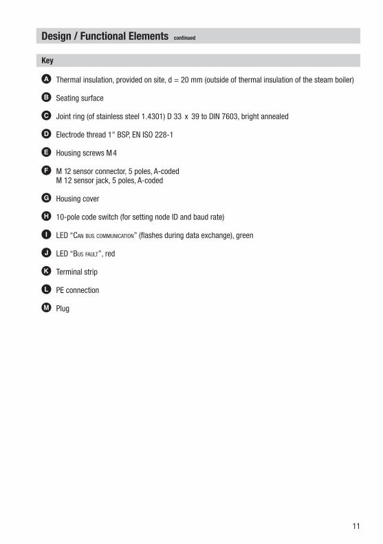
Functional Elements
NRG 16-42
1 2 3 4 5
1 098765432
NO
GESTRA Steam Systems
GESTRANRG 16-42
Fig. 5
Fig. 6
E
M
L K
H
IJ
F G F
11
A Thermal insulation, provided on site, d = 20 mm (outside of thermal insulation of the steam boiler)
B Seating surface
C Joint ring (of stainless steel 1.4301) D 33 x 39 to DIN 7603, bright annealed
D Electrode thread 1" BSP, EN ISO 228-1
E Housing screws M4
F M 12 sensor connector, 5 poles, A-coded M 12 sensor jack, 5 poles, A-coded
G Housing cover
H 10-pole code switch (for setting node ID and baud rate)
I LED “Can bus CommuniCation” (flashes during data exchange), green
J LED “bus fault”, red
K Terminal strip
L PE connection
M Plug
Design / Functional Elements continued
Key
12
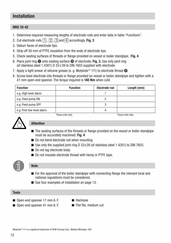
Function Function Electrode rod Length [mm]
e.g. High level alarm 1
e.g. Feed pump ON 2
e.g. Feed pump OFF 3
e.g. First low-level alarm 4
Attention
The seating surfaces of the threads or flange provided on the vessel or boiler standpipe must be accurately machined. Fig. 4
Do not bend electrode rod when mounting. Use only the supplied joint ring D 33x39 (of stainless steel 1.4301) to DIN 7603. Do not lag electrode body. Do not insulate electrode thread with hemp or PTFE tape.
Installation
NRG 16-42
Molykote® 111 is a registered trademark of DOW Corning Corp., Midland Michigan, USA
1. Determine required measuring lengths of electrode rods and enter data in table “Functions”.2. Cut electrode rods , , and accordingly, Fig. 33. Deburr faces of electrode tips.4. Strip off 50 mm of PTFE insulation from the ends of electrode tips.5. Check seating surfaces of threads or flange provided on vessel or boiler standpipe, Fig. 46. Place joint ring C onto seating surface B of electrode, Fig. 3. Use only joint ring
(of stainless steel 1.4301) D 33 x 39 to DIN 7603 supplied with electrode.7. Apply a light smear of silicone grease (e. g. Molykote ® 111) to electrode thread D.8. Screw level electrode into threads or flange provided on vessel or boiler standpipe and tighten with a
41 mm open-end spanner. The torque required is 140 Nm when cold.
Please enter data.Please enter data.
Note
For the approval of the boiler standpipe with connecting flange the relevant local and national regulations must be considered.
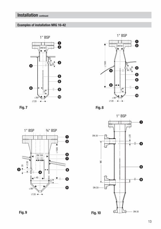
See four examples of installation on page 13.
Tools
Open-end spanner 17 mm A. F. Open-end spanner 41 mm A. F.
Hacksaw Flat file, medium cut
1 2 3 4
13
12
Installation continued
Examples of installation NRG 16-42
Fig. 7
Fig. 9
DN 50
20∅
20
1" BSP
≥10
≤90°
∅20
20
∅ 2
0
≥10
≤90°∅20
DN 50
1" BSP
Fig. 8
9
DN 20
DN 20
≥20
1" BSP
Fig. 10 DN 20
1" BSP ¾" BSP
DN 100
20 ∅20
≤90°
∅20
24,5 24,5
≥10
≤15
00
ME
≤15
00
> 40
12
3
56
9
0
8
4
12
3
56
9
0
4
8
12
57
8
9
!
43
1
4
5
9

14
1 Flange PN 40, DN 50 (2"), DIN 2527 Flange PN 40, DN 100 (4"), DIN 2527
2 For the approval of the boiler standpipe with connecting flange the relevant regulations must be considered.
3 Vent hole Provide vent hole as close as possible to the boiler wall.
4 High water (HW)
5 Electrode rod d = 5 mm
6 Protection tube DN 80
7 Protection tube DN 100
8 Electrode distance ≥ 14 mm
9 Low water (LW)
0 Reducer K-88.9 x 3.2 – 42.4 x 2.6 W to DIN 2616, part 2
! Reducer K-114.3 x 3.6 – 48.3 x 2.9 W to DIN 2616, part 2
Installation continued
Key
15
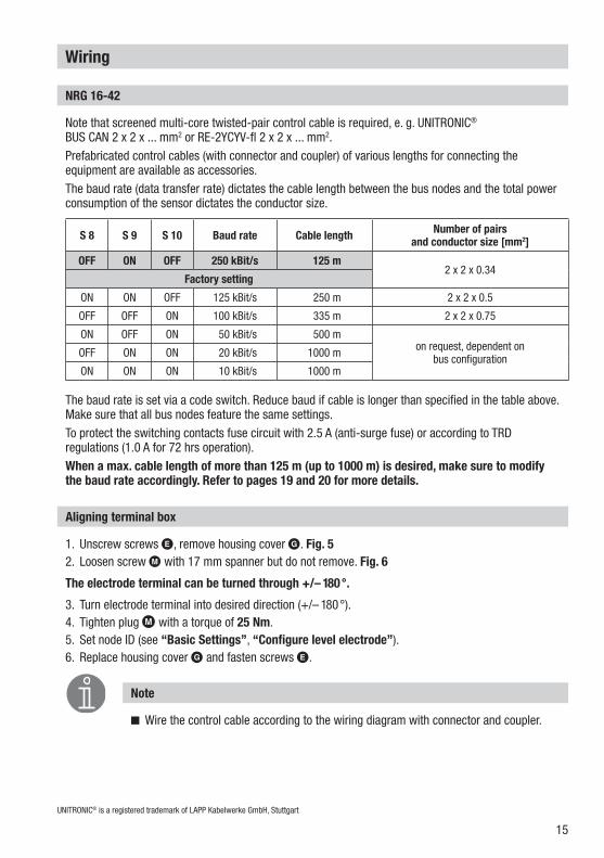
1. Unscrew screws E, remove housing cover G. Fig. 52. Loosen screw M with 17 mm spanner but do not remove. Fig. 6
The electrode terminal can be turned through +/– 180°.
3. Turn electrode terminal into desired direction (+/– 180°).4. Tighten plug M with a torque of 25 Nm.5. Set node ID (see “Basic Settings”, “Configure level electrode”).6. Replace housing cover G and fasten screws E.
Wiring
NRG 16-42
Note that screened multi-core twisted-pair control cable is required, e. g. UNITRONIC® BUS CAN 2 x 2 x ... mm2 or RE-2YCYV-fl 2 x 2 x ... mm2.Prefabricated control cables (with connector and coupler) of various lengths for connecting the equipment are available as accessories.The baud rate (data transfer rate) dictates the cable length between the bus nodes and the total power consumption of the sensor dictates the conductor size.
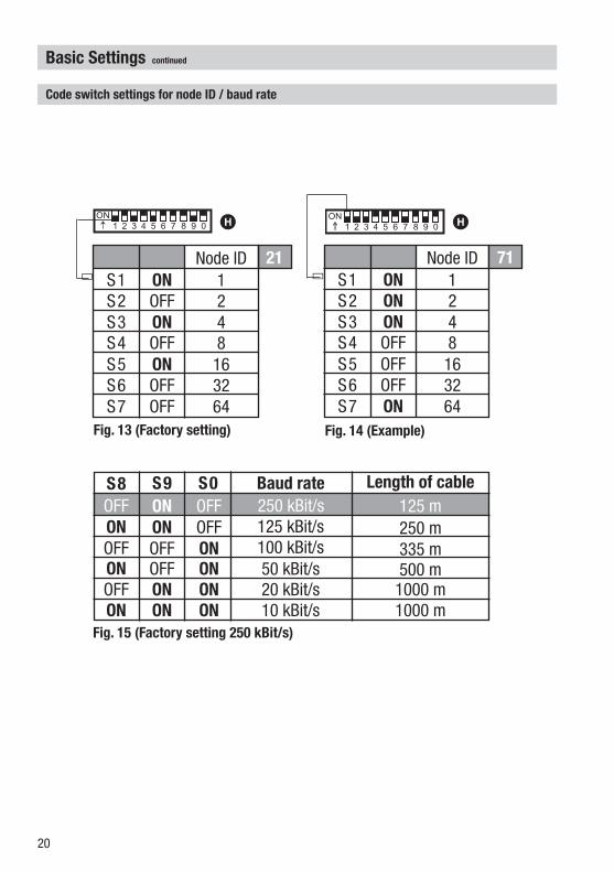
The baud rate is set via a code switch. Reduce baud if cable is longer than specified in the table above. Make sure that all bus nodes feature the same settings.To protect the switching contacts fuse circuit with 2.5 A (anti-surge fuse) or according to TRD regulations (1.0 A for 72 hrs operation).When a max. cable length of more than 125 m (up to 1000 m) is desired, make sure to modify the baud rate accordingly. Refer to pages 19 and 20 for more details.
UNITRONIC® is a registered trademark of LAPP Kabelwerke GmbH, Stuttgart
S 8 S 9 S 10 Baud rate Cable length Number of pairs and conductor size [mm2]
OFF ON OFF 250 kBit/s 125 m2 x 2 x 0.34
Factory setting
ON ON OFF 125 kBit/s 250 m 2 x 2 x 0.5
OFF OFF ON 100 kBit/s 335 m 2 x 2 x 0.75
ON OFF ON 50 kBit/s 500 mon request, dependent on
bus configurationOFF ON ON 20 kBit/s 1000 m
ON ON ON 10 kBit/s 1000 m
Aligning terminal box
Note
Wire the control cable according to the wiring diagram with connector and coupler.

16
1
2
3
4
NRG 16-42
_
1 2 3 4 5
S +
CL HC
24V DC
CAN - Bus
S
1 098765432
NO
CL CH
Wiring continued
Wiring diagram
UNITRONIC® is a registered trademark of LAPP Kabelwerke GmbH, Stuttgart
e.g. UNITRONIC® BUS CAN 2 x 2 x...2
e.g. UNITRONIC® BUS CAN 2 x 2 x...2
Fig. 11
Electrode rod
Electrode rod
Electrode rod
Code switch
Terminating resistor 120 Ω, paired cable.
3
5 5 5 555
+- LC HCS
Coupler with terminating resistor 120 Ω
Operating device URB 1
CEPCentralearthingpoint
Connector with terminating resistor 120 Ω
ControllerNRS ...LRR ...TRS ...
Level electrodeConductivity electrodeNRG ...LRG ...
Temperature transmitterTRV ...
2 1 54634 1 52 1 Screen
2 Voltage supply 24V DC+
3 Voltage supply 24V DC-
4 CAN Data line CH
5 CAN Data line CL
6 Terminating resistor 120 Ω
Electrode rod

17
Wire equipment in series. Star-type wiring is not permitted! Interlink screens of control cables such that electrical continuity is ensured and
connect them once to central earthing point (CEP). In a CAN bus network the first and the last equipment must be provided with a
terminating resistor of 120 Ω. Fig. 11 The CAN bus network mut not be interrupted while operating. An interruption will result in high/low level alarm!
Tools
Attention
Screwdriver for cross head screws, size 1 Screwdriver for slotted screws, size 2.5, completely insulated according to VDE 0680 Open-end spanner 17 mm A. F.
Wiring continued
18
Basic Settings
CAN bus
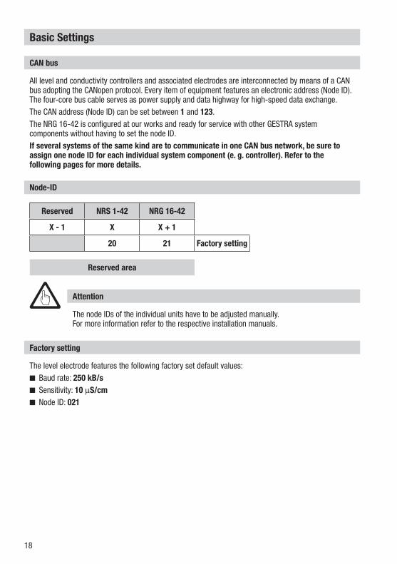
All level and conductivity controllers and associated electrodes are interconnected by means of a CAN bus adopting the CANopen protocol. Every item of equipment features an electronic address (Node ID). The four-core bus cable serves as power supply and data highway for high-speed data exchange.The CAN address (Node ID) can be set between 1 and 123.The NRG 16-42 is configured at our works and ready for service with other GESTRA system components without having to set the node ID.If several systems of the same kind are to communicate in one CAN bus network, be sure to assign one node ID for each individual system component (e. g. controller). Refer to the following pages for more details.
The node IDs of the individual units have to be adjusted manually. For more information refer to the respective installation manuals.
Node-ID
Factory setting
The level electrode features the following factory set default values:Baud rate: 250 kB/s Sensitivity: 10 µS/cmNode ID: 021
Attention
Reserved NRS 1-42 NRG 16-42
X - 1 X X + 1
20 21 Factory setting
Reserved area
19
1 2 3 4 5
1 098765432
NO
Fig. 12
H
Basic Settings continued
Attention
Do not assign the same node ID twice within the CAN bus network.
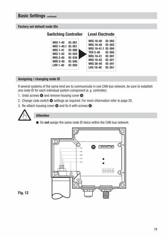
Assigning / changing node ID
If several systems of the same kind are to communicate in one CAN bus network, be sure to establish one node ID for each individual system component (e. g. controller).1. Undo screws E and remove housing cover G.2. Change code switch H settings as required. For more information refer to page 20.3. Re-attach housing cover G and fix it with screws E.
Factory set default node IDs
NRS 1-40 ID: 001
NRS 1-40.1 ID: 001
NRS 1-41 ID: 006
NRS 1-42 ID: 020
NRS 2-40 ID: 039
NRR 2-40 ID: 040
LRR 1-40 ID: 050
NRG 16-40 ID: 002
NRG 16-40 ID: 003
NRG 16-41.1 ID: 004
TRV 5-40 ID: 005
NRG 16-41 ID: 007
NRG 16-42 ID: 021
NRG 26-40 ID: 041
LRG 16-40 ID: 051
Switching Controller Level Electrode
20
1 098765432
NO
1 098765432
NO
Basic Settings continued
Code switch settings for node ID / baud rate
Fig. 13 (Factory setting) Fig. 14 (Example)
Fig. 15 (Factory setting 250 kBit/s)
ONNode ID
S1 1ONS2 2ONS3 4OFFS4 8OFFS5 16OFFS6 32ONS7 64
ONNode ID
S1 1OFFS2 2ONS3 4OFFS4 8ONS5 16OFFS6 32OFFS7 64
21 71
Baud rateS8 S9 S0250 kBit/s
Length of cable125 mOFFONOFF
OFF 125 kBit/sONON 250 mON 100 kBit/sOFFOFF 335 mON 50 kBit/sOFFON 500 mON 20 kBit/sONOFF 1000 mON 10 kBit/sONON 1000 m
H H
21
Turn on the power for level switch NRS 1-42.
Commissioning
Check whether the level electrode NRG 16-42 and the associated level switch NRS 1-42 have been wired according to the wiring diagram. Fig. 11
Check wiring
Apply mains voltage
Operation
During operation the level switch detects the level electrode via CAN bus.The communication via CAN bus is faultless – there are no fault messages.
Level electrode with CAN bus
Note
To analyse and eliminate malfunctions refer to “Fault finding list for troubleshooting” on pages 21 - 22.
Malfunctions
Fault finding list for troubleshooting
Fault: In spite of correct wiring and commissioning of the equipment an interference signal is indicated.
Remedy: The interference signal is caused by H. F. interferences coming from the installation. For interference suppression of the voltage supply we supply ferrite rings, stock code 147253. The 230 V supply lines should be looped through the ferrite ring five to ten times. If several controllers are used in the system, they can be fed from the interference suppressed supply lines. For the interference suppression of the bus line we supply hinged-shell ferrite rings, stock code 147254. The hinged-shell ferrite rings are clamped onto the bus line close to the terminal strip of the controller.
Equipment fails to work – Indication of a malfunction
22
Malfunctions continued
Fault finding list for troubleshooting continued
Fault: The thermal fuse has been triggered.Remedy: The ambient temperature must not exceed 70°C.
Fault: The LED I does not light up. No data exchange.Remedy: Check level switch NRS 1-42. Connect electode according to the wiring diagram.
The equipment fails to work – no function
Fault: LED “Power” does not light up.Remedy: Apply mains voltage. Wire equipment according to the wiring diagram.
Switchpoints reached / level below switchpoints – no function
Fault: The electrode housing does not have earth connection to the boiler.Remedy: Clean seating surfaces and insert metal joint ring (of stainless steel 1.4301) 33 x 39 to
DIN 7603. Do not insulate compact system with hemp or PTFE tape!
Fault: The electric conductivity is too low.Remedy: Set sensitivity of level switch NRS 1-42 to ≥ 0.5 µS/cm.
Fault: The isolating valves of the external measuring pot (optional) are closed.Remedy: Open isolating valves.
Fault: The vent hole in the protection tube does not exist, is obstructed or flooded.Remedy: Check protection tube and, if necessary, provide vent hole.
Fault: The electrode rods have earth contact.Remedy: Change installation position.
Fault: The switching function has not been correctly allocated. Electrode rods have been cut to the wrong size.
Remedy: Identify electrode supply wire and reconnect the circuit board in the terminal box accordingly.
Switchpoints reached / level below switchpoints – incorrect function
If faults occur that are not listed above or cannot be corrected, please contact our service centre or authorized agency in your country.
Fault: The internal seal of the electrode rod is damaged.Remedy: Replace level electrode.

23
Decommissioning
Danger
Risk of severe burns and scalds to the whole body!Before removing the level electrode make sure that the vessel and the measuring pot are depressurised (O bar) and cooled down to room temperature (20 °C).
Remove the level electrode and separate the waste materials, using the material specifications as a reference. Electronic components (circuit boards) must be disposed of properly.For the disposal of the level electrode observe the pertinent legal regulations concerning waste disposal.
Disposal
24810295-04/07-2017cm (808458-06) · GESTRA AG · Bremen · Printed in Germany
Agencies all over the world:
www.gestra.de
GESTRA AGMünchener Straße 77 28215 BremenGermanyTelefon +49 421 3503-0 Telefax +49 421 3503-393E-mail [email protected] www.gestra.de