GESTRA Steam Systems - Flowserve · GESTRA Steam Systems ... Data exchange: CAN bus to DIN ISO 898,...
28
NRG 26-40 Installation Instructions 810274-02 Level electrode NRG 26-40 GESTRA Steam Systems GESTRA
Transcript of GESTRA Steam Systems - Flowserve · GESTRA Steam Systems ... Data exchange: CAN bus to DIN ISO 898,...

NRG26-40InstallationInstructions810274-02Level electrode NRG 26-40
GESTRASteamSystems
GESTRA

2
Contents
Usage for the intended purpose ..............................................................................................................4Safety note .............................................................................................................................................4Danger ...................................................................................................................................................4Attention .................................................................................................................................................4ATEX (Atmosphère Explosible) .................................................................................................................4
ImportantNotesPage
ExplanatoryNotes
Scope of supply ......................................................................................................................................4Description .............................................................................................................................................5Function .................................................................................................................................................5System components ...............................................................................................................................5Design ....................................................................................................................................................5
NRG 26-40 ...........................................................................................................................................2Attention ...............................................................................................................................................2Note .....................................................................................................................................................2Tools .....................................................................................................................................................2Examples of installation NRG 26-40 .....................................................................................................3Key .......................................................................................................................................................4
Installation
NRG 26-40 .............................................................................................................................................6Corrosion resistance ...............................................................................................................................7Sizing .....................................................................................................................................................7Name plate / marking .............................................................................................................................7Dimensions NRG 26-40 ..........................................................................................................................8
Technicaldata
NRG 26-40 .............................................................................................................................................9Key .......................................................................................................................................................
Design
NRG 26-40 ...........................................................................................................................................0Key .......................................................................................................................................................
FunctionalElements
3
Wiring
NRG 26-40 ...........................................................................................................................................5Aligning terminal box ............................................................................................................................5Note .....................................................................................................................................................5Wiring diagram .....................................................................................................................................6Attention ...............................................................................................................................................7Tools .....................................................................................................................................................7
Contentscontinued
Page
BasicSettings
CAN Bus ...............................................................................................................................................8Node ID ................................................................................................................................................8Attention ...............................................................................................................................................8Factory setting ......................................................................................................................................8Factory set default node IDs ..................................................................................................................9Assigning / changing node ID ................................................................................................................9Attention ...............................................................................................................................................9Code switch settings .............................................................................................................................20Measuring range ...................................................................................................................................2
Commissioning
Check wiring ........................................................................................................................................22Apply mains voltage..............................................................................................................................22
Operation
Level electrode with CAN bus................................................................................................................22Note .....................................................................................................................................................22Adjusting the attenuation of the level controller ............................................................................... 22-23
Malfunctions
Fault finding list for troubleshooting ................................................................................................ 23-24
Decommissioning
Danger .................................................................................................................................................25Disposal................................................................................................................................................25
Annex
Declaration of conformity ......................................................................................................................25

4
ImportantNotes
Danger
When loosening the electrode live steam or hot water might escape. This presents the danger of severe scalding. It is therefore essential not to dismantle the electrode unless the boiler pressure is verified to be zero.The electrode is hot during operation. This presents the risk of severe burns to hands and arms. Installation and maintenance work should only be carried out when the system is cold.If the internal ceramic insulation breaks, hot steam can escape through the lateral vent hole on the electrode body. This presents the risk of severe scalding. Do not stay near the electrode during operation.
Usagefortheintendedpurpose
Use level electrode NRG 26-40 only in conjunction with switching controller NRS 2-40 or level controller NRR 2-40 for level indication in electrically conductive or non-conductive liquids.
Safetynote
The equipment must only be installed and commissioned by qualified and adequately trained personnel.Maintenance and retrofitting must only by performed by entrusted personnel who – through adequate training – have achieved a recognised level of competence.
Attention
The name plate indicates the technical specification of the equipment. Do not commission or operate equipment without a name plate.
ATEX(AtmosphèreExplosible)
According to the European Directive 94/9/EC the equipment must not be used in explosion-risk areas.
ExplanatoryNotes
Scopeofsupply
NRG26-40 Level electrode type NRG 26-40 Joint ring (of stainless steel .430) D 27 x 32 to DIN 7603, bright annealed Terminating resistor 20 Ω Installation manual

5
ExplanatoryNotescontinued
Description
The level electrode NRG 26-40 works according to the capacitance measurement principle. The NRG 26-40 is used for signalling different levels in conductive and non-conductive liquids: Water level maintained within the control band defined by two preset limits.
Use level electrode NRG 26-40 in combination with level switch type NRS 2-40 or further system components. The level data are transferred to the level switch or another system component via the CAN data bus, adopting the CANopen protocol.
Systemcomponents
NRS2-40Digital switching controller for level electrodes type NRG 26-40.Functions: Four liquid levels with one switchpoint each, MAX alarm, MIN alarm, pump ON, pump OFF with one switchpoint each, water level continuously within the predefined control band.Data exchange: CAN bus to DIN ISO 898, using CANopen protocol.NRR2-40Digital level controller for level electrodes type NRG 26-40.Functions: Four liquid levels with one switchpoint each, MAX alarm, MIN alarm, pump ON, pump OFF with one switchpoint each, water level continuously within the predefined control band.Data exchange: CAN bus to DIN ISO 898, using CANopen protocol.URB1,URB2Control terminal & display unit.Functions: Parameterization and visual display (LCD).Data exchange: CAN bus to DIN ISO 898, using CANopen protocol.
Design
NRG26-40:Screwed design ¾" BSP, EN ISO 228-. Fig.2
Function
The principle of capacitance measurement is applied to determine the level. The electrode rod and the vessel wall form the plates of a capacitor. If the level of the dielectric located between these two capacitor plates changes, the current which flows through the plates changes proportionally to the level. A dielectric is by definition an insulating substance, which excludes many liquids such as water. In order to receive a useful measuring result the measuring rod, which is submerged to varying depths in the liquid, must be completely insulated. After the calibration of the zero point/measuring range (0 %/00 %) the level can be read off from a remote display unit. The level measuring range can be changed during operation.At regular intervals the level electrode NRG 26-40 sends a data telegram to the level switch NRS 2-40 or level controller NRR 2-40. The data transfer is effected by means of a CAN bus according to DIN ISO 898 using the CANopen protocol.
6
NRG26-40
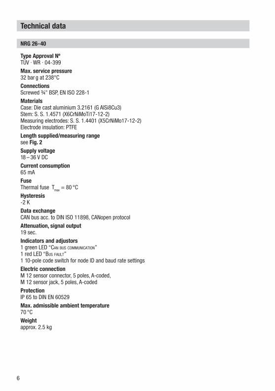
TypeApprovalNºTÜV · WR · 04-399Max.servicepressure32 bar g at 238°CConnectionsScrewed ¾" BSP, EN ISO 228-MaterialsCase: Die cast aluminium 3.26 (G AlSi8Cu3) Stem: S. S. .457 (X6CrNiMoTi7-2-2)Measuring electrodes: S. S. .440 (X5CrNiMo7-2-2)Electrode insulation: PTFELengthsupplied/measuringrangesee Fig.2Supplyvoltage8 – 36 V DCCurrentconsumption65 mAFuseThermal fuse Tmax = 80 °CHysteresis-2 K DataexchangeCAN bus acc. to DIN ISO 898, CANopen protocolAttenuation,signaloutput 9 sec.Indicatorsandadjustors green LED “Can bus CommuniCation” red LED “bus fault” 0-pole code switch for node ID and baud rate settingsElectricconnectionM 2 sensor connector, 5 poles, A-coded, M 2 sensor jack, 5 poles, A-codedProtectionIP 65 to DIN EN 60529Max.admissibleambienttemperature70 °CWeightapprox. 2.5 kg
Technicaldata

7
Technicaldatacontinued
Corrosionresistance
When used for its intended purpose the safe functioning of the electrode will not be impaired by corrosion.
Sizing
The electrode body must not be subjected to sharp increases in pressure. Welds and flanges of the electrode are designed to withstand dynamic loading (bending and alternating stress). The dimensional allowances for corrosion reflect the latest state of technology.
Nameplate / marking
H= mm
GESTRA AGMünchener Str. 77D-28215 Bremen
18-36 V DC
Betriebsanleitungbeachten!
See installation instructions!
Voir instructions demontage!
Tmax = 70°C (158 °F)
IN/OUT: CAN-Bus
TÜV.WR. 04 - 399
PmaxPmaxTmaxTmax
NRG 26 - 40
PN40 G3/4 NPT 1.4571 IP65
NiveauelektrodeLevel electrodeÉlectrode de niveau
32 bar (464psi)
238°C (460°F)
Node ID: __ __ __
VS-Nr.: Mat-Nr.:391798
Designation of the equipment
Fig.1

8
Fig.2
Technicaldatacontinued
DimensionsNRG26-40
GESTRA Steam Systems
GESTRANRG 26-40
¾" EN ISO 228-
40
337.5
73
3726
Depth: 70 mm
1 2
300400500600700800900000002003004005002000
37347758368879489900402439423528636256
1 2
3
9
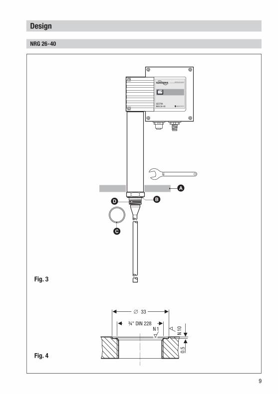
Design
NRG26-40
Fig.3
Fig.4
B
GESTRA Steam Systems
GESTRANRG 26-40
N
N0
0.5
∅ 33
¾" DIN 228
AD
C
B
0
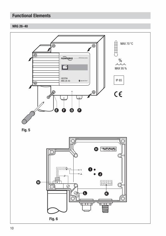
FunctionalElements
NRG26-40
H
1
1 2 3 5 6 74 8 910
ON
1 2 3 4 5
MAX 70 °C
MAX 95%
%
IP 65
GESTRA Steam Systems
GESTRANRG 26-40
Fig.5
MAX 70 °C
MAX 95 %
Fig.6
E
M
L K
H
IJ
F G F

A Thermal insulation, provided on site, d = 20 mm (outside of thermal insulation of steam generating unit)
B Seating surface
C Joint ring (of stainless steel .430) D 33 x 39 to DIN 760, bright annealed
D Electrode thread ¾", EN ISO 228-
E Housing screws M4
F M 2 sensor connector, 5 poles, A-coded, M 2 sensor jack, 5 poles, A-coded
G Housing cover
H 0-pole code switch (for setting node ID and baud rate)
I Green LED “Can bus CommuniCation”
J Red LED “Bus fault”
K Terminal strip
L PE connection
M Plug
1 Max. length of installation at 238 °C
2 Measuring range
3 Adjustable control range
Design/FunctionalElementscontinued
Key

2
Attention
The seating surfaces of the threads or flange provided on the vessel or boiler standpipe must be accurately machined. Fig.4
Do not bend electrode rod when mounting. Use only joint ring (of S.S. type .430) D 33 x 39 to DIN 7603 supplied with electrode. Electrode body must not be included in the thermal insulation of the steam boiler. Do not insulate electrode thread with hemp or PTFE tape.
Installation
NRG26-40
Note
For the approval of the boiler standpipe with connecting flange the relevant local or national regulations must be considered. See four examples of installation on page 3.
Tools
Open-end spanner mm A. F. 8 Open-end spanner mm A. F. 4
Molykote® is a registered trademark of DOW Corning Corp., Midland Michigan, USA
. Check seating surfaces of threads or flange provided on vessel or boiler standpipe. Fig.42. Place joint ring C onto seating surface B of the electrode Fig.3.3. Apply a light smear of silicone grease (e. g. Molykote ) to electrode thread D.4. Screw level electrode into threads or flange provided on vessel or boiler standpipe and tighten with a 4 mm open-end spanner. The torque required is 160Nm when cold.5. When mounting two electrodes in one flange install the first electrode as described under item 4. Before installing the second electrode loosen the plug M, unscrew PE connection and remove cable connectors from circuit board. Screw in electrode. Slightly tighten plug M. Install PE connection L, fix cable connectors.
3
Installationcontinued
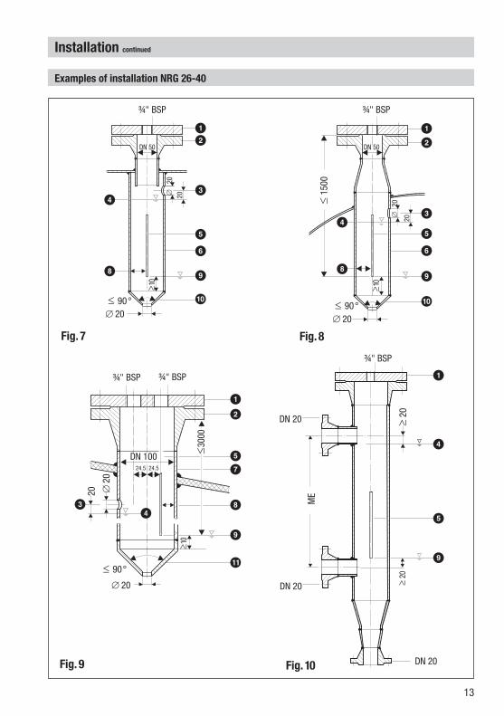
ExamplesofinstallationNRG26-40
Fig.7
Fig.9
Fig.8
Fig.10
1
∅
2020
DN 50
¾" BSP
≥0
∅ 20≤ 90°
DN 20
DN 20
¾" BSP
≥ 20
DN 20
≥ 20
ME
12
DN 0024.5 24.5
20 ∅20
¾" BSP
∅ 20
¾" BSP
≤ 90°
≥0
≤ 300
0
5
6
4
DN 50
¾" BSP
∅
20
≥0
∅ 20≤ 90°
≤ 5
00
20
12
3
56
9
0
4
8
12
356
9
0
4
8
1
4
5
9
12
57
8
9
!
43

4
1Flange PN 40, DN 50 (2"), DIN 2527 Flange PN 40, DN 00 (4"), DIN 2527
2For the approval of the boiler standpipe with connecting flange the relevant regulations must be considered.
3Vent hole Provide vent hole as close as possible to the boiler wall.
4High water (HW)
5Electrode rod d = 5 mm
6Protection tube DN 80
7Protection tube DN 00
8Electrode distance ≥ 4 mm
9Low water (LW)
0Reducer K-88.9 x 3.2-42.4 x 2.6 W to DIN 266, part 2!
!Reducer K-4.3 x 3.6-48.3 x 2.9 W to DIN 266, part 2
Installationcontinued
Key

5
. Unscrew screws E, remove housing cover G. Fig.52. Loosen screw M with 7 mm spanner but do not remove. Fig.6
Theelectrodeterminalcanbeturnedthrough+/– 180°.
3. Turn electrode terminal into desired direction (+/– 80°).4. Tighten plug M with a torque of 25Nm.5. Set node ID (see “BasicSettings”, “Configurelevelelectrode”).6. Replace housing cover G and fasten screws E.
Wiring
NRG26-40
Note that screened multi-core twisted-pair control cable is required, e. g. UNITRONIC® BUS CAN 2 x 2 x ... mm2 or RE-2YCYV-fl 2 x 2 x ... mm2.Prefabricated control cables (with connector and coupler) of various lengths for connecting the equipment are available as accessories.The baud rate (data transfer rate) dictates the cable length between the bus nodes and the total power consumption of the sensor dictates the conductor size.
The baud rate is set via a code switch. Reduce baud if cable is longer than specified in the table above. Make sure that all bus nodes feature the same settings.To protect the switching contacts fuse circuit with 2.5 A (anti-surge fuse) or according to TRD regulations (.0 A for 72 hrs operation).Whenamax.cablelengthofmorethan125m(upto1000m)isdesired,makesuretomodifythebaudrateaccordingly.Refertopages19and20formoredetails.
UNITRONIC® is a registered trademark of LAPP Kabelwerke GmbH, Stuttgart
S8 S9 S10 Baudrate Cablelength Numberofpairsandconductorsize[mm2]
OFF ON OFF 250kBit/s 125m2 x 2 x 0.34
Factorysetting
ON ON OFF 25 kBit/s 250 m 2 x 2 x 0.5
OFF OFF ON 00 kBit/s 335 m 2 x 2 x 0.75
ON OFF ON 50 kBit/s 500 mon request, dependent on
bus configurationOFF ON ON 20 kBit/s 000 m
ON ON ON 0 kBit/s 000 m
Aligningterminalbox
Note
Wire the control cable according to the wiring diagram with connector and coupler.

6
NRG 26-40
_
1 2 3 4 5
C L S C H +
C L HC
1
1 2 3 5 6 74 8 910ON
24V DC
CAN - Bus
S
Wiringcontinued
Wiringdiagram
UNITRONIC® is a registered trademark of LAPP Kabelwerke GmbH, Stuttgart
e.g. UNITRONIC® BUS CAN 2 x 2 x...2
e.g. UNITRONIC® BUS CAN 2 x 2 x...2
Fig.11
Electrode rod
Code switch
Terminating resistor 20 Ω, paired cable.
3
5 5 5 555
+- LC HCS
Coupler with terminating
resistor 20 Ω
Operating device URB
CEPCentralearthingpoint
Connector with terminating
resistor 20 Ω
ControllerNRS ...LRR ...TRS ...
Level electrodeConductivity electrodeNRG ...LRG ...
Temperature transmitterTRV ...
2 1 54634 1 52 1 Screen
2 Voltage supply 24V DC+
3 Voltage supply 24V DC-
4 CAN Data line CH
5 CAN Data line CL
6 Terminating resistor 20 Ω
7
Wire equipment in series. Star-type wiring is not permitted! Interlink screens of control cables such that electrical continuity is ensured and
connect them once to central earthing point (CEP). In a CAN bus network the first and the last equipment must be provided with a
terminating resistor of 20 Ω. Fig.11 The CAN bus network mut not be interrupted while operating. Aninterruptionwillresultinhigh/lowlevelalarm.
Tools
Attention
Screwdriver for cross head screws, size Screwdriver for slotted screws, size 2.5, completely insulated according to VDE 0680 Open-end spanner 7 mm A. F.
Wiringcontinued

8
The node IDs of the individual devices have to be adjusted manually. For more information refer to the respective installation manuals.
BasicSettings
CANBus
All level and conductivity controllers and associated electrodes are interconnected by means of a CAN bus adopting the CANopen protocol. Every item of equipment features an electronic address (Node ID). The four-core bus cable serves as power supply and data highway for high-speed data exchange.The CAN address (Node ID) can be set between 1 and 123.The NRG 26-40 is configured at our works and ready for service with other GESTRA system components without having to set the node ID.IfseveralsystemsofthesamekindaretocommunicateinoneCANbusnetwork,besuretoassignonenodeIDforeachindividualsystemcomponent(e.g.controller).Refertothefollowingpagesformoredetails.
NodeID
Factorysetting
The level electrode features the following factory set default values: Baud rate: 250kB/s Sensitivity: 10µS/cmNode ID: 041
Attention
Reserved NRS 2-40 NRR 2-40 NRG 26-40 Reserved
X - 2 X - X X + X + 2
39 40 4 Factory setting
Reserved area

9
BasicSettingscontinued
H
1
1 2 3 5 6 74 8 910
ON
1 2 3 4 5
Fig.12
Attention
Do not assign the same node ID twice within the CAN bus network.
Assigning/changingnodeID
If several systems of the same kind are to communicate in one CAN bus network, be sure to establish one node ID for each individual system component (e. g. controller).. Undo screws E and remove housing cover G.2. Change code switch H settings as required. For more information refer to page 20.3. Re-attach housing cover G and fix it with screws E.
H
FactorysetdefaultnodeIDs
NRS 1-40 ID: 001NRS 1-40.1 ID: 001NRS 1-41 ID: 006NRS 1-42 ID: 020NRS 2-40 ID: 039NRR 2-40 ID: 040LRR 1-40 ID: 050
NRG 16-40 ID: 002NRG 16-40 ID: 003NRG 16-41.1 ID: 004TRV 5-40 ID: 005NRG 16-41 ID: 007NRG 16-42 ID: 021NRG 26-40 ID: 041LRG 16-40 ID: 051
SwitchingController Levelelectrode
20
1 098765432
NO
1 098765432
NO
BasicSettingscontinued
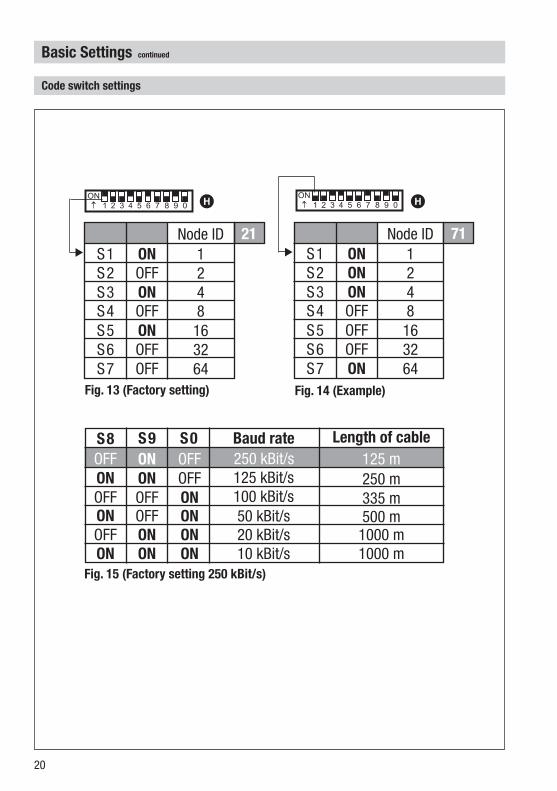
Codeswitchsettings
Fig.13(Factorysetting) Fig.14(Example)
Fig.15(Factorysetting250kBit/s)
ONNode ID
S ONS2 2ONS3 4OFFS4 8OFFS5 6OFFS6 32ONS7 64
ONNode ID
S OFFS2 2ONS3 4OFFS4 8ONS5 6OFFS6 32OFFS7 64
21 71
BaudrateS8 S9 S0250 kBit/s
Lengthofcable25 mOFFONOFF
OFF 25 kBit/sONON 250 mON 00 kBit/sOFFOFF 335 mON 50 kBit/sOFFON 500 mON 20 kBit/sONOFF 000 mON 0 kBit/sONON 000 m
H H
2
BasicSettingscontinued
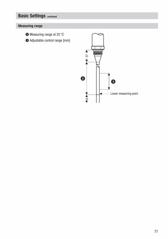
Measuringrange
Lower measuring point
1
2 Measuring range at 25 °C
3 Adjustable control range [mm]
3726
2 3

22
Turn on power for level switch NRS 2-40 / level controller NRR 2-40.
Commissioning
Check whether the level electrode NRG 26-40 and the corresponding system components NRS 2-40 / NRR 2-40 have been wired according to wiring diagram Fig.11.
Checkwiring
Applymainsvoltage
Operation
Operation in conjunction with switching controller NRS 2-40 in (pressurised) hot water installations and steam plants to TRD 40, TRD 602, TRD 604, EN 2952, EN 2953 or according to national regulations.
LevelelectrodewithCANbus
Note
To analyse and eliminate malfunctions refer to “Fault finding list for troubleshooting” on pages 23 - 24.
If the liquid level changes considerably over a short period of time during operation, the attenuation setting of the level signal should be modified. The default attenuation value set at our works is 9 seconds. . Undo screws E and remove housing cover G.2. Write down the node ID and the baud rate. Pull out the CAN bus connector.2. Set code switch S to ON, S 2 – S 7 to OFF.
S S 2 S 3 S 4 S 5 S 6 S 7ON OFF OFF OFF OFF OFF OFF
3. Use code switches S 8 – S 0 to set the attenuation value.
S 8 S 9 S 0 Attenuation [s]OFF OFF OFF 3ON OFF OFF 5OFF ON OFF 7ON ON OFF 9OFF OFF ON 5ON OFF ON 9OFF ON ON 25ON ON ON 29
Adjustingtheattenuationofthelevelcontroller

23
Malfunctions
Faultfindinglistfortroubleshooting
Fault: LED “Power” does not light up.Remedy: Apply mains voltage. Wire equipment according to the wiring diagram.
Fault: The electrode housing does not have earth connection to the boiler.Remedy: Clean seating surfaces and insert metal joint ring (of stainless steel .430)
D 33 x 39 to DIN 7603. Do not insulate level electrode with hemp or PTFE tape.
Fault: The thermal fuse has been triggered.Remedy: The ambient temperature must not exceed 70 °C.
Fault: The LED I does not light up. No data exchange.Remedy: Check level switch/controller. Connect electrode according to the wiring diagram.
Theequipmentfailstowork–nofunction
Fault: In spite of correct wiring and commissioning of the equipment an interference signal is indicated.
Remedy: The interference signal is caused by H. F. interferences coming from the installation. For interference suppression of the voltage supply we supply ferrite rings, stock code 47253. The 230 V supply lines should be looped through the ferrite ring five to ten times. If several controllers are used in the system, they can be fed from the interference suppressed supply lines. For the interference suppression of the bus line we supply hinged-shell ferrite rings, stock code 47254. The hinged-shell ferrite rings are clamped onto the bus line close to the terminal strip of the controller.
Operationcontinued
Adjustingtheattenuationofthelevelcontrollercontinued
4. Re-insert the CAN bus connector. Green LED illuminated: The new attenuation setting has been accepted.
Red LED 2 illuminated: The new attenuation setting has not been accepted. Repeat the adjustment procedure or replace the electronic insert.
5. Pull out the CAN bus connector. Set the original node ID and baud rate. Re-insert the CAN bus connector. The level electrode will now use the new attenuation setting.
6. Replace housing cover G and use screws E to fix it.

24
Fault: The electrode has been installed without protection tube. The protection tube serves as reference electrode.
Remedy: Install protection tube.
Fault: The desired zero point is not within the measuring range of the electrode. The electrode is too short.
Remedy: Replace level electrode. Choose adequate electrode length.
Fault: Dirt deposits have accumulated on the electrode rod. Remedy: Remove level electrode and clean electrode rod with a wet cloth.
Fault: The internal seal of the electrode rod is damaged.Remedy: Replace level electrode.
Fault: The vent hole in the protection tube does not exist, is obstructed of flooded.Remedy: Check protection tube and, if necessary, provide vent hole.
Theequipmentdoesnotworkaccurately
Fault: The level electrode responds too slowly to changes in the liquid level.Remedy: Rectify the attenuation setting.
Fault: The isolating valves of the external measuring pot (optional) are closed.Remedy: Open isolating valves.
Malfunctionscontinued
Faultfindinglistfortroubleshootingcontinued
If faults occur that are not listed above or cannot be corrected, please contact our service centre or authorized agency in your country.If faults occur that are not listed above or cannot be corrected, please contact our service centre or authorized agency in your country.

25
Declarationofconformity
Annex
We hereby declare that the equipment NRG26-40 conforms to the following European guidelines: LV guideline 73/23/eec version 93/68/eec EMC guideline 89/336/eec version 93/68/eec ATEX Directive 94/9/EC of 23 March 994This declaration is no longer valid if modifications are made to the equipment withoutconsultation with us.
Bremen, 3rd January 2005GESTRA AG
Dipl.-Ing. Lars Bohl(Academically qualified engineer)
Quality Assurance Manager
Dipl.-Ing. Uwe Bledschun(Academically qualified engineer)
Head of the Design Dept.
Decommissioning
Danger
Risk of severe burns and scalds to the whole body!Before removing the level electrode make sure that the vessel and the measuring pot are depressurised (O bar) and cooled down to room temperature (20 °C).
Remove the level electrode and separate the waste materials, using the material specifications as a reference. Electronic components (circuit boards) must be disposed of properly.For the disposal of the level electrode observe the pertinent legal regulations concerning waste disposal.
Disposal

26
Foryournotes

27
Foryournotes

2880274-02/206cm · © 998 GESTRA AG · Bremen · Printed in Germany
GreatBritain
FlowserveFlowControl(UK)Ltd.Burrel Road, Haywards HeathWest Sussex RH 6 TLTel. 00 44 4 44 / 3 44 00Fax 00 44 4 44 / 3 45 57E-mail: [email protected]
Italia
FlowserveS.p.A.Flow Control DivisionVia Prealpi, 30l-20032 Cormano (MI)Tel. 00 39 02 / 66 32 5Fax 00 39 02 / 66 32 55 60E-mail: [email protected]
GESTRAESPAÑOLAS.A.Luis Cabrera, 86-88E-28002 MadridTel. 00 34 9 / 5 5 20 32Fax 00 34 9 / 4 3 67 47; 5 5 20 36E-mail: [email protected]
España
FlowserveGESTRAU.S.234 Ampere DriveLouisville, KY 40299Tel.: 00 5 02 / 502 267 2205Fax: 00 5 02 / 502 266 5397E-mail: [email protected]
USA
Portugal
FlowservePortuguesa,Lda.Av. Dr. Antunes Guimarães, 59Porto 400-082Tel. 0 03 5 22 / 6 9 87 70Fax 0 03 5 22 / 6 0 75 75E-mail: [email protected]
Polska
GESTRAPOLONIASpolkaz.o.o.Ul. Schuberta 04PL - 80-72 GdanskTel. 00 48 58 / 3 06 0 -02 od 0Fax 00 48 58 / 3 06 33 00E-mail: [email protected]
Agencies all over the world:
www.gestra.de
GESTRAAGP. O. Box 0 54 60, D-28054 Bremen Münchener Str. 77, D-2825 BremenTelephone +49 (0) 42 35 03 - 0 Fax +49 (0) 42 35 03 - 393E-Mail [email protected] Internet www.gestra.de
GESTRA