Gestion de Mobilité Supportée par le Réseau dans les ...
173
HAL Id: pastel-00005406 https://pastel.archives-ouvertes.fr/pastel-00005406 Submitted on 4 Sep 2009 HAL is a multi-disciplinary open access archive for the deposit and dissemination of sci- entific research documents, whether they are pub- lished or not. The documents may come from teaching and research institutions in France or abroad, or from public or private research centers. L’archive ouverte pluridisciplinaire HAL, est destinée au dépôt et à la diffusion de documents scientifiques de niveau recherche, publiés ou non, émanant des établissements d’enseignement et de recherche français ou étrangers, des laboratoires publics ou privés. Gestion de Mobilité Supportée par le Réseau dans les Réseaux Sans Fil Hétérogènes Huu-Nghia Nguyen To cite this version: Huu-Nghia Nguyen. Gestion de Mobilité Supportée par le Réseau dans les Réseaux Sans Fil Hétérogènes. domain_other. Télécom ParisTech, 2009. Français. pastel-00005406
Transcript of Gestion de Mobilité Supportée par le Réseau dans les ...

HAL Id: pastel-00005406https://pastel.archives-ouvertes.fr/pastel-00005406
Submitted on 4 Sep 2009
HAL is a multi-disciplinary open accessarchive for the deposit and dissemination of sci-entific research documents, whether they are pub-lished or not. The documents may come fromteaching and research institutions in France orabroad, or from public or private research centers.
L’archive ouverte pluridisciplinaire HAL, estdestinée au dépôt et à la diffusion de documentsscientifiques de niveau recherche, publiés ou non,émanant des établissements d’enseignement et derecherche français ou étrangers, des laboratoirespublics ou privés.
Gestion de Mobilité Supportée par le Réseau dans lesRéseaux Sans Fil Hétérogènes
Huu-Nghia Nguyen
To cite this version:Huu-Nghia Nguyen. Gestion de Mobilité Supportée par le Réseau dans les Réseaux Sans FilHétérogènes. domain_other. Télécom ParisTech, 2009. Français. �pastel-00005406�

Thèse Présentée pour Obtenir le Grade de Docteur
de TELECOM ParisTech
Spécialité: Informatique et Réseaux
Nguyen Huu Nghia
Gestion de Mobilité Supportée par le Réseau
dans les Réseaux Sans Fil Hétérogènes
Thèse prévue le 7 juillet 2009, devant le jury composé de :
Rapporteurs Prof. Thomas Noël, LSIIT, Université Louis Pasteur
Prof. Andrzej Duda, Grenoble INP ENSIMAG
Examinateurs Maitre de Conférence HDR Houda Labiod, Telecom ParisTech
Maitre de Conférence Laurent Toutain, Telecom Bretagne
Directeur de thèse Prof. Christian Bonnet, Eurecom


Thesis In Partial Fulfillment of the Requirements
for the Degree of Doctor of Philosophy from TELECOM ParisTech
Specialization: Computer Science and Networking
Nguyen Huu Nghia
Network-based Mobility Management
in Heterogeneous Wireless Networks
Defense scheduled on July 7th 2009, before a jury composed of:
Reporters Prof. Thomas Noël, LSIIT, Université Louis Pasteur
Prof. Andrzej Duda, Grenoble INP ENSIMAG
Examiners Associate Prof. Houda Labiod, Telecom ParisTech
Associate Prof. Laurent Toutain, Telecom Bretagne
Thesis supervisor Prof. Christian Bonnet, Eurecom


- i -
ACKNOWLEDGMENTS
First and foremost, I would like to express my heartfelt gratitude to my adviser Professor Christian Bonnet for his brilliant supervision and encouragement over the past years of my PhD. I would like to thank for the freedom and the wise guidance he has offered me within my research. Without his technical insight and sharp advices, it would have been impossible to complete this thesis in line with future research perspectives, and to present my results in several international conferences. It has been my real pleasure to work with Christian.
I would like to acknowledge Hirokazu Naoe (SHARP Corporation) who helped me so much with his stimulating technical discussions and constructive publication reviewing. A special warm thank to my master advisor Michelle Wetterwald for her kindness and words of wisdom which facilitate not only my research but also my life.
In addition, many thanks go to my jury members: Prof. Thomas Noël, Prof. Andrzej Duda, Associate Prof. Houda Labiod, and Associate Prof. Laurent Toutain for their time and insights into this study.
My work with Christian Bonnet, Lamia Romdhani, Giuliana Iapichino and Eurecom Platform team gave me the chance to gain a valuable experience. I’m very grateful to Dr. Navid Nikaein for helping me to improve this thesis. I also want to thank all the staff in the Mobile Communication Department and Eurecom for their warm reception and for the financial support of my work.
I would like to express my appreciation to my colleagues and friends at Eurecom. Special thanks go to my dearest friends, Antony Schutz, Fadi Abi Abdallah, Jinhui Chen, for all the unforgettable enjoyable moments and their helps. I also wish to extend my warmest thanks to all my friends in Nice, in France, in Vietnam for all the wonderful time we spend together. My best memories for you will never die.
Finally I wish to express my love and my deepest gratitude to my family for their wholehearted support. I thank to my loving mother and sister for their continuous encouragement and enduring belief that I can do anything I set my mind to. Thanks extend to my father who has been also my savvy mentor, my trusted friend. I am greatly indebted to my wife, Thu Thuy. I am deeply grateful to her for enriching my life with many wonderful gifts, and above all, my little son Tung Lam.

- ii -

- iii -
ABSTRACT
Providing mobility support in the Internet has been a long-standing challenge with a variety of host-based mobility management solutions, such as MIPv4, MIPv6, mSCTP, and HIP. However, the host stack change requirement has created difficulties for the adoption of host-based mobility management. As a consequence, Proxy Mobile IPv6 is introduced as a network-based mobility management solution to minimize host stack software complexity, and optimize handover performance. It is seen as the protocol for achieving a common mobile core network, accommodating different access technologies such as IEEE WLAN, WiMAX, 3GPP and 3GPP2 radio networks.
In this dissertation, we focus on challenges to support Proxy Mobile IPv6 in heterogeneous wireless networks, of which the topology can be statically defined but more likely to be arbitrary and organized as spontaneous wireless mesh networks.
We propose the cluster-based architecture to scale up the network, that is, the network is divided into clusters and gradually increased by adding new clusters. Subsequently, we propose an extension to PMIPv6 for scalability support in large wireless networks in a cluster-based manner. We have evaluated the scalability of our framework, called Scalable Proxy Mobile IPv6 (SPMIPv6), in a wireless mesh network context. A mathematical model has been used to investigate the scalability of the framework with consideration of the wireless mesh network size, mobile node density, and average mobile speed. Furthermore, we introduce route optimization support into the SPMIPv6 framework, and then propose an enhanced IP-Layer network-based movement detection mechanism to deal with an environment employing heterogeneous radio access technologies. We implement the framework under Linux and summarize our practices in a virtualization-based process. We setup both virtual and real wireless mesh testbeds and run each in different scenarios to evaluate important information, such as signaling cost, handover latency, packets loss, Round Trip Time (RTT), and TCP throughput.
Finally, we consider PMIPv6 in an Always Best Connected vision, which considers multi-interface mobile nodes and multiple simultaneous access technologies in fully overlapped coverage areas to enable the best use of network resources. We provide a virtual Stream Control Transmission Protocol (vSCTP) tunneling method to overcome the limitation of IP tunneling and implement a proof-of-concept for validating the simultaneous access scenario under Network Simulator 2 (Ns-2). The simulation results show that the vSCTP tunneling method is beneficial for both users and operators. From the user perspective, the bandwidth is improved with wireless bandwidth aggregation. From the operator perspective, the load balancing performance can be improved by switching flows or packets to the right radio interface.

- iv -

- v -
ABSTRAIT
Proxy Mobile IPv6 (PMIPv6) est présenté comme une solution de gestion de mobilité supportée par le réseau pour minimiser la complexité de la pile protocolaire des terminaux mobiles, et pour optimiser la performance du handover. PMIPv6 est vu comme un protocole de gestion de mobilité dans un réseau cœur mobile commun à différentes technologies d'accès telles que : IEEE 802.11, WiMax, 3GPP, et 3GPP2.
Dans cette thèse, nous nous intéressons à la mise en œuvre de PMIPv6 dans les réseaux sans fil hétérogènes, dont la topologie ne peut pas être forcément statiquement définie mais plutôt être arbitraire et spontanée, organisée en tant que réseaux maillés sans fil. Nous proposons d'abord le concept de groupe autonome ou «cluster» qui permet le passage à l’échelle des réseaux par l’ajout de nouveaux clusters. Ensuite nous proposons des extensions à PMIPv6 qui prennent en compte l’architecture en clusters au travers de l’interaction entre de multiples LMAs (i.e. des points de gestion locale des équipements mobile) pour supporter des réseaux sans fil à grand échelle. Nous évaluons l’aptitude à supporter le passage à l’échelle de notre extension, appelée Scalable Proxy Mobile IPv6 (SPMIPv6), dans un contexte de réseau maillé sans fil en faisant varier sa taille, la vitesse moyenne et la densité des terminaux mobiles. En outre, nous proposons des méthodes pour l’optimisation du routage dans SPMIPv6 pour réduire les latences des communications. Nous introduisons également un mécanisme de détection de mouvements des terminaux mobiles qui prend en compte de l’hétérogénéité des technologies d’accès. Afin de tester les performances de ces extensions, nous implémentons l’ensemble des propositions dans un environnement virtualisé. Nous expérimentons différents scénarios dans le mode émulation ainsi qu’en vrai grandeur pour évaluer des mesures différentes telle que le coût de signalisation, la latence de handover, la perte de paquets, le temps aller-retour (RTT), et variation de débit.
Finalement, nous adressons le contexte de multi-domiciliation (multi-homing) en proposant un concept appelé virtual Stream Control Transmission Protocol (vSCTP) et l’appliquons à l’architecture PMIPv6. Les premières simulations sous Ns-2 laissent entrevoir des bénéfices pour les scénarios d’agrégation de bande passante et les scénarios d'équilibrage de charge.

- vi -

- vii -
TABLE OF CONTENTS Acknowledgments....................................................................................................... i Abstract .................................................................................................................... iii Abstrait ....................................................................................................................... v Table of Contents ..................................................................................................... vii Table of Figures .........................................................................................................xi Abbreviations.......................................................................................................... xiii Résumé ....................................................................................................................... 1 1. Introduction ........................................................................................................ 1 2. SPMIPv6 pour le passage à l’échelle. .................................................................. 2
3. Optimisation de Route (RO) dans SPMIPv6 ........................................................ 7
4. Détection de mouvements basée sur réseau dans les environnements hétérogènes9
5. Implémentation de SPMIPv6 avec RO .............................................................. 11
6. Évaluation de SPMIPv6 avec RO ...................................................................... 16
7. VSCTP Tunneling for Multi-homing Support in PMIPv6 .................................. 18
8. Applications du SPMIPv6 avec RO .................................................................. 20
9. Conclusions et Perspectives .............................................................................. 20 Chapter 1 - Introduction ............................................................................................ 25 1. Motivation ........................................................................................................ 25 2. Problem Statement ............................................................................................ 26 3. Outline of the Dissertation ................................................................................ 27 Chapter 2 - Mobility Management Protocols ............................................................. 29
1. Overview of Mobility Management .................................................................. 29
1.1. Problem Statement ................................................................................... 29
1.2. Taxonomy ................................................................................................ 30 1.2.1. Protocol Layer...................................................................................... 30
1.2.2. Addressing Scheme .............................................................................. 31
1.2.3. Routing Scheme ................................................................................... 31
1.2.4. Architectural Impact ............................................................................. 32
1.2.5. Mobility Management Scope ................................................................ 33
1.3. Multi-homing Consideration ..................................................................... 34
1.3.1. Concepts and Taxonomy ...................................................................... 34
1.3.2. Multi-homing benefits .......................................................................... 35
1.3.3. Multi-homing versus Mobility .............................................................. 37
2. IETF Mobility Management Protocols .............................................................. 38
2.1. Mobile IPv6 ............................................................................................. 38 2.1.1. Overview ............................................................................................. 38
2.1.2. Protocol Descriptions ........................................................................... 38
2.1.3. Shortcomings ....................................................................................... 39
2.2. Host Identity Protocol............................................................................... 39
2.2.1. Overview ............................................................................................. 39

- viii -
2.2.2. Protocol Descriptions ........................................................................... 40
2.2.3. Shortcomings ....................................................................................... 41
2.3. Mobile Stream Control Transmission Protocol .......................................... 42
2.3.1. Overview ............................................................................................. 42
2.3.2. Protocol Descriptions ........................................................................... 43
2.3.3. Shortcomings ....................................................................................... 45
2.4. Network-based Localized Mobility Management ...................................... 46
2.4.1. Overview ............................................................................................. 46
2.4.2. Architecture ......................................................................................... 46
2.4.3. MN-MAG Interface ............................................................................. 48
2.4.4. MAG-LMA Interface (PMIPv6) ........................................................... 48
2.4.5. Shortcomings ....................................................................................... 49
3. Conclusions ...................................................................................................... 50 Chapter 3 - Scalable Proxy Mobile IPv6 .................................................................... 51 1. Problem Overview ............................................................................................ 51 2. Hierarchical Mobility Management Architecture ............................................... 52
3. Cluster-based Mobility Management Architecture ............................................. 54
4. Scalable Proxy Mobile IPv6 Extension ............................................................. 56
4.1. General .................................................................................................... 56 4.2. Detecting Communication Establishment ................................................. 58
4.3. Locating the Serving Entities .................................................................... 58
4.4. Maintaining Routing Information ............................................................. 58
4.5. Message Structure .................................................................................... 59
4.6. Intra-cluster Communication Scenario ...................................................... 60
4.7. Intra-cluster Mobility Scenario ................................................................. 61
4.8. Inter-cluster Communication Scenario ...................................................... 62
4.9. Inter-cluster Mobility Scenario ................................................................. 62
5. Numerical Analysis of SPMIPv6 in WMN ........................................................ 63
5.1. Assumptions............................................................................................. 63
5.2. Cell dwell time ......................................................................................... 64 5.3. Per-cell Handover Rate ............................................................................. 64
5.4. Handover failure probability ..................................................................... 64
5.5. Numerical Results .................................................................................... 65
6. Conclusion ....................................................................................................... 67 Chapter 4 - On the Route Optimization & Movement Detection in SPMIPv6 ............. 69
1. Route Optimization Extension for SPMIPv6 ..................................................... 69
1.1. Problem Statement ................................................................................... 69
1.2. Conceptual Architecture ........................................................................... 71
1.3. RO Trigger ............................................................................................... 72 1.4. Intra-cluster RO Setup .............................................................................. 72
1.5. Inter-cluster RO Setup .............................................................................. 73
1.6. RO Maintenance ...................................................................................... 74
1.7. Message Structure .................................................................................... 75
2. Movement Detection for Heterogeneity ............................................................ 76
2.1. Problem Statement ................................................................................... 76
2.2. Enhanced IP-Layer Movement Detection .................................................. 77
2.2.1. Assumptions ........................................................................................ 77
2.2.2. Algorithm Descriptions ........................................................................ 78
3. Applications of SPMIPv6 with RO Support ...................................................... 80

- ix -
4. Conclusion ....................................................................................................... 83 Chapter 5 - Implementation and Evaluation ............................................................... 85 1. Implementation ................................................................................................. 85 2. Virtualization-based Development Process ....................................................... 86
3. Virtual Wireless Networking Environment ........................................................ 89
4. Qualitative Evaluation ...................................................................................... 90 4.1. Intra-cluster Scenarios .............................................................................. 90
4.1.1. Virtual IPv6 Wireless Mesh Network Topology ................................... 90
4.1.2. Scenario 1: Location Registration ......................................................... 91
4.1.3. Scenario 2: Intra-cluster Communication .............................................. 92
4.1.4. Scenario 3: Intra-cluster Mobility ......................................................... 94
4.2. Inter-cluster Scenarios .............................................................................. 94
4.2.1. Virtual IPv6 Wireless Mesh Network Topology ................................... 94
4.2.2. Scenario 1: Inter-cluster Communication .............................................. 95
4.2.3. Scenario 2: Inter-cluster Mobility ......................................................... 96
5. Quantitative Evaluation .................................................................................... 97 5.1. Virtual IPv6 Wireless Mesh Network Topology ........................................ 97
5.2. Signaling Cost in Terms of Delay ............................................................. 98
5.2.1. Intra-clusters Communication. .............................................................. 98
5.2.2. Inter-clusters Communication. .............................................................. 99
5.3. Handover Latency .................................................................................. 100
5.4. Impact of RO on Round Trip Time ......................................................... 102
5.5. Impact of RO on TCP Throughput .......................................................... 103
6. Conclusion ..................................................................................................... 105 Chapter 6 - Multi-homing for wireless bandwidth aggregation and load-balancing in PMIPv6 .................................................................................................................. 107 1. Problem Overview .......................................................................................... 107 2. Multiple Care-of Addresses Registration & Flow Binding ............................... 108
3. Virtual SCTP Tunneling Framework ............................................................... 109
3.1. Conceptual Architecture ......................................................................... 110
3.2. Encapsulating Packet Structure and Packet Bundling .............................. 110
3.3. Predictive Packet Bundling ..................................................................... 111
3.4. Per-packet Dynamic Forwarding ............................................................ 112
3.5. Simplification of Tunnel Management .................................................... 112
4. Evaluation ...................................................................................................... 112 4.1. Encapsulation Overhead Consideration ................................................... 112
4.2. Delay Consideration ............................................................................... 113
4.3. Evaluation of vSCTP tunneling in PMIPv6 ............................................. 114
4.4. Evaluation of vSCTP tunneling in NEMO .............................................. 118
5. Conclusion ..................................................................................................... 123 Chapter 7 - Conclusions and Outlook ...................................................................... 125 1. Conclusion ..................................................................................................... 125 2. Limitation of the work .................................................................................... 128 3. Perspectives .................................................................................................... 128 Appendix A - SPMIPv6 Design Detail .................................................................... 131 1. Convention ..................................................................................................... 131 2. Message Format ............................................................................................. 131

- x -
2.1. Proxy Binding Update Message .............................................................. 132
2.2. Proxy Binding Acknowledgement Message ............................................ 134
2.3. Proxy Binding Request Message ............................................................ 135
2.4. Proxy Binding Response Message .......................................................... 136
3. Mobility Otions .............................................................................................. 137 3.1. Mobile Node Identifier Option............................................................... 137
3.2. Home Network Prefix Option ................................................................. 138
3.3. Mobile Node Interface Identifier Option ................................................. 138
3.4. Timestamp Option .................................................................................. 139
3.5. Link-local Address Option...................................................................... 139
3.6. Serving Entity Address or Source MN Address Options ......................... 140
Appendix B - Virtualization Technologies ............................................................... 143 1. Full Virtualization .......................................................................................... 143 2. Paravirtualization ............................................................................................ 144 3. Operating System-level Virtualization ............................................................ 145
Publications ............................................................................................................ 147 Bibliography ........................................................................................................... 149

- xi -
TABLE OF FIGURES Figure 1. Mobility Management Classification by Protocol Layer ............................. 30
Figure 2. Mobility Management Classification by Addressing Scheme ....................... 31 Figure 3. Mobility Management Classification by Routing Scheme ............................ 32
Figure 4. Mobility Management Classification by Architectural Impact..................... 32 Figure 5. Mobility Management Classification by Scope ........................................... 33
Figure 6. A typical multi-homing scenario ................................................................. 35 Figure 7. Multi-homing and Mobility protocol portfolios ........................................... 37
Figure 8. The difference between the bindings of the logical entities .......................... 39 Figure 9. The HIP packet structure ........................................................................... 40 Figure 10. HIP Base Exchange ................................................................................. 41
Figure 11. A schematic view of an SCTP association ................................................. 43
Figure 12. SCTP association setup message sequence ............................................... 44
Figure 13. A mSCTP handover scenario .................................................................... 45 Figure 14. Protocol stack for NetLMM solution ........................................................ 47 Figure 15. Proxy Mobile IPv6 Sequence Diagram ..................................................... 49 Figure 16. Hierarchical Mobility Management with GMM and LMM ........................ 53 Figure 17. Scalability with Cluster-based Architecture .............................................. 54
Figure 18. SPMIPv6 seen in a peer-to-peer overlay network ..................................... 56
Figure 19. Attachment process in SPMIPv6 with per-MN prefix ................................ 57
Figure 20. Proxy Binding Request (PBReq) Message ................................................ 59
Figure 21. Proxy Binding Response (PBRes) Message............................................... 59
Figure 22. Serving Entity or Source MN Address Options ......................................... 59
Figure 23. Intra-cluster Communication Establishment ............................................. 60
Figure 24. Intra-cluster Mobility ............................................................................... 61
Figure 25. Inter-clusters communication establishment ............................................. 62
Figure 26. Structure of a cluster ................................................................................ 63
Figure 27. Successful per-cell handover probability .................................................. 66
Figure 28. Successful per-cell handover rate ............................................................. 66 Figure 29. Route Optimization Support for SPMIPv6 ................................................ 71
Figure 30. Route Optimization Setup ......................................................................... 73 Figure 31. Inter-cluster Route Optimization Setup ..................................................... 74 Figure 32. Proxy Binding Request Message............................................................... 75 Figure 33. Proxy Binding Response Message ............................................................ 75 Figure 34. Example of Enhanced Network-based IP-Layer Movement Detection ....... 80 Figure 35. Extended PMIPv6 for post-disaster network deployment .......................... 82 Figure 36. Extended PMIPv6 for coverage extension of fixed infrastructure .............. 83 Figure 37. PMIPv6 Software Architecture ................................................................. 86 Figure 38. Virtualization with User-mode Linux ........................................................ 87 Figure 39. Unified Development Process for Mobile IP in UML/real testbed ............. 88 Figure 40. User-mode Linux and Ns-2 Emulation ...................................................... 89 Figure 41. Virtual Testbed for Intra-cluster Communication ..................................... 90
Figure 42. Virtual Testbed for Inter-cluster Communication ..................................... 95
Figure 43. Virtual Wireless Mesh Network ................................................................ 97 Figure 44. Signaling cost in terms of delay in intra-cluster communication ............... 99
- xii -
Figure 45. Signaling cost in terms of delay in inter-cluster communication................ 99 Figure 46. UDP session log during intra-cluster mobility ........................................ 100
Figure 47. Time-Sequence graph of TCP session with intra-cluster mobility ............ 101 Figure 48. CDF of RTT without/with RO in intra/inter cluster communication ....... 103 Figure 49. TCP Throughput without/with RO in intra-cluster communication ........ 104 Figure 50. A bi-directional virtual SCTP tunnel ...................................................... 110 Figure 51. An encapsulating datagram .................................................................... 111 Figure 52. The encapsulation overhead comparison (in percent of total bandwidth) 113 Figure 53: Virtual SCTP endpoint and virtual SCTP association concepts ............. 114 Figure 54: Mappings between different spaces ....................................................... 115 Figure 55. Normalized tunneling goodput vs. number of flows ................................. 116
Figure 56. Tunneling delay vs. number of flows ....................................................... 116 Figure 57. Aggregated bandwidth with virtual SCTP tunneling ............................... 117
Figure 58. A bi-directional virtual SCTP tunnel in NEMO....................................... 119
Figure 59. Simulation topology ............................................................................... 120
Figure 60. Simulation results for the second traffic class ......................................... 121
Figure 61. Simulation results for the second traffic class ......................................... 122
Figure 62. Mobility Header ..................................................................................... 131
Figure 63. Proxy Binding Update Message ............................................................. 133 Figure 64. Proxy Binding Acknowledgement Message ............................................. 134
Figure 65. Proxy Binding Request Message............................................................. 136 Figure 66. Proxy Binding Response Message .......................................................... 136 Figure 67. Mobile Node Identifier Option................................................................ 137 Figure 68. Home Network Prefix option .................................................................. 138 Figure 69. Mobile Node Interface Identifier option .................................................. 139 Figure 70. Timestamp option ................................................................................... 139
Figure 71. Link-local Address option ...................................................................... 140 Figure 72. Serving Entity or Source MN Address Options ....................................... 140
Figure 73. Full virtualization uses a hypervisor to share the underlying hardware .. 143 Figure 74. Paravirtualization integrates code into the guest operation system ......... 144 Figure 75. Operating system-level virtualization isolates servers ............................. 145

- xiii -
ABBREVIATIONS Readers can find here the abbreviations and acronyms used throughout the thesis. The meaning of an acronym is usually indicated once, when it first occurs in the text. In some case, it can be repeated to facilitate the readers.
3GPP 3rd Generation Partnership Project
ABC Always Best Connected
ADDIP Dynamic Address Reconfiguration for Stream Control Transmission Protocol
API Application Programming Interface
AR Access Router
BC Binding Cache
BGP Border Gateway Protocol
CN Correspondent Node
CoA Care of Address
CPU Central Processing Unit
DAD Duplicate Address Detection
DHCP Dynamic Host Configuration Protocol
DHCPv6 Dynamic Host Configuration Protocol for IPv6
DNA Detecting Network Attachment
DNAv6 Detecting Network Attachment in IPv6
DNS Domain Name System
DoS Denial of Service

- xiv -
DSL Digital Subscriber Line
ESP Encapsulating Security Payload
FA Foreign Agent
FQDN Full Qualified Domain Name
GMM Global Mobility Management
GRE Generic Routing Encapsulation
HA Home Agent
HI Host Identity
HIP Host Identity Protocol
HIT Host Identity Tag
HMIPv6 Hierarchical Mobile IPv6
HoA Home Address
ICMPv6 Internet Control Message Protocol Version 6
IEEE Institute of Electrical and Electronics Engineers
IETF Internet Engineering Task Force
IGP Interior Gateway Protocol
IP Internet Protocol
IPSec Internet Protocol Security
IPv4 Internet Protocol version 4
IPv6 Internet Protocol version 6
ISP Internet Service Provider
LMA Localized Mobility Anchor
LMD Localized Mobility Domain

- xv -
LMM Localized Mobility Management
MAC Medium Access Control
MAG Mobile Access Gateway
MIPL Mobile IP for Linux
MIPv4 Mobile IPv4
MIPv6 Mobile IPv6
MN Mobile Node
MNID Mobile node identifier
MOBIKE IKEv2 Mobility and Multihoming
MONAMI6 Mobile Nodes and Multiple Interfaces in IPv6
MPLS Multiprotocol Label Switching
mSCTP mobile Stream Control Transmission Protocol
MTU Maximum Transmission Unit
MULTI6 Site Multihoming in IPv6
NA Neighbor Advertisement
NDP Neighbor Discovery Protocol
NDPv6 Neighbor Discovery for IP Version 6
NetLMM Network-based Localized Mobility Management
NS Neighbor Solicitation
Ns-2 Network Simulator 2
NUD Neighbor Unreachability Detection
PDA Personal Digital Assistant
PMIPv6 Proxy Mobile IPv6

- xvi -
QoS Quality of Service
RA Router Advertisement
RFC Request For Comments
RO Route Optimization
RS Router Solicitation
RVS Rendezvous Server
SA Security Association
SCTP Stream Control Transmission Protocol
SEND Secure Neighbor Discovery
SHIM6 Site Multihoming by IPv6 Intermediation
SPI Security Parameter Index
SPMIPv6 Scalable Proxy Mobile IPv6
TCP Transmission Control Protocol
UML User-mode Linux
UMTS Universal Mobile Telecommunications System
VPN Virtual Private Network
vSCTP virtual Stream Control Transmission Protocol
WiMAX Worldwide Interoperability for Microwave Access
WLAN Wireless Local Area Network
WMN Wireless Mesh Network

- 1 -
RESUME
1. Introduction
Nous adressons la mobilité comme l'action de changement du point d'attachement dans un réseau d'accès sans fil tout en gardant la continuité des sessions. L'objectif principal de la gestion de mobilité est de réduire au minimum la rupture de service due à la perte de données et au délai de handover. Comment fournir l'appui de mobilité dans l'Internet est un défi depuis longtemps. En conséquence, de différentes solutions de gestion de mobilité ont été conçues : comme Mobile IPv4 et Mobile IPv6 à la couche 3, mobile Stream Control Transmission Protocol (mSCTP) à la couche 4, et Host Identity Protocol (HIP) à la couche 3,5. Cependant, malgré tous ces efforts, le service de mobilité « n'importe quand n'importe où » sur l'Internet n'est pas encore une réalité. Il y a beaucoup de raisons pour cela, telles que le coût technique de déploiement des solutions de gestion de mobilité proposées. En particulier, ce sont les solutions de gestion de mobilité gérées par les hôtes mobiles ; ce qui exigent des changements de pile protocolaire non seulement du côté des appareils mobiles eux-mêmes mais également du côté de leurs nœuds correspondants. La nécessité de la participation des hôtes mobiles à la gestion de mobilité est un obstacle primaire pour l'adoption de protocole. Pour surmonter ces obstacles, un nouveau paradigme de gestion de mobilité, appelé la gestion de mobilité supportée par le réseau, est suggéré pour minimiser la complexité de pile protocolaire des hôtes mobiles, et est normalisé dans le groupe de travail Network-based Localized Mobility Management (NetLMM) de l'Internet Engineering Task Force (IETF).
Proxy Mobile IPv6 (PMIPv6) est présenté comme une solution de gestion de mobilité supportée par le réseau pour minimiser la complexité de la pile protocolaire des terminaux mobiles, et pour optimiser la performance du handover. PMIPv6 est vu comme un protocole de gestion de mobilité dans un réseau cœur mobile commun à différentes technologies d'accès telles que : IEEE 802.11, WiMax, 3GPP, et 3GPP2. Dans cette thèse, nous nous intéressons à la mise en œuvre de PMIPv6 dans les réseaux sans fil hétérogènes, dont la topologie ne peut pas être forcément statiquement définie mais plutôt être arbitraire et spontanée, organisée en tant que réseaux maillés sans fil.

- 2 -
2. SPMIPv6 pour le passage à l’échelle. Le premier défi concerne le passage à l’échelle de PMIPv6 dans de grands réseaux
sans fil hétérogènes. Le passage à l’échelle est un facteur clé de succès pour des applications dans un environnement dynamique et peut être défini comme la capacité d'un réseau d'ajouter ou maintenir sa disponibilité à mesure que la taille du réseau augmente. Le problème de passage à l’échelle se présente en considérant le nombre croissant d'utilisateurs mobiles et la limite de couverture radio. Etant donnée une densité de MN, une plus grande région géographique signifie que le réseau doivent servir plus d'utilisateurs. Ainsi, une fois que le nombre d'utilisateurs dépasse sa capacité, la performance du réseau diminue nettement. Pour une technologie d'accès, la couverture radio est limitée et exige une solution pour étendre la couverture des réseaux d'accès pour permettre aux utilisateurs mobiles d'être toujours connectés.
Schéma I. Architecture en clusters pour le passage à l’échelle
Nous proposons d'abord le concept de groupe autonome ou «cluster» qui permet le passage à l’échelle des réseaux par l’ajout de nouveaux clusters. Le schéma I montre l'architecture en clusters, dans laquelle, chaque cluster contient une tête de cluster (CH) qui a la connaissance complète au sujet de l'information d’adhésion des membres du groupe et d'état de lien dans le cluster. Les autres nœuds dans un cluster, appelé Access Routers (ARs), contrôlent des technologies d'accès radio hétérogènes et fournissent l’accès aux nœuds mobiles MNs. Tous les noeuds dans le réseau backhaul sont reliés ensemble. Aucune hypothèse sur la topologie et le protocole de cheminement n'est

faite. Nous considérons uneensemble par l'infrastructure d'Internet ou par des protocoles de chemineLe MN peut communiquer avec correspondants( CNs) mobile
Ensuite nous proposons Mobile IPv6 qui prennent enl’interaction entre de multiples LMAs (i.e. des points de gestion locale des équipements mobile) l’interaction entre de multiplesproblèmes fondamentaux suivants : (i) détection de l'établissement de communication, (ii) localisation des entités routage.
Soit MAGMN et LMAterminologie PMIP) servant et le LMAservant du MN. De même façon soit servant du CN. Pour une topologie adentre un MN et une CN par la suite MAGCN. Pour résoudre ce problème dans un environnement distribué, nous proposons un nouveau couple des messages : Binding Response (PBRes)
Nous définissons la communication dans ce travail comme entre deux nœuds. En inspectant les messages ICMPv6 ou le trafic de données, ce processus détermine lcluster ou communication d'interl'installation de chemin en cas de
- 3 -
faite. Nous considérons une topologie arbitraire entre CHs: les CHs peuensemble par l'infrastructure d'Internet ou par des protocoles de chemine
peut communiquer avec des CNs sur l'Internet, aussi bien que mobiles par l’intermédiaire de CHs et ARs.
Ensuite nous proposons une extension appelée SPMIPv6, pour Scalable Proxy qui prennent en compte l’architecture en clusters au travers de
l’interaction entre de multiples LMAs (i.e. des points de gestion locale des parce que PMIPv6 de base ne prend pas en compte de
’interaction entre de multiples LMA. Nous étendons le protocole pour résoudre les problèmes fondamentaux suivants : (i) détection de l'établissement de communication,
des entités (MR) servant du CN, et (iii) mise à jour des informations de
Schéma II. Les phases de SPMIPv6
et LMAMN respectivement le MAG (équivalent de MR dans la servant et le LMA (équivalent de CH dans la terminologie PMIP)
De même façon soit MAGCN et LMACN le MAG servant et le LMA Pour une topologie ad-hoc arbitraire, en établissant la communication
CN appartenant à différents cluster, LMAMN doit savoir LMA. Pour résoudre ce problème dans un environnement distribué, nous
proposons un nouveau couple des messages : Proxy Binding Request (PBReq) et(PBRes).
Nous définissons la communication dans ce travail comme l’ échange du trafic entre deux nœuds. En inspectant les messages ICMPv6 ou le trafic de données, ce processus détermine le cadre des communications, c.-à-d. communication d'intra
ou communication d'inter-cluster, et fournit des déclenchements pour tallation de chemin en cas de communication inter-cluster. Quand
CHs peuvent être reliés ensemble par l'infrastructure d'Internet ou par des protocoles de cheminement ad-hoc.
CNs sur l'Internet, aussi bien que des nœuds
une extension appelée SPMIPv6, pour Scalable Proxy compte l’architecture en clusters au travers de
l’interaction entre de multiples LMAs (i.e. des points de gestion locale des PMIPv6 de base ne prend pas en compte de
ocole pour résoudre les problèmes fondamentaux suivants : (i) détection de l'établissement de communication,
es informations de
MAG (équivalent de MR dans la (équivalent de CH dans la terminologie PMIP)
MAG servant et le LMA rbitraire, en établissant la communication
doit savoir LMACN, et . Pour résoudre ce problème dans un environnement distribué, nous
(PBReq) et Proxy
échange du trafic entre deux nœuds. En inspectant les messages ICMPv6 ou le trafic de données, ce
d. communication d'intra-, et fournit des déclenchements pour
Quand le réseau est

- 4 -
configuré pour le support d’un même préfixe IP partagé, les deux nœuds emploient le même préfixe de réseau. MNs dans le domaine se considèrent en tant que voisins sur le même lien et donc déclenche la procédure Neighbor Unreachability Detection (NUD) pendant leur établissement de communication. Tous les messages ICMPv6 pour la résolution d’adresse sont inspectés par les entités de bord - le MAG ou le LMA.
La localisation des entités servant du CN et l'établissement de communication est illustrée sur le schéma III. Après une série d’échange des messages PBReq et PBRes, le LMAMN peut installer une entrée de routage pour un tunnel bi-directionnel avec le LMA CN en utilisant des informations fournies dans le PBRes. En conséquence, un chemin par défaut traversant LMAs est installé pour la communication entre le MN et le CN. Le LMAMN alors répondra avec un PBRes au MAGMN. Le MAGMN exécutera le proxy ARP pour que le MN mette à jour l’entrée du CN dans son neighbor cache. Enfin, le MN peut commencer à envoyer des paquets au CN par l’intermédiaire d’une chaîne des tunnels bi-directionnels.
Schéma III. Etablissement de Communication Inter-cluster
Nous évaluons ensuite l’aptitude à supporter le passage à l’échelle de notre extension SPMIPv6 dans un contexte de réseau maillé sans fil (i. e. WMN- Wireless Mesh Network) en faisant varier sa taille, ainsi que la vitesse moyenne et la densité des terminaux mobiles. Nous considérons le WMN avec la structure cellulaire hexagonale, supposant que chaque cellule est servie par l'AR. La couverture d’un cluster est également de forme hexagonale.
- 5 -
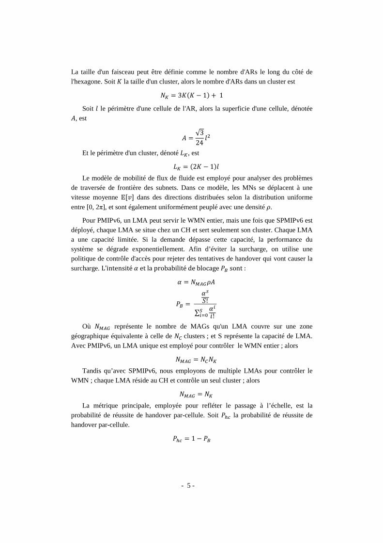
La taille d'un faisceau peut être définie comme le nombre d'ARs le long du côté de l'hexagone. Soit � la taille d'un cluster, alors le nombre d'ARs dans un cluster est
�� � 3��� � 1 1
Soit � le périmètre d'une cellule de l'AR, alors la superficie d'une cellule, dénotée
, est
�√3
24��
Et le périmètre d'un cluster, dénoté ��, est
�� � �2� � 1�
Le modèle de mobilité de flux de fluide est employé pour analyser des problèmes de traversée de frontière des subnets. Dans ce modèle, les MNs se déplacent à une vitesse moyenne ���� dans des directions distribuées selon la distribution uniforme
entre [0, 2π], et sont également uniformément peuplé avec une densité �.
Pour PMIPv6, un LMA peut servir le WMN entier, mais une fois que SPMIPv6 est déployé, chaque LMA se situe chez un CH et sert seulement son cluster. Chaque LMA a une capacité limitée. Si la demande dépasse cette capacité, la performance du système se dégrade exponentiellement. Afin d’éviter la surcharge, on utilise une politique de contrôle d'accès pour rejeter des tentatives de handover qui vont causer la
surcharge. L’intensité et la probabilité de blocage *+ sont :
� �-./�
*+ �
0
1!
∑ 4
5!6478
Où �-./ représente le nombre de MAGs qu'un LMA couvre sur une zone
géographique équivalente à celle de �9 clusters ; et S représente la capacité de LMA. Avec PMIPv6, un LMA unique est employé pour contrôler le WMN entier ; alors
�-./ � �9��
Tandis qu’avec SPMIPv6, nous employons de multiple LMAs pour contrôler le WMN ; chaque LMA réside au CH et contrôle un seul cluster ; alors
�-./ � ��
La métrique principale, employée pour refléter le passage à l’échelle, est la probabilité de réussite de handover par-cellule. Soit *:; la probabilité de réussite de handover par-cellule.
*:; � 1 � *+

- 6 -
Schéma IV. La Probabilité Réussit de Handover par-cellule
Des résultats numériques sont obtenus utilisant MATLAB® R2006b. Nous avons réalisé 500 simulations. Pour chaque simulation, nous modélisons l'augmentation de la
zone géographique du WMN en augmentant le paramètre �9. Nous modélisons la mise à niveau d'un LMA en augmentant le paramètre de k dans un intervalle de 1 à 5 parce que la capacité pourrait être illimitée en théorie mais est limitée dans la pratique. D'autres paramètres de système sont pris aléatoirement dans les intervalles ci-dessous.
Paramètre Valeurs Unit 18 250 Nodes �9 {1..20} Clusters � {2..3} � {200? .. 400?} M
���� {1..5} m/s � {0.0001 .. 0.0002} nodes/m� C {1..5}
Le schéma IV montre la probabilité de réussite de handover par-cellule dans SPMIPv6 et dans de différents cas de PMIPv6. Nous observons que, quand le réseau
est étendu horizontalement (en augmentant la valeur du paramètre �9), *:; avec
seulement un LMA diminue nettement ; tandis que *:; avec de multiple LMAs reste stable. La figure montre cinq valeurs différentes de k correspondant à cinq capacités différentes du LMA centralisé. Ceci signifie que nous pouvons étendre verticalement le
0 5 10 15 200.1
0.2
0.3
0.4
0.5
0.6
0.7
0.8
0.9
1
1.1
Network scale (NC
)
Suc
cesf
ul p
er-c
ell
han
dove
r pr
oba
bilit
y (P
hc)
k=3
SPMIPv6
k=4
k=5
k=2
k=1
PMIPv6
- 7 -
WMN en utilisant un nouveau LMA de plus grande capacité (en augmentant le paramètre de k). Cependant k est lié par une valeur limite parce que la capacité pourrait être illimitée dans la théorie mais est limité dans la pratique. Ici, nous supposons que k≤5. Notez également qu'il est toujours coûteux de remplacer un LMA centralisé par un nouveau avec une plus grande capacité. Les résultats numériques prouvent que SPMIPv6 fournit un mécanisme pour des interactions inter-LMAs qui peut horizontalement et graduellement étendre le WMN. Cette approche est moins chère que le remplacement du LMA centralisé et évite le problème du point de vulnérabilité qui est en l’occurrence l’utilisation d’un seul LMA comme proposé dans la solution PMIPv6.
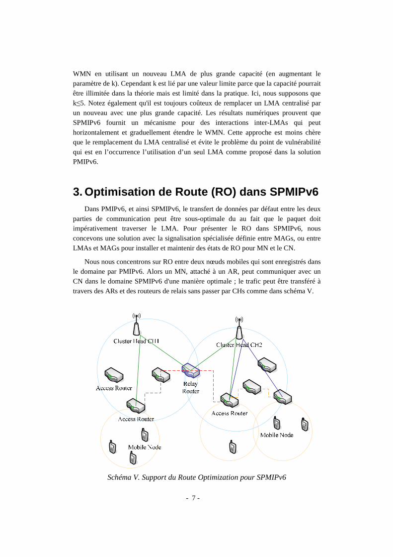
3. Optimisation de Route (RO) dans SPMIPv6 Dans PMIPv6, et ainsi SPMIPv6, le transfert de données par défaut entre les deux
parties de communication peut être sous-optimale du au fait que le paquet doit impérativement traverser le LMA. Pour présenter le RO dans SPMIPv6, nous concevons une solution avec la signalisation spécialisée définie entre MAGs, ou entre LMAs et MAGs pour installer et maintenir des états de RO pour MN et le CN.
Nous nous concentrons sur RO entre deux nœuds mobiles qui sont enregistrés dans le domaine par PMIPv6. Alors un MN, attaché à un AR, peut communiquer avec un CN dans le domaine SPMIPv6 d'une manière optimale ; le trafic peut être transféré à travers des ARs et des routeurs de relais sans passer par CHs comme dans schéma V.
Schéma V. Support du Route Optimization pour SPMIPv6

Les lignes continues montrent d'intra-cluster et de communication d'interles routes optimales pour la cluster. Nous soulignons que le déclenchement de RO devrait être mais le déclenchement de RO doit être lancé au l’échelle du domaine SPMIPv6.
Nous présentons donc une nouvelle phase «responsable d’établir les routes optimale et est décrit selon le schéma VI. supposons que le MN détecter la communication et joue le rôle du déclenchement de RO. Leau LMAMN un PBReq pour localiser les entités décision de RO auprès de LMA MN et MAGMN ont toute information nécessaire pour installer le RO. Le RO Indication (R) dans le la communication entre le
Plus tard, le MAGservant du CN, par exemple MAGl'entité servant du CN, i.e. MAGjour l'entrée de routage optimisé. Le trafic est alors MAGs, c.-à-d. MAGMN
dans la cache des MAGs et de LMAsCN dans le domaine SPMIPv6.
Schéma
- 8 -
Les lignes continues montrent la route sous-optimale en cas de communication et de communication d'inter-cluster. Les lignes en points tillés
pour la communication d'intra-cluster et la communication d'inter. Nous soulignons que le déclenchement de RO devrait être contrôlé
mais le déclenchement de RO doit être lancé au MAG pour assurerdu domaine SPMIPv6.
Nous présentons donc une nouvelle phase « Route Optimization Setupresponsable d’établir les routes optimale et est décrit selon le schéma VI.
MN lance le trafic avec le CN. Le MAGMN est responsable de détecter la communication et joue le rôle du déclenchement de RO. Le MAG
un PBReq pour localiser les entités servant du CN et pour demander la auprès de LMA MN. À la fin de la phase « Serving Entities Location
ont toute information nécessaire pour installer le RO. Le ) dans le message PBRes indique à MAGMN que RO est possible entre le MN et le CN.
Plus tard, le MAGMN envoie un PBReq avec le drapeau RO Indication , par exemple MAGCN. À la fin de cette phase RO Setup, les MAG
servant du CN, i.e. MAGCN, établissent un tunnel bi-directionnel et mettent à routage pour faire suivre le trafic à travers le tunnel bi
optimisé. Le trafic est alors transféré d'une manière optimisée directement entre
MN-MAGCN. L'état de RO de la communication est alors maintenu MAGs et de LMAs concernés pendant le déplacement
dans le domaine SPMIPv6.
Schéma VI. Les phases de SPMIPv6 avec RO
en cas de communication en points tillés montrent
unication d'inter-contrôlé par le LMA
pour assurer lé passage à
e Optimization Setup » qui est responsable d’établir les routes optimale et est décrit selon le schéma VI. Nous
est responsable de MAGMN envoie
et pour demander la Serving Entities Location »,
ont toute information nécessaire pour installer le RO. Le drapeau que RO est possible pour
Indication à l'entité , les MAGMN et
directionnel et mettent à le tunnel bi-directionnel
timisée directement entre RO de la communication est alors maintenu
déplacement de MN et de

- 9 -
Schéma VII. Etablissement du RO dans la Communication Inter-cluster
Donc pour l’optimisation de routage, deux modes sont pris en compte : l’intra et l’inter-cluster.
4. Détection de mouvements basée sur réseau dans les environnements hétérogènes Un aspect important des protocoles de gestion de mobilité est la détection de
mouvement. Cependant, cet aspect n'est pas bien considéré dans PMIPv6 même s’il y avait un grand nombre de publications au sujet de PMIPv6, et la plupart de résultats expérimentaux sont basées sur bancs de tests utilisant des câbles ou IEEE 802.11.

- 10 -
Ceci limite la vraie capacité de PMIPv6 qui est conçu pour le handover vertical entre les technologies d'accès hétérogènes, particulièrement entre 3GPP et réseaux de non-3GPP.
Comme il faudra encore beaucoup efforts pour la détection de mouvement pour chaque technologie radio d’accès. Nôtre première idée principale est de baser sur la couche IPv6 de convergence, qui sera le cœur pour les réseaux de prochaine génération, pour supporter l'hétérogénéité des appareils mobiles, des applications et des technologies radio d'accès. De notre point de vue le réseau doit être responsable de la détection de mouvement dans PMIPv6. Ceci aidera à promouvoir PMIPv6 dans la pratique graduellement et plus tard à optimiser PMIPv6 avec le mécanisme de détection de mouvement spécifique basée sur la couche 2 en longs termes. Le mécanisme proposé est indépendant de la couche 2 et accepte tous les programmes de pilotage de couche-lien existants. Toute l'intelligence est migrée au MAG pour supporter plus grand nombre d’appareils mobiles.
Dans PMIPv6 de base, le MN maintient une adresse IP qui est inchangée dans le domaine PMIPv6 et est employée pour des communications. Cette adresse est une adresse IP globale routable et est référée dans cette thèse comme l'adresse PMIPv6. Dans notre proposition, chaque MAG annonce des Router Avertissement (RAs) contenant deux préfixes : (i) un préfixe global P et (ii) un préfixe site local P*. L'adresse PMIPv6 globale est configurée à partir du préfixe global P tandis que l'adresse IP provisoire site local est configurée à partir du préfixe sitelocal P*. Chauqe fois que le MN se déplace vers un nouveau lien, il configure une nouvelle adresse provisoire et supprime l'adresse provisoire précédente. Nous voudrions souligner que cette adresse provisoire n'est pas employée pour des communications entre MN et CN. Par conséquent le délai de handover ne sera pas affecté par le délai du processus de configuration automatique de l'adresse provisoire. Le message NS dans la procédure Duplicate Address Detection (DAD) de la nouvelle adresse provisoire est employé comme le déclencheur pour la détection d'attachement de réseau.
Le schéma VIII montre un diagramme de séquence d'un scénario typique de handover, avec la détection de mouvement basée sur réseau augmentée au niveau IP, dans laquelle MN vient au domaine PMIPv6 (utilisant un préfixe partagé) et est attaché au MAG1. Comme c’est le premier attachement du MN dans le domaine PMIPv6, Toutes les deux adresses, adresse PMIPv6 et adresse temporaire, seront configurées et le message NS dans la DAD de l’adresse PMIPv6 déclenchera la procédure Location Registration. Plus tard, le MN s'éloigne de MAG1 et s'attache à MAG2. Le MN reçoit les RAs diffusés par MAG2. Cette fois, seulement l’adresse temporaire est re-configurée et donc il y a un seul message NS de la DAD pour la nouvelle adresse temporaire. Et cette fois, ce message est utilisé par MAG2 pour déclencher la procédure de détection de mouvement en envoyant un message NS pour résoudre l’adresse PMIPv6 de MN. Et dès la réception du message NA envoyé par MN comme réponse, MAG2 déclenchera la procédure Location Registration. Quant à MAG1 la

- 11 -
procédure Location Deregistration sera déclenchée soit par un timer soit par le message PBU (avec lifetime=0) envoyé par LMA.
Schéma VIII. Un scenario typique de handover avec la detection de mouvement
basée sur réseau augmentée au niveau IP
5. Implémentation de SPMIPv6 avec RO Nous avons développé SPMIPv6 avec RO tout en réutilisant Mobile IPv6 for
Linux (MIPL) version 2.0.2. Le code source de MIPL est employé comme un ensemble d'API fournissant différents services pour l'interaction entre l'espace d'utilisateur et l'espace noyau ( kernel). Tous les blocs de MIPL de base sont réutilisés d'une façon efficace.

- 12 -
NDPv6
(icmp.c)Mobility Header
(mh.c)
Task Queue
(tqueue.c)
Messages
(pmip_msgs.c)
Handler
(pmip_handlers.c)
Finite State Machine
(pmip_fsm.c)
Mobile IPv6 for Linux (MIPL v2.0)
Scalable Proxy Mobile IPv6
PMIPv6 Cache
(pmip_cache.c)
Routing Filter
(rtnl.c)
IPARSE
ISEND
ICACHE
IFSM
IHANDLER
INETLINK
Tunnel Ctl
(tunctl.c)
ITUNCTL
RO Cache
(pmip_ro_cache.c)
IROCACHE
Schéma IX. Architecture du SPMIPv6 avec RO
L’internet mobile du futur doit faire face à la gestion de mobilité et multi-domiciliation. Toutefois le travail dans tel environnement est coûteux en termes d'argent, temps et efforts; un nouveau processus de développement et d’évaluation basé sur la virtualisation devrait être considéré pour réduire ces coûts. Nous proposons une approche utilisant la technologie de virtualisation de User-mode Linux (UML) qui peut être adaptée facilement à différents buts : gestion de réseau virtuel, développement des applications distribuée ou du kernel. Le processus est alors appliqué pour développer et évaluer le cadre SPMIPv6 avec RO en respectant les contraints de version du kernel de différents projets.
Pour le fonctionnement d’une machine virtuelle UML, nous devons disposer d’un kernel UML et un système de fichiers UML. Le kernel UML est un kernel Linux compilé en mode utilisateur pour fonctionner comme une machine virtuelle dans une machine de Linux physique. Chaque machine virtuelle est munie de son propre système de fichiers virtuel. Le système de fichiers d'un UML est un système de fichier Linux standard stocké dans la machine physique sous forme d’un fichier qui peut se monter directement dans le système de fichiers physique. Ceci permet de travailler avec le système de fichiers UML sans besoin de lancer la machine virtuelle. Copie-Sur-Écrire est un autre avantage intéressant d’UML car il permet à différents machine virtuelle de fonctionner sur le même système de fichiers UML et de sauvegarder les différences dans des dossiers « .cow » séparés.

- 13 -
Schéma X. Unified Development Process for Mobile IP in UML/real testbed
Le schéma X montre le processus pratique et unifié pour le développement du Mobile IPv6 et ses extensions qui peuvent fonctionner bien dans des testbed virtuel et en vrai grandeur. A partir du code source du kernel Linux, on applique le patch UML

- 14 -
nécessaire pour ajouter une nouvelle architecture UML (ARCH=um) dans le code source du kernel Linux. Les plus récentes versions du kernel linux (à partir de la version 2.6.19) inclut déjà cette architecture. Le développement peut se faire de même façon pour l’environnement réel ou virtualisé. La seule différence c’est de choisir l’architecture correspondante pour la compilation, en mettant la valeur correspondant dans la variable ARCH. Pour le testbed réel, nous compilons le code source du kernel Linux dans l’architecture ARCH=x86/sparc/mips, etc ; tandis que pour le testbed virtuel, nous utiliserons l’architecture ARCH=um.
Pour le test de fonctionnement, nous créons des bancs de test virtualisés en utilisant la combinaison d’UML et Ns-2 Emulation. UML est utilisé pour créer de nombre de machines virtuelles et Ns-2 Emulation est utilisé pour interconnecter les machines virtuelles pour créer un environnement réseaux sans fil virtuel. Les composants de Ns-2 Emulation permettent de saisir des paquets IPv6 d’une machine virtuelle, de la faire passer par des éléments d’un réseau sans fil simulé, et puis de les injecter dans la machine virtuelle de destination. Nous étendons Ns-2 Emulation pour permettre le mapping des machines virtuelles avec la pile protocolaire IPv6 avec les nœuds sans fil du Ns-2. Alors nous pouvons employer les modèles de propagation, modèles de mobilité aussi bien que d'autres modèles et classes intégrés de Ns-2 pour émuler l'environnement sans fil mobile. La topologie est créée en utilisant « Virtual Networking with User-mode Linux » (VNUML). Pour faciliter la gestion des machines virtuelles d'UML et des scénarios de mobilité, nous avons créé un script interactif, appelé vnmanager.tcl, sous Ns-2 Emulation. Ce script fournit une console dans la machine physique pour manipuler les machines virtuelles, pour contrôler la mobilité des MNs, et pour automatiser des scénarios de test.
Différents scénarios de test, y compris les scénarios normaux et anormaux, sont définis et effectués pour vérifier l'exactitude du cadre SPMIPv6 avec RO. Le développement est divisé en deux phases. La première phase se concentre sur des scénarios d'intra-cluster et la deuxième phase se concentre sur des scénarios d'inter-cluster. Certains scénarios importants sont: Location Registration, Location Deregistration, Intra-cluster Communication, Inter-cluster Communication, Intra-cluster Mobility, Inter-cluster Mobility.
Dans la première phase, on commence avec un seul cluster composé d’un CH (LMA) et deux ARs (MAGs). La topologie du banc de test virtuel est illustrée dans le schéma XI. Chaque AR1 ou AR2 a deux interfaces; une interface est reliée au CH alors que l'autre interface fournit l’accès aux nœuds mobiles. Pour la liaison sans fil virtuelle, IEEE 802.11 est employé. MN1 et MN2 sont attachés aux ARs et détachés des ARs dans différent situations : les deux MNs s’attachent au même AR1, les deux MNs s’attachent aux différents ARs, le MN1 se détache du AR1 en se déplaçant de AR1 vers AR2 ou en arrêtant son interface sans fil, etc. La communication entre MN1 et MN2, MN1 et CN, CN et MN2 est aussi testée avec différents types de trafic (ping6, scp, iperf) et en considérant le déplacement du MN1 vers MN2.

- 15 -
Schéma XI. Banc de Test Virtuel pour le Scénario Intra-cluster
Dans la deuxième phase, le banc de test virtuel se compose de deux clusters contrôlés par CH1 (LMA1) et CH2 (LMA2), deux routeurs AR1 et AR2 et un routeur de relais appelé Relay. La topologie du banc de test virtuel est illustrée dans le schéma XII. MN1 et MN2, qui n'ont aucun logiciel spécifique pour supporter la mobilité, sont introduits. Chaque MN a une interface sans fil par laquelle il s’attache à l’AR. Au début, MN1 est attaché à AR1 et MN2 est attaché à AR2. Le routeur Relay relie les deux clusters à travers CH1 et à CH2.
Figure XII. Banc de Test Virtuel pour le Scénario Inter-cluster

- 16 -
Ces bancs de test ont été plus tard migrés vers le banc de test en vrai grandeur dans le cadre du projet FP7 CHORIST et RNRT AIRNET avec un minimum d’efforts.
6. Évaluation de SPMIPv6 avec RO Nous évaluons en suite la performance de SPMIPv6 avec RO. Des informations
importantes, comme le surcoût de signalisation, le délai de handover, la perte de paquets, le délai RTT et le débit TCP, ont été considérées. Le réseau maillé virtuel, décrit dans le schéma XIII, se compose de deux clusters contrôlés par CH1 (LMA1) et CH2 (LMA2), trois routeurs AR1, AR2 et AR3. La fonctionnalité de LMA fonctionne sur CHs tandis que la fonctionnalité de MAG fonctionne sur AR1, AR2 et AR3. AR1 et AR2 sont sous le contrôle de CH1. AR3 est sous le contrôle de CH2. CH1 et CH2 sont reliés ensemble. MN1 et MN2 n'ont aucun logiciel spécifique pour la gestion de mobilité. Pour simplification, les liens d'accès emploient la technologie d'accès d'IEEE 802.11 simulée par Ns-2.
Schéma XIII. Le Banc de Test pour l’Evaluation du SPMIPv6 avec RO
Les adresses IPv6 de MNs sont auto-configurées. Nous supposons qu'il n'y a aucun conflit de l'adresse IPv6, et employons un modèle de préfixe partagé avec un préfixe de 2001:1::/64. Les trois préfixes « sitescope » FEC0:1000::/64, FEC0:2000::/64 et FEC0:3000::/64 sont employés pour la procédure de détection de mouvement avancée au niveau réseau. Trois ARs sont configurés avec les daemons RADVd qui diffusent

- 17 -
des annonces de Router Advertisement (RAs) sur leur interface eth0. Les messages RAs contiennent deux préfixes et sont périodiquement envoyés à chaque MN toutes les 100 ms. La connectivité logique entre les entités dans le backhaul du réseau maillé est représentée par les liens point-à-point Ns-2 qui sont caractérisés par sa bande passante et son délai. Ceci nous permet d'imposer un délai spécifique dans la transmission des messages entre les entités pour produire les résultats d'émulation les plus proches des vrais résultats d'expérimentation.
Pour supporter le passage à grand échelle avec de multiples clusters, la signalisation supplémentaire est nécessaire. Ceci présente le délai supplémentaire pendant la phase d'établissement de communication. Pour mesurer le délai supplémentaire provoqué par le mécanisme de signalisation, nous utilisons l'outil ping6 et mesurons la période de voyage aller-retour (RTT) du premier paquet dans deux scénarios : (i) itinéraire préétabli sans signaler et (ii) itinéraire sur demande avec la signalisation. Soit r1 la variable aléatoire représentant le RTT du premier paquet de ping6 avec la signalisation, et r2 soit la variable aléatoire représentant le RTT du premier paquet de ping6 avec l'itinéraire préétabli sans signalisation. Dans les deux cas, nous incluons également la période de la procédure Neighbor Unreachability Detection (NUD) entre MNs et leur MAGs servant. Le coût moyen de signalisation en termes de retard peut être estimé comme moyenne (r1) - le moyenne (r2). Nous le mesurons dans les scénarios de intra-cluster et inter-cluster. Dans notre banc de test virtuel, en comparaison le coût de la signalisation et le RTT moyen des paquets de ping6 entre les deux MNs sur 500 échantillons, le délai supplémentaire pour le premier paquet est presque le même que le RTT moyen dans le scénario intra-cluster et est 1.5 fois de RTT moyen dans le scénario inter-cluster. Ce coût est donc tout à fait acceptable, particulièrement quand ce délai supplémentaire se produit une seule fois pour chaque communication.
Quant au délai de handover, nous commençons une session UDP (et dans un autre scénario, nous commençons une session TCP) à partir de MN2 à MN1. Ensuite, nous faisons déplacer le MN1 à partir d'AR1 à AR2 au milieu de la session. Pour émuler le fait que tous les MAGs ont la même adresse MAC partagée comme spécifié dans PMIPv6 de base, nous mettons à jour le cache ARP du MN1 de sorte que l’adresse MAC du AR servant est toujours valide et remplace l’adresse MAC de AR ancien dans la cache de MN1. Nous définissons le délai de handover comme la durée entre le dernier paquet reçu avant le handover et le premier paquet reçu après la procédure Location Registration. Pour la session UDP, le délai de handover mesuré est de 384.55ms. Cette valeur inclut approximativement 260.75 ms pour la détection de mouvement. Nous notons que le délai de handover est beaucoup influencé par la période de détection de mouvement dans ce cas-ci. Un mécanisme de détection de mouvement basé sur la couche 2 devrait considérablement réduire le délai global du handover. En ce qui concerne le trafic TCP, nous voyons qu'il est intéressant d'analyser le graphique de Time-Sequence. Ce graphique est efficace pour analyser le comportement de protocole de TCP et montre implicitement des métriques différentes

- 18 -
telle que la congestion, le RTT, le débit TCP, etc. Nous utilisons l'outil iperf pour produire du trafic TCP, outil tcpdump pour capturer le trafic et l'outil tcptrace pour analyser le trafic de TCP et pour produire des graphiques. Nous constatons qu'une session TCP est plus influencée par la mobilité qu'une session UDP, et cause un plus grand délai de handover, du au contrôle de congestion dans le protocole TCP.
Schéma XIV. CDF de RTT dans des scenarios différents
Nous mettons alors en application et évaluons le RO dans le cadre SPMIPv6. Nous employons ping6 pour mesurer le temps de RTT. Le schéma XIV montre la fonction de distribution cumulative (fonction de répartition) du RTT de 500 échantillons de Echo Request et Echo Response dans quatre cas différents: (i) communication d'intra-cluster sans RO, (ii) communication d'intra-cluster avec le RO, (iii) communication d'inter-cluster sans RO, et (iv) communication d'inter-cluster avec le RO. Les lignes continues représentent le RTT dans des scénarios de communication d'intra-cluster tandis que les lignes tirées représentent le RTT dans des scénarios de communication d'inter-cluster. Nous concluons que PMIPv6 et SPMIPv6 avec le RO peut fournir un plus petit RTT, et peut augmenter le débit TCP résultat.
7. VSCTP Tunneling for Multi-homing Support in PMIPv6 Nous explorons des bénéfices que peut apporter la multi-domiciliation (i.e.
multihoming) dans Proxy Mobile IPv6. Cela permet aux utilisateurs mobiles d’être
40 60 80 100 120 140 1600
0.2
0.4
0.6
0.8
1CDF of RTT without/with RO
RTT (ms)
F(x
)
intra - no RO
intra - RO
inter - no RO
inter - RO

- 19 -
toujours connectés dans des conditions « idéales » en utilisant des mécanismes d’agrégation et de partage de charge entre les différentes interfaces de communication disponibles à un instant donné. Nous proposons un concept appelé « Virtual SCTP tunneling » qui consiste à agréger des petits paquets au sein d’un paquet plus important et de ce fait à économiser une partie des en-têtes des protocoles de communication (i.e. notamment l’en-tête IPv6).
Le terme « virtuel » signifie le fait que nous appliquons les concepts de SCTP aux tunnels ayant le point d’entré ou le point de sortie multi-domicile. Donc « virtual SCTP tunneling » est considéré comme la version SCTP léger en termes de fonctionnalités.
Schéma XV. Un tunnel vSCTP bidrectionnel
Le schéma XV montre un tunnel vSCTP bidirectionnel. Pour un processus d'encapsulation normal, quand un paquet entrant arrive à l'encapsulator, il sera encapsulé dans un paquet d’encapsulation qui plus tard sera livré de nouveau à la couche réseau IP. À l’autre extrémité du tunnel, lors de la réception d'un paquet d’encapsulation, le decapsulator décolle l'en-tête externe, reconstitue les paquets encapsulés originaux et les livre de nouveau à la couche réseau. Le tunnel vSCTP peut encapsuler de multiples petits paquets dans un seul datagramme d’encapsulation au cas où ces petits paquets seraient prêts à traiter dans la file d'attente du tunnel. Cette technique permet aux paquets encapsulés de partager le même en-tête IP et réduit donc de manière significative le surcoût d’encapsulation à travers les interfaces radio. On élimine l'en-tête commun de SCTP pour optimiser la structure de datagramme d’encapsulation.
Un séquenceur intelligent, introduit à l'intérieur de l'encapsulator, permet la coopération de différentes interfaces radio actives et fournit l'expédition dynamique et flexible par-paquet. Un compteur estime le taux d’arrivé du trafic, et envoie cet information au séquenceur pour l’algorithme agrégation prédictive de petits paquets. Soit tn le temps écoulé entre l’arrivés (n-1 )ième et nième, ce temps écoulé est l’intervalle
instantané du flux entrant. Soit τn l’intervalle lissée lors de l’arrivée de paquet nième et
soit α (α ≥ 0.5) le facteur lissant:

- 20 -
( )ααττ −+= − 11 nnn t
Ensuite, nous introduisons ce concept dans une architecture PIMPv6 afin d’en déterminer les bénéfices. Nous avons mis en application une première preuve de concept pour valider le scénario d'accès simultané sous Ns-2. Les premières simulations laissent entrevoir un réel gain de performances pour des utilisateurs et des opérateurs. De point de vue d'utilisateur, la bande passante est augmentée avec l'agrégation des bandes passantes sans fil. De point de vue d'opérateur, l'utilisation du système est améliorée en commutant des paquets sur la bonne interface radio. Nous avons également appliqué le cadre vSCTP à NEMO et prouvé qu'il est avantageux en terme s de débit de sortie, taux de perte de paquets, ainsi que le délai de bout en bout.
8. Applications du SPMIPv6 avec RO Notre implémentation SPMIPv6 avec RO combine de différentes tendances
pointues dans le domaine communications mobiles pour former une plate-forme réaliste et pratique pour des recherches avancées. Le cadre SPMIPv6 convient à différentes applications. Une d'application courante est de déployer rapidement un environnement mobile sans fil de communication pour le projet « Integrating Communications for enhanced environmental risk management and citizen’s safety (FP7 CHORIST) » qui propose des solutions pour la sûreté européenne et des communications entre les agents de sécurité. Dans le cadre de ce projet, nous avons prévu l'utilisation du protocole Multiprotocol Label Switching (MPLS) au lieu des tunnels IP pour le support de QoS. MPLS devient maintenant de plus en plus populaire et est une fonctionnalité importante disponible dans des routeurs de bord et de cœur. Pour ces raisons, MPLS peut être employé comme une étape de transition vers IPv6 dans l'architecture Tout-IP et promouvoir le déploiement de PMIPv6 dans l'industrie. Une autre application est de structurer spontanément l'épine dorsale des réseaux de communication basés sur la communauté (projet français RNRT AIRNET). Notre implémentation a été également intégrée dans le cadre de la plate-forme open source « OpenAirInterface » d'Eurecom.
9. Conclusions et Perspectives Proxy Mobile IPv6 (PMIPv6) est présenté comme une solution de gestion de
mobilité supportée par le réseau pour minimiser la complexité de la pile protocolaire des terminaux mobiles, et pour optimiser la performance du handover. Cette thèse de doctorat concerne particulièrement le développement de plusieurs optimisations autour du protocole PMIPv6.
Nous avons présenté plusieurs contributions importantes pour améliorer la gestion

- 21 -
de la mobilité de PMIPv6 dans les réseaux spontanés à grande échelle. Nous proposons d'abord le concept de groupe autonome ou «cluster» qui permet le passage à l’échelle des réseaux par l’ajout de nouveaux clusters. Ensuite nous proposons une extension à PMIPv6, appelée SPMIPv6, qui prend en compte l’architecture en clusters au travers de l’interaction entre de multiples LMAs pour supporter des réseaux sans fil à grande échelle. Après, nous proposons des méthodes pour l’optimisation du routage dans SPMIPv6 pour améliorer les performances du transport de données et réduire les latences des communications. Nous introduisons également un mécanisme de détection de mouvements avancé au niveau IP des terminaux mobiles. L’avantage de cette solution est de ne pas dépendre d’un logiciel supplémentaire sur le mobile et d’être indépendante des technologies sans fils d’accès. Nous avons proposé un processus de développement basé sur la virtualisation en utilisant User-mode Linux, et implémentons l’ensemble des propositions dans cet environnement virtualisé. Des différents scénarios réels sont expérimentés dans le mode émulation ainsi qu’en vrai grandeur pour évaluer différentes mesures de performance. Finalement, nous montrons les bénéfices que peut apporter la multi-domiciliation dans PMIPv6. Nous proposons un concept appelé virtual Stream Control Transmission Protocol (vSCTP) et l’appliquons à l’architecture PMIPv6. Les premières simulations sous Ns-2 laissent entrevoir des bénéfices pour les scénarios d’agrégation de bande passante et les scénarios d'équilibrage de charge ainsi que de réduire le surcoût d’encapsulation.
Le protocole PMIPv6 avec des extensions pour le passage à l’échelle, pour la multi-domiciliation et pour RO créent la diversité de chemin. Par conséquent, le trafic peut être expédié simultanément par de multiples chemins différents. Chaque chemin a ses propres caractéristiques comprenant le taux de perte, la latence et la bande passante. Avec une telle vision, la QoS avec Différenciation de Service dans PMIPv6 est un défi intéressant où les flux de trafic peuvent être mappés à un chemin en tenant compte de la demande QoS, les caractéristiques des chemins, l’état actuel du réseau et le schéma de mobilité. Nous pouvons également choisir la communication symétrique qui utilise le même chemin pour les deux directions de communication, ou la communication asymétrique qui utilise des chemins différents pour des directions différentes de communication.
Nous pouvons encore améliorer le cadre vSCTP en définissant et modélisant l’algorithme de sélection d’interface intelligent qui satisfera non seulement des opérateurs de réseaux mais également des utilisateurs mobiles en tenant compte de l’influence des facteurs tels que la mobilté, les caractéristiques du trafic, etc. En plus, une solution avec des informations de retour avec les caractéristiques et la capacité des liens radio sans fil peut emporter de grands bénéfices.
Outre PMIPv6, NEMO respecte aussi la philosophie de « support par le réseau» qui ne demande aucune modification aux nœuds fixes locaux (i.e. Local Fixed Nodes). La combinaison de SPMIPv6 et NEMO dans l’architecture en clusters peut supporter la mobilité des CHs et des ARs et donc permettra le changement de

- 22 -
topologie dans le backbone du réseau maillé sans fils. Cette combinaison peut éventuellement fournir une solution pour « Nested NEMO ».

- 23 -


- 25 -
CHAPTER 1 - INTRODUCTION
1. Motivation
In the last few years we have seen an explosion in the number of mobile devices and in the growth of the Internet. While mobile devices continue to improve with respect to size, weight, and capabilities, the Internet continues to grow at a mind-boggling pace with a wide range of applications and services [1]. In addition, we have also seen a variety of wireless radio access technologies such as, IEEE WLAN [2], UMTS [3], WiMAX [4], etc. These technologies are not compatible with each other and each wireless technology provides a tradeoff between coverage range, data rates and costs. On this diversity basis, mobile devices are equipped with more than one network interface in parallel. These interfaces can vary from homogeneous access radio technologies to heterogeneous access radio technologies. The Internet Protocol, considered as the waist of the protocol stack, is the key enabler to facilitate the heterogeneous wireless access technologies interconnection and to allow the convergences of wireline and wireless communication systems. The latest version of the Internet Protocol, named Internet Protocol version 6 (IPv6), will become the core of new communication possibilities and services in next generation networks with the All-IP architecture. The combination of the Internet and the mobile communication motivates the need for mobility management in the context of All-IP networks.
Mobility is the action of changing point of attachment in the wireless access network while keeping ongoing connections, a procedure also known as handover. The main objective of the mobility management is to minimize the service disruption due to data loss and/or handover latency during handover. How to provide mobility support in the Internet has been a long-standing challenge. Consequently, a variety of mobility management solutions have been designed: such as Mobile IPv4 and Mobile IPv6 at layer 3, mobile Stream Control Transmission Protocol (mSCTP) at layer 4, and Host Identity Protocol (HIP) at layer 3.5. However, given all these efforts, pervasive mobility service on the Internet anytime anywhere is not yet a reality. There are many reasons for this still-existing gap, such as the deployment barrier of the proposed mobility management solutions, the high cost of last-mile Internet connection, and so on. In particular, these are host-based mobility management solutions and require host stack changes, not only from the side of the mobile devices themselves but also from

- 26 -
the side of their correspondent nodes in the world wide Internet. The requirement of the host participation in the mobility management and the associated software and resource requirements on the host has become a primary hurdle for the protocol adoption. To overcome these obstacles, a mobility management paradigm, called Network-based Mobility Management, is suggested to minimize host stack software complexity, and is standardized within the Network-based Localized Mobility Management (NetLMM) working group of the Internet Engineering Task Force (IETF).
In the NetLMM architecture, the serving network is regarded as an edge domain within which the mobile device acquires and keeps the same IP address while moving. By edge domain, we mean that only entities at the edge of the network, which provide access to the mobile devices or access to outside, are modified. The NetLMM architecture consists of the following components: Localized Mobility Anchor (LMA) maintains the reachability state of the mobile nodes and is the topological anchor point for the mobile nodes’ home network prefix; Mobile Access Gateways (MAGs) terminate a specific edge link, track mobile node IP level mobility between edge links, and initiate mobility-related signaling with the LMA on behalf of the mobile nodes. No assumption is made for the radio access technologies controlled by MAGs.
The Proxy Mobile IPv6 (PMIPv6) protocol fulfills all the NetLMM requirements by extending Mobile IPv6 (MIPv6) signaling messages and reusing the Home Agent. Recent developments in network architectures in standards development organizations such as WiMAX Forum and 3GPP have identified a need to support Proxy Mobile IP solution. The WiMAX network architecture currently supports Proxy Mobile IPv4 (PMIPv4) for enabling mobility for mobile nodes that may not have a Mobile IPv4 (MIPv4) client. PMIPv6 is a solution that is aligned with the architectural direction of WiMAX. In 3GPP, there has been some degree of interest in PMIPv6 as well, primarily in the System Architecture Evolution (SAE) [5] work item.
Despite the fact that PMIPv6 protocol is being seen as the protocol for achieving a common mobile core network, accommodating different access technologies such as WiMAX, 3GPP and 3GPP2 radio networks; there are still open challenges which are not covered by the base PMIPv6.
2. Problem Statement The first challenge concerns the scalability of PMIPv6 in large heterogeneous
wireless networks. Scalability is a key success factor for business applications in a dynamic environment and can be defined as the ability of a network to adjust or maintain its performance as the size of the network increases. The scalability problem arises when considering the increasing number of mobile users and the limit of the radio coverage. Given a MN density, a larger geographical area means the network have to serve more users. Thus, once the number of users goes beyond its capacity, the

- 27 -
network performance dramatically decreases. Given an access technology, the radio coverage is limited and requires a solution for extending the coverage of the access networks to allow mobile users to be always connected. Constructing a scalable architecture which provides mobility service using PMIPv6 is not an easy task, especially in the context of spontaneous wireless mesh networks where the topology is dynamically created and changed.
Another interesting topic is the Route Optimization which resolves the suboptimal triangle route in PMIPv6. Supporting Route Optimization in PMIPv6 is not trivial. Furthermore, it becomes more complicated when mobility and scalability are taken into consideration in a spontaneous architecture, e.g. spontaneous wireless mesh networks. Applying PMIPv6 and its extensions to wireless mesh networks can make them a promising solution for ubiquitous Internet access and a wide range of applications, as Public Safety and Emergency Communications.
The merging of the Internet world together with the wireless communication world, combined with the availability of mobile devices supporting multiple wireless technologies, creates new business opportunities for mobile operators. In this new world, users can access services anywhere and anytime, being Always Best Connected while enjoying a great variety of applications. It is the vision beyond the vertical handover which allows mobile users to connect to the Internet using multiple access technologies simultaneously in fully overlapped coverage areas to enable the best use of network resources. Taking into consideration these facts, Always Best Connected provision in PMIPv6 is quite possible. However, using IP tunneling to distribute the traffic simultaneously via multiple active radio interfaces on a per-flow basis, is inefficient in dynamic environments with multi-hop wireless links, e.g. heterogeneous wireless mesh networks, and introduces tunnel management complexity.
This dissertation will, step by step, consider all these topics from both theoretical and practical points of view. In the next section, we describe the dissertation outline and our contributions
3. Outline of the Dissertation The remainder of this dissertation is organized as follows.
Chapter 2 reviews mobility management and multi-homing in IP networks. The input is taken from IETF’s standard technical documents, research papers, and is summarized to show a clear picture of the IETF mobility management and multi-homing solutions. The reader should find this useful for the following chapters.
Chapter 3 explores different architecture supporting scalability and then proposes an extension for scalability in PMIPv6. The extension, called Scalable Proxy Mobile IPv6 (SPMIP6) is intended not only for infrastructural wireless networks but also for spontaneous wireless mesh networks where the topology can be dynamically changed

- 28 -
in an ad-hoc manner. We then analyze the scalability of the extension through numerical analysis. The experimental evaluation for the SPMIPv6 will be provided later in Chapter 5.
Chapter 4 covers two main subjects: Route Optimization and Movement Detection for heterogeneous access technologies. Firstly, we propose necessary extensions to SPMIPv6 to support RO in large scale spontaneous wireless mesh network. The benefit of RO in the SPMIPv6 framework, through experimental results in a virtual testbed, will be presented in Chapter 5. Later, we investigate different possibilities of movement detection in PMIPv6, and then introduce an enhanced IP-Layer network-based movement detection mechanism to support a heterogeneous environment composed of different access technologies and to promote PMIPv6 gradually in practice.
Chapter 5 discuss on the implement of the SPMIPv6 framework with RO support under Linux operating system. We reuse the Mobile IP for Linux (MIPL) 2.0.2 framework and propose a virtualization-based process to facilitate the implementation, evaluation and deployment of SPMIPv6. We setup virtual testbeds, using a combination of User-mode Linux (UML) and Network Simulator 2 (Ns-2) Emulation, with the scope of being as close as possible to real experimentation results and to easily migrate to the real testbed. Different scenarios are defined and experimented in both virtual and real testbed. Quantitative results and analysis are also provided.
Chapter 6 considers PMIPv6 in a context of multi-homing. We provide a virtual SCTP tunneling method to overcome the limitation of IP tunneling. The new tunneling method can allow wireless bandwidth aggregation and per-packet load-balancing to multi-interface mobile nodes by distributing packets simultaneously via different active radio interfaces on a per-packet basis. Furthermore, the vSCTP tunneling can reduce the encapsulation overhead over radio links thanks to predictive bundling mechanism, and can reduce tunnel management complexity.
Finally, Chapter 7 concludes our work and outlines some directions for future research.

- 29 -
CHAPTER 2 - MOBILITY MANAGEMENT PROTOCOLS
This chapter reviews mobility management in IP networks. We start with an
overview on mobility management with consideration of multi-homing. And then we draw reader attention to some IETF mobility management protocols. We especially focus on Network-based Localized Mobility Management (NetLMM) architecture and Proxy Mobile IPv6 protocol which are key elements for network-based mobility management support.
1. Overview of Mobility Management
1.1. Problem Statement The Internet is largely built using software that relies on the Internet Protocol
version 4 (IPv4) [6]. The latest version of the Internet Protocol, named Internet Protocol version 6 (IPv6) [7], will become the core of new communication possibilities and services in next generation networks thanks to All-IP architecture. The main revolution has been the deployment of mobile devices in a vision of being connected anytime, anywhere, and anyhow thanks to a wide range of wireless access technologies.
Historically, the Internet Protocol suite has been designed for fixed networks while assuming that there is a close relationship between a network node’s IP address and its physical location. The IP address therefore plays a double role: the identifier and the locator of a network node. The IP address is served as an identifier of a network node, and allows upper layers of the node and its peer to communicate in an end-to-end manner. At the same time, it locates the link of attachment of the node, and allows packets to be routed correctly to the node in a hop-by-hop manner.
The mobility management appears when the node, which is historically assumed fixed in the IP network, becomes mobile and moves from its old location to a new point of attachment. The direct consequence is that its old IP address becomes
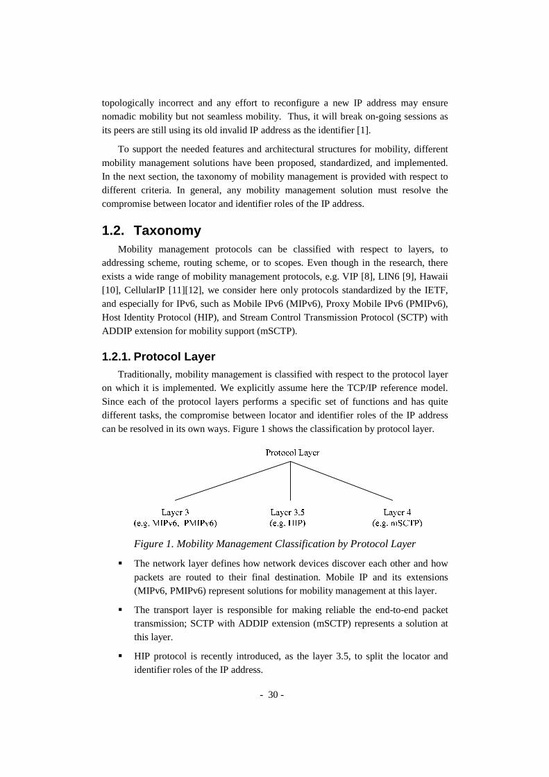
- 30 -
topologically incorrect and any effort to reconfigure a new IP address may ensure nomadic mobility but not seamless mobility. Thus, it will break on-going sessions as its peers are still using its old invalid IP address as the identifier [1].
To support the needed features and architectural structures for mobility, different mobility management solutions have been proposed, standardized, and implemented. In the next section, the taxonomy of mobility management is provided with respect to different criteria. In general, any mobility management solution must resolve the compromise between locator and identifier roles of the IP address.
1.2. Taxonomy Mobility management protocols can be classified with respect to layers, to
addressing scheme, routing scheme, or to scopes. Even though in the research, there exists a wide range of mobility management protocols, e.g. VIP [8], LIN6 [9], Hawaii [10], CellularIP [11][12], we consider here only protocols standardized by the IETF, and especially for IPv6, such as Mobile IPv6 (MIPv6), Proxy Mobile IPv6 (PMIPv6), Host Identity Protocol (HIP), and Stream Control Transmission Protocol (SCTP) with ADDIP extension for mobility support (mSCTP).
1.2.1. Protocol Layer Traditionally, mobility management is classified with respect to the protocol layer
on which it is implemented. We explicitly assume here the TCP/IP reference model. Since each of the protocol layers performs a specific set of functions and has quite different tasks, the compromise between locator and identifier roles of the IP address can be resolved in its own ways. Figure 1 shows the classification by protocol layer.
Figure 1. Mobility Management Classification by Protocol Layer
� The network layer defines how network devices discover each other and how packets are routed to their final destination. Mobile IP and its extensions (MIPv6, PMIPv6) represent solutions for mobility management at this layer.
� The transport layer is responsible for making reliable the end-to-end packet transmission; SCTP with ADDIP extension (mSCTP) represents a solution at this layer.
� HIP protocol is recently introduced, as the layer 3.5, to split the locator and identifier roles of the IP address.

- 31 -
1.2.2. Addressing Scheme By addressing scheme (see Figure 2), we mean how the locator and the identifier
are defined and separated. It ensures that a MN can be identified by both the routing protocol and the upper-layer.
Figure 2. Mobility Management Classification by Addressing Scheme
� Mobile IP uses a two-tier addressing scheme with the Home Address (HoA) and the Care-of-address (CoA): The HoA is a routable address, serves as the upper-layer identifier, and remains static during the mobility; the CoA reflects the actual point of attachment of the MN and dynamically changes whenever the MN moves to a new network. As regards PMIPv6 the IP address of the attached access router is used as the CoA within the PMIPv6 domain.
� HIP protocol introduces the Host Identity Tag (HIT) as the upper-layer identifier. The HIT is mapped and translated to the routable address of the MN which, in turn, reflects the actual point of attachment of the MN and dynamically changes with respect to MN movement.
� MSCTP allows the addresses to be dynamically updated through the ADDIP extension. The soft state of the transport association will be synchronized with efforts to reconfigure a new IP address at IP layer, and therefore can keep the ongoing sessions during the mobility.
1.2.3. Routing Scheme By routing scheme, we mean how IP packets are forwarded to and from the MN
correctly, during MN’s movement, with respect to prefix model. For each prefix model, the routing decision can be done in a per-host manner or in a per-prefix manner as in Figure 3.

- 32 -
Figure 3. Mobility Management Classification by Routing Scheme
� In general, a prefix is assigned to the link and shared by all the nodes on that link. HIP and mSCTP only require normal routing infrastructure with per-prefix routing decision. On the other hand, MIPv6 uses IP tunneling (IP-in-IP encapsulation [13]) with per-host routing decision and maintains per-host routing entries at the HA and the MN to override the normal behavior of per-prefix routing of the infrastructure (thanks to the longest prefix match rule).
� Per-MN prefix model is a special case which is recently proposed for PMIPv6. This model respects constrains defined by the IETF for the relationship between link and prefix (subnet). The routing decision is considered as both per-prefix and per-host because one per-prefix routing entry corresponds to the route of one MN.
1.2.4. Architectural Impact Impact of mobility management on the network entities can also be used for
classification. It answers how mobility-supporting functionalities are distributed in the architecture. It reveals which network entities must be modified to participate in the mobility management protocol. With respect to this fact, there are principally two categories as shown in Figure 4: host-based mobility management, network-based mobility management.
Figure 4. Mobility Management Classification by Architectural Impact

- 33 -
� A host-based solution requires changes in the host software stack, and that the host is involved in the mobility signaling. A host-based solution can be implemented in an end-to-end manner, in which the mobile host informs its correspondent host about the address changes (as in HIP, mSCTP), or via third-party entities, in which the mobile host informs the third-party entities to redirect packets to and from the mobile host (as in MIPv6).
� In a network-based solution, e.g. CellularIP [11][12] or Hawaii [10], the mobility service is handled only by network entities, either core entities or edge entities, without any involvement of the end host. Edge-based solution, e.g. PMIPv6, is a special case of network-based solution where only edge network entities are involved in the protocol; neither the end host nor the core network entities need to participate.
1.2.5. Mobility Management Scope With respect to the scope, mobility management can be divided into Global
Mobility Management (GMM) and Localized Mobility Management (LMM) as illustrated in Figure 5.
Figure 5. Mobility Management Classification by Scope
� A GMM protocol is a mobility protocol used by the mobile node to change the global, end-to-end routing of packets for purposes of maintaining session continuity when movement causes a topology change, thus invalidating a global unicast address of the mobile node. This protocol could be MIPv6, but it could also be HIP, mSCTP or MOBIKE [14].
� As regards LMM, it is a generic term for any protocol that maintains the IP connectivity and reachability of a mobile node for purposes of maintaining session continuity when the mobile node moves, and whose signaling is confined to an access network. An example of LMM could be PMIPv6, HMIPv6, CellularIP or Hawaii.

- 34 -
1.3. Multi-homing Consideration
1.3.1. Concepts and Taxonomy Multi-homing refers to the situation in which a host has more than one IP address.
This may occur for a host using either a single interface or several interfaces: in the first case the host’s interface is assigned several addresses, in the second case each host’s interface can be assigned one or more global IP addresses (from different subnets) [15]. The scenario of having one network interface with multiple addresses has not been the norm in the IPv4 Internet, but will be perfectly ordinary in the coming IPv6 Internet. Even if the additional addresses are not globally routable, it still creates a multi-homing scenario where issues such as source address selection takes on new importance.
There are several levels of multi-homing: Provider level multi-homing, site level multi-homing or host level multi-homing. The different addresses can be from the same Internet Service Provider (ISP) or from several ISPs. The consequences are on the host but also potentially on the site or the providers depending on the policy used to assign the IP addresses.
A typical multi-homing scenario is illustrated in Figure 6. Multi-homing is a common need of many medium-sized networks, including many businesses and ISPs, and can occur for two main reasons. One reason is for link redundancy, allowing a site to retain connectivity when one of the links fails. The other main reason is for optimal use of the links, for example increasing bandwidth, or for Quality of Service (QoS) factors, such as routing traffic over the topographically closest link to minimize delay, or routing low priority traffic over the cheapest link. In addition, new developments in distributed, pervasive computing may lead to mobile devices being transiently multi-homed, and also a site may be temporarily multi-homed during a change in upstream provider.

- 35 -
Figure 6. A typical multi-homing scenario
The second host multi-homing configuration is having more than one interface. Although the bandwidth of network technologies in general has been rising faster than the speed of the computers that interconnect them, increased network bandwidth is a common reason for equipping a computer with multiple network interfaces. The reason is that the cost of two low bandwidth connections is often cheaper than one high bandwidth.
1.3.2. Multi-homing benefits The current motivations for exploring multi-homing can be roughly divided into
five different areas: fault-tolerance, load sharing, provider selection, eased renumbering transition, enhanced mobility support [16].
Fault-tolerance is probably the most important benefit in the sense that anyone investing in a multi-homing solution will at least expect to gain this. The simplest form of fault tolerance consists of using one network connection during normal operation and migrate traffic to another when the link become unusable. There are many reasons why a link might go down in the Internet, including physical wire cuts, router crashes, power outages and configuration errors. With the Internet becoming more and more important to both businesses and organizations, we expect that more and more people will be willing to invest in redundant Internet connections for purposes of fault tolerance.
Examples of failure modes from which an enterprise can obtain some degree of protection by multi-homing are:
� Physical link failure, such as a fiber cut or router failure

- 36 -
� Logical link failure, such as a misbehaving router interface
� Routing protocol failure, such as a Border Gateway Protocol (BGP) peer reset
� Transit provider failure, such as a backbone-wide Interior Gateway Protocol (IGP) failure
� Exchange failure, such as a BGP reset on an inter-provider peering
Load sharing is also a very important motivation. Bandwidth demands of Internet applications are increasing rapidly; some examples are World Wide Web, multimedia on demand, IP telephony, file transfer, video conferencing and so forth. Very high bandwidth single-wire solutions like fiber optic cable are available, but often at prohibitively high cost (especially in cases of under-sea cable deployments). Multiple low bandwidth connections are a viable alternative which will in many cases create multi-homing scenarios. Traffic load distribution can be realized at several levels, from simple random load sharing, to advanced calculated load balancing.
The third benefit, provider selection, is already present in the IPv4 Internet of today, but is expected to become even more of an issue in the IPv6 Internet of tomorrow. It is fairly common today for Internet users to have multiple dial-up ISPs configured and alternate between them. However, in these cases users tend to only use one ISP at a time, thus not creating a real multi-homing scenario. With connection prices constantly dropping, this is expected to change, and there is also a trend towards high bandwidth, always online connections such as Digital Subscriber Line (DSL) and cable Internet. In addition to expecting fault tolerance and load sharing, users may wish to alternate between different Internet links depending on such factors as time of day and current traffic load, in order to optimize the cost versus QoS equation.
The fourth benefit, eased renumbering transition, is particularly interesting because of the new mechanisms for renumbering networks introduced with IPv6. Renumbering an IPv4 network is usually a major chore, involving work on every individual host. The process can be made easier if solutions such as Dynamic Host Configuration Protocol (DHCP) [17] are deployed. During a network renumbering, hosts will have multiple addresses, creating a multi-homing scenario where benefits such as migrating transport layer connections transparently would be very welcome.
As for enhanced mobility support, Mobile IP networks almost invariably create multi-homing scenarios both in the case of moving between heterogeneous networks, such as from WLAN to 3GPP, or when moving from one WLAN to another. Often such a change involves an overlap period where the mobile host is attached to multiple networks with different addresses. Mobile IP is one of the areas where the most growth is expected in the coming years, as more and more people acquire portable computers and (PDAs). Naturally, a lot of research effort [18][19] is therefore going into this area, and better multi-homing solutions are an important part of this.

- 37 -
1.3.3. Multi-homing versus Mobility Multi-homing and mobility protocols both work with multiple addresses. However
multi-homing support simultaneous use of multiple addresses which are normally unchanged, while mobility support alternative use of multiple addresses which are changed frequently due to the movement of MNs.
At IETF, MOBIKE working group concentrates on mobility issues for Virtual Private Network (VPN) connections. MULTI6 working group focuses on site multi-homing for IPv6. MONAMI6 working group focuses on extension to Mobile IP in order to provide several CoA in the Home Agent and the mobile nodes. The MONAMI6 working group takes into consideration the simultaneous use of several interfaces. Some IETF protocols which aims at multi-homing are: HIP, SCTP, MOBIKE, SHIM6 [20].
Figure 7. Multi-homing and Mobility protocol portfolios
7space of Multi-homing and Mobility, each protocol is represented by a node of which shape reflects the protocol layer: the square node represents a solution at layer 4, the round node represents a solution at layer 3.5 and the triangular node represents a layer 3 solution. Some of them (MONAMI6-supported MIP, mSCTP, HIP, MOBIKE) are designed to have both features and are standard tracks for the future mobile Internet.

- 38 -
2. IETF Mobility Management Protocols
2.1. Mobile IPv6
2.1.1. Overview Mobile IP is the IETF standard for supporting host mobility on the Internet. Mobile
IP does not require a redesign of the IP routing infrastructure. The protocol offers transparent movement of a Mobile Node (MN) to transport and higher-level protocols and applications suitable for both homogenous and heterogeneous media. Mobile IPv4 (MIPv4) is documented in RFC 3344: “IP Mobility Support in IPv4” [21]. Mobile IPv6 (MIPv6) relies on IPv6 and is documented in the RFC 3375: “Mobility Support in IPv6” [22]. For the related terminology, see [23].
The basic principle of this approach is a two-tier addressing schema using a couple of IP addresses to identify the mobile node and manage its movements. Each mobile node is always identified by its Home Address (HoA), regardless of its current point of attachment to the Internet. While situated away from its home, a mobile node is also configured with a Care-of Address (CoA), which provides information about the mobile node’s current location. The Correspondent Node (CN) sees only the host’s HoA and has no indication that the host is mobile, or what its current network attachment point might be.
2.1.2. Protocol Descriptions MIPv4 introduces Home Agents (HA) in the home network and Foreign Agents
(FA) in foreign networks. The HA stores all MNs bindings in special table termed Binding Cache (BC). It is used to locate the mobile at each moment. FA is a special router that manages the MN connected to the foreign link. When a correspondent send packets to the MN it uses its home address, located in the HA sub network, so this one will be able to intercept and encapsulate MN destination packets towards the suitable FA or access router, in an IPv4 tunnel.
As regards MIPv6, FA is not used. Instead, the MN register its new CoA with the HA while situated away from its home. The HA can then create a binding between the MN HoA and its new CoA. The registration process requires IPsec [24][25][26] to protect binding updates; so having IPsec is mandatory. MIPv6 can use Route Optimization (RO) as well as tunneling.
Hierarchical Mobile IPv6 (HMIPv6) [27] is an extension of MIPv6 to support localized mobility management. This HMIPv6 scheme introduces a new function, the Mobility Anchor Point (MAP) which plays the role of a local HA, and minor extensions to the MN operation. The CN and HA operation is not affected by this extension.

- 39 -
2.1.3. Shortcomings Although many security-related issues have been dealt with in MIPv6, some
problems still exist. One of these is the possibility of a Denial of Service (DoS) attacks if a malicious peripheral deploys false binding updates. As the HA is still needed for initialization of new connections and acts as a single point of failure; no mobile host is connectible if there is a problem connecting to the HA of the host. Secondly, the design of MIPv6 requires modification in both MN and HA. In case of route optimization, the remote host in the Internet must be modified as well. This fact requires efforts from not only network operators but also mobile device manufacturers in the deployment. Furthermore, the handover process may take long time and result in packet loss and degradation of quality of service during the handover if multi-homing is not considered to improve the performance.
2.2. Host Identity Protocol
2.2.1. Overview The basis of HIP [28][29][30], proposed by R. Moskowitz and P. Nikander, is the
separation of host identity from host location so that a network host could be referred independent of its current location. HIP introduces a new Host Identity layer (layer 3.5) between the IP layer (layer 3) and the upper layers.
Figure 8. The difference between the bindings of the logical entities
As shown in Figure 8, in HIP, the hosts are identified with public keys, not IP addresses. A typical Host Identity (HI) is a public cryptographic key of an asymmetric key-pair. A Host Identity Tag (HIT) is a 128-bit hash of the host’s public key. The transport layer uses Host Identity Tags in place of IP addresses (as the end-point identifier), while the interface to the Internet layer uses conventional IP addresses (as the locator). Each host will have at least one HI that can either be public or anonymous. It is important to understand that the end-point names based on Host Identities are slightly different from interface names; a Host Identity can be simultaneously reachable through several interfaces. The purpose of HIP is to support trust between systems, enhance mobility, and greatly reduce the DoS attacks.

- 40 -
2.2.2. Protocol Descriptions It is possible that a single physical computer hosts several logical end-points.
With HIP, each of these end-points would have a distinct Host Identity. A HIP node stores in the Domain Name System (DNS) its Host Identity (HI) which is the public component of the node public-private key pair, its Host Identity Tag (HIT) which is a truncated hash of its HI, and the Domain Name or IP addresses of its Rendezvous Servers (RVS) [31].
Figure 9. The HIP packet structure
HIP introduces a new packet structure, illustrated in Figure 9: The transport layer packet, e.g. TCP, must be enclosed with a HIP header, which contains the HIT. HIP could be carried out in every datagram throughout the connection but alternatively the HIP payload can be compressed into an Encapsulating Security Payload (ESP) [26] after the HIP exchange. Thus, HIP packets are only needed to establish an authenticated connection. As mentioned above, the HIP protocol is used to authenticate the connection. In addition to authentication, the procedure establishes Security Associations for a secure connection with IPsec ESP.
By definition, the system initiating a HIP exchange is the Initiator, and the peer is
the Responder. This distinction is forgotten once the HIP exchange completes, and either party can become the initiator in future communications. The HIP Base Exchange, illustrated in Figure 10, is described as follows. HIP starts with one of the hosts looking up the HI and IP of the peer in the DNS: upon query by an application for the IP address lookup from a Full Qualified Domain Name (FQDN), the resolver would then additionally perform an additional lookup to find the HI from the FQDN, and use it to construct the resulting mapping from the HI to the IP address. The host then sends an initial I1 message requesting a state to be established with the peer. Messages R1, I2 and R2 are exchanged successively in order to create an association.
The HIP Base Exchange is protected with HIP Cookie mechanism, Authenticated Diffie-Hellman protocol and HIP replay protection. The last three packets of the exchange, R1, I2, and R2, constitute a standard authenticated Diffie-Hellman key exchange for session key generation. During the Diffie-Hellman key exchange, a piece of keying material is generated. The HIP association keys are drawn from this keying material. If other cryptographic keys are needed, e.g., to be used with ESP, they are expected to be drawn from the same keying material. In Figure 10, the term "key" refers to the Host Identity public key, and "sig" represents a signature using such a key.
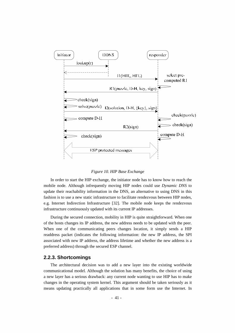
- 41 -
Figure 10. HIP Base Exchange
In order to start the HIP exchange, the initiator node has to know how to reach the mobile node. Although infrequently moving HIP nodes could use Dynamic DNS to update their reachability information in the DNS, an alternative to using DNS in this fashion is to use a new static infrastructure to facilitate rendezvous between HIP nodes, e.g. Internet Indirection Infrastructure [32]. The mobile node keeps the rendezvous infrastructure continuously updated with its current IP addresses.
During the secured connection, mobility in HIP is quite straightforward. When one of the hosts changes its IP address, the new address needs to be updated with the peer. When one of the communicating peers changes location, it simply sends a HIP readdress packet (indicates the following information: the new IP address, the SPI associated with new IP address, the address lifetime and whether the new address is a preferred address) through the secured ESP channel.
2.2.3. Shortcomings The architectural decision was to add a new layer into the existing worldwide
communicational model. Although the solution has many benefits, the choice of using a new layer has a serious drawback: any current node wanting to use HIP has to make changes in the operating system kernel. This argument should be taken seriously as it means updating practically all applications that in some form use the Internet. In

- 42 -
addition, a change of this magnitude has never before been attempted, and the architecture of the layers has remained the same for decades. Thus, the main problem with HIP may not be a technical one but rather a marketing issue.
A much more modest problem is related to the features of HIP: the current specification of HIP does not support multicasting. Including this new feature of course means modifications to the protocol. With current trends moving towards the increased usage of multicasting, this issue almost inevitably has to be addressed if HIP wants to be one day the de facto mobility solution.
The build in security considerations raise yet another problem for HIP. As the HIP namespace is cryptographic in nature and the public keys are used in the connection establishment, heavy computations are needed. This presents a problem especially for mobile devices with limited CPU power. The impact is reflected as slower connection establishment.
2.3. Mobile Stream Control Transmission Protocol
2.3.1. Overview The Stream Control Transmission Protocol (SCTP) [33][34] is standardized by the
IEFT as a reliable transport protocol over IP networks. One of the core features of SCTP is supporting multi-homing. It has the ability for a single SCTP endpoint to support multiple IP addresses. To support multi-homing, SCTP endpoints exchange lists of addresses during initiation of the connection. This multi-homing feature enables SCTP to be used for Internet mobility support without any support of network routers or special agents. Due to its attractive features such as multi-streaming and multi-homing which promise load balancing ability [35], SCTP has received much attention from the network community, in terms of both research and development.
A single message transmitted over an SCTP association from the originating host to the destination host will be sent using a single destination IP address chosen from the set of destination IP addresses available for that association. The paths used by the IP packets across the network might be different depending on the destination IP address. If a message fails to reach its destination, SCTP may retransmit the message using a different destination IP address.
An SCTP packet is composed of a 12 byte common header and chunks. In the header, a 32-bit checksum is used to detect transmission errors. SCTP packets with an invalid checksum are silently discarded. A randomly created 32 bit verification tag allows a receiver to verify that the SCTP packet belongs to the current association and not to an old one. The chunk on the other hand may contain either control information or user data. Chunks have variable length and there are currently 13 types of them in standard use. Multiple chunks can be bundled into one SCTP packet up to the MTU size, except for the INIT, INIT ACK, and SHUTDOWN COMPLETE chunks.

- 43 -
Figure 11. A schematic view of an SCTP association
SCTP extended with the ADDIP extension is called mobile Stream Control Transmission Protocol (mSCTP) [36][37]. The ADDIP extension enables an mSCTP endpoint to add a new IP address or delete an unnecessary IP address, and also to change the primary IP address used for the association during an on-going session. When one of these events occurs, the mSCTP endpoint will notify the corresponding event to the remote endpoint by sending an Address Configuration Change (ASCONF) chunk and wait for Address Configuration Acknowledgment (ASCONF ACK) from the remote endpoint. There are seven new parameters: Set Primary Address, Adaptation Layer Indication, Supported Extensions, Add IP Address, Delete IP Address, Error Cause Indication, and Success Indication.
2.3.2. Protocol Descriptions The association establishment in mSCTP, as in SCTP, uses the four-way
handshake as shown in Figure 12. The passive side is called a server and the other is a client. The handshake procedure is as follows: First, the server receives an INIT chunk. Using its data, the server generates a secure hash of these values and a secret key. These values along with a MAC are put into a COOKIE, and returned in an INIT-ACK chunk. The client using the received COOKIE assembles a COOKIE-ECHO chunk and returns it to the server. Finally, the server verifies with the MAC, that the COOKIE is the same as it sent, and replies with a COOKIE-ACK chunk.

Figure
Now the association is established. When one of the communicating parties wants to end the association, it can be done in two ways: Either by graceful shutdown, ensuring that no data is lost, or hard termination (abort), not taking care of the peer. Unlike TCP, when either endpoint performs a shutdown, both of the endpoints stop accepting data.
During association startup, a list of transport addresses (i.e. IP addressis provided between the communicating entities. These addresses are used as the endpoints of different streams. source/destination combinations. Also one of the addresses is selected as initial primary path, which may be changed later if needed.
The mSCTP handover needs to be triggered by the mobile node because only the mobile node knows the movement of itself andnew access routers. Figure initiated an mSCTP association with the CN. The resulting association consists of IP address @1 for MN and IP address @decides to move to a new are repeated every time MN moves into a new location:
� Step 1: Obtaining an IP address for new location.
another access routerMN obtains the new IP address from the DHCPv6 [17] or IPv6
- 44 -
Figure 12. SCTP association setup message sequence
Now the association is established. When one of the communicating parties wants he association, it can be done in two ways: Either by graceful shutdown,
ensuring that no data is lost, or hard termination (abort), not taking care of the peer. Unlike TCP, when either endpoint performs a shutdown, both of the endpoints stop
During association startup, a list of transport addresses (i.e. IP addressis provided between the communicating entities. These addresses are used as the endpoints of different streams. Association spans transfers over all of the possible source/destination combinations. Also one of the addresses is selected as initial primary path, which may be changed later if needed.
The mSCTP handover needs to be triggered by the mobile node because only the mobile node knows the movement of itself and the signal strength from the old and
Figure 13 shows a typical mSCTP handover process. SCTP association with the CN. The resulting association consists of IP
for MN and IP address @CN for CN (the primary path). After a while, MN to a new access router and configure address @2. The following steps
are repeated every time MN moves into a new location:
Step 1: Obtaining an IP address for new location. As MN is moving towards ss router, at some point it reaches the overlapping region. Then
MN obtains the new IP address from the new access router with the help of or IPv6 stateless address auto-configuration [38].
Now the association is established. When one of the communicating parties wants he association, it can be done in two ways: Either by graceful shutdown,
ensuring that no data is lost, or hard termination (abort), not taking care of the peer. Unlike TCP, when either endpoint performs a shutdown, both of the endpoints stop
During association startup, a list of transport addresses (i.e. IP address-port -pairs) is provided between the communicating entities. These addresses are used as the
ssociation spans transfers over all of the possible source/destination combinations. Also one of the addresses is selected as initial
The mSCTP handover needs to be triggered by the mobile node because only the the signal strength from the old and
shows a typical mSCTP handover process. The MN has SCTP association with the CN. The resulting association consists of IP
imary path). After a while, MN . The following steps
As MN is moving towards , at some point it reaches the overlapping region. Then
ccess router with the help of

- 45 -
� Step 2: Adding the new IP address to the SCTP association. MN informs CN of the new address by sending an Address Configuration Change (ASCONF) chunk. As a reply the ASCONF-ACK is sent.
� Step 3: Changing the primary IP address. While MN further continues to move towards the new access router, it needs to set the new address as its primary address. The changing of addresses is done according to specific rules, for example as soon as a new IP address is detected. However, the configuration of this change triggering rule is a challenging issue for mSCTP.
� Step 4: Deleting the old IP address. As MN has totally moved away from the old access router, the old IP address becomes inactive, and it is deleted from the address list. The knowledge from underlying layers can be used to determine when the address becomes inactive.
Figure 13. An mSCTP handover scenario
2.3.3. Shortcomings The mobility presents its own minor problems to mSCTP. The protocol is mainly
targeted for client-server services, in which the MN initiates the session with a fixed server. For supporting peer-to-peer services, the mSCTP must be used along with an additional location management scheme, e.g. MIPv4 or MIPv6. As for seamless

- 46 -
handover, more work needs to be done in the test and implementation to make it work as expected.
Performance in wireless environments can also cause problems for mSCTP. The protocol assumes that all losses are caused by congestion despite the fact that higher bit error rates and more frequent delay spikes are encountered in wireless networks. This will cause mSCTP to back-off unnecessarily, and result in poor throughput.
Another problematic issue arises when the underlying network operates on IPv6. Certain address types supported by IPv6 are not routable (i.e. link-local) or reachable outside of specific domains (i.e. site-local). If a peer lists one of these addresses to a peer that has no connectivity to that address, an association could self-destruct and create a black hole effect.
2.4. Network-based Localized Mobility Management
2.4.1. Overview Although host-based mobility management (MIPv6, HIP, mSCTP) are already
matured, practically there are zero deployments of these protocols. It is due to the fact that a host-based mobility management solution requires host stack changes, thus the associated software and resource requirements on the host has become a primary obstacle for universal adoption and deployment.
Recognizing the success in the WLAN infrastructure market of WLAN switches, which perform localized management without any host stack involvement, a similar paradigm is suggested to reduce host stack software complexity, and can accommodate diverse GMM protocols. From the deployment point of view, this means that the mobility service can be provided to a wider range of mobile nodes. In network-based mobility management, the network, on detecting that the MN has changed its point of attachment, provides the MN with the same IP address that it had at its previous point of attachment. The network entity providing the IP address to the MN also handles updating the mobility anchor in the network so that the packets arrive at the new point of attachment of the MN. The MN is not aware of the mobility management signaling within the network.
PMIPv6, standardized within the Network-based Localized Mobility Management (NetLMM) IETF working group [39][40][41], enables network-based mobility management since it is possible to support mobility for MNs having standard IPv6 stack without MN involvement by extending MIPv6 signaling messages and reusing the home agent. PMIPv6 aims at solving the 3 following problems: Update latency, Signaling overhead and Location privacy.
2.4.2. Architecture The NetLMM architecture consists of Mobile Access Gateways (MAGs) and the
Local Mobility Anchor (LMA). The main role of the MAG is to detect the MN’s

- 47 -
movements and initiate mobility-related signaling with the MN’s LMA on behalf of the MN. In addition, the MAG establishes a tunnel with the LMA for enabling the MN to use an address from its home network prefix and emulates the MN’s home network on the access network for each MN. On the other hand, the LMA is similar to the HA in MIPv6. It is responsible for maintaining the MN’s reachability state and is the topological anchor point for the MN’s home network prefix. However, it has additional capabilities required to support PMIPv6. The LMA includes a binding cache entry for each currently registered MN. The binding cache entry maintained at the LMA is more extended than that of the HA in MIPv6 with some additional fields such as the MN-Identifier, the MN’s home network prefix, a flag indicating a proxy registration, and the interface identifier of the bidirectional tunnel between the LMA and MAG, etc. Such information associates the MN with its serving MAG, and enables the relationship between the MN, the MAG and the LMA to be maintained.
NetLMM defines two interfaces. The first one defines the interaction between MNs and MAGs while the second one defines the interaction between MAGs and the LMA (see Figure 14). The interface between the MN and the MAG can be realized with Detecting Network Attachment (DNA) [42], Neighbor Discovery Protocol (NDP) [43] and Secure Neighbor Discovery (SEND) [44] for stateless address auto-configuration or with the help of DHCP for stateful address configuration. The interface between the MAG and the LMA is realized with Proxy Mobile IPv6.
Figure 14. Protocol stack for NetLMM solution
The NetLMM addressing mechanism is Cryptographically Generated Address (CGA) [45] which provides a mean to secure the mobility. Within the Internet addressing model, the terms link and subnet have a tight relationship; their generally admitted definitions are:
� Link is a topological area of an IP network delimited by routers

- 48 -
� Subnet is a topological area of an IP network that uses the same unsubdivided address prefix.
The consensus in the IETF has been, and remains, that the relationship between link and subnet is one-to-many. It means that a link can be assigned with multiple subnets but one subnet can spans only one link. Due to this constraint, the addressing model within NetLMM has been decided to be per-MN subnet model, in which a unique prefix must be assigned by the NetLMM fabric to each MN in the domain. The data plane is supposed to use a tunneling mechanism (IP tunneling, GRE, MPLS).
2.4.3. MN-MAG Interface The MN-MAG interface [46] is used between a MN node and an MAG of a
NetLMM domain. In the absence of link-layer specific mechanism, it has to rely only on standards track IPv6 protocols such as ND, SEND, and DNA and allows the MAG to detect the network attachment of a MN by inspecting Internet Control Message Protocol (ICMP) messages. It then provides movement detection triggers to update routing at the MAG and LMA so that the MN stays reachable when it roams across the NetLMM domain.
The interface has two functions which are invoked when a MN attaches and detaches from a MAG. The attachment function lets the MAG authenticate the MN identifier, does address and default router configuration for the MN. Upon any attachment of an MN, the MAG starts the Location Registration procedure. The MAG informs the LMA about the new MN by sending a Proxy Binding Update to the LMA and wait for a Proxy Binding Acknowledgement to add the new MN identifier in its cache.
The detachment function lets the MAG detect that the MN has left so that it starts the Location Deregistration procedure to deregister the MN at the LMA. Upon any detachment, the MAG sends a Proxy Binding Update message with lifetime of zero to update information at the LMA and release occupied resource at the MAG.
It is recommended that the proposed interface must only be used in deployments where the link between the MN and the MAG is point-to-point. The interface must not be used in deployments where the link between the MN and the MAG is shared and/or multi-access. Besides, it is the MN which has to detect the link change. It also has to verify if the MAG has changed by sending a Router Solicitation (RS) and determine if the MAG has changed based on the Router Advertisement (RA). As a consequence, it requires certain modifications at the layer-2 device driver.
2.4.4. MAG-LMA Interface (PMIPv6) Figure 15 shows a typical PMIPv6 handover process of an IPv6 MN. Once a MN
enters the PMIPv6 domain and attaches to a MAG, the MAG must identify the MN and acquire the Mobile Node Identifier (MNID). If the MAG determines that the MN is authorized for the network-based mobility management service, it must start the

- 49 -
Location Registration procedure on behalf of the MN to maintain the reachability of the MN. The MAG sends Proxy Binding Update (PBU) message to the LMA and waits for the Proxy Binding Acknowledgement (PBA) message from the LMA. At the end of this Location Registration procedure, the MAG and the LMA establish a bidirectional tunnel and update the routing entry to forward the MN traffic through the bidirectional tunnel. The soft state of a MN at the LMA ad MAGs is maintained in a Binding Cache entry which can be accessed using the Mobile Node Identifier (MNID) as search key. Such information associates a MN with its serving MAG, and allows the relationship between the MAG and the LMA to be maintained.
At any point, the MAG detects that the MN has moved away from its access link, or if it decides to terminate the mobility session, it should start the Location Deregistration procedure by sending a Proxy Binding Update message to the LMA with the lifetime value set to zero.
Figure 15. Proxy Mobile IPv6 Sequence Diagram
2.4.5. Shortcomings Scalability is one of the main weaknesses of the base PMIPv6. The centralized
LMA is a single point of failure, especially when taking into account large scale access networks. If the LMA crashes for some reason, the mobility service in the whole access network is disrupted.
Besides, the base PMIP6 is mainly targeted to infrastructural network; the

- 50 -
addressing model within NetLMM has been decided to be per-MN subnet model. For a heterogeneous environment converging both infrastructural and ad-hoc networks, researchers need to consider PMIPv6 with the shared prefix addressing model as well.
Routing performance presents its own problem to PMIPv6. The base PMIPv6 protocol doesn’t consider the Route Optimization (RO) support for communication between MNs in the same PMIPv6 domain. Whether the CN is outside the PMIPv6 domain or is managed by PMIPv6 within the domain, the traffic is always routed in the same manner through the LMA regardless the position of the CN. Thus causes a suboptimal route.
3. Conclusions Future mobile Internet typically consist of multi-homed mobile terminals and
wireless overlay networks in heterogeneous access technologies and aim at the Always Best Connected provision. In such environments, the multi-homing feature and mobility feature are inseparable. Both multi-homing and mobility have to cope with the same problem of multiple IP addresses. However the former works simultaneously on multiple simultaneous IP addresses while the later works alternatively on multiple dynamic IP addresses.
This chapter provided an up-to-date picture of current mobility management and the trends, including many works in progress of IETF, which support mobility management with consideration of multi-homing features (MIPv6, HIP, mSCTP). As the goal of each IETF protocol are different, mobility management and multi-homing are considered in different ways. However, they all co-exist to construct the future Mobile Internet for Next Generation Networks.
Nevertheless, pervasive mobility service on the Internet anytime anywhere is still not a reality. There are many reasons, among which, deployment complexity is a big obstacle. In fact, these mobility management protocols are host-based and require host stack changes, not only from the side of mobile devices themselves but also from the side of their correspondent nodes. This requirement has become a primary hurdle for the protocol adoption.
As the PMIPv6 is based on Network-based Mobility Management paradigm, it minimizes host stack software complexity, facilitates the protocol deployment and improves the handover performance. It will be the key protocol for achieving inter-working between various access technologies in the future mobile Internet. In the rest of this thesis, we will investigate different topics around PMIPv6, including scalability, RO, and multi-homing in PMIP6.

- 51 -
CHAPTER 3 - SCALABLE PROXY MOBILE IPV6
This chapter firstly explores the hierarchical mobility management architecture
which can provide scalability for mobility management in infrastructural networks, and then proposes a concept of cluster-based architecture which decomposes the network into clusters and allows scaling up the PMIPv6 domain in spontaneous wireless mesh networks where the topology can be dynamically created and changed in an ad-hoc manner. We propose an extension of PMIPv6 for supporting scalability, denoted Scalable Proxy Mobile IPv6 (SPMIPv6). The SPMIPv6 extension provides the inter-LMAs interaction which allows increasing the size of the PMIPv6 domain horizontally by adding new clusters gradually. Furthermore, it also supports the share prefix model and provides a mechanism to locate serving entities of a registered MN which will be beneficial for supporting Route Optimization and QoS in later research. We then analyze the scalability of the extension through numerical analysis. The experimental evaluation for the SPMIPv6 is provided later in Chapter 5.
1. Problem Overview PMIPv6 basically requires changes only to edge routers; the serving network is
regarded as an edge domain within which the MN acquires and keeps the same IP address while moving. As PMIPv6 requires no modification to the IPv6 stack of the MN, it is very promising to support mobility service to a wide range of users. However, as all the intelligence is delegated to the network, the scalability becomes questionable. Scalability can be defined as the ability of a network to adjust or maintain its performance as the size of the network increases and the demands made upon it become greater and greater.
The network size in terms of the radio coverage, i.e. the covered geographical area, is an important metric to reflect the wireless network capacity. For a given access technology, the radio coverage is limited and requires a solution for extending the coverage of the access networks to allow mobile users to be always connected. This

- 52 -
technique, called communications coverage extension, has been deeply deployed in military communications, in public safety as well as by network operators. Providing an efficient solution to this problem is not trivial at all.
As regards the demand, it is proportional with the number of mobile users with the assumption that all mobile users are active. For a given MN density, the number of mobile users proportionally increases with the covered geographical area, and thus, a larger geographical area means that the LMA has to serve more users. Similarly, given a geographical area, a higher MN density means a higher number of mobile users which the LMA has to serve. If the LMA becomes overloaded, the performance decreases dramatically. Moreover, a centralized LMA is a single point of failure in the access network; if the LMA crashes for some reason, the mobility service in the whole network is disrupted.
In the literature, the scalability is usually classified into two classes: horizontal scalability and vertical scalability. Horizontal scalability refers to the network’s ability to grow efficiently and cost-effectively in terms of geographical coverage, while vertical scalability stands for the ability to efficiently support an increasing number of users by replacing the old system with a more powerful system. Scalability is a key
success factor for business applications in a dynamic environment. In the real world, savvy corporations combine vertical scalability and horizontal scalability. They can start with a large vertical architecture, adding resources as-needed. If continuous availability is still required, and the single LMA is approaching its capacity, they can scale up the network with the horizontal scalability.
2. Hierarchical Mobility Management Architecture Hierarchy is always a proper solution to archive the scalability for networking. A
hierarchical architecture in mobility management allows differentiate the scopes of mobility in order to enhance the performance of mobility management. It significantly reduces the amount of signaling load on the Internet, and the handover latency, therefore minimizes the loss of packets that may occur during transition. Furthermore, it provides location privacy to MN by allowing mobile nodes to hide their location from correspondent nodes and higher-scope entities.
The mobility management architecture for future mobile Internet is a hierarchical two-tier architecture, in which the mobility management is divided into Global Mobility Management (GMM) and Localized Mobility Management (LMM). While moving, GMM and LMM assure the session continuity between the Correspondent Node (CN) and the Mobile Node (MN). LMM is used for the mobility inside a Localized Mobility Domain (LMD); while GMM is used for the global mobility
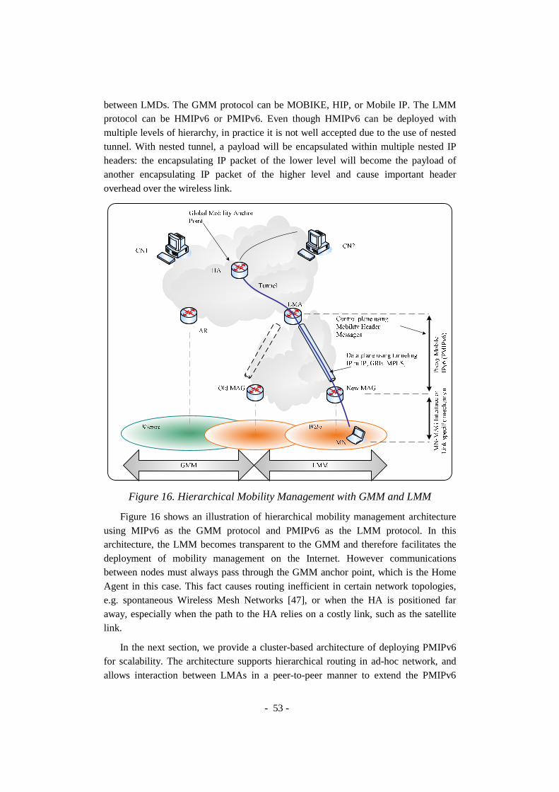
- 53 -
between LMDs. The GMM protocol can be MOBIKE, HIP, or Mobile IP. The LMM protocol can be HMIPv6 or PMIPv6. Even though HMIPv6 can be deployed with multiple levels of hierarchy, in practice it is not well accepted due to the use of nested tunnel. With nested tunnel, a payload will be encapsulated within multiple nested IP headers: the encapsulating IP packet of the lower level will become the payload of another encapsulating IP packet of the higher level and cause important header overhead over the wireless link.
Figure 16. Hierarchical Mobility Management with GMM and LMM
Figure 16 shows an illustration of hierarchical mobility management architecture using MIPv6 as the GMM protocol and PMIPv6 as the LMM protocol. In this architecture, the LMM becomes transparent to the GMM and therefore facilitates the deployment of mobility management on the Internet. However communications between nodes must always pass through the GMM anchor point, which is the Home Agent in this case. This fact causes routing inefficient in certain network topologies, e.g. spontaneous Wireless Mesh Networks [47], or when the HA is positioned far away, especially when the path to the HA relies on a costly link, such as the satellite link.
In the next section, we provide a cluster-based architecture of deploying PMIPv6 for scalability. The architecture supports hierarchical routing in ad-hoc network, and allows interaction between LMAs in a peer-to-peer manner to extend the PMIPv6

- 54 -
domains horizontally by adding new clusters with new LMAs. MNs within the extended PMIPv6 domain can communicate efficiently without passing the HA. Our architecture doesn’t exclude the hierarchical mobility management architecture. It provides a supplement mechanism to extend the scalability of LMD locally independently on the GMM protocol.
3. Cluster-based Mobility Management Architecture
Figure 17. Scalability with Cluster-based Architecture
Figure 17 illustrate the cluster-based architecture in which the network is divided into clusters. Each cluster contains a Cluster Head (CH) which has complete knowledge about group membership and link state information in the cluster. The CH is often elected in the cluster formation process. The other nodes within a cluster, called Access Routers (ARs), control heterogeneous radio access technologies and provide access to MNs. The backhaul between the CH and the ARs in the infrastructure can be wireline or wireless. All nodes in the backhaul are interconnected. Clusters are interconnected but no assumption is made for the topology and routing protocol. We consider an arbitrary topology between CHs: CHs can be interconnected by Internet infrastructure or by ad-hoc routing protocols. The MN can communicate with CNs on the Internet, as well as other mobile CNs through CHs and ARs. When the node density is high, this architecture tends to achieve much better performance because of less overhead, shorter average routing path, and quicker set-up procedure of routing path.

- 55 -
This type of architecture is also applied for Wireless Mesh Networks (WMN). It is considered as a special architecture for hierarchical routing in WMN. The nodes in a WMN automatically detect neighbor nodes and establish and maintain network connectivity in an ad hoc fashion. The self-configuring nature of WMNs allows easy and rapid network deployment. WMNs also have the ability to dynamically adapt to changing environments and to essentially self-heal in case of node or link failures. If one mesh link becomes unavailable, traffic is automatically redirected via an alternative path. Unlike existing point-to-point radio systems, mesh networks are inherently redundant with no single point of failure. Moreover, WMNs are able to operate in a heterogeneous environment with a variety of technologies. The result is that WMNs have a high level of robustness and fault tolerance. These features, together with the high reliability and the quick deployment, make WMNs a promising solution for ubiquitous Internet access and a wide range of applications [48].
A WMN generally consists of a set of mesh nodes that interconnect with each other via wireless medium to form a wireless backbone. Some or all of the mesh nodes also serve as access points for mobile users under their coverage. One or more mesh nodes can have wired/wireless connections to the Internet and function as gateways. Compared to traditional wireless LANs, the main feature of WMNs is their multi-hop wireless backbone.
With wireless backhaul, we have a cluster based WMN which can minimize the updating overhead during topology change due to mobility of mesh nodes. If Route Optimization is considered, the traffic from one source MN to another destination MN should be able to pass through the relay routers without passing through CHs. Details on Route Optimization will be presented in Chapter 4.
The base Proxy Mobile IPv6 does not cover the interaction between multiple LMAs in the PMIPv6 domain. We propose an extension, called Scalable Proxy Mobile IPv6 (SPMIPv6), for the interaction between LMAs to scale up the PMIPv6 domain horizontally with the cluster-based architecture concepts. As illustrated in Figure 18, from hierarchy point of view, scaling PMIPv6 with this architecture is equivalent to applying SPMIPv6 to both levels of a two-tier hierarchy: between AR and CH, and inter CHs. Furthermore, as CHs can interact with each others, they form a peer-to-peer overlay network in which all CHs provide the SPMIPv6 service to other CHs.
Because the MAG typically runs on the AR and the LMA runs on the CH, AR and CH can be interpreted as MAG and LMA and vice versa depending on the context. When insisting on the topology, we call them AR and CH; when insisting on functionalities, we call them MAG and LMA.

- 56 -
Figure 18. SPMIPv6 seen in a peer-to-peer overlay network
4. Scalable Proxy Mobile IPv6 Extension In this section, we describe in detail the proposed SPMIPv6 protocol in both cases:
per-MN prefix and shared prefix. Even though the base PMIPv6 restrict only to per-MN prefix due to multi-link subnet issues [49] in the Internet infrastructure, we find it’s also interesting and beneficial to consider shared prefix, especially when deploying SPMIPv6 in ad-hoc networks, or WMNs. Thus, we take this point in the design guideline of SPMIPv6.
4.1. General The base Proxy Mobile IPv6 provides a natural solution for communication
between an MN and a CN located outside the PMIPv6 domain. It is also naturally efficient for intra-cluster communication and intra-cluster mobility.
Per-MN prefix scheme. When considering Per-MN prefix scheme, in order to support inter-cluster communication or inter-cluster mobility scenarios, we can apply the base PMIPv6 straightforward to the CH-CH interaction to maintain routing information. In this case, the only critical issue is assigning an appropriate home network prefix to each MN.
Formally, it is said that there exists a function to map a Mobile Node Identifier (MNID) with its home network prefix P. This mapping can be done thanks to a hash
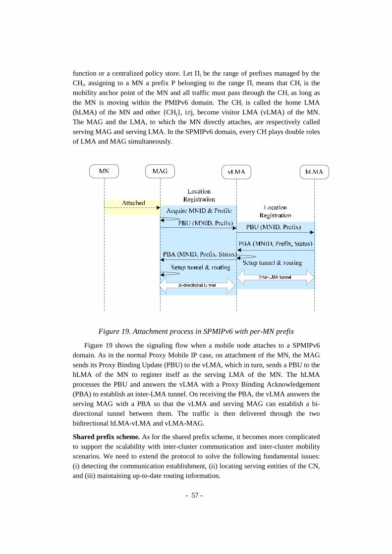
- 57 -
function or a centralized policy store. Let Πi be the range of prefixes managed by the CHi, assigning to a MN a prefix P belonging to the range Πi means that CHi is the mobility anchor point of the MN and all traffic must pass through the CHi as long as the MN is moving within the PMIPv6 domain. The CHi is called the home LMA (hLMA) of the MN and other {CHj}, i ≠j, become visitor LMA (vLMA) of the MN. The MAG and the LMA, to which the MN directly attaches, are respectively called serving MAG and serving LMA. In the SPMIPv6 domain, every CH plays double roles of LMA and MAG simultaneously.
Figure 19. Attachment process in SPMIPv6 with per-MN prefix
Figure 19 shows the signaling flow when a mobile node attaches to a SPMIPv6 domain. As in the normal Proxy Mobile IP case, on attachment of the MN, the MAG sends its Proxy Binding Update (PBU) to the vLMA, which in turn, sends a PBU to the hLMA of the MN to register itself as the serving LMA of the MN. The hLMA processes the PBU and answers the vLMA with a Proxy Binding Acknowledgement (PBA) to establish an inter-LMA tunnel. On receiving the PBA, the vLMA answers the serving MAG with a PBA so that the vLMA and serving MAG can establish a bi-directional tunnel between them. The traffic is then delivered through the two bidirectional hLMA-vLMA and vLMA-MAG.
Shared prefix scheme. As for the shared prefix scheme, it becomes more complicated to support the scalability with inter-cluster communication and inter-cluster mobility scenarios. We need to extend the protocol to solve the following fundamental issues: (i) detecting the communication establishment, (ii) locating serving entities of the CN, and (iii) maintaining up-to-date routing information.

- 58 -
4.2. Detecting Communication Establishment We define the communication in this work as the exchange of traffic between two
nodes. By inspecting ICMPv6 messages or data traffic, this process determines the scope of communications, i.e. intra-cluster communication or inter-cluster communication, and provides triggers for route setup in case of inter-communication or Route Optimization.
When the shared prefix approach is used, both nodes use the same network prefix. MNs in the domain consider each other as on-link and therefore trigger Neighbor Unreachability Detection (NUD) [43] during their communication establishment. The MN sends a Neighbor Solicitation (NS) message to resolve the IP address of the CN to the MAC address of the CN. All NS messages for Address Resolution are inspected by the edge entities - the MAG or the LMA. As the CN address is stored in the target field, the serving entities can look for the target in their binding cache to check if they are also the serving entities for the CN.
Monitoring the traffic could be a complement mechanism. In such deployment, a connection tracking module must be installed on MAGs. Netfilter subsystem can provide this feature with the ip_conntrack module.
4.3. Locating the Serving Entities Let MAGMN and LMAMN respectively denote the serving MAG and the serving
LMA of the MN. Also let MAGCN and LMACN denote the serving MAG and the serving LMA of the CN respectively.
For an arbitrary ad-hoc topology, when establishing the communication between an MN and a CN belonging to different clusters, LMAMN needs to know LMACN, and eventually MAGCN. This location issue is expressed as the problem of mapping a CN address into its serving LMA address or its serving MAG address. Later, we will discover in Chapter 4 the same problem which arises when establishing the communication with route optimization between an MN and a CN whereas MAGMN needs to know MAGCN.
To resolve this mapping problem in a distributed environment, we propose a new couple of messages: Proxy Binding Request (PBReq) and Proxy Binding Response (PBRes). Five new options are also defined: four options named generally Serving Entity Address options, and Source MN Address option.
4.4. Maintaining Routing Information When the MN moves from one cluster to a new cluster, the old LMA may not be
aware about the changes, the new LMA can advertise a PBRes message to All-LMA multicast address. This message helps the old LMA to activate the Location Deregistration procedure if necessary, and helps other LMAs to maintain up-to-date routing information to keep on-going session.

- 59 -
4.5. Message Structure
Figure 20. Proxy Binding Request (PBReq) Message
Figure 21. Proxy Binding Response (PBRes) Message
Figure 22. Serving Entity or Source MN Address Options
Figure 20 shows the PBReq message structure with Mobile Header (MH) Type taking the value 8. The official value should be registered at the Internet Assigned Numbers Authority (IANA) [50]. The PBReq with the Location (L) bit is sent by MAGMN to LMAMN to find which MAG is serving the CN in the case of intra-cluster communication. The Link-layer Identifier option and the Home Network Prefix Option are mandatory and used to carry the CN address. The PBReq is also sent by the LMA to All-LMA multicast group in case of inter-cluster communication to find which MAG and which LMA are serving the CN.
Figure 21 shows the PBRes message with the MH Type taking the value 9. It is the

- 60 -
reply to a PBReq and can eventually contain options carrying the MAGCN address and/or the LMACN address. The Location bit (L) signifies the message is an answer to a PBReq locating a CN. The Inter-cluster Mobility Indication bit (I) indicate that the PBRes message is a hint for movement detection in the inter-cluster mobility scenario.
As regards the Serving Entity Address options and the Source MN Address option (see Figure 22), we use five different values of Option Type to classify: Source MN address (0x0B), MAGMN address (0x0C), LMAMN address (0x0D), MAGCN address (0x0E) or LMACN address (0x0F). More information about message structure can be found in the Appendix A.
4.6. Intra-cluster Communication Scenario An MN can communicate with a Correspondent Node (CN) in the same cluster, i.e.
intra-cluster communication. Both Nodes use the same network prefix.
The signaling flow for intra-cluster communication scenario is proposed as in Figure 23. The MN sends an NS (Neighbor Solicitation) message to get the IP address of the CN. The MN’s associated Access Router checks via its CH to find the AR of attachment of the CN: Proxy Binding Request and Proxy Binding Response message exchange. As both MN and CN are registered under the same LMA, the LMA can reply the MAGMN with a PBRes. Once received the answer or on timeout of the PBRes, the MAGMN do the Proxy ARP for the CN. The MAGMN acts then as a proxy for the IP packets transmission as in the base PMIPv6 protocol. The reverse traffic is delivered in a similar way. Through the same bidirectional tunnel
Figure 23. Intra-cluster Communication Establishment

- 61 -
4.7. Intra-cluster Mobility Scenario
Figure 24. Intra-cluster Mobility
As for intra-cluster mobility scenario, Figure 24 shows signaling flow between PMIP6 entities to maintain up-to-date routing information. At any point, the old MAGMN detects that the MN has moved away from its access link, or if it decides to terminate the MN's mobility session, it starts the Location Deregistration procedure by sending a Proxy Binding Update message to the LMA with the lifetime value set to zero. After detecting a new MN on its access link, the new MAGMN must identify the MN and acquire the MN Identifier. If it determines that the network-based mobility management service needs to be offered to the MN, it must send a Proxy Binding Update message to the LMA to start the Location Registration procedure.
Upon accepting this Proxy Binding Update message, the LMA sends a Proxy Binding Acknowledgement message including the MN's home network prefix. It also creates the Binding Cache entry and sets up its endpoint of the bi-directional tunnel to the new MAGMN. The new MAGMN, on receiving the Proxy Binding Acknowledgement message, sets up its endpoint of the bi-directional tunnel to the LMA and also sets up the data path for the MN's traffic. At this point the new MAG will have all the required information for emulating the MN's home link. It sends Router Advertisement messages to the MN on the access link advertising the MN's home network prefix as the hosted on-link-prefix.

- 62 -
4.8. Inter-cluster Communication Scenario The inter-clusters communication establishment is illustrated in Figure 25. Once
the MN triggers an NS to find the CN, MAGMN uses the target field for lookup in its binding cache. If no information is found for that target belonging to the same PMIPv6 domain, i.e. cache missed, the MAGMN assumes that the CN is away from its link and sends a PBReq message to the LMAMN. If the LMAMN does not have any information about the target, it must send a PBReq to All-LMA multicast address. The LMACN, which is serving the CN, will reply with a PBRes carrying at least the LMACN address. Using information provided in the PBRes, the LMAMN can setup a routing entry pointing for a bidirectional tunnel with the LMACN. As a result, a default path traversing LMAs is set up for the communication between MN and CN. The LMAMN then will reply with a PBRes to the MAGMN. The MAGMN will perform Proxy ARP for the CN to update the neighbor cache of the MN. Then the MN can start sending packets to the CN through a chain of three bidirectional tunnels.
Figure 25. Inter-clusters communication establishment
4.9. Inter-cluster Mobility Scenario When the MN moves between two MAGs belonging to two different clusters, the
inter-cluster mobility happens. As the old LMA may not be aware about the changes, the new LMA can send a PBRes message with the bit (I) to All-LMA multicast address. This message helps the old LMA to activate the Location Deregistration procedure if necessary, and helps other LMAs to maintain up-to-date routing information.

- 63 -
5. Numerical Analysis of SPMIPv6 in WMN In this section, we investigate the scalability of SPMIPv6 in WMNs which are able
to dynamically self-organize and self-configure. We use mathematical model inspired from [51][52][53], to investigate the scalability of PMIPv6 and SPMIPv6 in a WMN with consideration of the WMN size, MN density, and average mobile speed. We wish to state that the analysis is approximate and contains simplifying assumptions made for the sake of analytical tractability. However it can provide a macroscopic view of the scalability.
5.1. Assumptions We consider the WMN with hexagonal cell structure, assuming that each cell is
served by an AR. The coverage area of a cluster is also hexagon shaped. For PMIPv6, one LMA can serve the whole WMN, but once SPMIPv6 is introduced, each LMA resides at one CH and serves only its cluster. Each LMA has a limited capacity beyond which the system performance degrades exponentially. Therefore to avoid the overloaded situation, LMAs use access control policy to reject handover attempts causing overload.
Figure 26. Structure of a cluster
The structure of such a cluster is shown in Figure 26. The size of a cluster can be
defined as the number of ARs along the side of the cluster hexagon. Let � denote the size of a cluster, so the number of ARs in a cluster is
�� � 3��� � 1 1
The perimeter of an AR cell is �, so the area of a cell, denoted as , is
�√3
24��
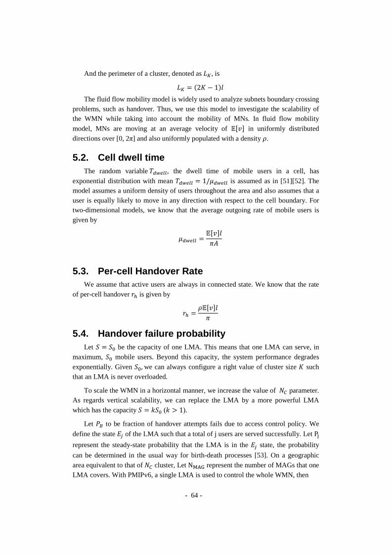
- 64 -
And the perimeter of a cluster, denoted as ��, is
�� � �2� � 1�
The fluid flow mobility model is widely used to analyze subnets boundary crossing problems, such as handover. Thus, we use this model to investigate the scalability of the WMN while taking into account the mobility of MNs. In fluid flow mobility
model, MNs are moving at an average velocity of ���� in uniformly distributed
directions over [0, 2π] and also uniformly populated with a density �.
5.2. Cell dwell time The random variable DEFGHH, the dwell time of mobile users in a cell, has
exponential distribution with mean DEFGHH � 1/IEFGHH is assumed as in [51][52]. The model assumes a uniform density of users throughout the area and also assumes that a user is equally likely to move in any direction with respect to the cell boundary. For two-dimensional models, we know that the average outgoing rate of mobile users is given by
IEFGHH ������
?
5.3. Per-cell Handover Rate We assume that active users are always in connected state. We know that the rate
of per-cell handover J: is given by
J: �������
?
5.4. Handover failure probability Let 1 � 18 be the capacity of one LMA. This means that one LMA can serve, in
maximum, 18 mobile users. Beyond this capacity, the system performance degrades
exponentially. Given 18, we can always configure a right value of cluster size � such that an LMA is never overloaded.
To scale the WMN in a horizontal manner, we increase the value of �9 parameter. As regards vertical scalability, we can replace the LMA by a more powerful LMA
which has the capacity 1 � C18 (C L 1).
Let *+ to be fraction of handover attempts fails due to access control policy. We
define the state MN of the LMA such that a total of j users are served successfully. Let PP
represent the steady-state probability that the LMA is in the MN state, the probability
can be determined in the usual way for birth-death processes [53]. On a geographic
area equivalent to that of �9 cluster, Let NQRS represent the number of MAGs that one LMA covers. With PMIPv6, a single LMA is used to control the whole WMN, then

- 65 -
�-./ � �9��
Otherwise with SPMIPv6, we use multiple LMAs to control the WMN; each LMA resides at the CH and controls only one cluster, then
�-./ � ��
The intensity and the blocking probability *+ are:
��-./J:
IEFGHH� �-./�
*+ � *6 �
0
1!
∑ 4
5!6478
5.5. Numerical Results Numerical results are obtained using MATLAB® R2006b. We realized 500
simulations. For each simulation, we model the increase of the WMN’s geographic
area by increasing the �9 parameter. We model the upgrade of an LMA by increasing
C parameter in a limited range from 1 to 5 because the capacity might be unlimited in theory but is limited in practice. Other system parameters for numerical analysis are taken randomly in the range shown in Table 1.
Table 1. System parameter for numerical analysis
Parameter Values Unit 18 250 nodes �9 {1..20} clusters � {2..3} � {200? .. 400?} m
���� {1..5} m/s � {0.0001 .. 0.0002} nodes/m� C {1..5}
In this part, we analyze the scalability feature of SPMIPv6 with respect to successful per-cell handover probability and successful per-cell handover rate. Figure 27 shows the probability of successful per-cell handover in SPMIPv6 and different cases of PMIPv6. Let *:; denote the probability that a per-cell handover completes successfully. We observe that, when the network is extended horizontally (by
increasing �9 parameter), *:; with only one LMA decreases dramatically; while *:;
with multiple LMAs keeps almost stable. The figure shows five different values of C corresponding to five different capacities of the centralized LMA. This means that we can vertically scale the WMN using a new LMA with larger capacity (by increasing C
parameter). However C is bounded by a limited value because the capacity might be
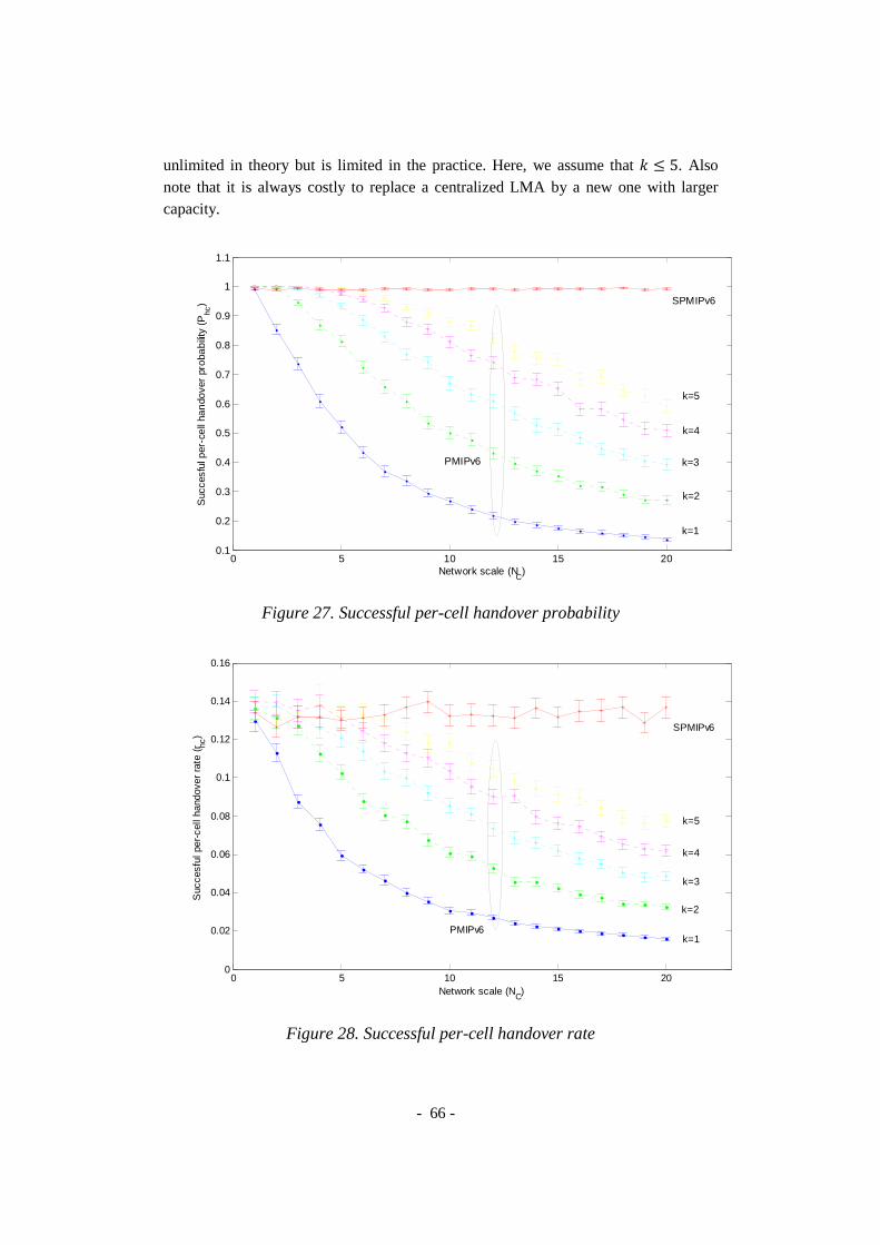
- 66 -
unlimited in theory but is limited in the practice. Here, we assume that C T 5. Also note that it is always costly to replace a centralized LMA by a new one with larger capacity.
Figure 27. Successful per-cell handover probability
Figure 28. Successful per-cell handover rate
0 5 10 15 200.1
0.2
0.3
0.4
0.5
0.6
0.7
0.8
0.9
1
1.1
Network scale (NC
)
Suc
cesf
ul p
er-c
ell
han
dove
r pr
oba
bilit
y (P
hc)
k=3
SPMIPv6
k=4
k=5
k=2
k=1
PMIPv6
0 5 10 15 200
0.02
0.04
0.06
0.08
0.1
0.12
0.14
0.16
Network scale (NC)
Suc
cesf
ul p
er-c
ell h
ando
ver
rate
(r hc
)
SPMIPv6
PMIPv6k=1
k=2
k=3
k=4
k=5

- 67 -
With the fluid flow mobility model, the rate at which per-cell handovers complete
is:
J:; � J:�1 � *+ � J:*:;
Figure 28 shows the successful per-cell handover rate when the network scale varies. Note that this rate depends on the scale of the network and also on the average velocity of MNs. When the network scale increases gradually, SPMIPv6 out performs PMIPv6 as no handover is rejected.
6. Conclusion We have extended PMIPv6 to provide scalability for network-based mobility
management in large wireless networks which are organized as a cluster-based architecture. We specially address the spontaneous wireless mesh network of which the topology is arbitrary and can be dynamically created and changed. Our framework, called Scalable Proxy Mobile IPv6 (SPMIPv6), can support mobility in large scale networks to MNs having standard IPv6 stack without any support from MNs. Applying SPMIPv6 to spontaneous wireless mesh networks can make them a promising solution for ubiquitous Internet access and a wide range of applications, as Public Safety and emergency communications.
The proposed SPMIPv6 extension provides the inter-LMAs interaction which allows increasing the size of the PMIPv6 domain horizontally by adding new clusters gradually. Furthermore, it also supports the share prefix model and provides a mechanism to locate serving entities of a registered MN which will be beneficial for supporting Route Optimization and QoS in later research. Different for intra-cluster and inter-cluster scenarios have been identified and described to explain the detail behavior of the proposed SPMIPv6.
We have evaluated the scalability our SPMIPv6 in a WMN context. A mathematical model has been used to investigate the scalability of the framework with consideration of the WMN size, MN density, and average mobile speed. The metrics, used to reflect the scalability, are the probability of successful per-cell handover and the successful per-cell handover rate. These metrics have been calculated and compared between PMIPv6 and SPMIPv6. Numerical results show that SPMIPv6 provides a mechanism for inter LMAs interactions which can horizontally and gradually scale the WMN. This approach is less expensive than replacing the centralized LMA and avoids the single point of failure problem in PMIPv6. In Chapter 5, we will implement and experiment the SPMIPv6 framework in a virtual IPv6 WMN testbed and provide qualitative and quantitative results to prove the correctness and the advantages of our framework.


- 69 -
CHAPTER 4 - ON THE ROUTE OPTIMIZATION & MOVEMENT DETECTION IN SPMIPV6
In this chapter, we discuss on challenges and possibilities of Route Optimization
(RO) for PMIPv6. We propose an extension for RO support in SPMIPv6 and then describe in detail the proposed design with respect to different scenarios in large scale spontaneous wireless mesh network. Our design provides, at the same time, RO and scalability features. The benefits of RO and its impact on TCP traffic are separately evaluated in the Chapter 5. Later, we investigate different possibilities of movement detection in PMIPv6, and then introduce an enhanced IP-Layer network-based movement detection mechanism to support heterogeneous access technologies in both SPMIPv6 and PMIPv6.
1. Route Optimization Extension for SPMIPv6
1.1. Problem Statement The triangle route problem has been stated in the Mobile IP protocol [22]. Packets
that are sent by a CN to an MN, which is away from home, are routed first to the MN’s HA and then tunneled to the MN’s CoA. However, packets sent by the MN are routed directly to the CN, thus forming a triangle. This can lead to a suboptimal path between the two peers. To establish a more direct communication path, the MN can exchange signaling with a MIPv6 enabled Correspondent Node (CN). The CN learns about the location of the MN and both nodes can exchange traffic using a direct path, bypassing the HA. This optimized routing is potentially more efficient in terms of delay and resource consumption than is triangle routing, because, in general, the packets will have to traverse fewer links on their way to their destination.
In PMIPv6, just like in MIPv6, the default data path between two communication peers may be suboptimal due to the fact that the packet must traverse through the LMA. RO Communication in PMIPv6 focus on data exchange between
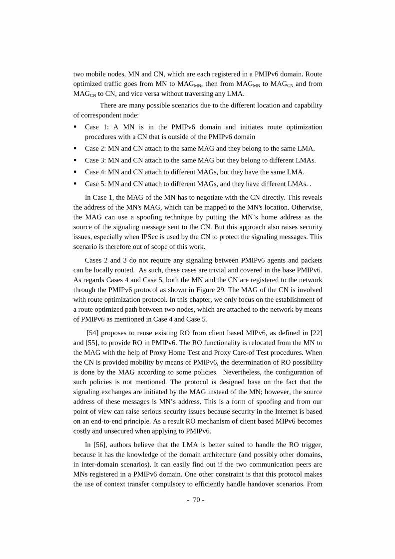
- 70 -
two mobile nodes, MN and CN, which are each registered in a PMIPv6 domain. Route optimized traffic goes from MN to MAGMN, then from MAGMN to MAGCN and from MAGCN to CN, and vice versa without traversing any LMA.
There are many possible scenarios due to the different location and capability of correspondent node:
� Case 1: A MN is in the PMIPv6 domain and initiates route optimization procedures with a CN that is outside of the PMIPv6 domain
� Case 2: MN and CN attach to the same MAG and they belong to the same LMA.
� Case 3: MN and CN attach to the same MAG but they belong to different LMAs.
� Case 4: MN and CN attach to different MAGs, but they have the same LMA.
� Case 5: MN and CN attach to different MAGs, and they have different LMAs. .
In Case 1, the MAG of the MN has to negotiate with the CN directly. This reveals the address of the MN's MAG, which can be mapped to the MN's location. Otherwise, the MAG can use a spoofing technique by putting the MN’s home address as the source of the signaling message sent to the CN. But this approach also raises security issues, especially when IPSec is used by the CN to protect the signaling messages. This scenario is therefore out of scope of this work.
Cases 2 and 3 do not require any signaling between PMIPv6 agents and packets can be locally routed. As such, these cases are trivial and covered in the base PMIPv6. As regards Cases 4 and Case 5, both the MN and the CN are registered to the network through the PMIPv6 protocol as shown in Figure 29. The MAG of the CN is involved with route optimization protocol. In this chapter, we only focus on the establishment of a route optimized path between two nodes, which are attached to the network by means of PMIPv6 as mentioned in Case 4 and Case 5.
[54] proposes to reuse existing RO from client based MIPv6, as defined in [22] and [55], to provide RO in PMIPv6. The RO functionality is relocated from the MN to the MAG with the help of Proxy Home Test and Proxy Care-of Test procedures. When the CN is provided mobility by means of PMIPv6, the determination of RO possibility is done by the MAG according to some policies. Nevertheless, the configuration of such policies is not mentioned. The protocol is designed base on the fact that the signaling exchanges are initiated by the MAG instead of the MN; however, the source address of these messages is MN’s address. This is a form of spoofing and from our point of view can raise serious security issues because security in the Internet is based on an end-to-end principle. As a result RO mechanism of client based MIPv6 becomes costly and unsecured when applying to PMIPv6.
In [56], authors believe that the LMA is better suited to handle the RO trigger, because it has the knowledge of the domain architecture (and possibly other domains, in inter-domain scenarios). It can easily find out if the two communication peers are MNs registered in a PMIPv6 domain. One other constraint is that this protocol makes the use of context transfer compulsory to efficiently handle handover scenarios. From

- 71 -
our point of view, letting the LMA make the RO decision is a good choice but delegate the RO trigger detection to LMA will degrade the scalability of the PMIPv6 domain.
Figure 29. Route Optimization Support for SPMIPv6
Both of these solutions have shortcomings. To introduce RO into SPMIPv6, we design a solution with specialized signaling defined between MAGs, or between LMAs and MAGs to setup and maintain route optimization states for MN and CN. Then a MN, attached to an AR, can communicate with a CN in the SPMIPv6 domain in an optimal way; the traffic can be routed from the AR to the relay router, reaching the other AR without passing through CHs (see Figure 29). The solid lines show the suboptimal route in case of intra-cluster communication and inter-cluster communication. The dashed lines show optimal routes for intra-cluster communication and inter-cluster communication. Our approach is similar as [56] and [57], but more complete and scalable. We emphasize that the RO trigger should be handled by the LMA but the RO trigger must be originated at the MAG to ensure the scalability of the SPMIPv6 domain.
1.2. Conceptual Architecture To coordinate the set up and maintenance of the route optimized path efficiently, a
Route Optimization Controller (RO controller) function is assigned to LMAs. During the set up of the route optimized path, one LMA is dynamically selected as active RO controller. In case the two MNs are registered with different LMAs, only one LMA, which has the active RO controller function assigned for the associated route optimized path, will coordinate the maintenance of the RO path and the establishment of the RO states on the MAG(s) upon handover. We reuse the terms introduced by [57] in the
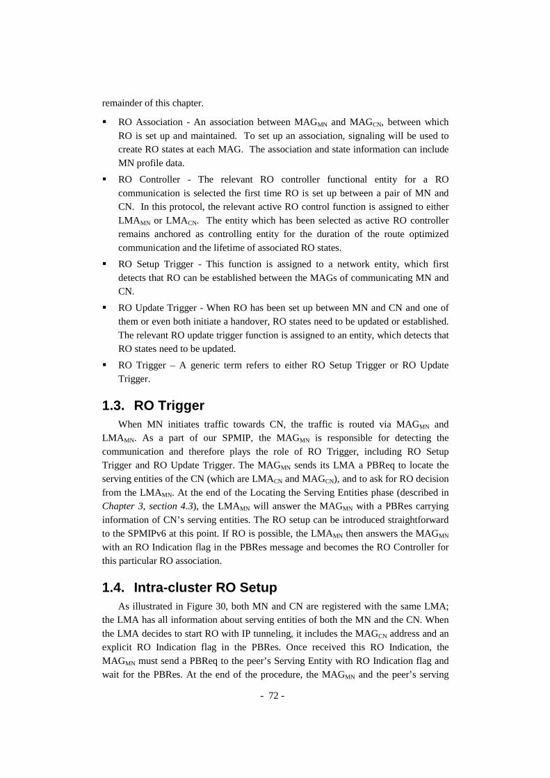
- 72 -
remainder of this chapter.
� RO Association - An association between MAGMN and MAGCN, between which RO is set up and maintained. To set up an association, signaling will be used to create RO states at each MAG. The association and state information can include MN profile data.
� RO Controller - The relevant RO controller functional entity for a RO communication is selected the first time RO is set up between a pair of MN and CN. In this protocol, the relevant active RO control function is assigned to either LMA MN or LMACN. The entity which has been selected as active RO controller remains anchored as controlling entity for the duration of the route optimized communication and the lifetime of associated RO states.
� RO Setup Trigger - This function is assigned to a network entity, which first detects that RO can be established between the MAGs of communicating MN and CN.
� RO Update Trigger - When RO has been set up between MN and CN and one of them or even both initiate a handover, RO states need to be updated or established. The relevant RO update trigger function is assigned to an entity, which detects that RO states need to be updated.
� RO Trigger – A generic term refers to either RO Setup Trigger or RO Update Trigger.
1.3. RO Trigger When MN initiates traffic towards CN, the traffic is routed via MAGMN and
LMA MN. As a part of our SPMIP, the MAGMN is responsible for detecting the communication and therefore plays the role of RO Trigger, including RO Setup Trigger and RO Update Trigger. The MAGMN sends its LMA a PBReq to locate the serving entities of the CN (which are LMACN and MAGCN), and to ask for RO decision from the LMAMN. At the end of the Locating the Serving Entities phase (described in Chapter 3, section 4.3), the LMAMN will answer the MAGMN with a PBRes carrying information of CN’s serving entities. The RO setup can be introduced straightforward to the SPMIPv6 at this point. If RO is possible, the LMAMN then answers the MAGMN with an RO Indication flag in the PBRes message and becomes the RO Controller for this particular RO association.
1.4. Intra-cluster RO Setup As illustrated in Figure 30, both MN and CN are registered with the same LMA;
the LMA has all information about serving entities of both the MN and the CN. When the LMA decides to start RO with IP tunneling, it includes the MAGCN address and an explicit RO Indication flag in the PBRes. Once received this RO Indication, the MAGMN must send a PBReq to the peer’s Serving Entity with RO Indication flag and wait for the PBRes. At the end of the procedure, the MAGMN and the peer’s serving

- 73 -
entity establish a bidirectional tunnel and update routing entry to forward the traffic through the optimized bidirectional tunnel. The traffic is then forwarded in an optimized way directly between MAGs, e.g. MAGMN-MAGCN. Once the path is set up, the traffic between the MN and the CN can be delivered directly through the optimized bidirectional tunnel. The RO Association soft state of the communication is then maintained in the RO cache of all serving MAGs and LMA during the movement of MN and CN within the SPMIPv6 domain.
Figure 30. Route Optimization Setup
1.5. Inter-cluster RO Setup Figure 31 shows the complete process for Inter-cluster RO setup. We still assume
that MN initiates traffic with CN. As a part of our SPMIP, the MAGMN is responsible for detecting the communication and therefore plays the role of RO Trigger. The MAGMN sends the LMAMN a PBReq to locate the serving entities of the CN and to ask for RO decision from the LMAMN. At the end of the Locating the Serving Entities phase, the LMAMN and MAGMN have all necessary information to setup RO. The RO Indication bit (R) in the PBRes indicates to MAGMN that RO communication is possible between MN and CN.

- 74 -
Figure 31. Inter-cluster Route Optimization Setup
Subsequently, the MAGMN sends a PBReq with RO Indication to the peer’s serving entity, e.g. MAGCN. At the end of the RO Setup procedure, the MAGMN and the peer’s serving entity establish a bidirectional tunnel and update routing entry to forward the traffic through the optimized bidirectional tunnel. The traffic is then forwarded in an optimized way directly between MAGs, i.e. MAGMN-MAGCN. The RO Association soft state of the communication is then maintained in all serving MAGs and LMAs’ RO cache also during MN and CN’s movements within the SPMIPv6 domain.
Note that the traffic can also be forwarded in an optimized way through only one of the LMAs, e.g. MAGMN-LMA MN-MAGCN or MAGMN-LMA CN-MAGCN. This case is only near optimal, however reduces the RO maintenance complexity.
1.6. RO Maintenance MN’s mobility between different MAGs affects the RO associations. In the case of
intra-cluster mobility, any Location Deregistration event will cause the cancellation of the RO communication in both directions. Whenever binding cache entry of MN is

- 75 -
modified at the LMAMN, as the RO Controller, LMAMN must inform involved MAGCN about the changes by using an unsolicited PBRes to redirect the related traffic through the default route in the meantime the new RO is again established.
In the case of inter-cluster mobility, as the previous LMAMN may not be aware about the changes, the new LMAMN can send a PBRes message to All-LMA multicast address. This message helps the old LMAMN to activate the Location Deregistration procedure if necessary, and helps other LMAs to maintain up-to-date routing information for on-going sessions.
1.7. Message Structure
Figure 32. Proxy Binding Request Message
Figure 33. Proxy Binding Response Message
Figure 32 and Figure 33 show extended PBReq and PBRes messages, which are previously presented in Chapter 3, for RO. When the RO Indication (R) bit is set, the message is used to request the peer’s serving entity to setup the optimized bidirectional tunnel. The LMA also set this bit to indicate the MAG that RO is possible. To identify and maintain the RO cache entry, the MN address within the Source MN Address option is combined with the CN address as the search key.

- 76 -
2. Movement Detection for Heterogeneity
2.1. Problem Statement Another important aspect of any mobility protocol is the movement detection.
Despite of a lot of publications on Network-based Mobility Management in general and PMIPv6 in particular, the movement detection has usually been ignored or assumed to be the link-layer based approach. Most of experimental results are based on wireline testbed or IEEE 802.11 testbed. This somehow limits the real capacity of PMIPv6 which is designed for vertical handover between heterogeneous access technologies, especially between 3GPP and non-3GPP networks.
A movement detection mechanism in PMIPv6 must rely on different events as a hint for triggering the Location Registration procedure and the Location Deregistration procedure. The hints for movement detection can be the Link-Layer Events, Traffic Monitoring Events or DNAv6 [42]. Table 2 compares advantages and the drawbacks of different approaches:
Table 2. Comparison of Movement Detection Approaches
Hints Advantages Drawbacks
Traffic Monitoring Events
Independent from access technologies.
Processing overhead at MAGs.
Link-Layer Event Accurate and Rapid. Dependent on access technologies.
DNAv6 Independent from access technologies.
Initialized by MN and dependent on MN
� A traffic monitoring based mechanism only works properly when there is uplink traffic from the MN to the network. The mechanism can be independent from the access technology but causes processing overhead at MAGs as they must inspect every packet sent on the link.
� A link-layer based mechanism can be accurate and rapid. However, in a heterogeneous environment, it depends on particular access technologies and requires a lot of modifications either on the network side or on the terminal side; therefore the deployment becomes difficult.
� DNAv6 also provides an IP-layer movement detection independent from access technology. DNAv6 uses the fact that the MN decides to attach to the new MAG and sends ICMPv6 [58] message, e.g. Router Solicitation (RS), when it moves to a new link. The mechanism depends on the way the MN itself detects link changes and on its layer-2 device driver.
- 77 -
As mentioned in Chapter 3, in our cluster-based architecture for SPMIPv6, ARs can control heterogeneous radio access technologies; meanwhile all described movement detection solutions have drawbacks. We propose here an enhanced network-
based IP-layer movement detection as a short-term solution for heterogeneous networks. The advantage of our proposal is that it doesn’t require any special software on the MN and is independent from the access technologies. Furthermore, by enhanced, we mean that the dependence on the device driver of the MN is eliminated. This will help to promote PMIPv6 in practice gradually in short terms and later to optimize PMIPv6 with link-layer specific movement detection mechanism in long terms.
2.2. Enhanced IP-Layer Movement Detection
2.2.1. Assumptions In the base PMIPv6, the MN maintains an IP address that is unchanged within the
PMIPv6 domain and is used for communications. This address is a global routable IP address and is referred in this thesis as PMIPv6 address.
In our proposal, each MAG broadcasts Router Advertisements (RAs) containing two prefixes: (i) a global prefix P which is assigned to each MN (per-MN prefix) or is shared by all MNs (multi-link subnet with shared prefix) and (ii) a site-scope prefix P*. The global PMIPv6 address is configured from the global prefix P while the temporary site-scope IP address is configured from the site-scope prefix P*.
Whenever the MN moves to a new link, it configures a new temporary address and deletes the previous temporary address when its preferred lifetime is expired. We would like to emphasize that this temporary address is not used for communications between MN and CN. Therefore the handover latency will not be affected by the result and the latency of the temporary address’s auto-configuration process. The NS message in Duplicate Address Detection (DAD) process for the new temporary address is used as a hint for the network attachment detection. The following assumptions are taken into account.
Assumption 1: the MAG could extract the MNID, e.g. the MAC address or public key, from any ICMPv6 messages sent by the MN, e.g. Neighbor Solicitation (NS), Router Solicitation (RS), and Neighbor Advertisement (NA). Besides, there exists a bidirectional conversion between the MNID and the PMIPv6 address. Given a PMIPv6 address, we can infer the MNID and vice versa.
Assumption 2: If multiple addresses are active for the same interface, depending on the destination address, the source address of the communication is selected according to the Source Address Selection algorithm [59].
The first assumption allows the MAGs to detect the hints for network attachment

- 78 -
of a MN by inspecting ICMPv6 messages sent by the MN. The second assumption ensures that the MN always prefer the PMIPv6 address for communications even when multiple addresses co-exist and therefore global prefix P and temporary site-scope prefix P* could be broadcasted by the MAG on the same link.
2.2.2. Algorithm Descriptions With the above precondition, each MN will have two IPv6 addresses: one is
PMIPv6 address, which is a global IPv6 address and is unchanged within the PMIPv6 domain; another is the temporary address, which is a site-scope IPv6 address and is reconfigured whenever the MN moves from the old MAG to a new MAG. Here is the event-driven pseudo code:
Thanks to the temporary site-scope prefix P* in Router Advertisement messages, sent periodically by the MAG, the MN configures temporary site-scope address and activate DAD procedure by sending an NS message. This message will be used as a hint for the new MAG to verify if the MN is really attached to it. The new MAG activates the Neighbor Unreachability Detection (NUD) procedure by sending NS for address resolution with the target set to PMIPv6 Address. It also creates a temporary binding cache entry for the MN with a short life time and waits for the NA. If the MN has really moved inside the coverage of the new MAG and associate with the new MAG at the link layer, it must be able to answer this NS with an NA as a default behavior of Neighbor Discovery for IP Version 6 (NDPv6) [43]. The NA message, with the PMIPv6 address as the target, confirms the attachment of the MN and activates the Location Registration procedure.

- 79 -
Algorithm Enhanced IP-Layer Movement Detection (this algorithm runs on the MAG, doesn’t require any special software on the MN and is independent from the access technologies).
1
2
3
4
5
6
7
8
9
10
11
12
13
14
15
16
17
18
19
20
21
22
23
24
25
26
27
28
29
30
31
32
33
34
35
36
37
on receiving an NS(target) for DAD
begin
Extract target
Compute MNID = get_MNID(NS)
Compute PMIPv6 address = get_Address(MNID)
if there is no PMIP binding entry for the MNID
begin
if get_Prefix(target) = P*
begin
Send NS (with target= PMIPv6 address) for ARP
Create a "temporary" PMIP binding entry with a lifetime T*
end
else if get_Prefix(target) = P
output Attachment Event (MNID)
end
end
on receiving a NA(target) which replies the NS for ARP
begin
Extract target
Compute MNID=get_MNID(NA)
if there exists a "temporary" PMIP binding entry for the MNID
if get_Address(MNID) = target
output Attachment Event (MNID)
end
on Attachment Event (MNID)
begin
Start Location Registration Procedure (MNID)
if there exists a "temporary" PMIP binding entry for the MNID
Set the PMIP binding entry to "permanent"
else if there is no PMIP binding entry for the MNID
Create a "permanent" PMIP binding entry
end
on T* expired
Delete the associated "temporary" PMIP binding entry

- 80 -
Figure 34. Example of Enhanced Network-based IP-Layer Movement Detection
Figure 34 shows a sequence diagram of a typical handover scenario, with enhanced network-based IP-layer movement detection, in which the MN first comes to the PMIPv6 domain (using a shared prefix) and attaches to the MAG1. Later, the MN moves away from MAG1 and attaches to the MAG2.
3. Applications of SPMIPv6 with RO Support In [60] we presented, as an example, the application of the proposed SPMIPv6
with RO support in WMN to cover the important research area of Public Safety communications and its application to emergency mobile communications.
When a large scale disaster strikes, first responders are sent to the site immediately. Once the most pressing needs of the disaster are addressed, the next step

- 81 -
is to establish a command and control center. To accommodate this need, a communication infrastructure is required to provide decision makers with data and information from the site to receive digital maps, data and feedback from personnel in the field in a timely manner. Also, it should be able to provide a reliable connection with enough resources for a distributed command and control center. The communication infrastructure needs to be reliable and interoperable with the existing responder organizations’ devices in a distributed system. Additionally, it needs to be easily configurable and quickly deployable at low cost. The system should be designed in a modular fashion that is easily upgradeable with the technology evolvement without the need to replace the entire system. This leads to an economic deployment solution which is affordable for different public and private agencies. Furthermore, it is desirable to provision redundancy for an effective network management based on the trade-off between reliability and cost.
Mesh network infrastructure fulfils well this application domain’s specific requirements, but to assess its complete suitability to Public Safety and disaster recovery applications, it is necessary to include mobility support and scalability requirements to WMNs.
As regards mobility, in order to help emergency personnel to concentrate on the tasks, the emergency network must be mobile, deployed easily and fast with little human maintenance. Therefore, devices must be capable of automatically organizing into a network. Procedures involved in self-organization include device discovery, connection establishment, scheduling, address allocation, routing, and topology management. Public Safety users must have access to constant communication while traveling at reasonable speeds. The mobility requirement includes the ability to roam between different networks, potentially operated by different agencies and jurisdictions. WMNs still need a mobility management mechanism for transparently and seamlessly achieving handover during mobile node movements.
On the other side, disasters may affect a locality or could spread or cascade to affect larger areas, thus horizontal and vertical scalability requirements are of extreme importance for Public Safety communication systems. Suboptimal deployment and a frequently changing environment challenge network functionality. Therefore, the network must be able to report environment changes for proper management or be self-manageable to avoid service disruption. WMNs have to take into account the degradation of the throughput when increasing the number of hops in the end-to-end communication and the difficulties of managing the changing in the network topology.
The proposed SPMIPv6 with RO for heterogeneous spontaneous WMNs resolves many important issues, like mobility and scalability with unmodified mobile nodes, which arises when designing a robust communication infrastructure with applications for emergency response situations. In order to provide a better understanding on how the proposed scenario can approach the most common emergency situations, we take into consideration the following practical scenarios:

- 82 -
� The first scenario represents the case in which a natural disaster occurs in a populated area, causing lives in danger and disruption of the complete network infrastructure. Different governmental agencies, like fire brigades, law enforcement agency and emergency medical teams, need a new rapidly deployable infrastructure suitable for emergency operations. As shown in Figure 35, the WMN with mobility and scalability features can be the common core network used for interconnecting mobile end user networks. Each local wireless network is free to use a different technology depending on the agency and unmodified mobile terminals. It relies upon the high scalable WMN architecture for communications inside the disaster area with other rescue teams. For communications outside the crisis site, one or more gateways, i.e. satellite gateways, can be connected to the WMN in order to provide connectivity with the headquarters for rescue coordination commands.
� The second scenario represents the case in which several buildings are burning in a limited area, lives are in danger inside the buildings and the fire has disrupted the network in that area. Fire brigades and medical teams need an extended coverage of the fixed and untouched network in order to communicate and follow rescue commands inside the affected area. As illustrated in Figure 36, the proposed extended PMIPv6 can be used to provide such coverage extension, deploying from the gateway attached to the fixed infrastructure a cluster head and mobile routers in order to bring connectivity to mobile rescue teams.
Figure 35. Extended PMIPv6 for post-disaster network deployment

- 83 -
Figure 36. Extended PMIPv6 for coverage extension of fixed infrastructure
4. Conclusion We have considered route optimization support for PMIPv6 in general and applied
it in SPMIPv6 in particular with respect to different possible RO cases. We have taken interest only in RO cases where both MN and CN are registered to the network by means of SPMIPv6. Our design provides, at the same time, RO and scalability features.
We have proposed an enhanced network-based IP-layer movement detection for heterogeneous networks. The advantage of our proposal is that it doesn’t require any special software on the MN and is independent from the access technologies. The proposed mechanism is independent from the link-layer and accepts all existing link-layer device drivers. All the intelligence is immigrated to the MAG to support a widest range of MN. It will help to promote PMIPv6 in practice gradually in short terms and later to optimize PMIPv6 with link-layer specific movement detection mechanism in long terms. In Chapter 5, it will be used, with a simulated IEEE 802.11 MAC layer, for the evaluation of PMIP extensions for Scalability and Route Optimization in a virtual testbed.

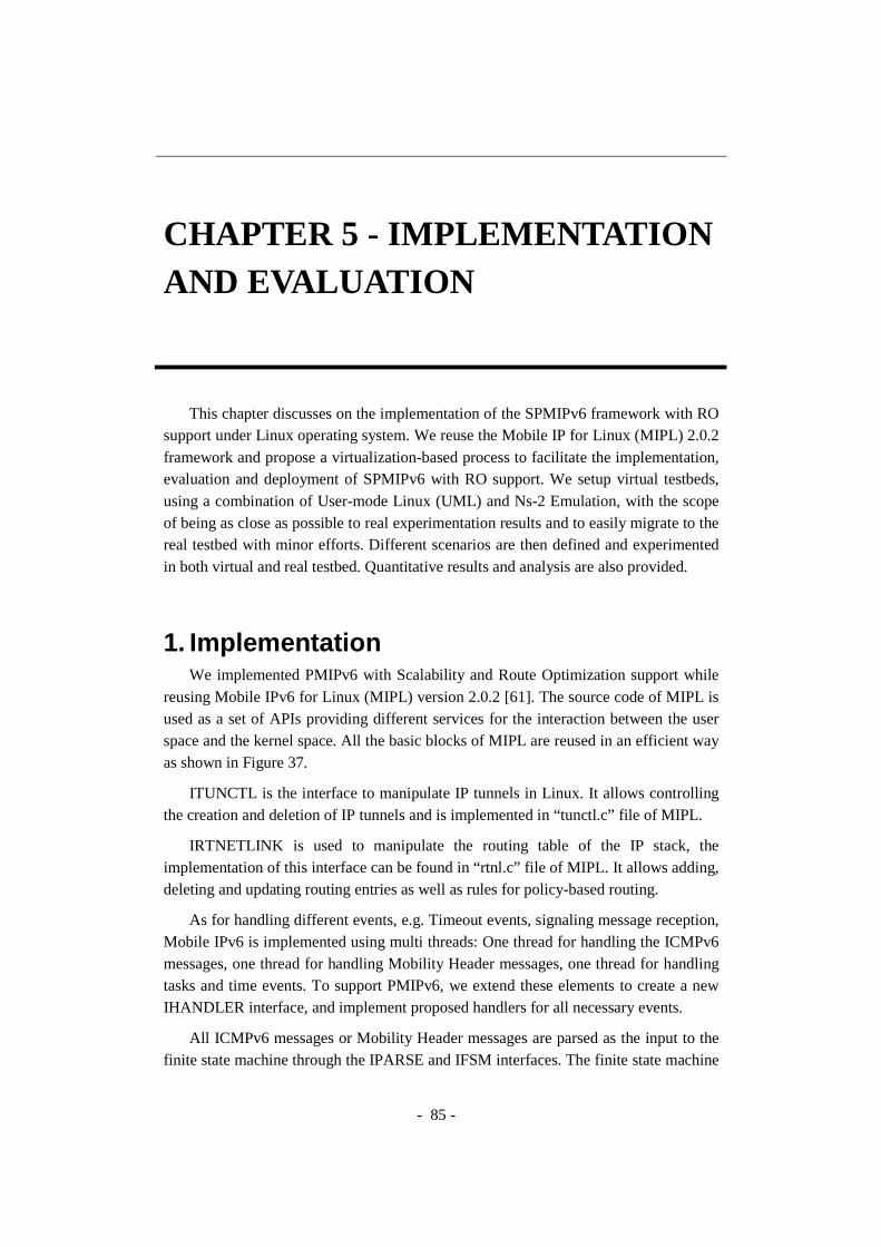
- 85 -
CHAPTER 5 - IMPLEMENTATION AND EVALUATION
This chapter discusses on the implementation of the SPMIPv6 framework with RO support under Linux operating system. We reuse the Mobile IP for Linux (MIPL) 2.0.2 framework and propose a virtualization-based process to facilitate the implementation, evaluation and deployment of SPMIPv6 with RO support. We setup virtual testbeds, using a combination of User-mode Linux (UML) and Ns-2 Emulation, with the scope of being as close as possible to real experimentation results and to easily migrate to the real testbed with minor efforts. Different scenarios are then defined and experimented in both virtual and real testbed. Quantitative results and analysis are also provided.
1. Implementation We implemented PMIPv6 with Scalability and Route Optimization support while
reusing Mobile IPv6 for Linux (MIPL) version 2.0.2 [61]. The source code of MIPL is used as a set of APIs providing different services for the interaction between the user space and the kernel space. All the basic blocks of MIPL are reused in an efficient way as shown in Figure 37.
ITUNCTL is the interface to manipulate IP tunnels in Linux. It allows controlling the creation and deletion of IP tunnels and is implemented in “tunctl.c” file of MIPL.
IRTNETLINK is used to manipulate the routing table of the IP stack, the implementation of this interface can be found in “rtnl.c” file of MIPL. It allows adding, deleting and updating routing entries as well as rules for policy-based routing.
As for handling different events, e.g. Timeout events, signaling message reception, Mobile IPv6 is implemented using multi threads: One thread for handling the ICMPv6 messages, one thread for handling Mobility Header messages, one thread for handling tasks and time events. To support PMIPv6, we extend these elements to create a new IHANDLER interface, and implement proposed handlers for all necessary events.
All ICMPv6 messages or Mobility Header messages are parsed as the input to the finite state machine through the IPARSE and IFSM interfaces. The finite state machine

- 86 -
is the heart of the system and makes appropriate decisions and controls all other elements to provide a correct predefined protocol behavior.
We define and implement the ICACHE interface for maintaining the PMIPv6 binding cache, and IROCACHE interface for maintaining the RO associations. These interfaces provide different important services such as: allocate, add, modify, get, delete, lock, release, etc.
As PMIPv6 implementation is built on top of MIPL, it could be later integrated in MIPL easily and grows in line with the standards as well as MIPL source code.
Figure 37. PMIPv6 Software Architecture
The process for development and evaluation of PMIPv6 with Scalability and Route Optimization support are described in the following sections.
2. Virtualization-based Development Process Future Mobile Internet has to cope with mobility management and multi-homing
for an Always Best Connected vision. However working in such a mobility and multi-homing environment costs a lot in terms of money, time and efforts; a new process based on virtualization should be considered to reduce these costs.
This section describes in details the User Mode Linux (UML) [62] approach that can be adapted easily to different purposes: virtual networking, distributed application development, driver or kernel development. A practical and unified virtualization-based process is proposed for developing the future Mobile Internet protocols in Linux environment using UML and Mobile IPv6 for Linux (MIPL). The process is then
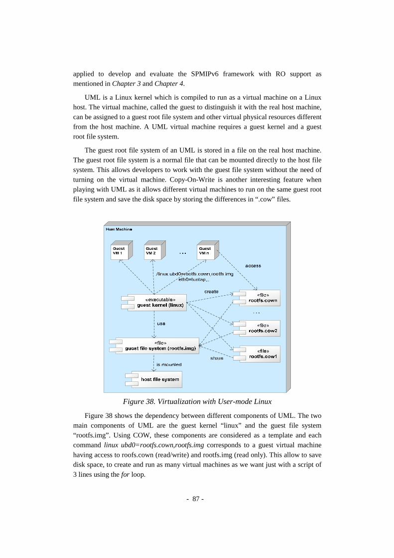
- 87 -
applied to develop and evaluate the SPMIPv6 framework with RO support as mentioned in Chapter 3 and Chapter 4.
UML is a Linux kernel which is compiled to run as a virtual machine on a Linux host. The virtual machine, called the guest to distinguish it with the real host machine, can be assigned to a guest root file system and other virtual physical resources different from the host machine. A UML virtual machine requires a guest kernel and a guest root file system.
The guest root file system of an UML is stored in a file on the real host machine. The guest root file system is a normal file that can be mounted directly to the host file system. This allows developers to work with the guest file system without the need of turning on the virtual machine. Copy-On-Write is another interesting feature when playing with UML as it allows different virtual machines to run on the same guest root file system and save the disk space by storing the differences in “.cow” files.
Figure 38. Virtualization with User-mode Linux
Figure 38 shows the dependency between different components of UML. The two main components of UML are the guest kernel “linux” and the guest file system “rootfs.img”. Using COW, these components are considered as a template and each command linux ubd0=rootfs.cown,rootfs.img corresponds to a guest virtual machine having access to roofs.cown (read/write) and rootfs.img (read only). This allow to save disk space, to create and run as many virtual machines as we want just with a script of 3 lines using the for loop.

- 88 -
Figure 39. Unified Development Process for Mobile IP in UML/real testbed
The Figure 39 shows a practical and unified process for developing Mobile IPv6 and its extensions that can function well in both virtual and real testbeds. This process reduces the cost of equipments but also the time and effort for developing, debugging, and evaluating. The process stays the same if you want to develop a new kernel module.

- 89 -
Starting from the Linux kernel source, we apply the UML kernel patch to add a new architecture for UML (ARCH=um) to the Linux kernel source tree. Recently UML has been integrated into the mainline Linux kernel and no patch is needed anymore. The developer can work on this kernel source for both real machine and virtual machines. To develop Mobile IP, we apply MIPL patch if required, add new functionalities to MIPL user space, and compile it. If we want to create a real test bed, just compile this Linux kernel source in the x86/sparc/mips architecture; otherwise, we create a guest kernel running in UML architecture by compiling the kernel source with ‘ARCH=um’ option in the make command line.
3. Virtual Wireless Networking Environment Figure 40 shows a combination of User-mode Linux and The Ns-2 emulation for
creating the virtual wireless networking environment. The Ns-2 emulation feature is used to emulate the wireless environment. It can grab packets from a virtual machine with real IPv6 stack, pass them through a simulated wireless network, and then inject them into the destination virtual machine.
We extend the Ns-2 Emulation [63], allowing the mapping of the virtual machines into Ns-2 wireless nodes. Then we can use the Ns-2 propagation model, mobility model as well as other built-in models and classes of Ns-2 to emulate the wireless and mobile environment.
Figure 40. User-mode Linux and Ns-2 Emulation
In the next sections, we evaluate SPMIPv6 in a context of WMN. We use a combination of User-mode Linux (UML) and Ns-2 Emulation, with the scope of being as close as possible to real experimentation results and to easily migrate to the real testbed. The topology is generated by the Virtual Network User-mode Linux (VNUML) [64]. To facilitate the management of UML virtual machines and mobility
Tuntap + Virtual bridge + Ns-2 emulation
User-mode Linux

- 90 -
scenarios, we have created an interactive script, named vnmanager.tcl, under Ns-2 Emulation. This script provides a console to interact with virtual machines from the host, to control the mobility of MNs, and to automate test scenarios.
4. Qualitative Evaluation Different test scenarios, including both normal and abnormal scenarios, are defined
and carried out to verify the correctness of the framework. The development and evaluation have been divided into two phases. The first phase focuses on intra-cluster scenarios and the second focuses on inter-cluster scenarios. Here, we only describe some important presentative scenarios.
4.1. Intra-cluster Scenarios
4.1.1. Virtual IPv6 Wireless Mesh Network Topology In this early phase, the virtual testbed, as illustrated in Figure 41, is composed of
one cluster with one CH, two access routers AR1 and AR2. A CN, positioned in the Internet, is connected directly with the CH. There are two MNs which don’t have any specific software to support the mobility. Initially, MN1 is attached to AR1 and MN2 is attached to AR2. IEEE 802.11 is used for the virtual wireless link.
Figure 41. Virtual Testbed for Intra-cluster Communication

- 91 -
The CH has two interfaces; one is connected with the CN, egress interface, while the other one is connected to the associated ARs, ingress interface. Each AR has two interfaces; one is connected to the CH, egress interface, while the other one is connected to the MNs, ingress interface. Each MN has one interface by which it attaches to the AR. We assume here that there is no IPv6 address conflict and therefore use a shared-prefix model with a shared prefix of 2001:1::/64 for the wireless access link.
The following main points must be considered here: First, upon completion of the registration process, a tunnel is created between the serving AR and CH which will be used to route traffic in both directions. Second, the default route, which routes all traffic based on the MN network prefix through the ingress interface of AR, is deleted when PMIP6 daemon starts since the routing decision is per-MN based. Third point is concerning the traffic routing. We consider the incoming and outgoing traffic of a particular MN. For incoming traffic, a route is created on CH which routes the traffic through the created tunnel interface based on MN’s address as a destination. At AR side, another route is also created that routes the traffic to MN through the ingress interface. These routes are added into the MIP6 table which was defined by the MIPL code with a preference value higher than the main routing table. As regards outgoing traffic, it is done thanks to policy based routing. A PMIP routing table is created with a default routing entry which tunnels the incoming packet to the CH. A rule with high preference is created for each registered MN address and directs the routing process to check the source address of the routed packets. If there is a match between the source address and a registered MN address, the default route in the PMIP routing table takes effect and the packets will be tunneled to the CH.
4.1.2. Scenario 1: Location Registration Description. This scenario indicates whether the AR1 is able to detect MN1 and creates an entry for the new comer, and further sends a PBU to start the Location Registration procedure with the CH.
In this scenario, MN1 triggers up its interface, and performs the DAD procedure, and then it sends a RS to all routers in coverage. As a consequence, the AR1 will reply back with a RA. Upon receiving the advertised network prefix, MN1 will auto-configure its new global address and perform the DAD for it, now AR1 will capture this NS message and parse it to extract the target address, MN IID part, and checks its PMIP cache for an existing entry.
Since MN1 is a new comer, AR1 adds a temporary entry for MN1 and creates a PBU message to be sent to CH. Upon reception of PBU by CH, the PBU handler is triggered which begins to parse the mobility header and its options. Then, it adds an entry for the MN in the PMIP cache which also triggers the timer for expiry and then creates a PBA message as a response. Furthermore, the CH creates a tunnel with the respective AR, which is also called the “Serving MAG” of the MN. In addition, it

- 92 -
creates a route that direct all packets destined to MN1 through the tunnel interface. This tunnel is used to encapsulate (IP-in-IP encapsulation) all packets destined to MN1.
Upon reception of PBA at AR1 side, the PBA handler is triggered and the PBA message is parsed along with its options, then the temporary entry previously created is modified to a PMIP type and the expiry timer of the entry is started. Furthermore, AR1 creates a tunnel with CH and a rule based on MN1 address as source of routed packets which will direct the routing process into the PMIP routing table which has a default route that directs all traffic through the tunnel interface to CH. The PMIP table has a higher preference than other tables and the default route only exist if there is at least one proxy binding entry in the PMIP cache, else it is deleted.
Results. The MN1 is successfully attached to the network. All PMIP binding cache entries, associated tunnel, rules and routes are well established on both CH and AR1 upon the end of the Location Registration procedure. Then MN1 is ready for the communication with other nodes. This is verified by the creation of its entry in the PMIP cache of AR1 and CH, which can be checked with the Virtual Terminal service provided by our PMIPv6 daemon. This Virtual Terminal service can be accessed through the telnet utility and allows printing out the content of the PMIP binding cache of the registered MNs. The same procedure and results are observed for the attachment of MN2 to the AR2.
4.1.3. Scenario 2: Intra-cluster Communication Description. This scenario aims at testing if the data can be properly routed between MN1 and MN2. The creation of a bi-directional tunnel between AR1 and CH and another bi-directional tunnel between AR2 and CH along with the associated routes and rules will be verified to be operational. In this scenario, MN1, which is attached to AR1, tries to ping6 MN2, which is attached to AR2. Hence, MN1 sends an Echo Request to MN2 and should receive an Echo Reply message.
As a shared prefix is used, the NS message is sent by MN1 to find the MAC address of the destination, which is MN2 in this case. AR1 captures the NS message, parses it and detects that the target does not have an entry in the binding cache. After triggering the PBReq message to locate the serving entity of the target MN2, it replies back on its behalf with its own link layer address. And then MN1 starts transmitting the Echo Request messages using the MAC address of AR1.
Upon reception of the packet, AR1 checks the source and by the rule previously created, it will direct the routing process into the PMIP routing table, which includes a default route that forwards all traffic via the tunnel to CH. Here, the outer IP header’s source address is the AR1 address and the destination address is the CH address. The inner header’s source address is the MN1 address and the destination address is the MN2 address as the packet is destined for MN2. Therefore the packets are encapsulated using IP-in-IP encapsulation and forwarded to CH.

- 93 -
These packets are de-tunneled at CH which will further route the packets based on its destination address. Since MN2 has been previously registered to the AR2 and CH, the traffic will be forwarded into the CH-AR2 tunnel which has been previously created. The outer header’s source address is CH and the destination address is AR2. The inner header source address is MN1 and the destination address is MN2. The packet is encapsulated here and is forwarded to AR2.
Once it reaches AR2, the packet is decapsulated and it is forwarded to MN2 through the ingress interface of AR2.
Once MN2 receives an Echo Request message, it replies back to MN1 with an Echo Reply message using the link-layer MAC address of AR2. In fact, MN2 has learned about this MAC address in a similar fashion as in the case of MN1, which has been previously described.
As the Echo Reply reaches AR2, it is encapsulated through the AR2-CH tunnel. Like before, once CH receives the packet it decapsulates the packet, and looks for the route based on destination address. Later, the Echo Reply passes through CH-AR1 tunnel, which links CH to the serving AR of MN1.
Once it reaches AR1, the packet is, in turn, decapsulated and forwarded to MN1 through its associated ingress interface.
Results. Using the tcpdump utility [65] to store the traces, for different interfaces associated with the bi-directional tunnels, into log files to be examined using Wireshark [66], the ICMPv6 packets are verified to be tunneled using IP-in-IP encapsulation and the routes and necessary rules on AR side are correctly added and verified to be functional.
The test was run and some statistics were captured from the output of ping6 tool to give an early idea of performance, these involved the number of packets sent and received, the losses, if any, total time and the round trip time statistics:
Ping6 example from MN1 to MN2:
-- MN2 ping statistics --- 2514 packets transmitted, 2514 received, 0% packet loss, time 2545954ms rtt min/avg/max/mdev = 21.414/24.666/151.098/5.549 ms
Ping6 example from MN2 to MN1:
--- MN1 ping statistics --- 2508 packets transmitted, 2508 received, 0% packet loss, time 2540127ms rtt min/avg/max/mdev = 21.439/24.526/76.321/3.673 ms

- 94 -
4.1.4. Scenario 3: Intra-cluster Mobility Description. This scenario aims at testing if MNs can keep on-going sessions while moving between ARs. In this scenario, once the MN1 and MN2 have been registered to the network, MN1 starts the ping6 traffic to MN2 and later moves from AR1 to AR2.
AR2 detects the attachment of MN1 and starts the registration procedure for MN1. AR1 detects the detachment of MN1 and starts the deregistration procedure. Soft states and routing tables at ARs and CHs are updated. Session continuity is assured. On-going ping6 sessions can continue.
Results. Using the “tcpdump” command to store the traces, for different interfaces associated with the bi-directional tunnels, into log files to be examined using Wireshark, the ICMPv6 packets are verified to be tunneled using IP-in-IP encapsulation and the routes and necessary rules on AR side are correctly added and verified to be functional.
All PMIP binding cache entries, associated tunnel, rules and routes are well updated on CH, AR1, and AR2. This is verified by the creation of its entry in the PMIP cache of AR2, the update of its entry in CH and the deletion of the entry in AR1, which can be checked with the Virtual Terminal service provided our PMIPv6 daemon which will print out the content of the PMIP cache of the corresponding node.
4.2. Inter-cluster Scenarios
4.2.1. Virtual IPv6 Wireless Mesh Network Topology The virtual testbed in this second phase is composed of two cluster controlled by
CH1 and CH2, two routers AR1 and AR2 and a Relay router.
The virtual testbed is illustrated as in Figure 42. There are two MNs which don’t have any specific software to support the mobility. Initially, MN1 is attached to AR1 and MN2 is attached to AR2. IEEE 802.11 is used for the virtual wireless link. The Relay interconnects the two clusters by means of routes to CH1 and CH2. Each AR has two interfaces; one is connected to the CH, egress interface, while the other one is connected to the MNs, ingress interface. Each MN has one interface by which it attaches to the AR. We assume here that there is no IPv6 address conflict and therefore use a shared-prefix model with a shared prefix of 2001:1::/64 for the wireless access link.

- 95 -
Figure 42. Virtual Testbed for Inter-cluster Communication
4.2.2. Scenario 1: Inter-cluster Communication Description. This scenario aims at testing if the data can be properly routed between MN1 and MN2 belonging to different clusters. The creation of three bi-directional tunnels: between AR1 and CH1, between AR2 and CH2, and between CH1 and CH2 along with the associated routes and rules will be verified to be operational. In this scenario, MN1, which is attached to AR1, tries to ping6 MN2, which is attached to AR2. Hence, MN1 sends an Echo Request to MN2 and should receive an Echo Reply message.
As a shared prefix is used, the NS message is sent by MN1 to find the MAC address for the destination, which is MN2 in this case. AR1 captures the NS message, parses it and detects that the target is not under the control of AR1; therefore, it starts the PBReq messages chain to locate the serving entities of the target MN2. At the end of the process, a bidirectional tunnel is established between CH1 and CH2, and AR1 learns that the serving entities of MN2 are CH2 and AR2. AR1 then replies the NS message to the MN1 with its own link layer address so MN1 starts transmitting the Echo Request messages using the MAC address of AR1.
Upon reception of the packet on AR1, it will check the source and by the rule previously created, it will direct the routing process into the PMIP routing table, which includes a default route that forwards all traffic via the tunnel to CH1. Here, the outer IP header’s source address is the AR1 address and the destination address is the CH1 address. The inner header’s source address is the MN1 address and the destination address is the MN2 address as the packet is destined for MN2.
Therefore the packets are encapsulated using IP-in-IP encapsulation and de-tunneled at CH1, which will further route the packets based on its destination address. Since no rules are added for source based routing, and consequently the traffic will be forwarded into the tunnel interface previously created with the serving CH2 of the

- 96 -
MN2. The outer header’s source address is CH1 and the destination address is CH2. The inner header source address is MN1 and the destination address is MN2. The packet is encapsulated here and it is sent to CH2.
Once it reaches CH2, the packet is decapsulated and it is destined to MN2 as in the intra-communication case. Once MN2 receives an Echo Request message, it replies back to MN1 with an Echo Reply message with a link-layer MAC address of AR2 found in the NA message, which is sent by AR2 based on the ARP request issued previously by MN2 to ask for the MAC address of MN1. The message takes a path in a similar fashion to the previous one, which is proceeded from MN2 as the source and MN1 as the final destination.
As the Echo Reply reaches AR2, it passes through the tunnel. Like before, once CH2 receives the packet, it decapsulates the packet, and looks for the route based on destination address. Again, the packets pass through tunnel that links CH2 to the serving CH1 which in turn de-tunnels the packets and re-tunnel them to AR1. Here the packets are decapsulated and forwarded to MN1 through the wireless access link.
Results. Using the tcpdump command to store the traces, for different interfaces associated with the bi-directional tunnels, into log files to be examined using Wireshark, the ICMPv6 packets are verified to be tunneled using IP-in-IP encapsulation, and the necessary routes and rules on AR1, CH1, AR2, CH2 are correctly added and verified to be functional.
4.2.3. Scenario 2: Inter-cluster Mobility Description. This scenario aims at testing if MNs can keep on-going sessions while moving between clusters. In this scenario, once the MN1 and MN2 have been registered to the network, MN1 starts the ping6 traffic to MN2 and later moves from AR1 to AR2. Since this scenario is issued with a low-priority in the scope of our related projects, we did not examine throughout all other possible scenarios of inter-cluster mobility.
Once the MN1 has moved inside the coverage of AR2, AR2 detects the attachment of MN1 and starts the registration procedure for MN1.
AR1 detects the detachment of MN1 thanks to the hint sent by CH. and starts the deregistration procedure. Soft states and routing tables at AR1, AR2, CH1, and CH2 are updated. Session continuity is assured. On-going ping6 sessions can continue.
Results. Using the tcpdump command to store the traces, for different interfaces associated with the bi-directional tunnels, into log files to be examined using Wireshark, the ICMPv6 packets are verified to be tunneled using IP-in-IP encapsulation and the routes and necessary rules on AR1, AR2, CH1 and CH2 are correctly added and verified to be functional.
All PMIP binding cache entries, associated tunnel, rules and routes are well
- 97 -
updated on CH1, CH2, AR1, and AR2. This is verified by the creation of its entry in the PMIP cache of AR2, the update of its entry in CH1 and CH2 and the deletion of the entry in AR1.
5. Quantitative Evaluation
5.1. Virtual IPv6 Wireless Mesh Network Topology The virtual WMN (see Figure 43) is composed of two clusters under the control of
CH1 and CH2, and three routers AR1, AR2 and AR3. LMA functionality runs on CHs while MAG functionality runs on ARs. AR1 and AR2 are under the control of CH1. AR3 is under the control of CH2. CH1 and CH2 are interconnected.
MN1 and MN2 do not have any specific software for mobility management and can be initially attached to any ARs. For simplification, the access links use IEEE 802.11 access technology simulated by Ns-2. MNs’ addresses are auto-configured thanks to IPv6 Stateless Address Auto Configuration. We assume that there is no IPv6 address conflict, and use a shared-prefix model with a shared prefix of 2001:1::/64. The three site-scope prefixes FEC0:1000::/64, FEC0:2000::/64 and FEC0:3000::/64 are used for enhanced network-based movement detection procedure. Three ARs are configured with Router Advertisement daemons (RADVD) which broadcast Router Advertisements (RAs) on their eth0 interface. RAs contain two prefixes and are periodically sent every 100 ms.
Figure 43. Virtual Wireless Mesh Network

- 98 -
Ns-2 Emulation is used to emulate the wireless links between nodes. The logical connectivity between entities in the mesh backhaul is represented by Ns-2 point-to-point links which are characterized by bandwidth and delay. This allows us to impose specific delay in the transmission of messages between entities to produce emulation results that are closest to real experimentation results.
5.2. Signaling Cost in Terms of Delay To scale the network gradually and horizontally with multiple clusters, extra
signaling is needed. This introduces extra delay during the communication setup phase. To measure the extra delay caused by the signaling mechanism, we use the ping6 tool and measure the Round Trip Time (RTT) of the first packet in two scenarios: (i) pre-established route without signaling and (ii) on-demand route with signaling. Let r1 be the random variable representing the RTT of the first ping packet with signaling, and r2 be the random variable representing the RTT of the first ping packet with pre-established route without signaling. In both cases, we include also the time of Neighbor Unreachability Detection (NUD) procedure between MNs and their serving MAGs. The average signaling cost in terms of delay can be calculated as mean(r1)-mean(r2).
5.2.1. Intra-clusters Communication. This scenario considers the communication of two MNs attached to two different
ARs inside the same cluster: MN1 is attached to AR1 while MN2 is attached to AR2. Both AR1 and AR2 are under the control of CH1. Once registered with the Location Registration process, the two MNs can communicate with each other through the AR1-CH1-AR2 path using two IPv6 tunnels. The scenario is repeated 50 times; 50 samples of r1 and 50 samples of r2 are captured.
Figure 44 shows the distribution of r1 and r2 in form of box-and-whisker diagram in the intra-cluster communication scenario. Box-and-whisker diagram is a convenient way of graphically depicting groups of numerical data through their five-number summaries (the lower extreme, lower quartile, median, upper quartile, and upper extreme). The average signaling cost is then calculated and depicted as the difference between the mean of r1 and the mean of r2. In our virtual testbed, it takes in average 86.34 ms for establishing a new communication. This delay depends on both the processing time at edge entities and the message exchange delay between them. In comparison with the RTT of ping packets between the two MNs, which has the average value of 90.15 ms over 500 samples, the extra delay for the first packet is almost the same and quite acceptable; especially as this extra delay happens only once during the communication.

- 99 -
Figure 44. Signaling cost in terms of delay in intra-cluster communication
5.2.2. Inter-clusters Communication. This scenario considers the communication of two MNs attached to two different
ARs belonging to different clusters: MN1 is attached to AR1 under the control of CH1, while MN2 is attached to AR3 under the control of CH2. Once registered, the two MNs can communicate with each other through the AR1-CH1-CH2-AR2 path using three IPv6 tunnels. We apply the same measurement as in the section 4.2.1 to evaluate the signaling cost.
Figure 45. Signaling cost in terms of delay in inter-cluster communication
No Signaling With Signaling100
150
200
250
300
RT
T (
ms)
Scenarios
mean(r1)=246.14 ms
mean(r2)=159.80 ms
cost=86.34 ms
RTT of the 1st packet
No Signaling With Signaling150
200
250
300
350
RT
T (
ms)
Scenarios
mean(r1)=316.12 ms
mean(r2)=178.04 ms
cost=138.08 ms
RTT of the 1st packet

- 100 -
Figure 45 shows the distribution of r1 and r2 in form of box-and-whisker diagram. In this virtual testbed, it takes in average 138.08 ms for establishing a new inter-clusters communication. This delay is slightly more important than the one measured in the intra-cluster scenario. This is due to the presence of the additional LMA and the additional inter-LMA link which increase the overall processing time and the message exchange delay. In comparison with the RTT of ping packets between the two MNs, which has the average value of 111.35 ms over 500 samples, the extra delay for the first packet is still quite acceptable; especially as this extra delay happens only once during the communication.
5.3. Handover Latency This scenario considers the mobility of a MN within one cluster. Considering the
scenario in section 5.2.2, we start a UDP and a TCP session from MN2 to MN1 and make the MN1 move from AR1 to AR2 in the middle of the session. To emulate the fact that all MAGs have the same shared MAC address as specified in the base PMIPv6 [41], we update the ARP cache of the MN1 so that the MN1 always use the valid MAC address which corresponds to the serving AR.
Figure 46. UDP session log during intra-cluster mobility
We use iperf tool [67] to generate UDP traffic with a rate of 128Kbps from MN2 to MN1, the packet size is automatically calculated from the MTU by iperf. During the handover process, we observe that 4 packets are lost. Once the MN1 is registered, the UDP traffic can be immediately forwarded to the MN1. Figure 46 shows a UDP session log captured by tcpdump on MN1 during its movement. Once moved to the AR2, MN1 receives the Router Advertisement (RA) from AR2, and configures a temporary address with the site-scope prefix fec0:2000::/64. MN1 starts the Duplication Address Detection process by multicasting the Neighbor Solicitation (NS) message using unspecified source address. AR2 inspects the NS message and uses it as a hint for MN1’s attachment. It verifies the attachment by sending a unicast NS to

- 101 -
MN1. When receiving the Neighbor Advertisement as a confirmation, AR2 starts the Location Registration procedure.
Figure 47. Time-Sequence graph of TCP session with intra-cluster mobility

- 102 -
We define the handover latency as the duration between the last arriving packet before handover and the first arriving packet after a successful location registration. The estimated handover latency is 384.55 ms; the handover latency includes approximately 260.75 ms for enhanced network-based movement detection. We note that the handover latency is mostly impacted by the movement detection time in this case. A link-layer based movement detection mechanism should greatly reduce the overall handover latency in the future.
As regards TCP traffic, we believe it is interesting to analyze the Time-Sequence graph. This graph is versatile for analyzing the TCP protocol behavior and implicitly shows different metrics such as congestion, RTT, throughput, etc. We use iperf tool to generate TCP traffic, tcpdump tool to capture the traffic and tcptrace tool [68] to analyze the TCP traffic and to generate graphs.
Figure 47 shows the Time-Sequence graph generated from the captured TCP session between the two MNs when intra-cluster mobility is considered. The gap, in Figure 47a, represents the handover process. Taking a closer look into the handover process, see Figure 47b, during which no traffic can be delivered in both direction, we can see that the estimated handover latency is about 1.5s. Once the registration process at the AR2 finishes, the TCP session can continue and the sender can start the retransmission after a certain timeout with the slow start algorithm as expected. This retransmission procedure is the main cause for longer handover latency. By comparing the handover latency in UDP and TCP case, we can conclude that TCP protocol is more sensitive to the mobility of MNs as its congestion control behavior provokes extra delay in the reaction of the sender. We also have observed that if the assumption about shared MAC address is not applied, the handover latency will be larger due to the invalid ARP cache of MN1.
5.4. Impact of RO on Round Trip Time We then implement and evaluate the RO in the SPMIPv6 framework described in
the Chapter 4. Let consider the intra-cluster scenario (section 5.2.1) and inter-cluster scenario (section 5.2.2) with activated RO option. We use ping6 to measure the Round Trip Time (RTT).
Figure 48 shows the cumulated distribution function of the RTT of 500 Echo Request and Echo Reply samples in four cases: (i) intra-cluster communication without RO, (ii) intra-cluster communication with RO, (iii) inter-cluster communication without RO, and (iv) inter-cluster communication with RO. The solid lines represent the RTT in intra-cluster communication scenarios while the dashed lines represent the RTT in inter-cluster communication scenarios.
In the case of intra-cluster communication, the mean value of RTT without RO is 90.15 ms and the traffic passes through AR1-CH1 and CH1-AR2 tunnels; while the mean value of RTT with RO is 49.01 ms, and the traffic passes directly through the
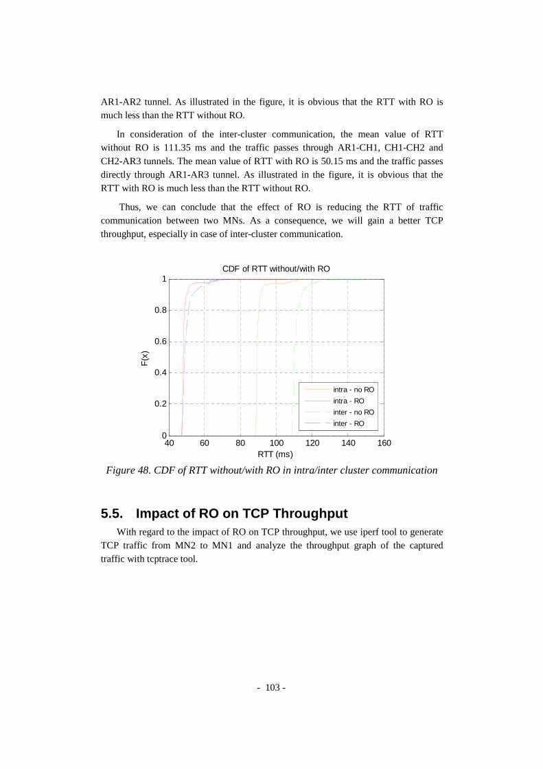
- 103 -
AR1-AR2 tunnel. As illustrated in the figure, it is obvious that the RTT with RO is much less than the RTT without RO.
In consideration of the inter-cluster communication, the mean value of RTT without RO is 111.35 ms and the traffic passes through AR1-CH1, CH1-CH2 and CH2-AR3 tunnels. The mean value of RTT with RO is 50.15 ms and the traffic passes directly through AR1-AR3 tunnel. As illustrated in the figure, it is obvious that the RTT with RO is much less than the RTT without RO.
Thus, we can conclude that the effect of RO is reducing the RTT of traffic communication between two MNs. As a consequence, we will gain a better TCP throughput, especially in case of inter-cluster communication.
Figure 48. CDF of RTT without/with RO in intra/inter cluster communication
5.5. Impact of RO on TCP Throughput With regard to the impact of RO on TCP throughput, we use iperf tool to generate
TCP traffic from MN2 to MN1 and analyze the throughput graph of the captured traffic with tcptrace tool.
40 60 80 100 120 140 1600
0.2
0.4
0.6
0.8
1CDF of RTT without/with RO
RTT (ms)
F(x
)
intra - no RO
intra - RO
inter - no RO
inter - RO

- 104 -
Figure 49. TCP Throughput without/with RO in intra-cluster communication
Figure 49 represents the instantaneous throughput (yellow dots), the moving
average throughput (the peaky red line) calculated as the average of 10 previous yellow dots, and the average throughput of the connection up to that point (the
- 105 -
smooth blue line) in the lifetime of the connection. It is shown that with RO, the TCP throughput increases thanks to smaller RTT between MNs.
6. Conclusion In this chapter, we have proposed a virtualization-based process using User-mode
Linux for developing future mobile Internet protocols. We have implemented the SPMIPv6 framework following practices of this virtualization-based process. Furthermore, the same virtualization technique has been used in combination with VNUML and Ns-2 to form a virtual wireless networking environment for evaluation of the SPMIPv6 framework. Important information as signaling and handover costs, latency, packets loss, RTT delay and TCP throughput has been considered.
We have experimented the SPMIPv6 framework in a virtual IPv6 WMN testbed. We have also provided qualitative and quantitative results to prove the correctness and the advantages of the framework. The SPMIPv6 signaling cost has been evaluated. The cost is expressed in terms of delay caused by the extra signaling in the beginning of the communication. Our results show that the signaling cost is reasonable, especially as it happens only once for each communication.
In consideration of the handover performance, we found that a TCP session is more impacted by mobility than a UDP session due to the congestion control. Besides, as the handover latency depends also on the movement detection time, we believe that in the future link-layer based movement detection will be considered as one approach for reducing the handover latency in SPMIPv6.
In addition, we have implemented the RO extension and evaluated the RO performance in the SPMIPv6 framework with different scenarios of intra-cluster communication and inter-cluster communication. We have analyzed the RO performance results with respect to RTT and TCP throughput. We conclude that PMIPv6 with RO can provide smaller RTT, thus increase the resulting TCP throughput.
The implemented framework combines different hot trends in mobile networking to form a realistic and practical platform for future advanced mobile networking researches. The framework is suitable for different kinds of applications. One of current applications of SPMIPv6 framework with RO support is to deploy rapidly a mobile and wireless communication environment in Integrating Communications for enhanced environmental risk management and citizen’s safety (FP7 CHORIST) which proposes solutions European safety and communications between rescue actors [69]. The signaling mechanism of this framework has been a part of the FP7 CHORIST project where we use Multiprotocol Label Switching (MPLS) for QoS support instead of IP tunnels. MPLS is now become more and more popular, and MPLS support is an important function for edge and core routers. For these reasons, MPLS can be used as a

- 106 -
transition step toward IPv6 in the All-IP architecture and leverages Proxy Mobile IP deployment in the industry. Another application is to spontaneously structure the communication backbone of community based networks (French AIRNET project of the ANR – Agence Nationale pour la Recherche) [70]. The developments are also integrated in the framework of Eurecom’s Open Source Platform “OpenAirInterface” [71].

- 107 -
CHAPTER 6 - MULTI-HOMING FOR WIRELESS BANDWIDTH AGGREGATION AND LOAD-BALANCING IN PMIPV6
This chapter investigates the benefit of multi-homing in PMIPv6. While assuming
that the signaling can maintain simultaneously multiple bindings of a multi-homed MN in PMIPv6, we provide a virtual SCTP tunneling method to overcome the limitation of IP tunneling. The new tunneling method can allow wireless bandwidth aggregation and per-packet load-balancing to multi-interface mobile nodes by distributing packets simultaneously via different active radio interfaces on a per-packet basis. Furthermore, the vSCTP tunneling can reduce the encapsulation overhead over radio links thanks to predictive bundling mechanism, and can reduce tunnel management complexity.
1. Problem Overview While recent researches on vertical handover have taken advantage of multi-
homing by using bi-casting in partially overlapped coverage areas to increase the handover performance [18][19]; we considers PMIPv6 in a multi-homing context comprising of multi-interface mobile nodes and multiple simultaneous access technologies in fully overlapped coverage areas to enable the best use of network resources.
We aim at the Always Best Connected (ABC) vision [72][73][74] which promise wireless bandwidth aggregation and load-balancing features in fully overlapped coverage areas. The ABC concept is considered as the vision beyond vertical handover between heterogeneous radio access technologies. The biggest challenge toward the ABC vision is to enable the simultaneous use of access technologies, which is foreseen as a key feature of 4G. Multi-interface nodes can distribute the traffic simultaneously via different radio access technologies while moving to improve the performance in

- 108 -
terms of throughput, packet loss rate and end-to-end delay. All these issues, related to multi-homing, can be classified into two groups: the interaction between different entities to maintain multiple bindings simultaneously and the method of distributing the traffic simultaneously via multiple active radio interfaces. While the former is protocol-specific, and being discussed within different IEFT working groups, the later is quite open and assumed to be on a per-flow basis.
Driven by the lateral thinking model, this chapter presents an intelligent tunneling framework, referred to as virtual SCTP (vSCTP) tunneling, which outperforms IP tunneling. The vSCTP tunneling framework supports tunnels with multi-homed endpoints and can multiplex packets to multiple radio interfaces on a per-packet basis. As a result, mobile users and operators can benefit from wireless bandwidth aggregation and load-balancing features. Besides, vSCTP tunneling reduces the tunneling overhead over radio interfaces in heavy-load situation thanks to the predictive packet bundling.
2. Multiple Care-of Addresses Registration & Flow Binding The objective of the IETF MONAMI6 working group [75] is to deal with the
simultaneous use of multiple addresses for either Mobile Nodes using Mobile IPv6 (or Mobile Routers for Network Mobility (NEMO) using NEMO Basic Support). The MONAMI6 working group provides a protocol extension that supports the registration of multiple active IPv6 Care-of addresses [76] for a given Home Address to allow the Mobile Node to get Internet access through multiple radio interfaces simultaneously. For doing so, a new identification number, called Binding Unique Identifier (BID), must be carried in each binding for the receiver to distinguish between the bindings corresponding to the same Home Address. The BID is used as a search key for a corresponding entry in the binding cache in addition to the Home Address. When a Home Agent (or a Correspondent Node in case of Route Optimization) checks the binding cache database for the Mobile Node, it searches a corresponding binding entry with the Home Address and BID of the desired binding. If necessary, a Mobile Node can use policy and filter information to look up the best binding per session, per flow, or per packet. As regards NEMO Basic Support, note that a multi-interface Mobile Router can have more than one Home Address. Mobile IPv6 has mechanisms to manage multiple Home Addresses based on Home Agent's managed prefixes such as mobile prefix solicitation and mobile prefix advertisement. However those Home Addresses are seen as separated from each other. The Multiple Care-of Addresses Registration extension recommends assigning only a single Home Address to a Mobile Router with the assumption that applications will not need to be aware of the multiplicity of Home Addresses.

- 109 -
Also in the MONAMI6 working group, the concepts of flow and flow binding are proposed: a flow is defined as one or more connections having the same flow identifier. A single connection is identified by the source and destination IP addresses, transport protocol number and the source and destination port numbers. A flow binding is a mobility binding extended with a flow identifier; it associates a particular flow to a Care-of Address without affecting other flows using the same Home Address.
An extension for flow binding [77] introduces the Flow Identifier Option, which is included in the Binding Update message and used to describe a flow to the recipient of the Binding Update. Using the Flow Identifier Option introduced in this specification a Mobile Node or Mobile Router can bind one or more flows to a Care-of Address while maintaining the reception of other flows on another Care-of Address. If the IP tunneling method and the flow binding are used to distribute flows via multiple active radio interfaces, the decision for flow binding must be done by the Mobile Nodes or Mobile Routers, based on local policies and based on information about network characteristics. Flow Binding extensions are host-based and require host involvement to provide information of host flows which is necessary for flow binding, hence are not always directly applicable.
Using IP tunneling with Flow Binding to distribute packets on a per-flow basis has certain shortcomings. While moving from one wireless link to another, the dynamic nature of the network characteristic can also has negative impact on the flow QoS. As a result, the performance (e.g. throughput, end-to-end delay) for both the overall wireless network and the host is limited. Moreover, in a multi-homing context, IP tunneling supports only one address for each endpoint, the use of IP tunneling for multi-homing implies using a multitude of bi-directional tunnels and results certain complexities for the tunnel management at the Home Agent and Mobile Nodes or Mobile Routers.
In the next section, we present another schema of forwarding traffic simultaneously over multiple interfaces on a per-packet basis.
3. Virtual SCTP Tunneling Framework The virtual SCTP tunneling concept has been first presented in our paper [78], and
is based the Stream Control Transmission Protocol (SCTP) which is designed to supports multi-streaming and multi-homing [33][34]. The virtual term signifies the fact that we apply the concepts of SCTP to tunnels having multi-homed endpoints. As a result, a virtual SCTP tunnel and a SCTP association are isomorphic, i.e. can be mapped onto each other, and we can reuse the design, and implementation of SCTP with minor modifications, principally in the encapsulating packet structure. The virtual SCTP tunneling is considered as a lightweight SCTP in terms of functionalities.

- 110 -
3.1. Conceptual Architecture We consider a tunnel having multi-homed endpoints as a virtual SCTP association
between two virtual SCTP endpoints. For a bi-directional tunnel, a pair of encapsulator and decapsulator must exist at each tunnel endpoint. The encapsulator is considered as the entry point of the tunnel, and the decapsulator is considered as the exit point of the tunnel. In general, the same tunnel can be shared by different connections.
Figure 50. A bi-directional virtual SCTP tunnel
For a normal encapsulation process, whenever an incoming packet is forwarded to the encapsulator, it will be encapsulated in an encapsulating packet which will later be delivered back to the IP routing layer. Instead of having packets distributed rigidly on a per-flow basis, in which each flow is mapped to a predefined radio interface, an intelligent scheduler is introduced inside the encapsulator to allow the cooperation of different active radio interfaces and provides dynamic and flexible per-packet forwarding. A meter estimates the inter-arrival time of the incoming traffic, which is later used by the scheduler for the predictive packet bundling algorithm. On receiving an encapsulating packet, the decapsulator strips off the outer header, restores original encapsulated packets and delivers them back to the routing layer.
3.2. Encapsulating Packet Structure and Packet Bundling
The virtual SCTP tunneling method can bundle multiple small packets in one encapsulating datagram in case that multiple incoming packets are ready for processing in the tunnel’s queue. A similar technique called small packet aggregation has been proposed and analyzed to be beneficial in [79]. This technique allows all encapsulated packets between the two vSCTP endpoints to share the same IP header and therefore reduces significantly the tunneling overhead over the radio interfaces. As there is no need to de-multiplex the traffic to particular applications at tunnel endpoints, the SCTP common header is eliminated to optimize the encapsulating datagram structure.

- 111 -
Figure 51. An encapsulating datagram
In the absence of packet bundling, the encapsulating datagram structure will be the same as in IP tunneling. Only one bit in the IP header is required to mark the presence of packet bundling; this can be the least significant bit (LSB) of the FlowID field in IPv6 or a reserved bit in IPv4. On presence of packet bundling, each incoming packet will be put in an encapsulating data chunk, of which the chunk header is the same as the 4-bytes SCTP common chunk header and has the form of Tag-Length-Value. Let k denote the number of encapsulated packets in one encapsulating packet; a value of k=1 implies the absence of packet bundling, a value of k>1 implies the presence of packet bundling. Figure 51 shows the encapsulating datagram with k encapsulating chunks (k>1); each encapsulating chunk contains an encapsulated packet. Let si be the size of the ith encapsulated packet. Let MTU, and IPheader respectively be the maximum transmission unit, and the IP header size. The value of k must satisfy the following constraint to avoid the segmentation.
IPheaderMTUskk
ii −≤+∑
=1
4
3.3. Predictive Packet Bundling The decision for packet bundling is basically done based on the tunnel’s queue
length and/or in a predictive manner. The meter measures the inter-arrival time of the incoming stream of packets. Let tn denote the elapsed time between the (n-1)th and nth arrivals, this elapsed time is the instantaneous inter-arrival time of the incoming
stream. The smoothed inter-arrival time at the nth arrival, denoted as τn, is computed
using a smoothing factor α (α ≥ 0.5):
( )ααττ −+= − 11 nnn t
The meter then passes its information to the scheduler. When processing a packet, the scheduler attempts to bundle it with other in-queue packets and forwards the encapsulating packet as soon as possible. If the queue is empty, the scheduler predicts a potential packet bundling, in a threshold-based manner, by using meter’s information and wireless path characteristics. Details on how to compute the threshold using wireless path characteristics require further research and are out of scope of this work.
- 112 -
If potential packet bundling is not allowed, the packet is encapsulated and forwarded immediately; otherwise, the scheduler injects some small waiting delay to the packet without increasing its end-to-end delay over a tolerated threshold. Upon next arrival or time out, the incoming packet is encapsulated and forwarded respectively with or without packet bundling.
3.4. Per-packet Dynamic Forwarding In case that no information of flows is available for flow binding, flows can’t be
differentiated, then the traffic is seen as one big flow and should be distributed through different radio interfaces on a per-packet basis to increase the wireless network performance thanks to the wireless bandwidth aggregation. Per-packet forwarding also provides a better flexibility to increase the load-balancing performance in compare to per-flow forwarding.
3.5. Simplification of Tunnel Management Unlike IP tunneling, virtual SCTP tunneling supports multiple addresses for each
endpoint; therefore it reduces the tunnel management complexity and the system resource usage. Let m denote the number of source endpoint addresses and n denote the number of destination endpoint addresses; it is essential to have only one tunnel device for the communication between the two multi-homed endpoints with virtual SCTP tunneling but mn tunnel devices with IP tunneling. At the two vSCTP endpoints, the destination address list of the virtual SCTP association is synchronized with the Care-of Address list by using predefined SCTP primitives such as Add IP Address and Delete IP Address.
4. Evaluation
4.1. Encapsulation Overhead Consideration While the encapsulation helps to hide away the real topology between the two
endpoints, it requires extra header which causes encapsulation overhead. The optimization of the data plane aims at increasing the effective bandwidth usage (the
utilization) of the network resources. Let s be the average incoming packet size, and k
is the number of encapsulated packet or the number of encapsulating data chunk, whereas
maxkk ≤ ,
+−=
s
IPheaderMTUk
4max
We can evaluate the lower bound of encapsulation overhead of each tunneling mechanism. We define the bandwidth utilization and the header overhead by the following formulas:

- 113 -
ingencapsulat
edencapsulatingencapsulat
B
BBOverhead
−=
OverheadB
BnUtilizatio
ingencapsulat
edencapsulat −== 1
Figure 52. The encapsulation overhead comparison (in percent of total
bandwidth)
Figure 52 shows the header overhead comparison between vSCTP tunneling and IP tunneling over both IPv4 and IPv6 with MTU of 1500 bytes. The overhead of vSCTP tunneling is smaller; therefore better, for packet size smaller than 720 bytes thanks to the bundling ability. While the packet size increases, the number of encapsulating data chunk decreases because the packet size is limited by the frame size, e.g. for Ethernet, the frame size is 1500. There will be a peak whenever the number of encapsulating data chunk decreases and cause the overhead increases in a step function. Step by step, the encapsulation overhead of vSCTP tunneling converges to the overhead value of IP tunneling.
4.2. Delay Consideration Of course, there exists a trade-off between the bandwidth utilization and the
tunneling delay. The delay of vSCTP tunneling is probably bigger than the one of IP tunneling delay because it is potentially influenced by 2 factors: the encapsulating packet transmission delay and the buffering delay (the waiting time for many incoming
0 100 200 300 400 500 600 700 800 900 1000 11000
5
10
15
20
25
30
Average Packet Size (bytes)
Enc
apsu
latio
n O
verh
ead
(%)
Encapsulation Overhead Comparison
IPv6 tunneling
vSCTP over IPv6IPv4 tunneling
vSCTP over IPv4

- 114 -
packets).
The first factor (transmission delay) is reverse proportional to the number of encapsulated IP packets in an encapsulating packet. When the number of encapsulated packet decreases, this factor approaches the IP tunneling delay. Because the transmission delay for vSCTP encapsulation is around the value of
cD
ksIPheader +++ )4( and the transmission delay for IP tunneling is around
cD
sIPheader ++ where s is the average incoming packet size, D is the link speed,
c is the propagation delay, and k is the number of encapsulated packet or the number
of encapsulating data chunk.
The second factor (buffering delay) depends on the traffic pattern. When the number of flows increases, the arrival rate increases, the buffering delay caused by this factor converges to 0. Therefore, to eliminate this factor, we have proposed the predictive packet bundling where the bundling process is predicted by observing the history of the traffic.
4.3. Evaluation of vSCTP tunneling in PMIPv6 The objective of this section is to support the ABC vision in PMIPv6. We consider
PMIPv6 domain as an autonomous system under the control of an operator. The PMIPv6 domain is composed of different ARs controlling heterogeneous radio access technologies. From this point of view, PMIPv6 can be used for inter access system handover within an operator. A MN can have multiple interfaces of different radio access technologies; each interface has its own IP address within the PMIPv6 domain. Without loss of generality, we consider here only 3GPP and WLAN access networks for the simplicity.
Figure 53: Virtual SCTP endpoint and virtual SCTP association concepts

- 115 -
We consider the vSCTP tunnel between two virtual SCTP endpoints as shown in the Figure 53. One virtual SCTP endpoint is the LMA, and the other virtual SCTP endpoint, comprising multiple virtual interfaces, is a set of ARs. Each AR is considered as a virtual interface. The tunnel is fixed between the LMA and a set of ARs, allows the collaboration between ARs, and is shared by different MNs.
Figure 54: Mappings between different spaces
Figure 54 shows the mapping between different spaces: MN's edge IP addresses space, tunnels space, and ARs space. Assume that tun{i, j} denotes the tunnel between the LMA and the set of {ARi, ARj}. Packets addressed to MN having access to ARi and ARj will go through the tun{i, j} . Given that the MN has 2 interfaces with @1 and @2
respectively to be the edge IP addresses of the first interface and the second interface in the PMIPv6 domain. At one given moment, the first interface has access to ARi, and the second interface has access to ARj. Routing entries for @1 and @2 point at the same tunnel tun{i, j} . Now this MN moves from ARj to ARk. On receiving the PBU, the LMA updates its routing table to redirect MN’s packet to the tun{i, k}. The tunnel is responsible for dynamically distributing MN’s flows or packets to the most suitable AR. Those tunnels can be manually created by administrators, or incrementally created by observing the Location Registration process and the forwarding state in the LMA and ARs.
We carried out an observation of this schema under Ns-2 version 2.29. We constructed a PMIPv6 domain using IPv6 with only one LMA and two ARs. For the first step, the interaction between ARs and the LMA follows the standard. The capacity and the propagation delay of the AR-LMA links are respectively 10 Mbps and 10 ms. We measure the tunneling goodput and the average tunneling delay while varying parameters such as the number of flows, the incoming IP packet size and the number of encapsulating data chunks k.

- 116 -
Figure 55. Normalized tunneling goodput vs. number of flows
Figure 56. Tunneling delay vs. number of flows
Figure 55 shows tunneling goodput normalized by the throughput of encapsulating packets versus the number of flows when the inter-arrival time of each flow is 20 ms and the incoming packet size is 300 bytes, that is enough for VoIP packets (e.g., if G.711 is used, the VoIP packet size is only 220 bytes). It shows that larger k provides better efficiency than smaller k. Figure 56 points out that, in normal condition, larger k
0 10 20 30 40 50 60 70 80 90 1000.8
0.82
0.84
0.86
0.88
0.9
0.92
Number of data flows
Nor
mal
ized
tun
nelin
g go
odpu
t
k=1
k=2
k=3
k=4
0 10 20 30 40 50 60 70 80 90
20
30
40
50
60
70
80
90
100
110
Number of data flows
Tun
nelin
g de
lay
(ms)
Normal condition
Overloadedcondition
Saturatedpoint
k=1
k=2
k=3
k=4

- 117 -
slightly increases the average tunneling delay. In conclusion, the number of encapsulating chunks k may be set to one to have the smallest tunneling delay but can be maximized for applications that tolerate to the delay and jitter to have better efficiency. The choice for this value k is an open QoS problem.
From the point of view of MNs, the use of such virtual SCTP tunneling in PMIPv6 provides a larger wireless bandwidth, of which the capacity in terms of bandwidth is the total capacity of the two wireless links. Assume that a MN has two flows: one for the file transfer and the other for the audio/video stream. The virtual SCTP tunneling allows the LMA to use the WLAN AR for the file data flow and the 3GPP AR for the audio/video flow. This scenario can even be extended to per-packet basis, on which, different packets of the same flow are distributed through different interfaces. Figure 57 illustrates the aggregated wireless bandwidth feature with the use of virtual SCTP
tunneling. Consider the following simulation. The 3GPP link capacity is 2 Mbps and the WLAN link capacity is 5 Mbps. The virtual SCTP tunneling is scheduled so that the traffic is distributed to different links on a per-packet basis, and in a simple manner with the Round-robin algorithm. We define the offered load as the total traffic volume sent to the MN and measure the MN goodput that is the total traffic volume received by the MN. From the result, the aggregated bandwidth is not completely the total of the two link bandwidth as expected. This is due to the fact that the two links have different capacity meanwhile we use the Round-robin algorithm which distribute packets equally to the two links. A weighted Round-robin algorithm will optimize the vSCTP tunneling (the dashed black line).
Figure 57. Aggregated bandwidth with virtual SCTP tunneling
Continuing with the above scenario of aggregated wireless bandwidth: Provided
0 1 2 3 4 5 6 7 8 9 100
1
2
3
4
5
6
7
8
9
10
Offered load (Mbps)
Goo
dput
(M
bps)
Theoretical capacity limit
Optimised vSCTP tunneling
IP tunneling on WLAN link
IP tunneling on 3GPP linkvSCTP tunneling

- 118 -
that at one moment, the number of served MNs in the 3GPP coverage increases so that the load on the 3GPP link is going to be saturated, the tunnel can switch the traffic of certain MNs from the 3GPP link to the WLAN link to improve the global performance in terms of number of "satisfied" MNs (with regard to the MN profile and the QoS). From the point of view of operators, the use of virtual SCTP tunneling provides load-balancing mechanism that allows the network operators to manage the load in their network. Our research results have also been cited in [80] to motivate the need of multi-homing support in PMIPv6.
4.4. Evaluation of vSCTP tunneling in NEMO NEMO Support [81] provides seamless mobility to Mobile Networks, which are
defined as network segments or subnets that can move and attach to any points in the Internet topology. A Mobile Network includes one or more Mobile Routers (MRs) which connect it to the global Internet. Nodes behind the Mobile Router, called Mobile Network Nodes (MNNs), are Local Fixed Nodes (LFNs), Local Mobile Nodes (LMNs) and Visiting Mobile Nodes (VMNs). For the related terminology, see [82]. NEMO Basic Support [83] describes protocol extensions to Mobile IPv6 to enable support for network mobility. One advantage of NEMO Basic Support is that the Mobile Network Nodes need not be aware of the actual location and mobility of the mobile network. With some approaches for Route Optimization [84], it might be necessary to reveal the point of attachment of the Mobile Router to the Mobile Network Nodes. This may mean a tradeoff between mobility transparency and Route Optimization.
NEMO Basic Support describes protocol extensions to Mobile IPv6 to enable support for network mobility. A Mobile Network is a network segment or subnet that can move and attach to any point in the Internet. A Mobile Network can only be accessed via Mobile Routers that manage its movement. Mobile Networks have at least one Mobile Router serving them. A Mobile Router maintains a bi-directional tunnel to a Home Agent (HA) that advertises an aggregation of Mobile Networks to the infrastructure. A Mobile Router has a unique Home Address through which it is reachable when it is registered with its Home Agent. The Home Address is configured from a prefix aggregated and advertised by its Home Agent. The prefix could be either the prefix advertised on the home link or the prefix delegated to the Mobile Router. When the Mobile Router has multiple interfaces or when there are multiple prefixes in the home link, the Mobile Router can have more than one Home Address.
When the Mobile Router moves away from the home link and attaches to a new access router, it acquires a Care-of Address from the visited link. As soon as the Mobile Router acquires a Care-of Address, it immediately sends a Binding Update to its Home Agent as described in [22]. When the Home Agent receives this Binding Update, it creates a cache entry that binds the Mobile Router's Home Address to its Care-of Address at the current point of attachment. The Mobile Router sets a flag (R) in the Binding Update to indicate to the Home Agent that it acts as a Mobile Router

- 119 -
and provides connectivity to nodes in the Mobile Network.
The extension defines a new Mobility Header Option for carrying prefix information. If the Mobile Network has more than one IPv6 prefix, it can include multiple prefix information options in a single Binding Update. The Home Agent sets up forwarding for each of these prefixes to the Mobile Router's Care-of Address and acknowledges the Binding Update by sending a Binding Acknowledgement to the Mobile Router. Once the binding process finishes, a bi-directional tunnel is established between the Home Agent and the Mobile Router. The tunnel end points are the Mobile Router's Care-of Address and the Home Agent's address. All traffic between the Local Fixed Nodes and Correspondent Nodes passes through the Home Agent and the tunnel. The Route Optimization is out of scope of NEMO Basic Support.
Even though NEMO Basic Support does not discuss multi-homing, [85] provides a full analysis on multi-homing in NEMO with different cases of multi-homing and related issues. In [18], an IPv6 soft handover extension for NEMO Basic Support (NEMO-SHO) with multi-interface Mobile Routers, using packet bicasting and combining, has been proposed and experimented.
When applying vSCTP tunneling to NEMO, one virtual SCTP endpoint is the Home Agent, and the other is the multi-homed Mobile Router. Traffic from Correspondent Nodes to Local Fixed Node is tunneled between the Home Agent and the Mobile Router through the virtual SCTP tunnel (see Figure 58).
Encapsulator
(meter + scheduler)
Decapsulator
Wireless PathsVitual SCTP Endpoint
(Home Agent)
Virtual SCTP Endpoint
(Mobile Router)
@HA
@CoA1
@CoA2
@CoAn Encapsulator
(meter + scheduler)
Decapsulator
Figure 58. A bi-directional virtual SCTP tunnel in NEMO
We carry out the simulation under Ns-2 (version 2.29) with NO Ad-Hoc (NOAH) routing extension and with our extensions for multi-interface Mobile Routers, virtual
SCTP tunneling and manual routing in the hierarchical addressing mode. The scheduler inside the tunnel’s encapsulator distributes the traffic to different Care-of Addresses, i.e. to different radio interfaces, on a per-packet basis, and in a simple manner using the
Round-robin algorithm. The meter uses a smoothing factor α of 0.6 for computing the
smoothed inter-arrival time.

- 120 -
Figure 59. Simulation topology
The IPv6 simulation topology (see Figure 59) includes one Home Agent and two Access Routers (ARs). Both Access Routers have the capacity of 5.5 Mb/s. Different values of delay are used for different Home Agent-Access Router links as the first step to simulate the difference in wireless path characteristics. Different error transmission characteristics will be considered in our future work. It is assumed that each Mobile Network has only one Mobile Router which has two egress interfaces; each interface associates to one Access Router via the wireless link. The scenarios in which each Mobile Network has multiple MRs [86] are not considered in our work.
All Mobile Routers are in the coverage of both Access Routers and uniformly positioned in this region. This simulates a fully overlapped coverage area of different radio access technologies and allows Mobile Routers to have simultaneous access to the routing infrastructure, i.e. to the Internet. We consider 5 different Mobile Networks; the number of Local Fixed Nodes inside each Mobile Network is 15, 10, 10, 5, and 5 respectively.
We use two traffic classes to survey service differentiation: the first traffic class, using G.728 as Pulse Code Modulation codec, consists of 20 VoIP flows, each flow creates VoIP packets of 100 bytes (52-bytes UDP payload) at a 20-ms sample interval; the second traffic class consists of 25 video or data flows, each flow creates packets of 1024 bytes at a 20-ms interval. A random bijection between the set of Correspondent Nodes and the set of Local Fixed Nodes is initialized. A flow is initialized for each pair CN-LFN and is randomly bound to a radio interfaces as follows: for each run, generate a random number r in the range of 0.2 and 0.8 uniformly; for each flow, generate a random number x in the rage of 0 and 1; if x < r, bind the flow to the first interface, otherwise, bind the flow to the second interface.

- 121 -
Figure 60. Simulation results for the second traffic class
0 1 2 3 4 5 6 7 8 9 10 110
0.2
0.4
0.6
0.8
1
Offered load (Mb/s)
Thr
ough
put
(Mb/
s)a. Througput (class 1)
IPv6
vSCTP k=1
vSCTP k>1
Heavy-load Overload
0 5 10 15 20 25 30 35 40 450
5
10
15
20
25
30
Number of active LFNs
Rat
e (%
)
b. Packet loss rate (class 1)
IPv6
vSCTP k=1
vSCTP k>1
0 5 10 15 20 25 30 35 40 4520
40
60
80
100
120
140
160
Number of active LFNs
Del
ay (
ms)
c. Average end-to-end delay (class 1)
IPv6
vSCTP k=1
vSCTP k>1
Heavy-load Overload
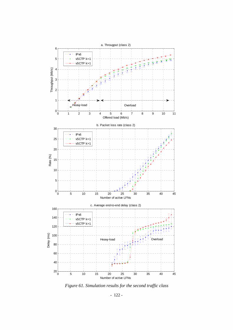
- 122 -
Figure 61. Simulation results for the second traffic class
0 1 2 3 4 5 6 7 8 9 10 110
1
2
3
4
5
6
Offered load (Mb/s)
Thr
ough
put
(Mb/
s)
a. Througput (class 2)
IPv6
vSCTP k=1
vSCTP k>1
Heavy-load Overload
0 5 10 15 20 25 30 35 40 450
5
10
15
20
25
30
Number of active LFNs
Rat
e (%
)
b. Packet loss rate (class 2)
IPv6
vSCTP k=1
vSCTP k>1
0 5 10 15 20 25 30 35 40 4520
40
60
80
100
120
140
160
Number of active LFNs
Del
ay (
ms)
c. Average end-to-end delay (class 2)
IPv6
vSCTP k=1
vSCTP k>1
Heavy-load Overload
- 123 -
20 flows of the first traffic class are gradually initialized at random starting time. Later, 25 remaining flows of the second traffic class are initialized in the same manner. The observation is carried out, with 20 simulation runs, on the following metrics: system offered load, traffic class throughput and average end-to-end delay. For each metric, we also estimate and plot the 95% confidence interval of sample means.
Figure 60 shows results for the first traffic class, and Figure 61 shows results for the second traffic class. Figure 60a and 61a represent the impact of system offered load on each traffic class throughput while Figure 60b, 60c, 61b and 61c represent the impact of number of active Local Fixed Nodes on the packet loss rate and the average end-to-end delay for each traffic class. In all cases, the virtual SCTP tunneling with predictive packets bundling feature (i.e. the number of encapsulating chunk k is greater than one) provides the highest throughput and the lowest packet loss rate. For example, see Fig. 55b, if the maximum tolerated packet loss rate for a VoIP connection is 5%, the maximum number of supported active Local Fixed Nodes when using IPv6 tunneling, virtual SCTP tunneling without and with bundling is respectively 24 (the worst), 28 (better) and 29 (the best). In heavy-load condition, the virtual SCTP
tunneling provides smaller average end-to-end delay and better throughput for both traffic classes thanks to the load-balancing feature. In overload condition, it provides higher throughput and smaller packet loss rate with larger delay as a trade-off. However this trade-off is worth for applications, e.g. data transfer or video streaming, where lost packets cause negative impact on the QoS. Besides, our observation also shows that service differentiation in NEMO is still an open challenge that requires more research efforts.
5. Conclusion In this chapter, we have proposed a novel intelligent tunneling framework, referred
to as virtual SCTP tunneling that enables the Always Best Connected vision for PMIPv6 and NEMO. The new tunneling method can allow wireless bandwidth aggregation and per-packet load-balancing to multi-interface Mobile Nodes or Mobile Routers by distributing packets simultaneously via different active radio interfaces on a per-packet basis. Moreover, thanks to bundling mechanism, the vSCTP tunneling can reduce the encapsulation overhead over radio links by allowing many small packets to share the same IP header. The virtual SCTP tunneling is optimized to achieve better bandwidth utilization without compromise the tunneling delay thanks to the predictive packet bundling process. Besides, we can dynamically control the trade-off between the delay and the header overhead to have best performance in different situations.
We considered PMIPv6 in a context of Always Best Connected where the simultaneous use of interfaces and the dynamic change of IP addresses are inseparable. Applying the vSCTP tunneling to PMIPv6, traffic to a multi-homed MN could be forwarded simultaneously via different interfaces. We implemented the first proof-of-
- 124 -
concept for validating the simultaneous access scenario under Ns-2. The simulation results show that the new tunneling method is beneficial for both users and operators. From the user perspective, the bandwidth is improved with wireless bandwidth aggregation. From the operator perspective, the system utility can be improved by switching flows/packets to the right radio interface. As regards NEMO, applying the vSCTP tunneling framework to NEMO is advantageous over the existing per-flow solution using IP tunneling in terms of throughput, packet loss rate, as well as end-to-end delay.
Further research on the vSCTP framework could be defining and modeling an intelligent interface selection algorithm that should satisfy both network operators and mobile users while considering the impact of different factors such as mobility, network traffic characteristics, limited coverage area, etc. A deeper direction could be optimizing the scheduling algorithm in consideration of mobility, service differentiation and feedback information about the wireless link characteristics and wireless link capacity.

- 125 -
CHAPTER 7 - CONCLUSIONS AND OUTLOOK
1. Conclusion
Providing mobility support in the Internet has been a long-standing challenge, and a variety of host-based mobility management solutions, such as MIPv4, MIPv6, mSCTP, and HIP have been designed. These host-based mobility management solutions require host stack changes, not only from the side of the mobile devices themselves but also from the infrastructure as well as their correspondent nodes in the world wide Internet. It is the tremendous diversity in mobile devices and increasing Internet applications which have created difficulties for the adoption of host-based mobility management, and as a consequence, motivates the need for a new network-based mobility management paradigm.
Proxy Mobile IPv6 (PMIPv6) protocol, a network-based mobility management solution, is being seen as the protocol for achieving a common mobile core network, accommodating different access technologies such as WiMAX, 3GPP and 3GPP2 radio networks. It will be key protocol for achieving inter-working between various access technologies. In this dissertation, we focus on challenges to support Proxy Mobile IPv6 in heterogeneous wireless networks of which the network topology can be statically well defined but more likely to be arbitrary and organized in a spontaneous wireless mesh manner.
Scalability extension for PMIPv6 (SPMIPv6). The first challenge concerns the scalability of PMIPv6 in large heterogeneous wireless networks. Scalability is a key success factor for business applications in a dynamic environment and can be defined as the ability of a network to adjust or maintain its performance as the size of the network increases. Constructing a scalable architecture which provides mobility service using PMIPv6 is not an easy task, especially in the context of spontaneous networks where the topology is arbitrary and can be dynamically created and changed. We have extended PMIPv6 to provide scalability in large heterogeneous wireless network in a cluster-based manner. The framework is called Scalable Proxy Mobile IPv6 (SPMIPv6). We have evaluated the scalability of our SPMIPv6 framework in a

- 126 -
wireless mesh network context. A mathematical model has been used to investigate the scalability of the framework with consideration of the wireless mesh network size, mobile node density, and average mobile speed. The metrics, used to reflect the scalability, are the probability of successful per-cell handover and the successful per-cell handover rate. Numerical results show that SPMIPv6 provides a mechanism for inter LMAs interactions which can horizontally and gradually scale the WMN. This approach is less expensive than replacing the centralized LMA and avoids the single point of failure problem in PMIPv6.
Route Optimization (RO) for SPMIPv6. Another interesting topic is the Route Optimization which resolves the suboptimal triangle route in PMIPv6. Supporting Route Optimization becomes more complicated when mobility and scalability is taken into consideration in spontaneous networks. We have considered route optimization support for PMIPv6 in general, and in particular applied in SPMIPv6 with respect to different possible RO cases. Our design provides, at the same time, RO and scalability and inherits all features from PMIPv6.
Network-based Movement Detection in Heterogeneous Environments. An important aspect of any mobility protocol is the movement detection. However, detecting the attachment in network-based mobility management is not trivial, especially in a heterogeneous environment, and requires different efforts for each wireless access technologies. The first key idea is based on the converged IPv6 layer, which is the waist of the protocol stack and the common core for All-IP based next generation networks, to cover the heterogeneity of mobile devices, applications and radio access technologies. From our point of view the network must be responsible for the movement detection in PMIPv6. The hints for movement detection can be the Link-Layer Events, Traffic Monitoring Events or DNAv6. We have introduced an enhanced IP-Layer network-based movement detection mechanism. The advantage of our proposal is that it doesn’t require any special software on the mobile devices and is independent from the access technologies. This will help to promote PMIPv6 in practice gradually and later to optimize PMIPv6 with link-layer specific movement detection mechanism in long terms. The proposed mechanism is independent from the link-layer and accepts all existing link-layer device drivers. All the intelligence is immigrated to the mobile access gateway to support a widest range of mobile devices.
Implementation of SPMIPv6 with RO support in a Virtualization-Based Process. We have proposed a virtualization-based process using User-mode Linux for implementing the SPMIPv6 framework with RO support under Linux operating system. Furthermore, the same virtualization technique has been used in combination with VNUML and Ns-2 to form a virtual wireless networking environment for evaluation of the SPMIPv6 framework. We setup virtual wireless mesh testbeds with the scope of being as close as possible to real experimentation results, which later allowed us to migrate to the real testbed in the scope of the FP7 CHORIST project with almost no efforts. Different scenarios were defined and experimented in both virtual

- 127 -
and real testbed. Important information, as signaling and handover costs, latency, packets loss, RTT delay and TCP throughput, has been considered.
Evaluation of PMIPv6 with Scalability and RO support. The SPMIPv6 signaling cost is expressed in terms of delay caused by the extra signaling in the beginning of the communication. Our results show that the signaling cost is reasonable, especially as it happens only once for each communication. In consideration of the handover performance, we found that a TCP session is more impacted by mobility than a UDP session due to the congestion control. Besides, as the handover latency depends also on the movement detection time, we believe that in the future, a link-layer based movement detection will be considered as one approach for reducing the handover latency in SPMIPv6. The RO has been evaluated in the SPMIPv6 framework with both scenarios of intra-cluster communication and inter-cluster communication. We have analyzed the RO performance results with respect to RTT and TCP throughput. We conclude that PMIPv6 with RO can provide smaller RTT, thus increase the resulting TCP throughput.
Applications of the SPMIPv6 Framework. The implemented framework combines different hot trends in mobile networking to form a realistic and practical platform for future advanced mobile networking researches. The framework is suitable for different kinds of applications. One of current applications is to deploy rapidly a mobile and wireless communication environment in Integrating Communications for enhanced environmental risk management and citizen’s safety (FP7 CHORIST) which proposes solutions for European safety and communications between rescue actors. In the scope of this project, we have foreseen the use of Multiprotocol Label Switching (MPLS) for QoS support instead of IP tunnels. MPLS is now becoming more and more popular, and MPLS support is an important function for edge and core routers. For these reasons, MPLS can be used as a transition step toward IPv6 in the All-IP architecture and leverages Proxy Mobile IP deployment in the industry. Another application is to spontaneously structure the communication backbone of community based networks (French AIRNET project of the ANR – Agence Nationale pour la Recherche). The developments have also been integrated in the framework of Eurecom’s Open Source Platform “OpenAirInterface”.
VSCTP Tunneling for Multi-homing Support in PMIPv6. In next generation networks, mobile users can access services anywhere and anytime thanks to the availability of mobile devices are equipped with multiple network interfaces of different radio access technologies in parallel. We have studied PMIPv6 in a context of Always Best Connected which considers multi-interface mobile nodes and multiple simultaneous access technologies in fully overlapped coverage areas to enable the best use of network resources. We provided a virtual SCTP tunneling method to overcome the limitation of IP tunneling. The new tunneling method can permit wireless bandwidth aggregation and per-packet load-balancing to multi-interface mobile nodes by distributing packets simultaneously via different active radio interfaces on a per-

- 128 -
packet basis. Moreover, the vSCTP tunneling can reduce the encapsulation overhead over radio links thanks to predictive bundling mechanism, and reduce tunnel management complexity.
We implemented the first proof-of-concept for validating the simultaneous access scenario under Ns-2. The simulation results show that the new tunneling method is beneficial for both users and operators. From the user perspective, the bandwidth is improved with wireless bandwidth aggregation. From the operator perspective, the system utility can be improved by switching flows/packets to the right radio interface. We also applied the vSCTP tunneling framework to NEMO, which is a solution for network mobility without modifications to local fixed nodes, and showed that it is advantageous over the existing per-flow solution in terms of throughput, packet loss rate, as well as end-to-end delay.
2. Limitation of the work PMIPv6 Addressing Model. This is the first limitation of this work as our results
rely only on the shared prefix assumption due to requirements from different projects. The results should be experimented and validated as well in case of Per-MN prefix. In this case, we will need to define and implement a mechanism to statically or dynamically allocate prefix to MNs.
Granularity of Communication Detection. The second limitation in the current implementation of SPMIPv6 is that the network can only differentiate communications identified by a couple of source and destination addresses. A smaller granularity such as per-flow differentiation will allow more multi-homing scenarios.
Impact of Movement Detection on the Handover Latency. We also experienced an impact of movement detection delay on the handover latency. The results would have been better and more reliable with real layer-2 movement detection.
Impact of mobility on RO. The impact of mobility on RO has not been investigated throughout and is assigned with a low-priority within the projects we have been involved.
3. Perspectives QoS with Path Diversity. The PMIPv6 protocol together with scalability, multi-
homing and the RO extensions create path diversity, and hence, traffic can be forwarded simultaneously through multiple paths. The communication between mobile nodes can be delegated to the communication between their MAGs, either in a direct manner or indirect manner via their LMAs. Each path has its own characteristics including loss rate, delay and bandwidth. With such vision, Service Differenciation

- 129 -
QoS in PMIPv6 is an interesting challenge. Providing QoS service to a flow can be mapped to the problem of mapping a flow to given paths while considering the QoS demand, path characteristics, current network situation, and mobility pattern. We can also choose symmetric communication which uses the same path for both directions, or chose asymmetric communication which uses different paths for different directions.
Optimized Scheduler for vSCTP. Further research on the vSCTP framework could be defining and modeling an intelligent interface selection algorithm that should satisfy both network operators and mobile users while considering the impact of different factors such as mobility, network traffic characteristics, limited coverage area, etc. A deeper direction could be optimizing the scheduling algorithm in consideration of mobility, service differentiation and feedback information about the wireless link characteristics and wireless link capacity.
Combination of NEMO and PMIPv6. Besides PMIPv6, NEMO also follows the network-based philosophy which requires no modification to network local fixed nodes. Combining SPMIPv6 and NEMO within the cluster-based architecture can support the mobility of CHs and ARs. Thus, it provides an added-on mechanism to handle the topology changes in the wireless mesh backbone while ensuring the mobility service to MNs. Furthermore, a combination of PMIPv6 and NEMO will support not only Local Fixed Nodes but also Local Mobile Nodes and Visited Mobile Nodes without any modification to NEMO Basic Support. This combination can also be another solution for nested NEMO [87][88] when the MN itself becomes the gateway of a Personal Area Network and plays the role of a Mobile Router.
.

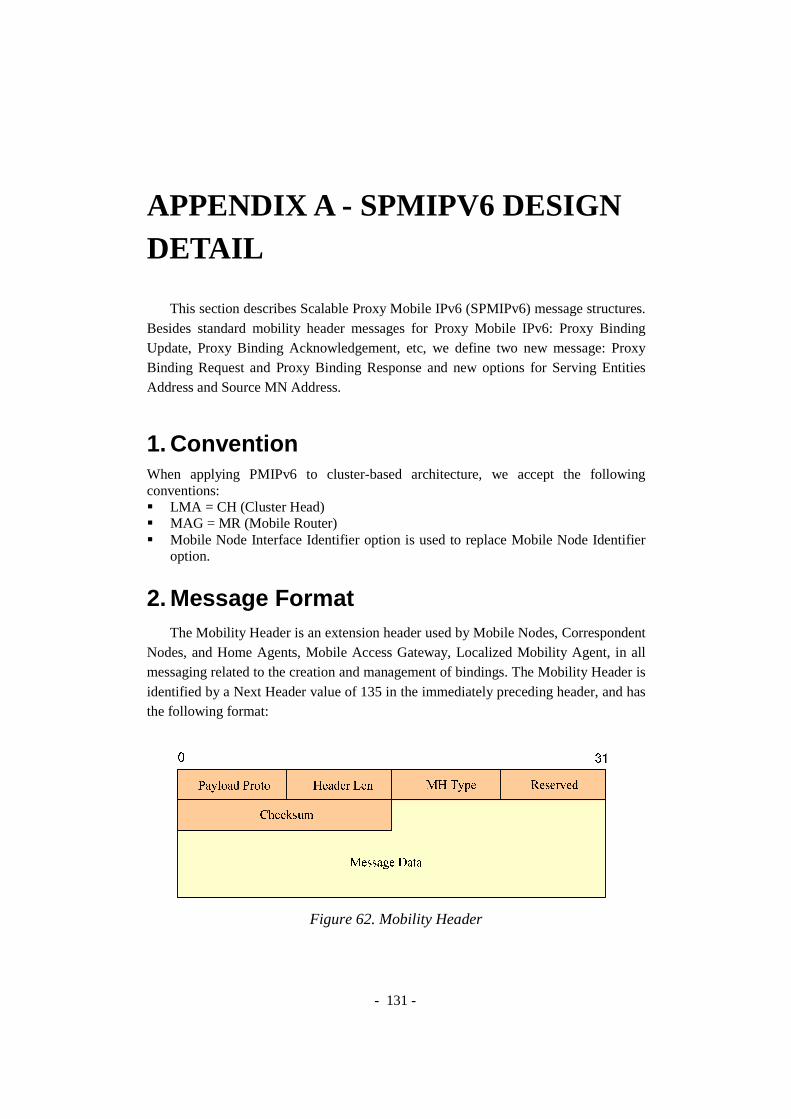
- 131 -
APPENDIX A - SPMIPV6 DESIGN DETAIL
This section describes Scalable Proxy Mobile IPv6 (SPMIPv6) message structures. Besides standard mobility header messages for Proxy Mobile IPv6: Proxy Binding Update, Proxy Binding Acknowledgement, etc, we define two new message: Proxy Binding Request and Proxy Binding Response and new options for Serving Entities Address and Source MN Address.
1. Convention When applying PMIPv6 to cluster-based architecture, we accept the following conventions: � LMA = CH (Cluster Head) � MAG = MR (Mobile Router) � Mobile Node Interface Identifier option is used to replace Mobile Node Identifier
option.
2. Message Format The Mobility Header is an extension header used by Mobile Nodes, Correspondent
Nodes, and Home Agents, Mobile Access Gateway, Localized Mobility Agent, in all messaging related to the creation and management of bindings. The Mobility Header is identified by a Next Header value of 135 in the immediately preceding header, and has the following format:
Figure 62. Mobility Header

- 132 -
� Payload Proto 8-bit selector. Identifies the type of header immediately following the Mobility Header. Uses the same values as the IPv6 Next Header field. Implementations conforming to this specification SHOULD set the payload protocol type to IPPROTO_NONE (59 decimal).
� Header Len
8-bit unsigned integer, representing the length of the Mobility Header in units of 8 octets, excluding the first 8 octets. The length of the Mobility Header MUST be a multiple of 8 octets.
� MH Type 8-bit selector. Identifies the particular mobility message in question. An unrecognized MH Type field causes an error indication to be sent.
� Reserved 8-bit field reserved for future use. The value MUST be initialized to zero by the sender, and MUST be ignored by the receiver.
� Checksum 16-bit unsigned integer. This field contains the checksum of the Mobility Header. The checksum is calculated from the octet string consisting of a "pseudo-header" followed by the entire Mobility Header starting with the Payload Proto field. The checksum is the 16-bit one's complement of the one's complement sum of this string.
� Message Data A variable length field containing the data specific to the indicated Mobility Header type. Any options MUST appear after the fixed portion of the message data specified in this document. The presence of such options will be indicated by the Header Len field within the message. When the Header Len value is greater than the length required for the message specified here, the remaining octets are interpreted as mobility options. These options include padding options that can be used to ensure that other options are aligned properly, and that the total length of the message is divisible by 8. Alignment requirements for the Mobility Header are the same as for any IPv6 protocol Header. That is, they MUST be aligned on an 8-octet boundary.
2.1. Proxy Binding Update Message
A Binding Update message that is sent by a mobile access gateway to a local mobility anchor is referred to as the "Proxy Binding Update" message. A new flag (P) is included in the Binding Update message. The rest of the Binding Update message format remains the same as defined in the RFC 3775 and with the additional (R) and (M) flags as specified in the RFC 3963 and the RFC 4140 respectively.
IPv6 header (src= MAG@, dst= LMA@) Mobility header:

- 133 -
Figure 63. Proxy Binding Update Message
� Sequence #
A 16-bit unsigned integer used by the receiving node to sequence Binding Updates and by the sending node to match a returned Binding Acknowledgement with this Binding Update.
� Acknowledge (A) The Acknowledge (A) bit is set by the sending mobile node to request a Binding Acknowledgement be returned upon receipt of the Binding Update.
� Home Registration (H) The Home Registration (H) bit is set by the sending mobile node to request that the receiving node should act as this node's home agent.
� Link-Local Address Compatibility (L) The Link-Local Address Compatibility (L) bit is set when the homeaddress reported by the mobile node has the same interface identifier as the mobile node's link-local address.
� Key Management Mobility Capability (K)
If this bit is cleared, the protocol used for establishing the IPsec security associations between the mobile node and the home agent does not survive movements. It may then have to be rerun.
� Proxy Registration Flag (P)
A new flag (P) is included in the Binding Update message to ndicate to the local mobility anchor that the Binding Update essage is a proxy registration. The flag MUST be set to the alue of 1 for proxy registrations and MUST be set to 0 for direct registrations sent by a mobile node.
� Lifetime
16-bit unsigned integer. The number of time units remaining before the binding MUST be considered expired. A value of zero indicates that the Binding Cache entry for the mobile node MUST be deleted. (In this case the specified care-of address MUST also be set equal to the home address.) One time unit is 4 seconds.
� Mobility Options

- 134 -
As per this specification, the following mobility options are valid in a Proxy Binding Update message (the grey options are not currently implemented): � Mobile Node Identifier option (mandatory) � Home Network Prefix option (mandatory) � Handoff Indicator option (mandatory) � Access Technology Type option (mandatory) � Timestamp option (optional) � Mobile Node Interface Identifier option (optional � mandatory) � Link-local Address option (optional)
2.2. Proxy Binding Acknowledgement Message
A Binding Acknowledgement message that is sent by a local mobility anchor to a mobile access gateway is referred to as the "Proxy Binding Acknowledgement" message. A new flag (P) is included in the Binding Acknowledgement message. The rest of the Binding Acknowledgement message format remains the same as defined in RFC 3775 [22] and with the additional (R) and (M) flags as specified in RFC 3963 [83] and RFC 4140 [27] respectively.
IPv6 header (src=LMA@, dst=MAG@) Mobility header:
Figure 64. Proxy Binding Acknowledgement Message
� Proxy Registration Flag (P)
A new flag (P) is included in the Binding Acknowledgement message to indicate that the local mobility anchor that processed the corresponding Proxy Binding Update message supports proxy registrations. The flag is set only if the corresponding Proxy Binding Update had the Proxy Registration Flag (P) set to value of 1.
� Mobility Options
As per this specification, the following mobility options are valid in a Proxy Binding Acknowledgement message (the grey options are not currently implemented):: � Mobile Node Identifier Option (mandatory) � Home Network Prefix option (mandatory) � Handoff Indicator option (mandatory)

- 135 -
� Access Technology Type option (mandatory) � Timestamp Option (optional) � Mobile Node Interface Identifier option (optional � mandatory) � Link-local Address option (optional)
� Status
8-bit unsigned integer indicating the disposition of the Proxy Binding Update. Values of the Status field less than 128 indicate that the Proxy Binding Update was accepted by the local mobility anchor. Values greater than or equal to 128 indicate that the binding registration was rejected by the local mobility anchor.
PROXY_REG_NOT_ENABLED Proxy registration not enabled
for the mobile node NOT_LMA_FOR_THIS_MOBILE_NODE Not local mobility anchor for
this mobile node MAG_NOT_AUTHORIZED_FOR_PROXY_REG The mobile access gateway is
not authorized to send proxy binding registrations
NOT_AUTHORIZED_FOR_HOME_ NETWORK_PREFIX
The mobile node is not authorized for the requesting home network prefix
TIMESTAMP_MISMATCH Invalid timestamp value (the clocks are out of sync)
TIMESTAMP_LOWER_THAN_PREV_ ACCEPTED
The timestamp value is lower than the previously accepted value
MISSING_HOME_NETWORK_PREFIX_ OPTION
Missing home network prefix option
MISSING_MN_IDENTIFIER_OPTION Missing mobile node identifier option
MISSING_HANDOFF_INDICATOR_ OPTION
Missing handoff indicator option
MISSING_ACCESS_TECH_TYPE_OPTION Missing access technology type option
Additionally, the following Status values defined can also be used in Proxy
Binding Acknowledgement message. 0 Proxy Binding Update accepted 128 Reason unspecified 129 Administratively prohibited 130 Insufficient resources
2.3. Proxy Binding Request Message
This message has a MH message structure with the MH Type takes a value of 8 as shown in Figure 65. This message is sent by the LMA to a All-LMA multicast group, All-MAG multicast group, or to a centralized Home Agent to find which MAG is serving a mobile CN.

- 136 -
IPv6 header (src=LMA@, dst=HA@ / All-LMA @ / All-MAG @) Mobility header:
Figure 65. Proxy Binding Request Message
� Mobility Options The following mobility options are valid in a Proxy Binding Acknowledgement message: � Mobile Node Identifier option (mandatory) � Home Network Prefix option (mandatory) � Mobile Node Interface Identifier option (optional � mandatory)
2.4. Proxy Binding Response Message
This Proxy Binding Response message has structure as shown in Figure 66. It responses to a Proxy Binding Request, that asks for the MAG serving a MNID. The MH Type takes a value of 9.
IPv6 header (src= @ of entity having info, dst= @ of entity asking info) Mobility header:
Figure 66. Proxy Binding Response Message

- 137 -
� Mobility Options
The following mobility options are valid in a Proxy Binding Response � Mobile Node Identifier option (mandatory) � Mobile Node Interface Identifier option (optional � mandatory) � Home Network Prefix option (mandatory) � Serving MAG Address option (mandatory)
3. Mobility Otions 3.1. Mobile Node Identifier Option
The Mobile Node Identifier option defined in the RFC 4283 [89] is a new optional data field that is carried in the Mobile IPv6-defined messages that includes the Mobility header. Various forms of identifiers can be used to identify a Mobile Node (MN). Some examples of identifiers include Network Access Identifier (NAI), Fully Qualified Domain Name (FQDN), International Mobile Station Identifier (IMSI), and Mobile Subscriber Number (MSISDN). The Subtype field in the option defines the specific type of identifier.
This option can be used in mobility messages containing a mobility header. The subtype field in the option is used to interpret the specific type of identifier. This option does not have any alignment requirements.
Figure 67. Mobile Node Identifier Option
� Option Type:
MN-ID-OPTION-TYPE has been assigned value 8 by the IANA [50]. It is an 8-bit identifier of the type mobility option.
� Option Length: 8-bit unsigned integer, representing the length in octets of the Subtype and Identifier fields.
� Subtype: Subtype field defines the specific type of identifier included in the Identifier field. If the subtype is 1, this is the MN-NAI mobility option
� Identifier: A variable length identifier of type, as specified by the Subtype field of this option.

- 138 -
3.2. Home Network Prefix Option
This option is used for exchanging the mobile node's home network prefix information. The Home Network Prefix Option has an alignment requirement of 8n+4. Its format is as follows:
Figure 68. Home Network Prefix option
� Type = 0x07
Should be allocated by IANA � Length = 18
8-bit unsigned integer indicating the length of the option in octets, excluding the type and length fields.
� Prefix Length
8-bit unsigned integer indicating the prefix length of the IPv6 prefix contained in the option.
� Home Network Prefix
A sixteen-byte field containing the mobile node's IPv6 Home Network Prefix.
3.3. Mobile Node Interface Identifier Option
This option is used for exchanging the mobile node's interface identifier. The format of the Interface Identifier option when the interface identifier is 8 bytes is shown below. When the size is different, the option MUST be aligned appropriately, as per mobility option alignment requirements specified in [22].

- 139 -
Figure 69. Mobile Node Interface Identifier option
� Type = 0x08 � Length = 10/variable
8-bit unsigned integer indicating the length of the option in octets, excluding the type and length fields. This field MUST be set to 10
� Interface Identifier
A variable length field containing the mobile node's interface identifier. The content and format of this field (including byte and bit ordering) is expected to be specified in specific documents that describe how IPv6 operates over different link layers.
3.4. Timestamp Option
A new option, Timestamp Option is defined for use in the Proxy Binding Update and Proxy Binding Acknowledgement messages. The Timestamp option has an alignment requirement of 8n+2. Its format is as follows (with PadN option):
Figure 70. Timestamp option
� Type = 0x09
Should be allocated by IANA � Length = 8
8-bit unsigned integer indicating the length in octets of the option, excluding the type and length fields. The value for this field MUST be set to 8.
� Timestamp
A 64-bit unsigned integer field containing a timestamp. The value indicates the number of seconds since January 1, 1970, 00:00 UTC, by using a fixed point format. In this format, the integer number of seconds is contained in the first 48 bits of the field, and the remaining 16 bits indicate the number of 1/65536 fractions of a second.
3.5. Link-local Address Option

- 140 -
This option is used for exchanging the mobile node's link-local address. The Link-local Address option has an alignment requirement of 8n+6. Its format is as follows (with PadN option)
Figure 71. Link-local Address option
� Type = 0x0A
Should be allocated by IANA � Length = 16
8-bit unsigned integer indicating the length of the option in octets, excluding the type and length fields. This field MUST be set to 16.
� Link-local Address
A sixteen-byte field containing the mobile node's link-local address.
3.6. Serving Entity Address or Source MN Address Options
Figure 72. Serving Entity or Source MN Address Options
As regards the Serving Entity Address options and the Source MN Address option (see Figure 72), we use five different values of Option Type to classify: Source MN address (0x0B), MAGMN address (0x0C), LMAMN address (0x0D), MAGCN address (0x0E) or LMACN address (0x0F).
� Type = 0x0B, 0x0C, 0x0D, 0x0E, 0x0F.

- 141 -
Should be allocated by IANA
� Length = 16 8-bit unsigned integer indicating the length of the option in octets, excluding the type and length fields.
� Serving Entity Address or Source MN Address
A sixteen-byte field containing the address of the MAG that serving the mobile node.


APPENDIX TECHNOLOGIES
This section introduces you to three of thin Linux and identifies their relative strengths and weaknesses.
1. Full V irtualizationFull virtualization, otherwise known as native virtualization, is an interesting
method of virtualization. This model uses a virtubetween the guest operating systems and the native hardware of the host machine (see Figure 73). Certain protected instructions must be trapped and handled within the hypervisor because the underlying hardware isn't owinstead shared by it through the hypervisor.
Figure 73. Full virtualization uses a hypervisor to share the underlying
Advantages Performance is less than bare hardware because of the hypervisor mediation. Theoperating system can run unmodified on the guest machine.
Disavantages The only constraint is that the operating system must support the underlying hardware (virtualized hardware device)
Examples VMwa
Of all these products, VMWare has been being the leader for the virtualization because it supports a wide range of OS for both guest and host machines. It has been
- 143 -
APPENDIX B - VIRTUALIZATIONTECHNOLOGIES
This section introduces you to three of the most common methods of virtualization in Linux and identifies their relative strengths and weaknesses.
irtualization Full virtualization, otherwise known as native virtualization, is an interesting
method of virtualization. This model uses a virtual machine (hypervisor) that mediates between the guest operating systems and the native hardware of the host machine (see
). Certain protected instructions must be trapped and handled within the hypervisor because the underlying hardware isn't owned by an operating system but is instead shared by it through the hypervisor.
. Full virtualization uses a hypervisor to share the underlying
hardware
Performance is less than bare hardware because of the hypervisor mediation. The biggest advantage of full virtualization is that any operating system can run unmodified on the guest machine.
The only constraint is that the operating system must support the underlying hardware (virtualized hardware device)
VMware, Microsoft VirtualPC, QEMU, Xen (extended to full)
Of all these products, VMWare has been being the leader for the virtualization because it supports a wide range of OS for both guest and host machines. It has been
VIRTUALIZATION
e most common methods of virtualization
Full virtualization, otherwise known as native virtualization, is an interesting al machine (hypervisor) that mediates
between the guest operating systems and the native hardware of the host machine (see ). Certain protected instructions must be trapped and handled within the
ned by an operating system but is
. Full virtualization uses a hypervisor to share the underlying
Performance is less than bare hardware because of the hypervisor biggest advantage of full virtualization is that any
operating system can run unmodified on the guest machine.
The only constraint is that the operating system must support the underlying hardware (virtualized hardware device)
re, Microsoft VirtualPC, QEMU, Xen (extended to full)
Of all these products, VMWare has been being the leader for the virtualization because it supports a wide range of OS for both guest and host machines. It has been

widely used for deploying and testingfull virtualization totally isolates the guest OS from the host OS; therefore it costs same or more time and efforts for developing new protocols on the virtual machine (comparing to a real environment).
2. ParavirtualizationParavirtualization is another popular technique that has some similarities to full
virtualization. This method uses a hypervisor for shared access to the underlying hardware but integrates virtualization74). This approach obviates the need for any recompilation or trapping because the guest OS themselves cooperate in the virtualization process.
Figure 74. Paravirtualization integrates code into the guest
Advantages Paravirunvirtualized system.
Disavantages Paravirtualization requires the guest operating systems to be modified for interacting with the hypervisor (except UML). It can only support linux OS.
Examples Xen, User Mocreated so there is no modification in kernel modules)
Note 1: Intel has contributed modifications to Xen to support their VTVanderpool) architecture extensions. These technologies, while differing substantially in their implementation and instruction sets, are managed by a common abstraction layer in Xen and enable unmodified guest operating systems to run within Xen virtual machines, starting with Xen 3.0. Hardware assisted virtualization offnew instructions to support direct calls by a paravirtualized guest/driver into the hypervisor, typically used for I/O or other soare under complete control of the hypervisor.
Note 2 : User Mode Linux is considerit integrates a new virtualization architecture into the guest OS to avoid modifying
- 144 -
widely used for deploying and testing complex applications in enterprises. However, full virtualization totally isolates the guest OS from the host OS; therefore it costs same or more time and efforts for developing new protocols on the virtual machine (comparing to a real environment).
virtualization Paravirtualization is another popular technique that has some similarities to full
virtualization. This method uses a hypervisor for shared access to the underlying hardware but integrates virtualization-aware code into the guest OS itself (
). This approach obviates the need for any recompilation or trapping because the guest OS themselves cooperate in the virtualization process.
. Paravirtualization integrates code into the guest operation system
Paravirtualization offers performance near that of an unvirtualized system.
Paravirtualization requires the guest operating systems to be modified for interacting with the hypervisor (except UML). It can only support linux OS.
Xen, User Mode Linux (A new architecture named ‘um’ is created so there is no modification in kernel modules)
Intel has contributed modifications to Xen to support their VTVanderpool) architecture extensions. These technologies, while differing substantially in their implementation and instruction sets, are managed by a common abstraction layer in Xen and enable unmodified guest operating systems to run within Xen virtual machines, starting with Xen 3.0. Hardware assisted virtualization offnew instructions to support direct calls by a paravirtualized guest/driver into the hypervisor, typically used for I/O or other so-called hypercalls. "Hardware" accesses are under complete control of the hypervisor.
User Mode Linux is considered as a paravirtualization solution. However, it integrates a new virtualization architecture into the guest OS to avoid modifying
complex applications in enterprises. However, full virtualization totally isolates the guest OS from the host OS; therefore it costs same or more time and efforts for developing new protocols on the virtual machine
Paravirtualization is another popular technique that has some similarities to full virtualization. This method uses a hypervisor for shared access to the underlying
aware code into the guest OS itself (see Figure ). This approach obviates the need for any recompilation or trapping because the
operation system
tualization offers performance near that of an
Paravirtualization requires the guest operating systems to be modified for interacting with the hypervisor (except UML). It can
de Linux (A new architecture named ‘um’ is created so there is no modification in kernel modules)
Intel has contributed modifications to Xen to support their VT-x (formerly Vanderpool) architecture extensions. These technologies, while differing quite substantially in their implementation and instruction sets, are managed by a common abstraction layer in Xen and enable unmodified guest operating systems to run within Xen virtual machines, starting with Xen 3.0. Hardware assisted virtualization offers new instructions to support direct calls by a paravirtualized guest/driver into the
called hypercalls. "Hardware" accesses
ed as a paravirtualization solution. However, it integrates a new virtualization architecture into the guest OS to avoid modifying

existing kernel modules. In this sense it can be considered as a full virtualization for linux systems.
3. Operating The final technique, operating system
technique than those covered so far. This method uses a single kernel for both the host and the guests. To improve the performance, all guest machines share thscheduler and kernel modules with the host machine. To ensure the independent servers from one another, each guest (private server) has separated virtual environment and this require modifying the kernel at every kernel modules: ieee802.11, IPv4, IPUDP, TCP, SCTP…
Figure 75. Operating system
Advantages Native performanceDisavantages Operating system
operating system kernel (even kernel modules)
Examples Op
Developing a new protocol with this virtualization technology requires using the notion of Virtual Environment. A module created for running with this virtualization technology can not run in the real environment; therefore a double effort must be dto port the code to the real environment.
- 145 -
existing kernel modules. In this sense it can be considered as a full virtualization for
Operating System-level V irtualization The final technique, operating system-level virtualization, uses a different
technique than those covered so far. This method uses a single kernel for both the host and the guests. To improve the performance, all guest machines share thscheduler and kernel modules with the host machine. To ensure the independent servers from one another, each guest (private server) has separated virtual environment and this require modifying the kernel at every kernel modules: ieee802.11, IPv4, IP
. Operating system-level virtualization isolates servers
Native performance
Operating system-level virtualization requires changes to the operating system kernel (even kernel modules)
OpenVz
Developing a new protocol with this virtualization technology requires using the notion of Virtual Environment. A module created for running with this virtualization technology can not run in the real environment; therefore a double effort must be dto port the code to the real environment.
existing kernel modules. In this sense it can be considered as a full virtualization for
irtualization level virtualization, uses a different
technique than those covered so far. This method uses a single kernel for both the host and the guests. To improve the performance, all guest machines share the same scheduler and kernel modules with the host machine. To ensure the independent servers from one another, each guest (private server) has separated virtual environment and this require modifying the kernel at every kernel modules: ieee802.11, IPv4, IPv6,
level virtualization isolates servers
level virtualization requires changes to the
Developing a new protocol with this virtualization technology requires using the notion of Virtual Environment. A module created for running with this virtualization technology can not run in the real environment; therefore a double effort must be done


- 147 -
PUBLICATIONS
The results obtained in this dissertation have been published in:
[1] Huu-Nghia Nguyen and Christian Bonnet, Evaluation of scalable proxy mobile IPv6 in wireless mesh networks, IEEE MESH 2009, Second IEEE International Conference on Advances in Mesh Networks, June 18-23, 2009, Athens, Greece.
[2] Huu-Nghia Nguyen, Christian Bonnet and Giuliana Iapichino, Extended proxy mobile IPv6 for scalability and route optimization in heterogeneous wireless mesh networks, IJUC Journal, International Journal of Ubiquitous Computing, June 2009.
[3] Huu-Nghia Nguyen and Christian Bonnet, “IPv6 mobility in cluster based heterogeneous wireless mesh networks,” ASNS 2008, Autonomous and Spontaneous Networks Symposium, November 20-21, 2008, Paris, France.
[4] Huu-Nghia Nguyen and Christian Bonnet, “Proxy mobile IPv6 for cluster based heterogeneous wireless mesh networks,” MeshTech’08, Second IEEE International Workshop on Enabling Technologies and Standards for Wireless Mesh Networking, September 29th - October 2nd, 2008, Atlanta, GA, USA , pp 617-622.
[5] Huu-Nghia Nguyen and Christian Bonnet, “Scalable proxy mobile IPv6 for heterogeneous wireless networks,” Mobiworld 2008, 2008 International Workshop on Mobile IPv6 and Network-based Localized Mobility Management, in conjunction with Mobility Conference 2008, September 10-12, I-Lan, Taiwan.
[6] Huu-Nghia Nguyen and Christian Bonnet, “An intelligent tunneling framework for always best connected support in network mobility (NEMO),” WCNC 2008, IEEE Wireless Communications and Networking Conference, March 31st - April 3rd, 2008, Las Vegas Nevada, USA.
[7] Huu-Nghia Nguyen and Christian Bonnet, “Wireless bandwidth aggregation and load balancing in multi-homed NEMO,” Broadband Europe 2007, December 3-6, 2007, Antwerp, Belgium.
[8] Huu-Nghia Nguyen and C. Bonnet, “Enhancements for simultaneous access in network-based localized mobility management,” PIMRC 2007, 18th IEEE Annual International Symposium on Personal Indoor and Mobile Radio Communications, September 3-7, 2007, Athens, Greece.
[9] Huu-Nghia Nguyen and Christian Bonnet, “Practical and unified process for developing the future mobile Internet with simultaneous access (MISA),” Research Report RR-08-211.
[10] Huu-Nghia Nguyen and Christian Bonnet, “An early application of SCTP/mSCTP for multihoming in netLMM,” Research Report RR-06-175.
[11] Huu-Nghia Nguyen and Christian Bonnet, “State of the art of mobility protocols,” Research Report RR-06-174.
[12] Michelle Wetterwald, Huu-Nghia Nguyen and Susana, “An early technical evaluation of convergence between cellular and broadcast media”, ICNS'06, International Conference on Networking and Services, July 16-18, 2006, Silicon Valley, USA.


- 149 -
BIBLIOGRAPHY
[1] J. D. Solomon, Mobile IP, The Internet Unplugged, Prentice Hall Series in Computer
Networking and Distributed Systems, Prentice Hall PTR, 1998. ISBN 0-13-856246-6. [2] IEEE Std 802.11, "Wireless LAN Medium Access Control (MAC) and Physical Layer
(PHY) Specifications," P802.11D6.2, Edition 1999. [3] IEEE Std 802.16-2004. IEEE Standard for Local and metropolitan area networks-Part
16: Air Interface for Fixed Broadband Wireless Access Systems. 2004. [4] 3GPP TS 23.101, V4.0.0, "General UMTS architecture ", April 2001. [5] 3GPP, “3GPP system architecture evolution (SAE): Report on technical options and
conclusions,” 3GPP TR 23.882 0.10.1, February 2006. [6] J. Postel , Internet Protocol - DARPA Inernet Programm, RFC 791, Septembre 1981. [7] S. Deering, R. Hinden, Internet Protocol, Version 6 (IPv6), RFC 2460, December 1998. [8] F. Teraoka, K. Uehara, H. Sunahara, and J. Murai, “VIP: A protocol providing host
mobility,” Communications of the ACM, vol. 37, no. 8, pp. 67–75, 1994. [9] M. Ishiyama, M. Kunishi, and F. Teraoka, “An analysis of mobility handling in lin6,” in
Proceedings of the Fourth Inernational Sympsium on Wireless Personal Multimedia Communications, September 2001.
[10] R. Ramjee, T. F. L. Porta, S. Thuel, K. Varadhan, and S. Y. Wang, “HAWAII: A domain-based approach for supporting mobility in wide-area wireless networks,” IEEE/ACM Transactions on Networking, vol. 6, pp. 283–292, June 2002.
[11] A. Campbell, J. Gomez, S. Kim, A. Valko, C. Wan, and Z. Turanyi, “Design, implementation, and evaluation of cellular ip,” IEEE Personal Commun. Mag, vol. 7, 2000.
[12] Z. D. Shelby, D. Gatzounas, A. T. Campbell, and C.-Y. Wan, “Cellular ipv6,” draft-shelby-seamoby-cellularipv6-00.txt, November 2000.
[13] C.Perkins., " IP encapsulation within IP" , IETF, RFC 2003, 1996. [14] P. Eronen, “Ikev2 mobility and multi-homing protocol (mobike),” RFC455, June 2006. [15] G. Huston, “Architectural Approaches to Multi-homing for IPv6,” RFC 4177, September
2005. [16] J. Abley, B. Black, V. Gill, “Goals for IPv6 Site-Multihoming Architectures,” RFC
3582, August 2003. [17] R. Droms, J. Bound, B. Volz, T. Lemon, C. Perkins and M. Carney, "Dynamic Host
Configuration Protocol for IPv6 (DHCPv6)" RFC 3315. July 2003. [18] H. Naoe, M. Wetterwald and C. Bonnet, “IPv6 Soft Handover Applied to Network
Mobility over Heterogeneous Access Networks,” PIMRC 2007, 18th IEEE Annual International Symposium on Personal Indoor and Mobile Radio Communications, September 3-7, 2007, Athens, Greece.
[19] J. Montavont and T. Noel, “Seamless Handover Optimization Based on L2 Triggers Information,” Journal of Internet Technology, August, 2005, vol. 6
[20] E. Nordmark, M. Bagnulo, “Shim6: Level 3 Multihoming Shim Protocol for IPv6,” Internet draft, draft-ietf-shim6-proto-12.txt (work in progress), February 2009.
[21] C. Perkins, “Ip Mobility Support for IPv4,” RFC 3344, August 2002. [22] C. E. Perkins and D. B. Johnson, “Mobility support in ipv6,” RFC 3775, June 2004. [23] J. Manner and M. Kojo, Mobility Related Terminology, RFC 3753, IETF, June, 2004.

- 150 -
[24] S. Kent, K. Seo, “Security Architecture for the Internet Protocol,” RFC 4301, December 2005.
[25] S. Kent, R. Atkinson. "IP Authentication Header", RFC 2402, November 1998. [26] S. Kent and R. Atkinson, “IP Encapsulating Security Payload (ESP),” RFC 2406,
November 1998. [27] H. Soliman, C. Castelluccia, K. El-Malki, L. Bellier, Hierarchical Mobile IPv6 Mobility
Management (HMIPv6), RFC 4140, IETF, August, 2005. Experimental. [28] R. Moskowitz and P. Nikander, “Host identity protocol architecture,” RFC 4423, May
2006 [29] R. Moskowitz, P. Nikander, P. Jokela (editor), and T. Henderson, “Host Identity
Protocol,” RFC 5201, April 2008. [30] P. Nikander, J. Ylitalo, and J. Wall, “Integrating security, mobility, and multi-homing in
a hip way,” in Proceedings of Network and Distributed Systems Security Symposium (NDSS’03), San Diego, CA, February 6-7 2003, pp. 87–99.
[31] P. Nikander and J. Laganier, “Host identity protocol (hip) domain name system (dns) extensions,” RFC 5205, April 2008.
[32] S. Zhuang, K. Lai, I. Stoica, R. Katz, and S. Shenker, “Host mobility using an internet indirection infrastructure,” 2002.
[33] M. Kalla, K. Morneault, V. Paxson, I. Rytina, H. J. Schwarzbauer, C. Sharp, R. Stewart, T. Taylor, Q. Xie, , and L. Zhang, “Stream Control Transmission Protocol,” RFC2960, October 2000.
[34] S. Fu and M. Atiquzzaman, “Sctp: state of the art in research, products, and technical challenges,” Communications Magazine, IEEE, vol. 42, no. 4, pp. 64–76, 2004.
[35] A. A. E. Al, T. N. Saadawi, and M. J. Lee, “A transport layer load sharing mechanism for mobile wireless hosts.” in PerCom Workshops, March 2004, Orlando, FL, USA, pp. 87–91.
[36] Seok J Koh and Sang W Kim, “msctp for vertical handover between heterogeneous networks,” Web and Communication Technologies and Internet Related Social Issues HSI 2005, July 2005, Tokyo.
[37] S. J. Koh, M. J. Chang, and M. Lee;, “msctp for soft handover in transport layer,” Communications Letters, IEEE, vol. 8, March 2004, pp. 189 – 191.
[38] B. S. Thomson and T. Narten, “Ipv6 stateless address autoconfiguration,” RFC2462, December 1998.
[39] J. Kempf, “Goals for network-based localized mobility management (netlmm),” RFC 4831, April 2007.
[40] J. Kempf, “Problem statement for network-based localized mobility management,” RFC 4830, April 2007.
[41] S. Gundavelli, K. Leung, V. Devarapalli, K. Chowdhury, B. Patil, “Proxy Mobile IPv6,” RFC 5213, August 2008.
[42] S. Narayanan, “Detecting network attachment in ipv6 networks (dnav6),” Internet draft, draft-pentland-dna-protocol-01 (work in progress), July 2005.
[43] T. Norten, E. Nordmark and W. Simpson, “Neighbor Discovery for IP Version 6,” RFC2461, December 1998.
[44] J. Arkko, J. Kempf, B. Zill, and P. Nikander, “Secure neighbor discovery (send),” RFC 3971, March 2005.
[45] T. Aura, “Cryptographically generated addresses (cga),” RFC 3972, March 2005. [46] J. Laganier, S. Narayanan, and F. Templin, “Network-based localized mobility
management interface between mobile node and access router,” Internet draft, draft-ietf-netlmm-mn-ar-if-01.txt (work in progress), June 2006.
[47] Rousseau, Franck and Grunenberger, Yan and Untz, Vincent and Schiller, Eryk and Starzetz, Paul and Theoleyre, Fabrice and Heusse, Martin and Alphand, Olivier and Duda, Andrzej, “An Architecture for Seamless Mobility in Spontaneous Wireless Mesh Networks,” Proceedings of the 2nd ACM/IEEE International Workshop on Mobility in the Evolving Internet Architecture (Mobiarch'07), Tokyo, Japan, August, 2007.

- 151 -
[48] I. F. Akyildiz and X. Wang, “A Survey on Wireless Mesh Networks”, IEEE Comm. Magazine, vol. 43, no. 9, 2005, pp. 23–30.
[49] D. Thaler, “Multi-Link Subnet Issues,” RFC 4903, June 2007. [50] Internet Assigned Numbers Authority (IANA), Homepage: http://www.iana.org/ [51] Daehyoung, H. and S.S. Rappaport, “Traffic models and performance analysis for
cellular mobile radio telephone systems with prioritized and non-prioritized handoff procedures,” IEEE. Transactions on Vehicular Technology, vol VT-35, no. 3, 1986, pp.77-92.
[52] Bo HU, Yan SHI, Xin LI. Shanzhi CHEN, and Yuhonig LI, “Analysis of Location Managemeint Schemes in Mobile IPv6”, 6th Interational Conference on ITS Telecommunications Proceedings, 2006.
[53] Ivan Stojmenovic et al., “Handbook of Wireless Networks and Mobile Computing,” [54] A. Qin, A. Huang, W. Wu, B. Sarikaya, “PMIPv6 Route Optimization Protocol”, draft-
qin-mipshop-pmipro-00.txt, work in progress, February 2007. [55] J. Arkko, “Enhanced Route Optimization for Mobile IPv6”, draft-eitfmipshop-cga-cba-
03, work in progress, February 2007. [56] Julien Abeillé, Marco Liebsch, Telemaco Melia, “Mobility Anchor Controlled Route
Optimization for Network Based Mobility Management”, IEEE GLOBECOM 2007. [57] M. Liebsch, L. Le, J. Abeille, Route Optimization for Proxy Mobile IPv6, draft-abeille-
netlmm-proxymip6ro-01.txt, November 13, 2007. [58] A. Conta and S. Deering, “Internet Control Message Protocol (ICMPv6) for the Internet
Protocol Version 6 (IPv6),” RFC 2463, December 1998. [59] R. Draves, “Default Address Selection for Internet Protocol version 6 (IPv6),”
RFC3484, February 2003. [60] Nguyen, Huu Nghia;Bonnet, Christian;Iapichino, Giuliana, Extended proxy mobile IPv6
for scalability and route optimization in heterogeneous wireless mesh networks, IJUC Journal, International Journal of Ubiquitous Computing, June 2009
[61] Mobile IPv6 for Linux, http://www.mobile-ipv6.org. [62] User Mode Linux Home Page, http://user-mode-linux.sourceforge.net [63] Daniel Mahrenholz and Svilen Ivanov, "Real-Time Network Emulation with ns-2,"
Proceedings of The 8-th IEEE International Symposium on Distributed Simulation and Real Time Applications, Budapest Hungary, October 21-23, 2004.
[64] Virtual Network User Mode Linux, Home page: http://www.dit.upm.es/vnumlwiki/index.php/Main_Page.
[65] Tcpdump, Homepage: http://www.tcpdump.org/ [66] Wireshark, Homepage: http://www.wireshark.org. [67] Iperf, http://iperf.sourceforge.net/ [68] Tcptrace, Homepage: http://www.tcptrace.org/ [69] Chorist Project Home Page, http://www.chorist.eu. [70] AIRNET Project Home Page, http://www.rnrt-airnet.org. [71] OpenAirInterface Home Page, http://www.openairinterface.org [72] E. Gustafsson, and A. Jonsson, "Always best connected", IEEE Wireless
communications, Vol. 10, No. 1, pp. 49-55, February 2003. [73] Gazis, V.; Houssos, N.; Alonistioti, N.; Merakos, L., On the complexity of "Always Best
Connected" in 4G mobile networks, Vehicular Technology Conference, 2003. VTC 2003-Fall. 2003 IEEE 58th, Volume: 4 6-9 Oct. 2003, Page(s): 2312- 2316 Vol.4
[74] Fodor, G.; Eriksson, A.; Tuoriniemi, A., Providing quality of service in always best connected networks, Communications Magazine, IEEE Volume: 41 Issue: 7 July 2003, Page(s): 154- 163
[75] Monami6, “Mobile Nodes and multiple interfaces in ipv6”. [76] R. Wakikawa, T. Ernst, K. Nagami, and V. Devarapalli, “Multiple Care-of Addresses
Registration,” Internet draft, draft-ietf-monami6-multiplecoa-03.txt (work in progress), July 2007.

- 152 -
[77] H. Soliman, N. Montavont, N. Fikouras and K. Kuladinithi, « Flow Bindings in Mobile IPv6 and Nemo Basic Support,” Internet draft, draft-soliman-monami6-flow-binding-04.txt (work in progress), February 2007.
[78] H. N. Nguyen and C. Bonnet, “Enhancements for simultaneous access in network-based localized mobility management,” PIMRC 2007, 18th IEEE Annual International Symposium on Personal Indoor and Mobile Radio Communications, September 3-7, 2007, Athens, Greece.
[79] Hajer Tounsi, Laurent Toutain, Farouk Kamoun, “Small Packets Aggregation in an IP Domain”, IEEE ISCC '01, the Sixth IEEE Symposium on Computers and Communications, 2001.
[80] Ryuji Wakikawa, Sawako kiriyama, Sri Gundavelli, “The use of Virtual Interface for Inter-technology Handoffs and Multihoming in Proxy Mobile IPv6,” Mobiworld 2008, International Workshop on Mobile IPv6 and Network-based Localized Mobility Management, September 2008, I-Lan, Taiwan.
[81] T. Ernst, “Network Mobility Support Goals and Requirements,” RFC 4886, July 2007. [82] T. Ernst, H-Y. Lach, “Network Mobility Support Terminology,” RFC 4885, July 2007. [83] V. Devarapalli, R. Wakikawa, A. Petrescu, and P. Thubert, “Network Mobility (NEMO)
Basic Support Protocol,” RFC 3963, January 2005. [84] C. Ng, F. Zhao, M. Watari, P. Thubert, “Network Mobility Route Optimization Solution
Space Analysis,” RFC 4889, July 2007 [85] C. Ng, T. Ernst, E. Paik and M. Bagnulo, “Analysis of Multihoming in Network
Mobility Support,” Internet draft, draft-ietf-nemo-multihoming-issues-07.txt (work in progress), February 2007.
[86] R. Kuntz, J. Montavont and T. Noel, “Multiple Mobile Routers in NEMO: How Neighbor Discovery Can Assist Default Router Selection,” 19th Annual IEEE International Symposium on Personal Indoor and Mobile Radio Communications (PIMRC’08).
[87] P. Thubert, N. Montavont, Nested NEMO Tree Discovery, Internet Draft n_ draft-thubert-treediscovery-01.txt, IETF, October, 2004. Work in progress.
[88] N. Montavont, T. Ernst and T. Noel, « Multihoming in Nested Mobile Networks », International Symposium on Applications and the Internet (SAINT) - IPv6 : Technology and Deployment Workshop", Tokyo, Japan, January, 2004.
[89] A. Patel, , K. Leung, M. Khalil, H. Akhtar, K. Chowdhury, « Mobile Node Identifier Option for Mobile IPv6 (MIPv6) », RFC 4283, November 2005.
[90] C. E. Perkins, Mobile IP, Design Principles and Practices, Wireless Communications Series, Addison-Wesley, 1998. ISBN 0-201-63469-4.
[91] J. Montavont, E. Ivov, and T. Noel, “Analysis of Mobile IPv6 Handover Optimizations and Their Impact on Real-Time Communication,” in Proceedings of the IEEE Wireless Communications and NetworkingConference (WCNC’07), March 2007, pp. 3244–3249.
[92] J. Postel " User Datagram Protocol" RFC 768 , August 1980. [93] H. Chaskar, Ed "Requirements of a Quality of Service (QoS) Solution for Mobile IP ",
RFC 2582, September 2003.