Dunne, Lusch, & Carver Chapter 8 Managing a Retailer’s Finances.

PLM World ‘06
Premium Partners:
USE OF ARRANGEMENTS IN NX
Gerald E. LuschGM Powertrain Division, General Motors [email protected]

PRESENTATION OUTLINE
· Mission of Design Process & Technology Group at General Motors Powertrain
· How We Design Engines with Large Assemblies – System Design Process
· Need for Arrangements in the Design Process· Creating Arrangements· Positioning Components – Use of Wavelinking· Drawings with Multiple Arrangements· Next Steps· Questions
GM POWERTRAIN Design Process & Technology
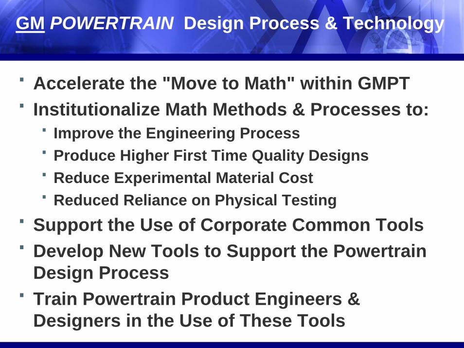
· Accelerate the "Move to Math" within GMPT · Institutionalize Math Methods & Processes to:
· Improve the Engineering Process· Produce Higher First Time Quality Designs· Reduce Experimental Material Cost· Reduced Reliance on Physical Testing
· Support the Use of Corporate Common Tools· Develop New Tools to Support the Powertrain
Design Process · Train Powertrain Product Engineers &
Designers in the Use of These Tools

How We Design Engines with Large Assemblies –System Design Process
· System Design Approach· System Design Driven with a Live Powertrain
Assembly Structure (PAS)· TcAE Data Management Leveraged· Emphasis on Common Methods & Processes· Focus on Teamwork through Leadership

Powertrain Assembly Structure (PAS)

AHS54443/003-IA ACCESSORY DRIVE SYSTEM
· Bullet 1· Bullet 2

12595401/004-TENSIONER ASM-DRV BELT
· Bullet 1· Bullet 2
Need for Arrangements in the Design Process
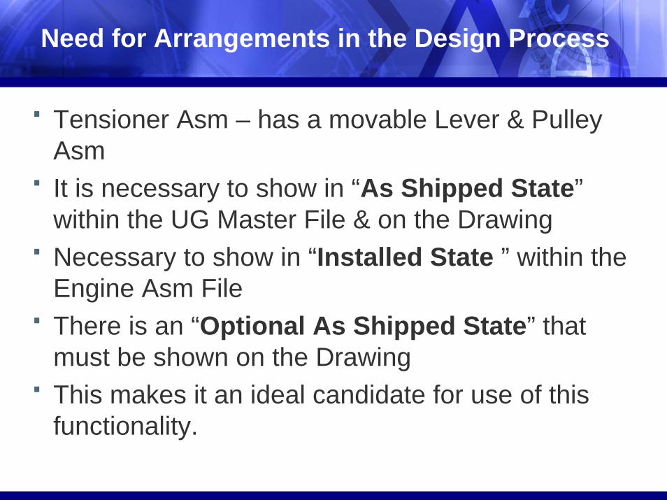
· Tensioner Asm – has a movable Lever & Pulley Asm
· It is necessary to show in “As Shipped State”within the UG Master File & on the Drawing
· Necessary to show in “Installed State ” within the Engine Asm File
· There is an “Optional As Shipped State” that must be shown on the Drawing
· This makes it an ideal candidate for use of this functionality.

Requirements for Arrangements
· There must be an assembly (since Arrangementsmerely Repositions the components).
· It is still necessary to create ALTREPs for those parts that have DEFORMATION upon assembly
· Every part file has an Arrangement and a Default · Important to save the part file with the intended
Arrangement· The Default Arrangement should be the one that
defines the UGMaster

Process Relies on Three Key NX Technologies
· Use of Arrangements to create the alternative positions
· Use of WAVE Geometry Linker to "link" the "Installed State" Tensioner Asm to the ALTREP of the Accessory Drive Belt for a particular Accessory Drive System
· Use of Exploded Views within Drafting to enable the depiction of multiple Arrangements on the same Drawing

Creating Arrangements
· The first order of business, in this case, is to create a “true” assembly structure.

Creating a “True” Assembly Structure.
· Bullet 1· Bullet 2

“True” Assembly Structure Created
· Assembly Structure after New Components Created

Creating the Arrangements
· System creates your first arrangement when you add or create the first component · Add the column “Arrangement” to the Assembly Navigator· Create all new Arrangements by copying the first· Rename each Arrangement· Make each Arrangement the “Active Arrangement”and reposition the components to suit that Arrangement· Make the Default Arrangement Active and save the part file

Positioning Components-Use of Wavelinking
· ALTREP (Installed State) of the Accessory Drive Belt is driven by a completely constrained Sketch
· All pulley locations are constrained, except for the position ofthe movable Tensioner Pulley
· Tensioner Pulley location is determined by the belt length chosen for a particular Accessory Drive System
·

Wavelinking ALTREP Sketch into Tensioner ASM
· IA ACCESSORY DRIVE SYSTEM the “Displayed Part”, Tensioner Asm the “Work Part”
· Make “LT8 ENGINE INSTALLED POSITION” the Active Arrangement for the Tensioner Asm
Wavelinking ALTREP Sketch into Tensioner ASM
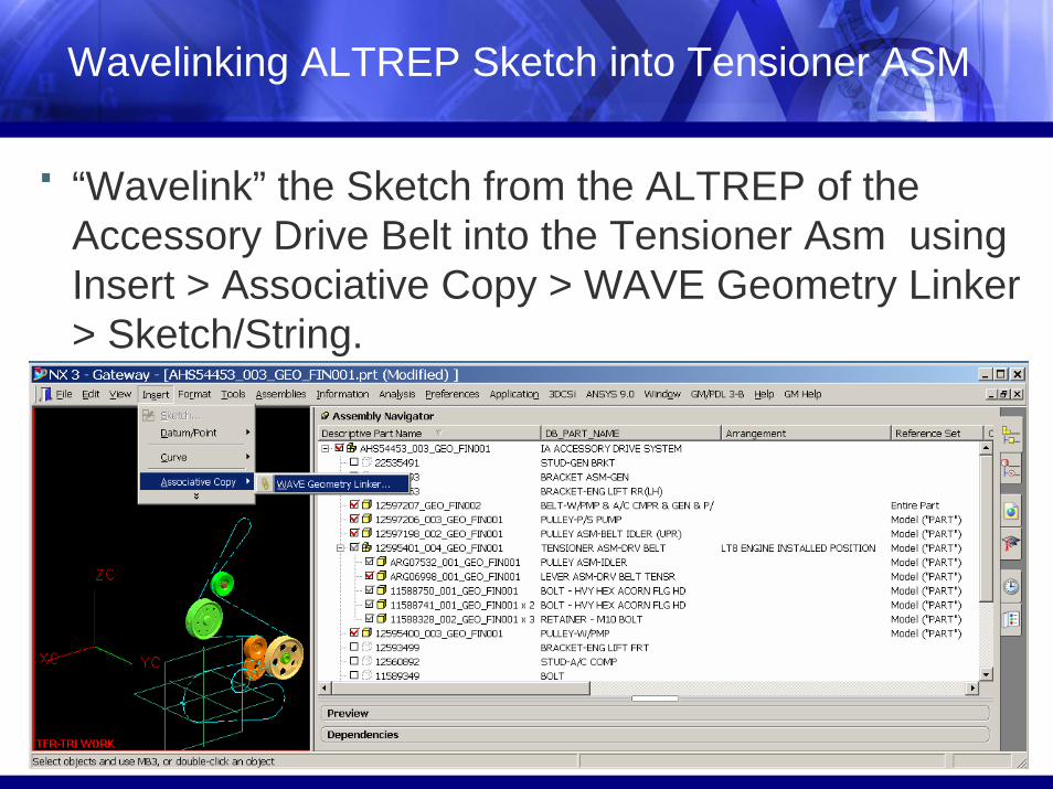
· “Wavelink” the Sketch from the ALTREP of the Accessory Drive Belt into the Tensioner Asm using Insert > Associative Copy > WAVE Geometry Linker > Sketch/String.

Tensioner Asm the “Displayed Part”
· Verify the “Linked Sketch” Feature just created using Information > Feature. Select the Sketch. Select OK or Apply.

Tensioner Asm the “Displayed Part”
· The Info Window returns the following information
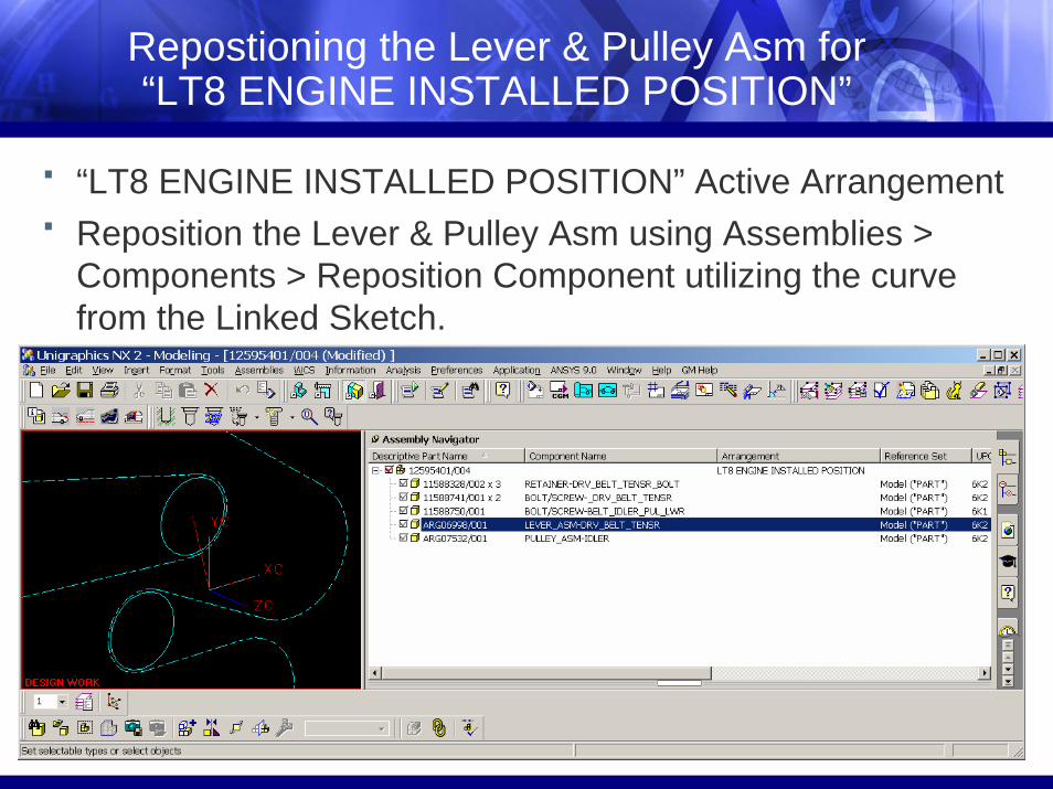
Repostioning the Lever & Pulley Asm for “LT8 ENGINE INSTALLED POSITION”
· “LT8 ENGINE INSTALLED POSITION” Active Arrangement· Reposition the Lever & Pulley Asm using Assemblies >
Components > Reposition Component utilizing the curve from the Linked Sketch.

Tensioner Asm - Other Arrangements
· The existing Arrangement was copied five more times. These were used to show other key positions in the travel and positioning of the components. They were renamed:
· (A1) WORKING RANGE START· (A2) END WORKING RANGE· (F) FREE ARM STATE · (N) NOMINAL POSITION· (OPT) AS SHIPPED STATE

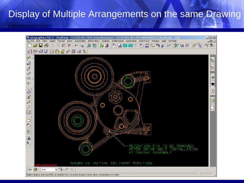
Display of Multiple Arrangements on the same Drawing
· Requires Arrangements in the Drawing file.· Each “Drawing Arrangement” will use a unique Arrangement of the Tensioner Asm(an Arrangement of an Arrangement)· “Drawing Arrangement 1” uses “(M) AS SHIPPED STATE” Arrangement · “Drawing Arrangement 2” uses “(OPT) AS SHIPPED STATE” Arrangement· An “Exploded View” is used to capture the “(OPT) AS SHIPPED STATE” since Exploded Views are arrangement-specific
Display of Multiple Arrangements on the same Drawing

Display of Multiple Arrangements on the same Drawing

Drawing Arrangement 1
· In the Drawing file, go to the Modeling Application. Rename the default Arrangement to “Drawing Arrangement 1”. Use the “(M) AS SHIPPED STATE” Arrangement of the Tensioner Asm

Drawing Arrangement 2
· Copy “Drawing Arrangement 1” and rename it “Drawing Arrangement 2 Use the “(OPT) AS SHIPPED STATE” Arrangement of the TensionerAsm

Creating the “Exploded View”
· With Drawing Arrangement 2 active, orient the view in Modeling to correctly represent the view required on the Drawing
· Select View > Operation > Save-As, enter “OPT SHIPPING STATE” for the name of the view
· To create the Exploded view, select Assemblies > Exploded Views > Create Explosion. Enter “(OPT) AS SHIPPED STATE” for the name of the Explosion

Creating the “Exploded View”

Placing the Exploded View on the Drawing
· Switch the active arrangement back to “Drawing Arrangement 1”
· Note that the “OPT SHIPPING STATE (EXPLODED)” view retains its “snapshot” of the alternate positions, since Exploded Views are arrangement-specific
· Return to the Drafting Application. Add the “OPT SHIPPING STATE (EXPLODED)” view to the Drawing using the Import View option.
· Remember to have “Drawing Arrangement 1” as the active arrangement prior to performing Update Views

"Installed State" within the Engine Asm File
· Once the Arrangements are created within the TENSIONER ASM, it is a simple matter to edit the IA ACCESSORY DRIVE SYSTEM. Make the “LT8 ENGINE INSTALLED POSITION” the active arrangement and file the IA

Next Steps
· We would like the functionality to MATE each of the Arrangements uniquely within the TensionerAsm file to have a truly “Linked” system.
· Datums would be created from the Linked Sketch· Each Arrangement would then be Mated· In this manner, the entire system could be driven
by one Sketch

Questions