GEOTECHNICAL ENGINEERING STUDY - RM Dudley Construction · gessner engineering civil structural...
30
GESSNER ENGINEERING CIVIL STRUCTURAL GEOTECHNICAL LAND SURVEYING CONSTRUCTION MATERIALS TESTING Mr. Steven Craney Goree Architects, Inc. 4710 Bellaire Boulevard, Suite 105 Bellaire, Texas 77401 September 14, 2015 GEOTECHNICAL ENGINEERING STUDY Tomball Ford Remodel 22702 Tomball Parkway Tomball, Texas Gessner Engineering Job No.: 15-0747
Transcript of GEOTECHNICAL ENGINEERING STUDY - RM Dudley Construction · gessner engineering civil structural...

GESSNER ENGINEERING
CIVIL STRUCTURAL GEOTECHNICAL LAND SURVEYING CONSTRUCTION MATERIALS TESTING
Mr. Steven Craney
Goree Architects, Inc.
4710 Bellaire Boulevard, Suite 105
Bellaire, Texas 77401
September 14, 2015
GEOTECHNICAL ENGINEERING STUDY
Tomball Ford Remodel
22702 Tomball Parkway
Tomball, Texas
Gessner Engineering Job No.: 15-0747

COLLEGE STATION 979 680 8840 • BRENHAM 979 836 6855 • FORT WORTH 817 405 0774 • SAN ANTONIO 210 305 4792
2501 Ashford Drive, Suite 102 / College Station, Texas 77840 • Fax 979 680 8841 • www.gessnerengineering.com
CIVIL STRUCTURAL GEOTECHNICAL LAND SURVEYING CONSTRUCTION MATERIALS TESTING
September 14, 2015
Mr. Steven Craney
Goree Architects, Inc.
4710 Bellaire Boulevard, Suite 105
Bellaire, Texas 77401
Re: Geotechnical Engineering Study
Tomball Ford Remodel
22702 Tomball Parkway
Tomball, Texas
Gessner Engineering Job No.: 15-0747
Dear Mr. Craney:
This report conveys our geotechnical engineering study conducted for the proposed Tomball Ford
Remodel located in Tomball, Texas. The following report contains our design recommendations and
considerations based on our understanding of the information provided to us. The purpose of this
study was to drill borings within the proposed building footprint, to perform laboratory testing to
classify and characterize surface conditions, and to prepare an engineering report presenting
foundation design and construction recommendations for the proposed addition. We trust that this
report is responsive to your project needs. Please contact us if you have any questions or if we can be
of further assistance.
We are happy to be of service to you on this phase of the project, and look forward to the opportunity
to provide additional geotechnical engineering services, structural services, civil engineering services
and construction materials testing services as the project progresses.
Sincerely,
GESSNER ENGINEERING, LLC F-7451
Kristina M. Farris, E.I.T.
Matthew J. Robbins, P.E.
Copies Submitted:
Mr. Steven Craney

GESSNER ENGINEERING
CIVIL STRUCTURAL GEOTECHNICAL LAND SURVEYING CONSTRUCTION MATERIALS TESTING
CONTENTS
CONTENTS ................................................................................................................................................. 3
INTRODUCTION ........................................................................................................................................ 5
PROJECT DESCRIPTION .......................................................................................................................... 5
SCOPE OF SERVICES ............................................................................................................................... 5
SITE INVESTIGATION PROCEDURES ................................................................................................... 6
LABORATORY TESTING .......................................................................................................................... 7
SITE CONDITIONS .................................................................................................................................... 9
Site Geology .................................................................................................................................. 9
Surface Conditions ...................................................................................................................... 9
Subsurface Conditions ............................................................................................................... 9
Groundwater Conditions .......................................................................................................... 10
ENGINEERING RECOMMENDATIONS ................................................................................................ 11
Stiffened Slab-on-Grade ................................................................................................................. 11
Conventionally Reinforced System ....................................................................................... 12
Deep Foundations ............................................................................................................................ 14
Temporary Casing ..................................................................................................................... 14
Additional Considerations ............................................................................................................. 14
Earthwork ........................................................................................................................................... 15
Foundation Earthwork .............................................................................................................. 15
Site Fill .......................................................................................................................................... 16
Utility Trench Fill ........................................................................................................................ 16
Drainage ............................................................................................................................................. 16
Pavement Recommendations ....................................................................................................... 17
Subgrade Conditions ................................................................................................................ 17
Design Information .................................................................................................................... 17
Rigid Pavement .......................................................................................................................... 17
Portland Cement Concrete ...................................................................................................... 18
Flexible Pavement ..................................................................................................................... 19
Garbage Dumpsters .................................................................................................................. 19
Sidewalks .................................................................................................................................... 19
Flexible Base Course................................................................................................................. 19
Asphaltic Concrete Surface Course....................................................................................... 19
Pavement Earthwork ................................................................................................................. 19
Pavement Drainage Considerations ..................................................................................... 20
Other Issues ..................................................................................................................................... 20
Construction Materials Testing ................................................................................................... 20
General Comments .......................................................................................................................... 22
Limitations ......................................................................................................................................... 22
APPENDIX ................................................................................................................................................. 23

CONTENTS
GESSNER ENGINEERING 4
CIVIL STRUCTURAL GEOTECHNICAL LAND SURVEYING CONSTRUCTION MATERIALS TESTING
RECOMMENDATIONS SUMMARY....................................................................................................... 24

GESSNER ENGINEERING 5
CIVIL STRUCTURAL GEOTECHNICAL LAND SURVEYING CONSTRUCTION MATERIALS TESTING
Introduction
This report briefly describes the procedures
utilized during this study and presents the
results of our geotechnical engineering study
for the proposed Tomball Ford Remodel,
located in Tomball, Texas. Gessner
Engineering was authorized to provide the
subsurface investigation and report for this
project by Mr. Steven Craney on August 24,
2015.
Project Description
The project consists of the proposed
construction of an addition to the existing
Tomball Ford Dealership located at 22702
Tomball Parkway in Harris County, Texas. We
understand that the proposed single-story
addition will have a footprint of approximately
7,636 square feet (sf). It is our understanding
at the time of our study, site grading plans
and proposal structural loads were not
available.
Scope of Services
The Texas Section of the American Society of
Civil Engineers defines an engineered
foundation as one that includes a
geotechnical engineering investigation. To
act as this first phase of an engineered
foundation, our scope of work for this project
consisted of:
1. Drilling 3 test bore holes at the selected
location within the project site to evaluate the
subsurface arrangement of strata and
groundwater conditions.
2. Performing geotechnical laboratory tests
on recovered samples to evaluate the
physical and engineering properties of the
strata observed.
3. Engineering analysis to develop design
and construction recommendations with
respect to:
• Site, subgrade, and fill preparation; and
• Foundation design and construction.
Project Location
GESSNER ENGINEERING 6
CIVIL STRUCTURAL GEOTECHNICAL LAND SURVEYING CONSTRUCTION MATERIALS TESTING
Bore Holes:
3 Bore Holes
Depth: 20 feet
SITE INVESTIGATION PROCEDURES
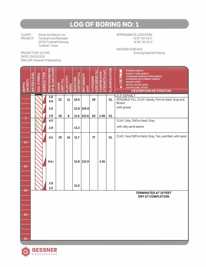
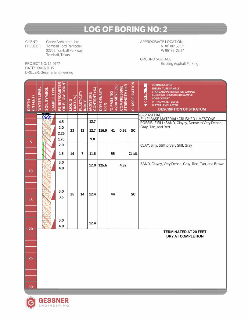
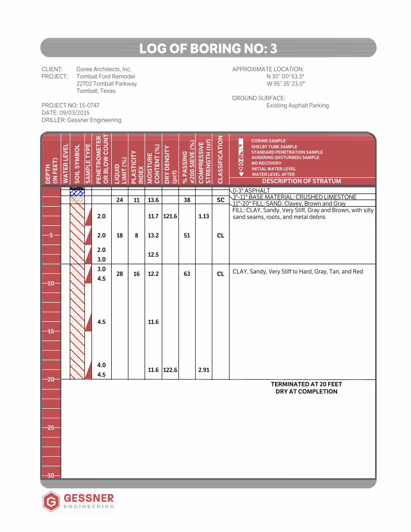
Subsurface conditions at the site were evaluated by 3 borings drilled at the locations shown on the Project Layout in the Appendix. These locations
are approximate and distances were measured using a hand-held, recreational-grade GPS locator; tape; angles; pacing; etc. On September 3, 2015, the borings were drilled to a depth of approximately 20 feet below the existing ground surface using a track-mounted drill rig. The log of bore holes, presenting the subsurface soil descriptions, type of sampling used, laboratory results, and additional field data, is presented in the Appendix. The Symbol Key Sheet, which defines the terms and descriptive symbols used on the log, is also provided in the Appendix.
Soil samples were generally recovered using thin-walled, open-tube samplers (Shelby tubes). This type of sampling produces samples described as relatively undisturbed, which are obtained for laboratory testing. Samples were taken continuously for the first 10 feet in 2 foot increments. Below 10 feet, samples were taken at 5 foot intervals to the termination of the bore hole.
Pocket penetrometer tests were performed on samples of cohesive soils in the field to serve as a general measure of consistency and to give a relative measure of the strength of the sample.
All samples were removed from samplers in the field, visually classified, and appropriately sealed in sample containers to preserve their in situ moisture contents.
Throughout the report, the soils are referred to in terms used to describe their consistency. The term consistency refers to the degree of adhesion between the soil particles and to the resistance offered against forces that tend to deform or rupture the soil aggregate. The consistency of clays and other cohesive soils is usually described as very soft, soft, firm, stiff, very stiff, and hard. The correlation between the pocket penetrometer results and these consistency terms are provided on the Figure, “Symbols and Terms used on Boring Logs” in the Appendix. Additional consistency terms used on cohesive soils are plastic, lean, and fat. As a soil approaches the characteristics of a clay soil, the greater the variety of states of consistency in which it may be found. A plastic soil changes physical properties depending upon the moisture content of the soil. The degree of plasticity is sometimes expressed by the terms fat and lean. Lean clay is only slightly plastic; whereas fat clay has a high plasticity.

GESSNER ENGINEERING 7
CIVIL STRUCTURAL GEOTECHNICAL LAND SURVEYING CONSTRUCTION MATERIALS TESTING
LABORATORY TESTING
Samples obtained during the field program
were visually classified in the laboratory by a
geotechnical engineer or their representative.
A testing program was conducted on
selected samples in accordance with the
ASTM Standard Test Procedures, as directed
by the geotechnical engineer, to aid in
classification and evaluation of engineering
properties required for analysis.
The laboratory testing program for this
project included sieve analyses, moisture
contents, Atterberg limits, unit weights, and
unconfined compressive strengths.
The sieve analyses were performed by
passing the sample through a series of sieves
to classify the soil based on their particle size.
This allows a determination of the type of
soils, distribution of the particle sizes and the
interaction between the particles. The sieve
analysis procedure is outlined in ASTM C136.
Sieves used for this test include a series of
screens of various sizes to determine the
amount of various particle sizes in a sample.
The moisture content tests were performed in
accordance with ASTM D2216 by placing a
sample into an oven with a constant
temperature and comparing the mass before
oven drying to the mass after oven drying.
Changes in the moisture content have a
significant effect on the behavior of plastic
soils. Variations in the moisture content from
the state observed during investigation to the
moisture content from the state observed
during construction can result in expansive
soil related movements. If the moisture
content of the soil increases after
construction, for example, the soil can induce
uplift forces on the structure it is supporting.
The structure of clay consists of a random
arrangement of flat plates. Edges of the
particles are positively charged, and the face
is negatively charged. The negative charges
on the face of the clays bond with positive
water ions in the soil, causing a volumetric
change resulting in expansion of the soils.
This water may be released with the
application of pressure from load,
evaporation, or suction from gravity or
vegetation. The specific chemical makeup of
the various clays causes them to have a
stronger or weaker ability to bond with water.
In order to relate moisture content and soil
consistency, Atterberg limit tests were
performed on the samples in accordance with
ASTM D4318. The Atterberg limit test is
comprised of 2 separate tests: plastic limit
and liquid limit. The plastic limit test
determines the moisture content of the soil in
its dry state while the liquid limit test
determines the moisture content as the soil
nears a liquid state.
The plastic limit is described as the moisture
content of the soil where it transitions
between brittle and plastic behavior. This
point is determined by rolling the samples in
threads 1/8 inch (3 mm) in diameter to the
point at which they begin to crack and/or
crumble.
The liquid limit describes the moisture
content of the soil where it transitions
between plastic and liquid behavior. In
conducting this test, the sample is placed in
the Casagrande cup or liquid limit device. A
standard grooving tool is used to create a

GESSNER ENGINEERING 8
CIVIL STRUCTURAL GEOTECHNICAL LAND SURVEYING CONSTRUCTION MATERIALS TESTING
gap in the center of the sample 0.53 inches
(13.5 mm) in width. The cup is then dropped
repeatedly onto the hard rubber base at a rate
of 120 blows per minute. The liquid limit is the
moisture content at which the groove closes
at 25 blows.
The plasticity index is the difference between
the liquid limit and the plastic limit and
provides a description of the moisture states
a soil can experience. The plasticity index is
an indicator of the potential for expansion or
contraction of the soil.
Unit weights were determined by the ratio of
the weight to given volume of a sample in
accordance with ASTM D7263. Dry density
measurements are useful to determine the
degree of soil compaction, void ratio, and
porosity.
The unconfined compressive strength of the
soil can be used to estimate the shear
strength of cohesive soils. Unconfined
compression tests are a direct method to
determine the strength of cohesive soils
under unconfined conditions. Tests were
performed in accordance with ASTM
D2166 by placing a cylindrical soil sample
with no confinement on the testing platform
and applying a compressive load until it fails.
The load is applied fairly rapidly, thus
producing undrained conditions.
In an undrained condition the pore water
moves slowly through the sample, and
excess pore pressures develop. Generally,
structures are constructed and loads
imposed on the soil more quickly than the
rate of drainage of the soils.
Results of the laboratory tests are presented
on the Log of Bore Holes in the Appendix and
are discussed in the following sections.
Samples will be retained in our laboratory for
30 days after submittal of this report.
GESSNER ENGINEERING 9
CIVIL STRUCTURAL GEOTECHNICAL LAND SURVEYING CONSTRUCTION MATERIALS TESTING
SITE CONDITIONS
Site Geology
Major soil formations provide information
with regards to the depth and magnitude of
the conditions, as well as anticipated features
of the soils in this area. This information
provides typical data for the area. While it is
valid as a general reference, it does not
provide data accurate enough to replace site
specific engineering analysis.
The site is located in the Lissie Formation of
the Pleistocene Age in the Quaternary Era as
indicated on the Geologic Atlas of Texas,
Beaumont Sheet as published by the
University of Texas at Austin. The Lissie
formation is composed of clay, silt, sand, and
very minor siliceous gravel of granule and
small pebble size. The upper part of this
formation is calcareous, has concretions of
calcium carbonate, iron oxide, and iron-
manganese oxides are also common in zone
of weathering. The surface is fairly flat and
featureless except of numerous rounded
shallow depressions and pimple mounds.
The lower part consists of clay, silt, sand, and
minor amount of gravel. The gravel is slightly
coarser than in the upper part, and the lower
portion is also noncalcareous with more iron
oxide concretions than the upper part. This
formation is approximately 200 feet thick.
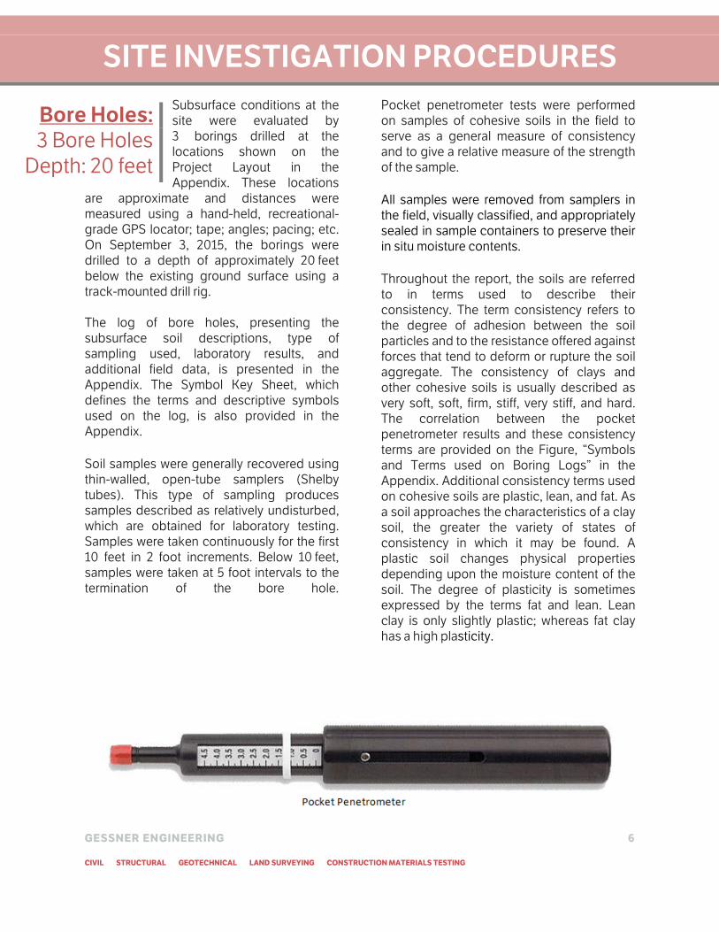
Surface Conditions
Based on visual observations, the area of the
proposed addition is located on an existing
asphalt pavement next to an existing Ford
Dealership. The site consists of a gentle slope
with an elevation difference of approximately
2 feet across the site.
Site Picture
Subsurface Conditions
The subsurface arrangement of strata at the
site was evaluated from our field and
laboratory programs. In general, the soil
stratigraphy from the surface to 1 foot
indicated existing asphalt pavement and
base material, followed by possible fill
consisting of sandy clay and clayey sand from
1 foot to 5 feet, then silty clay and clay from
5 feet to 8 feet, followed by clay, clayey sand,
and sandy clay to the termination of the bore
hole at approximately 20 feet below existing
grade.
These soils generally exhibit a low to
moderate potential for volumetric change due
to moisture variations, as indicated by the
measured plasticity indices (PI) which are
presented in Table 1. The table (Table 1) also
contains the in situ moisture contents that
correspond to the plastic limits found in each
bore hole. These moisture contents indicate
that the soils were generally wet at the time of
sampling. Moisture contents are compared to
plastic limits to evaluate the conditions within
the plastic state for the particular soil, as
opposed to absolute values of moisture
content.
During the procurement of subsurface
samples, pocket penetrometer tests were

GESSNER ENGINEERING 10
CIVIL STRUCTURAL GEOTECHNICAL LAND SURVEYING CONSTRUCTION MATERIALS TESTING
performed upon each undisturbed soil sample. Pocket penetrometers provide an estimate of soil strength by pressing a spring loaded piston a specified depth into the soil sample. In addition, unconfined compression tests were performed on selected samples in the laboratory to supplement the field results. The shear strength based on unconfined compressive tests are included in Table 1 below.
Groundwater Conditions
The bore holes were dry augered to their completed depth in an attempt to observe groundwater conditions. No groundwater was observed in the bore holes at the time of the drilling. We should note that groundwater at the site may occur in the form of “perched” water traveling along pervious seams or layers within the soils. The frequency of such groundwater is expected to increase during and soon after periods of wet weather. The direction of flow of subsurface moisture is unknown and many times will differ from the surface topography. Caution should be taken when constructing in wet seasons and all water accumulated during construction shall be removed prior to concrete placement.
Table 1: Engineering Properties of Each Soil Strata
Approximate
Depth (feet) Strata PI Range
Moisture Content
Range (%)
Shear Strength
(tsf)
0-1 Asphalt Paving and Fill -- -- --
1-5 Clayey Sand (SC),
Sandy Clay (CL) 8-12 1% Dry to 3% Wet 0.92-1.40
5-8 Silty Clay (CL-ML),
Sandy Clay (CL) 7-8 2% to 5% Wet --
8-20 Clay (CL), Sandy Clay
(CL), Clayey Sand (SC) 14-16 2% Dry to 2% Wet 2.45-4.32
All samples were returned to our laboratory in Brenham, Texas. Samples not tested in the
lab will be stored for a period of thirty (30) days subsequent to submittal of this report and
will be discarded after this period, unless Gessner Engineering is notified otherwise.
Whenever possible, samples are used to fill subsequently drilled bore holes, or used to fill
washed out areas or holes to prevent adding unnecessary waste to landfills.
GESSNER ENGINEERING 11
CIVIL STRUCTURAL GEOTECHNICAL LAND SURVEYING CONSTRUCTION MATERIALS TESTING
ENGINEERING RECOMMENDATIONS
The following recommendations are based upon the data obtained in our field and laboratory
programs, information provided to Gessner Engineering by the client including scale of the project
and use, and our experience with similar subsurface and site conditions and the proposed
construction methods. Often the use of the facility dictates that the foundation will support closely
spaced walls and brittle finishes. The extensive use of brittle finishes throughout typical office
buildings and homes requires that the foundation be sufficiently rigid to limit deflection which
would crack these finishes. By contrast, the use of some facilities requires flexibility in the
foundation system. Retail centers, for instance, require frequent remodeling due to tenant changes,
and the client may need to cut the floor slab to relocate plumbing.
In addition, the scale of the project affects the geotechnical recommendations. For relatively small
facilities, it is more cost effective and successful to stiffen a foundation to perform on the underlying
expansive soils. Projects with large footprints can economically be constructed through extensive
preparation of the subgrade soils to provide suitable conditions for a less stiff and consequently
less expensive foundation. Subgrade treatment can include chemical stabilization, removal and
replacement, or other methods to improve the in situ soil characteristics.
Gessner Engineering makes reasonable assumptions regarding these recommendations based on
client data. The cost effectiveness of the foundation system may be affected by numerous items
including but not limited to: construction cost variations, the availability of fill, site topography, and
presence of groundwater.
This report provides recommendations to help mitigate the effects of soil expansion and
contraction. However, even if these procedures are followed, movement and cracking in the
structure should be anticipated. The potential for material cracking and other damage, such as
unlevel floor slabs, will increase if modifications at the site during or after construction results in
excessive wetting or drying of the expansive soils. Eliminating the risk of movement and distress
may not be feasible, but it may be possible to further reduce the risk of movement if significantly
more expensive measures are used during construction. Gessner Engineering would be pleased to
discuss other construction alternatives upon request.
Deciding the type of foundation system is a process that should involve the owner, architect,
contractor/builder, and engineer. The owner and architect should be aware of the potential risks
and cost implications of the selected foundation system. The type of foundation may affect the
selection of finishes, joint locations in walls, and joint locations in masonry.
Given the scale and use of the facility in the soil conditions located at this site, a stiffened slab-on-
grade foundation system is recommended to support the proposed structure. If there are many
concentrated loaded, or if the client so desires, the stiffened slab may be supported on piers.
Stiffened Slab-on-Grade A stiffened slab-on-grade, also known as a waffle slab or modified mat foundation, consists of a
slab stiffened with beams spanning across the foundation in each direction. Stiffened slab-on-
grade foundations are appropriate for foundations on expansive soils which are sensitive to
deflection. Grade beams in these foundations should extend from edge to edge across the slab.
The network of grade beams is intended to create a rigid plate that moves as a unit in response to

GESSNER ENGINEERING 12
CIVIL STRUCTURAL GEOTECHNICAL LAND SURVEYING CONSTRUCTION MATERIALS TESTING
soil movement. Stiffened slab-on-grade systems can be designed as conventionally reinforced or cable post tensioned systems. A stiffened slab-on-grade can be supported on piers to help reduce structural risks associated with expansive soils, especially when the foundation will carry large concentrated loads. Similar to structural elevated foundation systems, piers are founded in soil strata deep enough to limit the magnitude of seasonal soil movement. As recommended by the Texas Branch of the American Society of Civil Engineers, piers should be isolated from a stiffened slab-on-grade foundation in expansive soils to avoid failure from uplift pressure. Even if the pier is designed for tensile forces, piers tied to the foundation system are subject to failure at the weakest point (often the slab around the pier) due to the extremely high loads swelling clays can generate beneath the slab. Properly designed and installed, piers can provide additional support for concentrated loads and minimize the movement of the foundation. Piers shall be designed in accordance with the Deep Foundation section of this report. Gessner Engineering has calculated the potential vertical rise (PVR) of the soils at this site using the Texas Department of Transportation Method Tex-124-E. The movement may be either heave or settlement depending on the changes in the moisture content. The PVR at this site is calculated to be approximately on the order of one inch or less, assuming an active zone of 10 feet. Due to assumptions and generalities required for the calculation of the potential vertical movement, it should only be taken as an approximation. We should note that moisture variations in the subgrade soils due to poor drainage, perched water in pervious layers, leakage of utilities, etc. could induce volumetric changes resulting in movements which are in excess of those estimated by the PVR procedure. The parameters for the foundation design presented here are provided for the methods recommended by the Texas Branch of the American Society of Civil Engineers. Should the design engineer require additional parameters, please contact Gessner Engineering.
Conventionally Reinforced System
The primary role of steel reinforcement in reinforced concrete is to carry the tensile forces due to flexure of the beams. Concrete has high compressive strength but lacks tensile strength. The conventionally reinforced stiffened slab-on-grade uses steel reinforcement in the grade beams to create the necessary stiffness in the foundation. Increasing the grade beam depth and size of reinforcement and decreasing the beam spacing provide additional stiffness for more expansive soils. Presented below are the design parameters for the Building Research Advisory Board (B.R.A.B.) design method and the Wire Reinforcement Institute (W.R.I.) design method based upon the subsurface conditions observed at this project location. These methods are essentially empirical design techniques and the parameters provided are based on our interpretation of the project soil borings and criteria published in the B.R.A.B. design manual and the W.R.I. design manual. Based on the existing soil, the effective plasticity index is calculated at 20 which indicates a moderate expansion potential. A value of 2,750 pounds per square foot (psf) may be used as the resulting allowable bearing pressure for the soils at 1 to 3 feet below ground surface with a properly prepared building pad. Other measures recommended to reduce moisture infiltration into the

GESSNER ENGINEERING 13
CIVIL STRUCTURAL GEOTECHNICAL LAND SURVEYING CONSTRUCTION MATERIALS TESTING
subgrade are presented later in this subsection and in the “Drainage” subsection. The effective design parameters after the recommended earthwork is performed are presented in the table below.
Design Effective Plasticity Index 20
Allowable Bearing Capacity (psf) 2,750
Climatic Rating 25
Soil Support Index (SSI) 0.95
Table 2: B.R.A.B. or W.R.I. Design Parameters We recommend that grade beams extend at least 12 inches below final grade into properly
compacted earth. This recommendation is to reduce surface water migration below the foundation elements and to develop proper bearing of the grade beams. According to section 1809 of the International Building Code, the foundation is required to bear 12 inches below the adjacent soil. The grade beam width and depth should be properly evaluated by the structural engineer. Grade beams may be thickened and widened at column locations to serve as spread footings to support concentrated loads. The amount of total and differential settlement of the proposed site is anticipated to be minimal if the design requirements are precisely followed as stated in this report. Calculated bearing capacities for this site should be sufficient to provide this performance. For a stiffened slab-on-grade foundation, we highly recommend that measures be taken whenever practical to increase the tolerance of the addition to post-construction foundation movements. An example of such measures would be to provide frequent control joints for masonry/brick/stucco veneer exteriors, if any, to control cracking across such walls and concentrate movement along the joints. Care should be taken in all foundation systems to provide adequate drainage around the structure and prevent ponding of runoff adjacent to the foundation. In addition, systems that extend from the building into the shallow soils such as plumbing should be designed to accommodate the movement of the shallow soils. Subgrade for stiffened slab-on-grade foundation system shall be prepared in accordance with the foundation portion of the soil preparation section of this report. Some of the native soils at this site are sandy and cohesionless in nature. Consequently, these soils will be very susceptible to small changes in moisture content and to disturbance from foot traffic during the placement of steel reinforcement in beam trenches, particularly in periods of inclement weather. Disturbances in such foot traffic and from the accumulation of excess water can result in losses of bearing capacity and increased settlement. If inclement weather is anticipated at the time of construction, consideration should be given to protecting the bottoms of beam trenches by placing a thin mud mat (layer of flowable fill or lean concrete) at the bottom of trenches immediately following excavation. This will reduce disturbance from foot traffic and will impede the infiltration of surface water. The side slopes of beam trench excavation may also need to be flattened to reduce slouching in cohesionless soils. All necessary precaution should be implemented to protect open excavation from the accumulation of surface water runoff and rain.
GESSNER ENGINEERING 14
CIVIL STRUCTURAL GEOTECHNICAL LAND SURVEYING CONSTRUCTION MATERIALS TESTING
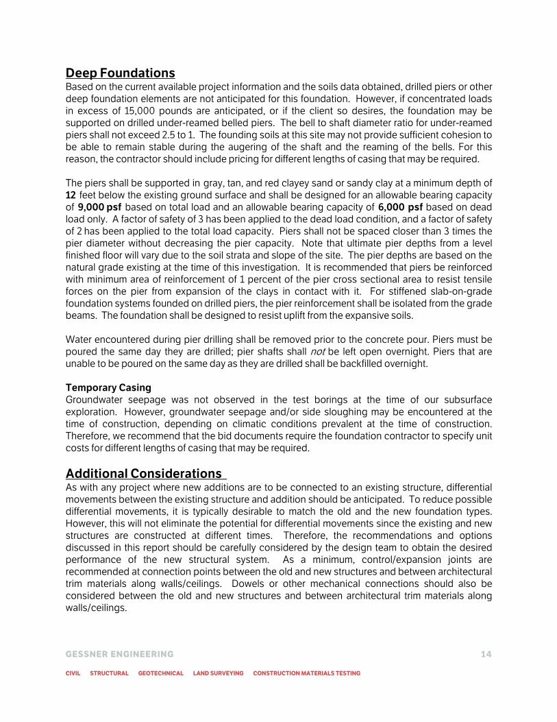
Deep Foundations Based on the current available project information and the soils data obtained, drilled piers or other deep foundation elements are not anticipated for this foundation. However, if concentrated loads in excess of 15,000 pounds are anticipated, or if the client so desires, the foundation may be supported on drilled under-reamed belled piers. The bell to shaft diameter ratio for under-reamed piers shall not exceed 2.5 to 1. The founding soils at this site may not provide sufficient cohesion to be able to remain stable during the augering of the shaft and the reaming of the bells. For this reason, the contractor should include pricing for different lengths of casing that may be required. The piers shall be supported in gray, tan, and red clayey sand or sandy clay at a minimum depth of 12 feet below the existing ground surface and shall be designed for an allowable bearing capacity of 9,000 psf based on total load and an allowable bearing capacity of 6,000 psf based on dead load only. A factor of safety of 3 has been applied to the dead load condition, and a factor of safety of 2 has been applied to the total load capacity. Piers shall not be spaced closer than 3 times the pier diameter without decreasing the pier capacity. Note that ultimate pier depths from a level finished floor will vary due to the soil strata and slope of the site. The pier depths are based on the natural grade existing at the time of this investigation. It is recommended that piers be reinforced with minimum area of reinforcement of 1 percent of the pier cross sectional area to resist tensile forces on the pier from expansion of the clays in contact with it. For stiffened slab-on-grade foundation systems founded on drilled piers, the pier reinforcement shall be isolated from the grade beams. The foundation shall be designed to resist uplift from the expansive soils. Water encountered during pier drilling shall be removed prior to the concrete pour. Piers must be poured the same day they are drilled; pier shafts shall not be left open overnight. Piers that are unable to be poured on the same day as they are drilled shall be backfilled overnight. Temporary Casing
Groundwater seepage was not observed in the test borings at the time of our subsurface
exploration. However, groundwater seepage and/or side sloughing may be encountered at the time of construction, depending on climatic conditions prevalent at the time of construction. Therefore, we recommend that the bid documents require the foundation contractor to specify unit costs for different lengths of casing that may be required.
Additional Considerations As with any project where new additions are to be connected to an existing structure, differential movements between the existing structure and addition should be anticipated. To reduce possible differential movements, it is typically desirable to match the old and the new foundation types. However, this will not eliminate the potential for differential movements since the existing and new structures are constructed at different times. Therefore, the recommendations and options discussed in this report should be carefully considered by the design team to obtain the desired performance of the new structural system. As a minimum, control/expansion joints are recommended at connection points between the old and new structures and between architectural trim materials along walls/ceilings. Dowels or other mechanical connections should also be considered between the old and new structures and between architectural trim materials along walls/ceilings.

GESSNER ENGINEERING 15
CIVIL STRUCTURAL GEOTECHNICAL LAND SURVEYING CONSTRUCTION MATERIALS TESTING
Earthwork: Stiffened Slab-on-Grade
• Remove 1 foot of
existing material
• Replace with 1 foot of
compacted select fill
Should excavations adjacent to existing structures be required, precautions should be taken not to undermine or damage existing grade beams, footings, and/or utility lines.
Earthwork During earthwork, best practices shall be applied to limit erosion and pollution by sedimentation. At all times, the contractor shall work to maintain natural drainage and prevent the accumulation of runoff. To achieve the required moisture content, the following recommendations are included as an aid to contractors. Where subgrade or layer of soil material requires moisture before compaction, uniformly apply water to surface of subgrade. Remove and replace, or scarify and air dry soil material that is too wet to permit compaction to specified density. Soil material that has been removed because it is too wet to achieve compaction may be stockpiled or spread and allowed to dry. Assist drying by discing, harrowing or pulverizing until moisture content is reduced to a satisfactory value. Alternate methods to achieve the end result of specified moisture content and compaction may also be used. Four different methods may be utilized to successfully compact the soil. They include the processes of static weight, kneading action, impact, or vibration. The soil must be compacted using a compactor in accordance with the ASTM standards. A compactor is required to compact the soil to such a large degree. Track equipment such as bull dozers apply pressure across a large surface area and are therefore limited in their capabilities compared to a compactor. If the select fill is not compacted properly, the fill material and structures constructed on it are subject to significant settlement. Foundation Earthwork
For stiffened slab-on-grade at this site, it is recommended that a minimum of 1 foot of existing material be removed and minimum of
1 foot of select fill be compacted in place to form a level building pad. If the Stratum I gray and brown clayey sand is processed of roots, vegetation, and deleterious materials, it may be used as select fill provided that it meets the select fill requirements in the following paragraph. The building pad shall extend a minimum of 5 feet from the edge of the site footprint in all directions. Select fill shall slope away at an angle that allows for proper drainage. Refer to the Drainage section of the report for more details. Select fill to be utilized beneath the stiffened slab-on-grade limits should consist of a low plasticity clayey soil with a plasticity index between 5 and 20, a maximum gravel content (percentage retained on No. 4 sieve) of 40 percent, and rocks no larger than 2 inches in their largest dimension; or a crushed limestone base material meeting the requirements of the Texas Department of Transportation (TxDOT) 2004 Standard Specifications Item 247, Type A, Grade 4. Alternatively, a low-plasticity granular fill material which does not meet these specifications may be utilized only if approved by Gessner Engineering. All structural fill should be placed on prepared surfaces in lifts not to exceed 8 inches loose measure, with compacted thickness not to exceed 6 inches. Select fill should be compacted to at least 95 percent of the Standard Proctor (ASTM D 698) density at a moisture content ranging within 2 percent of optimum moisture content for depths of 3 feet or less. If fill in excess of 3 feet is required, all structural and select fill deeper than 3 feet shall be compacted to 100 percent of Standard Proctor (ASTM D 698).

GESSNER ENGINEERING 16
CIVIL STRUCTURAL GEOTECHNICAL LAND SURVEYING CONSTRUCTION MATERIALS TESTING
Construction areas should be stripped of all vegetation, loose topsoil, surficial concrete, etc. Roots of trees to be removed within construction areas should be excavated and removed from the construction area. Once final subgrade elevation has been achieved, exposed soil subgrade areas shall be proofrolled with a 15 ton roller (minimum) or equivalent equipment as approved by the engineer to detect weak zones. Weak areas detected during the proof rolling process, as well as zones containing debris and/or organics and voids resulting from removal of tree roots, etc., should be removed and replaced with soils exhibiting similar classification, moisture content, and density as the adjacent in situ soils. Finally, the minimum amount of select fill shall be placed to evenly build up the pad. Select fill amounts may be increased to raise the building pad to the desired finished floor elevation, or to decrease the movement potential of the site. Site Fill
For site areas not below pavements or structures, general fill may be used to achieve the desired grade. General fill shall have a plasticity index no greater than 30, and shall be free of debris and organics. All general fill should be placed on prepared surfaces in lifts not to exceed 8 inches loose measure, with compacted thickness not to exceed 6 inches. General fill should be compacted to at least 92 percent of the Standard Proctor (ASTM D 698) density at a moisture content ranging within 2 percent of optimum moisture content. General fill within 5 feet of the foundation perimeter for the top foot of soil may be installed as a clay cap on fill materials to prevent migration of surface water beneath the structure. This material shall be placed as noted above, and shall have a plasticity index in excess of 30. The fill shall be free of debris and organics, and shall be placed to comply with the Drainage section of this report. Utility Trench Fill
The upper portion of utility excavations should be backfilled with properly compacted clay soils to minimize infiltration of surface water. A clay “plug” should be provided in the trench on the exterior
of the building to prevent water from gaining access along the trench to the subgrade beneath the structure. This plug shall extend 2 feet beyond the pipe face in all directions, and be a minimum of 2 feet thick.
Drainage The performance of the foundation system for the proposed addition will not only be dependent upon the quality of construction, but also upon the stability of the moisture content of the near surface soils. Therefore, Gessner Engineering highly recommends that site drainage be developed so that ponding of surface runoff near the structure does not occur. Accumulation of water near the structure foundation may cause significant moisture variations in the soils adjacent to the foundation, thus increasing the potential for structural distress. Slope adjacent to foundations is addressed in section 1803 of the International Building Code, which requires a 5 percent slope in the first 10 feet. Where sites do not allow this, the code allows drainage structures to accommodate the runoff. It should be noted that this requirement conflicts with accessibility standards, which would govern at entrances and other travel paths.

GESSNER ENGINEERING 17
CIVIL STRUCTURAL GEOTECHNICAL LAND SURVEYING CONSTRUCTION MATERIALS TESTING
Pavement Recommendations Recommendations for both flexible and rigid pavements are presented in this report. The Owner and/or design team may select either pavement type depending on the performance criteria established for the project. In general, flexible pavement systems have a lower initial construction cost as compared to rigid pavements. However, maintenance requirements over the life of the pavement are typically much greater for flexible pavements. This typically requires regularly scheduled observation and repair, as well as overlays and/or other pavement rehabilitation at approximately one-half to two-thirds of the design life. Rigid pavements are generally more durable and require less maintenance after construction. For either pavement type, drainage conditions will have a significant impact on long term performance, particularly where permeable base materials are utilized in the pavement section. Drainage considerations are discussed in more detail in a subsequent section of this report. Subgrade Conditions
We have assumed the subgrade in pavement areas will consist of recompacted on-site clays, placed and compacted as recommended in the Pavement Earthwork section of this report. Based on our experience with similar subgrade soils, we have assigned a California Bearing Ratio (CBR) value of 3.0 for use in pavement thickness design analyses. Design Information
The following recommendations were prepared assuming a 20-year design life and Equivalent Single Axle Loads (ESAL’s) of 15,000 for light duty pavements and 50,000 for heavy duty pavements. This traffic frequency is approximately equivalent to 1 and 3 tractor-trailer trucks per day for a design period of 20 years for light and heavy duty pavements, respectively. The Project
Civil Engineer should review anticipated traffic loading and frequencies to verify that the
assumed traffic loading and frequency is appropriate for the intended use of the facility.
Rigid Pavement
We recommend that rigid pavements be considered in areas of channelized traffic, particularly in areas where truck or bus traffic is planned, and particularly where such traffic will make frequent turns, such as garbage dumpsters as described in the garbage dumpsters section of this report.
For the concrete parking lots, sidewalks and drives, frequent control joints should be used to direct shrinkage cracking with a maximum joint spacing as shown in the table below. It should be noted that the pavement thicknesses listed are minimum recommendations only and are not based on a pavement system design. Expansion joints shall be placed at anticipated stress points and dowels shall be placed across these joints. The concrete section may be reinforced and designed in accordance with ACI standard practices or may be designed as a jointed system in accordance with ACI 330R-08.
Loading Concrete Thickness
(inches)
Control Joint
Maximum Spacing (feet)
Sidewalks 4 Sidewalk Width
Parking Area 5 10
Main Drives 7 14
Table 3: Rigid Pavement System Recommendations
GESSNER ENGINEERING 18
CIVIL STRUCTURAL GEOTECHNICAL LAND SURVEYING CONSTRUCTION MATERIALS TESTING
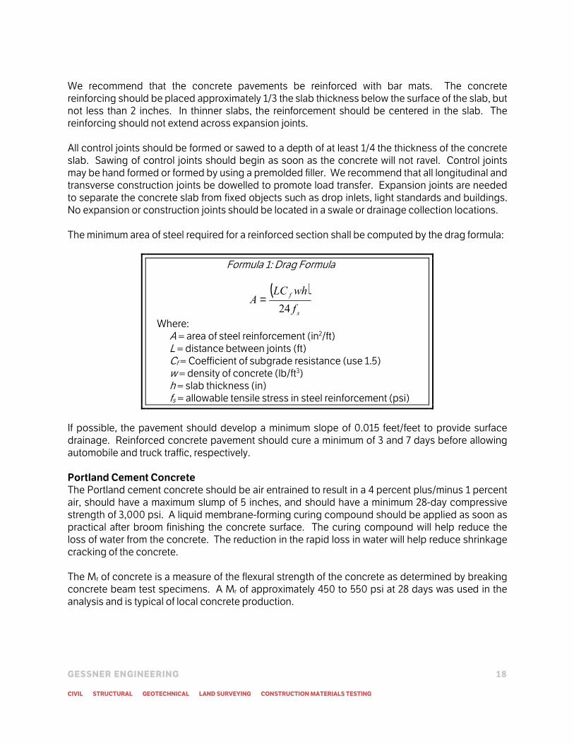
We recommend that the concrete pavements be reinforced with bar mats. The concrete reinforcing should be placed approximately 1/3 the slab thickness below the surface of the slab, but not less than 2 inches. In thinner slabs, the reinforcement should be centered in the slab. The reinforcing should not extend across expansion joints. All control joints should be formed or sawed to a depth of at least 1/4 the thickness of the concrete slab. Sawing of control joints should begin as soon as the concrete will not ravel. Control joints may be hand formed or formed by using a premolded filler. We recommend that all longitudinal and transverse construction joints be dowelled to promote load transfer. Expansion joints are needed to separate the concrete slab from fixed objects such as drop inlets, light standards and buildings. No expansion or construction joints should be located in a swale or drainage collection locations. The minimum area of steel required for a reinforced section shall be computed by the drag formula:
Formula 1: Drag Formula
( )
s
f
f
whLCA
24=
Where: A = area of steel reinforcement (in2/ft) L = distance between joints (ft) Cf = Coefficient of subgrade resistance (use 1.5) w = density of concrete (lb/ft3) h = slab thickness (in) fs = allowable tensile stress in steel reinforcement (psi)
If possible, the pavement should develop a minimum slope of 0.015 feet/feet to provide surface drainage. Reinforced concrete pavement should cure a minimum of 3 and 7 days before allowing automobile and truck traffic, respectively. Portland Cement Concrete
The Portland cement concrete should be air entrained to result in a 4 percent plus/minus 1 percent air, should have a maximum slump of 5 inches, and should have a minimum 28-day compressive strength of 3,000 psi. A liquid membrane-forming curing compound should be applied as soon as practical after broom finishing the concrete surface. The curing compound will help reduce the loss of water from the concrete. The reduction in the rapid loss in water will help reduce shrinkage cracking of the concrete. The Mr of concrete is a measure of the flexural strength of the concrete as determined by breaking concrete beam test specimens. A Mr of approximately 450 to 550 psi at 28 days was used in the analysis and is typical of local concrete production.

GESSNER ENGINEERING 19
CIVIL STRUCTURAL GEOTECHNICAL LAND SURVEYING CONSTRUCTION MATERIALS TESTING
Flexible Pavement
Flexible pavement sections recommended for this site are as listed in the table below:
Layer Material Passenger Vehicle Load Bus and Fire Lane
Material Thickness (inches) Material Thickness (inches)
Asphaltic Concrete 1.5 2.0
Crushed Limestone Base 8.0 8.0
Table 4: Flexible Pavement System Recommendations Garbage Dumpsters
Where flexible pavements are constructed at any site, we recommend that reinforced concrete pads be provided in front of and beneath trash receptacles. The dumpster trucks, if any, should be parked on the rigid pavement when the receptacles are lifted. It is suggested that such pads also be provided in drives where the dumpster trucks make turns with small radii to access the receptacles. The concrete pads at this site should be a minimum of 6 inches thick and reinforced with conventional steel reinforcing bars. Sidewalks
Concrete sidewalks are planned throughout the facility for pedestrian traffic. We recommend that subgrade stabilization shall be extended beneath sidewalks to reduce movement that would interfere with required ADA specifications. Reference the concrete and subgrade sections below for details. Flexible Base Course
The flexible base course should be crushed limestone conforming to TxDOT Standard Specifications, Item 247, Type A, Grades 1 or 2. Base course should be placed in lifts with a maximum thickness of 8 inches and compacted to a minimum of 95 percent of the maximum density at a moisture content within the range of 2 percentage points below to 2 percentage points above the optimum moisture content as determined by Tex-113-E.
Asphaltic Concrete Surface Course
The asphaltic concrete surface course should conform to TxDOT Standard Specifications, Item 340, Type D. The asphaltic concrete should be compacted to a minimum of 92 percent of the maximum theoretical specific gravity (Rice) of the mixture determined according to Test Method Tex-227-F. Pavement specimens, which shall be either cores or sections of asphaltic pavement, will be tested according to Test Method Tex-207-F. The nuclear-density gauge or other methods which correlate satisfactorily with results obtained from project roadway specimens may be used when approved by the Engineer. Unless otherwise shown on the plans, the Contractor shall be responsible for obtaining the required roadway specimens at their expense and in a manner and at locations selected by the Engineer. Pavement Earthwork If required, fill used beneath pavement shall have a plasticity index between 5 and 30. Any fill beneath pavement shall be compacted to a minimum of 95 percent of the maximum density as determined by the modified moisture/density relation (ASTM D 1557) at -2 to +2 percent of the
GESSNER ENGINEERING 20
CIVIL STRUCTURAL GEOTECHNICAL LAND SURVEYING CONSTRUCTION MATERIALS TESTING
optimum moisture content. (As an alternate, compaction to at least 98 percent of the ASTM D-698 maximum dry density may be considered). Pavement Drainage Considerations
As with any soil-supported structure, the satisfactory performance of a pavement system is contingent on the provision of adequate surface and subsurface drainage. Insufficient drainage which allows saturation of the pavement subgrade and/or the supporting granular pavement materials will reduce the performance and service life of the pavement systems. Surface and subsurface drainage considerations crucial to the performance of pavements at this site include (but are not limited to) the following:
1) Any known natural or man-made subsurface seepage at the site which may occur at sufficiently shallow depths as to influence moisture contents within the subgrade should be intercepted by drainage ditches or below grade French drains.
2) Final site grading should eliminate isolated depressions adjacent to curbs which may allow surface water to pond and infiltrate into the underlying soils. Curbs
should completely penetrate subgrade materials and should be installed to
sufficient depth to reduce infiltration of water beneath the curbs. 3) Pavement surfaces should be maintained to help minimize surface ponding and to
provide rapid sealing of any developing cracks. These measures will help reduce infiltration of surface water downward through the pavement section.
Other Issues Large trees adjacent to the foundation should be avoided, as they can affect soil moisture contents significantly by creating concentrations of dry soils around the trees. If trees adjacent to the foundation cannot be avoided, property owners should maintain the drip line of the trees, which is typically consistent with the root system, and can help keep the root system from causing
foundation issues. Maintenance of the entire landscape is a good practice for maintaining consistent moisture contents and minimizing foundation movement. Proper landscape maintenance uses vegetation as a natural moisture content indicator, as both over and under watering will result in distress of the plants. Any element that can affect the moisture content of the soils supporting the foundation, such as pools or plumbing, pose a risk to stiffened slab-on-grade foundations. Care should be taken to prevent and quickly repair any leaks to minimize damage to the foundation. Care should be taken when constructing adjacent to slopes to prevent bearing capacity failure due to nearby slope failure. For slopes steeper than 1 to 1, section 1808.7.2 of the 2012 International Building Code recommends a minimum set back from slopes of 15 feet or one-half the height of the slope.
Construction Materials Testing The performance of foundation systems and pavements are highly dependent upon the quality of construction. Compaction testing of fill material and concrete strength tests are required by the

GESSNER ENGINEERING 21
CIVIL STRUCTURAL GEOTECHNICAL LAND SURVEYING CONSTRUCTION MATERIALS TESTING
International Building Code. Therefore, we recommend that the foundation installation be monitored by Gessner Engineering to identify the proper founding strata and depths and to help evaluate building pad and foundation construction. We would be pleased to develop a plan for foundation monitoring to be incorporated in the overall quality control program. Please contact Gessner Engineering for more information.

GESSNER ENGINEERING 22
CIVIL STRUCTURAL GEOTECHNICAL LAND SURVEYING CONSTRUCTION MATERIALS TESTING
General Comments Shallow foundation excavations should be observed by the Geotechnical Engineer or their representative prior to placement of reinforcing steel and concrete. This is necessary to observe that the founding soils at the bottom of the excavations are similar to those encountered in our borings and that excessive loose materials and water are not present in the excavations. If soft pockets of soil are encountered in the foundation excavations, they should be removed and replaced with a compacted non-expansive fill material or lean concrete up to the design foundation bearing elevations. Gessner Engineering would be pleased to provide foundation design review, foundation inspection prior to the concrete pour, and construction materials testing. The analysis and recommendations presented in this report are based upon the data obtained from the borings performed at the indicated locations and from other information discussed in this report. This report does not reflect variations that may occur between bore holes, across the site, or due to the modifying effects of weather. The nature and extent of such variations may not become evident until during or after construction. If variations appear, Gessner Engineering should be immediately notified so that further evaluation and supplemental recommendations can be provided.
Limitations The scope of services for this project does not include, either specifically or by implication, any environmental or biological (e.g., mold, fungi, and bacteria) assessment of the site or identification or prevention of pollutants, hazardous materials, or conditions. If the owner is concerned about the potential for such contamination or pollution, other studies should be undertaken. For any excavation construction activities at this site, all Occupational Safety and Health Administration (OSHA) guidelines and directives should be followed by the Contractor during construction to ensure a safe working environment. In regards to worker safety, OSHA Safety and Health Standards require the protection of workers from excavation instability in trench situations.
This report has been prepared for the exclusive use of Mr. Steven Craney with Goree Architects, Inc., for the specific application to the project discussed and has been prepared in accordance with generally accepted geotechnical engineering practices. This report was written and recommendations were made based on the soil data collected on September 3, 2015. If construction is delayed or the proposed area experiences severe weather conditions, please contact the geotechnical engineer prior to construction. No warranties, either expressed or implied, are intended or made. In the event that changes in the nature, design, or location of the project as outlined in this report are planned, the conclusions and recommendations contained in this report shall not be considered valid unless Gessner Engineering reviews the changes and either verifies or modifies the conclusions of this report in writing.

GESSNER ENGINEERING 23
CIVIL STRUCTURAL GEOTECHNICAL LAND SURVEYING CONSTRUCTION MATERIALS TESTING
APPENDIX
� Summary
� Project Layout
� Boring Logs
� Symbols & Terms
� Geological Terms
Mobile B-37 Drill Rig: Bubba Red
GESSNER ENGINEERING 24
CIVIL STRUCTURAL GEOTECHNICAL LAND SURVEYING CONSTRUCTION MATERIALS TESTING
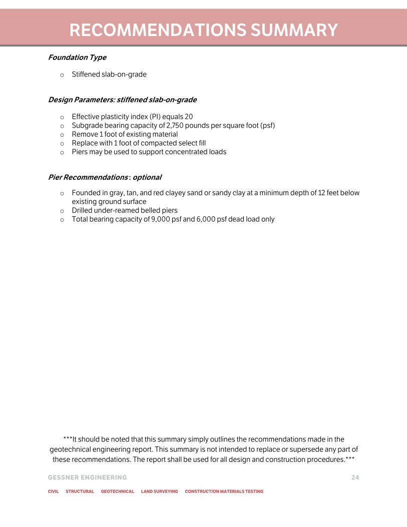
RECOMMENDATIONS SUMMARY
Foundation Type
o Stiffened slab-on-grade
Design Parameters: stiffened slab-on-grade
o Effective plasticity index (PI) equals 20
o Subgrade bearing capacity of 2,750 pounds per square foot (psf)
o Remove 1 foot of existing material
o Replace with 1 foot of compacted select fill
o Piers may be used to support concentrated loads
Pier Recommendations : optional
o Founded in gray, tan, and red clayey sand or sandy clay at a minimum depth of 12 feet below
existing ground surface
o Drilled under-reamed belled piers
o Total bearing capacity of 9,000 psf and 6,000 psf dead load only
***It should be noted that this summary simply outlines the recommendations made in the
geotechnical engineering report. This summary is not intended to replace or supersede any part of
these recommendations. The report shall be used for all design and construction procedures.***

www.gessnerengineering.com |979.680.8840
2501 Ashford Drive, Suite 102 | College Station, Texas 77840
College Station | Brenham | Fort Worth | San Antonio
TOMBALL, TEXAS
TOMBALL FORD REMODEL
Drawing No.
NTSScale
Job No. 15-0747
Drawn By
Checked By
Drawn Date
MJR
1
AMP
09.11.15
TBPE F-7451 TBPLS F-1093910
22702 TOMBALL PARKWAY
N
BH-2
BH-3
BH-1
T
O
M
B
A
L
L
P
A
R
K
W
A
Y
T
E
X
A
S
2
4
9
A
C
C
E
S
S
R
O
A
D
TERMINATED AT 20 FEET
DRY AT COMPLETION
DE
PT
H
(IN
F
EE
T)
WA
TE
R L
EV
EL
SA
MP
LE
T
YP
E
PE
NE
TR
OM
ET
ER
OR
B
LO
W C
OU
NT
CO
MP
RE
SS
IV
E
ST
RE
NG
TH
(ts
f)
% P
AS
SIN
G
#2
00
S
IE
VE
(%
)
CL
AS
SIF
IC
AT
IO
N
LIQ
UID
LIM
IT
(%
)
PL
AS
TIC
IT
Y
IN
DE
X
MO
IS
TU
RE
CO
NT
EN
T (%
)
DR
Y D
EN
SIT
Y
(p
cf)
LOG OF BORING NO: 1
DESCRIPTION OF STRATUM
CORING SAMPLE
SHELBY TUBE SAMPLE
STANDARD PENETRATION SAMPLE
AUGERING (DISTURBED) SAMPLE
NO RECOVERY
INITIAL WATER LEVEL
WATER LEVEL AFTER
5
10
22 11
1.0
4.0
10.5 50 CL
12.0 120.0
18 8 11.6 123.6 54 1.40 CL
13.2
29 16 11.7 77 CL
13.8 121.9 2.45
11.9
2.0
3.0
4.5
2.0
4.5
4.5+
3.0
3.5
15
20
25
30
with gravel
with silty sand seams
CLAY, Very Stiff to Hard, Gray, Tan, and Red, with sand
POSSIBLE FILL: CLAY, Sandy, Firm to Hard, Gray and
Brown
SO
IL
S
YM
BO
L
CLIENT: Goree Architects, Inc. APPROXIMATE LOCATION:
PROJECT: Tomball Ford Remodel N 30° 00' 54.3"
22702 Tomball Parkway W 95° 35' 24.3"
Tomball, Texas
GROUND SURFACE:
PROJECT NO: 15-0747 Existing Asphalt Parking
DATE: 09/03/2015
DRILLER: Gessner Engineering
0-3" ASPHALT
CLAY, Silty, Stiff to Hard, Gray
3"-12" BASE MATERIAL: CRUSHED LIMESTONE
TERMINATED AT 20 FEET
DRY AT COMPLETION
DE
PT
H
(IN
F
EE
T)
WA
TE
R L
EV
EL
SA
MP
LE
T
YP
E
PE
NE
TR
OM
ET
ER
OR
B
LO
W C
OU
NT
CO
MP
RE
SS
IV
E
ST
RE
NG
TH
(ts
f)
% P
AS
SIN
G
#2
00
S
IE
VE
(%
)
CL
AS
SIF
IC
AT
IO
N
LIQ
UID
LIM
IT
(%
)
PL
AS
TIC
IT
Y
IN
DE
X
MO
IS
TU
RE
CO
NT
EN
T (%
)
DR
Y D
EN
SIT
Y
(p
cf)
LOG OF BORING NO: 2
DESCRIPTION OF STRATUM
CORING SAMPLE
SHELBY TUBE SAMPLE
STANDARD PENETRATION SAMPLE
AUGERING (DISTURBED) SAMPLE
NO RECOVERY
INITIAL WATER LEVEL
WATER LEVEL AFTER
5
10
4.512.7
23 12 12.7 116.9 41 0.92 SC
9.8
14 7 11.6 55
12.0 125.6 4.32
25 14 12.4 44 SC
12.4
2.0
2.25
1.75
2.0
1.5
3.0
4.0
3.0
3.5
3.0
4.0
15
20
25
30
0-3" ASPHALT
SAND, Clayey, Very Dense, Gray, Red, Tan, and Brown
POSSIBLE FILL: SAND, Clayey, Dense to Very Dense,
Gray, Tan, and Red
SO
IL
S
YM
BO
L
CLIENT: Goree Architects, Inc. APPROXIMATE LOCATION:
PROJECT: Tomball Ford Remodel N 30° 00' 55.5"
22702 Tomball Parkway W 95° 35' 23.6"
Tomball, Texas
GROUND SURFACE:
PROJECT NO: 15-0747 Existing Asphalt Parking
DATE: 09/03/2015
DRILLER: Gessner Engineering
CLAY, Silty, Stiff to Very Stiff, Gray
TERMINATED AT 20 FEET
DRY AT COMPLETION
DE
PT
H
(IN
F
EE
T)
WA
TE
R L
EV
EL
SA
MP
LE
T
YP
E
PE
NE
TR
OM
ET
ER
OR
B
LO
W C
OU
NT
CO
MP
RE
SS
IV
E
ST
RE
NG
TH
(ts
f)
% P
AS
SIN
G
#2
00
S
IE
VE
(%
)
CL
AS
SIF
IC
AT
IO
N
LIQ
UID
LIM
IT
(%
)
PL
AS
TIC
IT
Y
IN
DE
X
MO
IS
TU
RE
CO
NT
EN
T (%
)
DR
Y D
EN
SIT
Y
(p
cf)
LOG OF BORING NO: 3
DESCRIPTION OF STRATUM
CORING SAMPLE
SHELBY TUBE SAMPLE
STANDARD PENETRATION SAMPLE
AUGERING (DISTURBED) SAMPLE
NO RECOVERY
INITIAL WATER LEVEL
WATER LEVEL AFTER
5
10
24 11 13.6 38 SC
18 8
11.7 121.6 1.13
13.2 51 CL
12.5
28 16 12.2 63 CL
11.6
11.6 122.6 2.91
2.0
2.0
2.0
3.0
3.0
4.5
4.5
4.0
4.5
15
20
25
30
0-3" ASPHALT
CLAY, Sandy, Very Stiff to Hard, Gray, Tan, and Red
FILL: CLAY, Sandy, Very Stiff, Gray and Brown, with silty
sand seams, roots, and metal debris
SO
IL
S
YM
BO
L
CLIENT: Goree Architects, Inc. APPROXIMATE LOCATION:
PROJECT: Tomball Ford Remodel N 30° 00' 53.3"
22702 Tomball Parkway W 95° 35' 23.0"
Tomball, Texas
GROUND SURFACE:
PROJECT NO: 15-0747 Existing Asphalt Parking
DATE: 09/03/2015
DRILLER: Gessner Engineering
3"-11" BASE MATERIAL: CRUSHED LIMESTONE
11"-20" FILL: SAND, Clayey, Brown and Gray

COARSE GRAINED SOILS (Major Portion Retained on No. 200 Sieve): Includes (1) clean gravels
and sands and (2) silty or clayey gravels and sands. Condition is rated according to relative
density, as determined by laboratory tests.
FINE GRAINED SOILS (Major Portion Passing No. 200 Sieve): Includes (1) inorganic and organic
silts and clays; (2) gravelly, sandy, or silty clays; and (3) clayey silts. Consistency is rated according
to shearing strength, as indicated by penetrometer readings or by unconfined compression tests.
Note: Slickensided and fissured clays may have lower unconfined compressive strengths than shown above due
to planes of weakness or cracks in the soil.
Parting - paper thin in size Seam - 1/8" to 3/8" thick Layer - greater than 3"
Slickensided
Fissured
Laminated
Interbedded
Calcareous
Well graded
Poorly graded
Flocculated
CLAY SILT SANDSTONE
SANDY
GRAVEL
LIMESTONE SHALE ASPHALTFILL CONCRETE
CLAYEYSAND
GRAVELLY
SILTY
SYMBOLS AND TERMS USED ON BORING LOGS
SOIL SYMBOLS AND DESCRIPTION SAMPLER TYPES
SAMPLE LOST
AUGER
SPLIT SPOON
SHELBY TUBE
TERMS DESCRIBING CONSISTENCY OR CONDITION
Standard Penetration,
N-Value, blows/ft
0-4
4-10
10-30
30-50
>50
Relative Density
Very Loose
Loose
Medium Dense
Dense
Very Dense
Pocket Penetrometer
Reading
0-0.25
0.25-0.5
0.5-1.0
1.0-2.0
2.0-4.0
>4.0
Consistency
Very Soft
Soft
Firm
Stiff
Very Stiff
Hard
Cohesive Strength, tons/sf
less than 0.125
0.125 to 0.25
0.25 to 0.50
0.50 to 1.00
1.00 to 2.00
2.00 and higher
Standard Penetration,
N-Value, blows/ft
0-2
2-4
4-8
8-15
15-30
>30
EXPANSION POTENTIAL OF COHESIVE SOILS
Plasticity Index
0-5
5-10
10-20
20-40
>40
Degree of Expansive Potential
Nonplastic
Low
Moderate
High
Very High
TERMS CHARACTERIZING SOIL STRUCTURE
- having inclined planes of weakness that are slick and glossy in appearance
- containing shrinkage cracks, frequently filled with fine sand or silt; usually more or less vertical
- composed of thin layers of varying color and texture
- composed of alternate layers of different soil types
- containing appreciable quantities of calcium carbonate
- having wide range in grain sizes and substantial amounts of all intermediate particle sizes
- predominantly of one grain size, or having a range of sizes with some intermediate size missing
- pertaining to cohesive silts that exhibit a loose knit or flakey structure
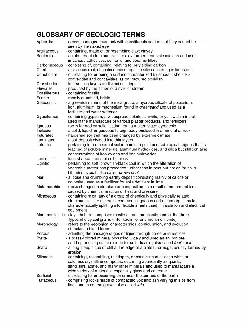
GLOSSARY OF GEOLOGIC TERMS Aphanitic - dense, homogeneous rock with constituents so fine that they cannot be seen by the naked eye Argillaceous - containing, made of, or resembling clay; clayey Bentonitic - an absorbent aluminum silicate clay formed from volcanic ash and used in various adhesives, cements, and ceramic fillers Carbonaceous - consisting of, containing, relating to, or yielding carbon Chert - a siliceous rock of chalcedonic or opaline silica occurring in limestone Conchoidal - of, relating to, or being a surface characterized by smooth, shell-like convexities and concavities, as on fractured obsidian Crossbedded - intersecting layers of distinct soil deposits Fluviatile - produced by the action of a river or stream Fossiliferous - containing fossils Friable - readily crumbled, brittle Glauconitic - a greenish mineral of the mica group, a hydrous silicate of potassium,
iron, aluminum, or magnesium found in greensand and used as a fertilizer and water softener
Gypsiferous - containing gypsum; a widespread colorless, white, or yellowish mineral, used in the manufacture of various plaster products, and fertilizers Igneous - rocks formed by solidification from a molten state; pyrogenic Inclusion - a solid, liquid, or gaseous foreign body enclosed in a mineral or rock. Indurated - hardened soil that has been changed by extreme climate Laminated - a soil deposit divided into thin layers Lateritic - pertaining to red residual soil in humid tropical and subtropical regions that is
leached of soluble minerals, aluminum hydroxides, and silica but still contains concentrations of iron oxides and iron hydroxides.
Lenticular - lens-shaped grains of soil or rock Lignitic - pertaining to soft, brownish-black coal in which the alteration of vegetable matter has proceeded further than in peat but not as far as in bituminous coal; also called brown coal Marl - a loose and crumbling earthy deposit consisting mainly of calcite or dolomite; used as a fertilizer for soils deficient in lime Metamorphic - rocks changed in structure or composition as a result of metamorphism
caused by chemical reaction or heat and pressure Micaceous - containing mica; any of a group of chemically and physically related aluminum silicate minerals, common in igneous and metamorphic rocks, characteristically splitting into flexible sheets used in insulation and electrical
equipment Montmorillonitic - clays that are comprised mostly of montmorillonite; one of the three types of clay soil grains (illite, kaolinite, and montmorillonite) Morphology - refers to the geological characteristics, configuration, and evolution
of rocks and land forms Porous - admitting the passage of gas or liquid through pores or interstices Pyrite - a brass-colored mineral occurring widely and used as an iron ore and in producing sulfur dioxide for sulfuric acid; also called fool's gold Scarp - a long steep slope or cliff at the edge of a plateau or ridge; usually formed by
erosion Siliceous - containing, resembling, relating to, or consisting of silica; a white or colorless crystalline compound occurring abundantly as quartz, sand, flint, agate, and many other minerals and used to manufacture a wide variety of materials, especially glass and concrete Surficial - of, relating to, or occurring on or near the surface of the earth Tuffaceous - comprising rocks made of compacted volcanic ash varying in size from fine sand to coarse gravel; also called tufa