Geotechnical Engineering Report - COB Home
166
Geotechnical Engineering Report Post Point Wastewater Treatment Plant Improvements Bellingham, Washington for Carollo Engineers October 6, 2010 600 Dupont Street Bellingham, Washington 98225 360.647.1510
Transcript of Geotechnical Engineering Report - COB Home
Geotechnical Engineering Report
Post Point Wastewater Treatment
Plant Improvements
Bellingham, Washington
for
Carollo Engineers
October 6, 2010
600 Dupont Street
Bellingham, Washington 98225
360.647.1510
October 6, 2010
Carollo Engineers
1218 Third Avenue, Suite 1600 Seattle, Washington 98101
Attention: Brian Matson, PE
Subject: Geotechnical Engineering Services Post Point Wastewater Treatment Plant Improvements Bellingham, Washington File No. 003562-106-00
GEOENGINEER~
600 Dupont Street Bellingham, Washington 98225
360.647.1510
We are pleased to submit 11 copies of our report, "Geotechnical Engineering Services, Post Point Wastewater Treatment Plant Improvements, Bellingham, Washington." Our geotechnical services were completed in general accordance with our proposal dated May 2, 2010. Our services were authorized by Brian Matson of Carollo Engineers on May 28, 2010.
We appreciate the opportunity to work with Carollo Engineers on this project. Please call if you
have any questions regarding this report.
Sincerely,
SWC:JRG:ims https;//projects.geoengineers.com/sites/00356-106-00/Finals/Report
GEOENGINEER~

Geotechnical Engineering Report
Post Point Wastewater Treatment Plant Improvements
Bellingham, Washington
Prepared for:
Carollo Engineers 1218 Th ird Avenue, Suite 1600 Seattle, Washington 98101
Attention: Brian Matson, PE
Prepared by:
GeoEngineers, Inc.
600 Dupont Street Bellingham, Washington 98225 360.647.1510
Sean W. Cool, PE
Project Geotechnica l Engineer
SWC:JRG:ims https://projects.geoengineers.com/sites/0035610600/
Fiie No. 0356-106-00
October 6, 2010
J. Robert Gordon, PE Principal
Disclaimer: Any electronic form, facsimile or hard copy of the original document (email, text, table, and/or figure) , if provided, and any attachments are only a copy of the original document. The original document is stored by GeoEngineers, Inc. and will serve as the official document of record.
GEoENGINEERs CJ

October 6, 2010 | Page i File No. 0356-106-00
Table of Contents
1.0 INTRODUCTION AND SCOPE OF SERVICES ....................................................................................... 1
2.0 PROJECT DESCRIPTION ...................................................................................................................... 1
3.0 SITE BACKGROUND AND RESEARCH ................................................................................................ 2
4.0 SITE CONDITIONS ................................................................................................................................. 3
4.1. Surface Conditions ........................................................................................................................ 3
4.2. Geologic Setting ............................................................................................................................ 3
4.3. Geologically Hazardous Areas ...................................................................................................... 4
4.3.1. Erosion Hazard Areas ........................................................................................................ 4
4.3.2. Landslide Hazard Areas .................................................................................................... 4
4.3.3. Seismic Hazard Areas ....................................................................................................... 5
4.3.4. Mine Hazard Areas ............................................................................................................ 5
4.4. Subsurface Conditions ................................................................................................................. 6
4.4.1. Subsurface Exploration ..................................................................................................... 6
4.4.2. Soil Conditions ................................................................................................................... 6
4.4.3. Groundwater Conditions ................................................................................................... 7
5.0 CONCLUSIONS AND RECOMMENDATIONS ....................................................................................... 8
5.1. Summary of Geotechnical Considerations .................................................................................. 8
5.1.1. Secondary Clarifier No. 4 (Facility No. 330) ..................................................................... 8
5.1.2. Activated Sludge Basin No. 4 (Facility 311) and Odor Control Facility (Facility 312) .... 9
5.1.3. Blower Building (Facility 325) ........................................................................................... 9
5.1.4. Selector/Activated Sludge Basin No. 1 (Facility 305) and Odor Control Facility
(Facility 306) .................................................................................................................... 10
5.1.5. Chemically Enhanced Primary Treatment Facility (Facility 240) .................................. 10
5.2. Geologic Hazards and Mitigation ............................................................................................... 11
5.2.1. Erosion Hazard Considerations ...................................................................................... 11
5.2.2. Seismic Hazard Considerations ...................................................................................... 11
5.2.3. Seismic Ground Motion Design Values .......................................................................... 12
5.2.4. Liquefaction and Lateral Spreading ............................................................................... 12
5.2.5. Surface Fault Rupture ..................................................................................................... 13
5.2.6. Tsunami Hazard Areas .................................................................................................... 13
5.3. Pile Foundation Recommendations ........................................................................................... 13
5.3.1. Augercast Piles ................................................................................................................ 14
5.3.2. Vertical Axial Capacities .................................................................................................. 14
5.3.3. Lateral Capacities ............................................................................................................ 15
5.3.4. Settlement ....................................................................................................................... 16
5.3.5. Construction Considerations .......................................................................................... 16
5.4. Shallow Foundation Recommendations .................................................................................... 18
5.4.1. General ............................................................................................................................. 18
5.4.2. Footing Design ................................................................................................................. 18
5.4.3. Mat Foundation Recommendations ............................................................................... 19
5.4.4. Overexcavation for Selector/Activated Sludge Basin No. 1 .......................................... 19
5.4.5. Lateral Resistance ........................................................................................................... 20

Page ii
5.4.6. Shallow Foundation Settlement ..................................................................................... 20
5.5. Slab-On-Grade Support ............................................................................................................... 20
5.6. Additional Design for Below Grade Structures .......................................................................... 21
5.6.1. Lateral Earth Pressures .................................................................................................. 21
5.6.2. Buoyancy and Uplift ......................................................................................................... 22
5.6.3. Drainage for Activated Sludge Basin No. 1 (Facility 305) ............................................. 22
5.6.4. Buried Slabs..................................................................................................................... 22
5.7. Pipe Design Considerations ....................................................................................................... 23
5.7.1. General ............................................................................................................................. 23
5.7.2. Pipeline Support .............................................................................................................. 23
5.7.3. Structural and Trench Backfill ........................................................................................ 24
5.7.4. Pipe Settlement ............................................................................................................... 24
5.8. Corrosion Potential ..................................................................................................................... 25
5.9. Earthwork .................................................................................................................................... 26
5.9.1. General ............................................................................................................................. 26
5.9.2. Site Preparation ............................................................................................................... 26
5.9.3. Base Preparation ............................................................................................................. 27
5.9.4. Temporary Excavations ................................................................................................... 27
5.9.5. Temporary Cut Slopes ..................................................................................................... 28
5.9.6. Temporary Shoring .......................................................................................................... 30
5.9.7. Wet Weather Earthwork and Erosion Control ................................................................ 31
5.10.Construction Dewatering ............................................................................................................ 32
5.10.1. General ............................................................................................................................. 32
5.10.2. Open Pumping ................................................................................................................. 32
5.10.3. Pumped Wells .................................................................................................................. 33
5.10.4. Wellpoints ........................................................................................................................ 33
5.10.5. Dewatering Qualifications and Experience .................................................................... 33
5.10.6. Dewatering Limitations ................................................................................................... 34
5.11.Pavement .................................................................................................................................... 34
6.0 CONSTRUCTION OBSERVATION SERVICES .................................................................................... 35
7.0 LIMITATIONS ...................................................................................................................................... 35
8.0 REFERENCES ..................................................................................................................................... 35
List Of Figures
Figure 1. Vicinity Map
Figure 2. Site and Exploration Plan
Figure 3. Subsurface Cross-Section A-A’
Figure 4. Subsurface Cross-Section B-B’
Figure 5. Subsurface Cross-Section C-C’
Figure 6. Subsurface Cross-Section D-D’
Figure 7. Subsurface Cross-Section E-E’
Figure 8. 5% Damped Site Specific MCE Response Spectra, 2475 YR EQ Event
Figures 9 to 12. Plots of LPILE Analysis Results
Figure 13. Schematic of Overexcavation at Selector/Activated Sludge Basin No. 1

October 6, 2010 | Page iii File No. 0356-106-00
Figures 14 and 15. Earth Pressure Diagrams for Tempoarary Shoring
APPENDICES
Appendix A. Field Explorations and Laboratory Testing
Figure A-1 – Key to Exploration Logs
Figures A-2 through A-15 – Logs of Borings
Figures A-16 through A-18 – Logs of Test Pits
Figures A-19 and A-20 – Log of CPT and Shear Wave Velocity Plot (In Situ Engieering)
Appendix B. Laboratory Testing
Figures B-1 through B-14 – Sieve Analysis Results
Figures B-15 through B-18 – Atterberg Limits Test Results
Figures B-19 through B-24 – Corrosion Potential Test Results (ALS Group)
Appendix C. Previous Site Explorations
Appendix D. Site Specific Seismic Response Analysis
Figure D-1 – 5% Damped Response Spectra of Scaled Input Ground Motions
Figure D-2 – Design Shear Wave Velocity Profile
Figure D-3 – 5% Damped MCE Response Spectra at Surface
Figure D-4 – 5% Damped MCE Amplification Factor at Surface
Figure D-5 – 5% Damped Site Specific MCE Response Spectra
Appendix E. Report Limitations and Guidelines for Use
October 6, 2010 | Page 1 Field No. 00356-106-00
1.0 INTRODUCTION AND SCOPE OF SERVICES
This report presents the results of our design level geotechnical engineering services for the
proposed Wastewater Treatment Plant (WWTP) expansion at the existing City of Bellingham facility
at Post Point in Bellingham, Washington. The generalized location of the WWTP site is shown in the
Vicinity Map, Figure 1.
The purpose of our services was to explore subsurface soil and groundwater conditions at the
locations of the new facilities to provide geotechnical engineering recommendations for design.
Our scope of services included:
■ Research and review of available geotechnical information;
■ Completing geotechnical explorations including fourteen geotechnical borings, three test pits,
and one cone penetrometer test (CPT) with seismic shear wave velocity measurements;
■ Completing laboratory testing on samples obtained from the borings and test pits;
■ Performing engineering analyses and providing geotechnical conclusions and
recommendations for design and construction of the proposed expansion elements;
■ Preparing this geotechnical engineering report.
Our specific scope of services is described in Task Order No. 2, Agreement between Carollo
Engineers and GeoEngineers, City of Bellingham Contract Number 2008-0669 dated May 3, 2010
(which supersedes Task Order No. 1 dated March 2, 2009), and Task Order No. 3 for Additional
Site Investigations.
2.0 PROJECT DESCRIPTION
We understand that the original design for the WWTP was completed in 1971 with an expansion
that occurred in 1989. Our understanding of this proposed expansion project is based on
information provided by Carollo Engineers, including communications with Brian Matson and
Susanna Leung. Figure 2, attached, shows the existing WWTP including the 1989 expansion, with
proposed locations of the structures identified for these improvements.
As currently envisioned, the WWTP expansion will include five primary components as described
below:
■ Secondary Clarifier No. 4 (Facility No. 330) – The Secondary Clarifier No. 4 will be located in
the western portion of the site, south and west of existing clarifiers. The structure will be
approximately 120 feet in diameter with an inside base elevation ranging from about Elevation
7.6 feet at the perimeter to about Elevation +0 feet at the center. Foundation loads are
anticipated to be 1,500 pounds per square foot (psf) across the base of the foundation with a
concentrated 3,000 psf load at the perimeter wall.
■ Activated Sludge Basin No. 4 (Facility 311) and Odor Control (Facility 312) – The Activated
Sludge Basin No. 4 will be located in the southern portion of the site, immediately south of the
existing Oxygen Activated Sludge Basin. The sludge basin will be approximately 150 feet long

Page 2 | October 6, 2010 | GeoEngineers, Inc. File No. 00356-106-00
and 50 feet wide. The activated sludge basin will have an inside base elevation at about
Elevation 12.1 feet with an anticipated foundation load of 1,840 psf. Odor control for the new
sludge basin will be provided by an aerobic biofilter (if needed) with equipment supported on
an approximately 35 foot by 60 foot slab on grade structure at the existing ground surface
(near Elevation 20 feet).
■ Blower Building (Facility 325) – The Blower Building will be an approximately 60-foot by 80-foot
slab on grade structure with concrete tilt-up walls and metal roof deck and open-web steel
joists. Top of slab elevation for the structure will be similar to the adjacent driveway, at about
Elevation 22 feet, which will require cuts on the eastern portion of the structure up to about
5 feet. Total perimeter wall loads will be on the order of 4,000 pounds per lineal foot. The
building will house five blowers, a generator, and other miscellaneous equipment.
■ Selector/Activated Sludge Basin No. 1 (Facility 305) and Odor Control (Facility 306) – The
Selector/Activated Sludge Basin No. 1 will be located in the southeastern portion of the site,
south of the existing Headworks Building (Facility 120) Screenings Facility (Facility 110) and
east of the existing Oxygen Activated Sludge Basins (Facility 310). This basin will be
approximately 105 feet by 155 feet in plan dimension with an inside base elevation at about
Elevation 14 feet. Anticipated foundation loads for this structure are on the order of 1,920 psf.
Odor control for the new sludge basin will be provided by an aerobic biofilter with equipment
supported on an approximately 35-foot by 60-foot slab-on-grade structure at the existing
ground surface, near Elevation 22 feet.
■ Chemically Enhanced Primary Treatment Facility (Facility 240) – The Chemically Enhanced
Primary Treatment Facility (CEPT building) will be located in the northeast portion of the site,
near the existing headworks. This facility will be an approximately 30 feet by 82 feet slab on
grade structure with concrete tilt-up walls and metal roof deck and open-web steel joists. The
structure will house fluid tanks supported at/near existing site grades, typically on 1-foot thick
concrete pads in a slab-on-grade structure with perimeter footing. Total perimeter wall loads
will be on the order of 4,000 pounds per lineal foot.
3.0 SITE BACKGROUND AND RESEARCH
The site of the existing Post Point WWTP is an area of historic ground modification, including
excavation of peat and organic soils and backfill with structural fill and some excavation of granular
borrow soils in select areas of the site. The approximate extent of previous peat removal (based on
our review of the documents below) is shown in Figure 2. In addition to local geologic maps, we
have reviewed available subsurface information from the previous phases of site development,
including the following sources:
■ CH2M Hill, “Post Point Wastewater Treatment Plant Upgrade Geotechnical Design Report,”
September 1971.
■ CH2M Hill, “Post Point Wastewater Treatment Plant Upgrade Geotechnical Data Report,”
September 1989.
■ CH2M Hill, “Post Point Wastewater Treatment Plant Upgrade, Initial Design Review Submittal –
Design Guidelines,” September 1989.

October 6, 2010 | Page 3 Field No. 00356-106-00
4.0 SITE CONDITIONS
4.1. Surface Conditions
The project site is located in Fairhaven area of south Bellingham, southwest of the intersection of
McKenzie Avenue and 4th Street. The site is bounded by Bellingham Bay, an intertidal lagoon and
Burlington Northern Santa Fe railroad tracks and embankment to the west and northwest. An
industrial/transportation district is located to the north and northeast. A residential neighborhood
is located to the southeast, south and southwest, primarily on the raised bluffs above the site.
The site grades slope gently downward to the northwest towards Bellingham Bay with open grassy
areas present in the southwest and southeast corners of the site. Steeper slopes are present on
the margins of the site toward the south and east with heavier wooded vegetation on the bluff to
the southwest.
4.2. Geologic Setting
We reviewed various geologic maps for the project area (Easterbrook 1976, Lapen 2000, and
Department of Ecology 1977). The maps indicate that the site is underlain by the Chuckanut
Formation bedrock, Frasier drift, alluvium and artificial fill.
The Chuckanut Formation consists of sandstone, conglomerate, shale, and coal deposits. The
bedrock typically encountered in the study area consists of sandstone or siltstone. Bedrock was
mapped at/near the ground surface in both the Easterbrook and Lapen maps, although no surface
exposures of bedrock are present in the immediate project vicinity, and bedrock was not
encountered in the site explorations.
The Department of Ecology (Costal Zone Atlas) maps soils in the project vicinity as Frasier drift, an
undifferentiated glacial deposit composed of various glacial sources including glacial outwash,
terrace deposits, glaciomarine drift, and glacial till. The soil types in this unit will depend on the
depositional environment.
One predominant soil unit within the Frasier drift is a glaciomarine deposit locally referred to as
Bellingham (glaciomarine) Drift. This glaciomarine deposit consists of unsorted, unstratified silt
and clay with varying amounts of sand, gravel, cobbles and occasional boulders. Some discrete
but likely discontinuous sand layers were also encountered. Glaciomarine drift is derived from
sediment melted out of floating glacial ice that was deposited on the sea floor. Glaciomarine drift
was deposited during the Everson Interstade approximately 11,000 to 12,000 years ago while the
land surface was depressed 500 to 600 feet from previous glaciations. This unit is predominantly
medium stiff to soft and possesses relatively low shear strength and moderate to high
compressibility characteristics in a lowland environment. Glacial till, a subset of the Frasier drift, is
typically dense as a result of being overridden by glaciers, with resultant high hear strength and low
compressibility characteristics.
Alluvium typically consists of sand, gravel and silt with areas of clayey and organic soil, deposited
on beaches, spits, and modern flood plains, and may include some nearshore inter-tidal deposits.
Page 4 | October 6, 2010 | GeoEngineers, Inc. File No. 00356-106-00
The artificial fill identified at the site is the result of historical ground modification. The WWTP has
been located at the site since 1971. It appears that historically excavation likely occurred into the
hillside along the east side of the site. The lower portion of the site is located in an alluvial
environment with significant peat deposits. During previous site development, some of the peat
has been removed and fill has been brought into the site to raise grades to present elevations.
4.3. Geologically Hazardous Areas
Geologically hazardous areas are designated by the City of Bellingham Critical Areas Ordinance
(CAO) per Bellingham Municipal Code 16.55.410 – 16.55.460. In addition to the definition of the
geologically hazardous areas in the CAO, the City has developed a folio of maps that identify these
areas in their database. In general, the CAO requires that a qualified professional assess the
geologic hazards based on review of available information and field studies, evaluate the specific
project proposal with respect to relationship and impact on the hazard area and adjacent sites if
appropriate, provide minimum buffers and setbacks and provide mitigation strategies where
appropriate for specific geologic hazards. The geologically hazardous areas include erosion,
landslide, seismic and mines.
4.3.1. Erosion Hazard Areas
Erosion hazard areas are defined by the CAO as areas prone to soil erosion including:
■ Areas identified in soil unit maps of the U.S. Department of Agriculture Soil Conservation
Services Soil Survey of Whatcom County rated as “severe” due to “slope, wetness, ponding,
flooding, cutbanks cave” or any combination thereof.
■ Upland areas immediately adjacent to Bellingham Bay.
■ Any area where soil type is predominantly sand, clay, silt and/or organic matter and slopes
greater than 30 percent.
The soils mapping by the Soil Conservation Service Soil Survey of Whatcom County (SCS) does not
indicate if an erosion hazard is present at the project location; the site is mapped as urban land
and does not indicate the soil type. The site is not identified as an erosion hazard in the Geologic
Hazard Areas Map Folio. However, the site is adjacent to Bellingham Bay and does have soil types
that would be defined as an erosion hazard area by the CAO. Additionally, an erosion hazard would
exist where soils are disturbed during the earthwork phase of construction. Erosion hazard
mitigation is presented in a subsequent section of this report.
4.3.2. Landslide Hazard Areas
Landslide hazard areas are defined by the CAO as those susceptible to landslides and/or
subsidence that could include movement of soil, fill materials, rock or other geologic strata.
Specific landslide designations as defined by the CAO include:
■ Areas identified in soil unit maps of the U.S. Department of Agriculture Soil Conservation
Services Soil Survey of Whatcom County rated as “severe” due to “slope” and/or “subsides”.
■ Slopes equal to or greater than 40 percent grade (2.5H:1V [Horizontal:Vertical] or 22 degrees)
with an elevation change of at least 10 feet.

October 6, 2010 | Page 5 Field No. 00356-106-00
■ Slopes that are parallel or subparallel to planes of weakness in subsurface materials.
■ Current and historic marine bluffs along present and historical shorelines including Bellingham
Bay.
■ Areas depicted as landslide hazards by the Geologic Hazard Areas Map Folio, Bellingham,
Washington, 1991.
The soils mapping by the Soil Conservation Service Soil Survey of Whatcom County does not
indicate that a landslide hazard is present at the project location. The site does not currently have
slopes greater than 40 percent grade with at least 10 feet of vertical relief. The site is not
identified as a landslide hazard in the Geologic Hazard Areas Map Folio. Accordingly, the area does
not meet the definition of a landslide hazard area and landslide hazards will not be addressed
further in this report.
4.3.3. Seismic Hazard Areas
Seismic hazard areas are defined by the CAO as those areas subject to severe risk of damage as a
result of earthquake induced ground shaking, slope failure, settlement, soil liquefaction, lateral
spreading, or surface rupture. Specific areas of very high response to seismic shaking include:
■ All landfills placed waterward of the historic 1850 natural coastline of Bellingham Bay.
■ All alluvial deposits near the mouth (delta) of Whatcom Creek.
■ All marine and stream course bluffs greater than 10 feet in vertical relief and steeper than
100%.
■ All rock outcrops greater than 10 feet in vertical relief.
The site is identified in the Geologic Hazard Areas Map Folio as exhibiting a low response to
seismic shaking, however, some of the soils encountered in our explorations exhibit a moderate to
high potential response to seismic shaking. Although the site does not appear to meet the criteria
for definition as a seismic hazard area according to the CAO, it is located near the shoreline in an
area of modified land overlying a soft soil profile, and therefore is in a similar environment as a
recognized seismic hazard area. Accordingly, potential impacts and mitigation strategies have been
identified and are discussed in the subsequent sections of this report.
4.3.4. Mine Hazard Areas
Mine hazard areas are defined by the CAO as those areas underlain by or affected by historical
mine workings. Specific hazard areas include:
■ Areas depicted within the as Coal Mine Hazard Areas within the Geologic Hazard Areas
Map Folio, Bellingham, Washington, 1991.
The project site is located approximately 1,600 feet west of the Union Mine portal location based
on the Map Folio. No known mine workings are mapped at the project site. Accordingly, the area
does meet the definition of a mine hazard area and mine hazards will not be addressed further in
this report.

Page 6 | October 6, 2010 | GeoEngineers, Inc. File No. 00356-106-00
4.4. Subsurface Conditions
4.4.1. Subsurface Exploration
The subsurface exploration completed by GeoEngineers for this project consisted of fourteen
borings, three test pits, and a seismic cone penetration test (CPT). Borings GEI-1 through GEI-14
were completed on April 27, April 28, and July 15, 2010 using a hollow stem auger and were
advanced to depths ranging from 21.5 to 36.5 feet below existing ground surface (bgs).
GeoEngineers conducted three test pits at the site on May 4, 2010 to depths ranging from 8 to 9
feet bgs using a small tracked excavator. The CPT was advanced to a depth of 81.2 feet bgs on
April 26, 2010 with a track-mounted rig. All explorations were subcontracted to GeoEngineers.
The approximate locations of the explorations are shown in Figure 2, as well as the explorations
from previous studies completed at the site. Details of the field exploration program and the
exploration logs are presented in Appendix A. Details of the laboratory testing program completed
for this evaluation are presented in Appendix B. Relevant logs from previous site explorations in
the vicinity of the proposed WWTP expansion are provided in Appendix C.
4.4.2. Soil Conditions
Subsurface soils were classified as fill, alluvium/peat, undifferentiated glacial drift, and glacial till.
A description of each geologic unit is presented below. Representative subsurface cross-sections
are presented in Figures 3 through 7.
FILL. Fill of variable soil types and density/consistency was encountered in all our explorations,
except GEI-7, GEI-8, and TP-2, which were completed outside of the existing WWTP facility. The fill
was typically medium dense/stiff in the upper portion of the fill, grading to decreased
density/consistency with depth. The fill thickness ranged from 2 to 19.5 feet below ground surface
(bgs). Fill consisted of sand with gravel, sandy silt, silty/clayey sand, and sand with silt/clay. Some
scattered organic material was also encountered in the fill soils.
PEAT. A layer of soft to medium stiff peat over organic silt was encountered in GEI-1 from 9.5 to
15.5 feet bgs. We understand that extensive areas of peat were removed and replaced with
structural and non-structural fill during previous site development. The approximate extents of
previous peat removal at the site based on our research are shown in Figure 2. Peat was also
identified in previous explorations by others where we assume overexcavation was not performed
including boring B-9, B-10, and B-13.
ALLUVIUM. Soil interpreted to be alluvium was encountered in the southern and southwest portions
of the site in areas outside of the developed WWTP facility. Alluvium was encountered underlying
fill and/or sod in borings GEI-6, GEI-7, GEI-8, GEI-9, GEI-10, and GEI-14, and test pits TP-2, and TP-
3. The alluvial deposits encountered generally consisted of loose to medium dense and soft to
medium stiff sand with silt, silty sand and sandy silt with lesser amount of clayey soil. The alluvium
extended to depths ranging from 7 to 14 feet bgs. Test pits TP-2 and TP-3 terminated in this unit.
UNDIFFERENTIATED GLACIAL DRIFT. Undifferentiated glacial drift, primarily interpreted to be a
glaciomarine deposit, was encountered in all our boring locations except GEI-11. The glacial drift
encountered generally consists of soft to medium stiff silty and sandy clay with some clayey silt and
sand with variable gravel content. In the eastern portion of the site, near the proposed Blower

October 6, 2010 | Page 7 Field No. 00356-106-00
Building and CEPT Building, the glacial drift was medium stiff to stiff with some medium dense silty
sand. The glacial drift encountered in our explorations has a higher sand content than is typical for
glaciomarine deposits in upland areas. Based on the CPT data and our review of previous deeper
explorations, this unit has some interbedding/layering with more granular soils. All GEI borings
terminated in this unit except GEI-10 through GEI-14, which terminated in glacial till.
GLACIAL TILL. Glacial till, distinguished from the remainder of the undifferentiated glacial drift soil
units because of its higher density and lower moisture content, was encountered in borings GEI-10
through GEI-14 at depths of 3 to 24 feet bgs and during previous site exploration at variable
depths, up to 123 feet bgs. The glacial till encountered is typically dense to very dense silty sand
with gravel, with very stiff to hard sandy silt and clay at some locations.
4.4.3. Groundwater Conditions
Relatively shallow groundwater conditions were observed at the project site, consistent with the
nearshore location of the WWTP facility. Three piezometers were installed for this project at GEI-1,
GEI-2, and GEI-5 boring locations. Groundwater was generally encountered between Elevation 13
and 15 feet in the southern portion of the site and slightly lower, between about Elevation 10 and
12 feet in the western portion of the site. Similar groundwater elevations were measured during
exploration and monitoring for previous expansion, with groundwater ranging from Elevation 11.5
to 13 feet near B-9 and B-10 to Elevation 8 to 9 feet near Boring B-13 and B-14 (elevations
adjusted from City of Bellingham datum to NAVD). Groundwater levels should be expected to
fluctuate in response to rainfall, seasonal variations, possibly tidal variations, and other factors.
TABLE 1. GROUNDWATER CONDITIONS
Exploration
No.
Approximate
Surface
Elevation (ft)
Depth to
Groundwater
Seepage at Time
of Drilling (ft)
Groundwater
Seepage
Elevation at Time
of Drilling (ft)
Measured Depth
to Groundwater in
Piezometer (ft)(1)
Groundwater
Elevation in
Piezometer
(ft)(1)
GEI-1 13 17 -4 2.7 10.3
GEI-2 17 6 11 4.5 12.5
GEI-3 18 NE NE -- --
GEI-4 17.5 20.5 3 -- --
GEI-5 20 12 8 4.9 15.1
GEI-6 21 6 15 -- --
GEI-7 23 9 14 -- --
GEI-8 21 5.5 15.5 -- --
GEI-9 18.5 5.5 13 -- --
GEI-10 22 NE NE -- --
GEI-11 27 NE NE -- --
GEI-12 34 NE(2) NE(2) -- --
GEI-13 24 20 4 -- --
GEI-14 21 5 16 -- --

Page 8 | October 6, 2010 | GeoEngineers, Inc. File No. 00356-106-00
Exploration
No.
Approximate
Surface
Elevation (ft)
Depth to
Groundwater
Seepage at Time
of Drilling (ft)
Groundwater
Seepage
Elevation at Time
of Drilling (ft)
Measured Depth
to Groundwater in
Piezometer (ft)(1)
Groundwater
Elevation in
Piezometer
(ft)(1)
TP-1 15 8 7 -- --
TP-2 20 6.5 13.5 -- --
TP-3 23 NE NE -- --
NE – Not encountered
(1) – Measured June 11, 2010
(2) –Perched groundwater seepage was observed at a depth of 1 foot within the fill over the glaciomarine drift and is not
representative of the local water table at this location.
5.0 CONCLUSIONS AND RECOMMENDATIONS
5.1. Summary of Geotechnical Considerations
Based on our evaluation, construction of the WWTP expansion is feasible as proposed. The site
conditions include fill, peat, and naturally occurring compressible soils which must be carefully
considered to achieve desirable foundation performance of the various project components.
Additionally, a relatively shallow groundwater table is present that affects both design and
construction of below grade structures. This report section includes a preliminary summary of
geotechnical considerations for the proposed WWTP expansion. The recommendations in this
report section should only be used in conjunction with the full text of this report.
5.1.1. Secondary Clarifier No. 4 (Facility No. 330)
The proposed Secondary Clarifier No. 4 is located in area overlying compressible peat and a
significant differential thickness of soft to medium stiff clay (Figure 3). The adjacent clarifier
settled several inches differentially across the width of the structure and required post construction
mitigation to maintain system performance. The foundation loads are not fully compensated by the
excavation and similar settlement and performance would occur if the new structure was
supported on a shallow mat foundation. Accordingly, a pile supported mat foundation has been
selected by the design team as the preferred foundation alternative for the Secondary
Clarifier No. 4. Pile supporting this structure will limit total and differential settlement within the
desired respective 1½ inch total and ¾ inch differential tolerances.
■ Piles will consist of 18- or 24-inch augercast piles primarily deriving support from side friction
in the glacial drift; some piles may reach dense glacial till. Recommendations for augercast
pile axial and lateral capacity are presented in Section 5.3 of this report.
■ Excavation to the foundation subgrade will likely extend through existing fill and reach loose
alluvium, peat, and/or soft clay in places. Some additional subgrade stabilization may be
required to support equipment for pile installation as described in Section 5.9.3 of this report.
■ The depth of excavation for this structure will likely require temporary shoring and dewatering.
We recommend temporary shoring consisting of sheetpiles that also provide groundwater
cutoff and will limit construction dewatering. Recommendations for earth pressures for

October 6, 2010 | Page 9 Field No. 00356-106-00
temporary shoring are presented in Section 5.9.6 of this report. Recommendations for
dewatering are discussed in Section 5.10.
5.1.2. Activated Sludge Basin No. 4 (Facility 311) and Odor Control Facility (Facility 312)
These facilities are also located in an area underlain by loose alluvium and soft to medium stiff clay
(Figures 4 and 5). Peat was encountered in a nearby boring completed by others and could be
encountered, although it appears unlikely based on our exploration program. The loads for the
basin are higher than the weight of soil removed and are not fully compensated. Differential
settlement and seismic response would be problematic if constructed with shallow foundations.
Accordingly, a pile supported mat foundation has also been selected as the preferred foundation
support for this structure. The lighter, at-grade odor control facility may be constructed with
shallow foundations.
■ Piles will consist of 18- or 24-inch augercast piles primarily deriving support from end bearing
in the underlying dense glacial till. Recommendations for augercast pile axial and lateral
capacity are presented in Section 5.3 of this report.
■ Excavation to the foundation subgrade will likely extend through existing fill and reach loose
alluvium and/or soft clay in places. Some additional subgrade stabilization may be required to
support equipment for pile installation as described in Section 5.9.3 of this report.
■ The depth of excavation for this structure and adjacent infrastructure will likely require
temporary shoring. We recommend temporary shoring consisting of sheetpiles that also
provide groundwater cutoff and will limit construction dewatering. Recommendations for earth
pressures for temporary shoring are presented in Section 5.9.6 of this report.
Recommendations for dewatering are discussed in Section 5.10.
■ The odor control facility is a light facility. We recommend that the structure be supported by a
structural slab on grade with thickened edges for footings. Shallow foundation
recommendations are presented in Section 5.4.
5.1.3. Blower Building (Facility 325)
The proposed Blower Building will be constructed as a slight cut up to about 5 feet below existing
site grades in an area with a shallow thickness of fill overlying alluvium (Figure 6). The
groundwater table is not expected within the depth of excavation. The walls of the structure are
anticipated to be concrete tilt-up or concrete masonry unit (CMU). Because of variability in
underlying soils, site history of excavation and fill, and presence of a limited thickness of liquefiable
soils, some differential settlement could occur with traditional shallow foundations. We
recommend a mat foundation or tying internal foundations together with grade beams to help limit
differential settlement.
■ We recommend a mat foundation or slab-on grade with continuous perimeter grade-beam style
foundation with top and bottom steel reinforcement. We recommend any internal footings also
be tied together with grade beams, or possibly by placing some steel in the slab-on-grade and
connecting the slabs to the footings. The footings can be designed for an allowable bearing
pressure of 2,000 psf if supported on 12 inches of compacted structural fill. Mat foundations
may be designed with a subgrade modulus of about 30 pounds per cubic inch (pci). Shallow
foundation recommendations are presented in Section 5.4.

Page 10 | October 6, 2010 | GeoEngineers, Inc. File No. 00356-106-00
5.1.4. Selector/Activated Sludge Basin No. 1 (Facility 305) and Odor Control Facility (Facility 306)
The Selector/Activated Sludge Basin No. 1 is in an area of sloping ground and will be excavated
between 10 and 20 feet below existing site grades to reach the slab elevation of +14 feet
(Figure 7). If constructed as a mat foundation at Elevation 14 feet, the western portion of the mat
foundation would bear directly on dense glacial till while the eastern portion would be supported
medium stiff to stiff clayey glacial drift. The portion of the structure founded on glacial till will not
experience any appreciable settlement, with an increasing settlement magnitude toward the west;
therefore, any settlement that does occur will be differential across the basin. For planning
purposes, we recommend that the glacial drift in the western portion of the building footprint be
overexcavated down to dense glacial till and backfilled with densely compacted structural fill.
Alternatively, it may be more cost effective to use a series of slots or piers backfilled with controlled
density fill (CDF) or rammed aggregate piers (RAPs) that penetrate through the drift and bear on/in
the glacial till. We have provided recommendations for the overexcavation at this time, and
suggest re-evaluating alternatives once the project design is further along.
■ Based on explorations near the western building corners, overexcavation and replacement to
about Elevation +0 to -2 could be required to reach the dense glacial till.
■ Relatively steep temporary construction slopes will be feasible in the dense glacial till, and
likely in the glacial drift. Flatter slopes or shoring will be required for the cut in alluvium.
Recommendations for temporary slopes are provided in Section 5.9.5.
■ Excavation of the glacial till in the eastern portion of the basin will encounter very dense soil
that may be very difficult to excavate and require larger equipment or “ripping” to reach the
proposed subgrade elevation.
■ Even with overexcavation and replacement with structural fill, some potential for differential
settlement will remain. We recommend that the transition between cut into dense glacial till
and fill be spaced in steps over approximately 30 feet as described in Section 5.4.4.
■ If the RAP option is pursued further, noise generated during installation could be a factor for
protection of adjacent wildlife habitat. Excavated slots or piers backfilled with CDF would have
construction noise similar to other planned site activities.
■ The mat foundation on dense glacial till or structural fill placed and compacted directly over
glacial till, may be designed with a subgrade modulus of about 200 pci. A discussion of mat
foundations is presented in Section 5.4.3.
■ The odor control facility is a light facility. We recommend that the structure be supported by a
structural slab on grade with thickened edges for footings. Shallow foundation
recommendations are presented in Section 5.4.
5.1.5. Chemically Enhanced Primary Treatment Facility (Facility 240)
The proposed CEPT Facility will be constructed near existing site grades in an area with a shallow
thickness of fill overlying alluvium (Figure 6). The walls of the structure are anticipated to be
concrete tilt-up or concrete masonry unit (CMU). Because of variability in underlying soils, site
history of excavation and fill, and presence of a limited thickness of liquefiable soils, some
differential settlement could occur and we have recommend a mat foundation or structural slab
with perimeter grade beam type design to help limit differential settlement.

October 6, 2010 | Page 11 Field No. 00356-106-00
■ We recommend a mat foundation or structural slab-on grade with continuous perimeter grade-
beam style foundation with top and bottom steel reinforcement for support of the walls. The
perimeter footing can be designed for an allowable bearing pressure of 2,000 psf if supported
on 12 inches of compacted structural fill. Mat foundations may be designed with a subgrade
modulus of about 30 pci. Details of shallow foundation support are presented in Section 5.4.
5.2. Geologic Hazards and Mitigation
5.2.1. Erosion Hazard Considerations
The area of the proposed construction includes relatively flat or gently sloping areas of historical fill
or native alluvium and glacial drift. As currently envisioned, earthwork construction for the WWTP
expansion will require significant excavation to the proposed foundation elevations and
construction of the new structures. The primary erosion hazard at the site is from temporary
conditions created during construction. Temporary erosion control measures and Best
Management Practices (BMPs) are required during construction under current regulations to
mitigate on-site and off-site erosion potential, which is standard of practice.
In our opinion, provided typical erosion and sedimentation controls are implemented during
construction, the site does not present a significant erosion hazard. Stormwater should be
prevented from flowing across disturbed areas and not directed toward the slopes during
construction. Temporary erosion control measures should be used during construction depending
on the weather, location, soil/rock type, and other factors. Temporary erosion protection (e.g.,
straw, plastic, or rolled erosion control products [RECPs]) may be necessary to reduce sediment
transport until vegetation is established or permanent surfacing applied. Appropriate best
management practices (BMPs) should be incorporated into the temporary erosion and sediment
control plan by the civil engineer. All finished slopes should be protected and/or vegetated before
the rainy season. Provided that proper grading practices are used and BMPs incorporated into the
grading plans, we conclude that the erosion hazard will be adequately mitigated during site
development. During construction, the contractor would be subject to Ecology regulations which
require performance based testing of turbidity at all discharge points. Proper construction
practices and monitoring procedures will manage the risks to the standard of practice.
5.2.2. Seismic Hazard Considerations
5.2.2.1. SITE SEISMICITY
The site is located within the Puget Sound region, which is seismically active. Seismicity in this
region is attributed primarily to the interaction between the Pacific, Juan de Fuca and North
American plates. The Juan de Fuca plate is subducting beneath the North American plate. It is
thought that the resulting deformation and breakup of the Juan de Fuca plate might account for
the deep focus earthquakes in the region. Hundreds of earthquakes have been recorded in the
Puget Sound area. In recent history, four of these earthquakes were large events: (1) in 1946, a
Richter magnitude 7.2 earthquake occurred in the Vancouver Island, British Columbia area; (2) in
1949, a Richter magnitude 7.1 earthquake occurred in the Olympia area; (3) in 1965, a Richter
magnitude 6.5 earthquake occurred between Seattle and Tacoma; and (4) in 2001, a Richter
magnitude 6.8 earthquake occurred near Olympia.
Research has concluded that historical large magnitude subduction-related earthquake activity has
occurred along the Washington and Oregon coasts. Evidence suggests several large magnitude

Page 12 | October 6, 2010 | GeoEngineers, Inc. File No. 00356-106-00
earthquakes (Richter magnitude 8 to 9) have occurred in the last 1,500 years, the most recent of
which occurred about 300 years ago. No earthquakes of this magnitude have been documented
during the recorded history of the Pacific Northwest. Local design practice in Puget Sound and
local building codes now include the possible effect of a very large subduction earthquake and
local known faults in the design of structures.
5.2.3. Seismic Ground Motion Design Values
The 2009 International Building Code (IBC) mapped acceleration parameters, Ss and S1 (Site Class
B), are determined using the 2002 United States Geological Survey (USGS) National Seismic
Hazard Map, as presented in Table 2 below.
TABLE 2. 2009 IBC ACCELERATION PARAMETERS
Soil Site Class B
Spectral Response Acceleration at Short Periods (SS) = 0.993
Spectral Response Acceleration at 1 Second Periods (S1) = 0.333
The acceleration parameters presented in Table 2 above are only appropriate for a rock site.
Because the project area is a soil site, these parameters will need to be adjusted to account for the
soil effect prior to being used in the design of the WWTP structures. For this project, a site-specific
seismic response analysis was completed to develop the ground surface design response spectra
for use in the structural analyses. Figure 8 presents the recommended ground surface design
response spectra for use in design of the WWTP structures for this project. Details of the site-
specific seismic response analysis are provided in Appendix D.
5.2.4. Liquefaction and Lateral Spreading
Liquefaction is a phenomenon where soils experience a rapid loss of internal strength as a
consequence of strong ground shaking. Loss of bearing support, ground settlement, lateral
spreading and/or sand boils may result from liquefaction. Conditions favorable to liquefaction
occur in very loose to medium dense, clean to moderately silty sand that is below the groundwater
level. Dense soils or soils that exhibit cohesion are less likely to be susceptible to liquefaction.
Soils considered susceptible to liquefaction underlying the project site include a limited thickness a
granular alluvium and some layers/lenses of granular soil within the generally fine-grained
glaciomarine drift.
The results of our analyses indicate that portions of the loose to medium dense native alluvium
and granular portions of the glacial drift have a moderate potential for liquefaction during a design
earthquake event with 2 percent probability of exceedance in 50 years (i.e. an earthquake with
2,475 year recurrence interval with magnitude 6.4 and a PGA of 0.44g). Our analyses indicate that
settlements caused by liquefaction of the saturated portions of these layers during a design
earthquake could be on the order of 2 to 3 inches. The variability of site conditions suggests that
liquefaction and subsequent settlement will be sporadic across the site and differential settlement
over short distances could equal the total anticipated liquefaction settlement. Pile foundations
discussed subsequently in this report will effectively mitigate liquefaction induced settlement.

October 6, 2010 | Page 13 Field No. 00356-106-00
In addition to settlement, there is the possibility that lateral spreading of the soils could occur as a
result of soil liquefaction. Lateral spreading involves lateral displacement of large, surficial blocks
of non-liquefied soil, as well as the liquefied soil itself, as the underlying soil layer liquefies. Lateral
spreading generally develops in areas where sloping ground is present or near a free face, such as
a river or slough. If liquefaction were to occur within the granular layers at the site we anticipate
that, because of the sporadic nature of the liquefiable soils, there would be a relatively low
potential for lateral spreading to occur. During a design earthquake, lateral spreading
displacements, characterized by movement of the soils towards Bellingham Bay, are estimated to
be on the order of 1 to 2 inches, with perhaps little to no lateral spreading occurring depending on
the level of ground shaking.
The complexity and variability of the subsurface conditions, variable loading and elevations of the
various facilities, connections between facilities make a detailed analysis of the ground motion and
affect on facilities very difficult. This is typical of WWTP facilities construction along Puget Sound
shorelines. In this case, the predicted seismic induced subsidence from liquefaction is relatively
limited. A mitigation measure for the structures is to make the foundations sufficiently rigid to
resist the differential settlement that could occur.
5.2.5. Surface Fault Rupture
There are no known faults located at the site. The closest active faults identified include the
Vedder Mountain Fault, Sumas Mountain Fault, and the Boulder Creek Fault complex including the
Kendal Fault. The closest fault to the site is approximately 10 miles northwest of Bellingham.
Therefore, the site is not considered to be at risk of surface rupture.
5.2.6. Tsunami Hazard Areas
Large subduction zone earthquakes are commonly followed by a tsunami. A tsunami is a large
ocean wave typically caused by rapid vertical seafloor movements associated with earthquakes.
The 1960 Chile, 1964 Alaska and 2006 Indonesia events are examples of the relationship
between subduction zone earthquakes and tsunamis. Predicting the size of a tsunami is
complicated and relies on several factors, including size of the earthquake, seafloor topography
and tides. The tsunami in Puget Sound originates at the coast and must travel through Juan de
Fuca Straits. The Whatcom County Geologically Hazardous Areas map identifies a tsunami
maximum wave height of about 8 to 10 feet in the project vicinity; however, no significant
inundation is expected at the site (WDNR 2004). Additionally, the new structures are at the same
elevation as the existing structure and much of the surrounding areas, including McKenzie Avenue.
As such, the new construction does not represent increased tsunamis hazard beyond the existing
condition.
5.3. Pile Foundation Recommendations
Pile foundations have been selected by the design team for certain project elements to reduce
anticipated total and differential settlements within tolerable levels and avoid liquefaction induced
subsidence to the structures. As currently envisioned, augercast piles will be used to support the
proposed Secondary Clarifier No. 4 (Facility 330) and the Activated Sludge Basin No. 4 (Facility
311) because of deeper soft soil profiles under these structures and heavier loads applied that are
not compensated with foundation excavation.
Page 14 | October 6, 2010 | GeoEngineers, Inc. File No. 00356-106-00
5.3.1. Augercast Piles
Augercast piles are the preferred pile type because they are a relatively economical type of deep
foundation, there is minimal disturbance of adjacent structures during installation, the equipment
provides a cased hole for installation of the pile, and because there is a lower level of construction
noise (i.e. no pile driving) with lesser impacts to adjacent wildlife habitat. Drilled shafts would
require temporary casings because of the soft soils. Other pile types, such as driven steel pipe or
H-piles are also be feasible, but with greater noise impacts. Recommended capacities for these
pile types can be provided if requested.
Augercast piles are constructed using a continuous flight hollow stem auger attached to a set of
leads supported by a crane. The first step in the pile casting process consists of drilling the auger
into the ground to the specified tip elevation of the pile. Grout is then pumped through the hollow
stem auger upon steady withdrawal of the auger and replaces the soils removed on the flights of
the auger. The final step is to install a steel reinforcing cage and typically a center bar into the
column of fresh grout. The benefit of using augercast piles in this environment is that the auger
provides support for the soils during the pile installation process, thus eliminating the need for
temporary casing or drilling fluid.
5.3.2. Vertical Axial Capacities
We have estimated the vertical axial load capacities of 18-inch and 24-inch diameter augercast
piles. Axial pile capacity in compression will be developed from a combination of frictional
resistance in the medium stiff to stiff clayey glacial drift soils underlying the site, and in some cases
end bearing in the dense glacial till. Because of the greater thickness of medium stiff glacial drift
underlying the clarifier, the augercast piles at this location will develop most of their capacity from
side friction because the glacial till is too deep. The till surface is variable as shown in Figure 3. At
Sludge Basin No. 4, the augercast piles will extend to dense glacial till and will derive most of their
support from end bearing in this unit. Uplift pile capacity at both locations will be developed from
frictional resistance in the glacial drift and glacial till.
Allowable pile capacities are provided for Allowable Stress Design (ASD). The allowable capacities
are for combined dead plus long term live loads and may be increased by one-third when
considering design loads of short duration such as seismic forces. The allowable capacities are
based on the strength of the supporting soils for the depths below the existing ground surface and
include a factor of safety of about three for end bearing and two for shaft friction. The capacities
apply to single piles. If piles are spaced at least three pile diameters on center as recommended,
no reduction for group action is needed. Provided site grades are not raised significantly from
existing conditions, we anticipate limited effects and reduction in axial capacity resulting from
downdrag. We recommend that we be consulted if surrounding grades within about 15 feet of the
structure are raised by more than 3 to 4 feet.
The structural characteristics of pile materials and structural connections may impose limitations
on pile capacities and should be evaluated by the structural engineer. For example, steel
reinforcing will be needed for augercast piles subjected to uplift or large bending moments.
Table 3 below presents a summary of the allowable axial pile capacity (compression and uplift) for
the Secondary Clarifier No. 4. To achieve suitable bearing at this location, we recommend a

October 6, 2010 | Page 15 Field No. 00356-106-00
minimum pile length of 30 feet into the underlying clayey glacial drift soils, with total design length
based on the required capacity. Based on our subsurface explorations, we anticipate that some
piles may reach the dense glacial till within the depths shown. Piles reaching glacial till prior to the
design depth can be terminated 5 feet into that layer and will achieve the minimum capacities
presented in the table, and do not need to extend the full design depth.
TABLE 3. AXIAL PILE CAPACITIES – SECONDARY CLARIFIER NO. 4
Allowable Pile Capacity (kips)
18-inch Augercast 24-inch Augercast
Depth (ft) Compression Uplift Compression Uplift
30 60 60 80 80
40 80 80 100 100
50 100 100 130 130
60 125 125 160 160
70 150 150 190 190
Table 4 below presents a summary of the allowable axial pile capacity (compression and uplift) for
the Sludge Basin No. 4. To achieve suitable bearing at this location, we recommend a minimum
embedment of about 5 feet into the dense glacial till. Based on our subsurface explorations, pile
lengths on the order of 30 to 45 feet are anticipated to achieve the desired embedment.
TABLE 4. AXIAL PILE CAPACITIES – SLUDGE BASIN NO. 4
Allowable Pile Capacity (kips)
18-inch Augercast 24-inch Augercast
Embedment Depth
in Glacial Till (ft) Compression Uplift Compression Uplift
5 170 60 280 80
5.3.3. Lateral Capacities
Lateral loads can be resisted by the skin friction and passive soil pressure on the vertical piles and
by the passive soil pressures on pile caps. Because of the potential separation between the pile-
supported foundation components and the underlying soil from settlement, base friction on
pilecaps should not be included in calculations for lateral capacity.
We analyzed the ultimate lateral load capacity of 18-inch and 24-inch augercast piles with the pile
head fixed against rotation. We evaluated the lateral capacity for ¼-inch, ½-inch, and 1-inch
deflection at the top of the pile. The results of our analyses are summarized in Tables 5 and 6 for
the Secondary Clarifier No. 4 and Sludge Basin No. 4 respectively. The results represent ultimate
values and do not include a factor of safety. Plots of the lateral pile analysis are presented at the
end of this report in Figures 9 through 14.
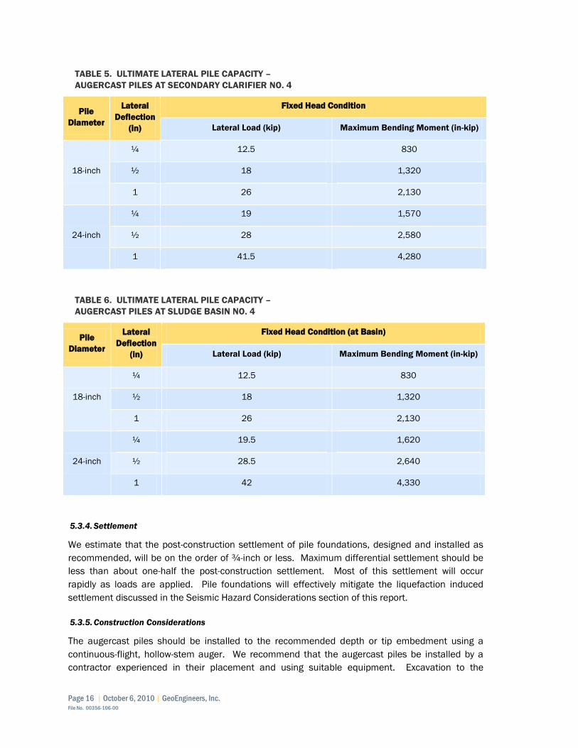
Page 16 | October 6, 2010 | GeoEngineers, Inc. File No. 00356-106-00
TABLE 5. ULTIMATE LATERAL PILE CAPACITY –
AUGERCAST PILES AT SECONDARY CLARIFIER NO. 4
Pile
Diameter
Lateral
Deflection
(in)
Fixed Head Condition
Lateral Load (kip) Maximum Bending Moment (in-kip)
18-inch
¼ 12.5 830
½ 18 1,320
1 26 2,130
24-inch
¼ 19 1,570
½ 28 2,580
1 41.5 4,280
TABLE 6. ULTIMATE LATERAL PILE CAPACITY –
AUGERCAST PILES AT SLUDGE BASIN NO. 4
Pile
Diameter
Lateral
Deflection
(in)
Fixed Head Condition (at Basin)
Lateral Load (kip) Maximum Bending Moment (in-kip)
18-inch
¼ 12.5 830
½ 18 1,320
1 26 2,130
24-inch
¼ 19.5 1,620
½ 28.5 2,640
1 42 4,330
5.3.4. Settlement
We estimate that the post-construction settlement of pile foundations, designed and installed as
recommended, will be on the order of ¾-inch or less. Maximum differential settlement should be
less than about one-half the post-construction settlement. Most of this settlement will occur
rapidly as loads are applied. Pile foundations will effectively mitigate the liquefaction induced
settlement discussed in the Seismic Hazard Considerations section of this report.
5.3.5. Construction Considerations
The augercast piles should be installed to the recommended depth or tip embedment using a
continuous-flight, hollow-stem auger. We recommend that the augercast piles be installed by a
contractor experienced in their placement and using suitable equipment. Excavation to the

October 6, 2010 | Page 17 Field No. 00356-106-00
subgrade will likely reach loose/soft soil that will easily become disturbed and may not adequately
support construction equipment without mitigation. Subgrade performance will be improved with
appropriate dewatering. Additionally, a gravel working mat about 24 inches thick, or other
measures to distribute equipment loads may be required to support equipment during pile
installation.
5.3.5.1. DRILLING AND GROUTING
The augercast piles generate cuttings as the soil is removed. As is standard practice, the pile grout
must be pumped under pressure through the hollow stem as the auger is withdrawn. Maintenance
of adequate grout pressure at the auger tip is critical to reduce the potential for encroachment of
adjacent native soils into the grout column. Grout pumps must be fitted with a volume-measuring
device and pressure gauge so that the volume of grout placed in each pile and the pressure head
maintained during pumping can be observed. A minimum grout line pressure of 100 pounds per
square inch (psi) should be maintained.
The action of the auger may tend to disturb the soil at the bottom of the drilled hole, which would
result in decreased end-bearing capacity. In order to minimize the negative effects of this
disturbance, we recommend that the pile contractor be required to rotate the auger following
pumping of the first few cubic feet of grout and prior to auger withdrawal. This will mix any loose
cuttings at the bottom of the hole with the grout; thus, developing the required end-bearing
capacity.
The glacial drift soil can have occasional cobbles and boulders and even clusters. It may be
necessary to relocate some piles if refusal is encountered above the recommended tip elevation.
5.3.5.2. AUGER WITHDRAWL
The rate of withdrawal of the auger must remain constant throughout the installation of the piles in
order to reduce the potential for necking of the piles. The rate of auger withdrawal should be
controlled during grouting such that the volume of grout pumped is equal to at least 115 percent of
the theoretical pile volume. A minimum head of 10 feet of grout should be maintained above the
auger tip during withdrawal of the auger to maintain a full column of grout and prevent hole
collapse. Failure to maintain a constant rate of withdrawal of the auger will result in immediate
rejection of that pile. Reinforcing steel for bending and uplift should be placed in the fresh grout
column as soon as possible after withdrawal of the auger. Centering devices should be used to
provide concrete cover around the reinforcing steel.
5.3.5.3. CONSTRUCTION SEQUENCING
We recommend that there be a waiting period of at least 12 hours between the installation of piles
spaced closer than 8 feet, center-to-center. This waiting period is necessary to avoid disturbing the
curing concrete in previously cast piles.
5.3.5.4. VERIFICATION AND TESTING
It should be noted that no direct information regarding the capacity of augercast piles (e.g., driving
resistance data) can be obtained while this type of pile is being installed. Therefore, we
recommend that pile installation operations be monitored by the Geotechnical Engineer or his
representative. The Geotechnical Engineer will observe the drilling operations, monitor grout
injection procedures, record the volume of grout placed in each pile relative to the calculated
Page 18 | October 6, 2010 | GeoEngineers, Inc. File No. 00356-106-00
volume of the hole, and evaluate the adequacy of individual pile installations. We also strongly
recommend that a pre-construction meeting take place with the pile contractor, the owner and the
Geotechnical Engineer to discuss pile construction techniques.
Federal Highway Administration (FHWA) Geotechnical Engineering Circular No. 8 – Design and
Construction of Continuous Flight Auger Piles outlines guidelines for pre-production, verification
load testing, and integrity testing. Testing could include pre-production static load testing, rapid
dynamic test (RDT) or dynamic load test (DLT) for verification, and sonic echo testing for integrity.
In our experience, this type of testing is uncommon except for large projects or projects of a critical
nature. We recommend that this document be consulted and an appropriate testing program
selected. At a minimum, we recommend that geotechnical observations described above along
with appropriate materials testing to verify quality of grout and steel materials.
5.4. Shallow Foundation Recommendations
5.4.1. General
In general, shallow foundations will be suitable for project elements that do not impose large aerial
loads that could induce unacceptable settlement in the underlying soft soil profile. Shallow
foundations are anticipated for the Blower Building (Facility 325), CEPT Facility (Facility 240), and
other miscellaneous lightly loaded structures such as the Odor Control Equipment (Facilities 306
and 312). This may include footing design in Section 5.4.2 and Slab on Grade section 5.5. We
anticipate that these structures will be constructed near existing site grades. Based on the results
of our study, these locations are underlain by fill, alluvium and glacial drift; it does not appear that
the structures would be located in areas with peat or very soft compressible soil.
The proposed Activated Sludge Basin No. 1 (Facility 305) will also be supported on a shallow
foundation, consisting of a mat foundation and retaining walls since this structure will be
approximately 10 to 20 feet below grade. This structure is located in an area underlain at
shallower depths by dense glacial till and glacial drift. Mat foundation recommendations are
presented in Section 5.4.3 below. Some overexcavation and replacement below this structure will
be required as discussed in Section 5.4.4 below.
5.4.2. Footing Design
The subgrade soils for the at-grade foundations could be somewhat variable and will most likely
consist of existing fill from previous peat removal activities or native loose to medium dense
alluvium. Deeper foundation elements could extend through the alluvium and into the underlying
glacial drift. The lightly loaded structures as described above can be adequately supported on
spread footings or continuous foundations bearing on the native soils.
We suggest a continuous grade-beam style foundation with top and bottom steel reinforcement to
the footing together and help limit differential settlement for the Blower Building, CEPT Building, or
other structures with taller concrete tilt up or CMU walls. We suggest a minimum of 12 inches of
structural fill under shallow foundations with a contingency (because of potentially variable fill
soils) to overexcavate and replace an additional 12 inches as necessary to achieve uniform
bearing. We recommend that the slab include some steel to tie the building together, or internal
continuous footings that act as grade beams where internal footings will occur.

October 6, 2010 | Page 19 Field No. 00356-106-00
Exterior footings should be founded at least 18 inches below adjacent grade for frost protection in
accordance with local codes. We recommend that continuous wall footings and individual column
footings have minimum widths of 18 and 24 inches, respectively. Footings can be designed for an
allowable bearing capacity of 2,000 pounds per square foot (psf) for the combination of dead and
long-term live loads. This allowable bearing capacity may be increased by one-third to account for
short-term live loads such as induced by wind or seismic forces.
We recommend that all completed footing excavations be observed by geotechnical engineer prior
to reinforcing steel and structural concrete placement, to confirm that the bearing surface has
been prepared in a manner consistent with our recommendations and that the subsurface
conditions are as expected.
It may be cost effective and efficient to design the smaller odor buildings with a structural floor and
thickened edge footings as a monolithic pour. This procedure would tie the floor and perimeter
footings together and minimize differential settlement and differential movement during seismic
events.
5.4.3. Mat Foundation Recommendations
The modulus of subgrade reaction can be used for design and analysis of mat foundations that are
not supported on piles. The subgrade modulus, k, is not a fundamental soil property and depends
on many other factors including the width, shape, and depth below the ground surface of the
loaded area, position under the foundation, and time (Coduto 2001). Because it is difficult to
develop accurate k values, it may be appropriate to conduct a parametric study to evaluate its
effect on the foundation design. ACI (1993) suggests varying k from about one-half of the value to
five or ten times the value.
Mat foundations designed as beams on an elastic foundation, will require the soil subgrade
modulus for design. Where the mat foundations bear on existing fill, alluvium and/or medium stiff
glacial drift, the subgrade may be assumed to have a subgrade modulus on the order of 30 pci.
This value has been reduced to account for the soft clay soils encountered in our explorations. This
is likely the condition for the Blower Building and CEPT Building. It is likely that theses foundations
will bear on variable subgrade soils including loose sandy alluvium and soft to medium stiff clay
soils. Therefore, we recommend that these foundations be underlain by a minimum 12 inches of
sand and gravel or crushed rock as described in the “Base Preparation” section of this report. The
sand and gravel or crushed rock will serve as a clean working surface during construction.
Where mat foundations bear on dense glacial till, or compacted structural fill placed directly over
glacial till, the compacted subgrade may be assumed to have a subgrade modulus on the order of
200 pci. This condition occurs at Activated Sludge Basin No. 1.
5.4.4. Overexcavation for Selector/Activated Sludge Basin No. 1
As previously described, the eastern end of Selector/Activated Sludge Basin No. 1 will be located
on essentially incompressible glacial till and the western end of this facility is located in an area
underlain by moderately compressible glacial drift. At this time, we recommend that the glacial
drift be removed from the foundation support prism of this structure, which can be assumed by
extending a 1:1 plane out from the edge of the mat foundation to the top of the till. To limit a

Page 20 | October 6, 2010 | GeoEngineers, Inc. File No. 00356-106-00
sharp break in settlement between the structural fill and the excavation into the dense glacial soils,
we recommend that the overexcavation be transitioned over an approximately 30 foot horizontal
distance in approximately 10 foot wide and one foot high steps. The overexcavation should be
backfilled with granular structural fill compacted to at least 95 percent of the maximum dry density
(MDD) based on ASTM D 1557 test procedure as described in the Earthwork section of this report.
A generalized depiction of the foundation soils is shown in Figure 7. The depth of the glacial drift
below the foundation elevation is up to 16 feet based on the two westerly borings (GEI-10 and GEI-
13). A schematic of the overexcavation is presented in Figure 13.
It is likely that a ground improvement technique such as CDF slot trenches, CDF piles or RAPs will
be a more cost effective way to support the mat foundation. These alternatives can be evaluated
at a later time, if appropriate. As discussed previously, if the RAP option is pursued further, noise
generated during installation could be a factor for protection of adjacent wildlife habitat.
Excavated slots or piers backfilled with CDF would have construction noise similar to other planned
site activities.
5.4.5. Lateral Resistance
Lateral loads can be resisted by a combination of friction between the footing and the supporting
soil, and by the passive lateral resistance of the soil surrounding the embedded portions of the
footings. A passive lateral resistance corresponding to an equivalent fluid density of 275 pounds
per cubic foot (pcf) may be used for design above the groundwater table. Below the groundwater
table an equivalent fluid density of 150 pcf may be used. The upper 12 inches of passive
resistance should be ignored. A coefficient of friction of 0.40 may be used between the concrete
and soil. This value assumes that the subgrade soils will consist of a minimum 12-inch-thick
working surface of sand and gravel or crushed rock placed over the native site soils. These values
include a safety factor of approximately 1.5.
5.4.6. Shallow Foundation Settlement
We estimate that the post construction settlement of structures supported on shallow foundations
may be on the order of ½ to 1 inch, depending on loads and locations. Differential settlements
measured over a distance of approximately 25 feet may be on the order of 1/2 inch. We expect
that settlements for these conditions will be a combination of elastic in nature (tending to occur
rapidly after the loads are applied) and consolidation of clayey soils (tending to occur slowly over a
period of months or years).
Immediately prior to placing concrete, all debris and soil slough that accumulated in the footings
during forming and reinforcing steel placement must be removed. Debris or loose soil not removed
from the footing excavations will result in increased settlement.
5.5. Slab-On-Grade Support
The slab subgrade soils for the near surface structures should be prepared in accordance with the
site preparation recommendations provided in the “Earthwork” section of this report. We
recommend that the exposed slab subgrades be compacted to a firm and non-yielding condition
and approved by the geotechnical engineer during construction. We recommend that the slab-on-

October 6, 2010 | Page 21 Field No. 00356-106-00
grade be supported on a layer of structural fill serving as capillary break material with a minimum
thickness of 12 inches for the structures.
The capillary break material should consist of a well-graded sand and gravel or crushed rock with a
maximum particle size of 1 inch and have less than 3 percent fines. A suitable WSDOT Standard
Specification is coarse aggregate for Portland cement concrete, AASHTO Grading No. 67
[9-03.1(4)C].
Where moisture content in the slab is critical (i.e., if tile or carpeting is glued to the slab), we
recommend a vapor barrier be placed between the floor slab and the capillary break material. The
vapor barrier should consist of polyethylene sheeting with bonded seams.
All fill placed beneath the building slab to meet the proposed grade should be in accordance with
our recommendations for structural fill provided in the “Earthwork” section of this report.
Structural fill in slab areas should be compacted to at least 95 percent of the MDD in accordance
with ASTM D 1557.
5.6. Additional Design for Below Grade Structures
The Secondary Clarifier No. 4 (Facility 330), Activated Sludge Basin No. 4 (Facility 311), and
Activated Sludge Basin No. 1 (Facility 305) will have below grade portions of the structure that will
be subject to lateral earth pressures, hydrostatic pressures, buoyancy and uplift.
5.6.1. Lateral Earth Pressures
Lateral soil pressures acting on the retaining walls will depend on the nature and density of soil
behind the wall, the amount of lateral wall movement which occurs as backfill is placed, and the
inclination of the backfill surface. For walls free to yield at the top at least one thousandth of the
wall height (i.e., wall height times 0.001), soil pressures will be less than if wall movement is
restrained. We recommend that walls free to yield at the top and supporting horizontal backfill be
designed using an equivalent fluid density of 35 pcf. We recommend that walls deeper than 5 feet
bgs be designed using an equivalent fluid density of 80 pcf to account for hydrostatic pressures. If
the walls will be restrained against movement, we recommend using an equivalent fluid density of
55 pcf above the water table and 90 pcf below the water table. We conclude that the
Selector/Activated Sludge Basin No. 1 does not need to be designed with hydrostatic earth
pressures (based on the proposed base Elevation of 14 feet) provided that the design includes a
drainage layer with positive drainage by gravity or sump and pump.
We also recommend a uniformly distributed seismic surcharge of 9H psf (H = Height of wall) be
applied to the wall with a corresponding reduction in the factors of safety to 1.1 or greater. Lateral
pressure resulting from seismic surcharge loading is additive to lateral soil pressures computed as
recommended above. Surcharge loading should be added to all walls where appropriate. If traffic
can be within about 10 feet of the top of the wall, we recommend that the walls be designed for a
250 psf surcharge load. For design purposes, this is equivalent to assuming approximately two
additional feet of soil above site grades using the equivalent fluid densities described above.
Temporary surcharge loading during construction resulting from equipment and soil stockpiles
should be evaluated by the contractor.

Page 22 | October 6, 2010 | GeoEngineers, Inc. File No. 00356-106-00
In order to prevent overstressing the concrete retaining walls and causing bulging or rotation, we
recommend that structural fill placed against the back of the wall be compacted with lighter weight
hand-operated equipment and within the range of 90 to 92 percent of the MDD. Backfill should be
placed after the concrete has had sufficient time to cure and develop the necessary strength.
5.6.2. Buoyancy and Uplift
We recommend that the structures that extend below the groundwater table be designed to resist
hydrostatic uplift, based on a groundwater level at Elevation +12 feet for the Secondary Clarifier
No. 4 (Facility 330) and +15 feet for the Sludge Basin No. 4 (Facility 311). The Activated Sludge
Basin No. 1 (Facility 305) is located in an area almost exclusively underlain by glacial till and glacial
drift. This effectively is a boundary condition for the groundwater conditions in the alluvium and we
conclude that this structure does not need to be designed for buoyancy or uplift; however, we
recommend positive drainage below the basin. Without drainage provisions, the excavation
backfill could have the potential to collect water in the lower permeability native soil “bathtub”.
This basin could alternatively be designed for hydrostatic uplift based on a groundwater level at
about Elevation +17 feet.
Resistance to uplift can be developed by the dead weight of the structure, friction along the sides
of the structure, and pile side friction where pile foundations are used. Frictional resistance can be
computed using a coefficient of friction of 0.35 applied to the lateral soil pressures. This
coefficient of friction is an allowable value and includes a factor of safety of approximately 1.5. We
recommend that lateral soil pressures for uplift resistance be computed using an equivalent fluid
density of 35 pcf above the groundwater table and 18 pcf below the groundwater table. In addition
to the above means of resisting uplift, the structure may be constructed with a base that extends
beyond the structure walls so that the weight of overlying soil resists a portion of the uplift. For this
purpose the overlying backfill may be assumed to have a submerged unit weight of 60 pcf.
5.6.3. Drainage for Activated Sludge Basin No. 1 (Facility 305)
The Activated Sludge Basin No. 1 site is located in an area underlain by glacial till and glacial drift.
The only water encountered in this area was perched within a thin veneer of fill overlying these
relatively impermeable soil units. We recommend that this basin be underlain by at least 1 foot of
free draining sand and gravel (such as Gravel Backfill for Walls, Washington State Department of
Transportation Standard Specification (hereafter referred to as WSDOT Standard Specifications)
Section 9-03.12(2)) or washed gravel. Depending on conditions encountered during construction,
a perimeter footing drain may also provide suitable drainage. We recommend that the subgrade
be graded toward a sump with a pump or a gravity drain. Without drainage provisions, the
structure should be designed for hydrostatic uplift as described above.
5.6.4. Buried Slabs
Buried slabs, such as for the tops of utility vaults or tunnel roofs, should be designed for a uniform
pressure of 130 psf per foot of fill placed above the slab. Other loading, such as traffic surcharge
should also be applied to these slabs.

October 6, 2010 | Page 23 Field No. 00356-106-00
5.7. Pipe Design Considerations
5.7.1. General
Various piping and utility corridors will be required to connect the new facilities to the existing
infrastructure. Notable utilities include new piping that will connect the Activated Sludge Basin
No. 1 and Activated Sludge Basin No. 4 in the southeast portion of the site. This piping will include
three 48-inch diameter pipes and one 72-inch diameter pipe, all with inverts generally ranging
between about Elevation 0 feet and 5 feet. Reinforced concrete pipe (RCP) will be used for these
installations.
Within the areas of identified peat removal, variable quality structural fill could be encountered.
Where piping extends outside of the identified areas of peat removal, there is a possibility that peat
will be encountered, particularly in the western portion of the site. The groundwater table, or zones
of groundwater seepage, will likely be encountered at relatively shallow depths throughout the site.
The contractor should anticipate, at a minimum, all utility excavations will require a trenchbox for
sidewall support and sumps and pumps to control groundwater seepage. At some locations, where
nearby infrastructure must be protected, shoring that limits lateral movement of soil and more
aggressive dewatering, as described in this report, may be necessary.
The work areas should be cleared of all surface and subsurface deleterious matter, including
debris, vegetation and root wads; and stripped of any organic soil, if present. The cleared/stripped
material will not be suitable for use as structural fill, which includes trench backfill.
5.7.2. Pipeline Support
Because of the variable geologic conditions and site history, the soils expected to be encountered
at the subgrade level will be highly variable depending on location at the site, pipe depth, previous
overexcavation of peat soils, and other factors. In general, the native alluvium, glacial drift, glacial
till, and most previously placed fill will provide adequate support for proposed piping throughout
the site. If the subgrade soils are organic, become disturbed, or are otherwise unsuitable, it may
be necessary to over-excavate the unsuitable material and backfill with pipe bedding or crushed
surfacing material as discussed below. Portions of the site piping may be below the groundwater
table. In these cases, we recommend that dewatering occur prior to excavation as discussed
subsequently in this report.
We recommend a minimum of 12 inches of foundation material be placed for leveling and support
of new piping. Depending on conditions encountered it may be helpful to place a geotextile fabric
as separation between the native subgrade and foundation imported material. Based on the
explorations general recommendations for pipe bedding support are presented below:
■ Pipe bedding material, placement, compaction, and shaping should be in accordance with
the project specifications, the pipe manufacturer’s recommendations, and Section 7-09 of
the most recent WSDOT Standard Specifications. At a minimum, the pipe bedding should
meet the gradation requirements for Gravel Backfill for Pipe Zone Bedding Section
9-03.12(3) of the Standard Specifications, unless otherwise stated by the project
specifications.

Page 24 | October 6, 2010 | GeoEngineers, Inc. File No. 00356-106-00
■ If the trench bottom encounters any extremely soft or organic-rich subgrade soils, it may be
necessary to over-excavate the unsuitable material and backfill with pipe bedding material.
In wet conditions, 1½-inch minus granular fill meeting the gradation requirements for
Gravel Backfill for Pipe Zone Bedding, as previously described, should be used to backfill
the over-excavated portion of the trench.
■ Pipe bedding material should be used as backfill up to at least the spring line of the pipe or
in accordance for with the WSDOT standard plans for the type of pipe chosen.
■ Prior to the installation of the pipe, the pipe bedding should be shaped to fit the lower part
of the pipe exterior with reasonable closeness to provide continuous support along the
pipe.
■ Pipe bedding material and/or backfill around the pipe should be placed in layers and
tamped around the pipe to obtain complete contact per the project plans. In areas where
a trench box is used, the bedding material should be placed before the trench box is
advanced.
■ We understand that the large diameter RCP described above will be bedded in flowable
CDF to ensure full support of the pipe. The CDF will be backfilled to about 1 foot above the
crown of the pipe bell. In our opinion this will provide suitable bedding for the pipe. If very
soft or organic subgrade soils are encountered, it may be necessary to first stabilize the
subgrade as described above prior to placing the pipe or CDF bedding, or an initial lift of
CDF can be use as a base stabilization.
5.7.3. Structural and Trench Backfill
We recommend that trench backfill consist of structural fill as described in the subsequent
earthwork section of this report. The suitability of the native, on-site material as structural fill is
discussed below. During placement of the initial lifts, the backfill material should not be bulldozed
into the trench or dropped directly on the pipe. Furthermore, heavy vibratory equipment should not
be permitted to operate directly over the pipe until a minimum of 2 feet of backfill has been placed.
Backfill should be placed in lifts to achieve the required compaction using the mechanical
equipment chosen by the contractor. We recommend that the MDD be determined based on ASTM
D 1557 or in accordance with WSDOT Standard Specification 2-03.3(14)D.
■ In non-settlement sensitive areas, such as landscape areas, we recommend that the backfill
be compacted to at least 85 percent of its MDD.
■ In settlement sensitive areas, such as existing or future roadways and driveways, backfill
placed at depths greater than 2 feet below the ground surface should be compacted to at least
90 percent of the MDD. The upper 2 feet of backfill should be compacted to at least
95 percent of the MDD in existing/future pavement areas. This is consistent with Method B of
WSDOT Standard Specification 2-03.3(14)C.
5.7.4. Pipe Settlement
The likely mechanisms for pipe settlement are from poor bearing support immediately below the
pipe, consolidation of underlying compressible soils under new loads, or liquefaction induced
settlement. For smaller diameter and shallower pipes, the increased weight of the structural
backfill will be negligible and will not lead to significant settlement. Structural backfill for the large
diameter RCP trenches will be heavier than the native site soils; however, the increased weight will

October 6, 2010 | Page 25 Field No. 00356-106-00
be partially offset by the pipe voids/difference in weight between pipe contents and soil. The net
increase will be low, such that settlement from increased soil stress will be on the order of ½ to ¾
inch or less. If settlement in this range is unacceptable, the increased loading and resulting
settlement could be reduced by backfilling with clean uniform sand, with MDD on the order of 100
pcf.
The design and construction procedures discussed in this report will not mitigate the possible
liquefaction effects and associated damage to the utilities caused by differential settlements.
Infrastructure supported by or within liquefiable zones is at higher risk, however, oftentimes buried
pipes will move with the soil and not experience significant damage. The proposed CDF backfill will
increase the likelihood that the pipe will move as a unit and reduce differential settlement over
short distances along the pipe length. The pipeline/infrastructure areas at most significant risk are
transitions from non-liquefiable soils to liquefiable areas (such as transitions from the dense glacial
till near Aeration Basin No. 1 to areas of alluvium) and transitions of liquefiable areas to pipe
supported structures (such as pipes connected to Secondary Clarifier No. 4 and Aeration Basin No.
4). The most significant design issue in this regard is the piping transitions.
In order to minimize the risk of potential damage from liquefaction from a large design event, it
would be necessary to support the utilities on piles or improve the ground such that the soils below
the corridor do not liquefy. However, in our experience, these measures are not considered
feasible for this type of project because of the significant expense. The simplest and most cost-
effective mitigation strategy is to include restrained joints (which allow movement but not
separation) and flexible connections at these risk areas, although some of the piping for this
project is likely too big for flexible connections. It may not even be practical/possible to completely
mitigate the large scale differential movements from a large design event; however, some flexibility
will provide resistance to smaller earthquakes.
5.8. Corrosion Potential
Corrosion potential of soil samples selected by Carrollo Engineers was conducted based on
laboratory chemical testing subcontracted to ALS Group of Everett, Washington. Laboratory testing
included pH, chloride, sulfate, sulfide, redox potential, and resistivity, the results of which are
summarized in Table7 below, with the full laboratory results presented in Appendix B. The results
of the chemical testing were compared to critical values presented in FHWA-RD-89-186 (FHWA
1990) for evaluating aggressiveness of soil environment for steel reinforcement.
TABLE 7 – RESULTS OF LABORATORY TESTING FOR CORROSION POTENTIAL
Boring
No.
Sample No.
(Depth) pH
Chloride
(mg/kg)
Sulfate
(mg/kg)
Sulfide
(mg/L)
Redox
Potential
(mV)
Resistivity
(Ohm/cm)
GEI-2 S-5
(15’) 7.2 180 340 ND 480 2500
GEI-4 S-3
(7.5’) 8.3 32 410 ND 400 6500

Page 26 | October 6, 2010 | GeoEngineers, Inc. File No. 00356-106-00
GEI-6 S-4
(10’) 7.5 23 190 ND 380 4350
GEI-9 S-4
(10’) 7.7 21 190 ND 380 4350
Based on the referenced document, soils with a redox potential between 380 to 480 mV are
considered slightly to non-corrosive. Soils with a resistivity between 2,500 and 6,500 ohm/cm are
considered moderately to mildly corrosive. The same document presents the following
recommended electrochemical limits for fill soils:
pH greater than 4.5 and less than 9.5
chlorides less than 100 ppm
sulfates less than 200 ppm
resistivity greater than 5,000 ohm/cm
Based on these limits, all the samples tested have at least some limited corrosion potential to steel
reinforcement. We recommend further corrosion evaluation during final design.
5.9. Earthwork
5.9.1. General
Significant excavation will be required for the proposed improvements at the site. Temporary
shoring is anticipated to reduce dewatering requirements. The site soils that will be excavated
generally consist of various fill soils, loose to medium dense silty sand (alluvium), medium stiff silt
and clay (glacial drift), and dense silty sand and gravel (glacial till). These are moisture-sensitive
soils and are susceptible to disturbance by construction equipment during wet weather. We expect
that stormwater would be contained in the excavations, especially after the sheet pile wall is
installed.
Temporary erosion control measures should be used during construction depending on the water,
location, soil type and other factors. Temporary erosion protection (for example, straw, plastic or
rolled erosion control products [RECPs]) may be necessary to reduce sediment transport until
vegetation is established or permanent surfacing applied. Appropriate best management practices
(BMPs) should be incorporated into the temporary erosion and sediment control plan developed by
the civil engineer. We are available to provide input if requested.
5.9.2. Site Preparation
The proposed improvements will be constructed in areas currently surfaced with field grass, small
trees/shrubs, gravel, and pavement. We recommend that any existing vegetation and topsoil or
other surfacing be stripped from all new building and pavement areas. For planning purposes, the
results of our explorations indicate stripping depth in vegetated areas within the existing facility will
be in the range of 3 to 6 inches, and outside the existing WWTP footprint, in the range of 12 to
24 inches. Roots should be grubbed to a diameter less than 1 inch. The stripped material should
be wasted off-site. We recommend that the existing pavement be removed from the existing

October 6, 2010 | Page 27 Field No. 00356-106-00
driveway area where necessary and a uniform subgrade be prepared in all areas for support of the
new pavement section.
The prevailing site soils are moisture-sensitive and will be difficult to operate on and very difficult to
compact during wet weather. Rubber-tired vehicles can easily disturb this type of soil. It has
moderate erosion potential in-place and is easily transported by running water when disturbed.
Therefore, silt fences and other measures will be necessary to control erosion and sediment
transport during construction.
We recommend that the subgrade be evaluated by a representative of GeoEngineers to confirm the
subgrade is adequate for structural support. After site preparation activities have been completed
in pavement areas, we recommend that the subgrade for structural areas be thoroughly proofrolled
with heavily loaded rubber-tired construction equipment if site preparation is done during extended
dry weather conditions. The proofrolling should be observed by one of our geotechnical engineers,
who will evaluate the subgrade. In areas where adequate compaction cannot be achieved,
additional overexcavation of soft, organic or deleterious materials may be required as directed by
the field engineer.
5.9.3. Base Preparation
The base of Secondary Clarifier No. 4 and Activated Sludge Basin No. 4 excavations will be
disturbed, wet and very soft and difficult to work on. The subgrade soils for the at-grade
foundations could be somewhat variable and will most likely consist of existing fill from previous
peat removal activities or native loose to medium dense alluvium. We therefore recommend that a
minimum 12 inch layer of clean sand and gravel (Select Import Fill as described in this report) be
placed over the subgrade, however a thicker layer, up to 24 inches, or other means of distributing
equipment loads, may be required to support pile installation equipment.
For pile supported mat foundations we recommend that the sand and gravel be uniformly
compacted with a smooth drum roller to at least 90 percent of the MDD in accordance with
ASTM D 1557 or in accordance with the geotechnical field engineer’s recommendations. For
conventional shallow mat foundations and footings we recommend that the structural fill be
compacted to at least 95 percent of the MDD. We also recommend placing a lightweight
nonwoven geotextile fabric (e.g., Mirafi 140NS, Layfield LP4) between fine-grained subgrades soils
and the imported material to help subgrade performance and minimize intrusion of the medium
stiff silt/clay subgrade soils. It will likely be necessary to install a series of sumps through the sand
and gravel and into the underlying material to capture and pump groundwater and rainwater that
will flow into the excavation through the sheet pile joints.
5.9.4. _Temporary Excavations
All excavation activities must be completed in accordance with applicable county, state and federal
safety standards. The on-site soils can generally be excavated using conventional earthmoving
equipment, although some large cobbles should be expected. Excavation of the glacial till in the
eastern portion of the basin will encounter very dense soil that may be very difficult to excavate
and require larger equipment or “ripping” to reach the proposed subgrade elevation. Regardless of
the soil type encountered in the excavation shoring, trench boxes, or sloped sidewalls will be
required for excavations deeper than 4 feet under Washington State Administrative Code (WAC)

Page 28 | October 6, 2010 | GeoEngineers, Inc. File No. 00356-106-00
296-155, Part N. The stability of open-cut slopes is a function of soil type, groundwater level, slope
inclination and nearby surface loads. The use of inadequately designed open cuts could impact
the stability of adjacent structures and existing utilities and endanger personnel. We expect that
much of the trench excavations will be made as open cuts in conjunction with the use of sloped
sidewalls and/or a trench box for shielding workers.
The stability of open-cut slopes is a function of soil type, groundwater level, slope inclination and
nearby surface loads. The use of inadequately designed open cuts could impact the stability of
adjacent roadway surfaces, nearby structures and existing utilities, and endanger personnel. In our
opinion, the contractor will be in the best position to observe subsurface conditions continuously
throughout the construction process and to respond to variable soil and groundwater conditions.
Therefore, we recommend that the contractor have the primary responsibility for deciding whether
or not to use an open-cut slope rather than some form of temporary excavation support and/or
dewatering strategies. Temporary excavation considerations for the various project elements are
discussed below:
■ We expect that excavations for the Secondary Clarifier No. 4 and Activated Sludge Basin No. 4
will not remain open below the groundwater table absent significant dewatering. The saturated
loose to medium dense sand will run into the excavation. It is our opinion that aggressive
dewatering will be required while the excavation is open. Alternatively, a cutoff wall (such as a
continuous sheetpile cofferdam) extending a minimum of 10 feet into the underlying clayey
glacial drift would effectively cut off the groundwater allowing conventional sumps and pumps
dewatering inside the cofferdam.
■ Soil and groundwater conditions within the areas of previous peat removal could be extremely
variable. If significant quantities of clean granular fill were used as backfill, groundwater flow
into excavations could be rapid. Groundwater seepage may also occur where layers/lenses of
granular material occur within finer grained fill.
We suggest that the contractor “pothole” the areas of excavation and alignment of the utility
trenches in advance of opening the excavation to put an excavation strategy/dewatering plan
together as appropriate. Dewatering considerations are provided in a subsequent section of
this report.
5.9.5. Temporary Cut Slopes
The state regulations allow temporary slopes for excavations less than 20 feet deep, from
0.75H:1V (Horizontal:Vertical) to 1.5H:1V depending upon soil type. The regulations assume that
surface loads such as construction equipment and storage loads will be kept a sufficient distance
away from the top of the cut so that the stability of the excavation is not affected. Based on our
explorations, the site soils are considered to be as follows:
■ The existing fill and loose to medium dense granular alluvial soils are considered to be a “Type
C” soil by the regulations, which has an allowable temporary maximum slope angle of 1.5H:1V.
■ The soft clay (glacial drift) is considered to be a “Type B” soil by the regulations, which has an
allowable temporary maximum slope angle of 1H:1V.
■ The medium stiff to stiff glacial drift dense glacial till is considered to be a “Type C” soil by the
regulations, which has an allowable temporary maximum slope angle of 0.75H:1V.

October 6, 2010 | Page 29 Field No. 00356-106-00
The regulations and maximum slope angles presented assume that groundwater seepage is not
present in these soils. Therefore, the soils must be above the groundwater level and/or in a
dewatered condition.
If temporary cut slopes experience excessive sloughing or raveling during construction, it may
become necessary to modify the cut slopes to maintain safe working conditions and protect
adjacent facilities or structures. Slopes experiencing excessive sloughing or raveling can be
flattened, regraded to add intermediate slope benches, or additional dewatering can be provided if
the poor slope performance is related to groundwater seepage. Berms, hay bales or other
provisions should be installed along the top of excavations to intercept surface runoff to reduce the
potential for sloughing and erosion of cut slopes during wet weather.
5.9.6. Temporary Shoring – Trench Boxes
We recommend that a shoring system be used where excavations are located adjacent to existing
utilities, roadways or structures where soil movement or ground loss could result in damage to
these facilities. Generally, a trench box is not considered appropriate in areas where soil
movement adjacent to the trench is unacceptable. Typically, a trench box is used to protect
workers from injury should the sidewall collapse. If a sidewall collapses, a contractor typically will
backfill the void space in the trench box to the extent practical. Upon completion of the work the
contractor will then pull the trench box out and the sidewalls cave and surface distress or
disruption occurs.
A trench box can be used where sidewall support is required provided that it is (1) designed for
anticipated earth pressures and hydrostatic pressures if appropriate and (2) the installation,
moving and backfilling can be accomplished in such a manner that significant yielding does not
occur. Braced or unbraced shoring (several types of adjustable braced trench shoring systems are
available) of various types could be used where protection of existing infrastructure is necessary.
If a trench box is used and the soils are dewatered below the base of the excavation (prior to
excavation), yielding/movement of the sidewalls is unlikely to occur beyond a 1.5H:1V slope as
measured from the bottom of the excavation. If the soils are not dewatered to at least 1 foot below
the bottom of the trench prior to and during excavation, the area of disturbance could be
significantly greater. The following should be implemented for the shoring systems for the project:
■ At locations where settlement could be detrimental to adjacent structures, utilities, or
pavements, the shoring system should be designed to prevent significant lateral movement of
the existing soils.
■ Precautions should be taken during removal of the shoring or sheeting materials to minimize
disturbance of the pipe, underlying bedding materials, and natural soils.
■ Trench boxes should be of sufficient size, both vertically and horizontally, to support the
excavation without excessive deformation of the natural soils.
■ The open excavations should be backfilled as soon as practical after the shoring has been
removed.

Page 30 | October 6, 2010 | GeoEngineers, Inc. File No. 00356-106-00
■ Heavy construction equipment, construction materials, and excavated soil should not be
allowed within a distance, measured from the edge of the excavation, equal to half the depth
of the excavation, unless the shoring system has been designed for the additional lateral
pressure.
Because of the diversity of available shoring systems and construction techniques, the design of
temporary shoring is most appropriately left up to the contractor proposing to complete the
installation. We recommend that the shoring be designed by an engineer licensed in Washington,
and the PE stamped shoring plans and calculations be submitted to the engineer prior to
construction.
5.9.7. Temporary Shoring – Sheet Pile Walls
5.9.7.1. GENERAL
We anticipate that construction of the Secondary Clarifier No. 4 (Facility 330) and Activated Sludge
Basin No. 4 (Facility 311) will be completed using a shored excavation due to the depth of the
excavation and the presence of groundwater. A sloped excavation may be feasible at some
locations provided that aggressive dewatering is completed concurrently and space constraints will
not prohibit relatively flat temporary slopes. A sheet pile system extending into the underlying
clayey glacial drift at the site will retain the soils and serve as a groundwater cutoff to minimize the
quantity of water that will need to be pumped and discharged. For deeper excavations, where the
wall is greater than about 10 feet high, it may be necessary to use a row of tieback anchors or
deadmen to resist the additional pressure due to hydrostatic pressures. We recommend that the
shoring be designed by an engineer licensed in Washington, and the PE stamped shoring plans and
calculations be submitted to the Engineer prior to construction. The following paragraphs present
suggested design parameters based on conditions encountered at the site; however, as stated
before, the contractor will be responsible for shoring design.
5.9.7.2. SHEET PILE DESIGN PARAMETERS
The soil conditions encountered within our explorations generally consist of existing fill and
alluvium with some remaining peat overlying generally clayey glacial drift. Groundwater is assumed
to be approximately Elevation 12 feet near the Secondary Clarifier No. 4, and approximately
Elevation 15 feet near the Sludge Basin No. 4. Our preliminary analysis indicate that that the
loose/soft soil profile may not be capable of supporting tall cantilever sheet pile walls and that tie-
back anchors or deadmen may be required for excavations greater than about 10 feet.
Earth pressure diagrams for sheet pile shoring are provided in Figure 14 for the Secondary Clarifier
No. 4 for areas inside the previous peat removal area (Case 1) and for areas outside the previous
peat removal area (Case 2). Earth pressure diagrams for sheet pile shoring are provided in Figure
15 for the Activated Sludge Basin No. 4 (Case 3).
5.9.8. Structural Fill
Structural fill materials should be free of debris, organic contaminants and rocks or rock fragments
larger than 6 inches or half the lift thickness, whichever is smaller. All fill placed within the building
and pavement areas should be placed as structural fill. Structural fill should be placed in
horizontal lifts not exceeding 10 inches in loose thickness or that necessary to obtain the specified

October 6, 2010 | Page 31 Field No. 00356-106-00
compaction with the equipment used. Each lift must be thoroughly and uniformly compacted as
previously recommended.
As the amount of fines (material passing the U.S. No. 200 sieve) increases in a soil it becomes
more sensitive to small changes in moisture content. During wet conditions, adequate compaction
becomes more difficult to achieve. Generally, soils containing more than about 5 percent fines by
weight cannot be properly compacted when the moisture content is more than a few percent from
optimum.
Sufficient earthwork monitoring and a sufficient number of in-place density tests should be
performed to evaluate fill placement and compaction operations and to confirm that the required
compaction is being achieved.
5.9.8.1. Suitability of On-Site Materials
The on-site materials within much of the proposed excavation depth for below grade structures
consist fill of variable composition including sand, silt and clay, with limited quantities of cleaner
sand (SP-SM and SP). Material excavated from below the water table will not be suitable for use as
backfill unless the sand is allowed to drain. The fine-grained soils encountered during our
explorations typically had a moisture content well above the optimum moisture content. Since
these soils are highly moisture sensitive and have a high natural water content, it will be very
difficult to compact these soils to dry densities greater than 90 percent of the MDD as specified.
Therefore, we recommend that the silt and clay be considered not suitable for use as structural fill.
Silty sand fill and native soils (including glacial till), encountered during our explorations had
moisture contents ranging from slightly above, to well above optimum moisture content. This
material is also highly moisture sensitive. In our opinion the silty sand encountered may be used at
the time of construction if approved by the geotechnical engineer based on the field moisture
content and intended use. If significant quantities of native or previously imported sand with silt
(SP-SM) or sand (SP) are encountered, this material will likely be suitable for general backfill. This
material will likely need to be moisture conditioned to achieve suitable compaction. It may be
necessary for the contractor to segregate materials in order to use on-site soils for backfill. For
planning purposes in structural support areas, we recommend a select import fill where structural
fill is required.
5.9.8.2. SELECT IMPORT FILL
If wet weather or the moisture content precludes the use of onsite materials structural fill, we
recommend using a select import fill to complete the backfilling site excavations. The select import
fill should consist of sand and gravel with a fines content less than 5 percent based on that portion
passing the ¾-inch sieve. Suitable Standard Specifications include Gravel Borrow (9-03.14).
5.9.9. Wet Weather Earthwork and Erosion Control
General recommendations relative to earthwork performed in wet weather or in wet conditions are
presented below. These recommendations should be incorporated into the contract specifications.
■ Earthwork should be performed to limit exposure to wet weather. Excavation or the removal of
unsuitable soil should be followed promptly by the placement and compaction of clean fill. The
size and type of construction equipment used may need to be limited to prevent soil
disturbance.

Page 32 | October 6, 2010 | GeoEngineers, Inc. File No. 00356-106-00
■ The ground surface within the construction area should be sealed by a smooth drum vibratory
roller, or equivalent, and under no circumstances should soil be left uncompacted and exposed
to moisture that can erode off the jobsite.
■ Excavation and placement of structural fill and trench backfill material should be performed
under sufficient observation and testing to confirm that the work is completed in accordance
with the project specifications and the recommendations contained herein.
■ Soil stockpiles should be covered with plastic sheeting if wet weather conditions are
anticipated.
■ Silt fences should be installed between the work area and sensitive areas to prevent transport
of sediment beyond the work area.
5.10. Construction Dewatering
5.10.1. General
The excavations for the Secondary Clarifier No. 4, Activated Sludge Basin No. 4, and some
excavations for utility piping will likely be below groundwater during most times of the year. Zones
of seepage will likely be encountered in other shallower excavations and for excavation of the
Activated Sludge Basin No. 1. As discussed previously, we recommend sheetpile shoring/cutoff
walls be considered for Clarifier No. 4 and Sludge Basin No. 4 excavations to limit dewatering
requirements. Where temporary construction slopes with open cuts will be used, we expect that a
combination of open pumping, pumped wells, and/or well points will be required to adequately
dewater site soils. Deep wells will not provide efficient dewatering based on the typical conditions
of limited thicknesses of more granular soils overlying clay. It is likely that sumps and pumps with
limited shoring will be sufficient to dewater if the water level needs to be lowered only a few feet.
Extensive dewatering of compressible soils can increase effective stresses in the soil and induce
settlement.
The Contractor should have the responsibility to determine the dewatering measures needed for
the project. The monitoring wells installed are still in place and we expect will be available for
additional monitoring during the design for the project and by the contractor prior to construction.
A general discussion of the dewatering methods anticipated for the project is discussed below.
5.10.2. Open Pumping
This dewatering method involves removing water that has seeped into the excavation by pumping
from a sump that has been excavated at one end of the excavation or trench. Drainage ditches
that are connected to the sump are typically excavated along the sidewalls at the base of the
excavation or trench. The excavation for the sump and the drainage ditches should be backfilled
with gravel or crushed rock to reduce the amount of erosion and associated sediment in the water
pumped from the sump. In our experience, a slotted casing, perforated 5-gallon bucket or
55-gallon drum that is installed in the sump backfill provides a suitable housing for a submersible
pump.
The amount of water removed from the excavation by open pumping should be minimized because
of high turbidity levels. Temporary storage of dewatering effluent from the sumps in a settlement
tank or basin may be required to meet NPDES construction storm water discharge permit
requirements and reduce sediment content prior to discharging the water to surface water courses.

October 6, 2010 | Page 33 Field No. 00356-106-00
5.10.3. Pumped Wells
Pumped wells that have been properly installed and developed in highly permeable sand deposits
are capable of producing the high discharge rates that are necessary to dewater these coarse
grained units. Pumped wells are generally the most effective dewatering method in areas where
dewatering to deeper than about 15 feet below the ground surface is necessary. In our opinion,
pumped wells will have limited effectiveness in most areas of the site due to the relatively high
fines content of the most of the site soils and underlying unit clayey glacial drift.
We recommend that all dewatering wells installed for this project be properly developed to remove
fine sediment from the immediate vicinity of the well screens. Proper development is essential for
producing efficient wells and greatly reduces the turbidity of the water discharged from the well.
Filter packs consisting of properly graded sand, should be installed around the well screens in
areas where the aquifer contains a high percentage of fine sand and silt.
5.10.4. Wellpoints
Wellpoints are effective for dewatering all types of soils, whether pumping small amounts of water
from silt or large quantities of water from coarse sand and gravel. The volume of water generated
by a wellpoint system is typically less than the volume generated by a corresponding system of
pumped wells because the wellpoints are generally completed at a shallower depth. Because of
the shallower completion depth, the volume of aquifer that contributes water to a wellpoint system
is less than for a comparable deep well system. In our opinion, well points will be a more effective
dewatering system than pumped wells, given the site conditions.
Wellpoint systems are most suitable for dewatering shallow excavations where the water table
must be lowered no more than about 15 feet below ground surface or the header surface. Multiple
wellpoint stages are generally required beyond that depth because of the physical limitations of
suction lift. Dewatering can be accomplished at depths greater than 15 feet where the excavation
can be open cut to permit installation of the wellpoint header system below original grade. This
technique increases the depth to which the water table can be lowered with wellpoints.
The wellpoints would likely need to be installed on less than 10-foot centers (typically 4 to 8 feet) to
be effective and as close as possible to the edge of the excavation. The wellpoint screens should
be filter packed with graded sand, or sand and fine gravel to improve pumping efficiency and
minimize the discharge of turbid water. Wellpoints must be sealed to a depth of at least 8 feet with
hydrated bentonite chips forming a surface seal to encourage the development of a partial vacuum
around each wellpoint.
5.10.5. Dewatering Qualifications and Experience
We strongly recommend that dewatering, where used, be performed by a contractor or
subcontractor with dewatering experience. If necessary to use well points, we recommend an
experienced dewatering specialist contractor with competent and experienced staff who can
demonstrate successful deployment and operation of vacuum wellpoint systems in the Pacific
Northwest over the past 10 years, and who can install systems that use high capacity electronically
controlled and monitored vacuum pumps. If active dewatering using wells or wellpoints will be
used, we recommend a Dewatering Plan be required as a submittal from the contractor at least

Page 34 | October 6, 2010 | GeoEngineers, Inc. File No. 00356-106-00
two weeks prior to dewatering, that fully describes the dewatering approach, including material and
equipment specifications, calculations and supporting assumptions to ensure that dewatering is
achieved to not less than 1 foot below excavation subgrade. The Dewatering Plan should include
an appropriate survey program identifying critical infrastructure that will be monitored, schedule of
survey times, and appropriate action plans if subsidence is observed. The Dewatering Plan should
be prepared by or under the direct supervision of a Professional Engineer and/or Licensed
hydrogeologist registered in the State of Washington and having at least 5 years of demonstrated
experience in the design and operation of vacuum wellpoint dewatering systems.
5.10.6. Dewatering Limitations
Our services were provided to assist in the assessment of construction dewatering requirements
for the planned wastewater treatment plant expansion project. Our dewatering recommendations
are based on evaluation of the available geotechnical information. Groundwater can create a
safety threat and can seriously compromise arrangements for shoring excavations. Also, given the
potential for natural variation in geologic formations, differing site conditions may be encountered
that could lead to substantially different groundwater inflows and dewatering challenges than are
presented in this evaluation. We did not perform pumping tests or other detailed hydrogeologic
evaluations and this information is presented for use by the contractor but is not intended to
dictate designs.
5.11. Pavement
New pavement will be constructed primarily as driveways and access roads for the proposed
facilities. The access roads will typically support lightweight traffic; however, larger equipment or
trucks will also use the driveways occasionally. Accordingly, we recommend a minimum pavement
section consisting of the following layers in new pavement areas:
■ 3 to 4 inches of AC surface course. It is our opinion that 4 inches of AC will better support the
construction traffic. The surface course may consist of either of the following mix designs:
Hot Mix Asphalt (HMA), Class ½ inch, PR 64-22 per the most recent WSDOT Standard
Specifications (5-04 and 9-03.8) for the ESAL interval from 0.3 to 3 million;
Class B Asphalt Concrete per the 2002 WSDOT Standard Specifications (5-04 and 9-03.8).
■ 4 inches of crushed surfacing base course per WSDOT Standard Specifications 9-03.9(3).
■ 12 inch thick subbase course consisting of gravel base (WSDOT Standard Specifications,
9-03.10). We recommend the base course have at least 30 percent retained on the U.S. No. 4
sieve.
■ A woven geotextile placed directly over the prepared subgrade with a minimum grab tensile
strength (ASTM 4632) of 200 pounds (such as Mirafi 500X or equivalent).
It is imperative that the subgrade surface be prepared in accordance with the “Subgrade
Preparation” recommendations provided in this report to provide the desired pavement
performance.

October 6, 2010 | Page 35 Field No. 00356-106-00
6.0 CONSTRUCTION OBSERVATION SERVICES
The project has variable subsurface conditions and some complex geotechnical issues. We
recommend that GeoEngineers provide consultation and monitoring during construction. It is our
experience that providing geotechnical support to the design team during bidding, preconstruction
meetings and during construction facilitates the contractor, progress and schedule, and helps
protect the owner from change orders. On this project, we recommend geotechnical involvement in
at least the following aspects of the project:
■ Review of pile foundation plan and observation of pile installation
■ Review of shoring submittal and observation during construction
■ Review of dewatering plan and consultation during construction
■ Evaluation of subgrade conditions for shallow foundation
■ Evaluation of subgrade conditions for pipeline, pavement, and other infrastructure
■ Approval of backfill materials and sources
■ Monitor and test backfill in the trenches, as appropriate
■ General consultation to the owner, design team and contractor, as requested.
7.0 LIMITATIONS
We have prepared this report for use by the City of Bellingham, Carollo Engineers, and their
authorized agents for the proposed Post Point WWTP Expansion Project located in Bellingham,
Washington.
Within the limitations of scope, schedule and budget, our services have been executed in
accordance with generally accepted practices in the field of geotechnical engineering in this area
at the time this report was prepared. No warranty or other conditions, express or implied, should
be understood.
Any electronic form, facsimile or hard copy of the original document (email, text, table, and/or
figure), if provided, and any attachments are only a copy of the original document. The original
document is stored by GeoEngineers, Inc. and will serve as the official document of record. Please
refer to the appendix titled Report Limitations and Guidelines for Use for additional information
pertaining to use of this report.
8.0 REFERENCES
American Concrete Institute (ACI). 1993. Suggested Analysis and Design Procedures for
Combined Footings and Mats. ACI 336.2R-88 (Reapproved 1993), American Concrete
Institute.
City of Bellingham. 1991. Geologic Hazard Areas Map Folio, Bellingham Washington. City of
Bellingham.
Page 36 | October 6, 2010 | GeoEngineers, Inc. File No. 00356-106-00
Coduto, D.P. 2001. Foundation Design, Principles and Practices. Prentice-Hall, Inc. Upper Saddle
River, New Jersey.
Easterbrook, D.J. 1976. Geologic Map of Western Whatcom County, Washington. United States
Geological Survey. Map I-854-B.
FHWA. 1990. Durability/Corrosion of Soil Reinforced Structures. Federal Highway Administration.
Report No. FHWA-RD-89-186.
Lapen, Thomas J. 2000. Geologic Map of the Bellingham 1:100,000 Quadrangle, Washington,
Washington Division of Geology and Earth Resources, Open File Report 2005-5, December
2000.
Tetra Tech Inc. 1984. Bellingham Abandoned Mine Land Survey in U.S Department of Interior
Office of Surface Mining Report TC-3920. Tetra Tech Inc., Englewood, Colorado
WDNR. 2004. Tsunami Hazard Map of the Bellingham Area, Washington: Modeled Tsunami
Inundation from a Cascadia Subduction Zone Earthquake. Open File Report 2004-15.
WDOE. 1977. Coastal Zone Atlas of Washington, Volume 1, Whatcom County. Washington
Department of Ecology, Publication DOE 77-21-1.

µVicinity Map
Figure 1
Post Point WWTP Improvements Bellingham, Washington
BellinghamBellingham§̈¦5
UV11
1,000 1,0000
Feet
Data Sources: ESRI Data & Maps, Street Maps 2005
Notes:1. The locations of all features shown are approximate.2. This drawing is for information purposes. It is intended to assist in showing features discussed in an attached document. GeoEngineers, Inc. can not guarantee the accuracy and content of electronic files. The master file is stored by GeoEngineers, Inc. and will serve as the official record of this communication.3. It is unlawful to copy or reproduce all or any part thereof, whether for personal use or resale, without permission.
Transverse Mercator, Zone 10 N North, North American Datum 1983North arrow oriented to grid northOf
fice:
BELL
Path:
P\0\
0035
6-106
\00\G
IS\35
6106
00 VM
F1.m
xdSW
C:IM
S
07/1/
2010
SITE
BELLINGHAM BAY
Whatcom County
Bellingham BayBellingham Bay
PondPond
Padden Creek
Padden Creek
14th
St
16th
St
Willow Rd Briar Rd
15th
St
4th S
t
Bayside Rd
Taylor Ave
12th
St
13th
St
10th
St
Knox Ave
6th S
t
Harris Ave
Larrabee Ave
11th
St
Hawthorne
Rd
Cowgill Ave
17th
St
Donovan Ave
Wilson Ave
Fields
ton R
d
Lyla
Ln
Parkr
idge R
d
Linden Rd
8th S
t
Bennett Ave
Bayside Pl
Middlefield Rd
Clark Rd
Fern Rd
Everglade Rd
Broad St
9th St
Iris Ln
Fillmore Ave
18th
St
Mckenzie Ave
19th
St
Robin Ln
Cypre
ss R
d Mu
lberry
Rd
Underhill Rd
Gambier Ave
Acac
ia Pl
Youth Hostel
Willow Ct S
Willow Ct N
Rosewood Ln
Cross St
Willow Road Pl
Douglas Ave
Terrace Pl
Cowgill Ave Wilson Ave
18th
St
13th St
19th
St
Cowgill Ave
10th
St
Wilson Ave
17th
St
Donovan Ave
10th
St
Bennett Ave
UV11
Harris Ave
Mill Ave
Douglas Ave
12th
St
11th
St
High
land D
r

SECONDARYSLUDGEPUMP
STATION
C LC L
C L
4TH
ST
REET
4TH
ST
REET
4TH
ST
REET
4TH
ST
REET
SECONDARYCLARIFIER
NO.2
PRIMARYCLARIFIER
FLOWSPLITTER
BOX
SECONDARYCLARIFIER
NO.3
MIXINGCHAMBER
SECONDARYCLARIFIER
NO.1
PRIMARYCLARIFIER
CHLORINEBUILDING
SCRUBBERBUILDING
CHLORINECONTACT
BASINPOSTPOINT
LAGOON
SOLIDSHANDLINGFACILITY
SHOP
STORAGE
OXYGENGENERATION
FACILITY
EMERGENCYGENERATOR
BUILDING
PRELIMINARYTREATMENTODORCONTROL
SCREENINGSFACILITY
OXYGEN ACTIVATEDSLUDGE BASINS
PRIMARYEFFLUENT PUMP
STATIONS
GALLERYACCESS
A
GEI-1
GEI-2
GEI-3
GEI-4
GEI-5
GEI-9 GEI-8
GEI-6
GEI-7
TP-1
CPT-1
TP-2
TP-3
B-4
B-14
B-13B-16
B-17
B-5
B-15
B-10
B-12
B-11
B-9
B-7
B-8
B-6
GEI-10 GEI-11
GEI-12
GEI-13
GEI-14
A'
HEADWORKS
C C' D'
D
B'
B
E E'
FEET
0100 100
W E
N
S
Approximate Boring Location (GeoEngineers 2010)
Approximate Test Pit Location (GeoEngineers 2010)
Notes
1. The locations of all features shown are approximate.
2. This drawing is for information purposes. It is intended to
assist in showing features discussed in an attached
document. GeoEngineers, Inc. can not guarantee the
accuracy and content of electronic files. The master file is
stored by GeoEngineers, Inc. and will serve as the official
record of this communication.
Reference: Base topographic survey CAD file "08079S01.dwg"
by Wilson Engineering, LLC dated May 2009.
Legend
Figure 2
Post Point WWTP Improvements
Bellingham, Washington
Site and Exploration Plan
Approximate Previous Boring Location (CH2M Hill 1989)
GEI-1
TP-1
B-1
CPT-1
A'Cross-Section Location
A
Approximate Cone Penetration Test Location
(GeoEngineers 2010)
Proposed Building Location
PROPOSED
SECONDARY
CLARIFIER NO.4
(FACILITY 330)
PROPOSED
BLOWER
BUILDING
(FACILITY 325)
PROPOSED SELECTOR/
ACTIVATED SLUDGE
BASIN NO. 1
(FACILITY 305)
PROPOSED ACTIVATED
SLUDGE BASIN NO. 4
(FACILITY 311)
PROPOSED
ODOR CONTROL
(FACILITY 312)
PROPOSED CHEMICAL
ENHANCED PRIMARY
TREATMENT FACILITY
(FACILITY 240)
PROPOSED
ODOR CONTROL
(FACILITY 306)
Approximate Boundary of Documented Areas of
Historic Peat Removal
A (NORTHEAST)
>m Cl w ;;:: c 0 lC <( <(
~ t-
i Cl
"' z 0 F u w (/)
,( 0 0
'° 0
'° IO .., 0
~ u .... 0 0 .... '° ~ '° .., ~ ;; Notes
-I-UJ UJ LL -z 0 i= :g; UJ ...J UJ
25
20
10
0
-10
-20
-30
-40
-50
-60
-70
-80
-90
-100
-106 0+00
§' z
EXISTING SECONDARY CLARIFIER NO. 2
~ !ii 1. This drawing is for information purposes. It is intended ~ to assist in showing features discussed in an attached ~ document. GeoEngineers, Inc. can not guarantee the ~ accuracy and content of electronic files. The master ~ file is stored by GeoEngineers, Inc. and will serve as a the official record of this communication.
~
1+00
EXISTING SECONDARY SLUDGE PUMP STATION
- e -
2+00
= =
SM Sl ML/SM -
Legend
FILL: Variable soil types including sand with gravel, sandy silt and silty/clayey sand (medium dense to dense/ stiff to very stiff)
PEAT: Fibrous peat and organic silt (soft to medium stiff)
GLACIAL DRIFT: Silty and sandy clay with some clayey silt and sand lenses (soft to stiff)
GLACIAL TILL: Silty sand with gravel and some sandy silt and clay (dense to very dense/very stiff to hard)
/
PROPOSED w SECONDARY en CLARI Fl ER NO. 4 ~ (FACILITY 330}
I I I I I
§' z
~A' UJ
tJ (SOUTHWEST) UJ
,' ~~~~~~~~~~~-=-----r-25
3+00
..... m
--?
25
ML
Boring
Inferred Soil Contact
Groundwater Level Observed in Piezometer
Soil Classification
Blow Count
20
SC
-10
-20
-30
-40
-50
-60
-70
-80
-90
-100
-106 4+00
-I-UJ UJ LL -z 0 i= :g; UJ ...J UJ
HORIZONTAL SCALE: 1"= 40' VERTICAL SCALE: 1"= 20'
VERTICAL EXAGGERATION: 2X
Cross-Section A-A'
40
Post Point WWTP Expansion Bellingham, Washington
GEOENGINEERS Ii) Figure 3
~ L-~~~~~~~~~~~~~~~~~~~~~~~~~~~~~~~~~~~~~~~~~~~~~~~~~~~~~~~~~~~~~~~~~~~~~~-==========================================:::::::'...l
iswanson
Text Box
Improvements

"' 0 1-u 0 z 0
c :::> <(
~ ii: I-
>m Cl w ii: ;;; Cl lC
al al
~ t-
i Cl .,; z 0 ;::; u w (/)
,( 0 0
'° 0
'° 11) .., ~ 51 0 -0 0 -'° 2
'° 11) .., § Notes "' ~ 1. This drawing is for information purposes. It is intended ~ to assist in showing features discussed in an attached ~ document. GeoEngineers, Inc. can not guarantee the ~ accuracy and content of electronic files. The master ~ file is stored by GeoEngineers, Inc. and will serve as 3 the official record of this communication. ~ 2. Peat unit at B~ not Shown.
B (NORTH}
30
20
10
-I-LU 0 LU IL -z 0 -10 j:::
~ LU _J -20 LU
-30
-40
-50
0+00
; 7 2 7
~
PROPOSED ACTIVATED SLUDGE
BASIN N0.4 - -w LU (FACILITY 311) cY> ...,. c
EXISTING LU I-
OXYGEN ACTIVATED 0 SLUDGE BASINS w
1'0 -o::: w a.. c.:>-
1+00
Legend
FILL: Variable soil types including sand with gravel, sandy silt and silty/clayey sand (medium dense to dense/ stiff to very stiff)
--?
PEAT: Fibrous peat and organic silt (soft to medium stiff)
GLACIAL DRIFT: Silty and sandy clay with some clayey silt and sand lenses (soft to stiff)
GLACIAL TILL: Silty sand with gravel and some sandy silt and clay (dense to very dense/very stiff to hard)
25
'I"" I m
- §' w
~e· c ~(SOUTH} 0 I
j-1.LI 30 I~-, I Q 1-0::: 1W a.. ICJ-j ___
20 I
10
0
t -10
2+00
ML
-20
-30
-40
-50
2+40
Boring
Inferred Soil Contact
Groundwater Level Observed in Piezometer
Soil Classification
Blow Count
-I-LU LU IL -z 0 j:::
~ LU _J
LU
HORIZONTAL SCALE: 1"= 40' VERTICAL SCALE: 1"= 20'
VERTICAL EXAGGERATION: 2X
Cross-Section B-B'
Post Point WWTP Expansion Bellingham, Washington
GEOENGINEERS !jJ Figure4
~ L_~~~~~~~~~~~~~~~~~~~~~~~~~~~~~~~~~~~~~~~~~~~~~~~~~~~~~~~~~~~~--===================================::::::::'.J
iswanson
Text Box
Improvements

>
"' 0 w ii:: g lC u u ~ t-; 0
rn z 0 F u w Ul ,( 0 0
'° 0
'° "' "' 0
~ u .... 0 0 .... '° ~ '° "' a .... 0 Notes
i=' w w u. -z 0 j::
~ w ...J w
c (WEST)
30
20
10
0
-10
-20
-30
-40
-50
0+00
~ :;;i 1. This drawing is for information purposes. It is intended ~ to assist in showing features discussed in an attached ~ document. GeoEngineers, Inc. can not guarantee the ~ accuracy and content of electronic files. The master ~ file is stored by GeoEngineers, Inc. and will serve as
-z b -.:t" 0 w I-u w 0
0) a:: I a.. m-
~ [ ' 7 7 7 7 7 7 7 7 , ,
~
-z
1+00
PROPOSED ACTIVATED SLUDGE BASIN N0.4 (FACILITY 311} -en
2+00
Legend
FILL: Variable soil types including sand with gravel, sandy silt and silty/clayey sand (medium dense to dense/ stiff to very stiff)
PEAT: Fibrous peat and organic silt (soft to medium stiff)
ALLUVIUM: Sand with silt, silty sand and sandy silt with some clay {loose to medium dense/soft to medium stiff)
GLACIAL DRIFT: Silty and sandy clay with some clayey silt and sand lenses (soft to stiff)
GLACIAL TILL: Silty sand with gravel and some sandy silt and clay (dense to very dense/very stiff to hard)
'I"' m --?
ML
25
3+00
Boring
Inferred Soil Contact
Groundwater Level Observed in Piezometer
Soil Classification
Blow Count
-en
c· CEAsn
30
20
10
0 ~ w u. -
-10 z 0 j::
~ -20
w ...J w
-30
-40
-50
4+00
HORIZONTAL SCALE: 1"= 40' VERTICAL SCALE: 1"= 20'
VERTICAL EXAGGERATION: 2X
Cross-Section C-C'
Post Point WWTP Expansion Bellingham, Washington
a the official record of this communication.
~ L_:2~.F:i~ll=at~G=E~l=-O~ex1e:::n:d~s~1D~e:le:v:a:tio:n~+=6~fe:::.et~.~~~~~~~~~~~~~~~~~~~~~~~~~~~~~~~~~~~~~~~~~~~~~~~~~~~~~~~~~~~~~~-=============================================::::::.J ~
GEOENGINEERS a Figures
iswanson
Text Box
Improvements

Notes
p UJ UJ LL -z 0 i= ~ UJ ...I UJ
D (NORTH)
40
30
20
0
-10
-20
-30
-40
-50
0+00
1. This drawing is for information purposes. It is intended to assist in showing features discussed in an attached document. GeoEngineers, Inc. can not guarantee the accuracy and content of electronic files. The master file is stored by GeoEngineers, Inc. and will serve as the official record of this communication.
PROPOSED CHEMICAL ENHANCED PRIMARY TREATMENT FACILITY (FACILITY 240, PROJECTED EAST)
-UJ
EXISTING HEADWORKS
PROPOSED w SELECTOR/ ACTIVATED -.
SLUDGE BASIN NO. 1 UJ ~ (FACILITY 305) rn o rn UJ Cl t---1-----------w1------o t-
i &")~ 0 i"";"O o~ i-w o:: '";" o
f--------ji" e:. iii g: "-/////
ct~? L/_,.t-·----?
1+00 2+00
~-···· . . . . . . ...
. . . .
. . . .
~ I',,,',, J
? 2 ? 2
~
Legend
FILL: Variable soil types including sand with gravel, sandy silt and silty/clayey sand (medium dense to dense/ stiff to very stiff)
ALLUVIUM: Sand with silt, silty sand and sandy silt with some clay (loose to medium dense/soft to medium stiff)
GLACIAL DRIFT: Silty and sandy clay with some clayey silt and sand lenses (soft to stiff)
GLACIAL TILL: Silty sand with gravel and some sandy silt and clay (dense to very dense/very stiff to hard)
--?
25
'I"" I m
ML
PROPOSED BLOWER BUILDING (FACILITY 325)
w w rn eo r-.. Cl
D' (SOUTH)
1-----Q - UJ1----,--- 40 UJ tt- u 0 UJ UJ ....... o' -, I
+----o-iij--n:'.'-----+-CD 0:: '" a_
I a_ .... -
30
3+00
Boring
Inferred Soil Contact
Groundwater Level Observed in Piezometer
Soil Classification
Blow Count
m-
4+00
20
10
0
-10
-20
-30
-40
-50
p UJ UJ LL -z 0 i= ~ UJ ...I UJ
HORIZONTAL SCALE: 1"= 40' VERTICAL SCALE: 1"= 20'
VERTICAL EXAGGERATION: 2X
Cross-Section D-D'
Post Point WWTP Expansion Bellingham, Washington
GEOENGINEERS !jJ Figure 6
iswanson
Text Box
Improvements

-I-w w LL -z 0 ~
~ ~ w
Notes 1. This drawing is for information purposes. It is intended
to assist in showing features discussed in an attached document. GeoEngineers, Inc. can not guaranlee the accuracy and content of electronic files. The master file is stored by GeoEngineers, Inc. and will serve as the official record of this communication.
E (WEST)
50
40
30
20
10
0
-10
-20
-30
-40
-50 0+00
~ [',,',,',',,]
~
PROPOSED PROPOSED ODOR CONTROL SELECTOR/ ACTIVATED (FACILITY 306) SLUDGE BASIN NO. 1
(FACILITY 305)
1+00
Legend
FILL: Variable soil types including sand with gravel, sandy silt and silty/clayey sand (medium dense to dense/ stiff to very stiff)
GLACIAL DRIFT: Silty and sandy clay with some clayey silt and silty sand (medium dense/ stiff to very stiff)
GLACIAL TILL: Silty sand with gravel and some sandy silt and clay (dense to very denselvery stiff to hard)
2+00
..... I m
--?
ML
25
E' (EAST)
3+00
Boring
Inferred Soil Contact
Groundwater Level Observed in Piezometer
Soil Classification
Blow Count
50
40
30
20
10
0
-10
-20
-30
-40
-50
-I-w w LL -z 0 ~
~ w _J
w
HORIZONTAL SCALE: 1"= 40' VERTICAL SCALE: 1"= 20'
VERTICAL EXAGGERATION: 2X
Cross-Section E-E'
Post Point WWTP Expansion Bellingham, Washington
GEOENGINEERS ljj Figure 7
iswanson
Text Box
Improvements
0.10
1.00
10.00
Res
pons
e S
pect
ra (g
)
\Bham_W
WTP
‐Design Re
spon
se Spe
ctra.xlsx
NCS:khc
0.01
0.01 0.1 1 10Period (s)
MCE Response Spectrum for 2475 year Event
Average Best Estimate AF X Rock Outcrop (ASCE 7 Approach)
Site Class E General Response Spectrum (ASCE 7 Approach)
0.8 x Site Class E General Response Spectrum (ASCE 7 Approach)
5% Damped Site Specific MCE Response Spectra, 2475 YR EQ EventPost Point WWTP Improvements
Bellingham, Washington
Figure 8
ShareP
oint: 035
6106
00\Techn
ical Analysis\SeismicSite
Respon
se Analysis\

Secondary Clarifier No. 4 (Facility 330)
18-Inch Augercast Pile
LPILE Analysis Results - FIGURE 9
Post Point WWTP Improvements

Secondary Clarifier No. 4 (Facility 330)
24-Inch Augercast Pile
LPILE Analysis Results - FIGURE 10
Post Point WWTP Improvements

Activated Sludge Basin No. 4 (Facility 311)
18-Inch Augercast Pile
LPILE Analysis Results - FIGURE 11
Post Point WWTP Improvements

Activated Sludge Basin No. 4 (Facility 311)
24-Inch Augercast Pile
LPILE Analysis Results - FIGURE 12
Post Point WWTP Improvements

i::-UJ UJ L1. -z 0 ~
~ UJ ...J w
Notes
(WEST)
50
40
30
20
10
0
-10
-20
TEMPORARY SLOPE OR SHORING AS NECESSAR
1. This drawing is for information purposes. It is intended to assist in showing features discussed in an attached document. GeoEngineers, Inc. can not guaranlee the accuracy and content of electronic files. The master file is stored by GeoEngineers, Inc. and will serve as the official record of this communication.
PROPOSED ODOR CONTROL (FACILITY 306)
~ [',,',,',',,]
~
Legend
PROPOSED SELECTOR/ ACTIVATED SLUDGE BASIN NO. 1 (FACILITY 305)
FILL: Variable soil types including sand with gravel, sandy silt and silty/clayey sand (medium dense to dense/ stiff to very stiff)
GLACIAL DRIFT: Silty and sandy clay with some clayey silt and silty sand (medium dense/ stiff to very stiff)
GLACIAL TILL: Silty sand with gravel and some sandy silt and clay (dense to very denselvery stiff to hard)
HORIZONTAL SCALE: 1"= 20' VERTICAL SCALE: 1 "= 1 O'
VERTICAL EXAGGERATION: 2X
~ 0 ~
FEET
CEAsn 50
40
30
20
10
0
-10
-20
i::-UJ UJ L1. -z 0 ~
~ UJ ...J w
Schematic of Overexcavation at Selector I Activated Sludge Basin No. 1
Post Point WWTP Expansion Bellingham, Washington
GEOENGINEERS CJ Figure 13
iswanson
Text Box
Improvements

<> ":'! :2
I
0
0 "I
i ... u 0 z 0
Cl ::I c i.'.i ~ >m Cl w ii: 2i 0 :IC
::!
~ I-; Cl
"' c a. w 0 0
"' 0
"' "' "' 0
~ u -0 0 -"' ~ "' It)
a -0
~ u w .., 0
"' ~ ~ "' z
~ !!!
TEMPORARY SHEETPILE SHORING - CASE 1 SECONDARY CLARIFIER N0.4 (FACILITY 330)
INSIDE PREVIOUS PEAT REMOVAL AREA
GROUND SURFACE (VARIES)
H1 DESIGN GROUNDWATER ELEVATION F
BOTIOM OF EXCAVATION (VARIES) -+---
::J/1::::-"'--'..!.,-.
1 68. 0,
SOIL UNIT CONTACT
-+---
TRAFFIC SURCHARGE qs = 250 psf
' l l l l l l
32.5H1+ 1 6.4(H2+ 0,)
~--.--------------- -MINIMUM
L J:LEVATION -10' 933
NET ALLOWABLE ACTIVE EARTH --PASSIVE PRESSURE PRESSURE
NOT TO SCALE
-EL. -2'
---+-HYDROSTATIC
PRESSURE
Legend
65H
Notes '5:Z_ Design Groundwaler Elevation
TEMPORARY SHEETPILE SHORING - CASE 2 SECONDARY CLARIFIER N0.4 (FACILITY 330) OUTSIDE PREVIOUS PEAT REMOVAL AREA
GROUND SURFACE (VARIES)
H1 DESIGN GROUNDWATER ELEVATION F
BOTIOM OF EXCAVATION (VARIES) -+---
::J11~ "-.!_,.._
124. 0,
SOIL UNIT CONTACT
-+---
TRAFFIC SURCHARGE qs = 250 psf
' l l l l l l
37.2H1+ 18.0(H2+0,)
~--~-----------_.., -MINIMUM
L J:LEVATION -10'
NET ALLOWABLE ACTIVE EARTH --PASSIVE PRESSURE PRESSURE
933
NOT TO SCALE
-EL. -2'
---+-HYDROSTATIC
PRESSURE
Earth Pressure Diagram Temporary Sheet Pile Wall
H1 = Height of excavation above design groundwater elevation Post Point WWTP Expansion
Bellingham, Washington H2 = Height of excavation below design groundwater elevation
78H
1. This drawing is for information purposes. It is intended to assist in showing features discussed in an attad'led document. GeoEngineers, Inc. can not guarantee the accuracy and content of electronic files. The master file is stored by GeoEngineers, Inc. and will serve as the official record of this communication.
~ = Depth of sheet pile embedment between bottom of excavation and soil unit contact
~ = Depth of sheet pile embedment soil unit con1act and bottom of sheet pile GEOENGINEERS CJ Figure 14
~ L_ ________________________________________________________________ __:============================:::::========::::::::.J
iswanson
Text Box
Improvements

TEMPORARY SHEETPILE SHORING - CASE 3 ACTIVATED SLUDGE BASIN NO. 4 (FACILITY311)
S! CJ
"' ..j CJ
t; 0 z 0
g c :c !:! j!: > m c w ii::
8 z: ~
~ I-; c ... Cl a_ w CJ CJ
"' CJ
"' "' "' CJ
~ u -0 CJ -"' S!
"' "' a -CJ
GROUND SURFACE (VARIES)
H1 DESIGN GROUNDWATER ELEVATION F
BOTIOM OF EXCAVATION (VARIES) -+-----
~//~ "'-.!.;---
240. 0,
SOIL UNIT CONTACT -+-----
TRAFFIC SURCHARGE
qs = 250 psf
' l l l l l l 37.2H1
37.2H1+ 18.0(H2+D,)
933 L NET ALLOWABLE _L ACTIVE EARTH -----i PASSIVE PRESSURE PRESSURE
NOT TO SCALE
Legend
Notes E '5:Z_ Design Groundwa1er Elevation w
~ 1. This drawing is for information purposes. It is intended H, = Height of excavation above design groundwater elevation o.. to assist in showing features discussed in an attad'led "i: d t G E · I not guaran'-- the H2 = Height of excavation below design groundwater elevation ~ acumen . eo ngineers, nc. can .....
-EL. +5'
HYDROSTATIC ______ ,___ PRESSURE
~ accuracy and content of electronic files. The master ~ = Depth of sheet pile embedment between bottom of excavation and soil unit contact
78H
Earth Pressure Diagram Temporary Sheet Pile Wall
Post Point WWTP Expansion Bellingham, Washington
3 file is stored by GeoEngineers, Inc. and will serve as
~ L_~t:he~o:m:ic:ia~lre::co:ro~o:f~th:is~co:m::m~un:ica::tio=n~·------------------~~.:_=~D~e~pth~of~s~h-e~~pi-le_e_m_be_d_m_e_nt_so_i_lu_n_it_co_n_ta_ct_a_n_d_bo_tto_m_of_s_h_ee_t_pi-le ______________ __.=========================================:::.J ~
GEOENGINEERS CJ Figure 15
iswanson
Text Box
Improvements

APPENDIX A Field Explorations

October 6, 2010 | Page A-1 File No. 0356-106-00
APPENDIX A
FIELD EXPLORATIONS
Subsurface soil and groundwater conditions were evaluated by drilling fourteen borings (GEI-1
through GEI-14), excavating three test pits (TP-1 through TP-3), and advancing one seismic cone
penetration test (CPT-1) at the site. The borings were drilled to depths from 21.5 to 36.5 feet
below the existing ground surface (bgs) and were completed on April 27, April 28, and
July 15 2010, using a track-mounted drill rig operated by Boretec, Inc. The test pits were
excavated to depths from 8 to 9 feet bgs and were completed on May 4, 2010 with a backhoe
operated by Ram Construction, Inc. The CPT was advanced to a depth of 81.2 feet bgs on April 26,
2010 with a track-mounted rig operated by In-Situ, Inc. All explorations were subcontracted to
GeoEngineers. The locations and elevations of the explorations were determined in the field based
on taping and pacing from relevant site features shown in a site survey drawing by Wilson
Engineering. The approximate exploration locations are shown in the Site and Exploration Plan,
Figure 2.
The soils encountered in the borings were generally sampled at 2½ or 5-foot vertical intervals with
a 2-inch outside diameter split-barrel standard penetration test (SPT) sampler. The samples were
obtained by driving the sampler 18 inches into the soil with a 140-pound automatic hammer free-
falling 30 inches. The number of blows required for each 6 inches of penetration was recorded.
The blow count ("N-value") of the soil was calculated as the number of blows required for the final
12 inches of penetration. This resistance, or N-value, provides a measure of the relative density of
granular soils and the relative consistency of cohesive soils. Where very dense soil conditions
preclude driving the full 18-inches, the penetration resistance for the partial penetration was
entered on the logs. The blow counts are shown on the boring logs at the respective sample
depths. Selected samples were attempted with a thin-walled tube “Shelby” sampler, as noted in
the logs.
The explorations were continuously monitored by a geotechnical engineer from our firm who
examined and classified the soils encountered, obtained representative soil samples, observed
groundwater conditions and prepared a detailed log of each exploration. Soils encountered were
classified visually in general accordance with ASTM D-2488-90, which is described in Figure A-1.
An explanation of our boring log symbols is also shown in Figure A-1.
The logs of the borings are presented in Figures A-2 through A-15. The exploration logs are based
on our interpretation of the field and laboratory data and indicate the various types of soils
encountered. They also indicate the depths at which these soils or their characteristics change,
although the change might actually be gradual. If the change occurred between samples in the
boring, it was interpreted.
The log of the CPT sounding is presented in Figure A-16. A seismic shear wave velocity profile is
presented in Figure A-17.

Shelby tube
ADDITIONAL MATERIAL SYMBOLS
AC
Cement Concrete
Sampler Symbol Descriptions
GRAPH
Measured free product in well orpiezometer
Topsoil/Forest Duff/Sod
Direct-Push
Crushed Rock/Quarry Spalls
Graphic Log Contact
Sheen Classification
Laboratory / Field Tests
Blowcount is recorded for driven samplers as the numberof blows required to advance sampler 12 inches (ordistance noted). See exploration log for hammer weightand drop.
A "P" indicates sampler pushed using the weight of thedrill rig.
%FALCACPCSDSHAMCMDOCPMPPSATXUCVS
FIGURE A-1
2.4-inch I.D. split barrel
NOTE: The reader must refer to the discussion in the report text and the logs of explorations for a proper understanding of subsurface conditions.Descriptions on the logs apply only at the specific exploration locations and at the time the explorations were made; they are not warranted to berepresentative of subsurface conditions at other locations or times.
Perched water observed at time ofexploration
SYMBOLS TYPICAL
KEY TO EXPLORATION LOGS
CC
CR
Percent finesAtterberg limitsChemical analysisLaboratory compaction testConsolidation testDirect shearHydrometer analysisMoisture contentMoisture content and dry densityOrganic contentPermeability or hydraulic conductivityPocket penetrometerSieve analysisTriaxial compressionUnconfined compressionVane shear
Bulk or grab
Piston
Standard Penetration Test (SPT)
Groundwater observed at time ofexploration
Approximate location of soil stratachange within a geologic soil unit
Asphalt Concrete
Measured groundwater level inexploration, well, or piezometer
GC
PT
OH
CH
MH
OL
ORGANIC CLAYS AND SILTS OFMEDIUM TO HIGH PLASTICITY
GM
GP
GW
DESCRIPTIONS
TYPICAL
LETTERGRAPH
(APPRECIABLE AMOUNT
OF FINES)
MORE THAN 50%RETAINED ON NO.
200 SIEVE
SYMBOLSMAJOR DIVISIONS
WELL-GRADED SANDS, GRAVELLYSANDSCLEAN SANDS
GRAVELS WITHFINES
CLEANGRAVELS
HIGHLY ORGANIC SOILS
SILTS
AND
CLAYS
SILTS
AND
CLAYS
SAND
AND
SANDY
SOILS
GRAVEL
AND
GRAVELLY
SOILS
(LITTLE OR NO FINES)
FINE
GRAINED
SOILS
COARSE
GRAINED
SOILS
SW
MORE THAN 50%OF COARSEFRACTION
RETAINED ON NO.4 SIEVE
CL
WELL-GRADED GRAVELS, GRAVEL -SAND MIXTURES
POORLY-GRADED SANDS,GRAVELLY SAND
INORGANIC SILTS, ROCK FLOUR,CLAYEY SILTS WITH SLIGHTPLASTICITY
INORGANIC SILTS, MICACEOUS ORDIATOMACEOUS SILTY SOILS
SILTY GRAVELS, GRAVEL - SAND -SILT MIXTURES
(APPRECIABLE AMOUNT
OF FINES)
SOIL CLASSIFICATION CHART
LIQUID LIMITGREATER THAN 50
LIQUID LIMITLESS THAN 50
SANDS WITHFINES
SP
PEAT, HUMUS, SWAMP SOILS WITHHIGH ORGANIC CONTENTS
INORGANIC CLAYS OF HIGHPLASTICITY
(LITTLE OR NO FINES)
ORGANIC SILTS AND ORGANICSILTY CLAYS OF LOW PLASTICITY
INORGANIC CLAYS OF LOW TOMEDIUM PLASTICITY, GRAVELLYCLAYS, SANDY CLAYS, SILTY CLAYS,LEAN CLAYS
CLAYEY SANDS, SAND - CLAYMIXTURES
SILTY SANDS, SAND - SILTMIXTURES
CLAYEY GRAVELS, GRAVEL - SAND -CLAY MIXTURES
POORLY-GRADED GRAVELS,GRAVEL - SAND MIXTURES
ML
SC
SM
NOTE: Multiple symbols are used to indicate borderline or dual soil classifications
MORE THAN 50%PASSING NO. 200
SIEVE
MORE THAN 50%OF COARSEFRACTION
PASSING NO. 4SIEVE
DESCRIPTIONS
No Visible SheenSlight SheenModerate SheenHeavy SheenNot Tested
NSSSMSHSNT
LETTER
Distinct contact between soil strata orgeologic units
Material Description Contact
Approximate location of soil stratachange within a geologic soil unit
Distinct contact between soil strata orgeologic units
TS

38
30
4
4
5
P
12
18
18
18
18
24
1
2
3
4a
4b
5
6
Dark brown fine sandy silt with organic matter(soft to medium stiff, moist) (topsoil)
Gray-brown fine to coarse sand with gravel;mottled iron staining (dense, moist) (fill)
Brown-gray silty fine to medium sand to sandysilt with occasional organic matter (mediumdense to dense/very stiff, moist)
Brown fibrous peat (soft to medium stiff, moist)
Brown organic silt (soft to medium stiff, moist)
Blue-gray clay with lenses of silty fine tomedium sand and occasional shell fragments(medium stiff, moist to wet) (glacial drift)
- slight seepage within sand lenses
AL
Brown-gray clay (medium stiff, moist)
TS
SM
SM/ML
PEAT
OL
CL
CL
10
220
8327
37
2.0
8.0
10.0
20.0
Concrete surfaceseal
Bentonite seal
1¼-inch Schedule20 PVC well casing
Colorado silicasand backfill
1¼-inch Schedule20 PVC screenwith 0.010-inch slotwidth
Logged BySWCDrilled
SystemDatum
Date Measured
EC-55B Tracked Rig
Elevation (ft)
Groundwater
Driller
Depth toWater (ft)
Easting (X)Northing (Y)
DrillingEquipment
31.5
Licencing agency well number: BBB-906A 2 (in) well was installed on 4/27/2010 to a depth of 30(ft).
Top of CasingElevation (ft)
Start EndChecked By
AF2TotalDepth (ft)
Hollow-stem Auger4/27/2010
Notes:
Surface Elevation (ft)Vertical Datum
HammerData
100
13.0
140 (lbs) / 30 (in) Drop
Undetermined
Boretec, Inc. DrillingMethod
Flush-mountSteelMonument
LockingJ-Plug
Notes: See Figure A-1 for explanation of symbols.The depths on the test pit logs are based on an average of measurements across the test pit and should be considered accurate to 0.5 foot.
FIELD DATA
Dep
th (
feet
)
0
5
10
15
20
25
Inte
rval
Blo
ws/
foot
Rec
over
ed (
in)
Ele
vatio
n (f
eet)
10
5
0
-5
-10
Co
llec
ted
Sam
ple
Sam
ple
Nam
eMATERIAL
DESCRIPTION
Gro
upC
lass
ifica
tion
Wat
er L
evel
Gra
phic
Log
Wat
erC
onte
nt, %
WELL LOG
Dry
Den
sity
,(p
cf)
Sheet 1 of 2
Project:
Project Location:
Project Number: 356-106-00
Bellingham, WashingtonFigure A-2
Log of Boring GEI-1Post Point WWTP Expansion
Bel
lingh
am:
Dat
e:6/
15/1
0 P
ath:
P:\
0\03
5610
6\G
INT
\356
1060
0 B
OR
ING
S.G
PJ
DB
Tem
plat
e/Li
bTem
plat
e:G
EO
EN
GIN
EE
RS
8.G
DT
/GE
I8_G
EO
TE
CH
_WE
LL

7
3
18
18
7
8
Gray clay; trace shell fragments (soft, moist towet)
AL
CL
34
33 30.0
31.5
Bentonite backfill
Notes: See Figure A-1 for explanation of symbols.The depths on the test pit logs are based on an average of measurements across the test pit and should be considered accurate to 0.5 foot.
FIELD DATA
Dep
th (
feet
)
25
30
Inte
rval
Blo
ws/
foot
Rec
over
ed (
in)
Ele
vatio
n (f
eet)
-15
Co
llec
ted
Sam
ple
Sam
ple
Nam
e
MATERIALDESCRIPTION
Gro
upC
lass
ifica
tion
Wat
er L
evel
Gra
phic
Log
Wat
erC
onte
nt, %
WELL LOG
Dry
Den
sity
,(p
cf)
Sheet 2 of 2
Project:
Project Location:
Project Number: 356-106-00
Bellingham, WashingtonFigure A-2
Log of Boring GEI-1 (continued)Post Point WWTP Expansion
Bel
lingh
am:
Dat
e:6/
15/1
0 P
ath:
P:\
0\03
5610
6\G
INT
\356
1060
0 B
OR
ING
S.G
PJ
DB
Tem
plat
e/Li
bTem
plat
e:G
EO
EN
GIN
EE
RS
8.G
DT
/GE
I8_G
EO
TE
CH
_WE
LL

49
23
50/6"
56
12
6
12
6
0
6
18
18
1
2
3
4
5
6a
6b
6 inches of sodBrown to gray silty fine to coarse sand with
gravel (dense, moist) (fill)
Brown to gray silty fine sand to sandy silt(medium dense, moist)
- slight seepage along sandy seams
- with roots and organic matter
Dark gray silty fine to coarse sand to sandy siltwith gravel (medium dense/stiff, moist) (fill)
SA; %F=30
Blue-gray clay with fine sand (medium stiff,moist) (glacial drift)
Brown gray clay with fine sand (medium stiff tostiff, moist)
SOD
SM
ML/SM
SM/ML
CL
CL
12
19
12
2.0
8.0
10.0
20.0
Concrete surfaceseal
Bentonite seal
1¼-inch Schedule20 PVC well casing
Colorado silicasand backfill
1¼-inch Schedule20 PVC screenwith 0.010-inch slotwidth
Logged BySWCDrilled
SystemDatum
Date Measured
EC-55B Tracked Rig
Elevation (ft)
Groundwater
Driller
Depth toWater (ft)
Easting (X)Northing (Y)
DrillingEquipment
31.5
Licencing agency well number: BBB-905A 2 (in) well was installed on 4/27/2010 to a depth of 30(ft).
Top of CasingElevation (ft)
Start EndChecked By
AF2TotalDepth (ft)
Hollow-stem Auger4/27/2010
Notes:
Surface Elevation (ft)Vertical Datum
HammerData
200
17.0
140 (lbs) / 30 (in) Drop
-13.5030.5
Boretec, Inc. DrillingMethod
Flush-mountSteelMonument
LockingJ-Plug
Notes: See Figure A-1 for explanation of symbols.The depths on the test pit logs are based on an average of measurements across the test pit and should be considered accurate to 0.5 foot.
FIELD DATA
Dep
th (
feet
)
0
5
10
15
20
25
Inte
rval
Blo
ws/
foot
Rec
over
ed (
in)
Ele
vatio
n (f
eet)
15
10
5
0
-5
Co
llec
ted
Sam
ple
Sam
ple
Nam
eMATERIAL
DESCRIPTION
Gro
upC
lass
ifica
tion
Wat
er L
evel
Gra
phic
Log
Wat
erC
onte
nt, %
WELL LOG
Dry
Den
sity
,(p
cf)
Sheet 1 of 2
Project:
Project Location:
Project Number: 356-106-00
Bellingham, WashingtonFigure A-3
Log of Boring GEI-2Post Point WWTP Expansion
Bel
lingh
am:
Dat
e:6/
15/1
0 P
ath:
P:\
0\03
5610
6\G
INT
\356
1060
0 B
OR
ING
S.G
PJ
DB
Tem
plat
e/Li
bTem
plat
e:G
EO
EN
GIN
EE
RS
8.G
DT
/GE
I8_G
EO
TE
CH
_WE
LL

8
4
18
18
7
8
Gray sandy silt with pockets/lenses of clay(medium stiff, moist to wet)
%F=76
ML
40
26 30.0
31.5
Bentonite backfill
Notes: See Figure A-1 for explanation of symbols.The depths on the test pit logs are based on an average of measurements across the test pit and should be considered accurate to 0.5 foot.
FIELD DATA
Dep
th (
feet
)
25
30
Inte
rval
Blo
ws/
foot
Rec
over
ed (
in)
Ele
vatio
n (f
eet)
-10
Co
llec
ted
Sam
ple
Sam
ple
Nam
e
MATERIALDESCRIPTION
Gro
upC
lass
ifica
tion
Wat
er L
evel
Gra
phic
Log
Wat
erC
onte
nt, %
WELL LOG
Dry
Den
sity
,(p
cf)
Sheet 2 of 2
Project:
Project Location:
Project Number: 356-106-00
Bellingham, WashingtonFigure A-3
Log of Boring GEI-2 (continued)Post Point WWTP Expansion
Bel
lingh
am:
Dat
e:6/
15/1
0 P
ath:
P:\
0\03
5610
6\G
INT
\356
1060
0 B
OR
ING
S.G
PJ
DB
Tem
plat
e/Li
bTem
plat
e:G
EO
EN
GIN
EE
RS
8.G
DT
/GE
I8_G
EO
TE
CH
_WE
LL

42
9
34
18
5
5
6
6
6
6
9
16
18
18
AC
SP-SM
SM
SM
SM/ML
SC/CL
CL
CL
6 inches of asphalt concreteDark gray fine to coarse sand with silt and gravel
(medium dense to dense, moist) (fill)
Gray silty fine to medium sand with gravel(loose, moist to wet)
Gray-brown silty fine to coarse sand withoccasional gravel (medium dense, moist)
Gray-brown silty fine to coarse sand to sandy siltwith gravel (medium dense/stiff, moist)
Brown clayey fine to coarse sand to sandy claywith occasional gravel (loose/medium stiff,moist) (glacial drift)
Blue-gray silty sandy clay with occasionalorganic matter (medium stiff, moist to wet)
Brown-gray clay with iron mottling (mediumstiff, moist to wet)
1
2
3
4
5
6
7
blowcount likely overstated
SA; %F=27
AL; %F=56
9
10
9
13
24
33
TotalDepth (ft)4/27/2010
HammerData
SystemDatum
Start EndChecked ByLogged By
SWCDrilled
Notes:
AF2
Surface Elevation (ft)Vertical Datum
Driller
GroundwaterDepth toWater (ft)Date Measured Elevation (ft)
Easting (X)Northing (Y)
EC-55B Tracked Rig
Boretec, Inc. DrillingMethod
Hollow-stem Auger21.5
140 (lbs) / 30 (in) Drop
Undetermined
18.0DrillingEquipment
Notes: See Figure A-1 for explanation of symbols.The depths on the test pit logs are based on an average of measurements across the test pit and should be considered accurate to 0.5 foot.
FIELD DATAB
low
s/fo
ot
Dep
th (
feet
)
0
5
10
15
20
Rec
over
ed (
in)
Inte
rval
Co
llec
ted
Sam
ple
Ele
vatio
n (f
eet)
15
10
5
0
Gra
phic
Log
Gro
upC
lass
ifica
tion MATERIAL
DESCRIPTIONS
ampl
e N
ame
Tes
ting
Wat
er L
evel
Sheet 1 of 1
Project:
Project Location:
Project Number: 356-106-00
Bellingham, WashingtonFigure A-4
Log of Boring GEI-3Post Point WWTP Expansion
Bel
lingh
am:
Dat
e:9/
23/1
0 P
ath:
P:\
0\03
5610
6\G
INT
\356
1060
0 B
OR
ING
S.G
PJ
DB
Tem
plat
e/Li
bTem
plat
e:G
EO
EN
GIN
EE
RS
8.G
DT
/GE
I8_G
EO
TE
CH
_ST
AN
DA
RD
REMARKS
Moi
stur
eC
onte
nt,
%
Dry
Den
sity
,(p
cf)

21
9
10
3
3
P
17
9
4
12
18
18
18
18
SOD
SM/ML
SM/SC
CL-ML
SP-SM
4 inches of sodBrown silty fine to coarse sand to sandy silt with
clay and occasional gravel (mediumdense/stiff, moist) (fill)
Brown fine to coarse silty and clayey sand withgravel (very loose, moist)
Blue-gray silty clay with fine sand (soft, moist towet) (glacial drift)
Gray to brown fine to coarse sand with silt andgravel (medium dense, wet)
1
2
3
4
5a
5b
6
7
SA; %F=24
AL
SA; %F=7
12
12
15
22
20
TotalDepth (ft)4/27/2010
HammerData
SystemDatum
Start EndChecked ByLogged By
SWCDrilled
Notes:
AF2
Surface Elevation (ft)Vertical Datum
Driller
GroundwaterDepth toWater (ft)Date Measured Elevation (ft)
Easting (X)Northing (Y)
EC-55B Tracked Rig
Boretec, Inc. DrillingMethod
Hollow-stem Auger21.5
140 (lbs) / 30 (in) Drop
-3.0
17.5DrillingEquipment
20.5
Notes: See Figure A-1 for explanation of symbols.The depths on the test pit logs are based on an average of measurements across the test pit and should be considered accurate to 0.5 foot.
FIELD DATAB
low
s/fo
ot
Dep
th (
feet
)
0
5
10
15
20
Rec
over
ed (
in)
Inte
rval
Co
llec
ted
Sam
ple
Ele
vatio
n (f
eet)
15
10
5
0
Gra
phic
Log
Gro
upC
lass
ifica
tion MATERIAL
DESCRIPTIONS
ampl
e N
ame
Tes
ting
Wat
er L
evel
Sheet 1 of 1
Project:
Project Location:
Project Number: 356-106-00
Bellingham, WashingtonFigure A-5
Log of Boring GEI-4Post Point WWTP Expansion
Bel
lingh
am:
Dat
e:9/
23/1
0 P
ath:
P:\
0\03
5610
6\G
INT
\356
1060
0 B
OR
ING
S.G
PJ
DB
Tem
plat
e/Li
bTem
plat
e:G
EO
EN
GIN
EE
RS
8.G
DT
/GE
I8_G
EO
TE
CH
_ST
AN
DA
RD
REMARKS
Moi
stur
eC
onte
nt,
%
Dry
Den
sity
,(p
cf)

37
33
12
6
P
2
3
10
9
6
12
0
18
16
AC
SP-SM
SM
SM
SC/CL
CL
3 inches of asphalt concreteGray fine to coarse sand with gravel and silt
(medium dense, moist) (fill)
Gray silty fine to medium sand with occasionalgravel (medium dense, moist)
- increased moisture
Gray silty fine to coarse sand with clay (loose,moist)
Gray-brown clayey fine sand with occasionalgravel to sandy clay (very loose/very soft,wet) (glacial drift)
SA; %F=32
Gray clay with lenses of fine to medium sand andoccasional shell fragments (soft, wet)
1
2
3
4
5
6
7
9
15
23
22
TotalDepth (ft)4/28/2010
HammerData
SystemDatum
Start EndChecked ByLogged By
SWCDrilled
Notes:
AF2
Surface Elevation (ft)Vertical Datum
Driller
GroundwaterDepth toWater (ft)Date Measured Elevation (ft)
Easting (X)Northing (Y)
EC-55B Tracked Rig
Boretec, Inc. DrillingMethod
Hollow-stem Auger31.5
140 (lbs) / 30 (in) Drop
8.0
20.0DrillingEquipment
12.0
Notes: See Figure A-1 for explanation of symbols.The depths on the test pit logs are based on an average of measurements across the test pit and should be considered accurate to 0.5 foot.
FIELD DATAB
low
s/fo
ot
Dep
th (
feet
)
0
5
10
15
20
25
Rec
over
ed (
in)
Inte
rval
Co
llec
ted
Sam
ple
Ele
vatio
n (f
eet)
15
10
5
0
-5
Gra
phic
Log
Gro
upC
lass
ifica
tion MATERIAL
DESCRIPTIONS
ampl
e N
ame
Tes
ting
Wat
er L
evel
Sheet 1 of 2
Project:
Project Location:
Project Number: 356-106-00
Bellingham, WashingtonFigure A-6
Log of Boring GEI-5Post Point WWTP Expansion
Bel
lingh
am:
Dat
e:9/
23/1
0 P
ath:
P:\
0\03
5610
6\G
INT
\356
1060
0 B
OR
ING
S.G
PJ
DB
Tem
plat
e/Li
bTem
plat
e:G
EO
EN
GIN
EE
RS
8.G
DT
/GE
I8_G
EO
TE
CH
_ST
AN
DA
RD
REMARKS
Moi
stur
eC
onte
nt,
%
Dry
Den
sity
,(p
cf)

2
P
5
18
24
18
- soft to very soft
- becomes medium stiff
8
9
10 41
Notes: See Figure A-1 for explanation of symbols.The depths on the test pit logs are based on an average of measurements across the test pit and should be considered accurate to 0.5 foot.
FIELD DATA
Blo
ws/
foot
Dep
th (
feet
)
25
30
Rec
over
ed (
in)
Inte
rval
Co
llec
ted
Sam
ple
Ele
vatio
n (f
eet)
-10
Gra
phic
Log
Gro
upC
lass
ifica
tion MATERIAL
DESCRIPTION
Sam
ple
Nam
eT
estin
g
Wat
er L
evel
Sheet 2 of 2
Project:
Project Location:
Project Number: 356-106-00
Bellingham, WashingtonFigure A-6
Log of Boring GEI-5 (continued)Post Point WWTP Expansion
Bel
lingh
am:
Dat
e:9/
23/1
0 P
ath:
P:\
0\03
5610
6\G
INT
\356
1060
0 B
OR
ING
S.G
PJ
DB
Tem
plat
e/Li
bTem
plat
e:G
EO
EN
GIN
EE
RS
8.G
DT
/GE
I8_G
EO
TE
CH
_ST
AN
DA
RD
REMARKS
Moi
stur
eC
onte
nt,
%
Dry
Den
sity
,(p
cf)
19
22
4
2
11
3
18
6
18
18
18
18
AC
SM
SC/CL
SP-SM
SM
ML
CL
3 inches of asphalt concreteBrown silty fine to coarse sand with gravel
(medium dense, moist) (fill)
Brown-gray clayey fine to coarse sand to sandyclay with occasional gravel (mediumdense/very stiff, moist)
Gray fine to coarse sand with silt (medium dense,wet) (alluvium)
Brown silty fine sand with iron staining (loose,wet)
Brown fine sandy silt with iron staining (verysoft to soft, wet) (glacial drift)
Brown fine sandy clay (stiff, wet)
- becomes gray, soft with occasional gravel
1
2
3
4
5
6
SA; %F=28
13
27
26
27
21
TotalDepth (ft)4/28/2010
HammerData
SystemDatum
Start EndChecked ByLogged By
SWCDrilled
Notes:
AF2
Surface Elevation (ft)Vertical Datum
Driller
GroundwaterDepth toWater (ft)Date Measured Elevation (ft)
Easting (X)Northing (Y)
EC-55B Tracked Rig
Boretec, Inc. DrillingMethod
Hollow-stem Auger21.5
140 (lbs) / 30 (in) Drop
15.0
21.0DrillingEquipment
6.0
Notes: See Figure A-1 for explanation of symbols.The depths on the test pit logs are based on an average of measurements across the test pit and should be considered accurate to 0.5 foot.
FIELD DATAB
low
s/fo
ot
Dep
th (
feet
)
0
5
10
15
20
Rec
over
ed (
in)
Inte
rval
Co
llec
ted
Sam
ple
Ele
vatio
n (f
eet)
20
15
10
5
0
Gra
phic
Log
Gro
upC
lass
ifica
tion MATERIAL
DESCRIPTIONS
ampl
e N
ame
Tes
ting
Wat
er L
evel
Sheet 1 of 1
Project:
Project Location:
Project Number: 356-106-00
Bellingham, WashingtonFigure A-7
Log of Boring GEI-6Post Point WWTP Expansion
Bel
lingh
am:
Dat
e:9/
23/1
0 P
ath:
P:\
0\03
5610
6\G
INT
\356
1060
0 B
OR
ING
S.G
PJ
DB
Tem
plat
e/Li
bTem
plat
e:G
EO
EN
GIN
EE
RS
8.G
DT
/GE
I8_G
EO
TE
CH
_ST
AN
DA
RD
REMARKS
Moi
stur
eC
onte
nt,
%
Dry
Den
sity
,(p
cf)

22
4
4
3
P
11
9
12
18
18
18
24
18
18
SOD
SM
ML/SC
CL
CL
SM/SC
SodBrown silty fine to coarse sand with gravel
(medium dense, moist) (alluvium)
Brown fine sandy silt with clay to silty, clayeyfine sand (medium stiff/loose, moist)
Light gray silty clay with iron staining,interbedded with silty fine to coarse sandlayers (medium stiff, moist to wet) (glacialdrift)
- wet sand layers
Gray clay with fine sand and occasional gravel(soft, wet)
Gray silty, clayey fine to coarse sand with gravel(stiff, moist to wet)
- increased gravel content
1
2
3
4a
4b
5
6
7
%F=50
SA; %F=46AL
11
28
33
22
16
22
TotalDepth (ft)4/27/2010
HammerData
SystemDatum
Start EndChecked ByLogged By
SWCDrilled
Notes:
AF2
Surface Elevation (ft)Vertical Datum
Driller
GroundwaterDepth toWater (ft)Date Measured Elevation (ft)
Easting (X)Northing (Y)
EC-55B Tracked Rig
Boretec, Inc. DrillingMethod
Hollow-stem Auger26
140 (lbs) / 30 (in) Drop
14.0
23.0DrillingEquipment
9.0
Notes: See Figure A-1 for explanation of symbols.The depths on the test pit logs are based on an average of measurements across the test pit and should be considered accurate to 0.5 foot.
FIELD DATAB
low
s/fo
ot
Dep
th (
feet
)
0
5
10
15
20
25
Rec
over
ed (
in)
Inte
rval
Co
llec
ted
Sam
ple
Ele
vatio
n (f
eet)
20
15
10
5
0
Gra
phic
Log
Gro
upC
lass
ifica
tion MATERIAL
DESCRIPTIONS
ampl
e N
ame
Tes
ting
Wat
er L
evel
Sheet 1 of 2
Project:
Project Location:
Project Number: 356-106-00
Bellingham, WashingtonFigure A-8
Log of Boring GEI-7Post Point WWTP Expansion
Bel
lingh
am:
Dat
e:9/
23/1
0 P
ath:
P:\
0\03
5610
6\G
INT
\356
1060
0 B
OR
ING
S.G
PJ
DB
Tem
plat
e/Li
bTem
plat
e:G
EO
EN
GIN
EE
RS
8.G
DT
/GE
I8_G
EO
TE
CH
_ST
AN
DA
RD
REMARKS
Moi
stur
eC
onte
nt,
%
Dry
Den
sity
,(p
cf)

50/6"6 8 Blowcount overstated on gravel
Notes: See Figure A-1 for explanation of symbols.The depths on the test pit logs are based on an average of measurements across the test pit and should be considered accurate to 0.5 foot.
FIELD DATA
Blo
ws/
foot
Dep
th (
feet
)
25
Rec
over
ed (
in)
Inte
rval
Co
llec
ted
Sam
ple
Ele
vatio
n (f
eet)
-5
Gra
phic
Log
Gro
upC
lass
ifica
tion MATERIAL
DESCRIPTION
Sam
ple
Nam
eT
estin
g
Wat
er L
evel
Sheet 2 of 2
Project:
Project Location:
Project Number: 356-106-00
Bellingham, WashingtonFigure A-8
Log of Boring GEI-7 (continued)Post Point WWTP Expansion
Bel
lingh
am:
Dat
e:9/
23/1
0 P
ath:
P:\
0\03
5610
6\G
INT
\356
1060
0 B
OR
ING
S.G
PJ
DB
Tem
plat
e/Li
bTem
plat
e:G
EO
EN
GIN
EE
RS
8.G
DT
/GE
I8_G
EO
TE
CH
_ST
AN
DA
RD
REMARKS
Moi
stur
eC
onte
nt,
%
Dry
Den
sity
,(p
cf)

16
17
4
2
P
4
4
12
18
18
18
24
18
18
TS
SP-SM
SP-SM
CL
ML/CL
SM/ML
CL
Topsoil
Light brown fine sand with silt (medium dense,moist) (alluvium)
Light brown fine to coarse sand with silt andgravel (medium dense, wet)
Gray-brown clay with fine to coarse sand,occasional gravel and pockets of sand(medium stiff, moist to wet) (glacial drift)
Gray interbedded clayey silt and silty clay withlayers of shell fragments (very soft to soft,wet)
Gray silty fine sand to sandy silt with shellfragments (loose/soft, wet)
Gray clay with fine sand (soft, wet)
1
2
3
4
5
6
7
SA: %F=14
No recovery
%F=45
17
21
24
23
TotalDepth (ft)4/27/2010
HammerData
SystemDatum
Start EndChecked ByLogged By
SWCDrilled
Notes:
AF2
Surface Elevation (ft)Vertical Datum
Driller
GroundwaterDepth toWater (ft)Date Measured Elevation (ft)
Easting (X)Northing (Y)
EC-55B Tracked Rig
Boretec, Inc. DrillingMethod
Hollow-stem Auger21.5
140 (lbs) / 30 (in) Drop
15.5
21.0DrillingEquipment
5.5
Notes: See Figure A-1 for explanation of symbols.The depths on the test pit logs are based on an average of measurements across the test pit and should be considered accurate to 0.5 foot.
FIELD DATAB
low
s/fo
ot
Dep
th (
feet
)
0
5
10
15
20
Rec
over
ed (
in)
Inte
rval
Co
llec
ted
Sam
ple
Ele
vatio
n (f
eet)
20
15
10
5
0
Gra
phic
Log
Gro
upC
lass
ifica
tion MATERIAL
DESCRIPTIONS
ampl
e N
ame
Tes
ting
Wat
er L
evel
Sheet 1 of 1
Project:
Project Location:
Project Number: 356-106-00
Bellingham, WashingtonFigure A-9
Log of Boring GEI-8Post Point WWTP Expansion
Bel
lingh
am:
Dat
e:9/
23/1
0 P
ath:
P:\
0\03
5610
6\G
INT
\356
1060
0 B
OR
ING
S.G
PJ
DB
Tem
plat
e/Li
bTem
plat
e:G
EO
EN
GIN
EE
RS
8.G
DT
/GE
I8_G
EO
TE
CH
_ST
AN
DA
RD
REMARKS
Moi
stur
eC
onte
nt,
%
Dry
Den
sity
,(p
cf)

10
4
6
8
7
2
18
12
18
18
18
18
TS
SM/ML
SM
ML
SM
CL
CL
Sod over dark brown fine sandy silt with organicmatter (medium stiff, moist) (topsoil)
Brown-gray silty fine to coarse sand to sandyclayey silt with gravel and occasional organicmatter (medium dense/stiff, moist) (fill)
Gray silty fine to coarse sand with gravel andclay (loose, wet) (alluvium)
Light brown fine sandy clayey silt with ironstaining (medium stiff, wet)
Brown silty fine sand (loose, wet)
Brown sandy, silty clay with iron staining (stiff,wet) (glacial drift)
- increasing silt content
Gray clay with sand lenses (medium stiff, wet)
- decreased sand content, very soft to soft
1
2
3
4
5a
5b
6
SA; %F=20
16
16
24
28
31
TotalDepth (ft)4/27/2010
HammerData
SystemDatum
Start EndChecked ByLogged By
SWCDrilled
Notes:
AF2
Surface Elevation (ft)Vertical Datum
Driller
GroundwaterDepth toWater (ft)Date Measured Elevation (ft)
Easting (X)Northing (Y)
EC-55B Tracked Rig
Boretec, Inc. DrillingMethod
Hollow-stem Auger21.5
140 (lbs) / 30 (in) Drop
13.0
18.5DrillingEquipment
5.5
Notes: See Figure A-1 for explanation of symbols.The depths on the test pit logs are based on an average of measurements across the test pit and should be considered accurate to 0.5 foot.
FIELD DATAB
low
s/fo
ot
Dep
th (
feet
)
0
5
10
15
20
Rec
over
ed (
in)
Inte
rval
Co
llec
ted
Sam
ple
Ele
vatio
n (f
eet)
15
10
5
0
Gra
phic
Log
Gro
upC
lass
ifica
tion MATERIAL
DESCRIPTIONS
ampl
e N
ame
Tes
ting
Wat
er L
evel
Sheet 1 of 1
Project:
Project Location:
Project Number: 356-106-00
Bellingham, WashingtonFigure A-10
Log of Boring GEI-9Post Point WWTP Expansion
Bel
lingh
am:
Dat
e:9/
23/1
0 P
ath:
P:\
0\03
5610
6\G
INT
\356
1060
0 B
OR
ING
S.G
PJ
DB
Tem
plat
e/Li
bTem
plat
e:G
EO
EN
GIN
EE
RS
8.G
DT
/GE
I8_G
EO
TE
CH
_ST
AN
DA
RD
REMARKS
Moi
stur
eC
onte
nt,
%
Dry
Den
sity
,(p
cf)

35
24
8
8
11
12
3
18
18
18
SOD
SP-SM
ML
CL
SM
4 inches of sodBrown fine to medium sand with silt and
occasional gravel (dense, moist) (fill)
- medium dense
Gray sandy silt with orange mottling; lowplasticity (medium stiff to stiff, moist to wet)(glacial drift)
Brown to gray silty clay with sand (medium stiffto stiff, moist)
- with occasional gravel
Gray silty fine to coarse sand with gravel(medium dense to dense, moist) (glacial till)
1
2
3
4
5
SA; %F=60
5
25
29
24
TotalDepth (ft)7/15/2010
HammerData
SystemDatum
Start EndChecked ByLogged By
SWCDrilled
Notes:
AJH
Surface Elevation (ft)Vertical Datum
Driller
GroundwaterDepth toWater (ft)Date Measured Elevation (ft)
Easting (X)Northing (Y)
EC-55B Tracked Rig
Boretec, Inc. DrillingMethod
Hollow-stem Auger36.5
140 (lbs) / 30 (in) Drop
Undetermined
22.0DrillingEquipment
Notes: See Figure A-1 for explanation of symbols.The depths on the test pit logs are based on an average of measurements across the test pit and should be considered accurate to 0.5 foot.
FIELD DATAB
low
s/fo
ot
Dep
th (
feet
)
0
5
10
15
20
25
Rec
over
ed (
in)
Inte
rval
Co
llec
ted
Sam
ple
Ele
vatio
n (f
eet)
20
15
10
5
0
Gra
phic
Log
Gro
upC
lass
ifica
tion MATERIAL
DESCRIPTIONS
ampl
e N
ame
Tes
ting
Wat
er L
evel
Sheet 1 of 2
Project:
Project Location:
Project Number: 356-106-00
Bellingham, WashingtonFigure A-11
Log of Boring GEI-10Post Point WWTP Expansion
Bel
lingh
am:
Dat
e:9/
23/1
0 P
ath:
P:\
0\03
5610
6\G
INT
\356
1060
0 B
OR
ING
S.G
PJ
DB
Tem
plat
e/Li
bTem
plat
e:G
EO
EN
GIN
EE
RS
8.G
DT
/GE
I8_G
EO
TE
CH
_ST
AN
DA
RD
REMARKS
Moi
stur
eC
onte
nt,
%
Dry
Den
sity
,(p
cf)

25
55
38
18
18
0
- with sandy clay lenses (dense, wet)
6
7
8
SA; %F=43
No recovery
12
18
Notes: See Figure A-1 for explanation of symbols.The depths on the test pit logs are based on an average of measurements across the test pit and should be considered accurate to 0.5 foot.
FIELD DATA
Blo
ws/
foot
Dep
th (
feet
)
25
30
35
Rec
over
ed (
in)
Inte
rval
Co
llec
ted
Sam
ple
Ele
vatio
n (f
eet)
-5
-10
Gra
phic
Log
Gro
upC
lass
ifica
tion MATERIAL
DESCRIPTION
Sam
ple
Nam
eT
estin
g
Wat
er L
evel
Sheet 2 of 2
Project:
Project Location:
Project Number: 356-106-00
Bellingham, WashingtonFigure A-11
Log of Boring GEI-10 (continued)Post Point WWTP Expansion
Bel
lingh
am:
Dat
e:9/
23/1
0 P
ath:
P:\
0\03
5610
6\G
INT
\356
1060
0 B
OR
ING
S.G
PJ
DB
Tem
plat
e/Li
bTem
plat
e:G
EO
EN
GIN
EE
RS
8.G
DT
/GE
I8_G
EO
TE
CH
_ST
AN
DA
RD
REMARKS
Moi
stur
eC
onte
nt,
%
Dry
Den
sity
,(p
cf)

50/6"
83/11"
84/11"
50/6"
6
8
6
0
AC
SP-SM
SM
5 inches of asphalt concreteBrown fine to coarse sand with silt and gravel
(medium dense, moist) (fill)
Gray silty fine to coarse sand with gravel (verydense, moist) (glacial till)
- gray-brown, moist with possible seepage zone
1
2
3
4 No recovery
6
8
8
TotalDepth (ft)7/15/2010
HammerData
SystemDatum
Start EndChecked ByLogged By
SWCDrilled
Notes:
AJH
Surface Elevation (ft)Vertical Datum
Driller
GroundwaterDepth toWater (ft)Date Measured Elevation (ft)
Easting (X)Northing (Y)
EC-55B Tracked Rig
Boretec, Inc. DrillingMethod
Hollow-stem Auger20.5
140 (lbs) / 30 (in) Drop
Undetermined
27.0DrillingEquipment
Notes: See Figure A-1 for explanation of symbols.The depths on the test pit logs are based on an average of measurements across the test pit and should be considered accurate to 0.5 foot.
FIELD DATAB
low
s/fo
ot
Dep
th (
feet
)
0
5
10
15
20
Rec
over
ed (
in)
Inte
rval
Co
llec
ted
Sam
ple
Ele
vatio
n (f
eet)
25
20
15
10
Gra
phic
Log
Gro
upC
lass
ifica
tion MATERIAL
DESCRIPTIONS
ampl
e N
ame
Tes
ting
Wat
er L
evel
Sheet 1 of 1
Project:
Project Location:
Project Number: 356-106-00
Bellingham, WashingtonFigure A-12
Log of Boring GEI-11Post Point WWTP Expansion
Bel
lingh
am:
Dat
e:9/
23/1
0 P
ath:
P:\
0\03
5610
6\G
INT
\356
1060
0 B
OR
ING
S.G
PJ
DB
Tem
plat
e/Li
bTem
plat
e:G
EO
EN
GIN
EE
RS
8.G
DT
/GE
I8_G
EO
TE
CH
_ST
AN
DA
RD
REMARKS
Moi
stur
eC
onte
nt,
%
Dry
Den
sity
,(p
cf)

13
15
58
50/3"
50/2"
6
12
12
3
11
SM
SM
SM
Brown silty sand (medium dense, wet) (fill)
Gray silty fine to coarse sand with gravel; moistwith possible seepage zone (medium dense,moist to wet) (glacial drift)
Gray-brown silty fine to coarse sand with gravel(very dense, moist) (glacial till)
1
2
3
4
5
SA; %F=32
SA; %f=30
12
14
9
12
TotalDepth (ft)7/15/2010
HammerData
SystemDatum
Start EndChecked ByLogged By
SWCDrilled
Notes:
AJH
Surface Elevation (ft)Vertical Datum
Driller
GroundwaterDepth toWater (ft)Date Measured Elevation (ft)
Easting (X)Northing (Y)
EC-55B Tracked Rig
Boretec, Inc. DrillingMethod
Hollow-stem Auger25.5
140 (lbs) / 30 (in) Drop
33.0
34.0DrillingEquipment
1.0
Notes: See Figure A-1 for explanation of symbols.The depths on the test pit logs are based on an average of measurements across the test pit and should be considered accurate to 0.5 foot.
FIELD DATAB
low
s/fo
ot
Dep
th (
feet
)
0
5
10
15
20
25
Rec
over
ed (
in)
Inte
rval
Co
llec
ted
Sam
ple
Ele
vatio
n (f
eet)
30
25
20
15
10
Gra
phic
Log
Gro
upC
lass
ifica
tion MATERIAL
DESCRIPTIONS
ampl
e N
ame
Tes
ting
Wat
er L
evel
Sheet 1 of 2
Project:
Project Location:
Project Number: 356-106-00
Bellingham, WashingtonFigure A-13
Log of Boring GEI-12Post Point WWTP Expansion
Bel
lingh
am:
Dat
e:9/
23/1
0 P
ath:
P:\
0\03
5610
6\G
INT
\356
1060
0 B
OR
ING
S.G
PJ
DB
Tem
plat
e/Li
bTem
plat
e:G
EO
EN
GIN
EE
RS
8.G
DT
/GE
I8_G
EO
TE
CH
_ST
AN
DA
RD
REMARKS
Moi
stur
eC
onte
nt,
%
Dry
Den
sity
,(p
cf)

50/6"6 6
Notes: See Figure A-1 for explanation of symbols.The depths on the test pit logs are based on an average of measurements across the test pit and should be considered accurate to 0.5 foot.
FIELD DATA
Blo
ws/
foot
Dep
th (
feet
)
25
Rec
over
ed (
in)
Inte
rval
Co
llec
ted
Sam
ple
Ele
vatio
n (f
eet)
5
Gra
phic
Log
Gro
upC
lass
ifica
tion MATERIAL
DESCRIPTION
Sam
ple
Nam
eT
estin
g
Wat
er L
evel
Sheet 2 of 2
Project:
Project Location:
Project Number: 356-106-00
Bellingham, WashingtonFigure A-13
Log of Boring GEI-12 (continued)Post Point WWTP Expansion
Bel
lingh
am:
Dat
e:9/
23/1
0 P
ath:
P:\
0\03
5610
6\G
INT
\356
1060
0 B
OR
ING
S.G
PJ
DB
Tem
plat
e/Li
bTem
plat
e:G
EO
EN
GIN
EE
RS
8.G
DT
/GE
I8_G
EO
TE
CH
_ST
AN
DA
RD
REMARKS
Moi
stur
eC
onte
nt,
%
Dry
Den
sity
,(p
cf)
20
18
10
20
12
12
6
6
18
18
SM
SC/CL
CL
CL
SM/CL
Brown-gray silty fine to coarse sand withoccasional gravel (medium dense to dense,moist) (fill)
Gray clayey sand to sandy clay with occasionalgravel (medium dense/medium stiff, moist)(glacial drift)
Brown with orange staining clay with sand andoccasional gravel (very stiff, moist)
- sandy clay with occasional gravel (stiff, moistto wet)
Gray and gray-brown mixed silty fine to coarsesand with gravel and clay with sand and
1
2
3
4
5
SA; %F+35
10
13
33
19
17
TotalDepth (ft)7/15/2010
HammerData
SystemDatum
Start EndChecked ByLogged By
SWCDrilled
Notes:
AJH
Surface Elevation (ft)Vertical Datum
Driller
GroundwaterDepth toWater (ft)Date Measured Elevation (ft)
Easting (X)Northing (Y)
EC-55B Tracked Rig
Boretec, Inc. DrillingMethod
Hollow-stem Auger36.5
140 (lbs) / 30 (in) Drop
4.0
24.0DrillingEquipment
20.0
Notes: See Figure A-1 for explanation of symbols.The depths on the test pit logs are based on an average of measurements across the test pit and should be considered accurate to 0.5 foot.
FIELD DATAB
low
s/fo
ot
Dep
th (
feet
)
0
5
10
15
20
25
Rec
over
ed (
in)
Inte
rval
Co
llec
ted
Sam
ple
Ele
vatio
n (f
eet)
20
15
10
5
0
Gra
phic
Log
Gro
upC
lass
ifica
tion MATERIAL
DESCRIPTIONS
ampl
e N
ame
Tes
ting
Wat
er L
evel
Sheet 1 of 2
Project:
Project Location:
Project Number: 356-106-00
Bellingham, WashingtonFigure A-14
Log of Boring GEI-13Post Point WWTP Expansion
Bel
lingh
am:
Dat
e:9/
23/1
0 P
ath:
P:\
0\03
5610
6\G
INT
\356
1060
0 B
OR
ING
S.G
PJ
DB
Tem
plat
e/Li
bTem
plat
e:G
EO
EN
GIN
EE
RS
8.G
DT
/GE
I8_G
EO
TE
CH
_ST
AN
DA
RD
REMARKS
Moi
stur
eC
onte
nt,
%
Dry
Den
sity
,(p
cf)

31
50
68
18
18
6
SM
occasional gravel (dense/very stiff, wet)(glacial till)
Gray silty fine to coarse sand with gravel (verydense, wet)
6
7
8
SA
20
13
Notes: See Figure A-1 for explanation of symbols.The depths on the test pit logs are based on an average of measurements across the test pit and should be considered accurate to 0.5 foot.
FIELD DATA
Blo
ws/
foot
Dep
th (
feet
)
25
30
35
Rec
over
ed (
in)
Inte
rval
Co
llec
ted
Sam
ple
Ele
vatio
n (f
eet)
-5
-10
Gra
phic
Log
Gro
upC
lass
ifica
tion MATERIAL
DESCRIPTION
Sam
ple
Nam
eT
estin
g
Wat
er L
evel
Sheet 2 of 2
Project:
Project Location:
Project Number: 356-106-00
Bellingham, WashingtonFigure A-14
Log of Boring GEI-13 (continued)Post Point WWTP Expansion
Bel
lingh
am:
Dat
e:9/
23/1
0 P
ath:
P:\
0\03
5610
6\G
INT
\356
1060
0 B
OR
ING
S.G
PJ
DB
Tem
plat
e/Li
bTem
plat
e:G
EO
EN
GIN
EE
RS
8.G
DT
/GE
I8_G
EO
TE
CH
_ST
AN
DA
RD
REMARKS
Moi
stur
eC
onte
nt,
%
Dry
Den
sity
,(p
cf)

20
3
15
36
52
12
8
18
18
12
SM
SM
CL
SM/ML
SM
Gray silty fine to coarse sand with gravel(medium dense, moist) (fill)
Brown silty fine to medium sand with occasionalgravel (loose, wet) (alluvium)
Gray to brown with orange staining clay withsand (stiff, moist) (glacial drift)
Brown silty sand to sandy silt with gravel andclay (dense/very stiff, moist) (glacial till)
Gray silty fine to coarse sand with gravel (verydense, moist)
1
2
3
4
5
SA; %F=29
11
19
20
11
11
TotalDepth (ft)7/15/2010
HammerData
SystemDatum
Start EndChecked ByLogged By
SWCDrilled
Notes:
AJH
Surface Elevation (ft)Vertical Datum
Driller
GroundwaterDepth toWater (ft)Date Measured Elevation (ft)
Easting (X)Northing (Y)
EC-55B Tracked Rig
Boretec, Inc. DrillingMethod
Hollow-stem Auger26.5
140 (lbs) / 30 (in) Drop
16.0
21.0DrillingEquipment
5.0
Notes: See Figure A-1 for explanation of symbols.The depths on the test pit logs are based on an average of measurements across the test pit and should be considered accurate to 0.5 foot.
FIELD DATAB
low
s/fo
ot
Dep
th (
feet
)
0
5
10
15
20
25
Rec
over
ed (
in)
Inte
rval
Co
llec
ted
Sam
ple
Ele
vatio
n (f
eet)
20
15
10
5
0
Gra
phic
Log
Gro
upC
lass
ifica
tion MATERIAL
DESCRIPTIONS
ampl
e N
ame
Tes
ting
Wat
er L
evel
Sheet 1 of 2
Project:
Project Location:
Project Number: 356-106-00
Bellingham, WashingtonFigure A-15
Log of Boring GEI-14Post Point WWTP Expansion
Bel
lingh
am:
Dat
e:9/
23/1
0 P
ath:
P:\
0\03
5610
6\G
INT
\356
1060
0 B
OR
ING
S.G
PJ
DB
Tem
plat
e/Li
bTem
plat
e:G
EO
EN
GIN
EE
RS
8.G
DT
/GE
I8_G
EO
TE
CH
_ST
AN
DA
RD
REMARKS
Moi
stur
eC
onte
nt,
%
Dry
Den
sity
,(p
cf)

5112 - becomes wet6
Notes: See Figure A-1 for explanation of symbols.The depths on the test pit logs are based on an average of measurements across the test pit and should be considered accurate to 0.5 foot.
FIELD DATA
Blo
ws/
foot
Dep
th (
feet
)
25
Rec
over
ed (
in)
Inte
rval
Co
llec
ted
Sam
ple
Ele
vatio
n (f
eet)
-5
Gra
phic
Log
Gro
upC
lass
ifica
tion MATERIAL
DESCRIPTION
Sam
ple
Nam
eT
estin
g
Wat
er L
evel
Sheet 2 of 2
Project:
Project Location:
Project Number: 356-106-00
Bellingham, WashingtonFigure A-15
Log of Boring GEI-14 (continued)Post Point WWTP Expansion
Bel
lingh
am:
Dat
e:9/
23/1
0 P
ath:
P:\
0\03
5610
6\G
INT
\356
1060
0 B
OR
ING
S.G
PJ
DB
Tem
plat
e/Li
bTem
plat
e:G
EO
EN
GIN
EE
RS
8.G
DT
/GE
I8_G
EO
TE
CH
_ST
AN
DA
RD
REMARKS
Moi
stur
eC
onte
nt,
%
Dry
Den
sity
,(p
cf)

1
2
3
SOD
SM
SM
6 inches of sod and topsoil
Brown silty fine to coarse sand with gravel and occasional cobbles(medium dense to dense, moist) (fill)
Gray silty fine to coarse sand with gravel and occasional shells and cobbles(medium dense, moist)
- grades between brown and gray
- 2-foot piece driftwood encountered
- gray; becomes wet
Moderate groundwater seepage observed at 0 to 2 feet (perched) and below 8.2 feetNo caving observed
SA; %F=30
Notes: See Figure A-1 for explanation of symbols.The depths on the test pit logs are based on an average of measurements across the test pit and should be considered accurate to 0.5 foot.
Bel
lingh
am:
Dat
e:9/
23/1
0 P
ath:
P:\
0\03
5610
6\G
INT
\356
1060
0 B
OR
ING
S.G
PJ
DB
Tem
plat
e/Li
bTem
plat
e:G
EO
EN
GIN
EE
RS
8.G
DT
/GE
I8_T
ES
TP
IT_1
P_E
NV
Sheet 1 of 1
Project:
Project Location:
Project Number: 356-106-00
Bellingham, WashingtonFigure A-16
Log of Test Pit TP-1Post Point WWTP Expansion
Date Excavated:
Equipment: 9.0Total Depth (ft)
5/4/2010 AJHLogged By:Kubota KX121-3 Mini Excavator
Tes
ting
Sam
ple
Sam
ple
Nam
eT
estin
g
Dep
th (
feet
)
1
2
3
4
5
6
7
8
9
SAMPLE
Gra
phic
Log
Gro
upC
lass
ifica
tion MATERIAL
DESCRIPTION
Enc
ount
ered
Wat
er
Ele
vatio
n (f
eet)
14
13
12
11
10
9
8
7
6
She
en
NotesHea
dspa
ceV
apor

1
2
3
TS
SM
SP
6 inches of sod and topsoil
Brown silty fine to coarse sand with gravel (medium dense, moist)(alluvium)
Brown fine to coarse sand with gravel and trace silt (medium dense, moist)
- becomes wet
Rapid groundwater seepage observed from 6.5 to 8 feetMinor caving observed from 6.5 to 8 feet
SA; %F=4
Notes: See Figure A-1 for explanation of symbols.The depths on the test pit logs are based on an average of measurements across the test pit and should be considered accurate to 0.5 foot.
Bel
lingh
am:
Dat
e:9/
23/1
0 P
ath:
P:\
0\03
5610
6\G
INT
\356
1060
0 B
OR
ING
S.G
PJ
DB
Tem
plat
e/Li
bTem
plat
e:G
EO
EN
GIN
EE
RS
8.G
DT
/GE
I8_T
ES
TP
IT_1
P_E
NV
Sheet 1 of 1
Project:
Project Location:
Project Number: 356-106-00
Bellingham, WashingtonFigure A-17
Log of Test Pit TP-2Post Point WWTP Expansion
Date Excavated:
Equipment: 8.0Total Depth (ft)
5/4/2010 AJHLogged By:Kubota KX121-3 Mini Excavator
Tes
ting
Sam
ple
Sam
ple
Nam
eT
estin
g
Dep
th (
feet
)
1
2
3
4
5
6
7
8
SAMPLE
Gra
phic
Log
Gro
upC
lass
ifica
tion MATERIAL
DESCRIPTION
Enc
ount
ered
Wat
er
Ele
vatio
n (f
eet)
19
18
17
16
15
14
13
12
She
en
NotesHea
dspa
ceV
apor

1
2
3
4
SOD
SM
SP-SM
SP-SM
SM/ML
6 inches of sod and topsoil
Brown silty fine to coarse sand with gravel and cobbles (medium dense,moist) (fill)
Brown fine to medium sand with silt and occasional gravel (medium dense,moist) (alluvium)
Gray-brown fine sand with silt; with iron staining (loose to medium dense,moist)
Light brown silty fine sand to fine sandy silt with iron staining (mediumdense/stiff, moist to wet)
No groundwater seepage observedNo caving observed
SA; %F=10
SA; %F=51
Notes: See Figure A-1 for explanation of symbols.The depths on the test pit logs are based on an average of measurements across the test pit and should be considered accurate to 0.5 foot.
Bel
lingh
am:
Dat
e:9/
23/1
0 P
ath:
P:\
0\03
5610
6\G
INT
\356
1060
0 B
OR
ING
S.G
PJ
DB
Tem
plat
e/Li
bTem
plat
e:G
EO
EN
GIN
EE
RS
8.G
DT
/GE
I8_T
ES
TP
IT_1
P_E
NV
Sheet 1 of 1
Project:
Project Location:
Project Number: 356-106-00
Bellingham, WashingtonFigure A-18
Log of Test Pit TP-3Post Point WWTP Expansion
Date Excavated:
Equipment: 8.0Total Depth (ft)
5/4/2010 AJHLogged By:Kubota KX121-3 Mini Excavator
Tes
ting
Sam
ple
Sam
ple
Nam
eT
estin
g
Dep
th (
feet
)
1
2
3
4
5
6
7
8
SAMPLE
Gra
phic
Log
Gro
upC
lass
ifica
tion MATERIAL
DESCRIPTION
Enc
ount
ered
Wat
er
Ele
vatio
n (f
eet)
22
21
20
19
18
17
16
15
She
en
NotesHea
dspa
ceV
apor

GeoEngineersOperator: Witthus
Sounding: CPT-01
Cone Used: DSG1015
CPT Date/Time: 4/26/2010 11:04:33 AM
Location: Post Point Wastewater Treatment Plant
Job Number: 0356-106-00
Maximum Depth = 81.20 feet Depth Increment = 0.164 feet
In Situ Engineering
*Soil behavior type and SPT based on data from UBC-1983
Tip Resistance
Qt TSF
25000
10
20
30
40
50
60
70
80
90
Depth(ft)
Pore Pressure
Pw PSI
2000
Friction Ratio
Fs/Qt (%)
50
Soil Behavior Type*
Zone: UBC-1983
1 sensitive fine grained
2 organic material
3 clay
4 silty clay to clay
5 clayey silt to silty clay
6 sandy silt to clayey silt
7 silty sand to sandy silt
8 sand to silty sand
9 sand
10 gravelly sand to sand
11 very stiff fine grained (*)
12 sand to clayey sand (*)
120
SPT N*
60% Hammer
600
iswanson
Text Box
Cone Penetrometer Data CPT-1 Figure A-19

Shear Wave Velocity PlotsCPT-01
Depth 0.984ftRef*
Delay 7.85msVelocity*
Depth 4.265ftRef 0.984ft
Delay 11.37msVelocity 871.03ft/s
Depth 7.382ftRef 4.265ft
Delay 15.31msVelocity 781.76ft/s
Depth 10.827ftRef 7.382ft
Delay 19.45msVelocity 828.55ft/s
Depth 13.944ftRef 10.827ft
Delay 23.75msVelocity 723.80ft/s
Depth 17.224ftRef 13.944ft
Delay 29.37msVelocity 582.48ft/s
Depth 20.669ftRef 17.224ft
Delay 36.87msVelocity 458.91ft/s
Depth 23.786ftRef 20.669ft
Delay 41.95msVelocity 613.39ft/s
Depth 26.903ftRef 23.786ft
Delay 46.68msVelocity 659.12ft/s
Depth 30.348ftRef 26.903ft
Delay 52.97msVelocity 547.57ft/s
Depth 36.745ftRef 30.348ft
Delay 63.90msVelocity 584.79ft/s
Depth 43.307ftRef 36.745ft
Delay 73.43msVelocity 688.34ft/s
Depth 49.869ftRef 43.307ft
Delay 81.99msVelocity 766.96ft/s
Depth 56.430ftRef 49.869ft
Delay 91.13msVelocity 717.82ft/s
Depth 66.109ftRef 56.430ft
Delay 99.92msVelocity 1101.17ft/s
Depth 75.951ftRef 66.109ft
Delay 111.40msVelocity 857.03ft/s
0 20 40 60 80 100 120 140 160 Time (ms)
Hammer to Rod String Distance 0.25 (m)* = Not Determined
iswanson
Text Box
Shear Wave Velocity Figure A-20

APPENDIX B Laboratory Testing

October 6, 2010 | Page B-1 File No. 0356-106-00
APPENDIX B
LABORATORY TESTING
Soil samples obtained from the explorations were transported to our laboratory and examined to
confirm or modify field classifications, as well as to evaluate index properties of the soil samples.
Representative samples were selected for laboratory testing consisting of the determination of the
moisture content, sieve analysis, and Atterberg Limit determinations. The tests were performed in
general accordance with test methods of the American Society for Testing and Materials (ASTM) or
other applicable procedures. Tests for corrosion potential were subcontracted to ALS Laboratory
Group of Everett, Washington.
Moisture Content Testing
The natural moisture contents of selected soil samples obtained from the exploratory borings were
determined in general accordance with ASTM D 2216 test procedures. The results from the
moisture content determinations are presented in the boring logs.
Sieve Analyses
Sieve analyses were performed on selected samples in general accordance with ASTM D 422 to
determine the sample grain size distribution. The wet sieve analysis method was used to
determine the percentage of soil greater than the U.S. No. 200 mesh sieve. The results of the
sieve analyses were plotted, classified in general accordance with the Unified Soil Classification
System (USCS), and are presented in Figures B-1 through B-14.
Atterberg Limits
Atterberg limit tests were completed for three soil samples. The tests were used to classify the soil
as well as to aid in evaluating index properties and consolidation characteristics of the fine-grained
soil deposits. The liquid limit and the plastic limit were obtained in general accordance with ASTM
D 4318. The results of the Atterberg limits are summarized in Figures B-15 through B-18.
Chemical Testing
Chemical analytical testing for corrosivity was subcontracted to ALS Laboratory Group in Everett,
Washington. Chemical testing was conducted in accordance with our scope and included pH,
chloride, sulfate, sulfide, redox potential, and resistivity on selected samples. The results of these
tests are presented in Figures B-19 through B-24 in this Appendix.
BELL: P:\03\0356106\00\LAB\[Sieve].ppt AF2:ims 05/11/10
U.S. STANDARD SIEVE SIZE
90
1003/8”3” 1.5” #4 #10 #20 #200#40 #60 #1003/4”
60
70
80
BY W
EIGHT
.
30
40
50
CENT
PASS
ING
B
0
10
20PERC
SAND SILT OR CLAYCOBBLES GRAVELCOARSE MEDIUM FINECOARSE FINE
0.0010.010.11101001000GRAIN SIZE IN MILLIMETERS
Sieve Analysis Results
Post Point WWTP ExpansionBellingham, Washington
SymbolExploration
NumberSample Depth
(feet) Soil Classification♦ GEI-2 15 Gray silty fine to coarse sand with gravel (SM)
Note: This report may not be reproduced, except in full, without written approval of GeoEngineers, Inc. Test results are applicable only to the specific sample on which they were performed, and should not be interpreted as representative of any other samples obtained at other times, depths or locations, or generated by separate operations or processes.
g , g
Figure B-1

BELL: P:\03\0356106\00\LAB\[Sieve].ppt AF2:ims 05/11/10
U.S. STANDARD SIEVE SIZE
90
1003/8”3” 1.5” #4 #10 #20 #200#40 #60 #1003/4”
60
70
80
BY W
EIGHT
.
30
40
50
CENT
PASS
ING
B
0
10
20PERC
SAND SILT OR CLAYCOBBLES GRAVELCOARSE MEDIUM FINECOARSE FINE
0.0010.010.11101001000GRAIN SIZE IN MILLIMETERS
Sieve Analysis Results
Post Point WWTP ExpansionBellingham, Washington
SymbolExploration
NumberSample Depth
(feet) Soil Classification♦ GEI-3 10.8 Gray-brown silty fine to coarse sand with gravel (SM)
Note: This report may not be reproduced, except in full, without written approval of GeoEngineers, Inc. Test results are applicable only to the specific sample on which they were performed, and should not be interpreted as representative of any other samples obtained at other times, depths or locations, or generated by separate operations or processes.
g , g
Figure B-2

BELL: P:\03\0356106\00\LAB\[Sieve].ppt AF2:ims 05/11/10
U.S. STANDARD SIEVE SIZE
90
1003/8”3” 1.5” #4 #10 #20 #200#40 #60 #1003/4”
60
70
80
BY W
EIGHT
.
30
40
50
CENT
PASS
ING
B
0
10
20PERC
SAND SILT OR CLAYCOBBLES GRAVELCOARSE MEDIUM FINECOARSE FINE
0.0010.010.11101001000GRAIN SIZE IN MILLIMETERS
Sieve Analysis Results
Post Point WWTP ExpansionBellingham, Washington
SymbolExploration
NumberSample Depth
(feet) Soil Classification
♦ GEI-4 10Brown silty fine to coarse sand with gravel
(SM)
■ GEI-4 20½Brown fine to coarse sand with silt and gravel
(SP SM)
Note: This report may not be reproduced, except in full, without written approval of GeoEngineers, Inc. Test results are applicable only to the specific sample on which they were performed, and should not be interpreted as representative of any other samples obtained at other times, depths or locations, or generated by separate operations or processes.
g , g
Figure B-3
(SP-SM)

BELL: P:\03\0356106\00\LAB\[Sieve].ppt AF2:ims 05/11/10
U.S. STANDARD SIEVE SIZE
90
1003/8”3” 1.5” #4 #10 #20 #200#40 #60 #1003/4”
60
70
80
BY W
EIGHT
.
30
40
50
CENT
PASS
ING
B
0
10
20PERC
SAND SILT OR CLAYCOBBLES GRAVELCOARSE MEDIUM FINECOARSE FINE
0.0010.010.11101001000GRAIN SIZE IN MILLIMETERS
Sieve Analysis Results
Post Point WWTP ExpansionBellingham, Washington
SymbolExploration
NumberSample Depth
(feet) Soil Classification
♦ GEI-5 17½ Brown-gray clayey fine to medium sand with
occasional gravel (SC)
Note: This report may not be reproduced, except in full, without written approval of GeoEngineers, Inc. Test results are applicable only to the specific sample on which they were performed, and should not be interpreted as representative of any other samples obtained at other times, depths or locations, or generated by separate operations or processes.
g , g
Figure B-4

BELL: P:\03\0356106\00\LAB\[Sieve].ppt AF2:ims 05/11/10
U.S. STANDARD SIEVE SIZE
90
1003/8”3” 1.5” #4 #10 #20 #200#40 #60 #1003/4”
60
70
80
BY W
EIGHT
.
30
40
50
CENT
PASS
ING
B
0
10
20PERC
SAND SILT OR CLAYCOBBLES GRAVELCOARSE MEDIUM FINECOARSE FINE
0.0010.010.11101001000GRAIN SIZE IN MILLIMETERS
Sieve Analysis Results
Post Point WWTP ExpansionBellingham, Washington
SymbolExploration
NumberSample Depth
(feet) Soil Classification♦ GEI-6 7½ Brown silty fine sand (SM)
Note: This report may not be reproduced, except in full, without written approval of GeoEngineers, Inc. Test results are applicable only to the specific sample on which they were performed, and should not be interpreted as representative of any other samples obtained at other times, depths or locations, or generated by separate operations or processes.
g , g
Figure B-5

BELL: P:\03\0356106\00\LAB\[Sieve].ppt AF2:ims 05/11/10
U.S. STANDARD SIEVE SIZE
90
1003/8”3” 1.5” #4 #10 #20 #200#40 #60 #1003/4”
60
70
80
BY W
EIGHT
.
30
40
50
CENT
PASS
ING
B
0
10
20PERC
SAND SILT OR CLAYCOBBLES GRAVELCOARSE MEDIUM FINECOARSE FINE
0.0010.010.11101001000GRAIN SIZE IN MILLIMETERS
Sieve Analysis Results
Post Point WWTP ExpansionBellingham, Washington
SymbolExploration
NumberSample Depth
(feet) Soil Classification
♦ GEI-7 15Gray clayey silty fine to coarse sand with
gravel (SC)
Note: This report may not be reproduced, except in full, without written approval of GeoEngineers, Inc. Test results are applicable only to the specific sample on which they were performed, and should not be interpreted as representative of any other samples obtained at other times, depths or locations, or generated by separate operations or processes.
g , g
Figure B-6

BELL: P:\03\0356106\00\LAB\[Sieve].ppt AF2:ims 05/11/10
U.S. STANDARD SIEVE SIZE
90
1003/8”3” 1.5” #4 #10 #20 #200#40 #60 #1003/4”
60
70
80
BY W
EIGHT
.
30
40
50
CENT
PASS
ING
B
0
10
20PERC
SAND SILT OR CLAYCOBBLES GRAVELCOARSE MEDIUM FINECOARSE FINE
0.0010.010.11101001000GRAIN SIZE IN MILLIMETERS
Sieve Analysis Results
Post Point WWTP ExpansionBellingham, Washington
SymbolExploration
NumberSample Depth
(feet) Soil Classification
♦ GEI-8 5 Brown fine to coarse sand with silt and
gravel (SP-SM)
Note: This report may not be reproduced, except in full, without written approval of GeoEngineers, Inc. Test results are applicable only to the specific sample on which they were performed, and should not be interpreted as representative of any other samples obtained at other times, depths or locations, or generated by separate operations or processes.
g , g
Figure B-7

BELL: P:\03\0356106\00\LAB\[Sieve].ppt AF2:ims 05/11/10
U.S. STANDARD SIEVE SIZE
90
1003/8”3” 1.5” #4 #10 #20 #200#40 #60 #1003/4”
60
70
80
BY W
EIGHT
.
30
40
50
CENT
PASS
ING
B
0
10
20PERC
SAND SILT OR CLAYCOBBLES GRAVELCOARSE MEDIUM FINECOARSE FINE
0.0010.010.11101001000GRAIN SIZE IN MILLIMETERS
Sieve Analysis Results
Post Point WWTP ExpansionBellingham, Washington
SymbolExploration
NumberSample Depth
(feet) Soil Classification
♦ GEI-9 5½ Gray-brown silty fine to coarse sand with
gravel (SM)
Note: This report may not be reproduced, except in full, without written approval of GeoEngineers, Inc. Test results are applicable only to the specific sample on which they were performed, and should not be interpreted as representative of any other samples obtained at other times, depths or locations, or generated by separate operations or processes.
g , g
Figure B-8
BEL: Sharepoint:\0356-106-00\Laboratory Data\[Post Point Sieve Results July borings.ppt SWC:ajh 7/29/10
U.S. STANDARD SIEVE SIZE
90
1003/8”3” 1.5” #4 #10 #20 #200#40 #60 #1003/4”
60
70
80
BY W
EIGHT
30
40
50
RCEN
T PAS
SING
0
10
20PER
SAND SILT OR CLAYCOBBLES GRAVELCOARSE MEDIUM FINECOARSE FINE
0.0010.010.11101001000GRAIN SIZE IN MILLIMETERS
Sieve Analysis Results
Post Point WWTP ExpansionBellingham, Washington
SymbolExploration
NumberSample Depth
(feet) Soil Classification♦ GEI-10 10 Gray sandy silt (ML)
■ GEI-10 25 Gray silty fine to coarse sand with gravel (SM)
Note: This report may not be reproduced, except in full, without written approval of GeoEngineers, Inc. Test results are applicable only to the specific sample on which they were performed, and should not be interpreted as representative of any other samples obtained at other times, depths or locations, or generated by separate operations or processes.
g , g
Figure B-9
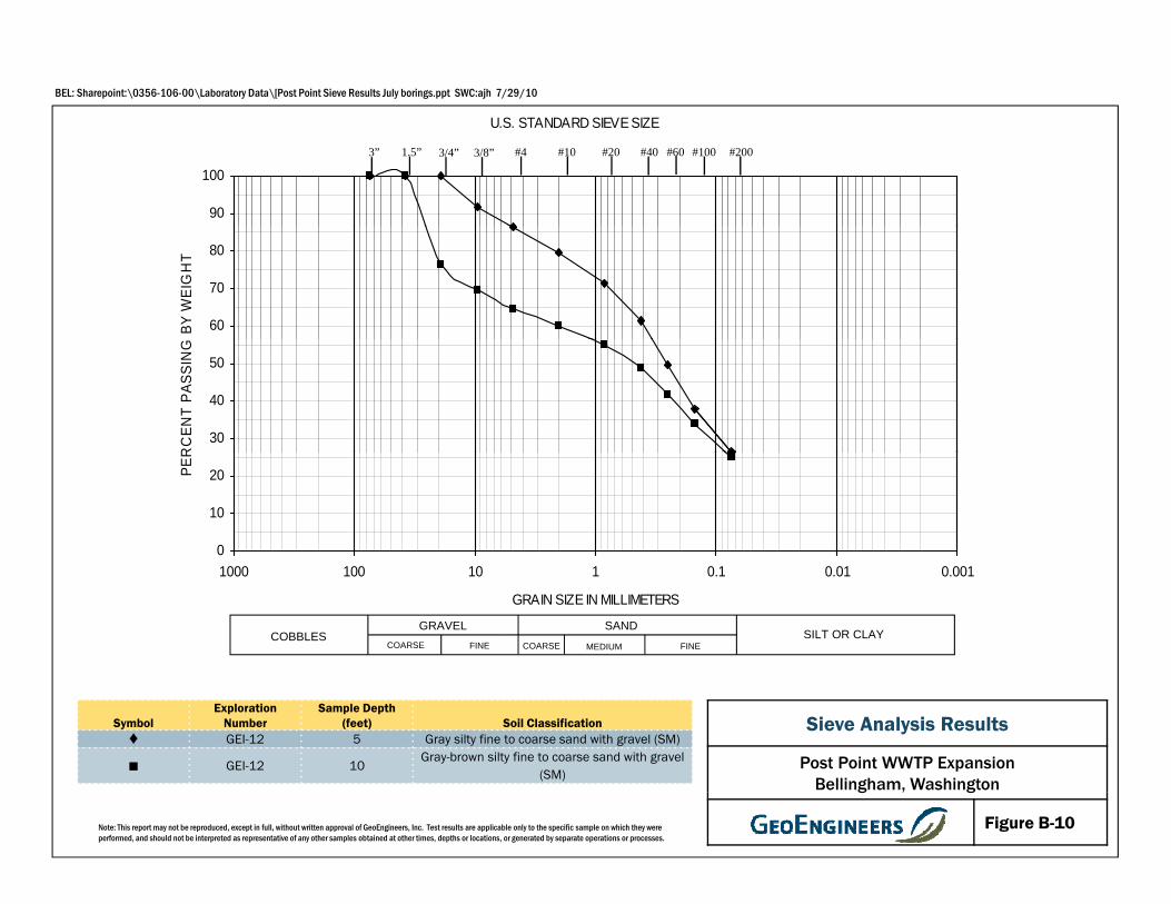
BEL: Sharepoint:\0356-106-00\Laboratory Data\[Post Point Sieve Results July borings.ppt SWC:ajh 7/29/10
U.S. STANDARD SIEVE SIZE
90
1003/8”3” 1.5” #4 #10 #20 #200#40 #60 #1003/4”
60
70
80
BY W
EIGHT
30
40
50
RCEN
T PAS
SING
0
10
20PER
SAND SILT OR CLAYCOBBLES GRAVELCOARSE MEDIUM FINECOARSE FINE
0.0010.010.11101001000GRAIN SIZE IN MILLIMETERS
Sieve Analysis Results
Post Point WWTP ExpansionBellingham, Washington
SymbolExploration
NumberSample Depth
(feet) Soil Classification♦ GEI-12 5 Gray silty fine to coarse sand with gravel (SM)
■ GEI-12 10Gray-brown silty fine to coarse sand with gravel
(SM)
Note: This report may not be reproduced, except in full, without written approval of GeoEngineers, Inc. Test results are applicable only to the specific sample on which they were performed, and should not be interpreted as representative of any other samples obtained at other times, depths or locations, or generated by separate operations or processes.
g , g
Figure B-10

BEL: Sharepoint:\0356-106-00\Laboratory Data\[Post Point Sieve Results July borings.ppt SWC:ajh 7/29/10
U.S. STANDARD SIEVE SIZE
90
1003/8”3” 1.5” #4 #10 #20 #200#40 #60 #1003/4”
60
70
80
BY W
EIGHT
30
40
50
RCEN
T PAS
SING
0
10
20PER
SAND SILT OR CLAYCOBBLES GRAVELCOARSE MEDIUM FINECOARSE FINE
0.0010.010.11101001000GRAIN SIZE IN MILLIMETERS
Sieve Analysis Results
Post Point WWTP ExpansionBellingham, Washington
SymbolExploration
NumberSample Depth
(feet) Soil Classification♦ GEI-13 5 Gray clayey sand with occasional gravel (SC)
■ GEI-13 25Gray-brown silty fine to coarse sand with
gravel (SM)Brown silty fine to medium sand with
Note: This report may not be reproduced, except in full, without written approval of GeoEngineers, Inc. Test results are applicable only to the specific sample on which they were performed, and should not be interpreted as representative of any other samples obtained at other times, depths or locations, or generated by separate operations or processes.
g , g
Figure B-11▲ GEI-14 5
Brown silty fine to medium sand with occasional gravel (SM)

BELL: P:\03\0356106\00\LAB\[Sieve].ppt AF2:ims 05/11/10
U.S. STANDARD SIEVE SIZE
90
1003/8”3” 1.5” #4 #10 #20 #200#40 #60 #1003/4”
60
70
80
BY W
EIGHT
.
30
40
50
CENT
PASS
ING
B
0
10
20PERC
SAND SILT OR CLAYCOBBLES GRAVELCOARSE MEDIUM FINECOARSE FINE
0.0010.010.11101001000GRAIN SIZE IN MILLIMETERS
Sieve Analysis Results
Post Point WWTP ExpansionBellingham, Washington
SymbolExploration
NumberSample Depth
(feet) Soil Classification
♦ TP-1 9Brown-gray silty fine to coarse sand with
gravel (SM)
Note: This report may not be reproduced, except in full, without written approval of GeoEngineers, Inc. Test results are applicable only to the specific sample on which they were performed, and should not be interpreted as representative of any other samples obtained at other times, depths or locations, or generated by separate operations or processes.
g , g
Figure B-12

BELL: P:\03\0356106\00\LAB\[Sieve].ppt AF2:ims 05/11/10
U.S. STANDARD SIEVE SIZE
90
1003/8”3” 1.5” #4 #10 #20 #200#40 #60 #1003/4”
60
70
80
BY W
EIGHT
.
30
40
50
CENT
PASS
ING
B
0
10
20PERC
SAND SILT OR CLAYCOBBLES GRAVELCOARSE MEDIUM FINECOARSE FINE
0.0010.010.11101001000GRAIN SIZE IN MILLIMETERS
Sieve Analysis Results
Post Point WWTP ExpansionBellingham, Washington
SymbolExploration
NumberSample Depth
(feet) Soil Classification♦ TP-2 4 Brown fine to coarse sand with gravel (SP)
Note: This report may not be reproduced, except in full, without written approval of GeoEngineers, Inc. Test results are applicable only to the specific sample on which they were performed, and should not be interpreted as representative of any other samples obtained at other times, depths or locations, or generated by separate operations or processes.
g , g
Figure B-13

BELL: P:\03\0356106\00\LAB\[Sieve].ppt AF2:ims 05/11/10
U.S. STANDARD SIEVE SIZE
90
1003/8”3” 1.5” #4 #10 #20 #200#40 #60 #1003/4”
60
70
80
BY W
EIGHT
.
30
40
50
CENT
PASS
ING
B
0
10
20PERC
SAND SILT OR CLAYCOBBLES GRAVELCOARSE MEDIUM FINECOARSE FINE
0.0010.010.11101001000GRAIN SIZE IN MILLIMETERS
Sieve Analysis Results
Post Point WWTP ExpansionBellingham, Washington
SymbolExploration
NumberSample Depth
(feet) Soil Classification
♦ TP-3 2 ½Brown fine to medium sand with silt and
occasional gravel (SP-SM)
■ TP-3 7½ Brown fine sandy silt (ML)
Note: This report may not be reproduced, except in full, without written approval of GeoEngineers, Inc. Test results are applicable only to the specific sample on which they were performed, and should not be interpreted as representative of any other samples obtained at other times, depths or locations, or generated by separate operations or processes.
g , g
Figure B-14

Note: This report may not be reproduced, except in full, without written approval of GeoEngineers, Inc. Test results are app licable only
to the specific sample on which they were performed, and should not be interpreted as representative of any other samples obt ained at
other times, depths or locations, or generated by separate operations or processes.
0
10
20
30
40
50
60
0 10 20 30 40 50 60 70 80 90 100
Pla
sti
cit
y In
de
x
Liquid Limit
PLASTICITY CHART
CL-ML ML or OL
CL or OL
OH and MH
CH or OH
Symbol
Exploration
Number
Sample Depth
(feet)
Moisture Content
(%)
Liquid Limit
(%)
Plasticity Index
(%) Soil Description
♦ GEI-1 30 33 40 17 Gray Clay (CL)
Atterberg Limits Test Results
Post Point WWTP Expansion
Bellingham, Washington
Figure B-15
10.1
10.2
BELL: P:\03\0356106\00\LAB\[Sieve].ppt AF2:ims 05/11/10
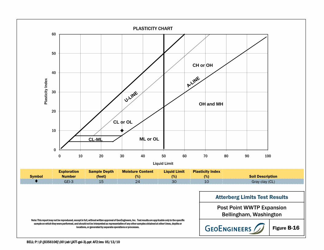
Note: This report may not be reproduced, except in full, without written approval of GeoEngineers, Inc. Test results are app licable only to the specific
sample on which they were performed, and should not be interpreted as representative of any other samples obtained at other t imes, depths or
locations, or generated by separate operations or processes.
BELL: P:\0\[0356106]\00\lab\[ATT-gei-3).ppt AF2:ims 05/13/10
0
10
20
30
40
50
60
0 10 20 30 40 50 60 70 80 90 100
Pla
sti
cit
y In
de
x
Liquid Limit
PLASTICITY CHART
CL-ML ML or OL
CL or OL
OH and MH
CH or OH
Symbol
Exploration
Number
Sample Depth
(feet)
Moisture Content
(%)
Liquid Limit
(%)
Plasticity Index
(%) Soil Description
♦ GEI-3 15 24 30 10 Gray clay (CL)
Atterberg Limits Test Results
Post Point WWTP Expansion
Bellingham, Washington
Figure B-16

Note: This report may not be reproduced, except in full, without written approval of GeoEngineers, Inc. Test results are app licable only to the specific
sample on which they were performed, and should not be interpreted as representative of any other samples obtained at other t imes, depths or
locations, or generated by separate operations or processes.
0
10
20
30
40
50
60
0 10 20 30 40 50 60 70 80 90 100
Pla
sti
cit
y In
de
x
Liquid Limit
PLASTICITY CHART
CL-ML
ML or OL
CL or OL
OH and MH
CH or OH
Symbol
Exploration
Number
Sample Depth
(feet)
Moisture Content
(%)
Liquid Limit
(%)
Plasticity Index
(%) Soil Description
♦ GEI-4 13.5 22 26 7 Gray silty clay (CL-ML)
Atterberg Limits Test Results
Post Point WWTP Expansion
Bellingham, Washington
Figure B-17
BELL: P:\03\0356106\00\LAB\[Atterberg].ppt AF2:ims 05/11/10

Note: This report may not be reproduced, except in full, without written approval of GeoEngineers, Inc. Test results are app licable only to
the specific sample on which they were performed, and should not be interpreted as representative of any other samples obtained at other
times, depths or locations, or generated by separate operations or processes.
BELL: P:\0\[0356106]\00\lab\[ATT-gei-7).ppt AF2:ims 05/13/10
0
10
20
30
40
50
60
0 10 20 30 40 50 60 70 80 90 100
Pla
sti
cit
y In
de
x
Liquid Limit
PLASTICITY CHART
CL-ML ML or OL
CL or OL
OH and MH
CH or OH
Symbol
Exploration
Number
Sample Depth
(feet)
Moisture Content
(%)
Liquid Limit
(%)
Plasticity Index
(%) Soil Description
♦ GEI-7 15 16 22 7 Gray silty clay (CL-ML)
Atterberg Limits Test Results
Post Point WWTP Expansion
Bellingham, Washington
Figure B-18

CERTIFICATE OF ANALYSIS
DATA RESULTS
CLIENT SAMPLE ID: 4/27/2010 GEI-2 S-5 15'ALS SAMPLE #: -01
CLIENT: Geoengineers, Inc.600 DuPont St.Bellingham, WA 98225
CLIENT CONTACT: Sean CoolCLIENT PROJECT ID: 0356-106-00
DATE: 6/8/2010ALS JOB#: 1005039
DATE RECEIVED: 5/12/2010WDOE ACCREDITATION #: C1336
ANALYTE RESULTS* UNITS**ANALYSIS
BYREPORTING
LIMITSDILUTION FACTOR
DETECTION LIMITS
pH by EPA-9045
pH PH UNITS7.2 SMRNA 10QC Batch prepared/extracted by EPA-9045 on 5/26/2010. Sample analyzed by EPA-9045 on 5/26/2010.
ANALYTE RESULTS* UNITS**ANALYSIS
BYREPORTING
LIMITSDILUTION FACTOR
DETECTION LIMITS
Anions by EPA-300.0M
Chloride MG/KG180 GAP10 100
Sulfate MG/KG340 GAP20 100QC Batch prepared/extracted by EPA-300.0M on 5/28/2010. Sample analyzed by EPA-300.0M on 5/28/2010.
ANALYTE RESULTS* UNITS**ANALYSIS
BYREPORTING
LIMITSDILUTION FACTOR
DETECTION LIMITS
Sulfide by EPA-376.1
Sulfide MG/LND ARI21.1 10QC Batch prepared/extracted by EPA-376.1 on 5/27/2010. Sample analyzed by EPA-376.1 on 5/27/2010.
ANALYTE RESULTS* UNITS**ANALYSIS
BYREPORTING
LIMITSDILUTION FACTOR
DETECTION LIMITS
Redox Potential by SM-2580
Redox Potential MV480 ARI20.10 10.1QC Batch prepared/extracted by SM2580 on 5/28/2010. Sample analyzed by SM2580 on 5/28/2010.
ANALYTE RESULTS* UNITS**ANALYSIS
BYREPORTING
LIMITSDILUTION FACTOR
DETECTION LIMITS
Soil Resistivity by ASTM G-57
Resistivity OHM-CM2500@ 21.5C
ARI2NA 12500@ 21.5C
0
QC Batch prepared/extracted by ASTM G-57 on 5/28/2010. Sample analyzed by ASTM G-57 on 5/28/2010.
* "ND" INDICATES ANALYTE ANALYZED FOR BUT NOT DETECTED AT LEVEL ABOVE REPORTING LIMT.
** UNITS FOR ALL NON-LIQUID SAMPLES ARE REPORTED ON A DRY WEIGHT BASIS.
APPROVED BY:
* Note: pH received and analyzed outside of hold time.
8620 Holly Drive Suite 100 Everett, WA 98208 425 356-2600 FAX 425 356-2626 Seattle 206 292-9059
Page 1

CERTIFICATE OF ANALYSIS
DATA RESULTS
CLIENT SAMPLE ID: 4/27/2010 GEI-4 S-3 7.5'ALS SAMPLE #: -03
CLIENT: Geoengineers, Inc.600 DuPont St.Bellingham, WA 98225
CLIENT CONTACT: Sean CoolCLIENT PROJECT ID: 0356-106-00
DATE: 6/8/2010ALS JOB#: 1005039
DATE RECEIVED: 5/12/2010WDOE ACCREDITATION #: C1336
ANALYTE RESULTS* UNITS**ANALYSIS
BYREPORTING
LIMITSDILUTION FACTOR
DETECTION LIMITS
pH by EPA-9045
pH PH UNITS8.3 SMRNA 10QC Batch prepared/extracted by EPA-9045 on 5/26/2010. Sample analyzed by EPA-9045 on 5/26/2010.
ANALYTE RESULTS* UNITS**ANALYSIS
BYREPORTING
LIMITSDILUTION FACTOR
DETECTION LIMITS
Anions by EPA-300.0M
Chloride MG/KG32 GAP10 100
Sulfate MG/KG410 GAP20 100QC Batch prepared/extracted by EPA-300.0M on 5/28/2010. Sample analyzed by EPA-300.0M on 5/28/2010.
ANALYTE RESULTS* UNITS**ANALYSIS
BYREPORTING
LIMITSDILUTION FACTOR
DETECTION LIMITS
Sulfide by EPA-376.1
Sulfide MG/LND ARI21.1 10QC Batch prepared/extracted by EPA-376.1 on 5/27/2010. Sample analyzed by EPA-376.1 on 5/27/2010.
ANALYTE RESULTS* UNITS**ANALYSIS
BYREPORTING
LIMITSDILUTION FACTOR
DETECTION LIMITS
Redox Potential by SM-2580
Redox Potential MV400 ARI20.10 10.1QC Batch prepared/extracted by SM2580 on 5/28/2010. Sample analyzed by SM2580 on 5/28/2010.
ANALYTE RESULTS* UNITS**ANALYSIS
BYREPORTING
LIMITSDILUTION FACTOR
DETECTION LIMITS
Soil Resistivity by ASTM G-57
Resistivity OHM-CM6500@ 22.0C
ARI2NA 16500@ 22.0C
0
QC Batch prepared/extracted by ASTM G-57 on 5/28/2010. Sample analyzed by ASTM G-57 on 5/28/2010.
* "ND" INDICATES ANALYTE ANALYZED FOR BUT NOT DETECTED AT LEVEL ABOVE REPORTING LIMT.
** UNITS FOR ALL NON-LIQUID SAMPLES ARE REPORTED ON A DRY WEIGHT BASIS.
APPROVED BY:
* Note: pH received and analyzed outside of hold time.
8620 Holly Drive Suite 100 Everett, WA 98208 425 356-2600 FAX 425 356-2626 Seattle 206 292-9059
Page 2

CERTIFICATE OF ANALYSIS
DATA RESULTS
CLIENT SAMPLE ID: 4/28/2010 GEI-6 S-4 10'ALS SAMPLE #: -05
CLIENT: Geoengineers, Inc.600 DuPont St.Bellingham, WA 98225
CLIENT CONTACT: Sean CoolCLIENT PROJECT ID: 0356-106-00
DATE: 6/8/2010ALS JOB#: 1005039
DATE RECEIVED: 5/12/2010WDOE ACCREDITATION #: C1336
ANALYTE RESULTS* UNITS**ANALYSIS
BYREPORTING
LIMITSDILUTION FACTOR
DETECTION LIMITS
pH by EPA-9045
pH PH UNITS7.5 SMRNA 10QC Batch prepared/extracted by EPA-9045 on 5/26/2010. Sample analyzed by EPA-9045 on 5/26/2010.
ANALYTE RESULTS* UNITS**ANALYSIS
BYREPORTING
LIMITSDILUTION FACTOR
DETECTION LIMITS
Anions by EPA-300.0M
Chloride MG/KG23 GAP10 100
Sulfate MG/KG190 GAP20 100QC Batch prepared/extracted by EPA-300.0M on 5/28/2010. Sample analyzed by EPA-300.0M on 5/28/2010.
ANALYTE RESULTS* UNITS**ANALYSIS
BYREPORTING
LIMITSDILUTION FACTOR
DETECTION LIMITS
Sulfide by EPA-376.1
Sulfide MG/LND ARI21.2 10QC Batch prepared/extracted by EPA-376.1 on 5/27/2010. Sample analyzed by EPA-376.1 on 5/27/2010.
ANALYTE RESULTS* UNITS**ANALYSIS
BYREPORTING
LIMITSDILUTION FACTOR
DETECTION LIMITS
Redox Potential by SM-2580
Redox Potential MV380 ARI20.10 10.1QC Batch prepared/extracted by SM2580 on 5/28/2010. Sample analyzed by SM2580 on 5/28/2010.
ANALYTE RESULTS* UNITS**ANALYSIS
BYREPORTING
LIMITSDILUTION FACTOR
DETECTION LIMITS
Soil Resistivity by ASTM G-57
Resistivity OHM-CM4350@ 21.5C
ARI2NA 14350@ 21.5C
0
QC Batch prepared/extracted by ASTM G-57 on 5/28/2010. Sample analyzed by ASTM G-57 on 5/28/2010.
* "ND" INDICATES ANALYTE ANALYZED FOR BUT NOT DETECTED AT LEVEL ABOVE REPORTING LIMT.
** UNITS FOR ALL NON-LIQUID SAMPLES ARE REPORTED ON A DRY WEIGHT BASIS.
APPROVED BY:
* Note: pH received and analyzed outside of hold time.
8620 Holly Drive Suite 100 Everett, WA 98208 425 356-2600 FAX 425 356-2626 Seattle 206 292-9059
Page 3
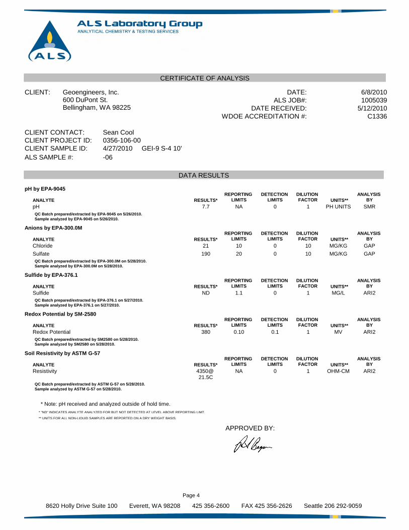
CERTIFICATE OF ANALYSIS
DATA RESULTS
CLIENT SAMPLE ID: 4/27/2010 GEI-9 S-4 10'ALS SAMPLE #: -06
CLIENT: Geoengineers, Inc.600 DuPont St.Bellingham, WA 98225
CLIENT CONTACT: Sean CoolCLIENT PROJECT ID: 0356-106-00
DATE: 6/8/2010ALS JOB#: 1005039
DATE RECEIVED: 5/12/2010WDOE ACCREDITATION #: C1336
ANALYTE RESULTS* UNITS**ANALYSIS
BYREPORTING
LIMITSDILUTION FACTOR
DETECTION LIMITS
pH by EPA-9045
pH PH UNITS7.7 SMRNA 10QC Batch prepared/extracted by EPA-9045 on 5/26/2010. Sample analyzed by EPA-9045 on 5/26/2010.
ANALYTE RESULTS* UNITS**ANALYSIS
BYREPORTING
LIMITSDILUTION FACTOR
DETECTION LIMITS
Anions by EPA-300.0M
Chloride MG/KG21 GAP10 100
Sulfate MG/KG190 GAP20 100QC Batch prepared/extracted by EPA-300.0M on 5/28/2010. Sample analyzed by EPA-300.0M on 5/28/2010.
ANALYTE RESULTS* UNITS**ANALYSIS
BYREPORTING
LIMITSDILUTION FACTOR
DETECTION LIMITS
Sulfide by EPA-376.1
Sulfide MG/LND ARI21.1 10QC Batch prepared/extracted by EPA-376.1 on 5/27/2010. Sample analyzed by EPA-376.1 on 5/27/2010.
ANALYTE RESULTS* UNITS**ANALYSIS
BYREPORTING
LIMITSDILUTION FACTOR
DETECTION LIMITS
Redox Potential by SM-2580
Redox Potential MV380 ARI20.10 10.1QC Batch prepared/extracted by SM2580 on 5/28/2010. Sample analyzed by SM2580 on 5/28/2010.
ANALYTE RESULTS* UNITS**ANALYSIS
BYREPORTING
LIMITSDILUTION FACTOR
DETECTION LIMITS
Soil Resistivity by ASTM G-57
Resistivity OHM-CM4350@ 21.5C
ARI2NA 14350@ 21.5C
0
QC Batch prepared/extracted by ASTM G-57 on 5/28/2010. Sample analyzed by ASTM G-57 on 5/28/2010.
* "ND" INDICATES ANALYTE ANALYZED FOR BUT NOT DETECTED AT LEVEL ABOVE REPORTING LIMT.
** UNITS FOR ALL NON-LIQUID SAMPLES ARE REPORTED ON A DRY WEIGHT BASIS.
APPROVED BY:
* Note: pH received and analyzed outside of hold time.
8620 Holly Drive Suite 100 Everett, WA 98208 425 356-2600 FAX 425 356-2626 Seattle 206 292-9059
Page 4

CERTIFICATE OF ANALYSIS
QUALITY CONTROL RESULTS
METHODMATRIXQC SAMPLE ID ANALYTE
BLANK RESULTS
RESULT UNITS
CLIENT: Geoengineers, Inc.600 DuPont St.Bellingham, WA 98225
CLIENT CONTACT: Sean CoolCLIENT PROJECT ID: 0356-106-00
DATE: 6/8/2010ALS JOB#: 1005039
DATE RECEIVED: 5/12/2010WDOE ACCREDITATION #: C1336
EPA-300.0MSoilMBLK-5282010 Chloride MG/KGND(<1.0)
EPA-300.0MSoilMBLK-5282010 Sulfate MG/KGND(<2.0)
EPA-376.1WaterMBLK-5272010 Sulfide MG/LND(<0.050)
APPROVED BY:
8620 Holly Drive Suite 100 Everett, WA 98208 425 356-2600 FAX 425 356-2626 Seattle 206 292-9059
Page 5

CERTIFICATE OF ANALYSIS
QUALITY CONTROL RESULTS
METHODMATRIXQC BATCH ID ANALYTE
BLANK SPIKE/BLANK SPIKE DUPLICATE RESULTS
BLANK SPIKE RECOVERY
BLANK SPIKE DUPLICATE RECOVERY
RPDSPIKE AMOUNT
CLIENT: Geoengineers, Inc.600 DuPont St.Bellingham, WA 98225
CLIENT CONTACT: Sean CoolCLIENT PROJECT ID: 0356-106-00
DATE: 6/8/2010ALS JOB#: 1005039
DATE RECEIVED: 5/12/2010WDOE ACCREDITATION #: C1336
EPA-300.0MSoilR69086 Chloride 101% 101% 0100
EPA-300.0MSoilR69086 Sulfate 109% 106% 3100
SM2580SoilR69188 Redox Potential 100%100 NA NA
APPROVED BY:
8620 Holly Drive Suite 100 Everett, WA 98208 425 356-2600 FAX 425 356-2626 Seattle 206 292-9059
Page 6

APPENDIX C Previous Site Explorations
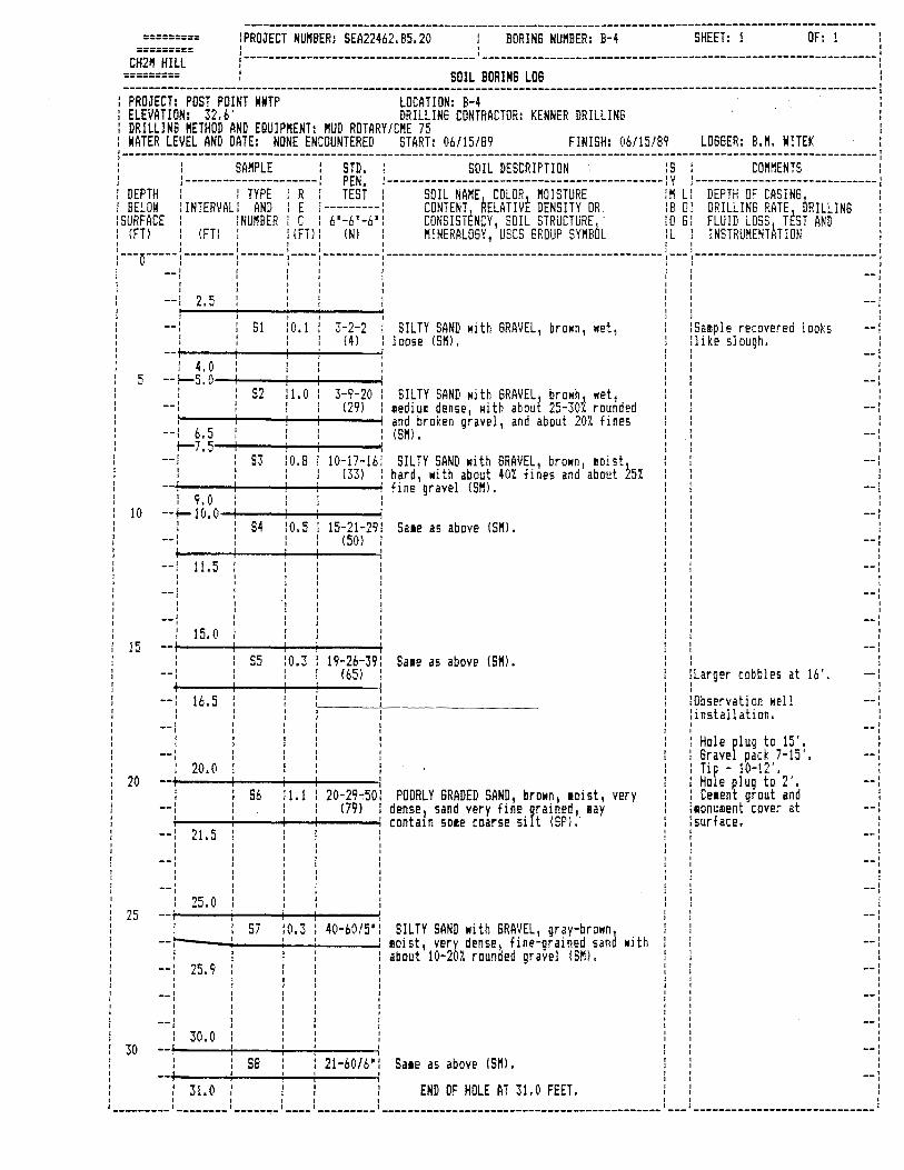
========= lPROJECT NUl'IBER: SEA22462.B5.20 BORING NU"BER: B-4 SHEET: 1 OF: 1 I I
========= I I I I I I ,------------------------------------- ---------------------------------------------------------------! CH21' HILL I I
: SOIL BORING LOG : ------------------------------------------------------------------------------------------------------------------------------------------: : PROJECT: POST POINT WWTP LOCATION: B-4
ELEVATION: 32.6' DRILLING CONTRACTOR: KENNER DRILLING DRILLIN6 "ETHOD AND EQUIP"ENT: "LID ROTARY/C"E 75 WATER LEVEL AND DATE: NONE ENCOUNTERED START: 06/15/89 FINISH: 06/15/89 LOSSER: B.1'. WITEK
:------------------------------------------------------------------------------------------------------------------------: : SA"PLE : STD. : SOIL DESCRIPTION : S : C01'MENTS : :---------------------: PEN. 1--------------------------------------------lY :-----------------------------:
DEPTH : : TYPE : R TEST : SOIL NAME COLOR MJSTURE :M L: DEPTH OF CASING BELOW :INTERVAL: AND : E :---------: CONTENT RELATIVt DENSITY OR. :Bo: DRILLING RATE! 0RILLIN6
:SURFACE : lNUMBER : C : 6•-6•-6 1: CONSISTENCY, SOIL STRUCTURE . :o s: FLUID LOSS 1 TtST AND
: IFTl : IFTI : IFTI: IN) 1'!NERALOBY, uses BRDUP SYMBbL :L INSTRUMENTATION I I I I I 1 I r I I I I l I I t I :---0-----:--------:-------:----:---------:--------------------------------------------:---:-----------------------------: I __ 1 I I I I I I I I I I I l I I I t
--: I
--: I I
2.5
4.0
I I I I I I I I
: l : --: I
Sl :0.1 3-2-2 (4)
SILTY SAND with GRAVEL, brown, wet, 1 oose ISMI.
I I I I I I
:sample recovered looks :like slough.
I I I I
5 --!-5. 0-;-----+--+---~ --: --:
I
: 6.5
S2 : 1. 0 3-9-20 129)
t-7. 5-t-----+--+----'I,
SILTY SAND with BRAVEL, brown wet, medium dense, with about 25-30i rounded and broken gravel, and about 207. fines ISMI.
--: S3 :o.B 10-i7-16: SILTY SAND with GRAVEL, brown, moist : 1331 hard, with about 40l fines and about 257.
9.0 fine gravel ISMI.
1 (l --1-10. 0--t----+---+----
15
20
25
30
: S4 :o.5 15-21-29: Sa1e as above !SMJ. --: 1501
I
I
' --: I I
--: --:
I I
--: I I
--: I I
I I
--: --:
I I
--:
--: I I
--: I I
--: I I
11. 5
15.0
16.5
20.0
21. 5
25.0
25.9
30.0
31.0
S5
56
S7
SB
I
' I
·'
:o.3
: 1.1
:o.3
19-26-39: !65)
20-29-:50: 179)
Sa1e as above IS1'1.
POORLY 6RADED SAND, brown, 1oist, very dense 1 sand very fine grained, 1ay contain so1e coarse silt ISPI.·
40-60/5 1: SILTY SAND with GRAVEL, gray-brown~ ' moist, verb dense, fine-grained san with : about 10-2 I. rounded gravel ISl'D. I I I I I I
21-60/6 1:
END OF HOLE AT 31.0 FEET.
I I I I I I
:Larger cobbles at 16'. I I
:Observation well :installation.
Hole plug to 15'. 6ravel pack 7-15'.
: Ti - 10-12'. : Ho~e plug to 2·. : Ce1ent grout and :1onu1ent cover at :surface.
I I
--: I I
--: I I
--: I I
--:
--: I I
I I
--! I I
--: --:
I I
--: I I
--: I I
--: I I
--:
--: I I
--: I I
--: I I
--: I I
--: 1 I
--! I I
I I I I 1 --------- -------- ------- ____ 1 _________ 1 ____________________________________________ , ___ • _____________________________ 1

-----------~--~--~------------~------~----------------------~--~------------------~--~------========= lPROJECT NUMBER: SEA22462.B5.20 BORING NUMBER: B-6 SHEET: l OF: 3 ' ' ' :-------------------------------------!-----~--------------------------------------------------------' '
========= CH2M HILL
========= : SOIL BORING LOS ------------------------------------------------------------------------------------------------------------------------: PROJECT: POST POINT WWTP LOCATION: B-6
l ELEVATION: 23.6' DRILLING CONTRACTOR: KENNER DRILLING : DRILLING "ETHOD. AND EQUIPMENT: MUD ROTARY/CME 75 : WATER LEVEL AND DATE: 5.8' 07/21/89 START: 06/22/89 FINISH: 06/23/89 LD6GER: B.M. WITEK 1------------------------------------------------------------------------------------------------------------------------l l l SAMPLE STD. i SOIL DESCRIPTION JS l COMMENTS : l :---------------------[ PEN. r--------------------------------------------:Y !-----------------------------! l DEPTH : : TYPE l R : TEST : SOIL NAME COLOR MOISTURE : M L: DEPTH OF CASI NS : BELOW ilNTERVALl AND l E :---------: CONTENTi RELATIVE DENSITY OR :Bo: DRILLING RATEi 0RILLIN6 JSURFACE lNUMBER i C i 6'-6'-6'1 CONSISTtNCY, SOIL STRUCTURE1. 10 Gi FLUID LOSS 1 TtST AND 'l l IFTl IFTI : IFTl l (NI MINERALOGY I uses GROUP SYMBuL :L INSTRUMENTATION : I l I I I l I ! I I I I i l l :---u-----:--------i-------:----:---------i--------------------------------------------:---:srarr-or-arrrring-:-3:15-----: : --l : 1 : l J lP.M. --l ' ' ' ; l I
--l ' ' ' ' ' ' --l :cuttings - loose gravel 1 ' : sand and si 1 t. ' --: --: 5.0 ' ' 5 ' ' 51 lO.O 4-4-4 No recovery. ' ' (8) --[
' ' --l 6.5 --: ' ' --: --[
' ' ' ' --l --: ' 10.0 ' ' ' 10 --:
82 : 1. 8 1-2-2 SANDY SILT to a SANDY LEAN CLAY, bro•n, ' ' --t 14) wetd soft, with occasional iravel and --: san sea1s, ooderatel y pl as i c !HL to --: 11.5 CLJ • .
--l ' ' --[
15.0 15 --:
' 5T3 :1.8 Botto• of tube: SANDY LEAN CLAY. ' ' ' --! ' ' ' ' ' ' --+- 17.0 --l 54 l 1. 8 3-3-3 SANDY LEAN CLAY, grar, wet, soft to ' ' --: 16) 1ediu1 f ir1, moderate y plastic ICLJ,
--l 18.5 --l ' 20.0 ' ' ' 20 --: ' S5 :o.7 6-3-3 Saoe as above !CLJ, with interbeds of ' ' ' --: ' (6) POORLY GRADED SILTY SANDP aray, Met, --l ' loose, 1ediu1 grained IS - Ml. ' ' --: 21. 5 --1 ' ' ' ' --l ' ' ' ' ' ' --l --:
25.0 25 --l
56 : 1. 5 4-6-5 Sa1e as above, ICLI except Mith ' ' --: I 11 J occasional gravel and no sand seams, --1 t--26.5
--: ' ' --: ' ' ' ' ' ' ' ' --: :Harder at 29 '. --: ' ' 30 --: --:
' ' ' ' ' ' --: ' --: ' ' ' ' ' ' ' ' ' ' ' ------- ----- ------ ____ 1 _________ 1 ___________________________________________ -- ----------------------------

-------------~---~----~----------~--------~--------------------------------------~-------------========= =========
:PROJECT NUMBER: SEA22462.B5.20 BORING NUMBER: B-6 SHEET: 2 OF: 3 ' ' ' ' ' CH2M HILL :-------------------------------------1-------------------------------------~------------------------:
' ' ========= : SOIL BORING LOG ----~--~----------------------~--------------------------------------------------------------------------------------: : PROJECT: POST POINT WWTP LOCATION: B-6 '
l ELEVATION: 23.6' DRILLING CONTRACTOR: KENNER DRILLING l DRILLING METHOD AND EQUIPMENT: MUD ROTARY/CHE 75 : WATER LEVEL AND DATE: 5.s· 07/21/89 START: 06/22/89 FINISH: 06/23/89 LOGGER: B.M. WITEK :------------------------------------------------------------------------------------------------------------------------: : : SAMPLE : STD. : SOIL DESCRIPTION :s : COMMENTS : l l---------------------: PEN. 1--------------------------------------------lY :-----------------------------: : DEPTH : TYPE : R ' TEST : SOIL NAHE COLOR MOISTURE lH L: DEPTH OF CASING : BELOW :INTERVAL: AND : E ---------: CONTENT! RELATIVE DENSITY OR :Bo: DRILLING RATEl DRILLING :SURFACE :NUMBER : C 6'-6'-6': CDNSISTtNCY 1 SOIL SiRUCTURE
0· :o s: FLUID LOSS 1 TtST AND
: (FT) IFTI : (FTJ INI : HINERALOSY, uses GROUP SYMB L :L INSTRUMENTHTION I I ! l I I :--3u-----: l ;-------------------------------------------- :---1-----------------------------1
35
40
45
50
55
60
--: S7 : 1. 5 i3-50- INTERBEDDED, SILTY SAND and SILTY POORLY : : t- 60/5' GRADED SAND, both gray, wet, very dense,
31.4 silty sand 1s fine grained with occasional gravel, poorly graded sand is oedium to coarse grained ISM to SM-SPl. ' ' ' ' --1
' '
' ' --i
35.0
SB :o.s 11-9-9 I 1 Bl
,1--~~--1~~~+-~-+-~~~..;
--] 36.5
' ' --:
' ' --: ' --: ' '
--l '
40.0
41. 5
45.0
--l 46.5 ' ' --!
--]
' '
--:
50.0
--: 51.5 ' ' --: ' ' --1
55.0
S9 :LO
SlO :o.o
13-21-17: 138)
9-12-17 129)
Sll : 1.0 9-13-18 (31)
: s12 :o.a 14-44---:---::':"'"::--~~~-i-~-i-~6~c~11j4~·~
56.3
' ' --: ' ' --r
--:
FAT CLAY to SANDY LEAN CLAY with GRAVEL, gray, wet, very stiff ICH to CU.
SANDY LEAN CLAY interbedded with SILT, both gray, clay is wet, silt is moist hard, with occasional gravel ICL to Mll.
SANDY LEAN CLAY gray, wet with occasional gravel, very still ICLI,
SANDY SILT to SANDY LEAN CLAY, gray, wet, hard, with occasional gravel IHL to cu.
SANDY SILT, sa1e as above IMLJ.
' ' ' ' :Froo 45' down, dr1ll1ng tin and out of gravel 11 ayers. ' '
' ' --! ' ' --[ ' '
--:
--: ' ' --: ' ' --: ' ' --:
--: --: --: --~
' ' --: --l
' ' --: ' ' --: ' ' --:
--: ' ' --: ' ' --: ' ' ' ' --:
--:
--: ' ' ' ~~~--- ------~ ------- -~- ~----~- ------------~----------------~------------ --- -~----------------~--------!

' '
======== :PROJECT NUMBER: SEA22462.B5.20 BORJNS NUMBER: B-6 SHEET: 3 OF: 3 : ' ' ' ' ' ' ,------------------------------------- ---------------------------------------------------------------, ' '
======== CH2M HILL
========= : SOIL BORIN6 LOS : ----------~----------------------------~------------------------------------------------------------------------------1
: PROJECT: POST POINT WWTP LOCATION: B-6 : : ELEVATION: 23.6' DRILLING CONTRACTOR: KENNER DRILLING : : DRILLING HETHOD AND EQUIPMENT: MUD ROTARY/CME 75 : : WATER LEVEL ANO DATE: 5.8' 07/21/89 START: 06/22/89 FINISH: 06/23/89 LOSSER: B.M. WITEK : 1------------------------------------------------------------------------------------------------------------------------l : : SAHPLE : STD. : SOIL DESCRIPTION :s : COMMENTS :
[---------------------: PEN. :--------------------------------------------1Y 1-----------------------------l DEPTH BELO~
:SURFACE : IFTI
: : TYPE : R i TEST : SOIL NME COLOR ~OISTURE :H L: DEPTH OF CASING :INTERVAL: AND : E :---------: CONTENT! RELATIVE DENSITY OR. :BO: DRILLING RATE, ORILLINS
: NUHBER : C : 6 '-6 "-6": CONSISTtNCY, SOI l STRUCTURE i - : 0 6: FLUID LOSS 1 TEST AND !FTJ : (FTJ: INJ MINERALOSY, uses SROUP SYMBuL :L : INSTRUMENTATION
I I I I I
' i::' :----;.----;.---;.---~. ' ' ' :--bri-----! , , :--------------------------------------------:---inoservation-werr-------------: 60. 2...__..,[,_'-S'-13'-_,:.:.o.:.J.:._;-__:;_6f:..J/-'2'-'~ No recovery. : i nstal 1 at ion,
'
--r
65.0 65
:--__ s14 :o.3 60/4.5' [ 65.4-..;.....,:;,;;_;,._.;.;.:..:_;._;;,,;.:..;,:,:_--;
' ' --l ' ' --:
70 --l ' ' --1 ' ' ' ' ' ' --l ' ' --l
75 --: ' ' --l ' ' --l ' ' --: ' ' --: ' ' 80 --l ' ' --l ' ' --: ' ' --1
--r ' ' 85 --l
' ' --: ' ' --: ' ' --: ' ' 90 --:
' .. ' ' ' '
' ' ' ' ' '
SILTY SANO •ith GRAVEL, grax •ith bro•n pods 1 wet, very dense, with ~5X gravel !SHI.
ENO OF HOLE AT 65' 4.5'.
' ' :Drilled hole 7' north of :ori1inal location to 17' :dep h. ' ' Gravel pack fro• 11-17', : Tip fro! 13-15'. : Ce•ent grout to surface :with protective 1onu1ent leasing. ' '
' ' --l ' ' --: ' ' --:
' ' --1 ' ' --: ' '
--t ' ' -: ' ' --:
--l
--1
--: ' ' --: ' ' --: ' ' --! ' ' --1
--:
' ' -- :
' ' --: l --l --l ' ' ' ' I I I I I I I I I
l--~-----l--------'-~----J----'---------J--------------------------------------------1---1---------~------------------!

------------------------------------------------------------------------~--------------------------====== lPROJECT NIJllBER: SEA22462.B5.20 BORIN6 NUllBER: B-7 SHEET: 1 OF: 2 ======= }------~-----------------------~---- ---------------------------------------------------------------CH2" HILL ' ===== l SOIL BORING LOS
: PROJECT: POST POINT NNTP LOCATION: B-7 : ELEVATION: 22.4' DRILLJNS CONTRACTOR: KENNER DRILLIN6 : DRILLINS llETHOD AND EQUIP"ENT: "UD ROTARY/C"E 75 : NATER LEVEL AND DATE: 5.8' 07/21/89 START: Ob/20/89 FINISH: Ob/21/89 LOSSER: B.". WITEK , l--------------------------------------------------------------------------~---------------------------------------------1 : SA"PLE STD. : SOIL DESCRIPTION : s : co""ENTS : l 1---------------------l PEN. 1--------------------------------------------:Y :-----------------------------: : DEPTH : : TYPE : R : TEST : SOIL NA"E COLOR "OJSTURE :" Li DEPTH OF CASING. : BELOW I INTERVAL I AND : E :---------: CONTENTl kELATIVE DENSITY OR: IB o: DRILLING RATEl ORILLING :SURFACE : lNU"BER : C : b'-b'-b'l CONSISTtNCY, SOIL STRUCTURE 1 10 61 FLUID LOSS 1 TtST AND : (FT) : (FTJ : : (FT): (N) : "INERALOSY' uses GROUP SYMBUL IL : INSTRU"ENTRT!ON I ! I I I I t I f
;---u-----:--------1-------1----1
---------i--------~------~--------------------------:---;-----------------------------: I --1 I I I I --: 1 f I I I l I I I I I I I t
5
JO
15
20
25
--l I I l I --1 I I I I l I I I I I I I
--: l : --l ' ' ' ' ' ' --l --l I 5.0 I
: Sl 10.7 : 7-8-b l SILTY SRAVEL •ith SAND bro•n •et, --: (!4) : 1ediu1 dense, •ith abou/ 10-151 fines
t----i---+--t-----;' (S"). --1 b.5
' ' --: ' ' --: : 10.0
--: S2 11.0 : 5-10-lb : Upper b': SILT •ith SAND and occasional
: : !26) : SRAYEL, gray, •et, stiff ("L), t----<r---+--t------1
--: ' ' --: ' ' --: ' ' ' ' --l
--1 ' ' --: ' ' --! ' ' ' ' ..... J
t
11.5
15.0
lb.5
20.0
S3
: ST4 : 1
: 1. 8 :
:2.0 : l {
: Lo•er b': SILTY, NELL GRADED SAND, gray : •et, 1ediu1 dense, •ith occasional gravel l (SM-SNI. :
2-1-2 l LEAN CLAY •ith SANDI gray/ •et, soft, (3) : •ith occasional shel s !CL •
LEAN CLAY, gray, wet, soft !CL),
-+- 22.ll-+----+-+----l :
--: --: 23.5
: 25.0
' ' --:
SS
Sb
l0.3 I
12.0 : ' '
2-2-2 (4)
1-3-3 (bl
BROKEN GRAVEL in a SILT "ATRIX.
Sa1e as in 53 above, except 1ediu1 fir• !CU.
:- 2b.5 -+----11---+----: --!
' ' --: ' ' --l l l.
' ' ' ' ' ' : : :Sa1ple appears to be I slough. ' ' ' ' ' ' : : ' ' ' ' ' '
--: ' ' --: ' ' --1 ' ' --: ' ' -: ' ' --: ' ' --1 '
--, ' ' --1 ' ' --1
--: ' ' --1 ' ' --: ' ' .. -l ' ' .. -: ' ' -: ' ' --1
-: ' ' --: ' ' -: ' ' -: ' ' --1 ' ' --: !
30 --: : l : :
-I I -l ' ' ' ' ' ' ' ' ' ----0 --- -----· -- ------- -----------------------------I --- .. ------... ---------------1

-----------------------------------------~--------------~--------~--~----~--------~------------======= :PROJECT NIJl!BER: SEA22462.B5.20 BORING NU"BER: B-7 SHEET: 2 OF: 2 : ========= : : : CH2" HILL :-~------~~~----~----~---------- -------------------~--------~----~----~~----~------------:
======== : SOIL BllfiINS LOS l ----------------------------------------------------------~------------------~-----------------~----------------------:
l PROJECT: POST POINT WWTP LOCATION B-7 : ELEVATION: 22.4' DRILLING CONTRACTOR: KENNER DRILLING : DRILLING "ETHOD AND EQUIP"ENT: "UD ROTARY/C"E 75 : WATER LEVEL AND DATE: 5,8' 07/21/89 START: 06/20/89 FINISH: 06/21/89 LOSSER: B.". WITEK 1----------------------------------------------------------------------------------------------~------------------------1 : : SA~LE : STD. : SOIL DESCRIPTION . :s : co""ENTS : : :---------------------: PEN. 1--------------------------------------------IY :-----------------------------! : DEPTH : : TYPE : R : TEST : SOIL NAME COLOR "OISTURE :M L: DEPTH OF CASING : : BELOW I INTERVAL: AND : E :---------: CONTENTJ RELATIVE DENSITY OR: 18 Oi DRILLING RATEJ DRILLING :SURFACE : :NUMBER : C : b'-6'-6': CONSISTtNCY, SOIL STRUCTUREb :o 61 FLUID LOSS 1 T~ST AND : (FT) : (FTJ : : IFTl: IN) : MINERALOGY' uses GROUP SYMB l : L : INSTRU"ENTATION I I l I I I I I 1 I l I 1
:--3~-----r----i . l :-------------------------------------------- :--- :Bottoi·o1-1une·oent·sy-------: --1 ST7 12.0 I : Botto• of tube looks like: SILT with : :gravel. --:
35
40
45
so
55
: : SAND and GRAVEL, gray, wet, 1ediu1 firt : : : --1-32.0 to stiff l"U. : :scrape fro• rock along --:
: SB :2.0 : 5-6-7 : SILT, gray, wet, 1oderately plastic, : l3/4 of tube. : : (13) : stiff !MU. : --:
1--~~1--~-+~+-~~--1' I : --: 33.5
: 35.0
' ' --: --: 36.5
' ' --: ' ' --: ' ' ' ' --:
40.0
--: 41.5 ' ' --1 • ' --l l 45.0
' ' --:
--: 46.S ' ' --: ' ' --1
50.0
l"S0.4 ' ' --: ""-..,,! ' ' ' ' --: ' ' ' ' ' ' --l ' ' ' ' ' ' --l ' 55.0 '
S9 10.5 : ' '
5-6-7 (13)
SILT! sa1e as above, possibly a lean clay "L-CL?l.
S!O :2.0 : 2-4-6 LEAN to FAT CLAY, gray, wet, stiff, with (10) fine to 1ediu1 sand partings ICL to CH).
Sit : 1.0 I 10-18-301 SILT with SAND and OCCASIONAL GRAVEL, (48) : gray, wet, very dense !Ml),
'
Sl2 10.1 60/5' : SILTY SAND with GRAVEL, gray, wet, very (31) : dense !SM>.
' ' ' ' ' ' ' ' ' ' ' ' ' ' ' ' ' '
• ' :Drilling got harder at :43' - 1ore sand and I gravel. ' ' ' ' ' ' ' ' ' '
--t ' • --: ' ' --: ' ' --: ' ' --l
--:
--: ' ' --: ' ' --: ' ' --1 ' • --: • ' --:
--l ' ' : Hit real hard oateri al at -- :
147.5' I
' ' ' ' ' ' ' ' ' ' ' ' ' ' ' ' :Sot sandier at 52' - a :little easier to drill.
• ' --: ' • --: ' ' --: ' ' -: ' ' --i ' ' I --!
' ' ' ' I --1 ' ' ' ' :Observation well --:
: S!3 :o.3 : 22-b0/6'1 SANDY SILT, gray! wet 1 very hard, with :installation. : --:-. 56.0 ' ' ' about S-10% grave IMLI. : --:
I : : I I Drilled hole 7,5' north : --: I I lof original location to --:
: : : END OF HOLE AT 56.5 FEET. :17' derth. : --: I : l Grave pack fro1 11-17'. --:
: : : l Tip fro1 13-15'. l --1 : t I Ce1ent grout to surface --!
l I h1ith protective 1onu1ent l 60 --: I leasing. --:
I I I I I I I I
--: l : --: I I I I I I
I I I I I I I I I t I I I I I I I I , _________ • ________ , _______ 1 ____ • _________ 1 ____________________________________________ , ___ • _________________________ ~ __ 1

========= /PROJECT NUMBER: SEA22462.B5.20 BORING NUMBER: B-8 SHEET: 1 OF: 4 I ========= ' ' '
CH2M HILL :-------------------------------------!---------------------------------------------------------------: ' ' ========= I SOIL BORING LOB
------------------------------------------------------------------------------------------------------------------------: PROJECT: POST POINT NWTP LOCATION: B-8 ELEVATION: 19.2' DRILLING CONTRACTOR: KENNER DRILLING DRILLIN6 METHOD AND EQUIPMENT: KUD ROTARY/CME 75
I WATER LEVEL AND DATE: NOT RECORDED START: 06115189 FINISH: 06/17/89 LOGGER: B.N. WITEK l----------------------------------------------------------------------------------------------------------------------· : : SA~PLE I STD. : SO IL DESCRIPT !ON : S COMMENTS i l :---------------------] PEN. :--------------------------------------------:Y :-----------------------------:
DEPTH : : TYPE : R : TEST : SD IL NAME l COLOR t MO! STURE : .~ Li DEPTH OF CAS ms' : BELOW INTERVALl AND l E l---------: CONTE~iT; hELAT!V ... DE~~SITY. DR :B D\ DRILLING F~ATEl DR1LL!NS lSURFACE :NUMBER : C I 6~-b·-t.~: CONSISTttlCY 1 SOI!. .. SiRUCTURE, -- :o Gi FLU1D LDSSi TtST AND l (fj) \FT} : (FT) l (N) /'llNERALOGY I uses 8RDUP SYMBOL ;L INSTRUMENT HT ION ' ' ' I I I I I I . I :---u-----:--------:-------:----:---------:--------------------------------------------1---:-----------------------------:
20
25
30
-- I l i ! I ! ! I ! I I ! l
' ' ' '
20.0
--: --l 2l.5
--1 ' '
25.0
' ' --l +--26.5
--1
2B.5
--: ' ' ' 30.0 ' --:
54 : 1.2
S5 :2.0
5T6
SB
' '
' :2.0 ' '
3-6-9 (15)
0-2-1 (3j
2-2-3 ("' ,,
Sa•e as above, e•ceot gray in lower B' of sampler and brown· above, with thin 0/16' or less) zones of sand (Cli.
LEAN CLAY, gray, wet, soft, with uo to 5/. 1ediu• sand and occasional shells and fine gravel (Cli.
Same as S5 1 gray, wet, 1edium fir~ (CU.
' --l
--:
--: ' ' --:
========= /PROJECT NUMBER: SEA22462.B5.20 BORIN6 NUMBER: B-B SHEET: 2 OF: 4 ========= ' ' ' ' ' ' CH2" HILL !------------------------------------- ---------------------------------------------------------------! ' ' ~======= i SOIL BOR!NS LOS i
------------------------~------------------------------------------------------------------------M-----~-~-------------l PROJECT: POST POINT WWTP LOCATION: B-8 ELEVATION: 19.2' DRILLING CONTRACTOR: KENNER DRILLING
l DRILLING METHOD AND EQUIPMENT: MUD ROTARY/CME 75 : WATER LEVEL AND DATE: NOT RECORDED START: 06/15/89 FINISH: 06117/89 LOSSER: B.M. WITEK :--------------------------------------------------------------------------~---------------------------------------------: i i SAMPLE i STD. i SOIL DESCRIPTION JS i COMMENTS i [ [---------------------] PEN. i--------------------------------------------lY 1-----------------------------: i DEPTH l TYPE l R TEST SOIL NAME COLOR MOISTURE . IN Li DEPTH OF CASING : BELOW !INTERVAL: AND : E :---------: CONTENT RELATIVE DENSITY OR· lB OJ ORILLINS RATEl DRILLING /SURFACE /NUMBER i C ! 6'-6"-6'/ CONSISTENCY, SOIL STRUCTURE; 10 Gi FLUID LOSSl TtSi AND : !FTI : IFTI : IFTI: INI ~INERALDSY' uses SROUP SYMBuL lL INSTRUHENTHTION I I l I ! l I ! J I I 1 ! l J I ! :--3~-----:--------:-------:---- ---------:--------------------------------------------t---:-----------------------------1
--: l I ! I I ! ! l
35
40
45
50
55
' '
--:
' ' --:
35.0
--l 36.5
40.0
S9 l0.3 20-10-9 1191
POORLY SRAOED SAND, gral, wet, oedium dense, oediuo grained Is ough?I.
i S10 12.0 1-3-2 INTERBEDDED ELASTIC SILTJ LEAN CLAY and --: !51 POORLY GRADED FINE TO MEO UM SAND, gray, r---+---t--+----t wet, soft to loose IMH, CL & SPI.
--:
--: ' '
--:
' ' --l
--: ' '
--:
41. 5
45.0
46.5
50.0
--l 51.5
--l ' ' --:
' ' --l
--: ' ' --: ' ' --l
55.0
56.5
Sll
S12
S13
.0.2
:0.4
:0.2 ' '
3-2-3 151
B-B-B 116)
11-14-181 1321
LEAN CLAY, gray, •et, 1ediu1 fir1 ICLI.
SILT, gray, •et, •ith about 10~ fine sand, occasional fine gravel, very stiff IMLI.
SILTY GRAVEL with SAND, gray, •et, dense !SM?l.
60 --l ' ' ' ' ' ' ' _________ i ________ ------- ---- ------~-
' ' ' ' ' ' /Harder drilling at 34'.
' ' ' ' /Sample oay be slough. ' ' ' ' /Driller says material I becoming sandy at 47'. ' ' ' ' /At 49', drilling gets /softer; cuttings are silt lor clay •ith fine gravel. ' ' ' ' ' ' ' ' ' ' :Harder at 53'.
' ' 1513 s1all sa1ple -/difficult to classify. ' ' 'Hard drilling at 57',
--l ' ' ' '
' ' --: ' ' --: ' ' --l
--: ' ' --: ' ' --:
--: --:
' '
--1 ' ' --l
' ' --:
' ' --l
--l
--[ ' ' --: ' ' --:
' ' --J ' '

-------------~--------------------------------------------------------------------------------------========= :PROJECT NUMBER: SEA22462.B5.20 BORINS NUMBER: B-8 SHEET: 3 OF: 4 l ========= ' ' '
CH2M HILL :-------------------------------------!---------------------------------------------------------------: ' ' ========= l SOIL BORINS LOS l
------------------------------------------------------------------------------------------------------------------------1 : PROJECT: POST POINT NNTP LOCATION: B-B '
ELEVATION: 19. 2' DRILLINS CONTRACTOR: KENNER DRILLINB DRILLIN6 METHOD AND EQIPMENT: MUD ROTARY/CME 75 NATER LEVEL AND DATE: NOT RECORDED START: 06/15189 FINISH: 06117/89 LOBBER: B.M. WITEK
1------------------------------------------------------------------------------------------------------------------------J \ J SAMPLE : STD. : SOIL DESCRIPTION :s : COMMENTS \ l [---------------------l PEN. :--------------------------------------------lY :-----------------------------: \ DEPTH : : TYPE \ R : TEST SOIL NAME COLOR MOISTURE :M Li DEPTH OF CASIN6 : BELOW :INTERVAL: AND : E :---------\ CONTENT RELATIVE DENSITY OR \BO: DRILLINB RATEl DRlLLINB : SURFACE : NUMBER l C l 6" -6 "-6' : CDNSI STENCY, SOIL STRUCTURE 1 , : 0 G l FLUID LOSS 1 TtST AND : (FT) IFTI : IFTI: (N) nINERALOSY, uses SROLIP SYMBuL :L INSTRUMENTATION ' ' I I l I l 1
:--io-----~: ~~~-r~~~~.~~;-~~~-1--------------------------------------------:---:-----------------------------\
65
70
75
80
85
--: 514 :o.s ' ' ' ' --:
--:
61. 4
65.0
--: 60.5
--:
--l ' ' --:
70.0
71. 5
75.0
S15 l 1. 5
S16 :o.6
25-29-6Q/4 c;n
11-23-47: 1701
18-22-45: 1671
SILTY SAND, gray, wet, about 10' gravel ISM).
very dense, with
LEAN CLAY with SAND, gray, wet, hard, with occasional gravel ICLJ.
SILTY SAND, grar, wet, very dense, with occasional grave ISMJ.
517 \0.7 44-6015'\ Same as above, except less silt, 10-15• ~. ---+--~-~---' fines ISMI. ' ' --: ' ' --[
--: ' ' ' ' --l
--: ' ' ' ' ' ' --:
' ' --:
75.9
80.0
81.5
B5.0
--l 86.5 ' ' --l ' ' --: ' '
S18 : 0. 1 ' '
519 :1.1
22-12-12: (241 :
19-45-60/5. 5'
'
Broken gravel in drilling 1ud.
SILTY SANDI gray, moist to wet, with occasional ine gravel, sand, hne grained, very dense (SKI.
90 --l
--l ' '
:Roel: in tip of sanpler.
--:
' ' ' --l ' ' ' ' :Few rocks present at 04', --l
:Beco•ing gravelly at 66'. ' '
' ' :518 - Sample recovered :broken gravel in drilling :mud. \Drilling got a little :softer at 81 '. ' ' \A little fir1er at 83.5'.
--:
--:
' ' ' ' --: ' ' --: ' ' --:
' ' --: --:
' ' --: ' ' --:
--: ' ' ~-:
' ' ~-:
' ' --l ' ' --l ' '
--[
--~I

---~----~--~----------------~----------------------------------------~--------------------------:PROJECT NUMBER: SEA22462.BS.20 BORING NUMBER: B-8 SHEET: 4 OF: 4 : ' ' ' :-----~------------------------------'---------------------------------------------------------------:
========= =========
' ' ========= : SOIL BORING LOS : ------------------------~------------------------------------------------------------------------~------------------~:
PROJECT: POST POINT WWTP LOCATION: B-B ELEVATION: 19.2' DRILLING CONTRACTOR: KENNER DRILLING DRILLING METHOD AND EQUJP"ENT: "UD ROTARY/C"E 75
: WATER LEVEL AND DATE: NOT RECORDED START: 06/15/09 F!NiSH: 06/17/89 LOSSER: B.M. WITEK , 1------------------------------------------------------------------------------------------------------------------------:
DEPTH : BELOW :SURFACE : (Fil
--J
95 ' ' --]
--t
' ' --l
100
: SA"PLE : STD. : SOIL DESCRIPTION :s : COM"ENTS : t---------------------l PEN. l--------------------------------------------:Y l-----------------------------: :JNTERVAL: AND : E :---------: CONTENT RELATIVE DENSITY DR. :B u
: TYPE : R TEST : SOIL NA~E CDLOR MOISTURE :H L0
!, DDERPITLHLJONFB CRAASTJENE61RILLINS
: NUMBER : C : 6 '-6' -6': CONSISTENCY, SOIL STRUCTURE 1 . : 0 6 i FLUID LOSS 1 T ST AND (FTI : : (FT): (NI "JNERALOSY' uses GROUP SYMBuL :L : INSTRUMENTATION :
! I l I
95.0
! I I J ! I 1--------------------------------------------i---i-----------------------------1 I I ! I I
! 520 60/5' POORLY GRADED SAND, gray1 wet, dense, fine to •ediuo grained IS~I.
iEnd of day - 06/16/89.
' '
--: ' ' --: ' ' ' ' --:
95. 3--,[ S21 10.3 120/4' SANDY SILT, gray, wet hard, with occasional gravel, 20-307. fine to oediu• grained sand, interbedded with layers of sand IHLI.
:used D&H sampler with : l 40t hammer.
' ' --l '
--: 100.0
--: :-100. s S22 l0.4 120/5.5': POORLY SRADED SAND, gray, wet I very
dense, fine to tedium grained SPI,
105
--r
' ' --: --:
' ' --: ' ' ' ' ' ' --i ' ' --:
--: ' ' lIO --: ' ' --1 ' ' --i ' ' --t ' ' --: ' ' 115 -- i ' ' --l ' ' --1 ' ' ' ' ' ' --: ' ' 120 --: ' ' --:
END OF HOLE AT 100.5 FEET.
\No observation well : i nstal 1 ed. --:
' ' ' ' --: --:
--: ' ' --l ' ' --l ' ' --:
--:
--l
' ' --: --:
' ' -- : ' ' --r
--l
--: ' ' ' ' ------~------------------------------------ --- -------------------------~--
========= lPROJECT NUMBER: SEA22462.B5.20 BORINS NUMBER: B-9 SHEET: 1 OF: 2 ======== ' ' ' ' ' ' !-----~~----~---------------------- ---------------~------------------------------------------~--, CH2M HILL ' ' ========= l SOIL BORING LOS
---------------------------------------~-----------------------------------------------------------------------------: PROJECT: POST POINT WWTP LOCATION: B-9 ' , ELEVATION: 18.6' DRILLINS CONTRACTOR: KENNER DRILLINS l DRILLING ~ETHOD AND EQUIPMENT: MUD ROTARY/CME 75 : WATER LEVEL AND DAte: 4,0' 07/21/B9 START: 06/22/89 FINISH: 06/22/89 LOSSER: B.M. WITEK 1-------------------------------------------------------------------------------------------------------------------~--- i : : SAMPLE l STD. : SOIL DESCRIPTION lS : COMMENTS l :---------------------l PEN. 1--------------------------------------------lY l-----------------------------: l DEPTH l l TYPE l R : TEST SOIL NAME1 CDLDR1 MOISTURE iM Ll DEPTH OF CASINS : BELOW :INTERVAL: AND : E :---------: CONTENT KELATIVt DENSITY DR_ iB Dl DRILL!NB RATE1 DRILLINS :SURFACE :NUMBER : C : 6'-6'-6'1 CONSISTENCY, SOIL STRUCTURE 1 lO 6: FLUID LOSS 1 TtST AND : IFT) IFT) : (FT): IN) MINERALOBY' uses SROUP SYMBUL IL INSTRUMENTATION J I I f I ! I t I I I I I I I I J I
:---~-----:--------:-------:---- ---------1--------------------------------------------:---icuttrngs;--------------------: l : t 1 l r 16 11 topsoil 4 belo1i1 topsoil --:
: l !gravel to ..:i' and fro1
20
25
: l3-5', gravelly silt with --: :wood.
--: --:
' ' --:
' ' --1 ' '
16.5
20.0
Sl
ST2
53
S4
ST5
:o.s
: 1. 8
l0.7
l 1. 8
' ' ' '
3-2-2 14)
4-4-5 19)
4-4-9 I 13)
--+-22. 0-+--+---+----f ' ' --: ' --1 ' '
23.5 25.0
S6 3-1-2 131
'
DRBANIC SILT/PEAT, dark brown, wet, soft1 with wood fibers and gravel IDLfrTl.
Bottoo of tube: SILT with SAND, ~ray with brown 1ottling, wet, stiff I L),
INTERBEDDED SILT, saae as above, with LEAN CLAYt brown with gray mottl1n~L wet, stiff, wi h occasional gravel IML/ ) •
INTERBEDDED SILTY SAND, SANDY CLAY and LEAN CLAY, brown, wet, clay is stiff, sand is loose to 1ediu1 dense ICL to SM).
LEAN CLAY •ith SAND, gray, wet, soft, with occasional gravel and thin sand interbeds ICU.
: 57 1-1-10 : Saoe as above, except stiff, 1ay be a --: 111) : fat clay ICH), in tip, material is --r26.5-+---1--1----;\ sandier, unit also has occasional shells.
' ' --[ ' ' --: ' '
' ' ' :At 8' got into a bro•n, lgraveily silt •ith •ood /fibers.
' ' ' ' :At about lB'i change to a :gray clay/si t. ' '
' ' ' ' ' ' ' ' !At 28', got firoer,
--1 ' ' --: ' ' --! ' ' --]
' ' --: --:
' ' --: --:
' ' --l
--/ ' ' --:
--: ' ' --1 ' ' --!
--: ' ' --l ' ' --: ' ' --l ' ' --: .
' ' --: ' ' __ , '. ' ' --: ' ' --:
--: ' ' ~-- !
30 --: ' ' --: ' '
--:

========= !PROJECT NUMBER: SEA22462.B5.20 BORING NUMBER: B-9 SHEET: 2 OF: 2 ' ' ' ------------------
CH2M HILL :---~--------------------------------1---------------------------------------------------------------: ' ' ========= i SOIL BORING LOS :
----~--~----------~----------~--------------~--~------------------------------------------------------------------: i PROJECT: POST POINT NWTP LOCATION: B-9 i ELEVATION: 18.6' DRILLING CONTRACTOR: KENNER DRILLING I DRILLING KETHOD AND EQUIPKENT: KUO ROTARY/CKE 75 I WATER LEVEL AND DAte: 4.0' 07/21/89 START: 06/22/89 FINISH: 06/22/89 LOGGER: B.K. WITEK , :------------------------------------------------------------------------------------------------------------------------1 I I SAKPLE STD, : SOIL DESCRIPTION IS : COMMENTS : : l---------------------1 PEN. t--------------------------------------------lY :-----------------------------: I DEPTH : : TYPE : R : TEST : SOIL NAKE COLOR MOISTURE :M L: DEPTH OF CASING : BELOW : INTERVAL I AND : E :---------: CONTENT; AELATIVE DENSITY OR IB O: DRILLINS RATEJ 0RILLIN6 :SURFACE : :NUHBER : C : 6'-6'-6'1 CONSISTtNCY, SOIL STRUCTURE , :o 6: FLUID LOSS TtST AND : (FT) IFTI : IFTI: INJ : HINERALOSY' uses SROUP SYKBOL IL : INSTRUMENTATION I I I ! l I l I I I I I I I :--30-----, , .--------------------------------------------:---:urrrrrnij-ijo£-nara-ar-30·7----: : --f-- SB :0.1 18-60/6'1 Sample recovernd is slough - LEAN CLAY : : --:
1 31.0 l ; Mith SRAVEL 1 gray 1 wet (CLJ. : I I
35
40
45
50
55
60
--: l l :sot into soft material at --! 1 : : 132'. :
--: : ' ' --1
' ' --: ' '
35.0
--1-37.0 ' ' --J
--:
' ' --: '
38.5 40,0
--1 41.5 ' ' --1 ' ' --,' ' '
--:
45.0
--: 46.5
--: ' ' --:
' • --: ' --l ' • --: ' • --1 ' '
50.0
51. 4
55.0
' ST9 12.0
SlO :2.0
511 :o.o
512 :2.0 ' '
513 11.0 ' '
2-2-2 (4)
7-B-11 (191
5-4-60 (641
11-47-60/4,5'
r- 55.4 s14 :o.4 60/5' --: --..... -~.,..;.-...-.....;....;_..., ' ' --l ' ' --l
60.0
~ 515 60/2' --: 60.2 -;.., --'=~-~......;;..;..;.;;_....; ' ' ' ' '
Saoe as in 57.
SANDY LEAN CLAY with GRAVEL, gray, wet, soft ICLI.
No recovery.
Sate as in SlO above, except sandier !CLJ,
SILTY SAND, grar, wet, verr dense, with occasional grave , appears ayered with sandy silt ISKJ.
SILTY SAND, sa1e as above, except with a seal l (6' I zone of sandy s1 It !SHI,
No recovery.
END OF HOLE AT 60.2 FEET.
' ' :At 39 ' 1 got into a firmer lsilt.
' ' :Harder froo 47-48',
' ' :Observation well :installation. ' ' : Drilled hole 8.5' north :of original location to : 17' depth. : Brave! pack froa 11-17'. : Tip from 13-15', : Ceaent grout to surface :with protective 1onu1ent leasing. '
' ' --: --:
--: ' ' --l ' ' --l ' ' --1 ' ' --[ ' ' --: ' ' --1
--l
--: --: --l
' ' --! • ' --: ' ' --: ' ' --: ' ' --: ' ' --l ' ' --1 ' ' --: ' ' --! ' '
--:
--------- --------·------- ---- --------- --~----------------------------~---------- --- ---------------~------------

===== ========
CH2M HIU
lPROJECT NUMBER: SEA224b2.B5.20 BORING NUMBER: B-10 SHEET: 1 OF: 3 ' ' ' ' ' ' ' ' .------------------------------------- ---------------------------------------------------------------1 ' ' ===== l BOIL BORIM6 LOS l ~~----------------------~----~-~--------------------------------------------------------------------------------: : PROJECT: POST POINT WllTP LOCATION: B-10 . '
: ELEYATIOH: 15.8' DRILLING CONTRACTOR: KENNER DRILLING l DRILLING METHOD AND EQUIPMENT: MUD ROTARY/CKE 75 : WATER LEVEL ANO DAte: 2.5' 07/21/89 START: 06/23/89 FINISH: 06/27/89 LOSSER: B.K. WITEK l---~------------------~----------------------------------------------------------------------------------------------j : SAMPLE : STD. : SOIL DESCRIPTION :s l COMMENTS : : 1---------------------l PEN. 1--------------------------------------------:Y :-----------------------------: : DEPTH l : TYPE : R : TEST : SOIL NAME COLOR MOISTURE lM Ll DEPTH OF CASING : : BELON llNTERVALl AND : E :---------: CONTENTJ RELATIVE DENSITY DR: l8 Ol DRILLING RATEJ bRILLINS : :SURFACE l lNUHBER : C : 6'-6'-6'l CONSISTtNCY, SOIL STRUCTUREb :o Sl FLUID LOSS 1 TtST AND : : (Ff) : IFTl : : (FT): IN) : MINERALOGY' uses GROUP SYMB L :L : INSTRUMENTATION I I I I I I I I
1---u-----:--------:-------;----;---------1
--------------------------------------------·---1-----------------------------1 l --1 I : I I --! J I l I I I I I I 1 I I l I
: --1 : . : : l --l I I I I I I I I I I I l t I
: --! : l --1
5
10
15
20
25
30
' ' ' ' ' ' --: I : --1 5.0 : iSravelly drilling until :
:about 5 , --1 l SI 10.B l 3-4-4 , SILT, to ORGANIC SILT, dark bro•n, 1oist
--: (8) : to •et, udiu1 fin, •1th occasion! 1-----1---1---11-------1• gravel and Mood/organic pieces IML/OU.
--! 6.5 l ' I ' ' --1 1 ' ' ' ' --: I 10.0
' ' --: ' ' --1-12. ' ' --:
--: 13.5 15.0
ST2 l2.0 l
S3 l0.5 l ' '
: Top of tube: saoe as above. : Botta1 of tube: LEAN CLAY, gray, Net, : 1ediu1 fir1 ICU.
2-2-3 i SANDY LEAN CLAY to LEAN CLAY, gray, •et, (5) : 1ediu1 fir1 ICU.
' ' --: 5-12-9 i CLAYEY to SILTY SAND Mith GRAVEL/ gray,
(21) : Nett 1ediu1 dense, Mith 15I grave (SC +---1---+--i----+' to ~Ml.
54 : 1.2
--: 10.5 ' ' --l ' ' --l l 20.0
' ' --l 1-21. 5
--1-22.0 ' ' --1
' 24.0 ' -+ 25.0 ' ' --: ' ' --:-21.0 ' •
--l
--: 28.5 ' ' --1 I
' --:
55
ST6
5T7
58
I NR I 0 l FAT CLAY/ ~ray, Net 1 soft, Ni th ' (OJ : occasiona ine sand or coarse silt !CHl. '
:o.o l ' ' ' '
l2.3 I LEAN CLAY to SILT, gray, Net, soft ' ICL-MLl. '
10.3 : 1-1-2 : LEAN CLAY to FAT CLAY, gray, •et, ' 13) : soft, Mith 1ediu1 sand lenses ICL to CHJ. '
' ' ' '
I :
• ' : :Classified sa1ple fro1 l1aterial on sides of isaopler. ' ' iSa1ple too soft; slipped lout of tube. Bagged lsa1ile re1aining 1 about :1-2 of disturbeo laaterial.
-: ' ' --: ' ' --:
--: ' ' --1 ' ' --: ' '
' --l ' ' --1 ' ' --: ' ' --: ' ' --l ' ' --! ' ' --! ' ' -: ' ' --l ' ' ...... J
--!
--: ' ' --: ' ' --:
-: ' ' •
' ' ' ' : -! ' ' ' ' l I I l I I I I , ____ , ____ , ____ , _____ , _______________ .. _________ , __ , _____________________ ,

' ' ' ' ' ' ' ' ' ' ' ' ' ' ' ' ' ' ' ' ' ' ' ' ' ' ' ' ' '
---------------------------------------------~------------------------------------------------------======= 1PRDJECT NUllBER: SEA22462.85.20 BORING NU"BER: 8-10 SHEET: 2 OF: 3 : ' ' ' :-------------------------------------·---------------------------------------------------------------: ' '
======== CH2" HILL
======= : SOIL BORINS LOS : ----------------------------~-~~~--------------------------------------------------------------------------------:
1 :r~~NH1iii;osr5~R!NT WllTP kWftlrn~· C~Nf~ACTDR: KENNER DRILLING ! : DRILLING "ETHOD AND EQUIP"ENT: "UD ROTARY/C"E 75 : WATER LEVEL AND DAte: 2.5' 07/21/89 06/23/89 FINISH: 06/27/89 LD66ER: 8.". WITEK :------------------------------------------------------------------------------------------~~--------------------------: : : SAnPLE : STD. : SOIL DESCRIPTION . :s : co""ENTS : : l---------------------t PEN. l--------------------------------------------lY !-----------------------------: : DEPTH : : TYPE : R : TEST : SOIL NA"E COLOR MOISTURE :" L: DEPTH OF CASING : BELOW :INTERVAL: ANO : E '---------: CONTENT! RELATIVE DENSITY OR :8 o: DRILLING RATEJ bRILLINS :SURFACE : 'NU"BER : c b'-b'-6': CONSISTtNCY, sorL STRUCTUREb·. :o s: FLUID LOSSl TtST AND : (FT) CFTI : (FT) (Nl : "INERALOSY, uses GROUP SYMB L :L : lNSTRU"ENTRTlDN I l l I I I 1 I l I l
:--3n·----: l 1--------------------------------------------i·--:-----------------------------: : --: S9 :1.2 1-2-2 : LEAN CLAY, grayj wet, soft 1 with : : --:
I- !41 : occasional grave and fine to 1ediu1 : :
35
40
45
50
55
60
--: 31.5 : sand interbeds CCU. : --: I I I I I I ! I
--: I l --: l l
--: : I 35.0 :
' ' --: ' ' --f- 37 .o ' ' --l
: STlO
511
:2.0 : ' ' ' ' 11. 5 : ' ' ' '
3-4-11 : SILT with SANDS INTERBEDDED with LEAN (15) : CLAY and S[LTY ANO, ~rar, wett sand"
' 1ediu1 dense, silt an c ay, s iff ( L, ~.-_ ...... __ ..___, _ __:..:___,
--: 38.5 l 40.0
' ' --: --: 41.5
' ' --f ' ' --:
' ' --: ' '
45.0
Sl2
: STl3
CL and S"l.
11. 5 : 1-2-1 Sa1e as in 59 - LEAN CLAY !CL). ' ' !31 ' ' '
' ' ' ' ' ' ' ' I 1.2 I
--1- 47. 0 _... __ ..__. __ __. ' ' --:
S14 l 1. 0 : 7-7-6 SANDY LEAN CLAY, gray, wet, stiff (13) !CU.
~·---l----l----i-----! --l 48.5
I 50.0
--: 51.5 ' ' --: ' ' --: : 55.0
' ' --1
515 11.5 : ' ' ' '
4-2-7 (9)
Sa1e as above !CLl.
516 11.2 : 6-8-11 SANDY LEAN CLAY, interbedded with CLAYEY
' --: 56.5
: : !19) SAND, sa1e as above, gray, •et, fine to ...._ __ ..._ _ _... _ _._ __ _. 1ediu1 grained, 1ed1u1 dense, with
: occasional gravel !CL to SC). ' ' --l ' ' --l ' ' --1 ' ' --:
' ' ' ' : ' ' ' ' ' '
' ' ' ' ' ' ' ' ' ' ' ' ' ' ' ' ' ' ' ' ' ' ' ' ' ' ' ' :ST13 - Botto• of tube :wrinkled, sa1ble 1oved :within tube; otto1 8' of :sa1ple fell out of tube -!likely sandy. ' '
--: ' ' --: ' ' --: ' ' --: ' ' ' ' ' ' --1
--: ' ' --! ' ' --:
--: ' ' --l ' ' --l ' ' --l ' ' --l ' ' -: ' ' --: ' ' --:
' ' ' ' I --: ' ' ' ' I --1 ' ' ' ' :Little harder drilling at --: l53'. :
--: ' ' --: ' ' --l ' ' --:
--: ' ' --: ' ' --: ' ' --:

===:::===== :PROJECT NU11BER: SEA22462.B5.20 BORING NUMBER: B-10 SHEET: 3 OF: 3 ' ' ' :-------------------------------------,---------------------------------------------------------------: ' ' CH2M HILL
========= ========= l SOIL BORINS LOS : --------------------------------~------------------------------------~--------------------------------------------~---1
: PROJECT: POST POINT WWTP LOCATION: B-10 ' : ELEVATION: 15.B' DRILLING CONTRACTOR: KENNER DRILLIN6 : DRILLINS METHOD AND EQUIPMENT: MUD ROTARY/CME 75 l WATER LEVEL AND DATE: 2.5' 07/21/89 START: 06/23/89 FINISH: 06/27/89 LOSSER: B.M. WITEK :------------------------------------------------------------------------------------------------------------------------; ' '
: SAMPLE : STD. l SOIL DESCRIPTION : S COMMENTS !---------------------: PEN. l--------------------------------------------lY :-----------------------------1
: DEPTH l : TYPE : R : TEST : SOIL NAME COLOR MOISTURE :M Ll DEPTH OF CASING :INTERVAL: AND : E :---------: CONTENT ~ELATIVE DENSITY OR. JB o: DRILLIN6 RATEl DR!LLINS : BELOW
SURFACE : : NUMBER l C 6 '-6 "-6' i CONSISTENCY, SOIL STRUCTURE 1 . : 0 6: FLUID LOSS 1 TtST AND !FTl : IFTI : IFTl: INI HINERALOSY I uses SROUP SYMBUL :L : INSTRUMENTATION
I I 1 I I
--i~-----: I ;--------------------------------------------:---:-----------------------------:
65
70
75
BO
85
90
S17 :2.0 3-3-5 : JNTERBEDDED SANDY LEAN CLAY, LEAN CLAY : : --: and CLAYEY SANO, all gray, wet, clay l
' ' ' ' -- ~ ' ' ' ' ' '
--i
' ' ' ' --:
--: --1
' ' ' ' --i
61. 5
65.0
66.5
70.0
71. 5
75.0 - K75 • ' .o
' ' ' ' --l ' ' --: ' ' --]
80.0
S18
Sl 9
S20
:1.2 12-8-B ' 1161 '
l2.0 3-5-7 ' 1121 '
l0.3 60/4'
1edium firm, sand loose, with zones of fine gravel within the units ICL to SCI.
Same as above, except also with lenses of poorly graded sand, fine to •ediu1 grained, gray, wet ICL, SC and SPI.
LEAN CLAY, gray •et, stiff, •ith erratic lenses ol poorly graded sand in saaple ICLI.
LEAN CLAY, grar, •et, hardi •ith up to 20h broken angu ar gravel loll,
~: 521 J0.4 60/5.5' SILTY SAND and GRAVEL, gray, •et, very --: 80.5 -,1---~-~---~ dense, sand, 1ediu• to course grained,
: : •ith broken angular gravel ISH to SMJ. --:
' ' --:
' ' --: ' ' --: ' ' --! ' ' --: ' ' --: ' ' --:
END OF HOLE AT BO' 5.5'.
' ' ' ' ' ' !Hit hard drilling at 68', ' ' :sot softer at 69'.
' ' ' ' ' ' : Hardened at 72'.
' ' ' ' :sa1ple S20 oay be slough. ' '
' ' :observation •ell :installation. ' ' : Drilled hole 10' north lof original location to l17' depth. : Sravel pack fro• 11-17'. : Tir fro• 13-1s·. : Ho e plug fro1 1-11 '. l "onument casing at :surface in ceaent grout.
--:
' ' ' ' --i ' ' --: ' ' --:
--l
--:
' ' --: ' '
--: ' ' --1 ' ' --: ' ' --l ' '
--: ' ' --1 ' ' --:
--: ' '
========= I PROJECT NUMBER: SEA22462. B5.20 BORING NUMBER: B-11 SHEET: 1 OF: 2 i =====::;;::: ' ' ' ' ' ' CH2M HILL !------------------------------------- ---------------------------------------------------------------!
' ' ========= : SOIL BORING LOS i _________________________ :_ ________________________________________________________________________ .;. _____ ".' ________________ : PROJECT: POST POINT WWTP LOCATION: B-11 ELEVATION: 16.3' DRlLLIN8 CONTRACTOR: KENNER ORlLLlNS ORlLLlN6 ~ETHOO AND EQUIPMENT: MUD ROTARY/CME 75 WATER LEVEL AND DATE: NOT RECORDED START: 06/27/89 FINISH: 06127/89 LOGGER: B. M. WITEK ' '
:--------------------------------------------------------------------------.;.---------------------------------------------: i SAMPLE STD. : SOIL DESCRIPTION :s : COMMENTS : l ---------------------: PEN. 1--------------------------------------------: Y l -----------------------------1
DEPTH : : TYPE : R i TEST : SOIL NAME 1 COLDR 1 ~OISTURE , iM L: DEPTH OF CASINS 1 , BELOW ilNTERVALi AND : E :---------: CONTENT KELATiVt DENSITY OR iB o: Df:ILLJNS RATEl vRlLLlNS I SURFACE l NU~BER J C r 6 n -6 ° -6 u : CONSIST~~~CY 1 SO IL STRUCTURE L : D 6: FLU!D LOSS, TtST AND : (FT) IFTJ : : IFT>: iN! MlNERALOSY' uses SROUP SYMBul :L INSTRUMENTATION I I I l I I I J I I I l I l I I I
:---u-----:--------:-------i----:---------:--------------------------------------------:---:17-01-oraverry-topsoir~------:
: --1 : : 1 l :then hft wood from about --J l : : : : : rtto2feetthenbackin: l : : 1 l l :gravelly soils. : l l I I I I I I
15
20
25
15.0
' ' --' ' --r 16.5
--: 20.0
--l 21.5
' ' --1 ' ' ' ' --l
25.0
SJ : 1. 0
S4 : 1. 2
S5 : 1. 7
3-3-3 161
3-4-7 111 I
4-3-4 171
t- 26.5,-t--+-+----! ' ' ' ' --r ' ' --l ' ' 30 --: ' ' --: ' ' '
SANDY LEAN CLAY to CLAYEY SAND, brown, •et, mediu• fir• to looses •ith occasional gravel ICL to CJ.
Saoe as above, except with some gray 1ottling.
SANDY LEAN CLAY, sar.e as above ICLI, except grading into a fat clay,\ gray, wet, soft in tip of sa•pler ICKJ,
/Drilling got siltier at :9·, but still has gravel :in it. Orillinq seeos to :be in more cobbles and :boulders at about 10'.
' ' ' ' :Drills as if there •as :•ore gravel in it.
:Hit gr ave! at 29 ',
--: --l
' ' --1
' ' --l
' ' --: --:
--:
' ' --: ' ' --:
' ' --! ' ' --: ' ' --l ' ' --:
' ' ' ' ' ' ' ' --: --:
' ' --: ' ' --:
' ' --:
---------·-------- ------- ---- ~------- -------------------------------------------- --- -----------------------------

-----------------------------------------------------------------------------------------------------========= IPROJECT NU"BER: SEA22462.B5.20 BORING NU"BER: B-11 SHEET: 2 OF: 2 ' ' :-------------------------------------'---------------------------------------------------------------========
CH2M HILL ======== ' ' ' SOIL BORING LOS -------------------------------------------------------------------------------------------------.----------------------
PROJECT: POST POINT WWTP LOCATION: B-11 ELEVATION: 16.3' DRILLING CONTRACTOR: KENNER DRILLING DRILLING "ETHOD AND EQUIPMENT: MUD ROTARY/CME 75 WATER LEVEL AND DATE: NOT RECORDED START: 06/17/89 FINISH: 06/27/89 LOSSER: B,M, WITEK ,
1------------------------------------------------------------------------------------------------------------------------: I : SAMPLE : STD. : SOIL DESCRIPTION :s COMENTS : r---------------------1 PEN. 1--------------------------------------------lY !-----------------------------' i ~~[b~ !INTERVAL! T~~~ i ~ \ ___ :~~:--: E~i~E~~~E~Et~~~~£ ~~i~I~~EoR: i~ ~i ~~~L~I~~ ~~~~~6DRILLINE : SURFACE : : NUMBER : C : b' -6 '-6' I CONS I SToNCY, SOIL STRUCTURED : 0 G: FLUID LOSS t TtST AND : IFT) : IFTl : IFTl: INI : MINERALOGY, uses GROUP SYHB l IL : INSTRUMENTBT!ON ! J I r l 1
;--3~-----: I 11 -------------------------------------------- t---;----------------------------- [
35
40
45
50
55
60
--: Sb il,5 30-34-371 POORLY GRADED SAND •ith SILT and GRAVEL, : : --: !"-::-:-~-i----i--.i.-JIZ/jlU,I~ gray, wet, very dense, with about 35-401. : : :
oroken gravel and about 101. fines ISP-SMI, : : --: 1----: 31.5 ' ' --[ ' ' --1
35.0
' ' --1 57 :1.0 33-38-441 Sa1e as above, so1e large 11'1 gravel in
' 182) saopl e ISP-SM), ,__ __ _,__ __ _,___ ....... __ __,
--l 36.5 ' ' --: ' ' --:
40.0
:- 40. 5-;.....:S;;,.8 _::.:.o;.:' 5:....;....,;;,;60.;_• /;;,.6 '....; ' ' ' --1
' ' --l ' ' 45.0
1-45.5 --l
' ' --: ' ' --: ' ' --: ' 50.0 '
59 :o.4 60/6'
Sa1e as above ISP-SHl,
Sa1e as above ISP-SM),
--, :..---'-'S~l0;:,_~I0.:.!.8~.l!J38~-;;:60i.!./~4" SILT with SAND and SRAVELj gray) wet,
hard !Mll, with fine grave and ine to 1ediu1 sand, with zones of sandy lean clay with gravel ICU.
' ' --: ' ' --: ' ' --1 ' ' --~ ' ' --: ' ' --l ' ' --:
--: ' ' --: ' ' . --:
50.8
' ' ' ' ' ' ' ' ' '
END OF HOLE AT 50'. 8'.
' ' ' ' ' ' ' '
,No observation well I installed.
--i ' ' --:
--t ' '
' ' ' ' --: ' ' --: ' ' --: ' ' --!
' ' ' -- : ' ' --[
--: --1
' ' --l ' ' --: ' ' --l ' ' --1
--l ' ' ' ' ' ' --l ' ' --: ' ' --: ' ' --[ '
' ' ' --: 1 1 1 t J r r J 1 l--~-----'~------1 _______ 1_~_, _________ 1 ____________________________________________ 1 ___ • _____________________________ 1

-~----~--~----------~--------------------------~----~------~----------~------~--------------========= /PROJECT NUMBER: SEA22462.B5.20 BORING NUMBER: B-12 SHEET: l OF: 2
======== ' ' ' :-----~------------------------------·---------------------------------------------------------------' CH2M HILL ' ========= i SOIL BORING LOS --------------------------------------~--------------------------------------------------------------------------------:
I PROJECT: POST POINT WWTP LOCATION: B-12 l : ELEVATION: 16.4' DRILLIN6 CONTRACTOR: KENNER DRILLING : DRILLING METHOD AND EQUIPMENT: MUD ROTARY/CME 75 : WATER LEVEL AND OATE: NOT RECORDED START: 06/20/89 FINISH: 06/20/89 LOSSER: B. M. WITEK :~----------------------------------------------------------------------------------------------------------------------: : SAMPLE STD. SOIL DESCRIPTION IS : COMMENTS : ! [---------------------: PEN. :--------------------------------------------:Y :-----------------------------: : DEPTH : : TYPE : R TEST SOIL NAME COLOR MOISTURE IM LI OEPTH OF CASING : BELOW ilNTERVALi AND : E :---------: CONTENT RELATIVE DENSITY OR. lB Ol DRILLING RATEl DRJLLINS :SURFACE iNUMBER : C : 6'-6'-6': CONSISTENCY, SOIL STRUCTURE1· iO Si FLUID LOSS 1 TtST AND : (FT) IFTI : IFTI: INI MINERALOGY' uses SROUP SYMBuL IL INSTRUMENTATION l ! ! I I I I ! 1 ! I I ! ! 1 I :---~-----:--------:-------i----:---------1--------------------------------------------:---:-----------------------------: ! __ ! ! I t I 1 I I ! ! I L I l ·-1 1
t l : :Hit lo~ and debris in --! r l lupper .i...5', Hit qravel
: l : !at 2. 5'. --[ 1
--l
--1
--l ' ' --: ' '
15 ' ' --t
--1 ' ' --1 ' '
20 ' ' --! ' '
' '
11. 5
15.0
16.5
20.0
--1-22.0
25
' ' --: --l
' ' --: ' ' ' ' --l ' ' --l
--: ' ' 30 --: ' ' --: ' ' '
23.5
52 :1.1
S3 10.7
' ' ' ' ' ' ' ' ST4 :2.0
' ' ' ' S5 '0.9
6-5-4 191
1-1-2 (3)
2-3-7 1101
---------'-------- ------- ---- ---------
SANDY SILT, gray-brown, 1ottled, wet, 1ediu1 fir1 IMLJ.
LEAN CLAY with SAND, grar, wet, soft, with occasional gravel IC I.
Sa1e as above ICLJ.
FAT CLAY to ELASTIC SILT, INTERBEODED, clay is ~rayb wet, stiff; silt is brown, wet, sti f; oth with occasional sand ICH to MHI,
' ' ' ' ' ' ' ' :sravel slough at top of :sa1pler. ' ' ' '
., ' ' ' ' ' ' ' :Bottom b' lby gravel ' ' ' ' ' '
' ' iHi t a hard :at 24 '. ' ' ' '
of tube dented or rock.
gravel layer
iAp~ears :co bles
to have large in a silt layer.
--: --:
--: --: --:
' ' --l ' ' --: ' ' --: ' ' --: ' ' --:
--:
' ' --1 ' ' --:
--1 ' ' --: ' ' --l ' ' --: ' ' --l ' ' --l ' ' --: ' ' --!
--: --:
' ' --:
--1 ' ' --:

========= iPROJECT NU"BER: SEA22462.B5.20 BORING NU"BER: B-12 SHEET: 2 OF: 2 ' ' :-------------------------------------·------------------------------------------------------------~--
========= CH2" HILL ' ========= SOIL BORING LOS PROJECT: POST POINT WWTP LOCATION: B-12 ELEVATION: 16. 4' DRILLING CONTRACTOR: KENNER DRILLING DRILLIN6 KETHDD AND EQUIP"ENT: "UD ROTARY/CKE 75
: WATER LEVEL AND DATE: NOT RECORDED START: 06/20/89 FINISH: 06/20/89 LOSSER: B.K. WITEK :------------------------------------------------------------------------------------------------------------------------:
: SA"PLE STD. : SOIL DESCRIPTION :s : COK"ENTS : l --------------------- l PEN. : --------------------------------------~·-----: Y ~ -----------------------------1
DEPTH BELOW
:SURFACE : IFTI
: : TYPE : R TEST : SOIL NA"E COLOR MI STU RE : " L: DEPTH OF CAS INS, :INTERVAL: AND : E :---------: CONTENTl RELATIVE DENSITY OR iB o: DRILLING RATEl DRILLIN6
iNUKBER : C : 6'-6'-6'i CONS!STtNCY, SOIL STRUCTLIRE 1 . :O Si FLUID LOSS 1 TtST AND !FTI : !FD: INI KINERAL06Y' uses SROUP SYMBuL :L : INSTRUMENTHTION
I l I I ! !
' '-----!----+--:.' ----.:1 I I ! : --3~-----: I l --------------------------------------------: --- : nrrrrs-sorra-troi-asour------: :0.9 6-4-28 LEAN CLAY with SAND, brown, wet, hard, i29'. --:
132) with occasional gravel ICU. : S6
35
4(1
45
50
--: ' ' ' ' ' ' --l
31. 5
35. (I
__ ;----35.5 • ._.;_~S:7_~::o~.5::....;_:::60~/~5:·~75::._;':
' ' --:
--: ' '
--:
--l ' '
40.0
SB :o.7 45-60/4 8:
40.8
45.(1
':'"' 45, 5-;_S::.9:.......;..' 0:..:·..:4...;....:6;.::0.:..i"::.J ·:..:5:..'...; --1
' ' --: --: --r
' ' 50.(1 ---·----+----!---+----~ r- 50, 4 ....;.__::S.:.1O:..,_;.::0;,:,·.:.4 ...;_...:6:.:;0;.:i5:..'__; --: --i
' ' --:
--: ' ' 55 --:
--: --:
--: ' ' --:
60 --: ' ' --: ' '
SILTY SAND, gray-browni wet, very dense! with about 15-20< fines, up to !OX grave ISMI.
POORLY GRADED SAND, ~ray, wet, oedi u• to coarse grained, very ense ISPI.
SILTY SAND, as in S7 above ISKI.
Same as above ISKI.
END OF HOLE AT 50' 5'.
:Drills very hard at 32', ' '
' ' :Driller sa15 gravels lpresent wi hin unit. ' '
,No observation well :installed. ' '
' ' ' '
' ' --] ' '
--t
--1 ' ' --:
--:
' ' ' ' --: ' ' --l
--: ' ' --l ' ' --]
--: ' ' --:
--l ' '
I I I I I I I ! I l~~~---1 ________ 1 _______ 1_~-'---------!----------------~--------------------------1 ___ 1 _____________________________ 1

-~----------------------------------------------------~----------~--------------------------------========= !PROJECT NUMBER: SEA22462.B5.20 BORINS NUMBER: B-13 SHEET: 1 OF: 4 ' :---------~-----------------~--------1---------------------------------------------------------------'
========= CH2M HILL
========= l SOIL SORING LOS ------------------------------------------~------------------------------------------------------------------~---------: : PROJECT: POST POINT WWTP LOCATION: B-13
l ELEVATION: 12.9' DRILLINS CONTRACTOR: KENNER DRILLING l DRILLING METHOD AND EQUIPMENT: MUD ROTARY/CME 75 l WATER LEVEL ANO DAte: 3.5' 07/21189 START: 06/19/89 FINISH: 06/20/89 LOSSER: B.M. WITEK l l------------------------------------------------------------------------------------------------------------------------t
SAMPLE l STD. l SOIL DESCRIPTION lS l COMMENTS l :---------------------: PEN. 1--------------------------------------------lY l----------------------------- 1
l DEPTH l l TYPE l R l TEST l SDIL NAME 1 COLOR 1 MOISTURE IM Li DEPTH OF CASINB : BELOW lINTERVALl AND : E :---------: CONTENT KELATIVt DENSITY OR. IB 01 DRILLING RATE1 0RILL!N6 :SURFACE !NUMBER : C l 6'-6"-6'1 CONSISTENCY, SOIL STRUCTURE 1· lO Bl FLUID LOSS 1 TtST AND : (FT) IFTI : : IFTI: !NI MINERAL06Y' uses SROUP SYMBuL lL INSTRUMENTATION I ! l t l
:---u-----1--------;-------;----;---------;--------------------------------------------:---1-----------------------------: ! l ! I I I t l ! ! I ! ! I l ! l !
' ' ' ' --:
5.0 5
SI 10.0
' ' 6. 5 ' ' --: ' ' --: ' ' 10.0
10 S2 l0.7
--! 11. 5 ' ' ' ' ' ' --1
15.0 15
' ST3 l2.0 ' --l ' ' ' ' ' ' --t-17.0 ' S4 l0.9 ' --l
--: 18.5 20.0
20 ' S5 : 1.2 ' --l ' '
--: 21.5 ' ' --:
--: ' 25.0 ' 25
ST6 :z.o ' ' ' ' ' ' --t-27.0 ' S7 l 1. 0 ' --i ' '
--: 28.5 ' ' 30 --! ' '
3-1-4 15)
1-1-1 121
2-3-3 (6)
1-2-3 15)
2-2-1 (31
No recovery.
ORGANIC SILT/PEAT, brown, ooist to wet, soft, with poorly graded gray sand in tip IOH/PTI.
SILT/ blue-grayt wetl with occasional grave , 1ediu• s i ff MU.
LEAN CLAY to SANDY CLAY, gray-blue with black mottling, wet, 1ed1uo hr• ICU.
LEAN CLAYC sa1e as above, with brown mottling I LI.
In botto1 of tube: SANDY SILT, with brown •ottling, wet.
blue-gray
SILT with SANO to CLAY with SANO blue-gral to gray with brown oottling, wet, sol IML to CU.
--: ' ' -- i
' ' ' ' :cuttings indicate a loose --: :gravel. ' ' ' ' lPeat with gravel at 6.5'.
' ' linterbedded peat and :granular 1ateriaI, ' ' ' ' lSa1ple smells like rotten : eggs !sulfer s1el l), ' ' ' '
' ' lWilI try Osterberg :sampler at 15' ' '
' ' :Color change to brown at :25'. ' '
--: ' ' --: ' ' --l ' ' --:
' ' --: ' ' --:
--l ' ' --:
' ' ' ' --:
' ' ' ' ' ' --: ' ' --l ' ' --:
--:
' ' ' ' --! ' ' --l
--: --:
' ' ' ' ' ' --l ' ' , r 1 1 r
l--~-----1----------~--------------------------------!---1-____________________________ 1

========= :PROJECT NUMBER: SEA22462.B5.20 BORINB NUMBER: B-13 SHEET: 2 OF: 4 • :-------------------------------------1---------------------------------------------------------------: . '
======== CH2M HILL
======== : SOIL BORINS LOS : --------------------------------------------------------------------------------------~--------------------------------:
: PROJECT: POST POINT WWTP LOCATION: B-13 ' l ELEVATION: 12.9' DRILLING CONTRACTOR: KENNER DRILLING J DRILLING METHOD AND EQUIPMENT: MUD ROTARY/CHE 75 l WATER LEVEL AND DAte: 3.5' 07121/89 START: 06/19/89 FINISH: 06/20189 LOSSER: B.M. WITEK :------------------------------------------------------------------------------------------------------------------------; : J SAMPLE : STD. : SOIL DESCRIPTION :s : COMMENTS J : l---------------------l PEN. 1--------------------------------------------:Y :-----------------------------: : DEPTH l : TYPE l R : TEST : SO iL NME COLOR MO I STU RE l M L: DEPTH OF CAS !NB : BELOW :INTERVAL: AND : E :---------: CONTENT, RELATIVE DENSITY OR. :B OJ DRILLIN6 RATE, DRILLING JSURFACE 'NUMBER : C : 6'-6'-6'i CONSISTtNCY, SOIL STRUCTLIRE1 · JOB: FLUID LOSSl TtST AND : : IFTl (FTJ : IFTI: INI : MINERALOGY' uses GROUP SYMBuL :L INSTRUMENTHTION : I I I (
:--3~-----: I --------------------------------------------]---:-----------------------------:
35
4(1
45
--: SB :o.3 0-2-1 LEAN CLAY 1 gray-bro•nl wet, soft, with : --: +-- 131 silt and fine sand ICL • :
--l 31.5 --: • • ' . : --:
:Driller says it drills 1 --r !like there is gravel in --1
35.0 :unit. :
' ' --1
--: ' ' --:
--:
36.5
40.0
--J 41.5 ' ' --:
--l
--:
• ' --!
--:
45.0
46.5
50.0
S9 : 1.2 ' '
SlO :2.0
Sll :2.0
13-19-25: 1441
0-3-6 191
2-2-2 141
SILTY SAND, gray, wet, dense, fine to 1ediu• grained ISMI.
LEAN CLAY, as in SBJ except stiffj with interbeds of sandy c ay to silty c ay with sand ICU.
LEAN CLAY to FAT CLAY, gray, wet, soft, with occasional zones of less plastic I fine sandy clay I material !CL to CHI.
:sot hard at 42. 5' -Jgravel. ' • ' ' :sot softer at 43.5', :still fira - more silt :and sand with unit.
--: --: --: --:
--l
--: ' ' --l
. ' --1 ' • --1
--l
' • ' •
50 --~· ~~-1-~~1----1-~~-t --l • • --: • '
ST12
--1-52. 0 -+---l--l-----1 : S13 l2.0 4-4-6 INTERBEDDED SILT, SILTY SANO and
--: 1101 ELASTIC SILT! gray, wet, loose to stiff ;----;----;---;----+ IHL, SH, MH? •
--1 53.5 ' ' 55 --:
bO
--:
• ' --: • •
--: • • ' • • '
• • --l • • --: ' ' --!
• ' --l • ' --l • ' --] • • - .
I I ! 1 I I I l I l~--~---~1 ________ 1 _______ 1 ____ 1 _________ , ______________ ~ ____________________________ 1 ___ 1 _____________________________ 1

========= JPRDJECT NU"BER: SEA22462.B5.20 BORING NUMBER: B-13 SHEET: 3 OF: 4 : ' ' ' ' ' ' 1------------------------------------- ---------------------------------------------------------------1 ' ' CH2M HILL
=========
======== : SOIL BORING LOG : --------------------------------------~--------------------------------------------------------------------------------:
PROJECT: POST POINT WWTP LOCATION: B-13 ELEVATION: 12.9' DRILLINS CONTRACTOR: KENNER DRILLINS DRILLING "ETHOD AND EQUIP"ENT: "UD ROTARY/CME 75 WATER LEVEL AND DAie: 3.5' 07/21/89 START: 06/19/89 FINISH: 06120/89 LOGGER: B.M, WITEK ,
1------------------------------------------------------------------------------------------------------------------------J : : SA"PLE : STD. : SOIL DESCRIPTION : S : COMMENTS :
:---------------------] PEN. 1--------------------------------------------tY :-----------------------------! DEPTH : : TYPE : R : TEST : SOIL NME COLOR MOISTURE :" L: DEPTH OF CASING :
: BELOW :SURFACE : (FT)
:INTERVAL: AND : E :---------: CONTENTl RELATIVE DENSITY OR. :Bo: DRILLING RATEl 0RJLLIN6 : tNU"BER : C : 6"-6'-6': CONSJSTtNCY, SOIL STRUCTURE1 . :o SJ FLUID LOSS 1 TtST AND :
(FT! : (FTI: (N) MINERALOGY, uses GROUP SYMBuL :L : INSTRLIHENTttTIDN ' ' ' ' ' ' ' ;----;----;--;-----;--------------------------------------------:--- :----------------------------- :
! ! ; l :--60-----1 '
65
70
75
BO
85
--: 814 t2.0 ._ ' --l 61. 5 ' ' --:
65,0
' ' S15 :2.0 --: --: 66.5
' ' --: ' ' --:
70.0
ST16 :o.o --:
' ' --+-72.0 ' ' ST17 12.0
' ' -+- 74.0
S18 : 1. 7 ' ' --l
--: 75.5 ' ' --:
--: ' ' --l
80.0
f-80.5 519 :o.3 --: ' ' ' ' ' ' --: ' ' ' ' ' ' --!
' ' --: ' 85.0 ' ' ,_. S20 :o.3
--i ' ' ' 86.0 ' ' ' --[
3-4-6 110 I
3-4-4 (8)
3-9-31 (4(1)
60/6'
' ' ' ' ' ' 42-60/6':
' ' SANDY LEAN CLAY, gray! wet, mediu• firo to stiff, with tnin in erbeds of silty sand and lean clay ICU.
LEAN CLAY, gray, wet, 1ediu! firo 1 with interbeds of sandy clay to elastic silt •i th sand (CU,
Saae as above (CLI.
Saae as above (CLJ.
Upper 14': Same as above1 graj• hard, hit hard unit at 75 , si t sand and occasional gravel (ML!.
1oist 1 with
SILTY SAND with GRAVEL, 1ray, wet verl dense, Hi th up to 20X bro en gravel (SM •
Saoe as above, except in tip poorly graded sand, gray, wet, very dense (SPI.
' ' :Tried to take shelby :tube. Sa1ple did not :work. Drilled out 2' and :took Osterberg.
--] ' ' --: ' ' --l
' ' --1
--: ' ' --: ' ' --: ' ' --:
--:
' ' --l
--:
--:
--: ' '
' ' ' ' --l
--: --[
' ' --: --:
' ' -- :
' ' --: ' ' ' ' ' ' ' ' : 90 --[ --:
' ' : --: ' ' I I I ! I I I ! I 1 _________ 1 ________ 1 _______ 1 ____ 1 _________ 1 __________ ~--------------------------------'---1 _____________________________ 1

========= lPROJECT NUKBER: SEA22462.B5.20 BORING NUKBER: B-13 SHEET: 4 OF: 4 --------- ' --------- ' ' ,------------------------------------- ----------------------~---~-----~--------------~---------------, ' ' CH2M HILL
========= l SOIL BORING LOS : --------------------~---------------------------------------------------------------------------------------------------l
PROJECT: POST POINT WWTP LOCATION: B-13 ' , ELEVATION: 12.9' DRILLING CONTRACTOR: KENNER DRILLING : DRILLING KETHOD AND EQU!PKENT: KUD ROTARY/CKE 75 : WATER LEVEL AND DAie: 3.5' 07/21/89 START: 06/19/89 FINISH: 06/20/89 LOSSER: B.M. WITEK :------------------------------------------------------------------------------------------------------------------------.
: SAKPLE : STD. : SOIL DESCRIPTION : S COMMENTS : r :---------------------: PEN. 1--------------------------------------------lY [-----------------------------: : DEPTH : : TYPE : R : TEST : SOIL NME COLOR MOISTURE :K L: DEPTH OF CAS!NS : BELOW :INTERVAL: AND : E :---------: CONTENT RELATIVE DENSITY OR. :Bo: DRILLING RATE! DR!LLIN6 :SURFACE : :NUMBER : C : 6'-6'-6': CONSISTENCY, SOIL STRUCTURE 1 - :o S: FLUID LOSS 1 TtST AND : (FTJ : IFTI : (FT): (NI KINERAL06Y, uses 6ROUP SYMBuL :L INSTRUMENTATION I I l I J ! I I r I J I I ! ! f ! I
:--q~-----:--------i-------:----:---------:--------------------------------------------:---:noservarron-werr-------------1
l --l : l : l : :installation. --l
95
100
105
110
115
120
--: --l
' ' --:
' ' --: --:
--: --:
' ' ' ' --r ' ' --l ' ' --: ' ' ' ' --l
--l ' ' --:
--: ' ' --l ' ' ' '
' ' --1 ' ' --: ' ' ' ' ' ' --l ' ' --!
--: ' ' --:
95.0
96.5
I I I I I I J I ! (
S21 l0.8
: l Drilled hole 15' west of --i : !original location to 20' :
6-lB-32 (50)
SANDY LEAN CLAY, gray, •et, hard, •ith up to !OX gravel ICU.
END OF HOLE AT 96.5 FEET.
!depth. --l : Gravel pack fro• 13-20'. : I Tip from 15-17', --:
Hole plug fro• 1-13'. : Monu•ent casing at lsurface in ce1ent grout. ' ' --1
--l
--l ' ' --l ' ' --:
--: ' ' --: ' ' --1
--:
' ' --: ' ' --: ' ' --! ' ' --:
' ' ' ' --: ' ' --[ ' ' --l ' ' --:
__ ,
; ' ' ' ' I 1 ! I f ____ 1~--~---1 ____________________________________________ , ___ 1 ___ ~------------------------1
' ' ' '
========= /PROJECT NUMBER: SEA22462.B5 BORING NUMBER: B-J4 SHEET: J OF: 5 ========= ' ' ' ' ' ' !------------------------------------- ---------------------------------------------------------------! ' ' CH2M HILL
========= SOIL BOR!NS LOS , -------------------------------------------------------------------------------------------------~--------~-------------:
PROJECT: POST POINT W~TP LOCATION: B-J4 ELEVATION: J4. 7' DRILLING CONTRACTOR: KENNER DRILLING DRILLIN6 METHOD AND EQUIPMENT: MUD ROTARY CME-75 WATER LEVEL AND DATE: JO. 7' - OB/04/B9 'START: 08/0J/89 Flti!SH: 08/02/89 L06GER: B.r.. WITEK
]--------------------------------------------------------------------------~---------------------------------------------
DEPTH BELOW
: SAMPLE : STD. : SOIL DESCRIPTION :s : CO~MENTS ! ---------------------: PEN, i --------------------------------------------: Y : ----------------------------- l l : TYPE l R TEST SOIL NAME, COLOR. MOISTURE iM 1..: DEPTH OF CASING 1 l !NTE~:VAL: AND : E --------- CONTENT RELAT!Vt DENSITY OR' :B n: ORILLlN8 RAiE 1 DR1LLfN6
I SURFACE : ifi)
: NU~BE~: : C ; 6 ! -6 l -6" l CONSISTENCY 1 SD IL STRUCTURE 1 : D G i FLU !r LOSS l TEST ANCI fFT) i (FT): lN) : KINERALOSY, uses SROUP SYMBOL tL INSTRUMENTHTIOt~
I ! I I I 1 I ! I I I ! I ! I I l ,---A-----,--------i-------,----i---------i--------------------------------------------i---i-----------------------------1 I V I I I I I I i l
5
1(1
15
20
25
30
--:
5.0
' < O,J
JO. 0
11. 5
' ' ' ' '
SJ
S2
' ' ' '
' ' ~0.6
' ' 10 •. }
8-3J-43 1741
5-5-8 IJ3)
SILTY SAND •ith 6RAVEL, brown0
slightly rioist, 'i'ery dense, with up to '"Oh subrounded gravel ISM!,
SILTY SAND with 6RAVEL, ooist to wet •edium dense, with up to 15' subounded gravel and localized lenses of dark brown ORGANIC SILT ISM with lenses of OLI.
Fro• J2-J4 feet solter :drilling, at J4 feet got linto gravelly material. ' '
--: ' ' --:
I I I ! l I I ! !
1------~-'~----~'-------'-~-1~----~-'--------------------------------------------'---'-----------------------------l

========= :PROJECT NUMBER: SEA224b2.B5 BORING NUMBER: B-14 SHEET: 2 OF: 5 : ======== . ' ' . ' ' CH2M HILL !------------------------------------- ---------------------------------------------------------------!
' ' ========= : SOIL BORING LOS :
PROJECT: POST POINT WWTP LOCATION: B-14 ELEVATION: 14. 7' DRILLING CONTRACTOR: KENNER DRILL!NS DRILLJNS METHOD AND EQUIPMENT: HUD ROTARY, CME-75 WATER LEVEL AND DATE: 10. 7' - 08/04/89 START: 08/01/89 FINISH: 08/02/89 LOSSER: B.M. WITEK
:------------------------------------------------------------------------------------------------------------------------: : : SAMPLE : STD. : SOIL DESCR!PTION :s : COMMENTS : f !---------------------: PEN. :--------------------------------------------lY :-----------------------------1 : DEPTH : TYPE : R : TEST : SO IL NAME 1 COLOR 1 MO I STU RE . : M L: DEPTH OF CAS !NS, : BELOW :INTERVAL: AND : E :---------: CONTENT KELAT!Vt DENSITY OR. :BO: DR!LLHIG RATE, DRllllNG : SURFACE : NUMBER : C : 6 "-6' -6': CONS l STENCY, SO!L STRUcTURE : 0 G: FLU ID LOSS 1 TtST AND : (fTI IFTi : IFTl: (N) MlliERALOGY, uses GROUP SYMBOL :L INSTRUMENTHTIDN I I : I l ! f
1--33-----; ,' ,)- -Jo \--rHT-t[HY~-gray-Erown-wrtn-orow~-----------1---1
:----------------------------- 1
35
40
--: 57 11.5 (14) : ~ottling, wet 1 very stiff !CH! BROWN SILT l --: r-----t----!--+-----: {l'\L) present in tip of sampler. : 1
--l 31.5 l : ' ' --: ' ' --i ' '
' ' --l
35. (I
3b.5
40.(1
41.5
SB :0.2
59 i 1. 3
3-1-2 131
17-23-26: 1491
FAT CLAY, as above1 except soft, •ith occasional gravel lcHI,
POORLY GRADED SAND, grav 1 wet, dense, fine to •ediu• grained iS~'I,
' ' : Becoming gravelly at 38 :feet,
' ' --r ' ' --t ' ' --l
--!

' ' '
:::::::::::::::::: :PROJECT NUMBER: SEA22462.B5 BORING NUMBER: B-14 SHEET: 3 OF: 5 ' ' ' ' ' ' ,------------------------------------- ---------------------------------------------------------------! ' '
::::::::::::::
CH2H HILL ========= : SOIL BORING LOS : --------------------~--~-------------~----------------------------------------------------------~-------~-------------: PROJECT: POST POINT WWTP LOCATION: B-14 . . : ELEVATION: 14. 7' ORILLINS CONTRACTOR: KENNER DRJLLINB DRlLLINS METHOD AND EQUIPMENT: HUD ROTARY, CME-75 WATER LEVEL AND DATE: 10.7' - 08/04/89 START: 08/01/89 FHHSH: OB/02/89 LOGGER: B.M. WITEK
:--------------------------------------------------------------------------~---------------------------------------------] SAMPLE : STD. , SOIL DESCRIPTION IS COMENTS :
1--------------------- l PEN. : --------------------------------------------1 Y : -----------------------------: DEPTH : : TYPE : R : TEST : SOIL NAMEl COLOR, MOISTURE . IM L. DEPTH OF CASING BELOW I INTERVAL I AND : E :---------: COIHENT, KELATIVE DENSJTY OR. IB Di DRILLJNS RATEl DRJLLINB
lSURFACE :NUMBER r C : 6n-6u-6ti: CONSISTENCY 1 SOIL STRUCTUREb :o G: FLUID LOSS, TtST AND : (Fl) IFTI : : IFTi: !Ni MJNERALDSY, uses GROUP SYMB L IL INSTRUMENTATION I I l I ! I ! I ! I I I I I ! ) I l :--bu-----:--------:-------:----:---------i--------------------------------------------:---:----------------------------- ~
1 l I I I ! ) l I I I I
' ' ' ' ' ' ' ' ' ' ' '
7• '"
80
75.0
I- 76. 5 --t
' ' --r ' ' ' ' ' ' --l
' '
' ' 516 :2.0 3-3-5
(8! LEAN CLAY, gray, wet, •ediu• firo, with
zones of fine sandicoarse silt and occasional fine gravel ICU.
--: ' ' ' ' --:
' ' --l : Ii little firier drilling --:
85
90
85.0 --",~~~~+-~~~+-~-+-~~~~-;
' '
' ' ' ' --:
517 : 1.5 3-2-5
171
' ' ' ' ' '
As above, •ay possibly be a fat clay !CL-CHO),
:at 84 feet. --: --:
--:
' ' --1
I I I I I t I --------- ________ 1 _______ , ____ , _________ •------~------------------------------------1 ___ 1 _____________________________ 1

' '
=====:::=== =========
CH2M HILL =========
:PROJECT NUMBER: SEA22462.B5 BORING NUMBER: B-14 SHEET: 4 OF: 5 ' ' ' ' ' ' ' ' ,------------------------------------- ---------------------------------------------------------------! ' ' SOIL BORING LOS :
PROJECT: POST POINT WWTP ELEVATION: 14. 7'
LOCATION: B-14 DRILLINS CONTRACTOR: KENNER DRILLING
DRILLING METHOD AND EQUIPMENT: HUD ROTARY, CHE-75 WATER LEVEL AllD DATE: 10. 7' - 08/04/89 START: 08/01/89 FINISH: 08/02189 LOGGER: B.~. WITEK
:--------------------------------------------------------------------------~---------------------------------------------[ : SAMPLE STD. : SOIL DESCRIPTION :s : CDHMENTS
--------------------- PEN. : --------------------------------------------: Y i -----------------------------: DEPTH : : TYPE : R TEST : SOIL NAME COLOR MOISTURE . :M L:
: BELO~ :JNTERVALl AND : E ---------: CONTENT kELAT!VE DENSITY OR. IB Ol : SURFACE l NUMBER : C l 6 P. -6; -6 R : CONS ISTE~JCY 1 SOI.L STRUCTURE 1 l 0 8 ! l . (FT) fFTJ : iFi) l (N) MINERALOGY! uses SRO UP SYMBUL lL
DEPTH DF CASING DRILLlNG RATEJ DRILLINS FLUID LOSS TtST AND INSTRUMENTATION
l I ! I I ! ! I ! I J I I i \ ! ! :--~v-----i--------i------- :----:---------i--------------------------------------------:---:-----------------------------1 ! ! ! I I I I ~ ! l I I I I
95
100
120
--l
' ' -- :
' ' --:
95.0
96.5
I I I I l I I I
' ' ' ' ' '
' ' SIB :t.5 2-6-7
(131
' ' ' ' ' ' ' ' ' '
AS in S-17, except stiff, so•e 1/2 inch diaoeter angular gravel fragoents.
--:
Gra'r'E1 layer from 102 to --: :103 feet, then fir•er :sand" below that.
A few scattered large lrocks.
Stiffer drilling.
--:
' ' --: : ' '
I I I I 1 r I r I 1 _________ 1 ________ 1 _______ 1 ____ 1 _________ 1 ____________________________________________ 1 ___ 1 _____________________________ 1

========= !PROJECT NUMBER: SEA22462.B5 BORING NUHBER: B-14 SHEET: 5 OF: 5 ' ======== ' ' ' CH2K HILL ,------------------------------------- ---------------------------------------------------------------1 ' ' ========= i SOIL BORING LOS :
------------------------~-------------~--~------------------------------------------------------~-----~-~-------------: : PROJECT: POST POINT NWTP · LOCATION: B-14
ELEVATION: 14. 7' DRILLING CONTRACTOR: KENNER DRILLINS DRILLING KETHOD AND EQUIPHENT:HUD ROTARY, CKE-75 WATER LEVEL AND DATE: 10.7- 08/04/89 START: OB/Ol/B9 FINISH: 08/02/89 LOGGER: D.E. HYERS ' ' :--------------------------------------------------------------------------~---------------------------------------------:
i i SAKPLE i STD. i SOIL DESCR!PTiON i S : COMHENTS : !---------------------: PEN. :-------~------------------------------------:Y :-----------------------------:
DEPTH : : TYPE : R : TEST : SOIL NAME COLOR MOISTURE . IH Li DEPTH OF CASING : , BELOW :INTERVAL: AND : E :---------: CONTENT~ RELATI\!t DENSlTY OR iB c: DRILL!N6 RATEl DR!LL!NG : : SURFACE : : NUHBER : C : 6' -t.' -6': COfiS l STtNCY, SOIL STRUCTURE 1 : 0 G: FLUID LOSS, TtST AND : : IFTl IFTi : : (Ff): INI MINERALOSY, uses GROUP SYMBuL :L ' INSTRUMENTATION f I l I I I ! ! i I I l I I I l l I :--1~0----:--------i-------:----:---------:--------------------------------------------:---:-----------------------------:
I __ ! I l l ! I J l I I l J I ! --, l 1 ! l I I t I ! ! I I I I
l --[ 1 ! ! l --:
130
135
140
145
150
' ' ' '
' ' ' ' --l
--l
: ' ' ' '
: !30.0 : 1
--~ s21 /o.3 i 60/3' --1 130.3 ~.~""-'--i-,~-'-+,~""'-"~-;
' ' ' ' --l
' ' --i ' ' -- ~ ' '
' ' --:
' ' ' ' --' ' ' ' --: ' ' --: ' ' --i ' ' ' ' ' ' --: ' ' --l
' ' ' '
' ' ' ' '
WELL GRADED SAl<D Hith GRAVEL,gray, wet, ver)' dense, •ediuo grained ISWI.
End of boring at 130.3 feet.
l At 123 llaver. ' . ' ' ' : '
feet 1 hard gra..,·el
Observation well :installation. : Drilled hole 15 feet \south of orioinal :location to aepth of 20 : feet. l Honu1ent casing at :surface set in cement tgrout. : Hole plug fro• 1 to 13 1 feet, : Gravel pack from 13 to : 20 feet. : 2 inch dia•eter slotted :PVC tip froa 16 to lB : feet,
--: ' ' --:
--: ' ' ' ' --: ' '
' ' --l : ' '
--: ' ' --: ' ' --:
' ' ' ' --: ' ' ' ' -- :
--: ' '

-----------------=========
CH2M HILL =========
:PROJECT NU"BER: SEA22462.B5 BORING NU"BER: B-15 SHEET: 1 OF: 3 ' ' :-------------------------------------1-------~------------------------------------------------------' ' ' SOIL BOR!NS LOS
PROJECT: POST POINT WWTP ELEVATION:
LOCATION: B-17 DRILLING CONTRACTOR: KENNER DRILLING C"E-75 DRILLING METHOD AND EQUIPMENT: KUO ROTARY,
WATER LEVEL AND DATE: 12.8' - 08/04/89 START: 08/02/89 FINISH: 08/03/89 LOSSER: D.E. HYERS !------------------------------------------------------------------------------------------------------------------------: SAMPLE : STD. : SOIL DESCRIPTION :s : COMMENTS : :---------------------: PEN. 1--------------------------------~-----------:Y l----------------------------- 1
' DEPTH : TYPE : R : TEST : SOIL NAKE, COLOR MOISTURE :M L: DEPTH OF CASING i BELOW :INTERVAL: AND : E :---------: CONTENTl RELATIVE DENSITY OR :Bo: DR!LLIN6 RATEl bRILUN6 :SURFACE :NUMBER : C : 6'-6'-6': CONSISTtNCY, SOIL STRUCTURE 1 ' :o G: FLUID LOSS 1 TtST AND : (FT) IFTl : (FT): (N) MrNERALOSY, uses GROUP SYMBuL :L : rNSTRUHENTAT!ON ! ! l l I I I I I I I I f I I I
:---u-----:--------i-------i----i---------r--------------------------------------------:---:-----------------------~-----: ! l J I t I I I --! l I I f I I --1
5
10
15
20
25
' ' ' ' --l ' ' --i
--: ' ' ' ' --1 ' ' --: ' ' ' ' --:
--l ' ' --: ' ' ' ' ' ' ' ' --: '
5.0
6. 5
10.0
11. 5
15.0
--l 16.5 ' ' --: ' '
' ' --:
20.0
--l 21.5 ' ' --l ' ' --l
' ' --:
25.0
--: 26.5 ' ' --l
--: ' ' 30 --: ' ' ' ' ' ' ' ---------'--------
l l I I I I J l l I I I I l
SI
S2
S3
S4
SS
' ' l0.6
' ' :o.s
' ' :o.o
15-10-10: 120)
10-11-7 118)
1-1-2 13)
10-5-3
SILTY SAND, bro•n, 1oist, aediu• dense, with occasional gravel ISM).
WELL GRADED SAND •ith GRAVEL, gray, 1oist?, 1ediu1 dense ISW).
No Recovery.
l --1 ' ' ' ' ' '
2 to 1-1/2 inch gravel Jfraoments. ' . '
' ' ' '
Softened at 14 feet.
: Back into loose gravel :at 17 feet.
--1 ' ' --l ' '
--1
--: ' ' --: ' ' --l ' ' --l ' ' --: ' '
' --r ' ' ' ' ' ' --l
--l
--l
:0.2 18) POORLY GRADED GRAVEL, gray, 1oist, loose, angular to subangular 1 1/4 inch 1inus gravel ISP).
' ' l0.4
' ' ' '. ' '
' ' '
4-3-3 16) SILT, gray, Ket, 1ediuo fir1 IKL)
' ' : Softer drilling at 23 lfeet.
--: ' ' --1
--:
--: -- !
' ' : --l ' ' ' I ! f I I ! I I ------- -~-'---------'----------~----------~--------------------1 ___ , _____________________________ 1

-~----------------~--~--~----------------~----------------------------------------~------~----========= :PROJECT NUMBER: SEA22462.B5 BORINS NUMBER: B-15 SHEET: 2 OF: ~ : ' ' ' ' 1------------------------------------- ---------------------------------------------------------------! ' '
========= CH2M HILL ====~=== i SOIL BORINS LOS : ----~------------------------------------------------------------------------------------------------------------------:
: PROJECT: POST POINT WNTP LOCATION: B-17 i : ELEVATION: DRILLING CONTRACTOR: KENNER DRILLING t t DRILLINS METHOD AND EQUIPMENT: MUD ROTARY, CME-75 : : WATER LEVEL AND DATE: 12.0' - 00/04/09 START: 00/02/09 FINISH: 00/03/09 LOSSER: D.E. "YERS :------------------------------------------------------------------------------------------------------------------------: : : SAMPLE : STD, : SOIL DESCRIPTION :s : COMMENTS : l l---------------------l PEN. l--------------------------------------------:Y :-----------------------------l : DEPTH : I TYPE : R I TEST I SOIL NAME COLOR MOISTURE :M Li DEPTH OF CASING : : BELON /INTERVAL: AND : E :---------: CONTENTl RELATIVE DENSITY OR :Bo: DRILLING RATE, DRILLING : : SURFACE : : NUMBER : C i 6' -6 '-6' : CONS! STtNCY, SO IL STRUCTURE 1 · : 0 6: FLU ID LOSS l Tl':ST AND : IFTI : IFTI : IFTI' INl MINERALOBY, uses GROUP SYMBuL IL : INSTRUMENTATION ! I I I I I 1 I I I l I :--30-----, , :--FAi-t[AY~-9rav~-••r~-very-so!r~-nI9niv----:---:-----------------------------:
--: 56 :i.s 1-12• : plastic (i.:H). l : --:
35
40
45
50
55
60
' --: ' ' --J ' ' --: ' '
--: ' --: ' ' --l ' '
' ' --1
--t
' ' --]
' --l
' ' ' ' --:
' ' --i
--: ' ' --! ' ' --: ' ' ' ' --1
--l ' ' --: ' ' --!
31. 5
35.0
36.5
40.0
41.5
45.0
46.5
50.0
51.5
55.0
56.5
S7
SB
S9
510
Sll
' ' l 1.2
:o.s
' ' ll.3
' ' 11. 7
' ' l l. 7
' '
7-9-23 1321
7-15-12 127)
1-5-3 (8)
2-3-4 (7)
4-3-4 (7)
SILTY FINE SAND, dense ISM)
gray, ooist?, 1ediu1
As above in 57.
FAT CLAY, as in silty fine sand.
S6, interbeded with
FAT CLAY with GRAVEL, gray, wet, gravel, aainly 3/4 inch ainus.
fira,
FAT CLAY gray wet fira ooderatelf plastic tCHl INtERBEDDED with SILTY F NE SAND to FINE SAND Kith SILT, gray, 1oist, loose tSMl,
' ' ' ' ' ' l : --: ' ' ' ' ' '
Into softer aaterial.
Back into sand.
Back into silt?
Scattered rocks.
Bad into silt.
Back into sand.
. --[
--: ' ' --:
--:
--: ' ' --1 ' ' --~ ' ' ' ' --l ' ' --:
--: --:
--: --:
' ' -- : ' ' ' ' --l ' ' ' ' ' ' --: ' ' --: ' ' --l ' ' --l ' '
--: ' ' --l
--: : --: ' ' ' ' ' ' I I I I I I I I
·----~---·~------1 _______ , ____ . _________ 1 ____________________________________________ 1 ___ -----------------------------'

========= I PROJECT NUMBER: SEA22462. 85 BORINS NUMBER: B-15 =========
SHEET: 3 OF: 3 ' '
CH2M HILL ---------------------------------------------------------------, ------------------
PROJECT: POST POINT WWTP ELEVATION: 17.2' DR I LLJ NG METHOD AND EQUIPMENT: HUD ROTARY 1 WATER LEVEL AND DATE: 12.8' - 08/04/89
SOIL BORING LOS
LOCATION: B-15 DRJLLING CONTRACTOR:
CME-75 START: 08i02/89
KENNEF: DRILLING
FINI-SH: 08/03189
'
LOSSER: D.E. MYERS 1------------------------------------------------------------------------------------------------------------------------~ : SAMPLE STD. SOIL DESCRIPTIO!~ S COMMENTS ~ --------------------- PEN. -------------------------------------------- Y :-----------------------------; : DEPTr. : TYPE R TEST SDI L NAME, COi.OF ,_ ~O I ST URE ~ :.. 1 DEPTH OF CASI NG, : BELOW Jl'iTER1,1AL; AND i E ---------• CONTENT, RELATIV~ DENSITY DF: E: c: DRIL~ING RA'fE, DRILLH·;S :SURFACE :NU.~BE~:: C ; 6~-t,~-6el CONSISTtNCY: ~GIL STRUCTURE.I. 0 Si FLUID LOSS, TEST At~D : (FT) \FT} : (FTl: un r.It,lE~:A:...OGY 1 uses GF:OUP SYMBu~ L INSTHU.MENTA:ION ' ' ' ' ' :--ir-----, i ,;-t.-r. , --s1[111-sH~n~-gray·:-;:,1st~-r.:eo1u~1-dense~----
s12 l 1.5 \121 ! sand, medium grained iSMl.
65
7,, '.'
75
8(1
85
90
--:
' ' --!
' '
f-~~~~~~~-+'~~f-~~~--i'
65.0
66.5
70.0
71. 5
75.0
76.5
80.0
Bl. 3
85.0
86.5
Sl3
S!4
515
' '1 i 1,,,
' '
,4
516 : l.3
S17 ,7
2-3-5 fB_l
16-27-~2: (69i
29-22-16: (38)
29-26-44) (70)
! ! I 1 I
SILTY FINE SAND 1 gray, rwoist 1 lo::1se 1 poorly graded 1 with interbeds of fat gray clay and l'!el1 oraded! ~ediur; grained 1 gray silty sand \SM! \CH).
SILTY FH~E SAND and SANDY GRAVEL INTERBEDDEC~ gray~ moist, very dense, sand 1 weli graded 1 gravel 1 1/i inch r.:inus iSPi,
PODRcY 6RADED SAND, fine grained ISP!.
As in S-14.
WELL GRADED GRAVEL with SAND 1 9"'il moist 1 very dense \SW),
End of Borir,g at B6.:; feet.
, _________ , ________ i _______ i ____ , _________ , ___________________________________________ _
' ' ' ' ---i-----------------------------1 '
At 63-1/2 feet, back :into softer mat~rial, isilt?
Into Gravels at 68 feet.
Slow d'illin; 81 to 85 : feet.
: Bottor;. 5 inches c,f
;
' -- : ' '
-- i
lsa~rnle aooEars tu be --: !dei15e safidy gr2vel.
~ Observation well :lnsta11ation. --: : Drilled hGle 1:~ feet :s.E. of orioinal location Ito 20 foot aepth. : ~cnu~ent casinQ at isurface set in Cen:Ent :grout. : Ho:e pluw fror., l to 12 : feet. · : Gravel pa:k fro~ 12 to :20 feet. : 2 inch ~ia~eter slotted :PVC tio frori 16 to 18 --: : feet. ·

-~--------------------------------------~------------------------------------~---------------------======== /PROJECT NUMBER: SEA22462.B5 BORING NUMBER: B-16 SHEET: 1 OF: 5 ' ' lt ------------------------------------ '---------------------------------------------------------------
' =========
CH2M HILL ========= I SOIL BORINS LOS ------------------------------------------------------------------------------------------------------------------------: PROJECT: POST POINT NNTP LOCATION: B-16
ELEVATION: DRILLING CONTRACTOR: KENNER DRILLING I DRILLING "ETHOD AND EQUIPMENT: "UD ROTARY, C"E-75 I NATER LEVEL ANO DATE: START: 08/03/89 FINISH: 08/03189 LOGGER: D.E. MYERS :----~------------------------------------------------------------------------------------------------------------------:
I SA"PLE I STD. I SOIL DESCRIPTION . IS COM"ENTS : : 1---------------------l PEN. 1--------------------------------------------:Y :-----------------------------: : DEPTH I I TYPE I R : TEST SOIL NAME COLOR MOISTURE IM LI DEPTH OF CASING, I : BELON I INTERVAL: ANO I E :---------: CONTENT RELATIVE DENSITY OR :B 01 DRILLING RATEl DRILLING : I SURFACE : : NU"BER : C : 6' -6' -6': CONSISTENCY, SO IL STRUCTUREb : I 0 G: FLU JD LOSS t TtST ANO : I ffTl (FT) : (FTI: (N) I "INERALOGY, uses GROUP SVMB L IL INSTRUMENTATION : ! l I ! I l ! ! I I I I ! I l I I
:---~-----:--------:-------:----:---------:--------------------------------------------:---:-----------------------------: l __ 1 I I l I I I I l ! I I I I ! ! l
5
10
15
20
25
30
l I I I I f ! I ! ! ! t
--: l ! --l I J I I ! l ! I
[ : --: ' ' ' '
5.0
: 17-19-121 WELL GRADED GRAVEL Mith SANO, gray, --: SJ 10.6 !311 1oist, dense, !GWI.
+-6. 5-+---1--...;....---1
10.0
' ' --l
--l 11. 5 ' ' --: ' ' --:
15.0
' ' --:
16.5
--1 ' ' --i ' 20.0 ' ' ' --:
--: 21.5 ' ' --1 ' ' --l ' '
--t ' ' --l ' ' --l ' ' --l ' '
25.0
26.5
52
53
S4
S5
' ' :o.o
:o.o
' ' 11.3
' ' l 1.0
5-3-7 (10)
2-1-2 (3)
1-1-3 (4)
2-3-2 !5)
No recovery.
No recovery.
SILT, gray, aoist, soft, Mith organics m1.
SILTY CLAY, gray Mith so•e brown staining, •et, fl r1 !CL-"LI.
I 3/4 inch dia1eter rock :frag1ents. ' '
' ' : 1-1/2 inch rock lsa1pler. ' ' ' ' ' ' ' '
in
Drilled through fill : 14 feet.
' ' : Roots present through lbotto• 5 inches of lsa1ple. ' ' : Gravel layer, fro1 23 ll/2 to 24 1/2 feet.
at
--: --l
' ' --l ' ' --l
--l ' ' --l ' ' --: ' ' --: ' ' --t ' ' --: ' ' --: ' ' --:
--:
--: ' ' --1 ' ' --:
--[
' ' --l ' ' --l ' ' --:
--: ' ' ' ' --: --l
' ' ' ' I I I I I I I ---------·-------- _______ 1 ____ • _________ , ____________________________________________ 1 ___ 1 _________________________ ~--·

' ' ' '
-------------~--------------------------------------------------------------------------------------========= :PROJECT NUMBER: SEA22462.B5 BORING NUMBER: B-16 SHEET: 2 OF: 5 ' ' ========= :-------------------------------------!---------------------------------------------------------------CH2M HILL
======== ' ' ' PROJECT: POST POINT WWTP ELEVATION: ORILLlNB METHOD AND EQUIPMENT: MUD ROTARY, WATER LEVEL AND DATE:
SOIL BORINB LOB
LOCATION: B-16 DRILLING CONTRACTOR: KENNER DRILLING CME-75 START: 08103189 FINISH: 08103189 LOSSER: D.E. MYERS
1------------------------------------------------------------------------------------------------------------------------, : : SAMPLE : STD. : SOIL DESCRIPTION . IS : COMMENTS : l [---------------------: PEN. 1--------------------------------------------:Y :-----------------------------: ' DEPTH i : TYPE l R : TEST : SOIL NME COLOR MOISTURE iH Li DEPTH OF CASING :
! s~~f~~E i INTERVAL iNu~~~R ! E 1-6;=6;=6; ! rn~J~nEN~~;AJJr~ ~f~~tiJR~~ rn ~ ! ~~~~5 1~~s~~TfEsfRJ~~!NS ! : IFTI : IFTI llFTli INI MINERALOGY, uses GROUP SYMBUL IL INSTRUMENTATION : I I I I 1 I ! ! I t I l I : --3v----- ! : : ------~ -------------------------------------------- :--- :----------------------------- :
35
40
45
50
55
--:
' ' --l
--: ' ' --: ' ' -- ~ ' ' ' ' --: '
--: ' ' --: ' ' --! ' ' ' ' --l
--: ' ' --1 ' ' --: ' ' ' ' --t
32.0
33.5 35.0
36.5
40.0
41. 5
45.0
46.5
50.0
51. 5
55.0
--: 56.5
--1 ' ' --: ' '
ST6 :2.0 l PUSH : 1 J ST6, easy push. --l
S7
SB
S9
S10
Sll
I I I I I I I !
' ' l 1. 5
' ' :2.0
' ' l0.2
' ' 10.8
' ' 11. 2
' '
1-2-1 131
H-1 121
B-5-9 1141
4-5-10 1231
2-2-b 181
FAT CLAY 1 gray, •et, soft, highly plastic li;Hl.
SANDY LEAN CLAY, aray, wet, soft, slightly plastic ICLI.
CLAYEY SANDI gray l tan, wet, stiff, clay is high y plastic !SCI.
SANDY LEAN CLAY, interbedded with SILTY FINE SAND, CLAY: gray, •et, very stiff, 1oderatel y plastic ICLI.
SAND: gray, 1oist 1 1ediu1 dense, poorly graded ISMI.
FAT CLAY with COARSE SAND, gray, •et, fir1 1 highly plastic !CHI.
Sand at 37 112 feet.
Back into silt at 43.5 : feet,
--: ' ' ' ' ' ' ' ' --l ' ' --l :
--l ' ' --! ' ' --: ' ' --:
--: ' '
i -- : ' ' --l
--: --:
' ' ' '
--: ' ' ' ' ' ' --: ' ' --: ' ' --t ' '
S12 11.1 3-3-2
151 SILT with SAND, grar, wet, fir1 1 slightly to moderate y plastic, sand, fine grained IMLI.
--: ' ' -~1
' ' ' ' __ ,
60 --: ' ' ' --: --l ' ' ' _________ 1 ________ ------- ---- --------- -------------------------------------------- ___ 1 ___ ~------------------------

---------~------~--------------------------------------------------------~------------------------========= :PROJECT NU"BER: SEA22462.B5 BORING NU"BER: B-16 SHEET: 3 OF: 5 : :;;;;;::; : I :
CH2M HILL :------------------------------------- ---------------------------------------------------------------: ========= : SOIL BORIN6 LOS i ----------------------------~----------------------------------------~------------------------------------------------!
PROJECT: POST POINT WWTP LOCATION: B-16 , ELEVATION: DRILLING CONTRACTOR: KENNER DRILLING : DRILLING KETHOD AND EQUIPKENT: KUD ROTARY, C"E-75 i WATER LEVEL AND DATE: START: 08103189 FINISH: 08103/89 LOSSER: D.E. MYERS :------------------------------------------------------------------------------------------------------------------------: I i SA"PLE i STD. SOIL DESCRIPTION IS COK"ENTS : 1---------------------l PEN. l--------------------------------------------:Y l-----------------------------1 I DEPTH i i TYPE i R i TEST i SOIL NAKE COLOR "OISTURE iM Li DEPTH OF CASINS i BELOW i!NTERVALi AND : E :---------: CONTENTl RELATIVE DENSITY OR iB Oi ORILLINS RATEl DRILLINS iSURFACE iNU"BER i C i 6'-6'-6'1 CONSlSTtNCY, SOIL STRUCTURE ', 10 Si FLUID LOSSt TtST AND : IFTI IFTI : IFTI: INI : KINERALOSY, uses GROUP SYMBOL IL INSTRU"ENTATION 1 I I I I I I I ! I I
:--i~-----. -,- --s1cT-wI!fi-s~ND-ana-s~~Q£c~-grav~-·e1~-----:---:-----------------------------: --1 S13 1.3 1121 stiff,IMLI i i --:
65
70
75
BO
85
' ' ' ' ' ' --: 61.5 l --1 ' ' ' ' ' ' --l ' '
--: ' ' --: ' ' --: ' '
' ' --i
--l ' ' --l ' '
65.0
66.5
70.0
71. 5
75.0
S14 ' ' : 1. 7
' ' S15 11.2
3-3-6 191
17-11-3 IHI
SILT 1 gray, wet, stiff! slightly plastic IKLI interbedded with S LTY SAND, wet, loose, sand, 1ediu1 grained and well graded ISKI.
SILT, gray, wet, stiff, slightly to aoderatel y plastic IKLI.
SANDY SILT with SILTY SAND INTERBEDS, SAND: fine, well graded, loose !SKI,
1----1----1--4-----i. SILT: gray, wet, stiff, aoderately S16
' ' :o. 7 4-2-7
19)
--1 76.5 plastic mi. ' ' --l ' ' --l ' '
--: --:
' ' --: ' ' --: ' ' ' ' --:
80.0
81.5
85.0
--1 06.5 ' ' --: ' ' --: ' '
S17 ' ' : 1. 3
' ' 518 : 1.5
3-2-5 171
7-5-5 110)
As in S16.
As above, except priaarily silty sand.
: Went to 10 foot saaple iinterval at 85 feet.
--l ' ' --l
--: ' ' --:
--: ' ' --J ' ' -- ~ ' ' --l
--l ' ' --1 ' ' --l ' ' --! ' ' --l ' ' --l ' ' --1 ' ' --1 ' ' --: ' ' --:
--: ' ' --: ' ' --l ' ' --: ' ' --l
90 --: --: ' ' --: ' ' ' -------' ------- ----- ---
' ' • '
' ' --l
' ' ' ' ' -------- ----------------------------------------- --- -----------------------------
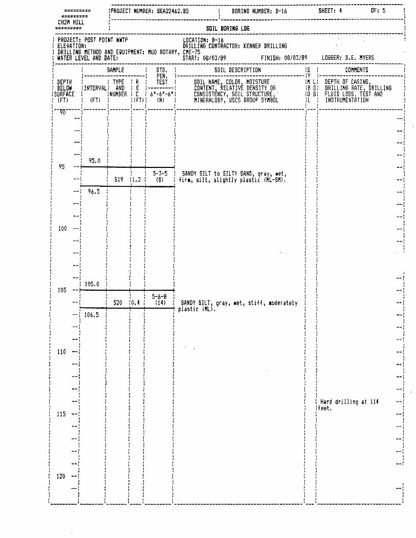
========= !PROJECT NUMBER: SEA22462.B5 BORING NUMBER: B-16 SHEET: 4 OF: 5 : ========= ' ' ' ' CH2M HILL ,----~~------------------------------ ---------------------------------------------------------------1 ' ' ========= : SOIL BORING LOG :
------------------------------------------------------------------------------------------------------------------------: PROJECT: POST POINT WWTP LOCATION: B-16 ELEVATION: DRILLING CONTRACTOR: KENNER DRILLING DRILL!N6 METHOD AND EQUIPMENT: MUD ROTARY, CME-75
: NATER LEVEL AND DATE: START: OB/03/89 FINISH: OB/03/89 LOSSER: D.E. MYERS :------------------------------------------------------------------------------------------------------------------------, : : SAMPLE : STD. : SOIL DESCRIPTION :s : COHHENTS I : l---------------------: PEN. 1--------------------------------------------lY :-----------------------------: I DEPTH : : TYPE : R : TEST SOIL HANE COLOR MOISTURE iM Li DEPTH OF CASING, : : BELOW :INTERVAL/ AND : E :---------: CONTENTJ AELATIVE DENSITY OR :BO: DRILLING RATE, ORILLINS :SURFACE :NUMBER : C : 6'-6'-6'i CONSISTtNCY, SOIL STRUCTUREl, iO 61 FLUID LOSSl TtST AND : (FTJ IFTI : (FT): INI : HINERALOSY, uses GROUP SYMBuL :L INSTRUNENTHTION l I I I ! l I I l l I l I \ ! I
:--95-----:--------:-------:----:---------:--------------------------------------------:---:-----------------------------: l --: l : : l : i --l
95
100
105
--: ' ' ' ' ' '
' ' --l
--: ' ' --: ' ' --: ' ' --l ' '
--: --:
--:
' ' --l ' ' ' ' ' ' 110 --: ' ' --1 ' ' --: ' ' --J ' ' --l ' ' 115 --: ' ' --: ' ' --l ' ' --: ' ' ' ' ' ' 120 --: ' ' --:
95.0
96.5
105. 0
106. 5
I f t l I t I I I I I ! I l I I I l 1 l I l I J ! ! I I I l 1 I
' ' S19 :1.2
' ' ' ' ' ' ' ' ,, ' ' ' ' ' ' ' S20 :o.4
' ' ' ' ' ' ' ' ' ' 5-3-5
(81
5-6-8 1141
SANDY SILT to SILTY SAND, gray, wet, firo, silt, slightly plastic IML-SMI.
SANDY SILT, gray, wet, stiff, 1oderately plastic lMLI.
Hard drilling at 114 lfeet.
--t
--: ' ' --:
--: ' ' --: ' ' --1
--: ' ' --: ' ' --:
' --: ' ' --l ' ' --1 ' ' --l
--: ' ' --: ' ' ' ' ' ' --: ' ' --l ' ' --: ' ' --: ' ' --l ' ' ' ' ' ' --: ' ' --: ' ' --!
' --:

' ' ' '
========= !PROJECT NUMBER: SEA224b2. B5 BORING NUMBER: B-16 SHEET: 5 OF: 5 : . ' ' ' ' ' r------------------------------------- ---------------------------------------------------------------1 ' '
========= CH2M HILL
========= l SOIL BORINS LOS : --------------------------------------------------------------------------------------------------~---------------------:
PROJECT: POST POINT WWTP LOCATION: B-16 ELEVATION: DRILLING CONTRACTOR: KENNER DRILLING OR!LLINS HETHOD AND EQUIPHENT: HUD ROTARY, CME-75 WATER LEVEL AND DATE: . START: 08/03/89 FINISH: 08/03/89 LOGSER: D.E. HYERS
l------------------------------------------------------------------------------------------------------------------------: ' ' ' '
l SAMPLE l STD. : SOIL DESCRIPTIOfl IS : COMMENTS : 1---------------------l PEN. 1--------------------------------------------lY t-----------------------------1
: DEPTH l BELOW :SURFACE : IFTI
l TYPE : R : TEST : SOIL NAHE 1 COLOR, MOISTURE :H L: DEPTH OF CASINS :INTERVAL: ANO : E :---------: CONTENT ttELATIVt DENSITY OR :Bo: DRILLING RATE, DRILLING
:NUMBER : C : 6'-b'-b": CONSISTfNCY, SOIL STRUCiURE 1 :o G: FLUID LOSS 1 TEST AND IFTl : IFTI: INI HINERALOSY' uses SROUP SYNBuL :L INSTRUHENTHTIDN
I ! I I
o 1:-~~~-+~~~-+~~\-~~~~I I I I : --12v ____ ' : :--~ru-BRADED-BRAQ£[-ii!H-s1rnn~-gray~------- ,--- :----------------------------- : l S21 10.3 60/3l l moist 1 very dense (GW), l : --l
125
130
135
140
145
' ' --:
' ' --1 ' '
--l :
--l
--l : ' ' ' ' --l ' ' ' ' ' ' --l
--: ' ' --:
--l ' ' ' ' ' ' ' ' --l ' ' ' ' ' ' --: ' ' ' ' ' ' --]
--: ' ' --1 ' '
--l
150 --: ' ' --:
120.3 End of Boring at 120.3 feet. ' ' --l
--: ' ' --l
' ' --l ' ' ' ' --: ' '
--J
--: ' ' --l ' ' --l :
--1 ' ' --! ' '
' ' ' ' --: ' ' --: ' ' ' ' --~----- ________ ,_~---- ---- --------- ----------------~-------------------------- --- _____________________________ 1
APPENDIX D Site Specific Seismic Response Analysis

October 6, 2010 | Page D-1 Field No. 00356-106-00
APPENDIX D
SITE-SPECIFIC SEISMIC RESPONSE ANALYSIS
General
A site-specific seismic site response analysis was completed for this project to evaluate the site
effects and to develop the ground surface design response spectra for use in the design and
analysis of the Bellingham Waste Water Treatment Plant improvements. The analysis was
completed and the design response spectra were developed in general accordance with the
procedures outlined in the 2009 International Building Code (IBC) in conjunction with Chapter 21
of the American Society of Civil Engineers (ASCE) 7-05 code. The following presents the general
approach in completing the analysis and development of the ground surface design spectra:
■ Developing a target rock outcrop response spectrum using the probabilistic ground motion
parameters determined from the 2002 United States Geological Survey (USGS) Probabilistic
Seismic Hazard Model.
■ Selecting representative earthquake time histories with source zones, magnitudes and site to
source distance that are consistent with the site regional tectonic setting and seismicity.
■ Scaling the selected time histories such that the average of their response spectra is a good
match to the target rock outcrop response spectrum.
■ Developing a soil models using subsurface soil information obtained from the explorations
completed at the project site, published shear wave velocity data in close proximity to the
project site, and geologic maps.
■ Propagating the scaled time histories through the soil models developed to assess the
amplification and damping effect of the site soils and developing response spectra at the
ground surface (top of the soil profile).
■ Establishing site specific design spectra using the results of the seismic response analysis per
ASCE 7-05 code.
DEVELOPMENT OF TARGET ROCK OUTCROP RESPONSE SPECTRUM
The USGS 2002 probabilistic seismic hazard deaggregation was completed for a 2 percent
probability of exceedance (PE) in 50 years and used to evaluate the seismic hazard at the project
area (122.514 W, 48.717 N). Using the spectral acceleration values estimated by the USGS for
periods between 0 and 2 seconds, a maximum considered earthquake (MCE) response spectrum
for the rock site condition was constructed and was used as the target spectrum in scaling our
selected input motions used in our site response analysis, as described below.
SITE-RESPONSE ANALYSIS
Selection of Input Ground Motions
In order to provide representative earthquake acceleration time histories for the site-response
analysis, we reviewed the percent contribution of the regional source zones to the estimated
seismic hazard at the project area using the USGS 2002 probabilistic seismic hazard

Page D-2 | October 6, 2010 | GeoEngineers, Inc. File No. 00356-106-00
deaggregation for ground motions with a 2 percent PE in 50 years. From the USGS deaggregation,
we observed that 54 percent was attributed to shallow gridded earthquakes, 30 percent was
attributed to deep gridded earthquakes, 15 percent was attributed to a magnitude 9 cascadia
subduction zone earthquake and 1 percent to the Devil’s Mountain Fault. Based on this
evaluation, we selected three intraplate subduction zone [IP] events, three shallow crustal events
[C], and one interface subduction zone [IF] event to be used as input ground motions for the site
response analysis. The ground motions selected using the criteria described above are presented
in Table D-1.
Scaling of Input Ground Motions
The selected input motion time histories were scaled prior to completing site response analysis.
Each selected time history was scaled so that its response spectrum is, on average, approximately
at the level of the target rock site response spectrum as defined above over the period range of
0 to 2 seconds. The scaling factors applied to each earthquake are shown in Table D-2. Figure D-1
shows the response spectra for the average of each orthogonal pair of scaled input motion time
histories, their average, and the target response spectrum used as a guide for scaling the input
motions.
TABLE D-1. GROUND MOTIONS
Earthquake,
Year
Recording
Station
Fault
Mechanism Magnitude
Distance
(km)
Scale
Factor
for
2475-YR
Event
Unscaled PGA
(orientation of
orthogonal
component)
Loma Prieta,
1989 Los Gatos Crustal 6.9 6 0.61
0.97 (NS)
0.59 (EW)
Nisqually,
2001 Maple Valley
Subduction
Zone,
Intraplate
6.8 75.2 4.80
0.08 (000)
0.10 (090)
Morgan Hill,
1984
USGS 1652
Anderson
Dam
(downstream)
Crustal 6.2 3.3 1.30
0.423 (250)
0.289 (340)
El Salvador,
2001
Santiago de
Maria
Subduction
Zone,
Intraplate
7.6 52.2 0.53
0.72 (090)
0.88 (360)
North Palm
Springs,
1986
CDMG 12204
San Jacinto -
Soboba
Crustal 6.1 22.9 2.00
0.250 (000)
0.239 (090)
Nisqually,
2001 Tacoma UPS
Subduction
Zone,
Intraplate
6.8 56.8 7.30
0.06 (000)
0.06 (090)
Synthetic N/A
Subduction
Zone,
Interface
9.2 N/A 1.52
0.09 (FP)
0.44 (FN)

October 6, 2010 | Page D-3 Field No. 00356-106-00
Soil Profile
A site-response model based on low-strain shear wave velocities was developed for this project.
The explorations completed at the project area extend to an approximate maximum depth of
125 feet and were terminated in very dense sand. A review of the regional geology at the site
shows that the site is located in an alluvial valley ranging from approximately 20 to 100 feet deep,
which is underlain by undifferentiated glacial drift deposits from the Vashon stage of the Frasier
glaciation. The glacial deposits are underlain by the Chuckanut Formation consisting of sandstone
and siltstone. The Chuckanut Formation generally dips towards Bellingham Bay at the northwest
portion of the site creating a bedrock bowl formation beneath the project area. The depth to
bedrock was assumed to range from 80 to 120 feet below the ground surface (bgs).
Based on the field data from the subsurface explorations the project area was split into two areas:
the west profile and the east profile. A preliminary sensitivity analysis was completed to compare
the site response using the west and east profiles. Because the west profile was determined to
show a higher site response, it was selected to be used in the more in-depth site-specific seismic
response analysis presented below. The results of the seismic analysis for the west profile were
then adjusted to determine the response spectrum for the east profile. A detailed description of the
soil profile used in the analysis is presented below.
The shear wave velocities of the soil for the site were determined using a seismic cone
penetrometer test (CPT) and standard penetration tests (SPT). The shear wave velocities of the
bedrock for the site were chosen based on published sonic wave velocity data specific to the
Chuckanut Formation (bedrock) near the project site reported in a USGS Technical Report (Brocher
and Ruebel, 1998)
In general, a mantle of fill soils, approximately 5 feet thick, overlies the project area and is
underlain by alluvial deposits. The thickness of the alluvial deposits were approximately 85 feet at
the west half of the project area. The alluvial deposits were assumed to consist of a 35-foot thick
younger alluvial deposit overlying a 40-foot thick layer of older alluvial deposit, of greater
consistency. Below the alluvial deposits undifferentiated glacial deposits were assumed to extend
to a depth of 120 feet below ground surface to the Chuckanut Formation (bedrock). The design
shear wave velocity profile used in D-MOD2000 for the seismic analysis are shown in Figure D-5.
Table D-2 summarizes the soil type, unit weights ( , shear wave velocity (Vs) and shear modulus
reduction and damping curves used in the D-MOD2000 model for the soil profile used in our
analysis.

Page D-4 | October 6, 2010 | GeoEngineers, Inc. File No. 00356-106-00
TABLE D-2. SOIL PROFILE MODEL
Depth (ft) Material Type
(pcf)
Vs
(ft/s)
Shear Modulus Reduction
and Damping Curves Start End
0 5 Sandy Silt to Silty Sand
(Fill) 125 850
EPRI: Deep, Cohesionless: 0 –
20 ft
5 20 Sand, Silt and Clay
(Younger Alluvium) 115 600
EPRI: Deep, Cohesionless: 0 –
20 ft
20 40 Sand, Silt and Clay
(Younger Alluvium) 115 600
EPRI: Deep, Cohesionless: 21
– 50 ft
40 60 Silt and Clay with Sand
(Older Alluvium) 115 700
Soil with PI=15 (Vucetic et al,
1991)
60 80 Silt and Clay with Sand
(Older Alluvium) 115 850
Soil with PI=15 (Vucetic et al,
1991)
80 100 Glacial Deposits 130 1200 EPRI: Deep, Cohesionless:
251 – 500 ft
100 120 Glacial Deposits 130 1500 EPRI: Deep, Cohesionless:
251 – 500 ft
120+
Chuckanut Formation
(bedrock) 150 2500 N/A
Site-Response Analysis and Computed Results
The site-response analysis was completed using the computer program D-MOD2000 (GeoMotions,
LLC. 2007). D-MOD2000 is a computer program for nonlinear, one-dimensional seismic-response
analysis.
Response spectra for 5 percent structural damping were developed for the site by propagating the
scaled input motions through the soil profile using D-MOD2000. We analyzed one soil profile
under a Maximum Considered Earthquake (MCE) event. For each profile 14 response spectra at
the ground surface were computed, one for each component of the seven input acceleration time
histories. Figure D-3 shows the MCE response spectra for each motion and their respective
computed average. The amplification factor (AF), which is the ratio of the surface spectral
acceleration to the scaled input rock spectral acceleration, was then calculated. Figure D-4 shows
the amplification factor for each motion and their respective computed average. The average AF at
the ground surface was then used to construct the site-specific design spectra for the project, as
described below.
Site-Specific Design Spectrum
The site-specific design spectrum for the project area was determined by applying the average AF
for the profile to the target rock spectrum in accordance with the procedures outlined in the ASCE
7-05 code, Sections 21.1.3 and 21.4. Figure D-5 shows the average AF computed by D-MOD2000
multiplied by the target rock spectrum determined from the USGS probabilistic seismic hazard

October 6, 2010 | Page D-5 Field No. 00356-106-00
deaggregation. The average soil shear wave velocity in the top 100 feet of the profile (Vs) was
determined for the soil profile. This soil property was then used to determine the site class per the
2009 IBC. Site class E was identified for the project site. For comparison purposes, the site class
E generalized design response spectrum and 80 percent of the site class E generalized response
spectrum per the ASCE 7-05 are shown on Figure D-5. The recommended design response
spectrum was developed based on the 80 percent site class E and site specific AF and is shown in
red on Figure D-5.
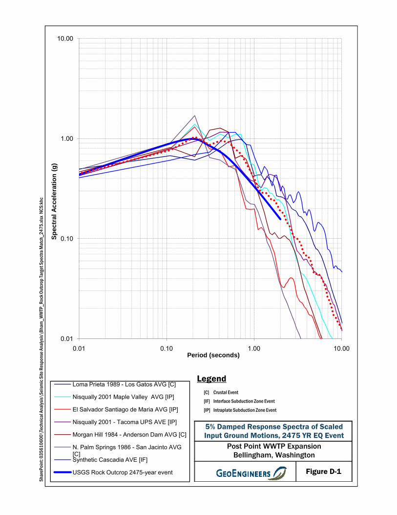
0.10
1.00
10.00
Sp
ectr
al
Accele
rati
on
(g
)
Spec
tra M
atch
_247
5.xls
x NC
S:kh
c
0.01
0.01 0.10 1.00 10.00Period (seconds)
Loma Prieta 1989 - Los Gatos AVG [C]
Nisqually 2001 Maple Valley AVG [IP]
El Salvador Santiago de Maria AVG [IP]
Nisqually 2001 - Tacoma UPS AVE [IP]
Morgan Hill 1984 - Anderson Dam AVG [C]
N. Palm Springs 1986 - San Jacinto AVG [C]Synthetic Cascadia AVE [IF]
USGS Rock Outcrop 2475-year event
Shar
ePoi
nt: 0
3561
0600
\Tec
hnica
l Ana
lysis\
Seism
icSi
teRe
spon
se A
nalys
is\Bh
am_W
WTP
_Roc
k Out
crop
Targ
et S
5% Damped Response Spectra of Scaled Input Ground Motions, 2475 YR EQ Event
Post Point WWTP ExpansionBellingham, Washington
Figure D-1
LegendCrustal Event
Interface Subduction Zone Event
Intraplate Subduction Zone Event
[C]
[IF]
[IP]

0
20
40
60
80
100
Dep
th (f
eet)
Vs P
rofile
_A
.xls
x N
CS
:khc
120
140
160
0 500 1000 1500 2000 2500 3000
Shear Wave Velocity (ft/s)
Best Estimate Vs
Share
Poin
t: 0
35610600\T
echnic
al A
naly
sis
\Seis
mic
Site
Response A
naly
sis
\Bham
_W
WT
P-
V
Design Shear Wave Velocity Profile
Post Point WWTP ExpansionBellingham, Washington
Figure D-2
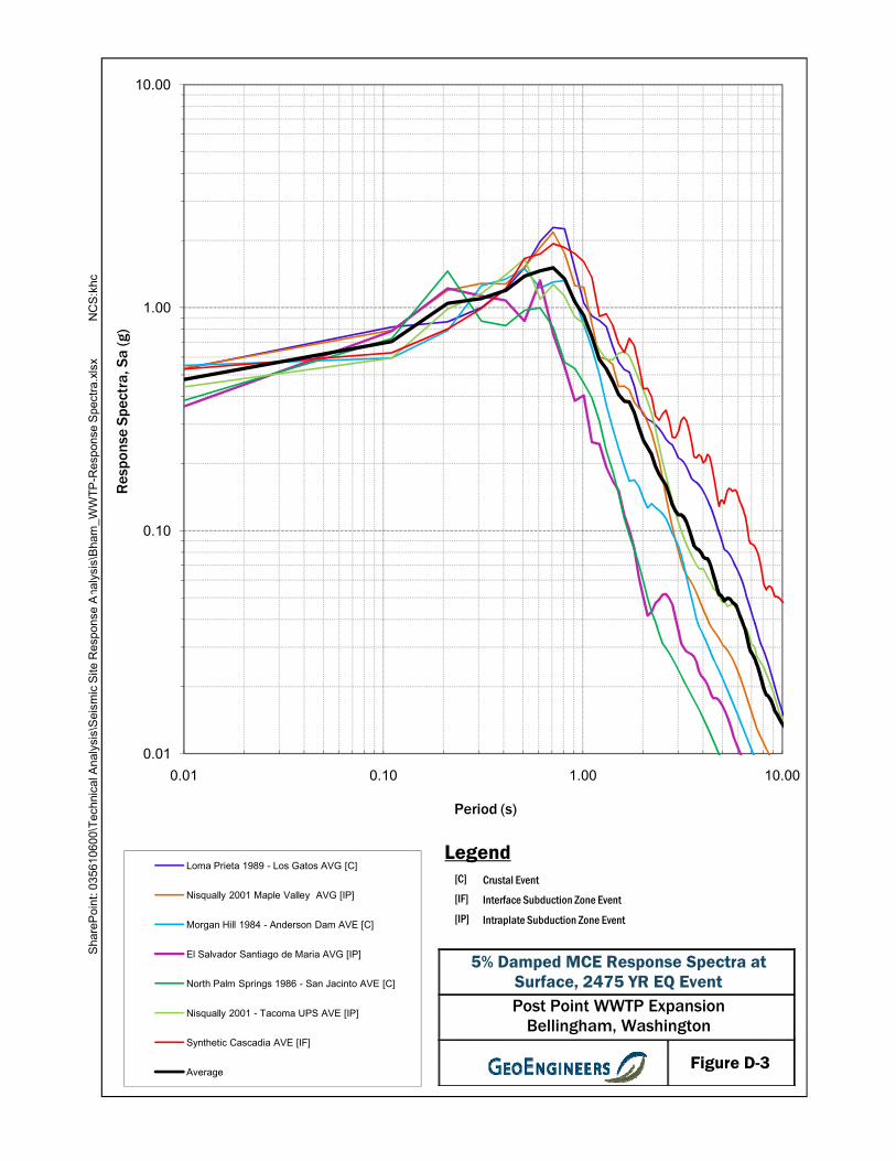
0.10
1.00
10.00
Res
pons
e S
pect
ra, S
a (g
)
naly
sis
\Bham
_W
WT
P-R
esponse S
pectr
a.x
lsx
NC
S:k
hc
0.01
0.01 0.10 1.00 10.00
Period (s)
Loma Prieta 1989 - Los Gatos AVG [C]
Nisqually 2001 Maple Valley AVG [IP]
Morgan Hill 1984 - Anderson Dam AVE [C]
El Salvador Santiago de Maria AVG [IP]
North Palm Springs 1986 - San Jacinto AVE [C]
Nisqually 2001 - Tacoma UPS AVE [IP]
Synthetic Cascadia AVE [IF]
Average
Share
Poin
t: 0
35610600\T
echnic
al A
naly
sis
\Seis
mic
Site
Response A
5% Damped MCE Response Spectra at Surface, 2475 YR EQ EventPost Point WWTP Expansion
Bellingham, Washington
Figure D-3
LegendCrustal Event
Interface Subduction Zone Event
Intraplate Subduction Zone Event
[C]
[IF]
[IP]

0.10
1.00
10.00
mpl
ifica
tion
Fact
or (S
urfa
ce S
a/
Scal
ed in
put R
ock
S a)
naly
sis
\Bham
_W
WT
P-R
esponse S
pectr
a.x
lsx
NC
S:k
hc
0.01
0.01 0.10 1.00 10.00
Am
Period (s)
Loma Prieta 1989 - Los Gatos AVG [C]
Nisqually 2001 Maple Valley AVG [IP]
Morgan Hill 1984 - Anderson Dam AVE [C]
El Salvador Santiago de Maria AVG [IP]
North Palm Springs 1986 - San Jacinto AVE [C]
Nisqually 2001 - Tacoma UPS AVE [IP]
Synthetic Cascadia AVE [IF]
Average
Share
Poin
t: 0
35610600\T
echnic
al A
naly
sis
\Seis
mic
Site
Response A
5% Damped MCE Amplification Factor at Surface, 2475 YR EQ EventPost Point WWTP Expansion
Bellingham, Washington
Figure D-4
LegendCrustal Event
Interface Subduction Zone Event
Intraplate Subduction Zone Event
[C]
[IF]
[IP]

0.10
1.00
10.00
Res
pons
e S
pect
ra (g
)
\Bham_W
WTP
‐Design Re
spon
se Spe
ctra.xlsx
NCS:khc
0.01
0.01 0.1 1 10Period (s)
MCE Response Spectrum for 2475 year Event
Average Best Estimate AF X Rock Outcrop (ASCE 7 Approach)
Site Class E General Response Spectrum (ASCE 7 Approach)
0.8 x Site Class E General Response Spectrum (ASCE 7 Approach)
5% Damped Site Specific MCE Response Spectra, 2475 YR EQ EventPost Point WWTP Expansion
Bellingham, Washington
Figure D-5
ShareP
oint: 035
6106
00\Techn
ical Analysis\SeismicSite
Respon
se Analysis\

APPENDIX E Report Limitations and Guidelines for Use

October 6, 2010 | Page E-1 Field No. 00356-106-00
REPORT LIMITATIONS AND GUIDELINES FOR USE1
This appendix provides information to help you manage your risks with respect to the use of this
report.
Geotechnical Services are Performed for Specific Purposes, Persons and Projects
This report has been prepared for the exclusive use of the City of Bellingham, Carollo Engineers,
and their authorized agents. This report may be made available to other members of the design
team. This report is not intended for use by others, and the information contained herein is not
applicable to other sites.
GeoEngineers structures our services to meet the specific needs of our clients. For example, a
geotechnical or geologic study conducted for a civil engineer or architect may not fulfill the needs
of a construction contractor or even another civil engineer or architect that are involved in the
same project. Because each geotechnical or geologic study is unique, each geotechnical
engineering or geologic report is unique, prepared solely for the specific client and project site. Our
report is prepared for the exclusive use of our Client. No other party may rely on the product of our
services unless we agree in advance to such reliance in writing. This is to provide our firm with
reasonable protection against open-ended liability claims by third parties with whom there would
otherwise be no contractual limits to their actions. Within the limitations of scope, schedule and
budget, our services have been executed in accordance with our Agreement with the Client and
generally accepted geotechnical practices in this area at the time this report was prepared. This
report should not be applied for any purpose or project except the one originally contemplated.
A Geotechnical Engineering or Geologic Report is Based on a Unique Set of Project-
specific Factors
This report has been prepared for the proposed Post Point Wastewater Treatment Plant Expansion
project to be located in Bellingham, Washington. GeoEngineers considered a number of unique,
project-specific factors when establishing the scope of services for this project and report. Unless
GeoEngineers specifically indicates otherwise, do not rely on this report if it was:
■ not prepared for you,
■ not prepared for your project,
■ not prepared for the specific site explored, or
■ completed before important project changes were made.
For example, changes that can affect the applicability of this report include those that affect:
■ the function of the proposed structure;
■ elevation, configuration, location, orientation or weight of the proposed structure;
1 Developed based on material provided by ASFE, Professional Firms Practicing in the Geosciences; www.asfe.org .

Page E-2 | October 6, 2010 | GeoEngineers, Inc. File No. 00356-106-00
■ composition of the design team; or
■ project ownership.
If important changes are made after the date of this report, GeoEngineers should be given the
opportunity to review our interpretations and recommendations and provide written modifications
or confirmation, as appropriate.
Subsurface Conditions Can Change
This geotechnical or geologic report is based on conditions that existed at the time the study was
performed. The findings and conclusions of this report may be affected by the passage of time, by
manmade events such as construction on or adjacent to the site, or by natural events such as
floods, earthquakes, slope instability or groundwater fluctuations. Always contact GeoEngineers
before applying a report to determine if it remains applicable.
Most Geotechnical and Geologic Findings are Professional Opinions
Our interpretations of subsurface conditions are based on field observations from widely spaced
sampling locations at the site. Site exploration identifies subsurface conditions only at those
points where subsurface tests are conducted or samples are taken. GeoEngineers reviewed field
and laboratory data and then applied our professional judgment to render an opinion about
subsurface conditions throughout the site. Actual subsurface conditions may differ, sometimes
significantly, from those indicated in this report. Our report, conclusions and interpretations should
not be construed as a warranty of the subsurface conditions.
Geotechnical Engineering Report Recommendations are Not Final
Do not over-rely on the preliminary construction recommendations included in this report. These
recommendations are not final, because they were developed principally from GeoEngineers’
professional judgment and opinion. GeoEngineers’ recommendations can be finalized only by
observing actual subsurface conditions revealed during construction. GeoEngineers cannot
assume responsibility or liability for this report's recommendations if we do not perform
construction observation.
Sufficient monitoring, testing and consultation by GeoEngineers should be provided during
construction to confirm that the conditions encountered are consistent with those indicated by the
explorations, to provide recommendations for design changes should the conditions revealed
during the work differ from those anticipated, and to evaluate whether or not earthwork activities
are completed in accordance with our recommendations. Retaining GeoEngineers for construction
observation for this project is the most effective method of managing the risks associated with
unanticipated conditions.
A Geotechnical Engineering or Geologic Report Could be Subject to Misinterpretation
Misinterpretation of this report by other design team members can result in costly problems. You
could lower that risk by having GeoEngineers confer with appropriate members of the design team
after submitting the report. Also retain GeoEngineers to review pertinent elements of the design
team's plans and specifications. Contractors can also misinterpret a geotechnical engineering or

October 6, 2010 | Page E-3 Field No. 00356-106-00
geologic report. Reduce that risk by having GeoEngineers participate in pre-bid and
preconstruction conferences, and by providing construction observation.
Do Not Redraw the Exploration Logs
Geotechnical engineers and geologists prepare final boring and testing logs based upon their
interpretation of field logs and laboratory data. To prevent errors or omissions, the logs included in
a geotechnical engineering or geologic report should never be redrawn for inclusion in architectural
or other design drawings. Only photographic or electronic reproduction is acceptable, but
recognize that separating logs from the report can elevate risk.
Give Contractors a Complete Report and Guidance
Some owners and design professionals believe they can make contractors liable for unanticipated
subsurface conditions by limiting what they provide for bid preparation. To help prevent costly
problems, give contractors the complete geotechnical engineering or geologic report, but preface it
with a clearly written letter of transmittal. In that letter, advise contractors that the report was not
prepared for purposes of bid development and that the report's accuracy is limited; encourage
them to confer with GeoEngineers and/or to conduct additional study to obtain the specific types of
information they need or prefer. A pre-bid conference can also be valuable. Be sure contractors
have sufficient time to perform additional study. Only then might an owner be in a position to give
contractors the best information available, while requiring them to at least share the financial
responsibilities stemming from unanticipated conditions. Further, a contingency for unanticipated
conditions should be included in your project budget and schedule.
Contractors are Responsible for Site Safety on Their Own Construction Projects
Our geotechnical recommendations are not intended to direct the contractor’s procedures,
methods, schedule or management of the work site. The contractor is solely responsible for job
site safety and for managing construction operations to minimize risks to on-site personnel and to
adjacent properties.
Read These Provisions Closely
Some clients, design professionals and contractors may not recognize that the geoscience
practices (geotechnical engineering or geology) are far less exact than other engineering and
natural science disciplines. This lack of understanding can create unrealistic expectations that
could lead to disappointments, claims and disputes. GeoEngineers includes these explanatory
“limitations” provisions in our reports to help reduce such risks. Please confer with GeoEngineers
if you are unclear how these “Report Limitations and Guidelines for Use” apply to your project or
site.
Geotechnical, Geologic and Environmental Reports Should Not be Interchanged
The equipment, techniques and personnel used to perform an environmental study differ
significantly from those used to perform a geotechnical or geologic study and vice versa. For that
reason, a geotechnical engineering or geologic report does not usually relate any environmental
findings, conclusions or recommendations; e.g., about the likelihood of encountering underground

Page E-4 | October 6, 2010 | GeoEngineers, Inc. File No. 00356-106-00
storage tanks or regulated contaminants. Similarly, environmental reports are not used to address
geotechnical or geologic concerns regarding a specific project.
Biological Pollutants
GeoEngineers’ Scope of Work specifically excludes the investigation, detection, prevention or
assessment of the presence of biological pollutants. Accordingly, this report does not include any
interpretations, recommendations, findings, or conclusions regarding the detecting, assessing,
preventing or abating of biological pollutants and no conclusions or inferences should be drawn
regarding biological pollutants, as they may relate to this project. The term “biological pollutants”
includes, but is not limited to, molds, fungi, spores, bacteria, and viruses, and/or any of their
byproducts.
If Client desires these specialized services, they should be obtained from a consultant who offers
services in this specialized field.