Geotechnical and Hydrogeological Investigation › ... › 39CD-20502-Geotechnical-Report.pdf ·...
61
15701 Robin’s Hill Road | London, Ontario | Canada t: +1.519.963.3000 | f: +1.519.963.1152 | exp.com Geotechnical and Hydrogeological Investigation Dillon Consulting Limited Project Name: Forest View Development 101 Meadowlily Road South London, Ontario Project Number: LON-00017363-GE Prepared By: EXP 15701 Robin’s Hill Road London, Ontario, N2V 0A5 t: +1.519.963.3000 f: +1.519.963.1152 Date Submitted: November 2019
Transcript of Geotechnical and Hydrogeological Investigation › ... › 39CD-20502-Geotechnical-Report.pdf ·...

15701 Robin’s Hill Road | London, Ontario | Canada
t: +1.519.963.3000 | f: +1.519.963.1152 | exp.com
Geotechnical and Hydrogeological Investigation Dillon Consulting Limited
Project Name:
Forest View Development
101 Meadowlily Road South
London, Ontario
Project Number:
LON-00017363-GE
Prepared By:
EXP
15701 Robin’s Hill Road
London, Ontario, N2V 0A5
t: +1.519.963.3000
f: +1.519.963.1152
Date Submitted:
November 2019
EXP Services Inc. Project Name: Forest View Development
Project Location: 101 Meadowlily Road South, London, ON
Project Number: LON-00017363-GE
Date: November 2019
i
Earth and Environmental Division - Geotechnical
Geotechnical Investigation Dillon Consulting Limited
Type of Document:
Final Report
Project Name:
Forest View Development
101 Meadowlily Road South
London, Ontario
Project Number:
LON-00017363-GE
Prepared and Reviewed By:
EXP Services Inc.
15701 Robins Hill Road
London, ON, N5V 0A5
Canada
t: +1.519.963.3000
f: +1.519.963.1152
_______________________________
Craig Swinson, P. Eng.
Geotechnical Services
_______________________________
Idib Sadoun, M.Sc., P.Eng.
Senior Engineer, Geotechnical Services
Date Submitted:
November 2019
EXP Services Inc. Project Name: Forest View Development
Project Location: 101 Meadowlily Road South, London, ON
Project Number: LON-00017363-GE
Date: November 2019
ii
Earth and Environmental Division - Geotechnical
1. Introduction and Background ......................................................................................................................................................1
1.1 Introduction ....................................................................................................................................................................1
1.2 Terms of Reference ........................................................................................................................................................1
2. Methodology ...............................................................................................................................................................................2
3. Site and Subsurface Conditions ...................................................................................................................................................3
3.1 Site Description ..............................................................................................................................................................3
3.2 Soil Stratigraphy – Meadowlily Road Services ................................................................................................................4
3.3 Soil Stratigraphy – Residential Subdivision .....................................................................................................................5
3.4 Groundwater Conditions ................................................................................................................................................6
3.5 Potable Groundwater .....................................................................................................................................................7
3.6 Methane Gas ..................................................................................................................................................................8
4. Discussion and Recommendations ..............................................................................................................................................9
4.1 General ...........................................................................................................................................................................9
4.2 Site Preparation ..............................................................................................................................................................9
4.3 Excavation and Groundwater Control ..........................................................................................................................10
4.4 Foundation Construction ..............................................................................................................................................12
4.5 Slab-On-Grade Construction .........................................................................................................................................13
4.6 Basement Construction ................................................................................................................................................14
4.7 Foundation Backfill .......................................................................................................................................................15
4.8 Site Servicing ................................................................................................................................................................16
4.9 Pumping Station ...........................................................................................................................................................17
4.10 Low Impact Development (LID) ....................................................................................................................................21
4.11 Earthquake Design Considerations ...............................................................................................................................22
4.12 Site Pavement Design ...................................................................................................................................................23
4.13 Curbs and Sidewalks .....................................................................................................................................................24
4.14 Inspection and Testing Requirements ..........................................................................................................................25
5. Hydrogeological Comments .......................................................................................................................................................26
6. General Comments ....................................................................................................................................................................29
Drawings ..........................................................................................................................................................................................30
Appendix A – Borehole Logs and Gradation Analysis Results ..........................................................................................................40
Appendix B – Inspecting and Testing Schedule................................................................................................................................42
Appendix C – Limitations and Use of Report ...................................................................................................................................41
Legal Notification .............................................................................................................................................................................44
EXP Services Inc. Project Name: Forest View Development
Project Location: 101 Meadowlily Road South, London, ON
Project Number: LON-00017363-GE
Date: November 2019
1
Earth and Environmental Division - Geotechnical
1. Introduction and Background
1.1 Introduction
EXP Services Inc. (EXP) was retained by Dillon Consulting Limited to carry out a geotechnical investigation and
prepare a geotechnical report relating to the proposed Forest View development to be located 101 Meadowlily Road
South in London, Ontario, hereinafter referred to as the ‘Site’.
It is understood that the development will consist of a condo development including single family residential lots
with basements, 4-plex townhomes, storm sewers and a sanitary pump station. Additionally, the development
includes a watermain and sanitary forcemain extension from the Site Commissioners Road East.
Based on an interpretation of the factual test hole data and a review of soil and groundwater information from test
holes advanced at the site, EXP has provided geotechnical engineering guidelines to support the proposed
development.
1.2 Terms of Reference
The geotechnical investigation was generally completed in accordance with the scope of work outlined via email
communications. Authorization to proceed with this investigation was received from Mr. Jason Johnson of Dillon
Consulting Limited through email correspondence.
The purpose of the investigation was to examine the existing soil and groundwater conditions at the site by advancing
a series of boreholes at the locations chosen by EXP and illustrated on the attached Borehole Location Plan
(Drawing 1).
Based on an interpretation of the factual borehole data, and a review of soil and groundwater information from test
holes excavated at the site, EXP has provided engineering guidelines for the geotechnical design and construction of
the proposed development. More specifically, this report provides comments on excavations, dewatering, site
preparation, foundations, slab-on-grade construction, bedding and backfill, earthquake design considerations,
pavement recommendations, and curbs and sidewalks.
This report is provided on the basis of the terms of reference presented above, and on the assumption that the design
will be in accordance with applicable codes and standards. If there are any changes in the design features relevant
to the geotechnical analyses, or if any questions arise concerning geotechnical aspects of the codes and standards,
this office should be contacted to review the design.
The information in this report in no way reflects on the environmental aspects of the soil. Should specific information
in this regard be needed, additional testing may be required.
Reference is made to Appendix D of this report, which contains further information necessary for the proper
interpretation and use of this report.
EXP Services Inc. Project Name: Forest View Development
Project Location: 101 Meadowlily Road South, London, ON
Project Number: LON-00017363-GE
Date: November 2019
2
Earth and Environmental Division - Geotechnical
2. Methodology
The fieldwork was conducted between August 20 and 21, 2019 and consisted of advancing seven (7) boreholes at
the approximate locations shown on Drawing 1. The boreholes are labeled as BH1 through BH7.
Prior to the investigation, buried service clearances were obtained for the boreholes by EXP.
The boreholes and dynamic cone tests were completed by a specialist drilling subcontractor under the full-time
supervision of EXP geotechnical staff. The boreholes were advanced utilizing a track-mounted drill rig equipped with
continuous flight solid and hollow stem augers, soil sampling and soil testing equipment. In each borehole, disturbed
soil samples were recovered at depth intervals of 0.75 m and 1.5 m using conventional split spoon sampling
equipment. Standard Penetration Tests (SPT’s) were also performed throughout the boreholes to assess the
compactness or consistency of the underlying soils, and to obtain representative samples. The boreholes are
described on the Borehole Logs (see Appendix A).
During the drilling, the stratigraphy within the boreholes was examined and logged in the field by EXP geotechnical
personnel.
Short-term groundwater levels within the open boreholes were observed. These observations pertaining to
groundwater conditions at the test hole locations are recorded in the borehole logs found in Appendix A. Following
the drilling, the boreholes were backfilled with the excavated materials and bentonite, to satisfy the requirements
of O.Reg. 903. A 50 mm diameter PVC monitoring well was installed in Boreholes BH3, BH5 and BH7. Details of the
monitoring well construction are provided on the attached Borehole Log. Groundwater measurements in the
monitoring well were obtained on August 28 and September 20, 2019.
Representative samples of the various soil strata encountered at the test locations were taken to our laboratory in
London for further examination by a geotechnical engineer and laboratory classification testing. Laboratory testing
for this investigation comprised routine moisture content determinations (results presented on the borehole logs in
Appendix A) and gradation analysis.
Samples remaining after the classification testing will be stored for a period of three months following the issuance
of report. After this time, they will be discarded unless prior arrangements have been made for longer storage.
The location of each test hole was established in the field in conjunction with reference to the proposed development
configuration. Ground surface elevation at each borehole location was interpolated based on topographic mapping
provided by AGM.
EXP Services Inc. Project Name: Forest View Development
Project Location: 101 Meadowlily Road South, London, ON
Project Number: LON-00017363-GE
Date: November 2019
3
Earth and Environmental Division - Geotechnical
3. Site and Subsurface Conditions
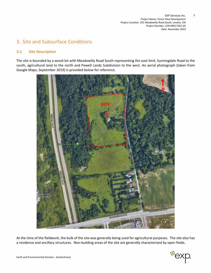
3.1 Site Description
The site is bounded by a wood-lot with Meadowlily Road South representing the east limit, Sunningdale Road to the
south, agricultural land to the north and Powell Lands Subdivision to the west. An aerial photograph (taken from
Google Maps, September 2019) is provided below for reference.
At the time of the fieldwork, the bulk of the site was generally being used for agricultural purposes. The site also has
a residence and ancillary structures. Non-building areas of the site are generally characterized by open fields.
SITE
N
EXP Services Inc. Project Name: Forest View Development
Project Location: 101 Meadowlily Road South, London, ON
Project Number: LON-00017363-GE
Date: November 2019
4
Earth and Environmental Division - Geotechnical
3.2 Soil Stratigraphy – Meadowlily Road Services
Boreholes BH1 and BH2 were located within the proposed sewer and watermain alignment on Meadowlily Road
South. The detailed stratigraphy encountered in each borehole is shown on the borehole logs found in Appendix A
and summarized in the following paragraphs. It must be noted that the boundaries of the soil indicated on the
borehole logs are inferred from non-continuous sampling and observations during excavation. These boundaries are
intended to reflect transition zones for geotechnical design and should not be interpreted as exact planes of
geological change.
Asphalt and Granular Fill
Asphalt was penetrated at the ground surface at the location of all boreholes, measuring between 75 mm and 100
mm in thickness.
Beneath the asphalt a layer of sand and gravel fill was encountered, measuring between 500 mm and 800 mm in
thickness. The granular fill was noted to be in a compact and moist state.
It should be noted that asphalt and fill quantities should not be established from the information provided at the
borehole locations only.
Clayey Silt Till
Beneath the asphalt and granular fill in each borehole was a stratum of glacial till. The till predominantly comprised
of clayey silt and was typically brown in colour. The till contained trace sand and gravel and has a stiff to very stiff
consistency (SPT N Values of 9 to 21 blows per 300 mm split spoon penetration). The in situ moisture content of the
till ranges from 6 to 16 percent indicating damp to wet conditions.
Sandy Silt
Beneath the till in Borehole BH2, sandy silt was encountered at a depth of 2.4 m below ground. The sandy silt was
generally described as brown in colour and dilatant. The sandy silt was compact with SPT N-values ranging from 12
to 26 blows per 300 mm sample spoon penetration. The sandy silt was in a wet state with in situ moisture contents
ranging from 17 to 22 percent.
EXP Services Inc. Project Name: Forest View Development
Project Location: 101 Meadowlily Road South, London, ON
Project Number: LON-00017363-GE
Date: November 2019
5
Earth and Environmental Division - Geotechnical
3.3 Soil Stratigraphy – Residential Subdivision
Boreholes BH3 to BH7 were located within the proposed residential subdivision at 101 Meadowlily Road South. The
detailed stratigraphy encountered in each borehole is shown on the borehole logs found in Appendix A and
summarized in the following paragraphs. It must be noted that the boundaries of the soil indicated on the borehole
logs are inferred from non-continuous sampling and observations during excavation. These boundaries are intended
to reflect transition zones for geotechnical design and should not be interpreted as exact planes of geological change.
Topsoil
The test holes were each surfaced with a layer of topsoil. The topsoil, generally described as brown/black sandy
loam, loose, and moist. The topsoil extended to depths ranging between about 75 mm and 400 mm.
In cultivated areas, it should be anticipated that surficial topsoil has been blended into the underlying subgrade soils.
In wooded areas, the topsoil may be thicker, and contain areas with significant roots.
Sandy Silt
Beneath the topsoil in each borehole, with the exception of Borehole BH4 and BH7, was a stratum of sandy silt. The
sandy silt was typically brown to grey in colour, weathered in the upper limits and contained dilatant layering
throughout. The compactness of the sandy silt is loose to very dense based on SPT N Values of 7 to 58 blows per 300
mm split spoon penetration. The in situ moisture content of the sandy silt ranges from 15 to 30 percent indicating
moist to wet conditions.
Clayey Silt
Within Borehole BH3, clayey silt was encountered below the sandy silt at a depth of about 3.7 m below ground
surface. The clayey silt was generally described as grey in colour and firm to stiff with SPT N-values ranging from 8
to 9 blow per 300 mm sample spoon penetration. The in situ moisture content of the clayey silt ranges from 18 to
24 percent, indicative of moist conditions.
Clayey Silt Till
Beneath the topsoil at Borehole BH4 was a stratum of glacial till. The till predominantly comprised of clayey silt and
was brown in colour. The till contained trace sand and gravel, and has a very stiff consistency (SPT N Values of 17 to
20 blows per 300 mm split spoon penetration). The in situ moisture content of the till ranges from 14 to 16 percent
indicating damp to moist conditions.
Silty Sand
Beneath the clayey silt at Borehole BH3 and the topsoil at Borehole BH7, a deposit of silty sand was encountered.
The silty sand was noted to be brown, weathered in the upper limits and contained clayey silt layering. The
compactness condition of the silty sand is loose to very dense, based on Standard Penetration Test (SPT) N-values
from 9 to greater than 50 blows per 300 mm penetration of the split-spoon sampler. The in situ moisture content of
the silty sand ranges from 3 to 27 percent, indicative of moist to wet conditions.
EXP Services Inc. Project Name: Forest View Development
Project Location: 101 Meadowlily Road South, London, ON
Project Number: LON-00017363-GE
Date: November 2019
6
Earth and Environmental Division - Geotechnical
3.4 Groundwater Conditions
Details of the groundwater conditions observed within the boreholes are provided on the attached Borehole Logs.
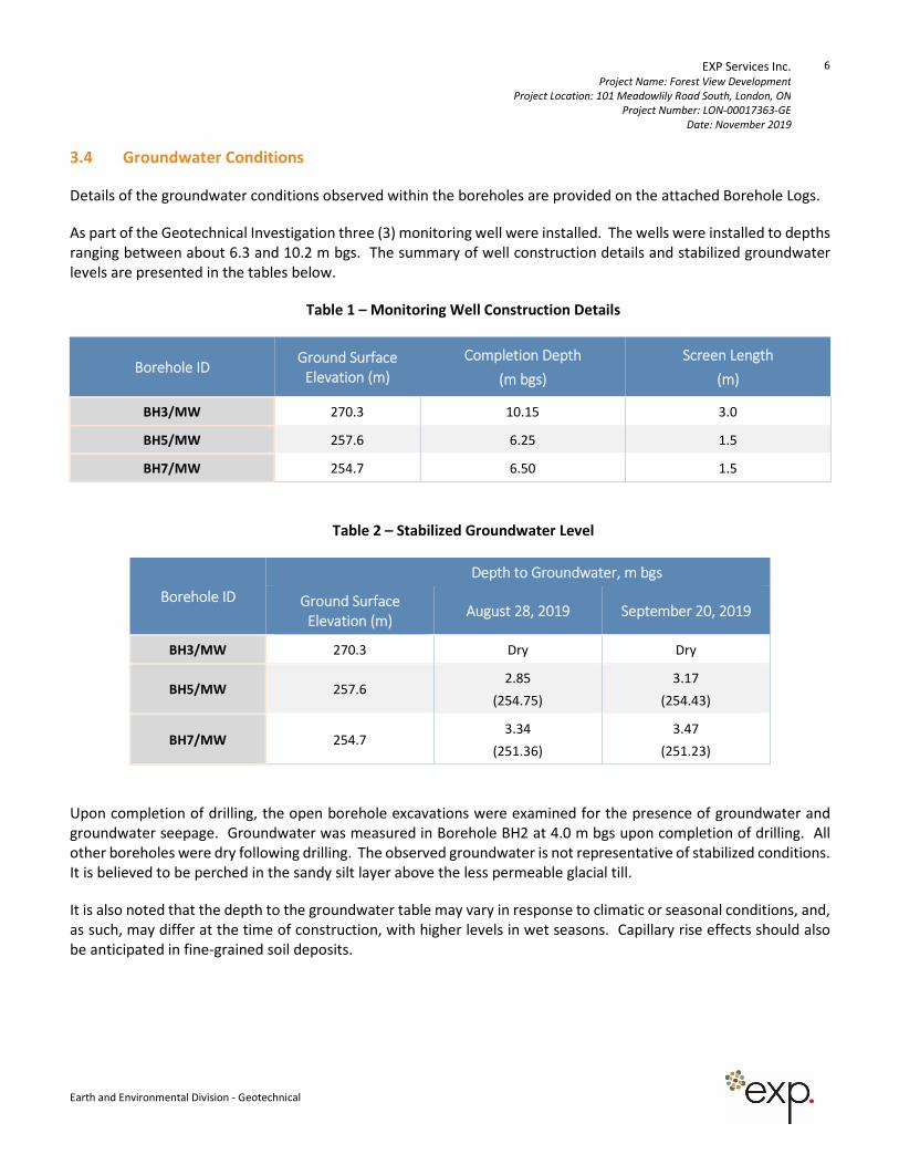
As part of the Geotechnical Investigation three (3) monitoring well were installed. The wells were installed to depths
ranging between about 6.3 and 10.2 m bgs. The summary of well construction details and stabilized groundwater
levels are presented in the tables below.
Table 1 – Monitoring Well Construction Details
Borehole ID Ground Surface
Elevation (m)
Completion Depth
(m bgs)
Screen Length
(m)
BH3/MW 270.3 10.15 3.0
BH5/MW 257.6 6.25 1.5
BH7/MW 254.7 6.50 1.5
Table 2 – Stabilized Groundwater Level
Borehole ID
Depth to Groundwater, m bgs
Ground Surface
Elevation (m) August 28, 2019 September 20, 2019
BH3/MW 270.3 Dry Dry
BH5/MW 257.6 2.85
(254.75)
3.17
(254.43)
BH7/MW 254.7 3.34
(251.36)
3.47
(251.23)
Upon completion of drilling, the open borehole excavations were examined for the presence of groundwater and
groundwater seepage. Groundwater was measured in Borehole BH2 at 4.0 m bgs upon completion of drilling. All
other boreholes were dry following drilling. The observed groundwater is not representative of stabilized conditions.
It is believed to be perched in the sandy silt layer above the less permeable glacial till.
It is also noted that the depth to the groundwater table may vary in response to climatic or seasonal conditions, and,
as such, may differ at the time of construction, with higher levels in wet seasons. Capillary rise effects should also
be anticipated in fine-grained soil deposits.
EXP Services Inc. Project Name: Forest View Development
Project Location: 101 Meadowlily Road South, London, ON
Project Number: LON-00017363-GE
Date: November 2019
7
Earth and Environmental Division - Geotechnical
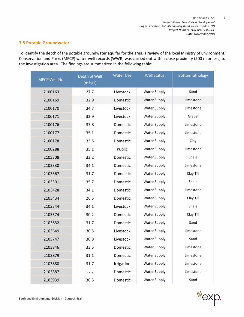
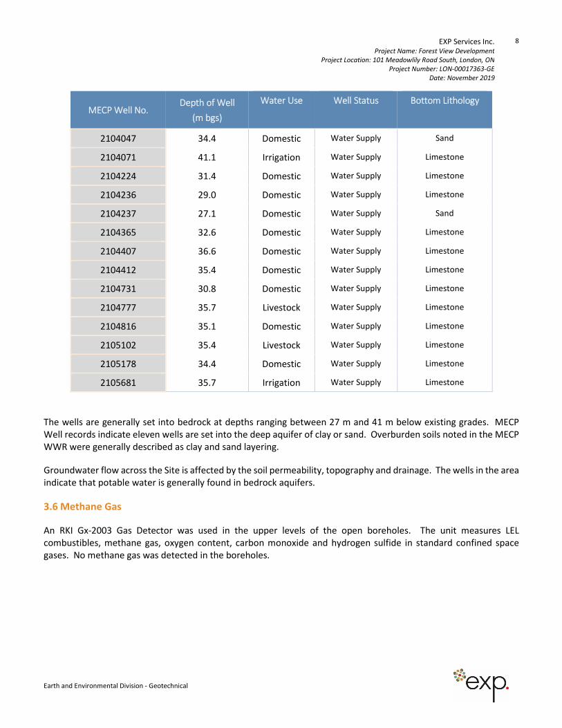
3.5 Potable Groundwater
To identify the depth of the potable groundwater aquifer for the area, a review of the local Ministry of Environment,
Conservation and Parks (MECP) water well records (WWR) was carried out within close proximity (500 m or less) to
the investigation area. The findings are summarized in the following table:
MECP Well No. Depth of Well
(m bgs)
Water Use Well Status Bottom Lithology
2100163 27.7 Livestock Water Supply Sand
2100169 32.9 Domestic Water Supply Limestone
2100170 34.7 Livestock Water Supply Limestone
2100171 32.9 Livestock Water Supply Gravel
2100176 37.8 Domestic Water Supply Limestone
2100177 35.1 Domestic Water Supply Limestone
2100178 33.5 Domestic Water Supply Clay
2100288 35.1 Public Water Supply Limestone
2103308 33.2 Domestic Water Supply Shale
2103330 34.1 Domestic Water Supply Limestone
2103367 31.7 Domestic Water Supply Clay Till
2103391 35.7 Domestic Water Supply Shale
2103428 34.1 Domestic Water Supply Limestone
2103434 26.5 Domestic Water Supply Clay Till
2103544 34.1 Livestock Water Supply Shale
2103574 30.2 Domestic Water Supply Clay Till
2103632 31.7 Domestic Water Supply Sand
2103649 30.5 Livestock Water Supply Limestone
2103747 30.8 Livestock Water Supply Sand
2103846 33.5 Domestic Water Supply Limestone
2103879 31.1 Domestic Water Supply Limestone
2103880 31.7 Irrigation Water Supply Limestone
2103887 37.2 Domestic Water Supply Limestone
2103939 30.5 Domestic Water Supply Sand
EXP Services Inc. Project Name: Forest View Development
Project Location: 101 Meadowlily Road South, London, ON
Project Number: LON-00017363-GE
Date: November 2019
8
Earth and Environmental Division - Geotechnical
MECP Well No. Depth of Well
(m bgs)
Water Use Well Status Bottom Lithology
2104047 34.4 Domestic Water Supply Sand
2104071 41.1 Irrigation Water Supply Limestone
2104224 31.4 Domestic Water Supply Limestone
2104236 29.0 Domestic Water Supply Limestone
2104237 27.1 Domestic Water Supply Sand
2104365 32.6 Domestic Water Supply Limestone
2104407 36.6 Domestic Water Supply Limestone
2104412 35.4 Domestic Water Supply Limestone
2104731 30.8 Domestic Water Supply Limestone
2104777 35.7 Livestock Water Supply Limestone
2104816 35.1 Domestic Water Supply Limestone
2105102 35.4 Livestock Water Supply Limestone
2105178 34.4 Domestic Water Supply Limestone
2105681 35.7 Irrigation Water Supply Limestone
The wells are generally set into bedrock at depths ranging between 27 m and 41 m below existing grades. MECP
Well records indicate eleven wells are set into the deep aquifer of clay or sand. Overburden soils noted in the MECP
WWR were generally described as clay and sand layering.
Groundwater flow across the Site is affected by the soil permeability, topography and drainage. The wells in the area
indicate that potable water is generally found in bedrock aquifers.
3.6 Methane Gas
An RKI Gx-2003 Gas Detector was used in the upper levels of the open boreholes. The unit measures LEL
combustibles, methane gas, oxygen content, carbon monoxide and hydrogen sulfide in standard confined space
gases. No methane gas was detected in the boreholes.
EXP Services Inc. Project Name: Forest View Development
Project Location: 101 Meadowlily Road South, London, ON
Project Number: LON-00017363-GE
Date: November 2019
9
Earth and Environmental Division - Geotechnical
4. Discussion and Recommendations
4.1 General
It is understood that the development will consist of a condo development including single family residential lots
with basements, 4-plex townhomes, storm sewers and a sanitary pump station. Additionally, the development
includes a watermain and sanitary forcemain extension from the Site Commissioners Road East.
Other associated features of the development may include access roads, new site services, and landscaped areas.
The following sections of this report provide geotechnical comments and recommendations regarding site
preparation, excavations and dewatering, foundations, slab-on-grade design, bedding and backfill, earthquake
design considerations, pavement design and curbs and sidewalks.
4.2 Site Preparation
General
Prior to placement of foundations, engineered fill, pipe bedding and/or road subgrade, all surficial topsoil, vegetation
and/or otherwise deleterious materials should be stripped. Thicker areas of topsoil may be anticipated in areas with
trees and/or heavy vegetative cover. It is anticipated that the surficial topsoil may be stockpiled on site for possible
reuse as landscaping fill.
Following the removal of topsoil, fill and other unsuitable soils, the exposed subgrade surfaces at subgrade design
level should be thoroughly proof-rolled with a heavy roller and examined by a Geotechnical Engineer. Any soft or
loose areas detected during the proof-rolling process should be sub-excavated and replaced with approved material.
It is recommended that construction traffic be minimized on the finished subgrade, and that the subgrade be sloped
to promote surface drainage and runoff.
In the building areas where the grade will be raised, the fill material should comprise imported granular or approved
onsite (excavated) material. The fill material should be inspected and approved by a Geotechnical Engineer, should
be placed in maximum 300 mm (12 inch) thick lifts and uniformly compacted to 100 percent Standard Proctor
Maximum Dry Density (SPMDD) within 3 percent of optimum moisture content. The geometric requirements for
engineered fill are provided on Drawing 2.
The natural and inorganic sandy silt and clayey silt materials on site would be suitable for reuse as engineered fill.
The material should be examined and approved by a Geotechnical Engineer prior to reuse.
In areas along the proposed roadways, fill material used to raise grades may comprise onsite excavated soils or
imported granular fill approved by the engineer. The fill should be placed in maximum 300 mm (12 inch) thick loose
lifts and uniformly compacted to 95/98 percent SPMDD within 3 percent of optimum moisture content in order to
provide adequate stability for the new pavements.
In situ compaction testing should be carried out during the fill placement to ensure that the specified compaction is
being achieved.
Excess materials should be removed from the site and disposed of in accordance with Ministry of the Environment,
Conservation and Parks (MECP) guidelines and requirements. Analytical sampling and testing may be required in
accordance with O. Reg. 153 for transportation and off-site disposal of excavated material.
EXP Services Inc. Project Name: Forest View Development
Project Location: 101 Meadowlily Road South, London, ON
Project Number: LON-00017363-GE
Date: November 2019
10
Earth and Environmental Division - Geotechnical
If imported fill material is used at the site, verification of the suitability of the fill may be required from an
environmental standpoint. Conventional geotechnical testing will not determine the suitability of the material in this
regard. Analytical testing and environmental site assessment may be required at the source. This will best be
assessed prior to the selection of the material source. A quality assurance program should be implemented to ensure
that the fill material will comply with the current (MECP) standards for placement and transportation.
The disposal of excavated materials must also conform to the MECP Guidelines and requirements. EXP can be of
assistance if an assessment of the materials is required.
4.3 Excavation and Groundwater Control
General
All work associated with design and construction relative to excavations must be carried out in accordance with Part
III of Ontario Regulation 213/91 under the Occupational Health and Safety Act (OHSA). OHSA specifies that where
workmen must enter a trench or excavation carried deeper than 1.2 m, the trench or excavation must be suitably
sloped and/or braced in accordance with the OHSA regulations.
The natural very stiff clayey silt till encountered at the site is generally classified as Type 2 soils while the sandy silt
and clayey silt and sandy silt materials are classified as Type 3 soils. Temporary excavation sidewalls which extend
through and terminate within Type 2 soil may be cut vertical in the bottom 1.2 m (4 ft), and cut back at an inclination
of 1 horizontal to 1 vertical or flatter above that level. Where excavations extend into or through Type 3 soil,
excavation side slopes must be cut back at a maximum inclination of about 1H:1V from the base of the excavation.
When excavations extend through Type 2 and Type 3 soils, the excavation should be cut as a Type 3 soil. In the event
groundwater egress loosens the sidewalls, flatter slopes of 3H:1V will be required and the soils should be considered
Type 4.
Geotechnical inspection at the time of excavation can confirm the soil type present.
It should be noted that the presence of cobbles and boulders in natural glacial deposits may influence the progress
of excavation and construction.
Excavation Support
The recommendations for side slopes given in the above section would apply to most of the conventional excavations
expected for the proposed development. However, in areas adjacent to buried services that are located above the
base of the excavations, side slopes may require support to prevent possible disturbance or distress to these
structures. This concept also applies to connections to existing services. In granular soils above the groundwater
and in cohesive natural soils, bracing will not normally be required if the structures are behind a 45-degree line drawn
up from the toe of the excavation. In wet sandy or silt soils, the setback should be about 3H to 1V if bracing is to be
avoided.
For support of excavations such as for any deep manholes, shoring such as sheeting or soldier piles and lagging can
be considered. The design and use of the support system should conform to the requirements set out in the most
recent version of the Occupational Health and Safety Act for Construction Projects and approved by the Ministry of
Labour. Excavations should conform to the guidelines set out in the proceeding section and the Safety Act.
The shoring should also be designed in accordance with the guidelines set out in the Canadian Foundation
Engineering Manual, 4th Edition. Soil-related parameters considered appropriate for a soldier pile and lagging
system are shown below.
EXP Services Inc. Project Name: Forest View Development
Project Location: 101 Meadowlily Road South, London, ON
Project Number: LON-00017363-GE
Date: November 2019
11
Earth and Environmental Division - Geotechnical
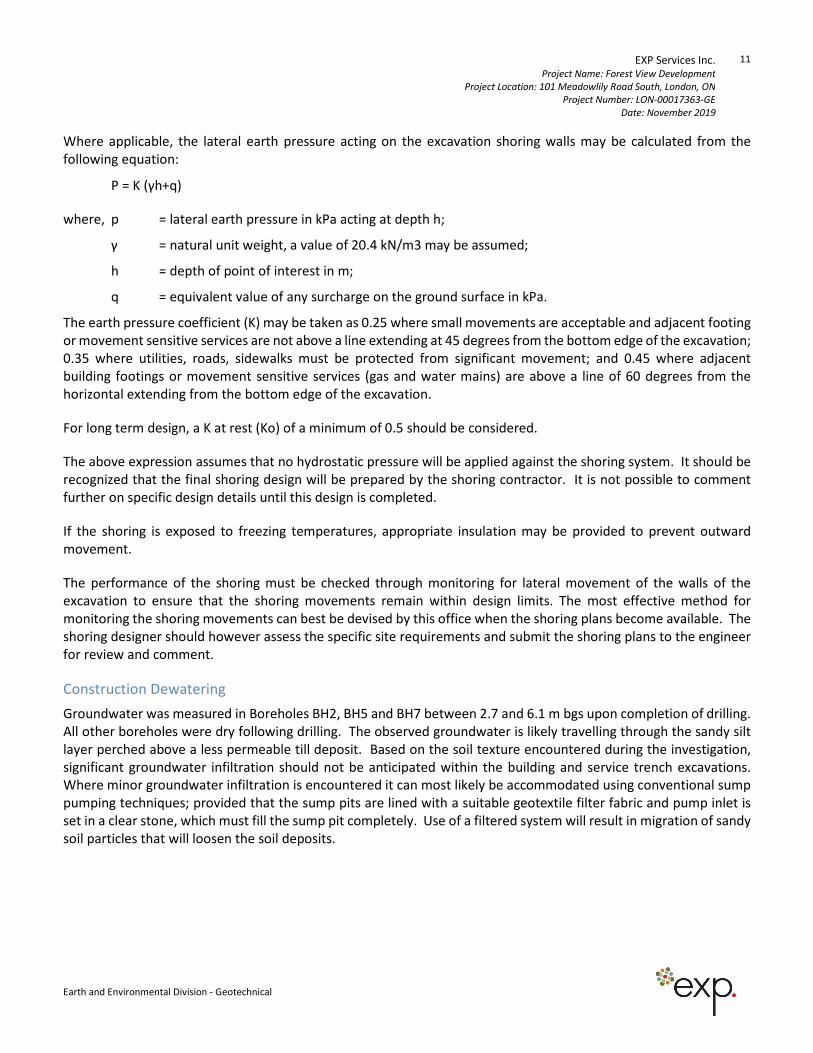
Where applicable, the lateral earth pressure acting on the excavation shoring walls may be calculated from the
following equation:
P = K (γh+q)
where, p = lateral earth pressure in kPa acting at depth h;
γ = natural unit weight, a value of 20.4 kN/m3 may be assumed;
h = depth of point of interest in m;
q = equivalent value of any surcharge on the ground surface in kPa.
The earth pressure coefficient (K) may be taken as 0.25 where small movements are acceptable and adjacent footing
or movement sensitive services are not above a line extending at 45 degrees from the bottom edge of the excavation;
0.35 where utilities, roads, sidewalks must be protected from significant movement; and 0.45 where adjacent
building footings or movement sensitive services (gas and water mains) are above a line of 60 degrees from the
horizontal extending from the bottom edge of the excavation.
For long term design, a K at rest (Ko) of a minimum of 0.5 should be considered.
The above expression assumes that no hydrostatic pressure will be applied against the shoring system. It should be
recognized that the final shoring design will be prepared by the shoring contractor. It is not possible to comment
further on specific design details until this design is completed.
If the shoring is exposed to freezing temperatures, appropriate insulation may be provided to prevent outward
movement.
The performance of the shoring must be checked through monitoring for lateral movement of the walls of the
excavation to ensure that the shoring movements remain within design limits. The most effective method for
monitoring the shoring movements can best be devised by this office when the shoring plans become available. The
shoring designer should however assess the specific site requirements and submit the shoring plans to the engineer
for review and comment.
Construction Dewatering
Groundwater was measured in Boreholes BH2, BH5 and BH7 between 2.7 and 6.1 m bgs upon completion of drilling.
All other boreholes were dry following drilling. The observed groundwater is likely travelling through the sandy silt
layer perched above a less permeable till deposit. Based on the soil texture encountered during the investigation,
significant groundwater infiltration should not be anticipated within the building and service trench excavations.
Where minor groundwater infiltration is encountered it can most likely be accommodated using conventional sump
pumping techniques; provided that the sump pits are lined with a suitable geotextile filter fabric and pump inlet is
set in a clear stone, which must fill the sump pit completely. Use of a filtered system will result in migration of sandy
soil particles that will loosen the soil deposits.
EXP Services Inc. Project Name: Forest View Development
Project Location: 101 Meadowlily Road South, London, ON
Project Number: LON-00017363-GE
Date: November 2019
12
Earth and Environmental Division - Geotechnical
However, if groundwater infiltration persists, more extensive dewatering measures may be required. EXP would be
pleased to provide further information in this regard, upon request.
The collected water should be discharged a sufficient distance away from the excavated area to prevent the discharge
water from returning to the excavation. Sediment control measures should be provided at the discharge point of
the dewatering system. Caution should also be taken to avoid any adverse impacts to the environment.
Although not anticipated for foundation excavations to conventional depths, it is important to mention that for any
projects requiring positive groundwater control with a removal rate of 50,000 litres to less than 400,000 litres per
day, an Environmental Activity and Sector Registry (EASR) or Permit to Take Water (PTTW) will be required. PTTW
applications are required for removal rates more than 400,000 L per day and will need to be approved by the MECP
per Sections 34 and 98 of the Ontario Water Resources Act R.S.O. 1990 and the Water Taking and Transfer Regulation
O. Reg. 387/04. It is noted that a standard geotechnical investigation will not determine all the groundwater
parameters which may be required to support the application. Accordingly, a detailed hydrogeological assessment
from a quantitative point of view may be required to estimate the quantity of water to be removed. EXP can assist
if the need arises.
4.4 Foundation Construction
The proposed residential units can be supported on conventional spread and strip footings founded below the topsoil
or unsuitable soils on the natural competent subgrade soils or engineered fill.
The following allowable bearing pressures (net stress increase) can be used on the natural, undisturbed sandy silt,
silty sand or clayey silt till soils below a typical depth of approximately 1.2 m below existing grade throughout the
site:
Bearing Resistance at Serviceability Limit States (SLS) 145 kPa (3,000 psf)
Factored Bearing Resistance at Ultimate Limit States (ULS) 215 kPa (4,500 psf)
Loose soil was encountered in Boreholes BH6 and BH7 near 1.2 m depth. If conventional footings are considered in
the area of these boreholes, a founding depth of 3.0 m bgs should be considered.
Where soil is removed and grades are to be raised or restored, engineered fill can be used for foundation support.
The geometric requirements for the fill placement are shown on Drawing 2, appended. The available SLS bearing
capacity for the engineered fill is 145 kPa (3,000 psf). For footings placed on engineered fill, it is recommended that
the strip footings be widened to 500 mm (20 inches) and contain nominal concrete reinforcing steel.
Verification of the soil conditions and the extent of reinforcement are best determined by the Geotechnical Engineer
at the time of excavation.
EXP Services Inc. Project Name: Forest View Development
Project Location: 101 Meadowlily Road South, London, ON
Project Number: LON-00017363-GE
Date: November 2019
13
Earth and Environmental Division - Geotechnical
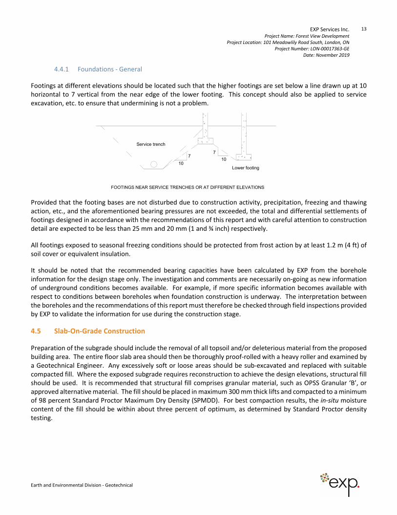
4.4.1 Foundations - General
Footings at different elevations should be located such that the higher footings are set below a line drawn up at 10
horizontal to 7 vertical from the near edge of the lower footing. This concept should also be applied to service
excavation, etc. to ensure that undermining is not a problem.
Provided that the footing bases are not disturbed due to construction activity, precipitation, freezing and thawing
action, etc., and the aforementioned bearing pressures are not exceeded, the total and differential settlements of
footings designed in accordance with the recommendations of this report and with careful attention to construction
detail are expected to be less than 25 mm and 20 mm (1 and ¾ inch) respectively.
All footings exposed to seasonal freezing conditions should be protected from frost action by at least 1.2 m (4 ft) of
soil cover or equivalent insulation.
It should be noted that the recommended bearing capacities have been calculated by EXP from the borehole
information for the design stage only. The investigation and comments are necessarily on-going as new information
of underground conditions becomes available. For example, if more specific information becomes available with
respect to conditions between boreholes when foundation construction is underway. The interpretation between
the boreholes and the recommendations of this report must therefore be checked through field inspections provided
by EXP to validate the information for use during the construction stage.
4.5 Slab-On-Grade Construction
Preparation of the subgrade should include the removal of all topsoil and/or deleterious material from the proposed
building area. The entire floor slab area should then be thoroughly proof-rolled with a heavy roller and examined by
a Geotechnical Engineer. Any excessively soft or loose areas should be sub-excavated and replaced with suitable
compacted fill. Where the exposed subgrade requires reconstruction to achieve the design elevations, structural fill
should be used. It is recommended that structural fill comprises granular material, such as OPSS Granular ‘B’, or
approved alternative material. The fill should be placed in maximum 300 mm thick lifts and compacted to a minimum
of 98 percent Standard Proctor Maximum Dry Density (SPMDD). For best compaction results, the in-situ moisture
content of the fill should be within about three percent of optimum, as determined by Standard Proctor density
testing.
7
1010
7
Lower footing
Service trench
FOOTINGS NEAR SERVICE TRENCHES OR AT DIFFERENT ELEVATIONS
EXP Services Inc. Project Name: Forest View Development
Project Location: 101 Meadowlily Road South, London, ON
Project Number: LON-00017363-GE
Date: November 2019
14
Earth and Environmental Division - Geotechnical
No special underfloor drains are required provided that the exterior grades are lower than the floor slab, and
positively sloped away from the slab. It is recommended that an impermeable soil seal such as clay, asphalt or
concrete be provided on the surface to minimize water infiltration from the exterior of the building. See Drawing 3
for Drainage and Backfill recommendations for slab-on-grade construction.
A moisture barrier, consisting of a 200 mm (8 in.) thick, compacted layer of 19 mm (3/4 in.) clear stone, should be
then placed between the prepared granular sub-base and the floor slab.
The installation and requirement of a vapor barrier under a concrete slab should conform to the flooring
manufacturer’s and designer’s requirements. Moisture emission testing will be required to determine the concrete
condition prior to flooring installation. In order to minimize the potential for excess moisture in the floor slab at the
time of the flooring installation, a concrete mixture with a low water-to-cement ratio (i.e., 0.45 to 0.55) should be
used. Chemical additives may be required at the time of placement to make the concrete workable, and should be
used in place of additional water at the point of placement. Ongoing liaison from this office will be required.
For slab on grade design, the modulus of subgrade reaction (k) can be taken as 25 MPa/m for the compacted stone
layer over the compacted granular subbase.
The water-to-cement ratio and slump of concrete utilized in the floor slabs should be strictly controlled to minimize
shrinkage of the slabs. Adequate joints should be provided in the floor slab to further control cracking. During
placement of concrete at the construction site, testing should be performed on the concrete.
4.6 Basement Construction
The main floor slab for the proposed basements may be constructed using conventional concrete slab-on-grade
techniques. The floor subgrade area should be stripped of any fill. The exposed area should be thoroughly proof
rolled with a heavy roller and any soft spots detected by this or any other means should be dug out and made good
with compactable fill, following the guidelines set out in Section 4.2.
Care should be taken to protect the subgrade below the floor slabs during construction, by limiting construction
traffic on the prepared subgrade soils. In addition, if the exposed subgrade soils are exposed to inclement weather
conditions (i.e. rain, snow, freezing conditions), some remedial works may be required to remove wet, soft, or
disturbed soils prior to stone and concrete placement.
A moisture barrier, consisting of a 200 mm (8 in.) thick, compacted layer of 19 mm (3/4 in.) clear, crushed stone,
should be placed between the prepared subgrade and the floor slab. For design, the modulus of subgrade reaction
(k) can be taken as 25 MPa/m for the compacted stone layer over the natural subgrade soils.
The water-to-cement ratio and slump of concrete utilized in the floor slab should be strictly controlled to minimize
shrinkage of the slab. Adequate joints should be provided in the floor slab to further control cracking. During
placement of concrete at the construction site, testing should be performed on the concrete.
EXP Services Inc. Project Name: Forest View Development
Project Location: 101 Meadowlily Road South, London, ON
Project Number: LON-00017363-GE
Date: November 2019
15
Earth and Environmental Division - Geotechnical
All basement walls should be damp-proofed and must be designed to resist a horizontal earth pressure ‘P’ at any
depth ‘h’ below the surface as given by the following expression:
P = K (γ h+q)
where, P = lateral earth pressure in kPa acting at depth h;
γ = natural unit weight, a value of 20.4 kN/m3 may be assumed;
h = depth of point of interest in m;
q = equivalent value of any surcharge on the ground surface in kPa.
K = earth pressure coefficient, assumed to be 0.4
Installation of perimeter drains is required for the basements at the Site. The above expression assumes that the
perimeter drainage system prevents the build-up of any hydrostatic pressure behind the wall. Suggestions for
permanent perimeter drainage are given on Drawing 4. Consideration should be given to the installation of an under
floor drainage system to collect and remove any water buildup beneath the structure.
4.7 Foundation Backfill
In general, the existing natural inorganic sandy silt and clayey silt till soils excavated from the foundation area should
be suitable for re-use as foundation wall backfill if the work is carried out during relatively dry weather. The materials
to be re-used should be within three percent of optimum moisture for best compaction results. Materials should be
stockpiled per their composition; i.e. sandy soils should not be mixed with clayey soils.
If the weather conditions are very wet during construction, then imported granular material such as OPSS Granular
'B' should be used. Site review by the geotechnical consultant may be advised.
The backfill must be brought up evenly on both sides of walls not designed to resist lateral earth pressures.
During construction, the fill surface around the perimeter of structures should be sloped in such a way that the
surface runoff water does not accumulate around the structure.
EXP Services Inc. Project Name: Forest View Development
Project Location: 101 Meadowlily Road South, London, ON
Project Number: LON-00017363-GE
Date: November 2019
16
Earth and Environmental Division - Geotechnical
4.8 Site Servicing
The subgrade soils beneath the water and sewer pipes which will service the Site are generally expected to comprise
sandy silt or clayey silt till. Where soils are removed, and grade is to be restored, granular should be used. For services
constructed on the natural soils or engineered fill, the bedding should conform to City of London and OPS Standards.
The bedding course may be thickened if portions of the subgrade become wet during excavation. Bedding aggregate
should be placed around the pipe to at least 300 mm (12 inch) above the pipe and be compacted to a minimum 95
percent SPMDD.
The bases of excavations which cut into and terminate in competent till are expected to remain stable for the short
construction period. Clear stone or crushed stone bedding may be used in the service trenches as bedding below
spring line of the pipe if necessary to assist groundwater control and provide stabilization to the excavation base in
wet silty soils. Geotextile should be wrapped around the stone bedding to minimize migration of fines.
The potential locations for use of stone bedding should be identified during construction and are expected to vary
across the site due to seasonal conditions and variations in the event of perched groundwater.
Water and sewer lines installed outside of heated areas should be provided with a minimum 1.2 m (4 ft.) of soil cover
for frost protection.
To minimize disturbance to the base, pipe laying should be carried out in short sections, with backfilling following
closely after laying and no section of trench should be left open overnight.
The trenches above the specified pipe bedding should be backfilled with inorganic on-site soils, placed in 300 mm
thick lifts and uniformly compacted to at least 95% SPMDD. For trench backfill within 1 meter below the roadway
subbase, the fill should be uniformly compacted to at least 98% SPMDD. A program of in situ density testing should
be set up to ensure that satisfactory levels of compaction are achieved.
Requirements for backfill in service trenches, etc. should also have regard for City of London requirements. A
summary of the general recommendations for trench backfill is presented on Drawing 5 and 6. A program of in situ
density testing should be set up to ensure that satisfactory levels of compaction are achieved.
Based on the results of this investigation, the majority of the excavated clayey silt till material may be used for
construction backfill provided that reasonable care is exercised in handling. In this regard, the material should be
within 3 percent of the optimum moisture as determined in the Standard Proctor density test and stockpiling of
material for prolonged periods of time should be avoided. This is particularly important if construction is carried out
in wet or otherwise adverse weather.
Soils excavated from below the stabilized groundwater table may be too wet for reuse as backfill unless adequate
time is allowed for drying, or if the material is blended with approved dry fill; otherwise, it may be stockpiled onsite
for reuse as landscape fill.
As noted previously, disposal of excavated materials off site should conform to current MECP guidelines.
EXP Services Inc. Project Name: Forest View Development
Project Location: 101 Meadowlily Road South, London, ON
Project Number: LON-00017363-GE
Date: November 2019
17
Earth and Environmental Division - Geotechnical
4.9 Pumping Station
The proposed sanitary pump station will be sited at the north end of the site. Once the surface topsoil is removed
and subgrade is exposed below the frost disturbed zone, the underlying soils consisted of compact, silt, silty sand
and sand and gravel underlain by generally stiff to very stiff silty clay.
The pump station building can be constructed on conventional strip and spread footings with a slab-on-grade floor,
in accordance with the general comments provided in the following paragraphs. The anticipated minor groundwater
ingress may require temporary control to facilitate construction.
For foundations set on the natural soils at depths of approximately 1.2 m below existing grades or approved structural
(granular) fill, the following allowable bearing pressures (net stress increase) can be used:
Bearing Resistance at Serviceability Limit States (SLS) 145 kPa (3,000 psf)
Factored Bearing Resistance at Ultimate Limit States (ULS) 215 kPa (4,500 psf)
Verification of the footing base soil conditions should be undertaken by the geotechnical engineer at the time of
excavation. It may be necessary to compact the sand soils prior to footing construction.
Flow Split Chamber / Valve Chambers
Details of the pumping station were not available at the time of preparing this report. The flow split chamber and
other valve chambers can be supported on the natural sandy silt up to about 4.0 m depth using a design SLS bearing
capacity of 145 kPa. The geotechnical resistance at Ultimate Limit States (ULS) is 215 kPa. If there are deeper
structures involved other than the wet well, EXP should be contacted to review the proposed soil bearing. Based on
the groundwater conditions observed in Borehole BH5 the sandy silt subgrade may be very moist to wet, and likely
sensitive to disturbance. Groundwater control with conventional sumps and shoring may be required. A mud-mat
over the exposed subgrade may be advised to ensure that the base remains in a stable condition.
The Wet Well
At the time of this investigation the exact depth of the wet well was unknown and will be determined through detail
design. However, shoring will likely be required during the wet well excavation. In addition to excavation support
through the compact upper materials, it will also assist with groundwater control. Shoring will function as a cut-off
wall for the water-bearing silty sand soils as well as limiting seepage into the excavation from possible wet seams.
Shoring comments have been provided in Section 4.3.
EXP Services Inc. Project Name: Forest View Development
Project Location: 101 Meadowlily Road South, London, ON
Project Number: LON-00017363-GE
Date: November 2019
18
Earth and Environmental Division - Geotechnical
Below Grade Structures
All below grade structure walls should be damp-proofed and must be designed to resist a horizontal earth pressure
‘p’ at any depth ‘h’ below the surface as given by the following expression:
P = K (γ h+q)
where, P = lateral earth pressure in kPa acting at depth h;
γ = natural unit weight, a value of 20.4 kN/m3 may be assumed;
h = depth of point of interest in m;
q = equivalent value of any surcharge on the ground surface in kPa.
K = earth pressure coefficient, assumed to be 0.4
All surface loads must be considered in the calculation of the lateral earth pressures.
Installation of perimeter drains is required for below grade structures. The above expression assumes that the
perimeter drainage system prevents the build-up of any hydrostatic pressure behind the wall.
Where hydrostatic pressures cannot be relieved, they must be added to the lateral earth pressures. This is discussed
further in the section below.
Waterproofing and Buoyancy Effects
Damp proofing of below-grade structures will be required. In addition, a waterstop membrane should be installed
between the footing pad and the foundation wall in order to prevent the flow of water between the base of the
foundation wall and the top of the footing.
For below grade structures, the installation of a perimeter drain is recommended to alleviate the build-up of any
hydrostatic pressure behind the wall. In the event perimeter drainage is not provided around the wet well and valve
chamber structures, waterproofing will also be required, and the structure must be designed to withstand uplift
forces due to buoyancy effects. For design purposes, the long term static groundwater table should be assumed at
a maximum depth of 1.5 m below the existing grades. The groundwater table could rise to near surface around the
deeper structures in wetter seasons. To resist the uplift forces when empty, the weight of the below grade structure
can be considered. Additional resistance to uplift can be achieved by extending the footings laterally around the
perimeter of the structure, such that the weight of the backfill around the structure overlying the footing extension
can also be used to resist the effects of uplift. Alternatively, the net weight of the structure can be increased. Further
comments pertaining to uplift calculations are provided on Drawing 7.
EXP Services Inc. Project Name: Forest View Development
Project Location: 101 Meadowlily Road South, London, ON
Project Number: LON-00017363-GE
Date: November 2019
19
Earth and Environmental Division - Geotechnical
Any portion of the structure which extends below the high water level should be designed to resist uplift due to
hydrostatic pressures. The magnitude of the hydrostatic uplift may be calculated using the following expression:
P = γ x d
where:
P = hydrostatic uplift pressure acting on the base of the structure (kPa);
γ = unit weight of water - use 9.8 kN/m3;
d = depth of base of the structure below the design high water level (m).
Where joints or connections in the structure occur, consideration should be given to providing suitable waterproofing
to restrict groundwater into the structure.
As discussed in the previous section, the lateral earth pressures are based on adequate drainage being provided to
prevent build-up of hydrostatic pressure. For structures below the ground water level, such as the wet well, lateral
earth pressures can be calculated using the following formula:
P = K (q + γsd1 + γsubd2) + γwd2
where, P = lateral earth pressure in kPa acting at depth d2;
γs = natural unit weight of moist soil, a value of 21.0 kN/m3 may be assumed;
γsub = submerged soil, 11 kN/m3;
γw = unit weight of water, 9.81 kN/m3;
d1 = depth to the groundwater level in m;
d2 = depth below the groundwater level in m;
q = equivalent value of any surcharge on the ground surface in kPa;
K = earth pressure coefficient, assumed to be 0.4.
All surface loads must be considered in the calculation of the lateral earth pressures.
EXP Services Inc. Project Name: Forest View Development
Project Location: 101 Meadowlily Road South, London, ON
Project Number: LON-00017363-GE
Date: November 2019
20
Earth and Environmental Division - Geotechnical
Slab-On-Grade Floor
The floor slab for the Pumping Station may be constructed using conventional concrete slab-on-grade techniques.
The floor slab subgrade should be prepared in accordance with the recommendations provided in Section 4.2.
No special underfloor drains are required provided that the exterior grades are lower than the floor slab, and
positively sloped away from the slab.
A moisture barrier, consisting of a 200 mm (8 in.) thick, compacted layer of 19 mm (3/4 in.) clear stone, should be
placed between the prepared subgrade and the floor slab. The installation and requirement of a vapor barrier under
the slab should conform to the flooring manufacturer’s and designer’s requirements. Moisture emission testing will
be required to determine the concrete condition prior to flooring installation. On-going liaison from this office will
be required.
For design, the modulus of subgrade reaction (k) can be taken as 30 MPa/m for the compacted stone layer over the
natural subgrade soils.
The floor slab of below grade structures can be cast directly on the natural soils. It is recommended to keep the floor
slab a minimum of 0.5 m above the groundwater table. Prior to placement of the slab, the exposed subgrade should
be assessed by a Geotechnical Engineer to ensure the absence of any soft soils. Any soft spots encountered will
require subexcavation and replacement with compacted fill. In order to minimize moisture flux through the below
grade structure floor slab, a minimum 10 mil thick poly barrier should be provided beneath the concrete slab.
The water-to-cement ratio and slump of concrete utilized in the floor slabs should be strictly controlled to minimize
shrinkage of the slabs. Adequate joints should be provided in the floor slab to further control cracking. During
placement of concrete at the construction site, testing should be performed on the concrete.
Foundation Backfill
In general, the natural soils excavated from the foundation and service trench areas should be suitable for reuse as
foundation wall backfill provided the work is carried out during relatively dry weather. Any excavated soils proposed
for re-use as backfill should be examined by a Geotechnical Engineer. The materials to be re-used should be within
three percent of optimum moisture for best compaction results. If the weather conditions are very wet during
construction, then imported granular material such as OPSS Granular 'B' should be used.
The backfill must be brought up evenly on both sides of walls not designed to resist lateral earth pressures. Drainage
and backfill recommendations are given in Drawing 4.
The fill surface around the perimeter of structures should be sloped in such a way that the surface runoff water does
not accumulate around the structure. It is recommended that an impermeable soil seal such as clay, asphalt or
concrete be provided on the surface to minimize water infiltration.
EXP Services Inc. Project Name: Forest View Development
Project Location: 101 Meadowlily Road South, London, ON
Project Number: LON-00017363-GE
Date: November 2019
21
Earth and Environmental Division - Geotechnical
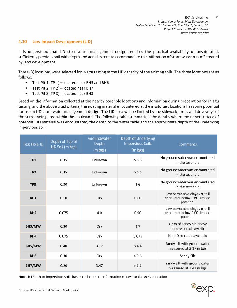
4.10 Low Impact Development (LID)
It is understood that LID stormwater management design requires the practical availability of unsaturated,
sufficiently pervious soil with depth and aerial extent to accommodate the infiltration of stormwater run-off created
by land development.
Three (3) locations were selected for in situ testing of the LID capacity of the existing soils. The three locations are as
follows:
• Test Pit 1 (TP 1) – located near BH5 and BH6
• Test Pit 2 (TP 2) – located near BH7
• Test Pit 3 (TP 3) – located near BH3
Based on the information collected at the nearby borehole locations and information during preparation for in situ
testing, and the above cited criteria, the existing material encountered at the in situ test locations has some potential
for use in LID stormwater management design. The LID area will be limited by the sidewalk, trees and driveways of
the surrounding area within the boulevard. The following table summarizes the depths where the upper surface of
potential LID material was encountered, the depth to the water table and the approximate depth of the underlying
impervious soil.
Test Hole ID Depth of Top of
LID Soil (m bgs)
Groundwater
Depth
(m bgs)
Depth of Underlying
Impervious Soils
(m bgs)
Comments
TP1 0.35 Unknown > 6.6 No groundwater was encountered
in the test hole
TP2 0.35 Unknown > 6.6 No groundwater was encountered
in the test hole
TP3 0.30 Unknown 3.6 No groundwater was encountered
in the test hole
BH1 0.10 Dry 0.60 Low permeable clayey silt till encounter below 0.60, limited
potential
BH2 0.075 4.0 0.90 Low permeable clayey silt till encounter below 0.90, limited
potential
BH3/MW 0.30 Dry 3.7 3.7 m of sandy silt above
impervious clayey silt
BH4 0.075 Dry 0.075 No LID material available
BH5/MW 0.40 3.17 > 6.6 Sandy silt with groundwater
measured at 3.17 m bgs
BH6 0.30 Dry > 9.6 Sandy Silt
BH7/MW 0.20 3.47 > 6.6 Sandy silt with groundwater
measured at 3.47 m bgs
Note 1: Depth to impervious soils based on borehole information closest to the in situ location
EXP Services Inc. Project Name: Forest View Development
Project Location: 101 Meadowlily Road South, London, ON
Project Number: LON-00017363-GE
Date: November 2019
22
Earth and Environmental Division - Geotechnical
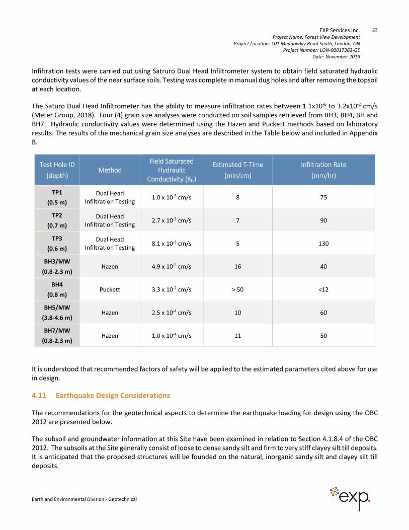
Infiltration tests were carried out using Satruro Dual Head Infiltrometer system to obtain field saturated hydraulic
conductivity values of the near surface soils. Testing was complete in manual dug holes and after removing the topsoil
at each location.
The Saturo Dual Head Infiltrometer has the ability to measure infiltration rates between 1.1x10⁻⁶ to 3.2x10⁻² cm/s
(Meter Group, 2018). Four (4) grain size analyses were conducted on soil samples retrieved from BH3, BH4, BH and
BH7. Hydraulic conductivity values were determined using the Hazen and Puckett methods based on laboratory
results. The results of the mechanical grain size analyses are described in the Table below and included in Appendix
B.
Test Hole ID
(depth) Method
Field Saturated
Hydraulic
Conductivity (Kfs)
Estimated T-Time
(min/cm)
Infiltration Rate
(mm/hr)
TP1
(0.5 m)
Dual Head
Infiltration Testing 1.0 x 10⁻³ cm/s 8 75
TP2
(0.7 m)
Dual Head
Infiltration Testing 2.7 x 10⁻³ cm/s 7 90
TP3
(0.6 m)
Dual Head
Infiltration Testing 8.1 x 10⁻³ cm/s 5 130
BH3/MW
(0.8-2.3 m) Hazen 4.9 x 10⁻⁵ cm/s 16 40
BH4
(0.8 m) Puckett 3.3 x 10⁻⁷ cm/s > 50 <12
BH5/MW
(3.8-4.6 m) Hazen 2.5 x 10⁻⁴ cm/s 10 60
BH7/MW
(0.8-2.3 m) Hazen 1.0 x 10⁻⁴ cm/s 11 50
It is understood that recommended factors of safety will be applied to the estimated parameters cited above for use
in design.
4.11 Earthquake Design Considerations
The recommendations for the geotechnical aspects to determine the earthquake loading for design using the OBC
2012 are presented below.
The subsoil and groundwater information at this Site have been examined in relation to Section 4.1.8.4 of the OBC
2012. The subsoils at the Site generally consist of loose to dense sandy silt and firm to very stiff clayey silt till deposits.
It is anticipated that the proposed structures will be founded on the natural, inorganic sandy silt and clayey silt till
deposits.
EXP Services Inc. Project Name: Forest View Development
Project Location: 101 Meadowlily Road South, London, ON
Project Number: LON-00017363-GE
Date: November 2019
23
Earth and Environmental Division - Geotechnical
Table 4.1.8.4.A. Site Classification for Seismic Site Response in OBC 2012 indicated that to determine the site
classification, the average properties in the top 30 m (below the lowest basement level) are to be used. The
boreholes advanced at this Site were excavated to a maximum depth of 9.6 m below existing grade. Therefore, the
Site Classification recommendation would be based on the available information as well as our interpretation of
conditions below the boreholes based on our knowledge of the soil conditions in the area.
Based on the above assumptions, interpretations in combination with the known local geological conditions, the Site
Class for the proposed development is “D” as per Table 4.1.8.4.A, Site Classification for Seismic Site Response, OBC
2012. Additional depth drilling may be advised to determine if the soil conditions below the current depth of
exploration can support a higher Site Classification.
4.12 Site Pavement Design
Areas to be paved should be stripped of all topsoil, fill, organics and other obviously unsuitable material. The exposed
subgrade must then be thoroughly proof-rolled. Any soft spots revealed by this or any other observations must be
over-excavated and backfilled with approved material. All fill required to backfill service trenches or to raise the
subgrade to design levels must conform to requirements outlined previously. Preferably, the natural inorganic
excavated soils should be used to maintain uniform subgrade conditions, provided adequate compaction can be
achieved.
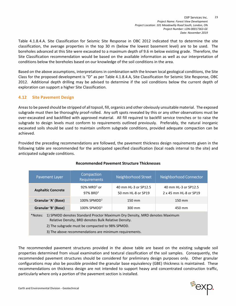
Provided the preceding recommendations are followed, the pavement thickness design requirements given in the
following table are recommended for the anticipated specified classification (local roads internal to the site) and
anticipated subgrade conditions.
Recommended Pavement Structure Thicknesses
Pavement Layer Compaction
Requirements Neighborhood Street Neighborhood Connector
Asphaltic Concrete 92% MRD1 or
97% BRD1
40 mm HL-3 or SP12.5
50 mm HL-8 or SP19
40 mm HL-3 or SP12.5
2 x 45 mm HL-8 or SP19
Granular ‘A’ (Base) 100% SPMDD1 150 mm 150 mm
Granular ‘B’ (Base) 100% SPMDD1 300 mm 450 mm
*Notes: 1) SPMDD denotes Standard Proctor Maximum Dry Density, MRD denotes Maximum
Relative Density, BRD denotes Bulk Relative Density.
2) The subgrade must be compacted to 98% SPMDD.
3) The above recommendations are minimum requirements.
The recommended pavement structures provided in the above table are based on the existing subgrade soil
properties determined from visual examination and textural classification of the soil samples. Consequently, the
recommended pavement structures should be considered for preliminary design purposes only. Other granular
configurations may also be possible provided the granular base equivalency (GBE) thickness is maintained. These
recommendations on thickness design are not intended to support heavy and concentrated construction traffic,
particularly where only a portion of the pavement section is installed.
EXP Services Inc. Project Name: Forest View Development
Project Location: 101 Meadowlily Road South, London, ON
Project Number: LON-00017363-GE
Date: November 2019
24
Earth and Environmental Division - Geotechnical
If construction is undertaken under adverse weather conditions (i.e., wet or freezing conditions) subgrade
preparation and granular sub-base requirements should be reviewed by the geotechnical engineer. If the sub-base
is set on wet or dilatant silty soils, a geotextile will be required. A woven type geotextile such as Terrafix 200W or
equivalent would be suitable for this application.
If only a portion of the pavement will be in place during construction, the granular subbase may have to be thickened,
and/or the subgrade improved with a geotextile separator or geogrid stabilizing layer. This is best determined in the
field during the site servicing stage of construction, prior to road construction.
Samples of both the Granular 'A' and Granular 'B' aggregates should be checked for conformance to OPSS 1010 and
City of London standards prior to utilization on Site, and during construction. The Granular 'B' subbase and the
Granular 'A' base courses must be compacted to 100 percent SPMDD.
The asphaltic concrete paving materials should conform to the requirements of OPSS 1150. The asphalt should be
placed in accordance with OPSS 310 and compacted to at least 97 percent of the Marshall mix design bulk relative
density or 92% of maximum relative density. A tack coat should be applied between the surface and binder asphalt
courses.
Good drainage provisions will optimize pavement performance. The finished pavement surface should be free of
depressions and should be sloped (preferably at a minimum grade of two percent) to provide effective surface
drainage toward catch basins. Surface water should not be allowed to pond adjacent to the outside edges of
pavement areas. In low areas, sub-drains should be installed to intercept excess subsurface moisture and prevent
subgrade softening, as shown on Drawing 8. This is particularly important in heavier traffic areas at the site entrances.
The locations and extent of sub-drainage required within the paved areas should be reviewed by this office in
conjunction with the proposed grading.
A program of in situ density testing must be carried out to verify that satisfactory levels of compaction are being
achieved.
To minimize the effects of differential settlements of service trench fill, it is recommended that wherever practical,
placement of binder asphalt be delayed for approximately six months after the granular sub-base is put down. The
surface course asphalt should be delayed for a further one year. Prior to the surface asphalt being placed, it is
recommended that a pavement evaluation be carried out on the base asphalt to identify repair areas or areas
requiring remedial works prior to surface asphalt being placed.
4.13 Curbs and Sidewalks
It is recommended that the concrete for curb and gutter and sidewalks should be proportioned, mixed, placed, and
cured in accordance with the requirements of OPSS 353, OPSS 1350 and City of London Specifications for Curbs and
Sidewalks (refer to current City of London Drawings).
During cold weather, the freshly placed concrete must be covered with insulating blankets to protect against freezing.
Three cylinders from each day's pour should be taken for compressive strength testing. Air entrainment,
temperature, and slump tests should be made from the same batch of concrete from which test cylinders are made.
The subgrade for the sidewalks should comprise undisturbed natural competent soil of well-compacted fill. A
minimum 150 mm thick layer of compacted Granular 'A' type aggregate should be placed beneath the sidewalk slabs.
EXP Services Inc. Project Name: Forest View Development
Project Location: 101 Meadowlily Road South, London, ON
Project Number: LON-00017363-GE
Date: November 2019
25
Earth and Environmental Division - Geotechnical
It is recommended that the Granular 'A' be compacted to a minimum 100 percent SPMDD, to provide adequate
support for the concrete sidewalk. Construction traffic should be kept off the placed curbs and sidewalks as they are
not designed to withstand heavy traffic load.
4.14 Inspection and Testing Requirements
An effective inspection and testing program is an essential part of construction monitoring. The Inspection and
Testing Program typically includes the following items:
• Subgrade examination prior to engineered fill placement;
• Inspection and Materials testing during engineered fill placement (full-time supervision is recommended)
and site servicing works, including soil sampling, laboratory testing (moisture contents and Standard Proctor
density test on the pipe bedding, trench backfill and engineered fill material), monitoring of fill placement,
and in situ density testing;
• Footing Base Examinations to confirm suitability to support the design bearing pressures; and, visual
examination of concrete reinforcing steel placement in footings set on engineered fill.
• Inspection and testing for underfloor subgrade and granular placement.
• Materials testing for concrete foundations, floor slab, curbs and sidewalks.
• Inspection and Materials testing during paved area construction, including subgrade examination of the
paved area subgrade soils following site servicing, laboratory testing (grain size analyses and Standard
Proctor density tests on the Granular A and B material placed on site roadways), and in situ density testing;
• Inspection and Materials testing for base and surface asphalt, including laboratory testing on asphalt
sampling and Benkelman beam deflection testing to confirm conformance to project specifications and
standards;
EXP would be pleased to prepare an inspection and testing work program prior to construction, incorporating the
above items.
EXP Services Inc. Project Name: Forest View Development
Project Location: 101 Meadowlily Road South, London, ON
Project Number: LON-00017363-GE
Date: November 2019
26
Earth and Environmental Division - Geotechnical
5. Hydrogeological Comments
Based on our understanding of the proposed development and the results of the current investigation, the following
paragraphs provide hydrogeological comments and discussion pertaining to the proposed development.
The Ministry of Environment, Conservation and Parks (MECP) Well Records for this area are summarized in Section
3.5. Groundwater information provided by MECP Records indicate that groundwater in the area is generally sourced
from bedrock aquifers (27 m to 41 m depth).
It is noted that the site is located within the community of Jackson (see map below) and municipal water will be
supplied to the development.
EXP Services Inc. Project Name: Forest View Development
Project Location: 101 Meadowlily Road South, London, ON
Project Number: LON-00017363-GE
Date: November 2019
27
Earth and Environmental Division - Geotechnical
Shallow groundwater flow across the site is typically affected by the soil permeability, topography and drainage.
Intermediate and deep aquifers are significantly less affected by surface conditions.
Based on the test holes information for the site, the proposed sewers and water mains are generally expected to be
set within the sandy silt or clayey silt till strata. Localized discontinuous lenses of wet silt and sand are typical within
the glaciolacustrine deposits, and could be contacted in the base of the service trench excavations along the servicing
alignment.
The texture of the predominant soils in the area is described as sandy silt or clayey silt till. The sandy silt or clayey
silt till deposits generally have a very low permeability and act as an effective barrier to minimize vertical and
horizontal groundwater movement.
Based on the results of the current investigation, no significant short- or long-term impact is anticipated on the
nearby wells, either quantitatively and qualitatively since the proposed inverts of the sewers are typically not deep
enough to penetrate into the underlying intermediate or deep aquifers, if any. Any temporary dewatering operations
which may be required to deal with minor seepage from localized pockets of sand and silt are not expected to cause
any long-term impacts to the aquifers which supply the nearby potable wells.
In any event, native backfill should be used where possible to minimize the change in hydraulic conductivity within
the service trenches. In the event the sewer excavations encounter any wet sandy soils, and for those areas where
the excavations extend below the stabilized shallow groundwater table, clay collars may be installed at strategic
locations, if necessary, as part of the contingency plan. This can be best assessed during the early stage of
construction by a Geotechnical Engineer.
The actual design and location of collars should be assessed at the final design phase and confirmed during
construction. However, the following comments are provided for guidance:
• Clay collar/plug shall be constructed of plastic clayey silt with moisture content about 3 % above optimum
moisture as determined by the standard Proctor density test.
• Excavation shall be carried out to the specified dimensions indicated on the sketches.
• The excavation shall be backfilled with compacted silty clay to at least 98 percent SPMDD to minimize
settlement.
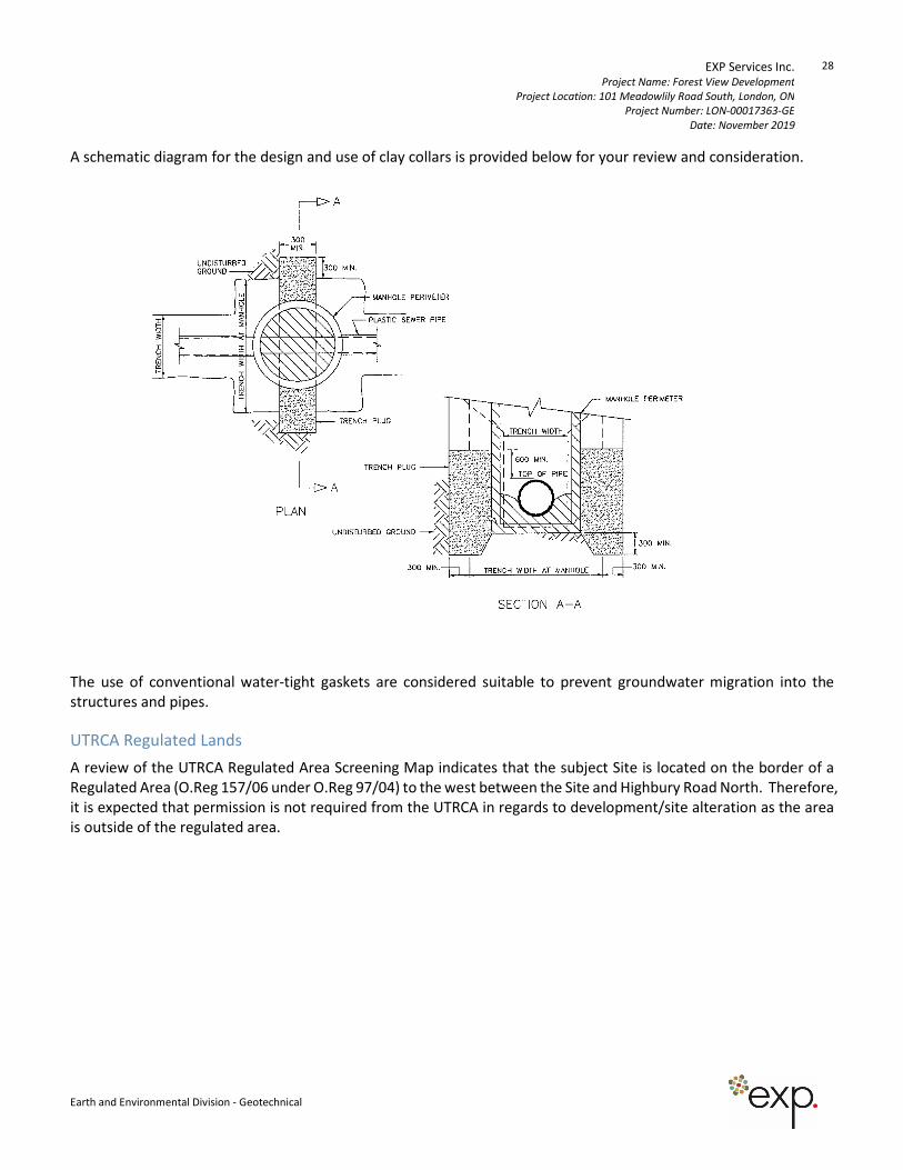
EXP Services Inc. Project Name: Forest View Development
Project Location: 101 Meadowlily Road South, London, ON
Project Number: LON-00017363-GE
Date: November 2019
28
Earth and Environmental Division - Geotechnical
A schematic diagram for the design and use of clay collars is provided below for your review and consideration.
The use of conventional water-tight gaskets are considered suitable to prevent groundwater migration into the
structures and pipes.
UTRCA Regulated Lands
A review of the UTRCA Regulated Area Screening Map indicates that the subject Site is located on the border of a
Regulated Area (O.Reg 157/06 under O.Reg 97/04) to the west between the Site and Highbury Road North. Therefore,
it is expected that permission is not required from the UTRCA in regards to development/site alteration as the area
is outside of the regulated area.
EXP Services Inc. Project Name: Applewood Subdivision, Block 1
Project Location: 660 Sunningdale Rd. E., London, ON
Project Number: LON-00017354-GE
Date: September 2019
29
Earth and Environmental Division - Geotechnical
6. General Comments
The information presented in this report is based on a limited investigation designed to provide information to
support an assessment of the current geotechnical conditions within the subject property. The conclusions and
recommendations presented in this report reflect site conditions existing at the time of the investigation.
Consequently, during the future development of the property, conditions not observed during this investigation may
become apparent. Should this occur, EXP Services Inc. should be contacted to assess the situation, and the need for
additional testing and reporting. EXP has qualified personnel to provide assistance in regards to any future
geotechnical and environmental issues related to this property.
Our undertaking at EXP, therefore, is to perform our work within limits prescribed by our clients, with the usual
thoroughness and competence of the engineering profession.
The comments given in this report are intended only for the guidance of design engineers. The number of test holes
required to determine the localized underground conditions between test holes affecting construction costs,
techniques, sequencing, equipment, scheduling, etc. would be much greater than has been carried out for design
purposes. Contractors bidding on or undertaking the works should in this light, decide on their own investigations,
as well as their own interpretations of the factual borehole results, so that they may draw their own conclusions as
to how the subsurface conditions may affect them.
EXP Services Inc. should be retained for a general review of the final design and specifications to verify that this report
has been properly interpreted and implemented. If not afforded the privilege of making this review, EXP Services Inc.
will assume no responsibility for interpretation of the recommendations in this report.
This report was prepared for the exclusive use of Dillon Consulting Limited and may not be reproduced in whole or
in part, without the prior written consent of EXP, or used or relied upon in whole or in part by other parties for any
purposes whatsoever. Any use which a third party makes of this report, or any part thereof, or any reliance on or
decisions to be made based on it, are the responsibility of such third parties. EXP Services Inc. accepts no
responsibility for damages, if any, suffered by any third party as a result of decisions made or actions based on this
report.
We trust this report is satisfactory for your purposes. Should you have any questions, please do not hesitate to
contact this office.

15701 Robin’s Hill Road | London, Ontario | Canada
t: +1.519.963.3000 | f: +1.519.963.1152 | exp.com
Drawings
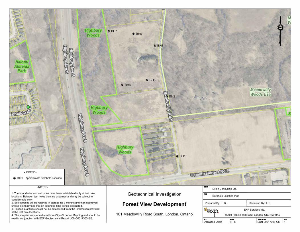
BH7
BH1
BH2
BH4
BH3
BH5
BH6
EXP Services Inc.
15701 Robin's Hill Road, London, ON, N5V 0A5
AUGUST 2019 NTS LON-00017363-GE 1
-NOTES-
1. The boundaries and soil types have been established only at test hole
locations. Between test holes they are assumed and may be subject to
considerable error.
2. Soil samples will be retained in storage for 3 months and then destroyed
unless client advises that an extended time period is required.
3. Topsoil quantities should not be established from the information provided
at the test hole locations.
4. The site plan was reproduced from City of London Mapping and should be
read in conjunction with EXP Geotechnical Report LON-00017363-GE.
Dillon Consulting Ltd.
-LEGEND-
Approximate Borehole Location
Borehole Location Plan
Prepared By: E.B. Reviewed By: I.S.
Geotechnical Investigation
Forest View Development
101 Meadowlily Road South, London, Ontario
BH1
AutoCAD SHX Text
DATE
AutoCAD SHX Text
SCALE
AutoCAD SHX Text
PROJECT NO.
AutoCAD SHX Text
DWG.
AutoCAD SHX Text
CLIENT
AutoCAD SHX Text
TITLE
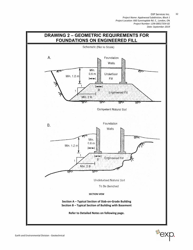
EXP Services Inc. Project Name: Applewood Subdivision, Block 1
Project Location: 660 Sunningdale Rd. E., London, ON
Project Number: LON-00017354-GE
Date: September 2019
32
Earth and Environmental Division - Geotechnical
DRAWING 2 – GEOMETRIC REQUIREMENTS FOR FOUNDATIONS ON ENGINEERED FILL
SECTION VIEW
Section A – Typical Section of Slab-on-Grade Building
Section B – Typical Section of Building with Basement
Refer to Detailed Notes on following page.
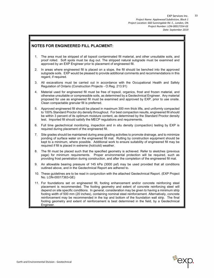
EXP Services Inc. Project Name: Applewood Subdivision, Block 1
Project Location: 660 Sunningdale Rd. E., London, ON
Project Number: LON-00017354-GE
Date: September 2019
33
Earth and Environmental Division - Geotechnical
NOTES FOR ENGINEERED FILL PLACMENT:
1. The area must be stripped of all topsoil contaminated fill material, and other unsuitable soils, and proof rolled. Soft spots must be dug out. The stripped natural subgrade must be examined and approved by an EXP Engineer prior to placement of engineered fill.
2. In areas where engineered fill is placed on a slope, the fill should be benched into the approved subgrade soils. EXP would be pleased to provide additional comments and recommendations in this regard, if required.
3. All excavations must be carried out in accordance with the Occupational Health and Safety Regulation of Ontario (Construction Projects - O.Reg. 213.91)
4. Material used for engineered fill must be free of topsoil, organics, frost and frozen material, and otherwise unsuitable or compressible soils, as determined by a Geotechnical Engineer. Any material proposed for use as engineered fill must be examined and approved by EXP, prior to use onsite. Clean compactable granular fill is preferred.
5. Approved engineered fill should be placed in maximum 300 mm thick lifts, and uniformly compacted to 100% Standard Proctor dry density throughout. For best compaction results, engineered fill should be within 3 percent of its optimum moisture content, as determined by the Standard Proctor density test. Imported fill should satisfy the MECP regulations and requirements.
6. Full time geotechnical monitoring, inspection and in situ density (compaction) testing by EXP is required during placement of the engineered fill.
7. Site grades should be maintained during area grading activities to promote drainage, and to minimize ponding of surface water on the engineered fill mat. Rutting by construction equipment should be kept to a minimum, where possible. Additional work to ensure suitability of engineered fill may be required if fill is placed in extreme (hot/cold) weather.
8. The fill must be placed such that the specified geometry is achieved. Refer to sketches (previous page) for minimum requirements. Proper environmental protection will be required, such as providing frost penetration during construction, and after the completion of the engineered fill mat.
9. An allowable bearing pressure of 145 kPa (3000 psf) may be used provided that all conditions outlined above, and in the Geotechnical Report are adhered to.
10. These guidelines are to be read in conjunction with the attached Geotechnical Report. (EXP Project No. LON-00017363-GE)
11. For foundations set on engineered fill, footing enhancement and/or concrete reinforcing steel placement is recommended. The footing geometry and extent of concrete reinforcing steel will depend on site specific conditions. In general, consideration may be given to having a minimum strip footing width of 500 mm (20 inches), containing nominal steel reinforcement. Alternatively, concrete reinforcement may be recommended in the top and bottom of the foundation wall strip. The final footing geometry and extent of reinforcement is best determined in the field, by a Geotechnical Engineer.
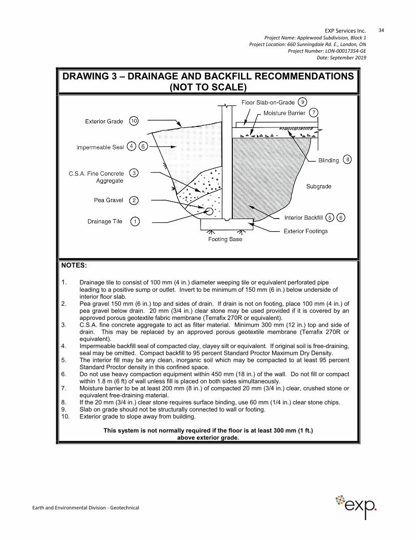
EXP Services Inc. Project Name: Applewood Subdivision, Block 1
Project Location: 660 Sunningdale Rd. E., London, ON
Project Number: LON-00017354-GE
Date: September 2019
34
Earth and Environmental Division - Geotechnical
DRAWING 3 – DRAINAGE AND BACKFILL RECOMMENDATIONS (NOT TO SCALE)
NOTES:
1. Drainage tile to consist of 100 mm (4 in.) diameter weeping tile or equivalent perforated pipe
leading to a positive sump or outlet. Invert to be minimum of 150 mm (6 in.) below underside of interior floor slab.
2. Pea gravel 150 mm (6 in.) top and sides of drain. If drain is not on footing, place 100 mm (4 in.) of pea gravel below drain. 20 mm (3/4 in.) clear stone may be used provided if it is covered by an approved porous geotextile fabric membrane (Terrafix 270R or equivalent).
3. C.S.A. fine concrete aggregate to act as filter material. Minimum 300 mm (12 in.) top and side of drain. This may be replaced by an approved porous geotextile membrane (Terrafix 270R or equivalent).
4. Impermeable backfill seal of compacted clay, clayey silt or equivalent. If original soil is free-draining, seal may be omitted. Compact backfill to 95 percent Standard Proctor Maximum Dry Density.
5. The interior fill may be any clean, inorganic soil which may be compacted to at least 95 percent Standard Proctor density in this confined space.
6. Do not use heavy compaction equipment within 450 mm (18 in.) of the wall. Do not fill or compact within 1.8 m (6 ft) of wall unless fill is placed on both sides simultaneously.
7. Moisture barrier to be at least 200 mm (8 in.) of compacted 20 mm (3/4 in.) clear, crushed stone or equivalent free-draining material.
8. If the 20 mm (3/4 in.) clear stone requires surface binding, use 60 mm (1/4 in.) clear stone chips. 9. Slab on grade should not be structurally connected to wall or footing. 10. Exterior grade to slope away from building.
This system is not normally required if the floor is at least 300 mm (1 ft.) above exterior grade.
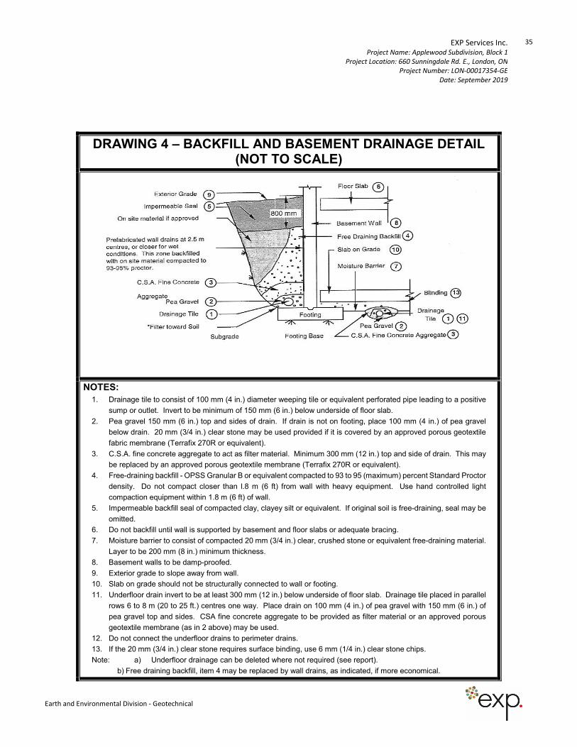
EXP Services Inc. Project Name: Applewood Subdivision, Block 1
Project Location: 660 Sunningdale Rd. E., London, ON
Project Number: LON-00017354-GE
Date: September 2019
35
Earth and Environmental Division - Geotechnical
DRAWING 4 – BACKFILL AND BASEMENT DRAINAGE DETAIL (NOT TO SCALE)
NOTES:
1. Drainage tile to consist of 100 mm (4 in.) diameter weeping tile or equivalent perforated pipe leading to a positive
sump or outlet. Invert to be minimum of 150 mm (6 in.) below underside of floor slab.
2. Pea gravel 150 mm (6 in.) top and sides of drain. If drain is not on footing, place 100 mm (4 in.) of pea gravel
below drain. 20 mm (3/4 in.) clear stone may be used provided if it is covered by an approved porous geotextile
fabric membrane (Terrafix 270R or equivalent).
3. C.S.A. fine concrete aggregate to act as filter material. Minimum 300 mm (12 in.) top and side of drain. This may
be replaced by an approved porous geotextile membrane (Terrafix 270R or equivalent).
4. Free-draining backfill - OPSS Granular B or equivalent compacted to 93 to 95 (maximum) percent Standard Proctor
density. Do not compact closer than l.8 m (6 ft) from wall with heavy equipment. Use hand controlled light
compaction equipment within 1.8 m (6 ft) of wall.
5. Impermeable backfill seal of compacted clay, clayey silt or equivalent. If original soil is free-draining, seal may be
omitted.
6. Do not backfill until wall is supported by basement and floor slabs or adequate bracing.
7. Moisture barrier to consist of compacted 20 mm (3/4 in.) clear, crushed stone or equivalent free-draining material.
Layer to be 200 mm (8 in.) minimum thickness.
8. Basement walls to be damp-proofed.
9. Exterior grade to slope away from wall.
10. Slab on grade should not be structurally connected to wall or footing.
11. Underfloor drain invert to be at least 300 mm (12 in.) below underside of floor slab. Drainage tile placed in parallel
rows 6 to 8 m (20 to 25 ft.) centres one way. Place drain on 100 mm (4 in.) of pea gravel with 150 mm (6 in.) of
pea gravel top and sides. CSA fine concrete aggregate to be provided as filter material or an approved porous
geotextile membrane (as in 2 above) may be used.
12. Do not connect the underfloor drains to perimeter drains.
13. If the 20 mm (3/4 in.) clear stone requires surface binding, use 6 mm (1/4 in.) clear stone chips.
Note: a) Underfloor drainage can be deleted where not required (see report).
b) Free draining backfill, item 4 may be replaced by wall drains, as indicated, if more economical.
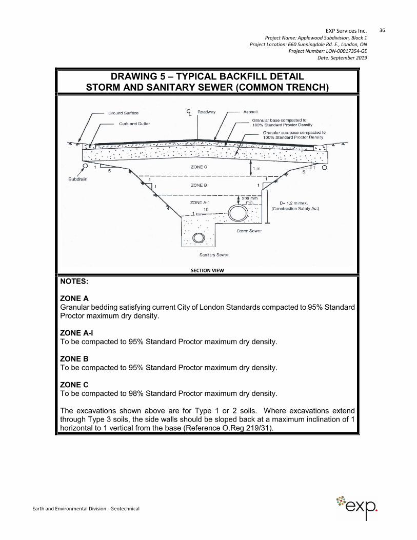
EXP Services Inc. Project Name: Applewood Subdivision, Block 1
Project Location: 660 Sunningdale Rd. E., London, ON
Project Number: LON-00017354-GE
Date: September 2019
36
Earth and Environmental Division - Geotechnical
DRAWING 5 – TYPICAL BACKFILL DETAIL STORM AND SANITARY SEWER (COMMON TRENCH)
SECTION VIEW
NOTES: ZONE A Granular bedding satisfying current City of London Standards compacted to 95% Standard Proctor maximum dry density. ZONE A-l To be compacted to 95% Standard Proctor maximum dry density. ZONE B To be compacted to 95% Standard Proctor maximum dry density. ZONE C To be compacted to 98% Standard Proctor maximum dry density. The excavations shown above are for Type 1 or 2 soils. Where excavations extend through Type 3 soils, the side walls should be sloped back at a maximum inclination of 1 horizontal to 1 vertical from the base (Reference O.Reg 219/31).
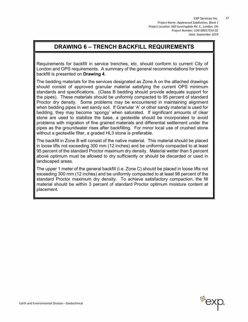
EXP Services Inc. Project Name: Applewood Subdivision, Block 1
Project Location: 660 Sunningdale Rd. E., London, ON
Project Number: LON-00017354-GE
Date: September 2019
37
Earth and Environmental Division - Geotechnical
DRAWING 6 – TRENCH BACKFILL REQUIREMENTS
Requirements for backfill in service trenches, etc. should conform to current City of London and OPS requirements. A summary of the general recommendations for trench backfill is presented on Drawing 4.
The bedding materials for the services designated as Zone A on the attached drawings should consist of approved granular material satisfying the current OPS minimum standards and specifications. (Class B bedding should provide adequate support for the pipes). These materials should be uniformly compacted to 95 percent of standard Proctor dry density. Some problems may be encountered in maintaining alignment when bedding pipes in wet sandy soil. If Granular ‘A’ or other sandy material is used for bedding, they may become ‘spongy’ when saturated. If significant amounts of clear stone are used to stabilize the base, a geotextile should be incorporated to avoid problems with migration of fine grained materials and differential settlement under the pipes as the groundwater rises after backfilling. For minor local use of crushed stone without a geotextile filter, a graded HL3 stone is preferable.
The backfill in Zone B will consist of the native material. This material should be placed in loose lifts not exceeding 300 mm (12 inches) and be uniformly compacted to at least 95 percent of the standard Proctor maximum dry density. Material wetter than 5 percent above optimum must be allowed to dry sufficiently or should be discarded or used in landscaped areas.
The upper 1 meter of the general backfill (i.e. Zone C) should be placed in loose lifts not exceeding 300 mm (12 inches) and be uniformly compacted to at least 98 percent of the standard Proctor maximum dry density. To achieve satisfactory compaction, the fill material should be within 3 percent of standard Proctor optimum moisture content at placement.
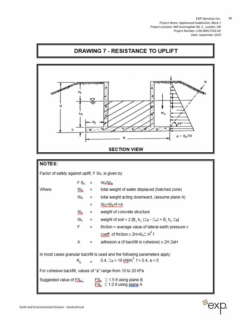
EXP Services Inc. Project Name: Applewood Subdivision, Block 1
Project Location: 660 Sunningdale Rd. E., London, ON
Project Number: LON-00017354-GE
Date: September 2019
38
Earth and Environmental Division - Geotechnical
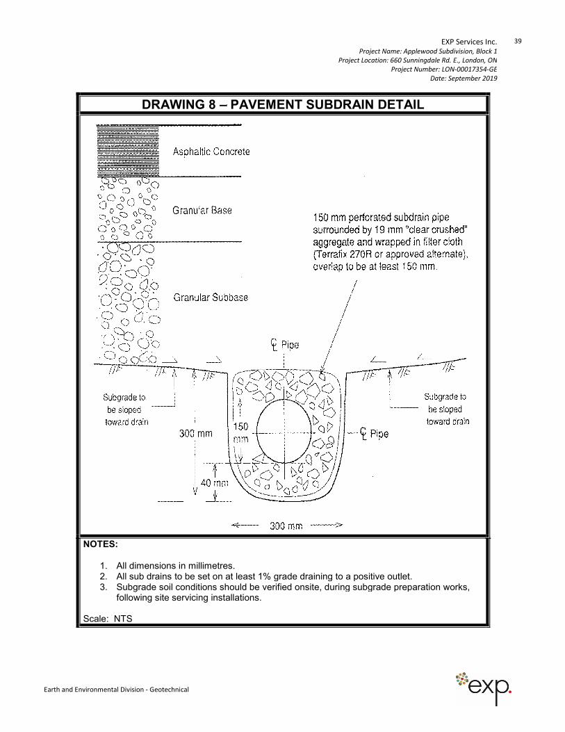
EXP Services Inc. Project Name: Applewood Subdivision, Block 1
Project Location: 660 Sunningdale Rd. E., London, ON
Project Number: LON-00017354-GE
Date: September 2019
39
Earth and Environmental Division - Geotechnical
DRAWING 8 – PAVEMENT SUBDRAIN DETAIL
NOTES:
1. All dimensions i n millimetres. 2. All sub drains to be set on at least 1% grade draining to a positive outlet. 3. Subgrade soil conditions should be verified onsite, during subgrade preparation works,
following site servicing installations. Scale: NTS

15701 Robin’s Hill Road | London, Ontario | Canada
t: +1.519.963.3000 | f: +1.519.963.1152 | exp.com
Appendix A – Borehole Logs and Gradation Analysis Results
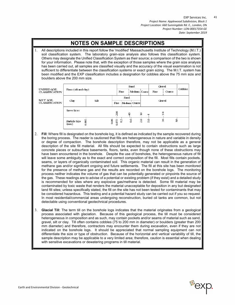
EXP Services Inc. Project Name: Applewood Subdivision, Block 1
Project Location: 660 Sunningdale Rd. E., London, ON
Project Number: LON-00017354-GE
Date: September 2019
41
Earth and Environmental Division - Geotechnical
NOTES ON SAMPLE DESCRIPTIONS
1. All descriptions included in this report follow the 'modified' Massachusetts Institute of Technology (M.I.T.) soil classification system. The laboratory grain-size analysis also follows this classification system. Others may designate the Unified Classification System as their source; a comparison of the two is shown for your information. Please note that, with the exception of those samples where the grain size analysis has been carried out, all samples are classified visually and the accuracy of the visual examination is not sufficient to differentiate between the classification systems or exact grain sizing. The M.I.T. system has been modified and the EXP classification includes a designation for cobbles above the 75 mm size and boulders above the 200 mm size.
2. Fill: Where fill is designated on the borehole log, it is defined as indicated by the sample recovered during
the boring process. The reader is cautioned that fills are heterogeneous in nature and variable in density or degree of compaction. The borehole description therefore, may not be applicable as a general description of the site fill material. All fills should be expected to contain obstructions such as large concrete pieces or subsurface basements, floors, tanks, even though none of these obstructions may have been encountered in the borehole. Despite the use of boreholes, the heterogeneous nature of fill will leave some ambiguity as to the exact and correct composition of the fill. Most fills contain pockets, seams, or layers of organically contaminated soil. This organic material can result in the generation of methane gas and/or significant ongoing and future settlements. The fill at this site has been monitored for the presence of methane gas and the results are recorded on the borehole logs. The monitoring process neither indicates the volume of gas that can be potentially generated or pinpoints the source of the gas. These readings are to advise of a potential or existing problem (if they exist) and a detailed study is recommended for sites where any explosive gas/methane is detected. Some fill material may be contaminated by toxic waste that renders the material unacceptable for deposition in any but designated land fill sites; unless specifically stated, the fill on the site has not been tested for contaminants that may be considered hazardous. This testing and a potential hazard study can be carried out if you so request. In most residential/commercial areas undergoing reconstruction, buried oil tanks are common, but not detectable using conventional geotechnical procedures.
3. Glacial Till: The term till on the borehole logs indicates that the material originates from a geological process associated with glaciation. Because of this geological process, the till must be considered heterogeneous in composition and as such, may contain pockets and/or seams of material such as sand, gravel, silt or clay. Till often contains cobbles (75 to 200 mm in diameter) or boulders (greater than 200 mm diameter) and therefore, contractors may encounter them during excavation, even if they are not indicated on the borehole logs. It should be appreciated that normal sampling equipment can not differentiate the size or type of obstruction. Because of the horizontal and vertical variability of till, the sample description may be applicable to a very limited area; therefore, caution is essential when dealing with sensitive excavations or dewatering programs in till material.
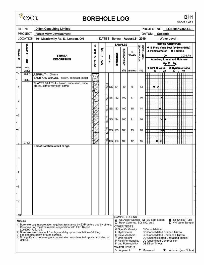
13
16
14
16
16
16
9
17
15
21
19
12
S1
S2
S3
S4
S5
S6
ASPHALT - 100 mmSAND AND GRAVEL - brown, compact, moist
CLAYEY SILT TILL - brown, trace sand, tracegravel, stiff to very stiff, damp
End of Borehole at 5.0 m bgs.
SS
SS
SS
SS
SS
SS
80
100
100
100
100
100
281.5
281.0
276.6
100 200 kPa
1) Borehole Log interpretation requires assistance by EXP before use by others.Borehole Log must be read in conjunction with EXP ReportLON00017363-GE.
2) Borehole was open to 4.3 m bgs and dry upon completion of drilling.3) bgs denotes below ground surface.4) No significant methane gas concentration was detected upon completion of
drilling.
CU Consolidated Undrained TriaxialCD Consolidated Drained Triaxial
K Lab PermeabilityP Field Permeability
Unit Weight
C Consolidation
AS Auger Sample
S Sieve AnalysisH HydrometerG Specific Gravity
OTHER TESTS
Rock Core (eg. BQ, NQ, etc.)ST Shelby TubeSS Split Spoon
SAMPLE LEGEND
Artesian (see Notes)MeasuredApparentWATER LEVELS
DS Direct Shear
VN Vane Sample
UU Unconsolidated Undrained TriaxialUC Unconfined Compression
NOTES
DEPTH
Dynamic ConeSPT N Value
SAMPLES
RECOVERY
S
DESCRIPTION
Torvane
P WW
PROJECT NO.
Field Vane Test (#=Sensitivity)PenetrometerD
EPTH
SHEAR STRENGTH
Water Level
CLIENT
LOCATION
BH1Sheet 1 of 1
N
BOREHOLE LOG
MOISTURE
CONTENT
(blows)
( m)~
(%)
Atterberg Limits and MoistureWW
DATUM
Field Vane Test (#=Sensitivity)
Forest View Development
10 20 30 40
P
SHEAR STRENGTH
Penetrometer
281.6
W
Dynamic Cone
L(m bgs)
Geodetic
LON-00017363-GE
DATES: Boring
DESCRIPTION
VALUE
DATES: Boring August 21, 2019
STRATA VALUENUMBER
DATUM
STRATA
LON-00017363-GE
NUMBER
TYPE
August 21, 2019
(%)
TorvaneS
Geodetic
STRATA
PLOT
ELEVATION W
PROJECT
SAMPLES
TYPE
SPT N Value
WELL
LOG
STRATA
PLOT
PROJECT NO.
ELEVATION
L
Atterberg Limits and Moisture
101 Meadowlily Rd. S., London, ON
Dillon Consulting Limited
WELL
LOG
Water Level
0
1
2
3
4
5
6
7
8
9
10
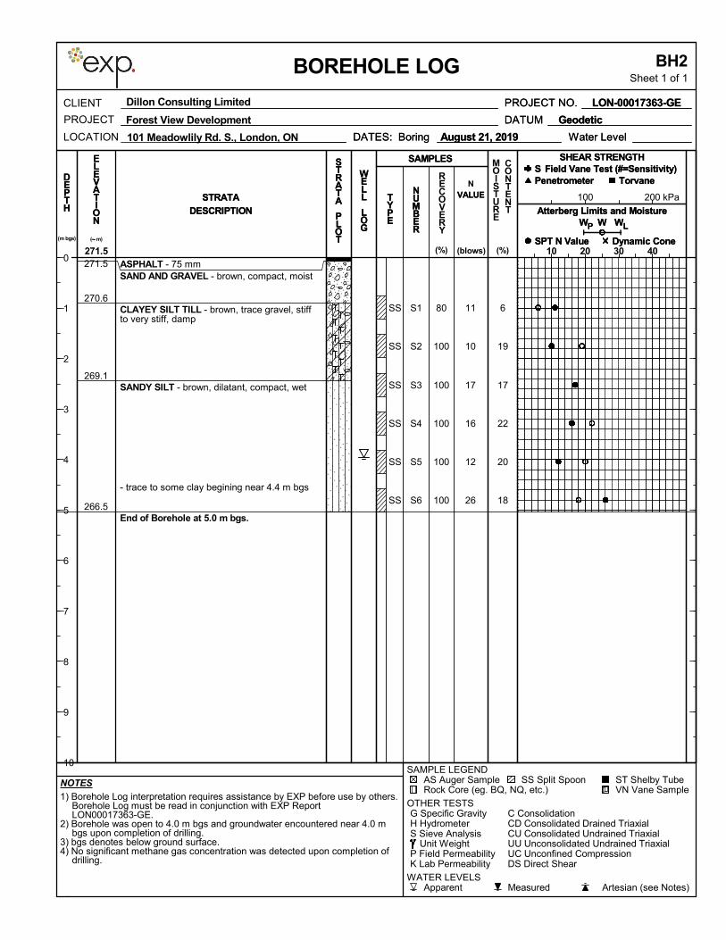
6
19
17
22
20
18
11
10
17
16
12
26
S1
S2
S3
S4
S5
S6
ASPHALT - 75 mmSAND AND GRAVEL - brown, compact, moist
CLAYEY SILT TILL - brown, trace gravel, stiffto very stiff, damp
SANDY SILT - brown, dilatant, compact, wet
- trace to some clay begining near 4.4 m bgs
End of Borehole at 5.0 m bgs.
SS
SS
SS
SS
SS
SS
80
100
100
100
100
100
271.5
270.6
269.1
266.5
100 200 kPa
1) Borehole Log interpretation requires assistance by EXP before use by others.Borehole Log must be read in conjunction with EXP ReportLON00017363-GE.
2) Borehole was open to 4.0 m bgs and groundwater encountered near 4.0 mbgs upon completion of drilling.
3) bgs denotes below ground surface.4) No significant methane gas concentration was detected upon completion of
drilling.
CU Consolidated Undrained TriaxialCD Consolidated Drained Triaxial
K Lab PermeabilityP Field Permeability
Unit Weight
C Consolidation
AS Auger Sample
S Sieve AnalysisH HydrometerG Specific Gravity
OTHER TESTS
Rock Core (eg. BQ, NQ, etc.)ST Shelby TubeSS Split Spoon
SAMPLE LEGEND
Artesian (see Notes)MeasuredApparentWATER LEVELS
DS Direct Shear
VN Vane Sample
UU Unconsolidated Undrained TriaxialUC Unconfined Compression
NOTES
DEPTH
Dynamic ConeSPT N Value
SAMPLES
RECOVERY
S
DESCRIPTION
Torvane
P WW
PROJECT NO.
Field Vane Test (#=Sensitivity)PenetrometerD
EPTH
SHEAR STRENGTH
Water Level
CLIENT
LOCATION
BH2Sheet 1 of 1
N
BOREHOLE LOG
MOISTURE
CONTENT
(blows)
( m)~
(%)
Atterberg Limits and MoistureWW
DATUM
Field Vane Test (#=Sensitivity)
Forest View Development
10 20 30 40
P
SHEAR STRENGTH
Penetrometer
271.5
W
Dynamic Cone
L(m bgs)
Geodetic
LON-00017363-GE
DATES: Boring
DESCRIPTION
VALUE
DATES: Boring August 21, 2019
STRATA VALUENUMBER
DATUM
STRATA
LON-00017363-GE
NUMBER
TYPE
August 21, 2019
(%)
TorvaneS
Geodetic
STRATA
PLOT
ELEVATION W
PROJECT
SAMPLES
TYPE
SPT N Value
WELL
LOG
STRATA
PLOT
PROJECT NO.
ELEVATION
L
Atterberg Limits and Moisture
101 Meadowlily Rd. S., London, ON
Dillon Consulting Limited
WELL
LOG
Water Level
0
1
2
3
4
5
6
7
8
9
10
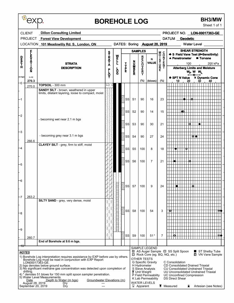
23
15
21
24
18
21
24
3
7 *
16
14
30
27
8
7
9
54
51
S1
S2
S3
S4
S5
S6
S7
S8
S9
TOPSOIL - 300 mm
SANDY SILT - brown, weathered in upperlimits, dilatant layering, loose to compact, moist
- becoming wet near 2.1 m bgs
- becoming grey near 3.1 m bgs
CLAYEY SILT - grey, firm to stiff, moist
SILTY SAND - grey, very dense, moist
End of Borehole at 9.6 m bgs.
SS
SS
SS
SS
SS
SS
SS
SS
SS
90
90
90
90
100
100
100
100
100
270.0
266.6
263.2
260.7
100 200 kPa
1) Borehole Log interpretation requires assistance by EXP before use by others.Borehole Log must be read in conjunction with EXP ReportLON00017363-GE.
2) bgs denotes below ground surface.3) No significant methane gas concentration was detected upon completion of
drilling.4) * denotes 51 blows for 150 mm split spoon sampler penetration.5) Water Level Measurements Date Depth to Water (m bgs) Groundwater Elevations (m) August 28, 2019 Dry ---September 20, 2019 Dry ---
CU Consolidated Undrained TriaxialCD Consolidated Drained Triaxial
K Lab PermeabilityP Field Permeability
Unit Weight
C Consolidation
AS Auger Sample
S Sieve AnalysisH HydrometerG Specific Gravity
OTHER TESTS
Rock Core (eg. BQ, NQ, etc.)ST Shelby TubeSS Split Spoon
SAMPLE LEGEND
Artesian (see Notes)MeasuredApparentWATER LEVELS
DS Direct Shear
VN Vane Sample
UU Unconsolidated Undrained TriaxialUC Unconfined Compression
NOTES
DEPTH
Dynamic ConeSPT N Value
SAMPLES
RECOVERY
S
DESCRIPTION
Torvane
P WW
PROJECT NO.
Field Vane Test (#=Sensitivity)PenetrometerD
EPTH
SHEAR STRENGTH
Water Level
CLIENT
LOCATION
BH3/MWSheet 1 of 1
N
BOREHOLE LOG
MOISTURE
CONTENT
(blows)
( m)~
(%)
Atterberg Limits and MoistureWW
DATUM
Field Vane Test (#=Sensitivity)
Forest View Development
10 20 30 40
P
SHEAR STRENGTH
Penetrometer
270.3
W
Dynamic Cone
L(m bgs)
Geodetic
LON-00017363-GE
DATES: Boring
DESCRIPTION
VALUE
DATES: Boring August 20, 2019
STRATA VALUENUMBER
DATUM
STRATA
LON-00017363-GE
NUMBER
TYPE
August 20, 2019
(%)
TorvaneS
Geodetic
STRATA
PLOT
ELEVATION W
PROJECT
SAMPLES
TYPE
SPT N Value
WELL
LOG
STRATA
PLOT
PROJECT NO.
ELEVATION
L
Atterberg Limits and Moisture
101 Meadowlily Rd. S., London, ON
Dillon Consulting Limited
WELL
LOG
Water Level
0
1
2
3
4
5
6
7
8
9
10
54
51
54
51
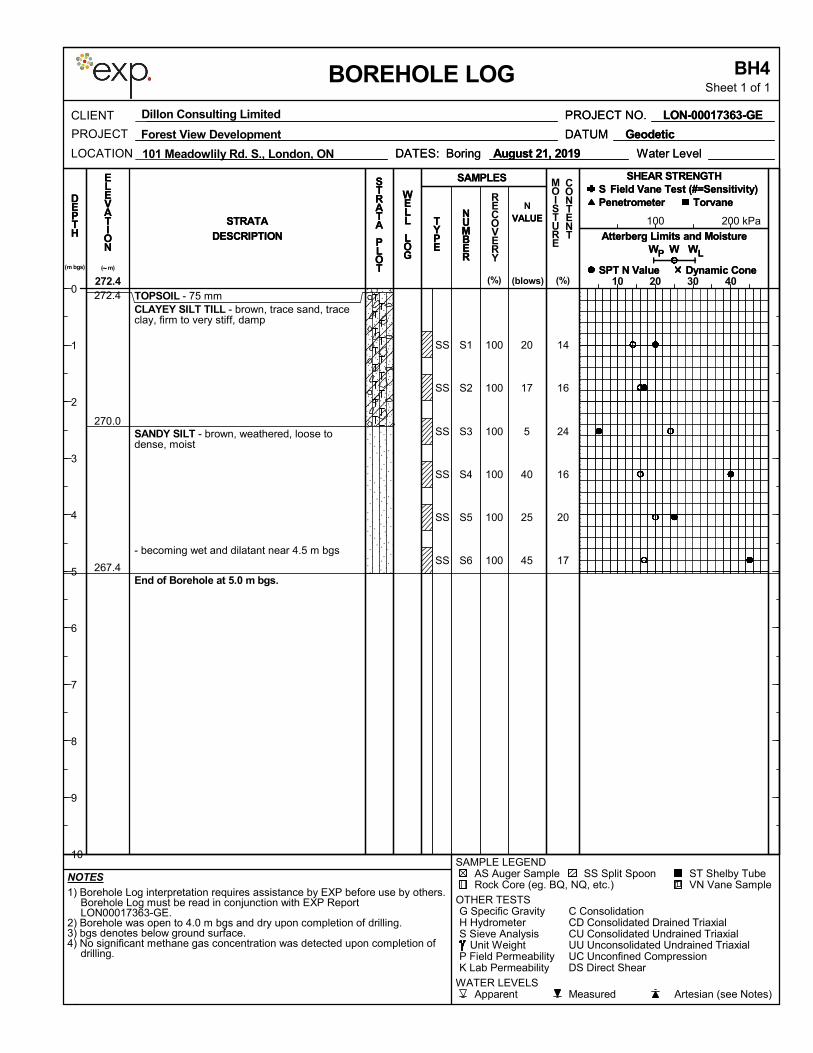
14
16
24
16
20
17
20
17
5
40
25
45
S1
S2
S3
S4
S5
S6
TOPSOIL - 75 mmCLAYEY SILT TILL - brown, trace sand, traceclay, firm to very stiff, damp
SANDY SILT - brown, weathered, loose todense, moist
- becoming wet and dilatant near 4.5 m bgs
End of Borehole at 5.0 m bgs.
SS
SS
SS
SS
SS
SS
100
100
100
100
100
100
272.4
270.0
267.4
100 200 kPa
1) Borehole Log interpretation requires assistance by EXP before use by others.Borehole Log must be read in conjunction with EXP ReportLON00017363-GE.
2) Borehole was open to 4.0 m bgs and dry upon completion of drilling.3) bgs denotes below ground surface.4) No significant methane gas concentration was detected upon completion of
drilling.
CU Consolidated Undrained TriaxialCD Consolidated Drained Triaxial
K Lab PermeabilityP Field Permeability
Unit Weight
C Consolidation
AS Auger Sample
S Sieve AnalysisH HydrometerG Specific Gravity
OTHER TESTS
Rock Core (eg. BQ, NQ, etc.)ST Shelby TubeSS Split Spoon
SAMPLE LEGEND
Artesian (see Notes)MeasuredApparentWATER LEVELS
DS Direct Shear
VN Vane Sample
UU Unconsolidated Undrained TriaxialUC Unconfined Compression
NOTES
DEPTH
Dynamic ConeSPT N Value
SAMPLES
RECOVERY
S
DESCRIPTION
Torvane
P WW
PROJECT NO.
Field Vane Test (#=Sensitivity)PenetrometerD
EPTH
SHEAR STRENGTH
Water Level
CLIENT
LOCATION
BH4Sheet 1 of 1
N
BOREHOLE LOG
MOISTURE
CONTENT
(blows)
( m)~
(%)
Atterberg Limits and MoistureWW
DATUM
Field Vane Test (#=Sensitivity)
Forest View Development
10 20 30 40
P
SHEAR STRENGTH
Penetrometer
272.4
W
Dynamic Cone
L(m bgs)
Geodetic
LON-00017363-GE
DATES: Boring
DESCRIPTION
VALUE
DATES: Boring August 21, 2019
STRATA VALUENUMBER
DATUM
STRATA
LON-00017363-GE
NUMBER
TYPE
August 21, 2019
(%)
TorvaneS
Geodetic
STRATA
PLOT
ELEVATION W
PROJECT
SAMPLES
TYPE
SPT N Value
WELL
LOG
STRATA
PLOT
PROJECT NO.
ELEVATION
L
Atterberg Limits and Moisture
101 Meadowlily Rd. S., London, ON
Dillon Consulting Limited
WELL
LOG
Water Level
0
1
2
3
4
5
6
7
8
9
10
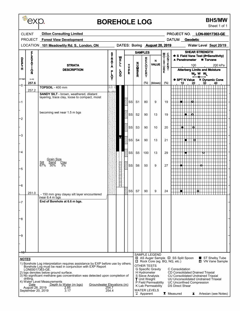
19
19
20
21
29
27
24
9
13
10
13
13
9
9
S1
S2
S3
S4
S5
S6
S7
TOPSOIL - 400 mm
SANDY SILT - brown, weathered, dilatantlayering, trace clay, loose to compact, moist
becoming wet near 1.5 m bgs
Grain SizeSilt Sand Clay67% 30% 3%
- 150 mm grey clayey silt layer encounterednear 6.4 m bgsEnd of Borehole at 6.6 m bgs.
SS
SS
SS
SS
SS
SS
SS
80
90
90
90
100
50
90
257.2
251.0
100 200 kPa
1) Borehole Log interpretation requires assistance by EXP before use by others.Borehole Log must be read in conjunction with EXP ReportLON00017363-GE.
2) bgs denotes below ground surface.3) No significant methane gas concentration was detected upon completion of
drilling.4) Water Level Measurements Date Depth to Water (m bgs) Groundwater Elevations (m) August 28, 2019 2.85 254.7September 20, 2019 3.17 254.4
CU Consolidated Undrained TriaxialCD Consolidated Drained Triaxial
K Lab PermeabilityP Field Permeability
Unit Weight
C Consolidation
AS Auger Sample
S Sieve AnalysisH HydrometerG Specific Gravity
OTHER TESTS
Rock Core (eg. BQ, NQ, etc.)ST Shelby TubeSS Split Spoon
SAMPLE LEGEND
Artesian (see Notes)MeasuredApparentWATER LEVELS
DS Direct Shear
VN Vane Sample
UU Unconsolidated Undrained TriaxialUC Unconfined Compression
NOTES
DEPTH
Dynamic ConeSPT N Value
SAMPLES
RECOVERY
S
DESCRIPTION
Torvane
P WW
PROJECT NO.
Field Vane Test (#=Sensitivity)PenetrometerD
EPTH
SHEAR STRENGTH
Water Level
CLIENT
LOCATION
BH5/MWSheet 1 of 1
N
BOREHOLE LOG
MOISTURE
CONTENT
(blows)
( m)~
(%)
Atterberg Limits and MoistureWW
DATUM
Field Vane Test (#=Sensitivity)
Forest View Development
10 20 30 40
P
SHEAR STRENGTH
Penetrometer
257.6
W
Dynamic Cone
L(m bgs)
Geodetic
LON-00017363-GE
DATES: Boring
DESCRIPTION
VALUE
DATES: Boring August 20, 2019 Sept 20/19
STRATA VALUENUMBER
DATUM
STRATA
LON-00017363-GE
NUMBER
TYPE
August 20, 2019
(%)
TorvaneS
Geodetic
STRATA
PLOT
ELEVATION W
PROJECT
SAMPLES
TYPE
SPT N Value
WELL
LOG
STRATA
PLOT
PROJECT NO.
ELEVATION
L
Atterberg Limits and Moisture
101 Meadowlily Rd. S., London, ON
Dillon Consulting Limited
WELL
LOG
Water Level
0
1
2
3
4
5
6
7
8
9
10
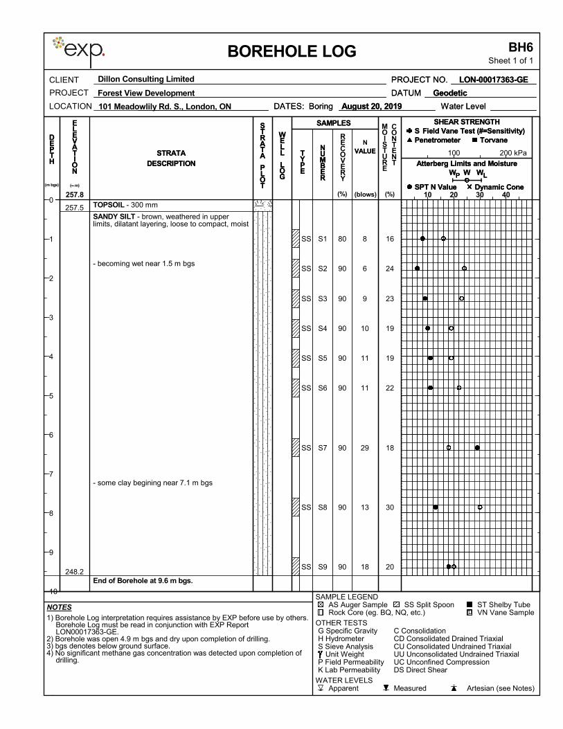
16
24
23
19
19
22
18
30
20
8
6
9
10
11
11
29
13
18
S1
S2
S3
S4
S5
S6
S7
S8
S9
TOPSOIL - 300 mm
SANDY SILT - brown, weathered in upperlimits, dilatant layering, loose to compact, moist
- becoming wet near 1.5 m bgs
- some clay begining near 7.1 m bgs
End of Borehole at 9.6 m bgs.
SS
SS
SS
SS
SS
SS
SS
SS
SS
80
90
90
90
90
90
90
90
90
257.5
248.2
100 200 kPa
1) Borehole Log interpretation requires assistance by EXP before use by others.Borehole Log must be read in conjunction with EXP ReportLON00017363-GE.
2) Borehole was open 4.9 m bgs and dry upon completion of drilling.3) bgs denotes below ground surface.4) No significant methane gas concentration was detected upon completion of
drilling.
CU Consolidated Undrained TriaxialCD Consolidated Drained Triaxial
K Lab PermeabilityP Field Permeability
Unit Weight
C Consolidation
AS Auger Sample
S Sieve AnalysisH HydrometerG Specific Gravity
OTHER TESTS
Rock Core (eg. BQ, NQ, etc.)ST Shelby TubeSS Split Spoon
SAMPLE LEGEND
Artesian (see Notes)MeasuredApparentWATER LEVELS
DS Direct Shear
VN Vane Sample
UU Unconsolidated Undrained TriaxialUC Unconfined Compression
NOTES
DEPTH
Dynamic ConeSPT N Value
SAMPLES
RECOVERY
S
DESCRIPTION
Torvane
P WW
PROJECT NO.
Field Vane Test (#=Sensitivity)PenetrometerD
EPTH
SHEAR STRENGTH
Water Level
CLIENT
LOCATION
BH6Sheet 1 of 1
N
BOREHOLE LOG
MOISTURE
CONTENT
(blows)
( m)~
(%)
Atterberg Limits and MoistureWW
DATUM
Field Vane Test (#=Sensitivity)
Forest View Development
10 20 30 40
P
SHEAR STRENGTH
Penetrometer
257.8
W
Dynamic Cone
L(m bgs)
Geodetic
LON-00017363-GE
DATES: Boring
DESCRIPTION
VALUE
DATES: Boring August 20, 2019
STRATA VALUENUMBER
DATUM
STRATA
LON-00017363-GE
NUMBER
TYPE
August 20, 2019
(%)
TorvaneS
Geodetic
STRATA
PLOT
ELEVATION W
PROJECT
SAMPLES
TYPE
SPT N Value
WELL
LOG
STRATA
PLOT
PROJECT NO.
ELEVATION
L
Atterberg Limits and Moisture
101 Meadowlily Rd. S., London, ON
Dillon Consulting Limited
WELL
LOG
Water Level
0
1
2
3
4
5
6
7
8
9
10

20
22
27
20
21
19
25
9
11
9
16
14
10
12
S1
S2
S3
S4
S5
S6
S7
TOPSOIL - 200 mmSILTY SAND - brown, weathered in upperlimits, dilatant layering, loose to compact, moist
- becoming wet near 1.5 m bgs
- thin clayey silt layering encountered near 3.8m bgs
End of Borehole at 6.6 m bgs.
SS
SS
SS
SS
SS
SS
SS
80
90
90
90
90
90
100
254.5
248.1
100 200 kPa
1) Borehole Log interpretation requires assistance by EXP before use by others.Borehole Log must be read in conjunction with EXP ReportLON00017363-GE.
2) bgs denotes below ground surface.3) No significant methane gas concentration was detected upon completion of
drilling.4) Water Level Measurements Date Depth to Water (m bgs) Groundwater Elevations (m) August 28, 2019 3.34 251.4September 20, 2019 3.47 251.2
CU Consolidated Undrained TriaxialCD Consolidated Drained Triaxial
K Lab PermeabilityP Field Permeability
Unit Weight
C Consolidation
AS Auger Sample
S Sieve AnalysisH HydrometerG Specific Gravity
OTHER TESTS
Rock Core (eg. BQ, NQ, etc.)ST Shelby TubeSS Split Spoon
SAMPLE LEGEND
Artesian (see Notes)MeasuredApparentWATER LEVELS
DS Direct Shear
VN Vane Sample
UU Unconsolidated Undrained TriaxialUC Unconfined Compression
NOTES
DEPTH
Dynamic ConeSPT N Value
SAMPLES
RECOVERY
S
DESCRIPTION
Torvane
P WW
PROJECT NO.
Field Vane Test (#=Sensitivity)PenetrometerD
EPTH
SHEAR STRENGTH
Water Level
CLIENT
LOCATION
BH7/MWSheet 1 of 1
N
BOREHOLE LOG
MOISTURE
CONTENT
(blows)
( m)~
(%)
Atterberg Limits and MoistureWW
DATUM
Field Vane Test (#=Sensitivity)
Forest View Development
10 20 30 40
P
SHEAR STRENGTH
Penetrometer
254.7
W
Dynamic Cone
L(m bgs)
Geodetic
LON-00017363-GE
DATES: Boring
DESCRIPTION
VALUE
DATES: Boring August 20, 2019 Sept 20/19
STRATA VALUENUMBER
DATUM
STRATA
LON-00017363-GE
NUMBER
TYPE
August 20, 2019
(%)
TorvaneS
Geodetic
STRATA
PLOT
ELEVATION W
PROJECT
SAMPLES
TYPE
SPT N Value
WELL
LOG
STRATA
PLOT
PROJECT NO.
ELEVATION
L
Atterberg Limits and Moisture
101 Meadowlily Rd. S., London, ON
Dillon Consulting Limited
WELL
LOG
Water Level
0
1
2
3
4
5
6
7
8
9
10
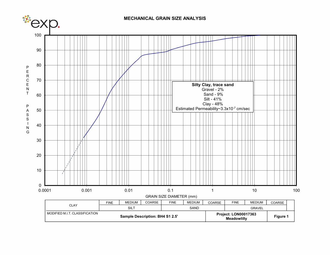
MECHANICAL GRAIN SIZE ANALYSIS
0
10
20
30
40
50
60
70
80
90
100
0.0001 0.001 0.01 0.1 1 10 100
GRAIN SIZE DIAMETER (mm)
PERCENT
PASSI
NG
SILT SAND GRAVEL
FINE MEDIUM COARSE FINE MEDIUM COARSE FINE MEDIUM COARSECLAY
MODIFIED M.I.T. CLASSIFICATIONSample Description: BH4 S1 2.5' Figure 1
Project: LON00017363Meadowlilly
Silty Clay, trace sandGravel - 2%Sand - 9% Silt - 41%
Clay - 48% Estimated Permeability~3.3x10⁻⁷ cm/sec
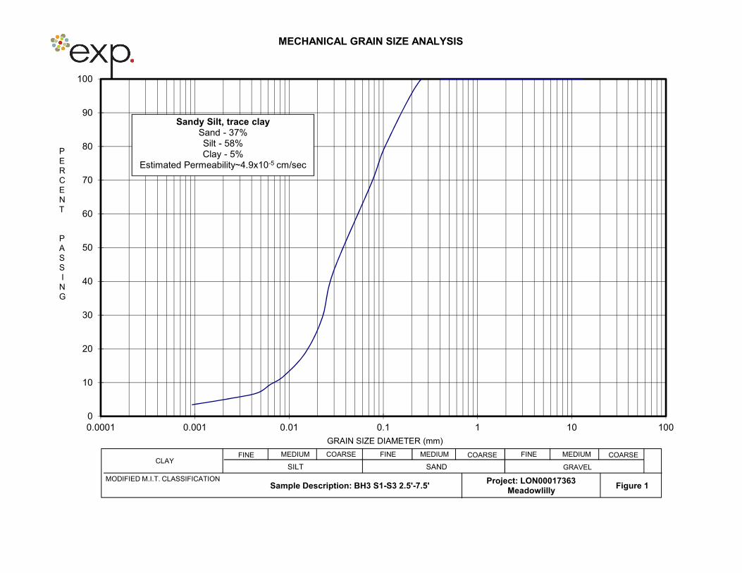
MECHANICAL GRAIN SIZE ANALYSIS
0
10
20
30
40
50
60
70
80
90
100
0.0001 0.001 0.01 0.1 1 10 100
GRAIN SIZE DIAMETER (mm)
PERCENT
PASSI
NG
SILT SAND GRAVEL
FINE MEDIUM COARSE FINE MEDIUM COARSE FINE MEDIUM COARSECLAY
MODIFIED M.I.T. CLASSIFICATIONSample Description: BH3 S1-S3 2.5'-7.5' Figure 1
Project: LON00017363Meadowlilly
Sandy Silt, trace claySand - 37% Silt - 58% Clay - 5%
Estimated Permeability~4.9x10⁻⁵ cm/sec
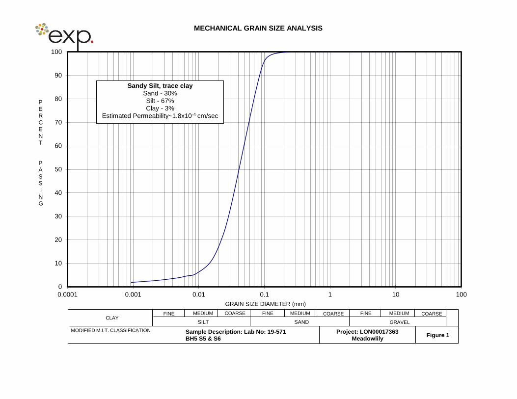
MECHANICAL GRAIN SIZE ANALYSIS
0
10
20
30
40
50
60
70
80
90
100
0.0001 0.001 0.01 0.1 1 10 100
GRAIN SIZE DIAMETER (mm)
PERCENT
PASSI
NG
SILT SAND GRAVEL
FINE MEDIUM COARSE FINE MEDIUM COARSE FINE MEDIUM COARSECLAY
MODIFIED M.I.T. CLASSIFICATION Sample Description: Lab No: 19-571BH5 S5 & S6
Figure 1Project: LON00017363
Meadowlily
Sandy Silt, trace claySand - 30% Silt - 67% Clay - 3%
Estimated Permeability~1.8x10⁻⁴ cm/sec
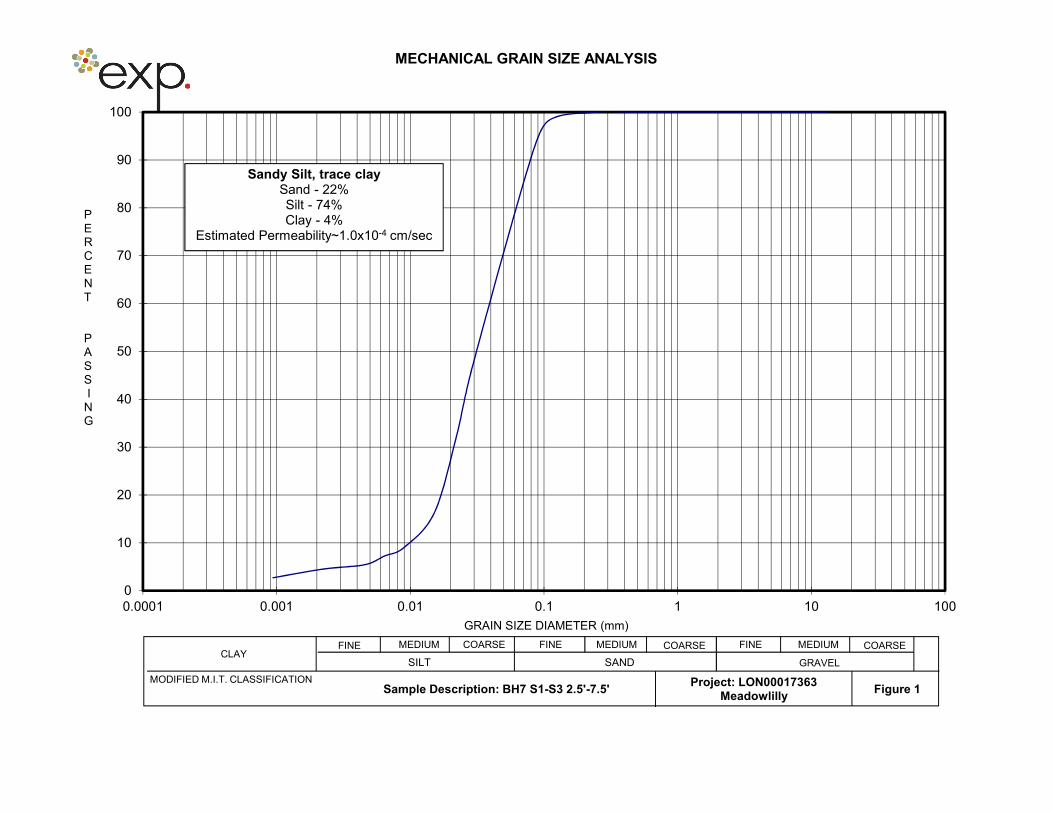
MECHANICAL GRAIN SIZE ANALYSIS
0
10
20
30
40
50
60
70
80
90
100
0.0001 0.001 0.01 0.1 1 10 100
GRAIN SIZE DIAMETER (mm)
PERCENT
PASSI
NG
SILT SAND GRAVEL
FINE MEDIUM COARSE FINE MEDIUM COARSE FINE MEDIUM COARSECLAY
MODIFIED M.I.T. CLASSIFICATIONSample Description: BH7 S1-S3 2.5'-7.5' Figure 1
Project: LON00017363Meadowlilly
Sandy Silt, trace claySand - 22% Silt - 74% Clay - 4%
Estimated Permeability~1.0x10⁻⁴ cm/sec

15701 Robin’s Hill Road | London, Ontario | Canada
t: +1.519.963.3000 | f: +1.519.963.1152 | exp.com
Appendix B – Inspecting and Testing Schedule
EXP Services Inc. Project Name: Applewood Subdivision, Block 1
Project Location: 660 Sunningdale Rd. E., London, ON
Project Number: LON-00017354-GE
Date: September 2019
40
Earth and Environmental Division - Geotechnical
INSPECTION & TESTING SCHEDULE
The following program outlines suggested minimum testing requirements during backfilling of service trenches and construction of pavements. In adverse weather conditions (wet/freezing), increased testing will be required. The testing frequencies are general requirements and may be adjusted at the discretion of the engineer based on test results and prevailing construction conditions.
I TRENCH BACKFILL ZONE A - one in situ density test per 100 cubic meters or 50 linear
metres of trench whichever is less - one laboratory grain size and Proctor density test per 50
density tests or 4000 cubic metres or on change of material (source, visual)
ZONE A1 - one in situ density test per 75 cubic metres of material or 25 linear metres of each lift of fill
- one laboratory grain size and Proctor density test per each 50 density tests or 4000 cubic metres of material placed or as directed by the engineer
ZONES B & C - one in situ density test per 150 cubic metres of material or 50 linear metres or each lift whichever is less
- one laboratory grain size and Proctor density test per 50 density tests or 4000 cubic metres of material placed or as directed by the engineer
II PAVEMENT MATERIALS GRANULAR SUBBASE - one in situ density test per 50 linear metres of road - one laboratory grain size and standard Proctor test per 50
density tests or 4000 cubic metres or each change of material (visual, source), as determined by the engineer
GRANULAR BASE - one in situ density test per 50 linear metres of road - one laboratory grain size and Proctor per 50 density tests or
8000 cubic metres or change in material (visual, source), as determined by the engineer
- Benkelman beam testing at 10 metre intervals per lane, after final grading and compaction. Asphaltic concrete should not be placed until rebound criteria have been satisfied.
ASPHALTIC CONCRETE - one in situ density test per 25 linear metres of roadway - one complete Marshall Compliance test including stability
flow, etc. for each mix type to check mix acceptability. One extraction and gradation test per each day of paving to be compared to job mix formula
NOTES: Where testing indicates inadequate compaction, additional fill should not be placed until the area is recompacted and retested at the discretion of the engineer.

15701 Robin’s Hill Road | London, Ontario | Canada
t: +1.519.963.3000 | f: +1.519.963.1152 | exp.com
Appendix C – Limitations and Use of Report

EXP Services Inc. Project Name: Applewood Subdivision, Block 1
Project Location: 660 Sunningdale Rd. E., London, ON
Project Number: LON-00017354-GE
Date: September 2019
42
Earth and Environmental Division - Geotechnical
LIMITATIONS AND USE OF REPORT
BASIS OF REPORT
This report (“Report”) is based on site conditions known or inferred by the geotechnical investigation undertaken as
of the date of the Report. Should changes occur which potentially impact the geotechnical condition of the site, or if
construction is implemented more than one year following the date of the Report, the recommendations of EXP may
require re-evaluation.
The Report is provided solely for the guidance of design engineers and on the assumption that the design will be in
accordance with applicable codes and standards. Any changes in the design features which potentially impact the
geotechnical analyses or issues concerning the geotechnical aspects of applicable codes and standards will
necessitate a review of the design by EXP. Additional field work and reporting may also be required.
Where applicable, recommended field services are the minimum necessary to ascertain that construction is being
carried out in general conformity with building code guidelines, generally accepted practices and EXP’s
recommendations. Any reduction in the level of services recommended will result in EXP providing qualified opinions
regarding the adequacy of the work. EXP can assist design professionals or contractors retained by the Client to
review applicable plans, drawings, and specifications as they relate to the Report or to conduct field reviews during
construction.
Contractors contemplating work on the site are responsible for conducting an independent investigation and
interpretation of the borehole results contained in the Report. The number of boreholes necessary to determine the
localized underground conditions as they impact construction costs, techniques, sequencing, equipment and
scheduling may be greater than those carried out for the purpose of the Report.
Classification and identification of soils, rocks, geological units, contaminant materials, building envelopment
assessments, and engineering estimates are based on investigations performed in accordance with the standard of
care set out below and require the exercise of judgment. As a result, even comprehensive sampling and testing
programs implemented with the appropriate equipment by experienced personnel may fail to locate some conditions.
All investigations or building envelope descriptions involve an inherent risk that some conditions will not be detected.
All documents or records summarizing investigations are based on assumptions of what exists between the actual
points sampled. Actual conditions may vary significantly between the points investigated. Some conditions are
subject to change over time. The Report presents the conditions at the sampled points at the time of sampling.
Where special concerns exist, or the Client has special considerations or requirements, these should be disclosed to
EXP to allow for additional or special investigations to be undertaken not otherwise within the scope of investigation
conducted for the purpose of the Report.
EXP Services Inc. Project Name: Applewood Subdivision, Block 1
Project Location: 660 Sunningdale Rd. E., London, ON
Project Number: LON-00017354-GE
Date: September 2019
43
Earth and Environmental Division - Geotechnical
RELIANCE ON INFORMATION PROVIDED
The evaluation and conclusions contained in the Report are based on conditions in evidence at the time of site
inspections and information provided to EXP by the Client and others. The Report has been prepared for the specific
site, development, building, design or building assessment objectives and purpose as communicated by the Client.
EXP has relied in good faith upon such representations, information and instructions and accepts no responsibility
for any deficiency, misstatement or inaccuracy contained in the Report as a result of any misstatements, omissions,
misrepresentation or fraudulent acts of persons providing information. Unless specifically stated otherwise, the
applicability and reliability of the findings, recommendations, suggestions or opinions expressed in the Report are
only valid to the extent that there has been no material alteration to or variation from any of the information
provided to EXP.
STANDARD OF CARE
The Report has been prepared in a manner consistent with the degree of care and skill exercised by engineering
consultants currently practicing under similar circumstances and locale. No other warranty, expressed or implied, is
made. Unless specifically stated otherwise, the Report does not contain environmental consulting advice.
COMPLETE REPORT
All documents, records, data and files, whether electronic or otherwise, generated as part of this assignment form
part of the Report. This material includes, but is not limited to, the terms of reference given to EXP by its client
(“Client”), communications between EXP and the Client, other reports, proposals or documents prepared by EXP for
the Client in connection with the site described in the Report. In order to properly understand the suggestions,
recommendations and opinions expressed in the Report, reference must be made to the Report in its entirety. EXP
is not responsible for use by any party of portions of the Report.
USE OF REPORT
The information and opinions expressed in the Report, or any document forming part of the Report, are for the sole
benefit of the Client. No other party may use or rely upon the Report in whole or in part without the written consent
of EXP. Any use of the Report, or any portion of the Report, by a third party are the sole responsibility of such third
party. EXP is not responsible for damages suffered by any third party resulting from unauthorised use of the Report.
REPORT FORMAT
Where EXP has submitted both electronic file and a hard copy of the Report, or any document forming part of the
Report, only the signed and sealed hard copy shall be the original documents for record and working purposes. In
the event of a dispute or discrepancy, the hard copy shall govern. Electronic files transmitted by EXP have utilize
specific software and hardware systems. EXP makes no representation about the compatibility of these files with the
Client’s current or future software and hardware systems. Regardless of format, the documents described herein are
EXP’s instruments of professional service and shall not be altered without the written consent of EXP.

EXP Services Inc. Project Name: Applewood Subdivision, Block 1
Project Location: 660 Sunningdale Rd. E., London, ON
Project Number: LON-00017354-GE
Date: September 2019
44
Earth and Environmental Division - Geotechnical
Legal Notification
This report was prepared by EXP Services Inc. for the exclusive use of Dillon Consulting Limited and may not be
reproduced in whole or in part, or used or relied upon in whole or in part by any party other than Dillon Consulting
Limited for any purpose whatsoever without the express permission of Dillon Consulting Limited in writing.
Any use which a third party makes of this report, or any reliance on or decisions to be made based on it, are the
responsibility of such third parties. EXP Services Inc. accepts no responsibility for damages, if any, suffered by any
third party as a result of decisions made or actions taken based on this project.