nicholasvlachopoulos.canicholasvlachopoulos.ca/.../2014_-_journal_-_gege_-_nomenclature.pdf98...
36
1 23 Geotechnical and Geological Engineering An International Journal ISSN 0960-3182 Volume 32 Number 1 Geotech Geol Eng (2014) 32:97-130 DOI 10.1007/s10706-013-9697-4 Umbrella Arch Nomenclature and Selection Methodology for Temporary Support Systems for the Design and Construction of Tunnels Jeffrey Oke, Nicholas Vlachopoulos & Vassilis Marinos
Transcript of nicholasvlachopoulos.canicholasvlachopoulos.ca/.../2014_-_journal_-_gege_-_nomenclature.pdf98...
1 23
Geotechnical and GeologicalEngineeringAn International Journal ISSN 0960-3182Volume 32Number 1 Geotech Geol Eng (2014) 32:97-130DOI 10.1007/s10706-013-9697-4
Umbrella Arch Nomenclature and SelectionMethodology for Temporary SupportSystems for the Design and Construction ofTunnels
Jeffrey Oke, Nicholas Vlachopoulos &Vassilis Marinos

1 23
Your article is protected by copyright and all
rights are held exclusively by Her Majesty the
Queen in Right of Canada. This e-offprint is
for personal use only and shall not be self-
archived in electronic repositories. If you wish
to self-archive your article, please use the
accepted manuscript version for posting on
your own website. You may further deposit
the accepted manuscript version in any
repository, provided it is only made publicly
available 12 months after official publication
or later and provided acknowledgement is
given to the original source of publication
and a link is inserted to the published article
on Springer's website. The link must be
accompanied by the following text: "The final
publication is available at link.springer.com”.

ORIGINAL PAPER
Umbrella Arch Nomenclature and Selection Methodologyfor Temporary Support Systems for the Designand Construction of Tunnels
Jeffrey Oke • Nicholas Vlachopoulos •
Vassilis Marinos
Received: 26 April 2013 / Accepted: 10 September 2013 / Published online: 27 September 2013
� Her Majesty the Queen in Right of Canada 2013
Abstract This paper argues that there is a require-
ment for standardized nomenclature and a selection
methodology for a particular class of temporary
support. The authors have chosen the term Umbrella
Arch (UA) to define the method of support that acts as
pre-support that is installed during the first pass of the
excavation around and above the crown of the tunnel
face. The UA supports the rock mass and the tunnel
face predominately by transferring loading longitudi-
nally through the interaction of the support and
surrounding ground condition. There are three cate-
gories of UA. Categorization depends on the type of
support element used. These elements include: (1)
Spiles; (2) Forepoles; and (3) Grouted. These catego-
ries can be further divided into 11 sub-categories
quantified by the amount of grout utilized in the
installation. The sub-categories are justified by the
employment of each sub-category within a support
selection methodology for an UA; this was created by
the authors based on experience and through a
comprehensive literature search that included pub-
lished papers as well as design reports. The collection
of publications has resulted in 141 permutations of
different temporary tunnel support in varying weak
and difficult geological condition. The UA support
selection methodology was created to aid tunnel
designers in these conditions with the basic concepts
for the appropriate selection process for an UA.
Furthermore, the authors quantified the support selec-
tion methodology through the employment of other
pre-existing design charts and empirical evidence to
create a new design tool, the UA selection chart.
Overall, this paper hopes to achieve the creation of an
international standard with respect to UA and UA
support element nomenclature and a better under-
standing for the selection of a particular UA sub-
category.
Keywords Umbrella Arch � Forepole � Spile �Grout � Tunnel behaviour chart �Weak rock �Temporary rock support and tunnelling
1 Introduction
Varying geological conditions can lead to complica-
tions with respect to underground works and tunnel-
ling excavations. Weak rock masses (or granular
material with low cohesion) that are encountered
during excavation (whether foreseen or unexpected)
can require additional and ingenious means of tem-
porary support measure to prevent failure of the
J. Oke � N. Vlachopoulos (&)
GeoEngineering Centre, Queen’s-RMC, Kingston, ON,
Canada
e-mail: [email protected]
V. Marinos
Faculty of Sciences, School of Geology, Aristotle
University of Thessaloniki, Thessaloniki, Greece
123
Geotech Geol Eng (2014) 32:97–130
DOI 10.1007/s10706-013-9697-4
Author's personal copy
ground. Pre-support (Sadaghiani and Dadizadeh 2010)
(pre-confinement (Lunardi 2008), auxiliary method
(Kimura et al. 2005), and pre-improvement (Song
et al. 2006), is an additional means of initial,
temporary support utilized in tunnel construction
when there is a requirement for support ahead of the
tunnel face. Pre-support is divided into two funda-
mental methods: (a) face support and, (b) support
added in the vicinity of the crown above the face
(Fig. 1, yellow region). While the debate between
these two pre-support methods has generated interest
in the tunnelling community, identification of the
superior method is outside the scope of this paper. This
paper focuses on the pre-support in the locality above
the face at the crown of a tunnel excavation (category
b) strictly during the first pass of the excavation (or at
the portal). Pre-support installed from the surface,
from adjacent excavations, and within or around a
pilot tunnel are outside the scope of this paper.
Additionally, the pre-support schemes investigated
provide reinforcement by strengthening the surround-
ing geological material through the interaction
between the support elements installed and the soil/
rock mass. An in-depth literature review of relevant
methods of crown support reveals a complicated and
confusing use of terminology that describe relatively
the same fundamental support types by function. The
authors have accepted the general term of the tempo-
rary support arrangement (category b) as an Umbrella
Arch (UA) (Appendix 1) that encompass the following
exhaustive list of support elements within the termi-
nology cited in literature: Forepole (Hoek 2007), pipe
roofing (Gamsjager and Scholz 2009), pipe roof
support (Volkmann and Schubert 2007), pipe roof
umbrella, steel pipe umbrella, UA method (Ocak
2008), umbrella vault (Leca and Barry 2007) long span
steel pipe fore-piling (Miura 2003), steel pile canopy
(Gibbs et al. 2007), sub-horizontal jet-grout columns
(Coulter and Martin 2006) canopy technique: jet-
columns (Croce et al. 2004), and Spiles (Sp) (Trinh
et al. 2007; Hoek 2007). Further investigation reveals
that for each of the previously listed temporary support
elements there are noted differences in their use,
application and/or interaction with the soil/rock mass
(i.e. in terms of stiffness and grout). The UA definition
alone does not address the usage and functional
differences of the cited terminologies. Additional
categories are warranted to further filter the terminol-
ogy. However, selected terminologies commonly used
in literature are loosely defined, resulting in conflicting
categories (further explained in subsequent sections).
Therefore, a standardized nomenclature of support
types is warranted in order to ensure that tunnelling
engineers and relevant practitioners communicate
effectively and adhere to an accepted universal
standard. These categories and sub-categories are
presented herein as a standardized nomenclature for
these support types.
To further organize and differentiate between the
various temporary support sub-categories that exist
within the standardized nomenclature presented
herein, the authors also introduce a support selection
methodology for an UA based on geological features,
anticipated/observed failure mechanisms, impact of
water presence, as well as relevant, in situ consider-
ations. This support selection methodology will aid the
tunnel design engineer selection of the type of UA sub-
categories under certain conditions. This support
methodology has been further quantified within the
herein, developed Umbrella Arch Selection Chart
(UASC) that is substantiated primarily by relevant UA
applications cited in literature data, and with other
design charts. As such, the UASC (and the antecedent
design methodology) that has been developed in this
paper has been empirically and numerically substan-
tiated; empirically verified using 141 cited publica-
tions (and design reports) of tunnels that utilized such
support schemes in various geological conditions and
numerically supported through additional literature
review that captures the improvement trends, from
numerical analysis, of subsidence under different
geological conditions and UA support systems.
2 Background
The design parameters associated with the support
elements consist primarily of: length (L), angle of
installation, overlap of successive UAs, spacing
between support elements, diameter of support ele-
ments (Fig. 1), and grouting pressure. Selected
researchers (Song et al. 2006) have attempted to
optimize selected design parameters of UAs. How-
ever, without a clear determination of when to utilize a
certain support type within certain ground conditions,
optimization of temporary support element arrange-
ments is not possible. As such, investigating pre-
existing UA support systems employed in tunnelling
98 Geotech Geol Eng (2014) 32:97–130
123
Author's personal copy

projects around the globe in different geological
conditions has provided very real insight into the
relevance of a particular support element for certain
conditions. In addition, the investigation found that the
nomenclature of the support elements utilized in
tunnelling projects around the globe that are of similar
function and have similar design parameters must be
standardized. An example of an attempt at optimiza-
tion of support elements without a standardized or
clear definition can be seen within Song et al. (2006).
Song et al. (2006) conducted a parametric analysis by
varying the design parameters of UA support ele-
ments. The parametric analysis consisted of (but was
not limited to) varying the diameter of the tunnel and
the length of the support elements from 10–30 to
6–18 m respectively. Even though the parametric
analysis captured the positive trends, with respect to
convergence, of an increase in the length of the
support, Song et al. (2006) did not address the
condition of a support length (L) less than the height
of the tunnel excavation (He). Many researchers have
distinguished the two types of support element
lengths: a length smaller than the tunnel excavation
height (L \ He); and a support element length larger
than the excavation height (L [ He) (Miura 2003;
Peila and Pelizza 2003; Volkmann and Schubert 2006;
Leca and Barry 2007; Wittke et al. 2006; Tuncdemir
et al. 2012; Fang et al. 2012). A comparison of support
elements (Table 1) illustrates the existence of two
types of supports that exist in literature based on the
work of Tuncdemir et al. (2012) and Wittke et al.
(2006).
It is evident that the support types and dimensions
included in Table 1 cause some confusion in terms of
naming supports. A clear design parameter that
divides both of the referenced authors’ definitions in
Table 1 is the support length. In general terms, what
Fig. 1 Umbrella Arch design parameters, illustration of a
Forepole confined Umbrella Arch. The yellow shaded region
defines the applicable zone of where the Umbrella Arch is
installed (category b). The other pre-support (category a) is
installed within the unexcavated tunnel zone only. He height of
excavation
Table 1 Example of conflicting nomenclature of Umbrella
Arch support elements and design parameters
Typical reference
excavation type: metro
tunnel (He = *6.87 m)
(Tuncdemir et al. 2012)
Typical reference
excavation type:
highway tunnel
(He = *8.85–*14 m)
(Wittke et al. 2006)
L \ He Forepole Spiles
Length 3–4 m (sometimes 5 m) 3–6 m (12 m if grout
injected)
Angle 5�–10� 5�–15�Overlap 1/4–3/4 of length
(generally 1/2)
0.8–1.2 m
Spacing No reference Max 30 cm
Size 32–38.1 mm 25–28 mm
L [ He Umbrella Arch Pipe umbrella
Length 9–16 m 15–30 m
Angle 6�–8� -5�Overlap 1/4–3/4 of length
(generally �)
Min 3 m
Thickness *3.65 mm 8–25 mm
Spacing *30 cm 30–50 cm
Size 114 mm 76–200 mm
He height of excavation
* Not generalized values, values from selected authors published
case studies
Geotech Geol Eng (2014) 32:97–130 99
123
Author's personal copy

Tuncdemir et al. (2012) define as a Forepole, Wittke
et al. (2006) name as a Spile. Further, for similar
functions, the cited authors use dissimilar terms for
similar support functions; one uses UA while the other
uses Pipe Umbrella. The smaller supports (Forepole
and Sp) have a length of support smaller than typical
excavation height referenced. Similarly the larger
supports (UA and Pipe Umbrella) have a length of
support greater than the typical excavation height
referenced. Furthermore, a comparison of the other
design parameters of Table 1, Forepoles (Fp) and Sp
are generally installed at greater angles, smaller size,
and with closer spacing than the larger UA and Pipe
Umbrella elements. These differences exist because
the selection of shorter support elements is usually
based on structural (geological) failure type and/or
availability of proper installation equipment. The
selection of longer support is commonly based on
preventing complete failure of the tunnel face, or to
minimize the convergence of the tunnel in order to
minimize surface settlements. Therefore, the failure
mechanism and the risk of convergence will dictate the
appropriate composition of the UA support elements.
As previously stated, standardized nomenclature
is required, with respect to the use of the appro-
priate support elements as part of the UA, in order
to properly address a variety or expected geological
failure modes. This standardization will serve to
regulate terminology and prevent conflicting tech-
nical terms associated with temporary support
elements that constitute an UA. An example of
such conflicting terminology is evident in the works
of Hoek (2007) and Tuncdemir et al. (2012). The
respective publications utilize the same terminology
in order to define two, separate support arrange-
ments. Hoek (2007) refers to the smaller supports
as Sp, and the larger supports as Fp, while
Tuncdemir et al. (2012) refer to the smaller
supports as Fp, and the larger supports as an UA.
Hoek (2007) states that the length of a Forepole is
typically 12 m, while Tuncdemir et al. (2012) state
the typical length is 3–4 m. The discrepancies that
currently exist with regards to the definitions of
such support elements may, potentially (yet criti-
cally) not perform with the same mechanical
behaviour of the support element-rock mass/soil
interaction (i.e. support element choice has a range
of length and stiffness that affect its performance
and mechanical behaviour). Hence, without a
requirement for a standardization of terminology,
conflict of terms could arise which could lead to
confusion when communicated amongst engineers
and when handled by construction project personnel
within the context of international collaborations.
The resulting lack of clarity could also lead to
wasted resources (mainly cost) for both the con-
tractors and their clients.
Other publications have attempted to rectify the
other related discrepancies through a classification
based on the differences and similarities of certain
support schemes. An example of such a classification
can be found within the works of Peila and Pelizza
(2003) as summarized in Table 2. Peila and Pelizza
(2003) listed the most common ground reinforcement
techniques that provide improvement, reinforcement,
pre-support, and drainage past the tunnel face (i.e. into
the rock mass in front of the tunnel face). However,
Table 2 only lists the division of support elements
with respect to the generalized geological material
conditions. Factors involving impact at the subsi-
dence, water conditions, and type of failure conditions
have not been taken into consideration; key mecha-
nisms that must be taken into account at the design
stage. The findings of this paper further expands the
classification of interventions a–c (in Table 2) of Peila
and Pelizza (2003) in isolation and/or in combination
with each other. The other methods cited in Table 2
(i.e. d–h) have not been investigated as their tech-
niques are not a first pass construction-type system
and/or do not take into consideration strengthening
and interaction between the support installed and the
surrounding geological material. Additional methods
exist that have been classified as pre-support but are
not included within Table 2. These methods have been
employed in tunnelling works in difficult terrain and
are often compared to an UA method. However some
of these methods fall outside the scope of an UA, they
are included herein in order to distinguish and further
clarify the definition of the UA as defined by the
authors (Appendix 1). For clarification, the definition
of the UA, as defined by the authors, is a pre-support
method that is installed during the first pass of
excavation from within the tunnel, above and around
the crown of the tunnel face, that reinforces through
the interaction of support and the rock mass/soil. The
three categories and ensuing 11 sub-categories of an
UA will be explained in subsequent sections and
summarized in Appendix 1.
100 Geotech Geol Eng (2014) 32:97–130
123
Author's personal copy

2.1 Other Pre-support Methods
There is an abundance of varying methods of tempo-
rary support about the crown that do not fall under the
definition of the UA (Appendix 1) (Schumacher and
Kim 2013, Sadaghiani and Dadizadeh 2010; Leca and
Barry 2007). Selected authors have erroneously com-
pared cited support methods to an UA or have
suggested that these methods belong within the within
the classification of an UA. Examples resulting in such
possible misclassifications are: the Concrete Arch Pre-
Supporting System (CAPS) and pre-vault methods.
These methods are the focus of the sub-sections below.
2.1.1 Concrete Arch Pre-supporting System (CAPS)
CAPS is the process of creating side audits of pre-
existing tunnels, which can then be used to excavate
arches above the existing tunnels (see Fig. 2). Subse-
quently, these arches are further reinforced to provide
protection of the unexcavated zone. In Sadaghiani and
Dadizadeh (2010) a new method of CAPS is purported
to be superior to using an UA. Sadaghiani and
Dadizadeh (2010) state that CAPS is generally more
cost and time effective when compared to Forepoling
and Grouting pre-support systems. An important
consideration, however, is that the CAPS system is
primarily used for large-span underground
excavations, such as in the expansion of existing
tunnels into underground caverns (i.e. underground
metro stations). It is not, however, a first pass method
which is a stipulation of the definition.
2.1.2 Pre-vaults
Pre-vault or Forevault is another method that falls
outside of the scope of this paper but has been include
for completeness as it is an at or above face method
that is utilized. This method does not strengthen the
rock mass or include support/rock mass interaction.
Instead, the method cuts out a 15–30 cm thick portion
of the rock sub-parallel to the tunnel from the face to a
max depth of 5 m (Leca and Barry 2007). The void
created is then filled with shotcrete, creating a shell-
like structure similar in shape to the UA arrangement
as shown in Fig. 3.
2.2 Umbrella Arch Categories
The UA is most often employed within conventional
tunnelling approaches. Its application however, is not
limited to conventional tunnelling techniques, as it has
also been employed in conjunction with tunnel boring
machines (TBM). An example of such an application
is the open TBM that was used as part of the Niagara
Hydroelectric Tunnel, Niagara Falls, Ontario, Canada
Table 2 Field of applicable for different types of intervention (modified after Peila and Pelizza 2003)
Type of Intervention Field of application
Cohesive terrain Sandy/gravely terrain Terrain with boulders Fractured rock Complex Formation
Investigated methods
a) Grouting 1 X
b) Jet-grouting 2 X 3
c) Umbrella Arch X 4 X X X
Non-investigated methods
d) Fibreglass elements X 5 6
e) Pilot tunnel precut X X X X X
f) Pre-tunnel X X X
g) Freezing X X
h) Dewatering 7 X X X
The interventions listed in this table can be combined in order to guarantee safe tunnelling conditions in almost all geotechnical
conditions. Grouting, jet-grouting, freezing and dewatering can be normally be applicable also when tunnelling under water table.
The other interventions when the tunnel is under the water table must be combined with impermeabilization techniques
1 Chemical grout, 2 two or three fluid jet grouting, 3 steel rebar or pipe reinforced jet grouting, 4 additional grouting, 5 additional
grouting, 6 high resistance element, 7 active dewatering (vacuum pump required)
Geotech Geol Eng (2014) 32:97–130 101
123
Author's personal copy

(Gschnitzer and Goliasch 2009). The UA support can
be further divided into three different categories based
on the support elements used. These support elements
are divided by their physical properties. These
subcategories consist of: Sp, metallic longitudinal
members that are shorter than the height of the tunnel
(He); Fp, metallic longitudinal members that are
longer than He; and Grouted (G), an UA element that
simply consists of grout. The main contrast between
Sp, Fp, and Grouted are that the systems vary in their
respective stiffness, costs, and time commitment for
installation if used within their applicable ranges
(Volkmann and Schubert 2007, Tuncdemir et al.
2012). These categories are in agreement with Fang
et al. (2012); however, Fang et al. (2012) uses different
terminology for these categories. The terminology
presented in this paper is based on other authors
(example: Hoek (2007), and industry (example: Dy-
widag-Systems International (2012)) nomenclature
that has been previously utilized and accepted. Further
explanations of the three different categories and
ensuing sub-categories are found in the subsequent
sections. An illustration of the UA sub-categories and
their associated range of design parameters (according
to an extensive literature review) are shown in
Table 3. Furthermore, Table 3 also states the number
of associated case study publications for each sub-
category (in brackets) as well as the selected range of
design parameters and geological conditions for each
sub-category. Table 3 also includes additional abbre-
viations [confined (C), double (d), continuous (c) and
open Grouted (o)] used in conjunction with the
previously defined abbreviations to name the sub-
categories of the UA. These abbreviated names have
been illustrated in Fig. 4 and will be further elaborated
upon in subsequent sections.
2.2.1 Spiles
Spiles are classified as longitudinal supports with a
length measuring less than the He. Sp are habitually
installed when the geological structure itself controls a
possible local failure of the portion of the tunnel
(Volkmann and Schubert 2006). Furthermore, Sp are
inserted at a range of angles of 5�–40� to the horizontal
plane of the longitudinal axis of the tunnel excavation
in order to attempt to achieve adequate structural
control and proper embedment (Vardakos 2007). It is
suggested that the center to center spacing of Sp be
\30 cm. In addition, such spacing is stipulated as a
safety requirement which protects the workers from
spalling/ravelling or large wedge type failures from
falling between the individual support elements. The
overlap of the Sp is directly linked to the potential
problematic reoccurring rock mass structure that may
be present within the tunnel profile. Typically, the
Fig. 2 CAPS sequence of construction (modified after Sadaghiani and Dadizadeh 2010). A Side and top audit excavation. B Side pile
foundation excavation. C Construction of side pile foundations. D Excavation of arch. E Construction of support arch
Fig. 3 Principle of the pre-
vault technique (modified
from Leca and Barry 2007)
102 Geotech Geol Eng (2014) 32:97–130
123
Author's personal copy

Ta
ble
3D
ivis
ion
so
fU
mb
rell
aA
rch
and
the
asso
ciat
edra
ng
eo
fca
sed
ata
des
ign
par
amet
ers
Um
bre
lla
Arc
h(1
41
)
Sp
ile
(31
)F
ore
po
le(5
6)
Gro
ut
(15
)
Gro
ut(
1)
Gro
ut(
9)
SpC
UA
(4)
SpG
UA
(14)
SpG
cUA
(1)
FpC
UA
(1)
Fp
GU
A
(23
)
Fp
dG
UA
(2)
Fp
Go
UA
(1)
Fp
GcU
A(2
)F
pG
dcU
A(6
)G
oU
A
(0)
GcU
A(6
)
Ra
nge
of
Um
bre
lla
Arc
hd
esig
ncr
iter
ia
Len
gth
\H
e\
He
\H
e[
He
[H
e[
He
[H
e[
He
[H
e[
?He
[H
e(\
6H
e)
An
gle
(�)
5–
16
5–
10
10
–20
?3–
53
–8
*3
?*
5*
11
?6
–1
1
Ov
erla
p(m
)1
–4
.51
–6
2–
3\
L/2
\L
/2[
L/2
\L
/2\
L/2
[L
/2?
1–
3
Sp
acin
gce
nte
r-
to-c
ente
r(c
m)
20
–50
25
–5
06
0–
10
03
5–
60
30
–60
30
–3
0.5
*5
05
0–
60
40
–76
?4
0–
45
Dia
met
er(m
m)
*G
rou
t
pen
etra
tio
n
25
–50
.82
5–
10
1.6
*2
7.5
**
[1
m
*1
14
.35
0–
32
51
01
.6–
114
*1
14
(*?)
11
4.3
(*[
spac
ing
-
80
0)
89
–16
8.3
(*[
spac
ing
-
80
0)
?*
50
0–
97
0
Gro
ut
Pre
ssu
re
(MP
a)
NA
*1
*8
0N
A0
.20–
10
.21
–0
.41
??
40
?3
5–
50
Ra
nge
of
geo
gic
al
con
sid
era
tio
n
Ov
erb
urd
en(1
.35
–6
.67)H
e(0
.31
–7
.63)H
e?
(*2
.15
)He
(0.4
5–3
0)H
e(0
.36
–2
.86
)He
(*2
.53)H
e(0
.52
–2
.87)H
e(0
.36
–7
.50)H
e?
(0.5
9–3
.5)H
e
GS
I2
52
0–
35
20
–35
?2
0–
45
20
–3
5R
QD
(0–
17
%)
??
??
Coh
esio
n(k
Pa)
7.5
–7
07
.5–
20
0?
?0
–5
00
*8
0
(res
idual
*3
0)
?*
15
0–
50
?0
–2
0
Inte
rnal
fric
tio
n
ang
le(�
)
21
–27
24
–3
3?
?2
0–
36
*3
2
(res
idual
*2
6)
?3
02
0–
37
?3
0–
40
Wat
erta
ble
[dis
tan
cefr
om
top
of
cro
wn
]
(m)
?1
8–
0m
*[
41
m?
*6
to
*4
m
?1
2.7
–2
1.7
16
.5–
21
Bel
ow
inv
ert
to?h
igh
?
?-
3to
?
Per
mib
ilit
y(c
m/s
)?
?1
.3–1
.79
10
-5
?1
.09
l01–
2.9
9l0
3?
?1
.09
l02–
2.9
9l0
5?
??
*O
nly
val
ue
sou
rced
,X
X–X
Xra
ng
eo
fd
ata,
?:n
od
irec
tv
alu
ere
fere
nce
d,
XX
publi
shed
case
s,H
ehei
ght
of
exca
vat
ion,
NA
no
tap
pli
cab
le,
Lle
ng
tho
fsu
ppo
rt
Sp
GU
AS
pil
eG
rou
ted
Um
bre
lla
Arc
h,
Sp
CU
AS
pil
eC
on
fin
edU
mbre
lla
Arc
h,
Sp
GcU
AS
pil
eC
on
tin
uou
sG
rou
ted
Um
bre
lla
Arc
h,
Fp
CU
AF
ore
po
leC
on
fin
edU
mb
rell
aA
rch
,F
pG
UA
Fore
pole
Gro
ute
dU
mbre
lla
Arc
h,
Fp
dG
UA
Do
ub
leF
ore
po
leG
rou
ted
Um
bre
lla
Arc
h,
Fp
GoU
AF
ore
po
leO
pen
Gro
ute
dU
mbre
lla
Arc
h,
Fp
GcU
AF
ore
pole
Conti
nuous
Gro
ute
dU
mbre
lla
Arc
h,
Fp
GdcU
AF
ore
po
leD
ou
ble
Co
nti
nu
ou
sG
rou
ted
Um
bre
lla
Arc
h,
Go
UA
Open
Gro
ute
dU
mbre
lla
Arc
h,
GcU
AC
on
tin
uou
sG
rou
ted
Um
bre
lla
Arc
h
Geotech Geol Eng (2014) 32:97–130 103
123
Author's personal copy
overlap is half of the overall Spile length but ranges
from 1/3 to 2/3 of the Spile length. The size of the Sp
normally matches standardized rebar with diameters
ranging from 25 to 50.8 mm. However, pipes with
similar exterior diameters, as well as those up to the
size of 101.6 mm have been used, for larger excava-
tions. Illustrations of Spile design layout can be found
within Sect. 6.1.
In low confinement stress conditions such as in
Spile Grouted Umbrella Arches (SpGUA), it is easier
to apply grout, through a perforated or non-perforated
pipe, in order to lock in the Spile. However, in
instances of high confinement, grout may not be
required as it will be confined in place; such is the case
with Spile Confined Umbrella Arches (SpCUA). In
selected cases grout is not required as the pipe cavity
closes during the drilling process. This was certainly
the case at the Niagara tunnelling project (Niagara
Falls, Canada) where 3–5 % of the Spile pipes drilled
were not able to reach their required depth due to the
high stress conditions (Gschnitzer and Goliasch 2009).
When the grain size is greater than gravel and ground
improvement is required Sp (or Fp) can be used in
order to inject grout into the ground; this was denoted
in Table 2 as the jet-grouting intervention under the
field of application of terrain with boulders. An
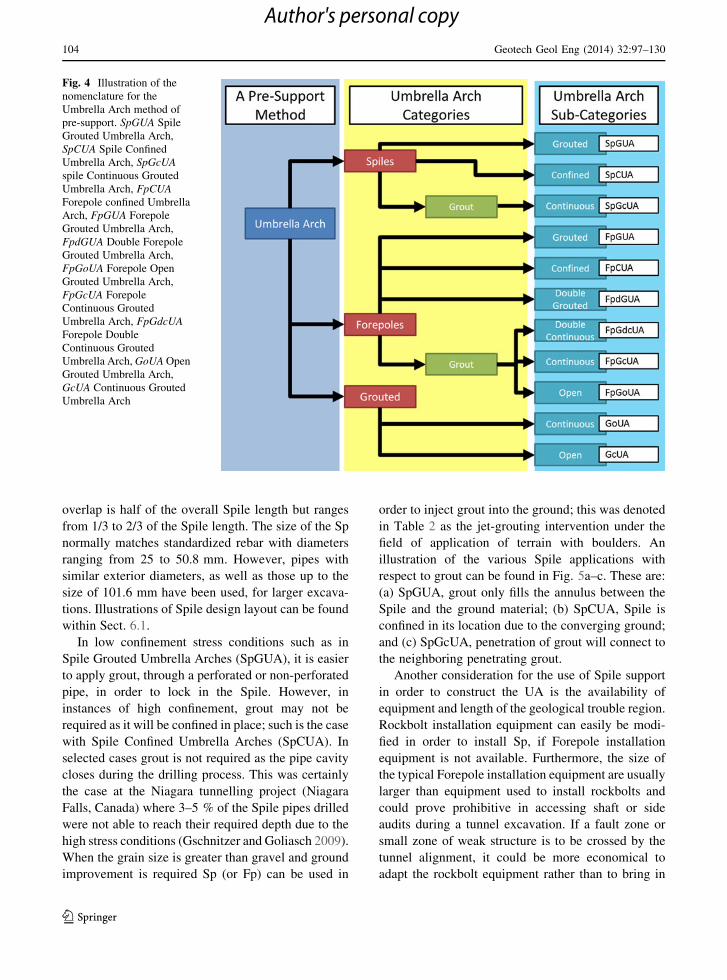
illustration of the various Spile applications with
respect to grout can be found in Fig. 5a–c. These are:
(a) SpGUA, grout only fills the annulus between the
Spile and the ground material; (b) SpCUA, Spile is
confined in its location due to the converging ground;
and (c) SpGcUA, penetration of grout will connect to
the neighboring penetrating grout.
Another consideration for the use of Spile support
in order to construct the UA is the availability of
equipment and length of the geological trouble region.
Rockbolt installation equipment can easily be modi-
fied in order to install Sp, if Forepole installation
equipment is not available. Furthermore, the size of
the typical Forepole installation equipment are usually
larger than equipment used to install rockbolts and
could prove prohibitive in accessing shaft or side
audits during a tunnel excavation. If a fault zone or
small zone of weak structure is to be crossed by the
tunnel alignment, it could be more economical to
adapt the rockbolt equipment rather than to bring in
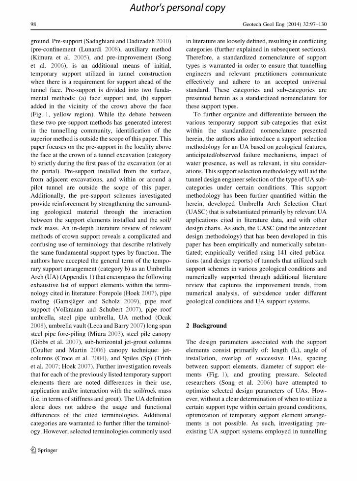
Fig. 4 Illustration of the
nomenclature for the
Umbrella Arch method of
pre-support. SpGUA Spile
Grouted Umbrella Arch,
SpCUA Spile Confined
Umbrella Arch, SpGcUA
spile Continuous Grouted
Umbrella Arch, FpCUA
Forepole confined Umbrella
Arch, FpGUA Forepole
Grouted Umbrella Arch,
FpdGUA Double Forepole
Grouted Umbrella Arch,
FpGoUA Forepole Open
Grouted Umbrella Arch,
FpGcUA Forepole
Continuous Grouted
Umbrella Arch, FpGdcUA
Forepole Double
Continuous Grouted
Umbrella Arch, GoUA Open
Grouted Umbrella Arch,
GcUA Continuous Grouted
Umbrella Arch
104 Geotech Geol Eng (2014) 32:97–130
123
Author's personal copy
Forepole equipment. It is important to note that is also
possible to install Forepole elements with equipment
used for Sp, if the Fp are installed in segments.
2.2.2 Forepoles
Forepoles are installed when a difficult and/or weak
material is consistent for a large portion of the tunnel
alignment and where there is a large potential for
multiple geological structures of unfavourable orien-
tation/structures to contribute to a possible failure. As
previously mentioned, Fp have a larger diameter than
Sp and their lengths are greater than the height of
excavation. The stability of the face of the tunnel is
derived by the fact that the Fp are long enough to
embed themselves past the empirically derived Ran-
kine active line, as shown in Fig. 6. This design length
is generally in agreement with Wang (2012), Fang
et al. (2012), and Wittke et al. (2006). Another
consideration for the length is that it exceeds the
ensuing plastic region around and ahead of the face
within these weak rock regions as illustrated in
Vlachopoulos and Diederichs (2009). In addition, the
angle of installation is shallow and typically between
3� and 8� from the horizontal in the longitudinal
direction of the tunnel alignment. The typical theo-
retical drilling accuracy is ±2 % relative to the pipe
length (Mager and Mocivnik 2000). The center to
center spacing of the Fp is within the range of
30–60 cm, however, the spacing is defined by the
requirement to create an individual arching effect in-
between two sets of Fp (overlapping influence of
support elements). The arching effect is also defined
by the size of the Fp, which have an outside diameter
Fig. 5 Divisions of Spiles and Forepoles. a–c divisions of
Spiles within the umbrella arch (cross-sectional view of support
element). a SpGUA, grout only fills the annulus between the
spile and the ground material; b SpCUA, spile is confined in its
location due to the converging ground; c SpGcUA, penetration
of grout will connect to the neighboring penetrating grout.
Illustration shows a solid bar acting as the spile, however, pipes
can also be used for this purpose. d–f divisions of Forepoles
within the umbrella arch (cross-sectional view of support
element). d FpGUA (FpdGUA), grout only fills the annulus
between the Forepole and the ground material, e FpCUA,
Forepole is confined in its location due to the converging
ground, f FpGoUA, penetration of grout will not connect to the
neighboring grout Forepole for open applications. FpGcUA,
(FpGdcUA) penetration of grout will connect to the neighboring
penetrating grout Forepole continuous application. Illustration
shows a pipe acting as the Forepole, however, sold bars can be
used
Geotech Geol Eng (2014) 32:97–130 105
123
Author's personal copy

of 60–168.3 mm and a wall thickness of 5–10 mm.
The overlap of the Fp range between 0 and 1/2 of the
Forepole’s length. The range usually depends on the
use of additional pre-support methods that aid in the
prevention of collapse of the face, such as face bolting.
If the overlap of the successive Forepole UA’s is
greater than � of the Forepole length, it is referred to a
double Forepole as there will always exist two layers
of support between the tunnel wall and surrounding
rock mass.
An illustration of the various Forepole applications
with respect to grout can be found in Fig. 5d–f. (d) Fp
can also be installed without grout, depending on the
confinement (FpCUA—Fig. 5d). (e) However, if con-
vergence must be controlled, the system can also be
stiffened with the inclusion of grout (FpGUA—
Fig. 5e). (f) If the system must be further stiffened or
the inflow of water is an issue, grout can be employed to
strengthen the material properties of the surrounding
material (FpGoUA—FpGcUA—Fig. 5f). Depending
on the risk, the stiffness or zone of permeability can be
strengthened by ensuring that the grout penetration is
being overlapped and/or employing the addition of a
second layer of reinforcement (overlap [L/2) (Fpd-
GUA—FpGcdUA).
2.2.3 Grouted
Grouting is commonly used in tunnelling projects as a
preventive measure to control water seepage. It is also
used to strengthen ground material, fill voids, secure
bolts, rods (Sp or Fp), and, in the case of drilled holes,
act as anchors (Warner 2004). This sub-category of
UA support is referred to only when grout is used
independently. Installation is similar to the installation
required for Fp and Sp in terms of angle of installation
and overlap. Spacing, however, is defined by the
allowable grouting pressure (which will ultimately
define the radius of grout) as well as the requirement
for the grouted zone to be connected (i.e. each grouted
support element is installed separately but attached to
each adjacent element, providing a continuous or
uninterrupted arch structure) or open (i.e. each grouted
support element is installed separately with spaces
between the elements that create the arch structure).
These types of grouted Umbrella Arches have been
sub-categorized as grouted continuous Umbrella
Arches (GcUA) and grouted open Umbrella Arches
(GoUA) respectively. The length of a grouted UA
depends on the availability of equipment but typically
it is more economical to grout within the range of
length of a Forepole (i.e. the length of the longitudinal
support element that comprises the UA is greater than
the height of excavation).
Since grout was first introduced in the 1800s as a
means for reducing water leakage (decreasing perme-
ability, j) in bedrock underlying dams (Warner 2004),
many types of grout have been developed for a variety
of conditions as shown in Fig. 7. Furthermore, an
understanding of the grout/material interaction has
advanced significantly. The strength and/or reduction
of a soil’s expansiveness and the resulting reduction of
swelling due to the mixture of calcium and clay soil, is
one such advancement (Warner 2004). Grouting
techniques can also increase the soil’s cohesion
strength and density (Warner 2004) minimizing sub-
sidence. If this process is not properly monitored, it
could lead to heave or breakthrough at the surface
(Groutjacking). Furthermore, Grouting does not
increase (in fact, in some cases it decreases) the
frictional angle of the material (Shin et al. 2006). The
selection of the grout method should be performed by
Fig. 6 Illustration of the
Rankine failure line of a
Double Forepole Confined
Umbrella Arch (FpdGUA)
(modified after Wang 2012)
106 Geotech Geol Eng (2014) 32:97–130
123
Author's personal copy

an experienced engineer because the selection grout-
ing application still cannot be reduced further than the
appropriate grain size type and stress conditions.
Table 4 outlines examples of the various methods with
respect to the jet-grouting (mixing) system only. Jet-
grouting can increase the compressive strength of silt,
sand, and gravel to a maximum of 5, 10, and 25 MPa
respectively (Keller 2013). The authors have included
herein examples of methods that have been published
in literature in subsequent sections.
Despite its importance as a parameter, pumping rate
information was not included within the summary of
the data that was collected for this investigation. The
pumping rate influences the compaction or consolida-
tion of the surrounding material. The higher the
pumping rate, the faster the project can achieve
completion. However, if compaction is to be used,
special care must be given to high pumping rate in
order to avoid soil fracturing.
3 Support Selection Methodology for an Umbrella
Arch
Due to the aforementioned inconsistency of terms and
their specific, relevant applications regarding UA
Fig. 7 Application limited for grouting techniques based on the work of (modified after Passlick and Doerendahi 2006)
Table 4 Typical injection parameters and respected column diameter for different jet-grouting systems (modified after Warner
2004)
Typical injection parameters Jet grouting system
1-Fluid 2-Fluid 3-Fluid
Standard Jumbo/super jet
Grout injection rate 38–113 L/min 68–132 L/min 567–660 L/min 68–132 L/min
Grout pressure 20–60 MPa 29–60 MPa 24.1–31 MPa 3.4–17 MPa
Air flow – 3,679–5,943 L/min 11,320–14,150 L/min 2,679–5,943 L/min
Air pressure – 0.6–1.2 MPa 0.8–1.4 MPa 0.6–1.2 MPa
Water flow – – – 68–151L/min
Water pressure – – – 20–50 MPa
Rotation rate (RPM) 10–25 5–10 3–4 2–10
Withdrawal rate 10–50 cm/min 7–30 cm/min 7.6–10 cm/min 5–30 cm/min
Material/typical column diameter
Cohesive soil 0.4–0.6 m 0.6–0.9 m 0.6–1.5 m 0.6–1.5 m
Granular soil Max 1.2 m Max 1.8 m Max 3.6 m Max 3.6 m
Geotech Geol Eng (2014) 32:97–130 107
123
Author's personal copy

methods, the authors propose an UA selection meth-
odology (Fig. 8). This UA selection methodology
separates the design discrepancies as well as outlines
the procedure for a specific UA technique based
primarily on increasing quantity of fracturing, and
confinement, control convergence, subsidence, and
water presence. Figure 8 acts as an illustrative design
aid for the UA (i.e. the decision to employ such a
support methodology has been taken) in response to
indications of difficult regions that require pre-
support. The support selection methodology for an
UA is present here in four distinct steps and is
explained further in the sub-sections which follow.
3.1 Step 1: Type
The first step in the design process consists of an
analysis and decision concerning whether pre-support
is required for the unexcavated tunnel profile at the
face. The selection of pre-support should depend on
the personal experiences of the tunnel designer and
contractor. For example, Lunardi (2008), the creator of
the analysis of controlled deformation in rocks and
soils (ADECO-RS) method prefers the pre-support of
core reinforcement with full face excavation over the
UA type methods. In addition, exceptionally difficult
terrain may call for the combination of multiple pre-
support methods (i.e. an arrangement of shoring of the
tunnel face, core reinforcement, and UA). It is outside
the scope of this paper to state which method is most
practical; however, if an UA is deemed appropriate,
the designer can proceed to the second step of the
selection chart.
3.2 Step 2: Mitigate Method
In the second step, the inclusion of a pre-support is
based on the mitigation measures required to counter
the expected behaviour of the ground due to tunnel
excavation. It is important to note, that the information
for this step should have been already been investi-
gated prior to the selection of the excavation method
Fig. 8 Methodology for selection process of umbrella arch
methods. Step 1 Requirement for pre-confinement. Step 2
Selection due to failure mode of ground material. Step 3 ground
conditions. Step 3.1 water presence. Step 4 selection process for
stiffness and water presence. The methods increase with
stiffness and protection from water as the selection process of
step 4 goes from the top left to the bottom right. SpGUA Spile
Grouted Umbrella Arch, SpCUA Spile Confined Umbrella Arch,
SpGcUA spile Continuous Grouted Umbrella Arch, FpCUA
Forepole confined umbrella arch, FpGUA Forepole Grouted
Umbrella Arch, FpdGUA Double Forepole Grouted Umbrella
Arch, FpGoUA Forepole Open Grouted Umbrella Arch,
FpGcUA Forepole Continuous Grouted Umbrella Arch,
FpGdcUA Forepole Double Continuous Grouted Umbrella
Arch, GoUA Open Grouted Umbrella Arch, GcUA Continuous
Grouted Umbrella Arch
108 Geotech Geol Eng (2014) 32:97–130
123
Author's personal copy
(conventional or mechanical). Thus, the designer has
to decide as to the pre-investigated ground behaviour
type (Appendix 2) with the required mitigation
method. The following four possible outcomes have
been proposed based on increasing fracturing (i.e.
ranging from wedge to raveling failure) and increas-
ing convergence/subsidence management require-
ment (i.e. ranging from subsidence having no
effect of an adjacent building to condemnation of
the building):
(a) Structural control: This response denotes a
structural problem within the tunnel that must
be controlled in order to achieve safe excavation.
In other words, discontinuities generally govern
the failure model of the tunnel (i.e. wedge to
chimney). The decision to include an UA within
the preliminary design would require some form
of geological modelling and/or discontinuous
analysis in order to aid in the definition of the
anticipated structural failure. Furthermore, the
support could also be installed solely as a safety
precaution.
(b) Convergence management: This mode is con-
sidered when undesirable convergence begins to
occur due to the increase in gravity driven
failures (i.e. chimney to ravelling failure) and/or
increase stress conditions (squeezing failure). If
discontinuity failures or other forms of failure
occur before the installation of the first support,
an UA needs to be employed. If squeezing failure
occurs (at depth), an UA needs to be employed to
control the initial deformation, and to redistrib-
ute the stress conditions across other temporary
supports.
(c) Convergence reduction based on ground
improvement: This outcome is similar to the
previous one, with the exception that an analysis
would find that the material parameters (perme-
ability and/or cohesion) require improvement to
make excavation possible. For example material
grain size is too small, and could cause ravelling
in-between individual support elements of an UA
(spile or Forepole). Another example is that the
water presence requires a reduction of infiltration
of water to prevent degradation of the tunnel
face; and
(d) Subsidence management: This outcome signifies
that subsidence is a design factor and that
convergence must be controlled through the
employment of a stiff UA.
3.3 Step 3: Geological Condition
The in situ stress confinement defines the geological
condition for mitigation 2a–c. The type of confinement
(high or low) will determine the temporary structural
support, the amount of grout (i.e. the stiffness of the
support) that will constitute the elements of the UA.
For the final mitigation method (2d) the impact of
tunnel subsidence will define the geological condition.
There are many different factors (i.e. infrastructure
in the vicinity of the tunnel) which contribute to the
limitations placed upon of tunnel subsidence. For
example, the Aeschertunnel in Canton Zurich, Swit-
zerland (Coulter and Martin 2006) had a subsidence
limitation imposed associated with a sewer line. It can,
however, be difficult to assign values of displacement
on such a linear structure that might cause damage or
failure of the sewer line; An analysis taking into
account the Serviceability Limit State and Ultimate
Limit State for tensile and compressive strain be
conducted. The tensile strain associated with cast iron
and lining concrete is 0.03 and 0.1 %, steel 0.5 and
0.1 %, ductile cast iron 0.1 and 0.2 %, and for plastic
materials 0.7 and 2.0 % (Leca and Barry 2007). With
regards to settlement of buildings due to tunnelling
works, Aksoy and Onargan (2010) have summarized
the work of other authors such as Attewell et al.
(1986), in order to generate a range of maximum
subsidence to an associated classification of possible
building damage. Generally, if surface settlement is
reduced to \10 mm there should be no structural
damage.
3.3.1 Step 3.1: Water Presence
This step takes into account the influence of water with
respect to subsidence caused by lowering the water
table or deterioration of the tunnel face and the
foundation zone of the UA. Leca and Barry (2007)
state that the impact of lowering the ground water
table varies in proportion to its magnitude and radius
of influence: when localized, induced deformations
are often prone to generating large differential settle-
ments; when widely spread, the consequences are
generally less severe. Therefore, the associated
Geotech Geol Eng (2014) 32:97–130 109
123
Author's personal copy
support methods are measures which minimize the
water inflow into the tunnel, if there is a high impact
caused by the hydrology.
Dewatering techniques can be employed when
water is present. In such cases, subsidence should not
be an issue due to a drop in the water table. Dewatering
techniques could be installed either from outside or
inside the tunnel. This dewatering may be required as
groundwater at the tunnel face may induce failures due
to the hydraulic gradient worsening the mechanical
conditions, the pre-existing mechanical instabilities,
and the material properties (Leca and Barry 2007).
3.4 Step 4: Options: Choice of Umbrella Arch
Sub-category
The fourth step is the selection of the appropriate UA
sub-category. The substantiated decisions of the
previous 3 steps leads the designer to the final choice
of the UA sub-category that could be utilized for those
predetermined conditions and relevant factors. As can
be seen, more than one option can meet the require-
ments within the design chart. Closer analysis, how-
ever, may determine that a specific UA that has been
initially selected might not provide adequate stiffness.
To aid in the selection of the stiffer support, the layout
of the UA options increase in stiffness from left to
right and from top to bottom. If the issue of subsidence
is a possibility, as previously stated, an analysis should
be conducted in order to observe the effect of the
supported tunnel at the ground level.
4 Cited Literature for Umbrella Arches
The determination of the standardized terminology as
well as the development of the UA support selection
methodology was predicated upon the findings of over
141 tunnel and cavern projects that have been
published around the world. A summary of the results
as determined through a rigorous Literature Review
are documented in Table 3. The complete database of
relevant information of all cited case studies can be
accessed on-line. The authors can be contacted in
order to provide interested parties with the salient
particulars.
Nearly 50 years of UA applications make up the
cited literature. Figure 9 illustrates the distribution of
the literature review in terms of the date of the first
known publication and the type of UA support that
was used. The various types of UA sub-category
employed within the last half-decade illustrate the
relevance and significance of this type of support
within the tunnelling field. In addition to the applica-
bility of such methods a significant trend that has been
observed is that there is an increase in the use of UA
references within the recent past. Such an increase
suggests an increased interest in this application
method, the suitability of such methods to be
employed and the importance of standardizing the
nomenclature and sub-categories of the UA. As an
addition attestation, the Literature Review exposes
numerous instances of published data which does not
provide adequate enough information in order to
classify the UA. The cases that do not provide
adequate information are listed as Fp, G, and Sp (in
which unsatisfactory or inconclusive information
exists on grout or overlap) and are also listed as ‘‘?’’,
in which an UA was described but no technical design
parameters were provided. The majority of the ‘‘?’’
cases are cited from publications which deal primarily
with the geological conditions of a tunnelling project,
as opposed to the tunnel construction and/or structure.
5 Umbrella Arch Selection Chart
The UASC was developed by the authors in an attempt
to simplify the choice of UA based primarily on the
use of relevant cited literature, previously mentioned.
The chart can be seen in Fig. 10. The chart also serves
to validate the methodology for the selection process
of UA sub-categories (as per Sect. 3 and depicted in
Fig. 8). The chart is firstly separated into the control
measures required to mitigate the anticipated behav-
iour in terms of structural control, convergence
management, convergence reduction and subsidence
management. The compilation and determination of
which UA type to use within each of these anticipated
ground responses and/or limitations is summarized in
each of the subsections below.
5.1 Structural Control
In an effort to aid in steps that are involved in the
support selection methodology for an UA (i.e. Steps 2
and 3 as defined in the previous section) the incorpo-
ration of the tunnel behaviour chart (TBC) by Marinos
110 Geotech Geol Eng (2014) 32:97–130
123
Author's personal copy

(2013) can be utilized for the structural control
(Appendix 2). The TBC allows the designer to predict
the failure case, which is also associated with over-
burden (confinement of the ground material). The
authors have practically paired up tunnel behaviour
cited in case studies cited in literature with the TBC
equivalents in order to validate the design chart for the
structural control section.
5.2 Convergence Management
Similarly, the TBC was also employed to quantify the
selection of an UA under the mitigation method of
convergence management. However, the TBC solely
would not able to differentiate the differences between
UA elements, Fp and Sp. That selection process would
still be up to the tunnel design engineers’ judgement.
5.3 Convergence Reduction Based on Ground
Improvement
The TBC could not completely simplify the conver-
gence reduction mitigation method as due to its
limitations. One limitation is that the TBC only takes
into consideration materials that are able to be
processed by GSI, as opposed to soil. A second
limitation is that the TBC does not further classify the
effect of ground water. The TBC does note that the
presence of water does not generally change the failure
mode, but does affect the factor of safety. The only
failure mode that water has a large effect on is
chimney, and ravelling (only from blocky-disturbed
and disintegrated) which would result in a flowing
ground failure mode.
The convergence reduction based on ground
improvement section could be simplified through the
Fig. 9 The distribution of the earliest referenced publication
date cited for umbrella arches. SpGUA Spile Grouted Umbrella
Arch, SpCUA Spile Confined Umbrella Arch, SpGcUA spile
Continuous Grouted Umbrella Arch, FpCUA forepole confined
umbrella arch, FpGUA Forepole Grouted Umbrella Arch,
FpdGUA Double Forepole Grouted Umbrella Arch, FpGoUA
Forepole Open Grouted Umbrella Arch, FpGcUA Forepole
Continuous Grouted Umbrella Arch, FpGdcUA Forepole
Double Continuous Grouted Umbrella Arch, GoUA Open
Grouted Umbrella Arch, GcUA Continuous Grouted Umbrella
Arch. Inconclusive information involving a spile element (Sp).
Inconclusive information involving a forepole element (Fp).
Inconclusive information involving a grout element (G).
Combination of forepole, Spiles, and grout, resulting in a
different classification (combination). Inconclusive information
involving an umbrella arch (?)
Geotech Geol Eng (2014) 32:97–130 111
123
Author's personal copy

addition of the grain sizes into the selection chart. For
example, it is suggested by John and Mattle (2002) if
sand or gravel lenses are to be expected, two rows of
tubes shall be provided. But if the excavation material
is completely cohesionless, then grouting is required.
With reference back to Fig. 7, most methods of
grouting materials/methods within the figure cannot
be installed within grain sizes larger than cobble. The
two grout materials listed that were successfully
installed within cobble are most commonly installed
through an injection method. Injection method can
easily be incorporated with Spile or Forepole supports
elements through the incorporation of injection ports.
Such division of grain size have been incorporated in
the UASC, and verified by selected published
literature. Further simplification of convergence
reduction based on ground improvement section was
not quantified in order to avoid standardization of
inexperienced engineers as the authors deem that
selection remains a case by case process.
5.4 Subsidence Management
The Subsidence Management section was based on the
literature review gathered (as previously mentioned)
of a variety of tunnelling projects and numerical
analysis results (Fig. 11; Table 5). The tunnelling
projects had either conducted numerical analysis or
observed the reduction of surface settlements due to
the employment of an UA (Table 5). Characteristic
Fig. 10 Umbrella Arch Selection Chart. SpGUA Spile Grouted
Umbrella Arch, SpCUA Spile Confined Umbrella Arch,
SpGcUA spile Continuous Grouted Umbrella Arch, FpCUA
forepole confined umbrella arch, FpGUA Forepole Grouted
Umbrella Arch, FpdGUA Double Forepole Grouted Umbrella
Arch, FpGoUA Forepole Open Grouted Umbrella Arch,
FpGcUA Forepole Continuous Grouted Umbrella Arch,
FpGdcUA Forepole Double Continuous Grouted Umbrella
Arch, GoUA Open Grouted Umbrella Arch, GcUA Continuous
Grouted Umbrella Arch
112 Geotech Geol Eng (2014) 32:97–130
123
Author's personal copy
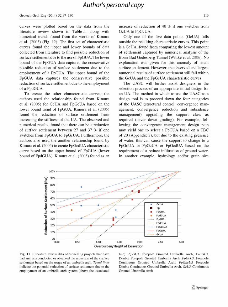
curves were plotted based on the data from the
literature review shown in Table 5, along with
numerical trends found from the works of Kimura
et al. (2005) (Fig. 12). The first set of characteristic
curves found the upper and lower bounds of data
collected from literature to find possible reduction of
surface settlement due to the use of FpGUA. The lower
bound of the FpGUA data captures the conservative
possible reduction of surface settlement due to the
employment of a FpGUA. The upper bound of the
FpGUA data captures the conservative possible
reduction of surface settlement due to the employment
of a FpdGUA.
To create the other characteristic curves, the
authors used the relationship found from Kimura
et al. (2005) for GcUA and FpGcUA based on the
lower bound trend of FpGUA. Kimura et al. (2005)
found the reduction of surface settlement from
increasing the stiffness of the UA. The observed and
numerical results, found that there can be a reduction
of surface settlement between 27 and 37 % if one
switches from FpGUA to FpGcUA. Furthermore, the
authors also used the another relationship found by
Kimura et al. (2005) to create FpGcdUA characteristic
curve based on the upper bound of FpGUA (lower
bound of FpdGUA). Kimura et al. (2005) found as an
increase of reduction of 40 % if one switches from
GcUA to FpGcUA.
Only one of the five data points (GcUA) falls
outside the resulting characteristic curves. This point
is a GcUA, found from comparing the lowest amount
of settlement captured by numerical analysis of the
Bonn-Bad Godesberg Tunnel (Wittke et al. 2006). No
explanation was given for this anomaly of small
surface settlement. However, the observed and largest
numerical results of surface settlement still fall within
the GcUA and the FpGcUA characteristic curves.
The UASC will further assist designers in the
selection process of an appropriate initial design for
an UA. The method in which to use the UASC as a
design tool is to proceed down the four categories
of the UASC (structural control, convergence man-
agement, convergence reduction and subsidence
management) upgrading the support class as
required (never down grading). For example, fol-
lowing the convergence management design path
may yield one to select a FpCUA based on a TBC
of 20 (Appendix 2), but due to the existing presence
of water, this can cause the support to change to a
FpGoUA or FpGcUA or FpGcdUA based on the
requirement of a reduce infiltration of ground water.
In another example, hydrology and/or grain size
Fig. 11 Literature review data of tunnelling projects that have
had analysis conducted or observed the reduction of the surface
settlement based on the usage of an umbrella arch. Trend lines
indicate the potential reduction of surface settlement due to the
employment of an umbrella arch system (above the associated
line). FpGUA Forepole Grouted Umbrella Arch, FpdGUA
Double Forepole Grouted Umbrella Arch, FpGcUA Forepole
Continuous Grouted Umbrella Arch, FpGdcUA Forepole
Double Continuous Grouted Umbrella Arch, GcUA Continuous
Grouted Umbrella Arch
Geotech Geol Eng (2014) 32:97–130 113
123
Author's personal copy

conditions could result in determining that a GcUA
be employed based on convergence reduction mit-
igation method. However, an additional design
requirement of controlling subsidence (i.e. subsi-
dence management) could result in the employment
of an FpdGUA in order to ensure the reduction of
surface settlement of 30 %, if overburden to height
of excavation ratio of 1. GcUA would govern the
design as it will meet both requirements: ground
improvement; and surface settlement reduction of
great than 30 % (44 %).
6 Employment of Umbrella Arch Methods
The following subsections define each of the individ-
ual sub-categories of the UA. For the majority of the
individual sub-categories, a tunnel example is refer-
enced in order to illustrate the practicality and
employability of the proposed support selection pro-
cess. The Case Studies that have been cited and that
are used for illustration purposes are summarized in
Table 6. Furthermore, in order to illustrate (and
validate) the UA support selection process, each case
Table 5 Literature review of tunnelling projects that have had analysis conducted or observed the reduction of the surface settlement
based on the usage of an Umbrella Arch
Tunnel Reference UA
method
used
Overburden/
height of
excavation
Settlement
without UA
(mm)
Settlement
with UA
(mm)
Reduction of
surface
settlement (%)
Aeschertunnel Coulter and Martin
(2006)
GcUA 2.58 350a 25a 93
Underground station
‘‘Taborstrabe’’
Pichler et al. (2003) GcUA 1.00 90b 45b 50
Bonn-Bad Godesberg Tunnel Wittke et al. (2006) GcUA 0.59 65a 15a 77
Bonn-Bad Godesberg Tunnel Wittke et al. (2006) GcUA 0.59 65a 45a 31
Bonn-Bad Godesberg Tunnel Wittke et al. (2006) GcUA 0.59 65a 33b 49
Taksim to Yenikapi (Istanbul
metro line)
Yasitli (2012) FpGUA 1.82 109.7a 45.6a 58
Taksim to Yenikapi (Istanbul
metro line)
Yasitli (2012) FpGUA 1.82 138b 40b 71
Fort Canning tunnel Yeo et al. (2009) FpGUA 0.82 100a 80a 20
Istanbul Metro (Zone F to Zone
C) between Unkapani and
Yenikapi
Ocak (2008) FpGUA 1.98 140a 40a 71
Istanbul Metro (Zone G to
Zone A) between Unkapani
and Yenikapi
Ocak (2008) FpGUA 2.45 370a 90a 76
Based on Trojane Tunnel (30
pieces)
Volkmann and
Schubert (2006)
FpGUA 1.36 250a 175a 30
Based on Trojane Tunnel (20
pieces)
Volkmann and
Schubert (2006)
FpGUA 1.36 250a 181a 28
Based on Trojane Tunnel (10
pieces)
Volkmann and
Schubert (2006)
FpGUA 1.36 250a 197a 21
Based on Trojane Tunnel (20
pieces ?)
Volkmann and
Schubert (2006)
FpGUA 1.36 250a 173a 31
Dulles Corridor Metrorail
Project
Gall et al. (2011) FpdGUA 0.36 35b 20b 43
Izmir Metro Aksoy and Onargan
(2010)
Fp 1.97 23a 7b 70
a Numerical datab Observed data
114 Geotech Geol Eng (2014) 32:97–130
123
Author's personal copy

study presented also includes the process and assess-
ment (through the use of the UASC).
6.1 Employment of Spiles
6.1.1 Buon Kuop Hydropower Project
According to Trinh et al. (2007), one of the tunnels of
the Buon Kuop hydropower project, in Vietnam, hit a
zone of weakness that was 15–20 m long during a twin
tunnel drill and blast excavation. The result of
excavating in this weakness zone was a cave-into the
surface (60 m above the excavation), which, in turn,
created a sink hole. Utilizing the information provided
by Trinh et al. (2007) and applying it to the UASC, this
would result in a preliminary design selection of a
SpGUA. The selection of the SpGUA would be based
on a requirement for convergence management as the
weakness zone encountered (15–20 m long) prevented
further excavation with some sort of pre-support. The
available equipment only allowed for the installation
of rods that measured 6 m in length, therefore it was
not economical to use other methods associated with
support elements of a longer length (i.e. Fp) for such a
short section of the overall tunnel alignment. SpGUA
would have been selected based on the TBC #13 due to
the block structure (GSI value range of 20–30 with
Fig. 12 Left observed longitudinal surface settlement for the
Baikoh tunnel excavation (modified after Kimura et al. 2005).
Right new urban tunnelling method (NUTM) (modified after
Kimura et al. 2005). The difference between the NUTM design
and piperoof is the addition of the horizontal jet grouting
underneath the long steel pipe forepiling and the jet-grouting
side foundations. Piperoof would be classified as a FpGUA, and
the NUTM would classify as a FpGcUA, due to the possible
interaction of the jet-grouting installed just below the crown
Table 6 Summary of published employment of Umbrella
Arch methods
Tunnel Publication UASC
selection
Buon Kuop
Hydropower Project
Trinh et al. (2007) SpCUA
Platanos Tunnel Marinos and
Tsiambaos (2010)
SpGUA
Kukuan Tailrace
Hydropower Plant
Tunnel
Liu et al. (2010) SpGcUA
Platamon(as) Pilot
Tunnel
Marinos and
Tsiambaos (2010)
FpGUA
Tunnel San Fedele
(Roveredo bypass
project)
Fasani et al. (2012) FpGoUA
Maiko Tunnel Harazaki et al. (1998) FpGcUA
Driskos Tunnel (Egnatia
Odos)
Vlachopoulos et al.
(2013)
FpCUA
Golovec Tunnel Bizjak and Petkovsek
(2004)
FpdGUA
&
SpGUA
Seoul Subway Line 9
(construction site 912)
Kim (2008) FpGdcUA
Malakasi C Twin
Tunnel
No published data,
authors personal
notes
GoUA
Aeschertunnel Coulter and Martin
(2006)
GcUA
Geotech Geol Eng (2014) 32:97–130 115
123
Author's personal copy

Fair to Poor joint conditions), overburden \70 m
(60 m), and with a rci value of \15 MPa
(10.84 MPa).
However, further investigation would show that
this zone of weakness occurred in a valley of two
mountain ranges (Fig. 13a), resulting in higher stress
conditions than were indicated by the pure overbur-
den. The higher stress conditions would eliminate the
grout requirement, which would result in SpCUA as
the final selection of the UA to traverse the weakness
zone.
The SpCUA used at the Buon Kuop hydropower
project consisted of the following: 6 m long Sp which
were installed around the crown of the 9 m high
excavation; 50 mm in diameter support which were
spaced at 35 cm and installed at an angle 16� from the
tunnel axis, and, as previously mentioned, confined in
their location. An illustration of the design for the
cave-in tunnel and the second tunnel design as it
encountered the weakness zone are presented in
Fig. 13b, c, respectively. More information on the
Buon Kuop hydropower project in Vietnam is
described in Trinh et al. (2007).
6.1.2 Platanos Tunnel
The Platanos tunnel project, in Greece, is consisted of
15 different combinations of support classes within
varying geological conditions. All 15 designs incor-
porate UA type supports, with nine of the 15
combinations using Sp. Six (6) of the nine Spile
designs were based on structural type failure (at low
overburden) where the ground conditions contain few
indications of loose to slightly cemented coarse grain
material (conglomerate). This local failure could,
potentially cause failures similar to TBC #9, 10, 13,
and 14; these results in a SpGUA installed locally in
regions with such conditions. A layout of the general
support with Forepole of the Platanos Tunnel can be
found within Figs. 14 and 15.
There were three different types of SpGUA used at
the Platanos 11 m high excavation. The three different
SpGUA varied by different stiffness’s associated with
the tunnel overburden and/or weaker materials
encountered. The different Sp had diameters ranging
from 28 to 32 mm rods (with a maximum overburden
of 50 m), and 51 mm (5 mm thickness) pipes (with a
maximum overburden of 100 m). All Sp had a length
of 6 m with a center to center spacing ranging from 25
to 35 cm. For further information about this Platanos
tunnel and the other structural supports used during
construction please refer to the following design
documents (as summarized in Marinos and Tsiambaos
(2010)).
6.1.3 Kukuan Tailrace Hydropower Plant Tunnel
The UA that was selected for the preliminary design of
the Kukuan tailrace hydropower plant tunnel, in
Taiwan, was based on the information provided within
Liu et al. (2010). The ground material was described as
highly fractured sandstone and slate that was satu-
rated. As such, it was necessary to create a grout
sealing around the 7.6 m high tunnel excavation as the
tunnel was being constructed underneath a river in
material with permeability of 13–17 9 10-5 cm/s.
Fig. 13 a Cave-in at the first headrace tunnel (modified from PMU5, 2005), b Excavation in the first tunnel of Buon Kuop hydropower
project. c Excavation in the second tunnel—longitudinal sections of Buon Kuop hydropower (Trinh 2006)
116 Geotech Geol Eng (2014) 32:97–130
123
Author's personal copy
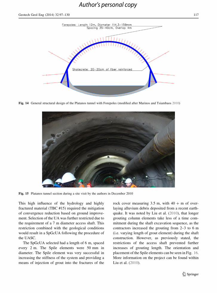
This high influence of the hydrology and highly
fractured material (TBC #15) required the mitigation
of convergence reduction based on ground improve-
ment. Selection of the UA was further restricted due to
the requirement of a 7 m diameter access shaft. This
restriction combined with the geological conditions
would result in a SpGcUA following the procedure of
the UASC.
The SpGcUA selected had a length of 6 m, spaced
every 2 m. The Spile elements were 50 mm in
diameter. The Spile element was very successful in
increasing the stiffness of the system and providing a
means of injection of grout into the fractures of the
rock cover measuring 3.5 m, with 40 ? m of over-
laying alluvium debris deposited from a recent earth-
quake. It was noted by Liu et al. (2010), that longer
grouting column elements take less of a time com-
mitment during the shaft excavation sequence, as the
contractors increased the grouting from 2–3 to 6 m
(i.e. varying length of grout element) during the shaft
construction. However, as previously stated, the
restrictions of the access shaft prevented further
increases of grouting length. The orientation and
placement of the Spile elements can be seen in Fig. 16.
More information on the project can be found within
Liu et al. (2010).
Fig. 14 General structural design of the Platanos tunnel with Forepoles (modified after Marinos and Tsiambaos 2010)
Fig. 15 Platanos tunnel section during a site visit by the authors in December 2010
Geotech Geol Eng (2014) 32:97–130 117
123
Author's personal copy

6.2 Employment of Forepoles
6.2.1 Platamon(as) Pilot Tunnel
The Platamon(as) tunnel is a twin highway tunnel
connecting Athens with Thessaloniki, Greece. During
excavation the north bound traffic tube had a 40 m
long collapse at the tunnel face, this propagated to the
south bound tunnel causing a 20 m long collapse at its
face. To proceed through the failed region, a pilot
tunnel was required. During a site visit, in December
2012, the authors were able to inspect the geological
conditions and found that a FpGUA would have been
selected as a preliminary design based off of the
UASC. The preliminary report for the project indi-
cated that the material at the problematic section
would be a disintegrated serpentinized peridotite/scree
material with a GSI of 5–15 with 10 m of overburden
(TBC #17). The north bound tunnel was being over
excavated during a site investigation conducted by the
authors. This opportunity allowed for an assessment of
the material. The material was classified as a highly
serpentinized preidotites, tectonically sheared to clay-
like material with hard clasts up to 3 cm diameter
(Fig. 17). The overburden of the tunnel was approx-
imately 17 m (TBC #21). Furthermore, Fp were easily
employed as the machinery used to install them was
already on site.
The support class employed at the failed sections
was support 7A, using a FpCUA. The FpCUA
employed was 12 m long, 114 mm in diameter, with
4 m of overlap. The support was installed covering
100� of the crown, of the almost 12 m high excavation.
For further information on the support classes and
other design parameters can be found in Marinos and
Tsiambaos (2010).
It is important to note that the over excavation
employed an UA type technique as shown in Fig. 17.
However, these supports were not installed during the
first past, which falls outside the authors’ description
and the UA.
6.2.2 Tunnel San Fedele (Roveredo Bypass Project)
The material encountered at the southern section of
the Roveredo bypass project, in Switzerland, con-
sisted of slightly silty gravels with abundant to
predominant sand, stones, and blocks with a max-
imum of 25 m of overburden. (Fasani et al. 2012).
The material has no genuine cohesion and is only
slightly interlocked. The UASC would place the
requirement for pre-support as a convergence reduc-
tion based on ground improvement. The impact of
water low, as the water table was below the
excavation and the impact at surface can be omitted
based on the land is primarily farmland. The
presence of stones and blocks would push the
selection to a FpGoUA support type (with drainage)
as grouting techniques such as jet-grouting are not
ideal in materials with such large grain sizes.
The actual selection of the temporary tunnel
support was a FpCUA (no reference to grout used
within support description) that was 15 m long, on the
*6 m high top heading excavation, with 5 m of
Fig. 16 Cross sections of the SpGcUA Kukuan Tailrace hydropower plants tunnel (modified after Liu et al. 2010)
118 Geotech Geol Eng (2014) 32:97–130
123
Author's personal copy

overlap (Fig. 18). The Fp were spaced at 50 cm (20
pipes on during excavation of the top heading) in
combination with 12 m long face anchors to ensure
stability of the face. A loose section was encountered
at the south portal and was persistent for approxi-
mately 150 m. However, the spacing allowed for grain
sizes smaller then 40 cm to pass through the Fp. The
material lost was backfilled with concrete, however, at
a selected location there was a propagation of a
chimney type failure to the surface (Fig. 19). This
failure lead to reduction of the Forepole element
spacing from 50 to 40 cm, and the application of
grouting in the loose ground sections. Further details
associated with the San Fedele Tunnel can be found in
Fasani et al. (2012).
6.2.3 Maiko Tunnel
According to Harazaki et al. (1998), the Maiko
Tunnel in Kobe, Japan, is a 3.3 km twin highway
that has an excavation width of 16 m and height of
11–12 m. Two geological conditions were encoun-
tered: (1) Alluvial zone (uncemented sand and
gravel in alluvium and embankments); and (2)
diluvial zone (uncemented gravel and clay). The
ground water was found to be near ground surface
Fig. 17 Over excavation of the pilot tunnel in the south bound tunnel, December 2012
Fig. 18 Tunnel San Fedele (Roveredo bypass project) south portal during a site visit by the authors in 2011
Geotech Geol Eng (2014) 32:97–130 119
123
Author's personal copy

for both zones. The tunnel passes 4–7 m under an
athletic ground of a school and close to existing
school buildings (closest building is 10 m from the
excavation). Pre-support was required, as construc-
tion from surface was not possible and given the
instability of the uncemented material (gravel and
sand). According to the UASC, a FpGcUA would
have been selected for both sections as convergence
reduction based on ground improvement because of
the presence of gravel/sand, low overburden, and
high presence of water. Surface subsidence was a
consideration due to the close proximity of the
school buildings. Due to the fact that the existing
surface infrastructure is approximately an excava-
tion height distance away from the centreline of the
tunnel, combined by the fact that the UA support
selected is the second stiffest type of UA, the effect
on the surface settlement at the surface will be
minimal to insignificant if design correctly. No
damage to the school building infrastructure was
recorded in the publication of Harazaki et al.
(1998).
Harazaki et al. (1998) describes the pre-support
system used as an umbrella method (umbrella fore-
pile) which consisted of long steel pipes and consol-
idation grouting (FpGcUA). The pipes had a length of
12 m, diameter of 114.3 mm and a thickness of 6 mm.
The maximum surface settlement was found to be
100–120 and 20 mm for the alluvial and diluvial zone
respectively. Due to the large surface settlement in the
alluvial zone, the standard cement mortar was
replaced with ultrafine cement mortar; improved
support performance metrics were not provided based
on this change. More information can be found within
Harazaki et al. (1998).
6.2.4 Driskos Tunnel (Egnatia Odos)
The design of weakest section (very thin bedded
sandstones and thin bedded siltstones, Sect. 4 of cited
reference) of the Driskos Tunnel, in Greece, required
an UA (Fig. 20) to be able to excavate through the
fractured flysch material (Vlachopoulos et al. 2013).
The Umbrella Selection Chart would have selected a
FpCUA (over 650 m length of the overall tunnel
length) to provide convergence management. The
blocky to disintegrated material, with a rci of
26–75 MPa, with overburden range of 100–220 m
would yield a TBC #16 or 20.
However, FpGUA was selected by the designer
with the following specifications as shown in Fig. 21
for the 9.47 m high, horse-shoe tunnel excavation. The
Fp were 12 m long, 101 mm in diameter with 4 m of
overlap, and installed at an angle of 5.78� off of the
tunnel axis. For further information on the Driskos
tunnel, please refer to Vlachopoulos et al. (2013) and
Vlachopoulos (2009).
6.2.5 Golovec Tunnel
The Golovec Tunnel was constructed as part of the city
of Ljubljana’s ring road in Slovenia. The 10.5 m high
tunnel excavation was constructed with a low over-
burden (\80 m) with the added constraint of crossing
Fig. 19 Earth fall on 4 June
2010, cross-section at about
Tm 48 of Tunnel San
Fedele, (modified after
Fasani et al. 2012)
120 Geotech Geol Eng (2014) 32:97–130
123
Author's personal copy

under two roads. An UA was employed in order to
allow for excavation and also to reduce subsidence
that could potentially disrupt traffic flow on the road
above and minimize the risk of landslide. According to
Bizjak and Petkovsek (2004), a landslide occurred
during the first excavation of the tunnel portals. Once
the tunnel was excavated past the portal, landslide
region it encountered a zone of highly weathered
quartz sandstone, with a GSI range of 10–15. The
geological conditions would indicate a TBC #18.
Based on the requirement for convergence manage-
ment, a FpGUA would be selected using the UASC.
However, due to the presence of roads above the
tunnel excavation and the landslide potential, the
selection would fall into the Subsidence Management
section (resulting in the requirement of a numerical
analysis). A FpdGUA was found to control the
subsidence of the 10.5 m high tunnel excavation
during the worst of the geological conditions, how-
ever, the SpGUA was able to provide enough
Fig. 20 ‘‘Saw-tooth’’ profile of the umbrella arch installed in the Driskos tunnel
Fig. 21 Longitudinal
cross-section of Driskos
showing tunnel support
(class V) detail (modified
after Vlachopoulos et al.
2013)
Geotech Geol Eng (2014) 32:97–130 121
123
Author's personal copy

protection in more stable conditions (Bizjak and
Petkovsek 2004). The general layout of the tunnel
support case can be seen in Fig. 22.
The FpdGUA had an overlap of 6–9 m of the
12–15 m long Fp. The SpGUA had overlap of 3 m of
the 9 m long Sp. The Forepole/Sp used was a 4
(101.6 mm) iron pipes filled with mortar that were
spaced 30 cm apart (center to center). For more
information of the supports used on the project please
refer to Bizjak and Petkovsek (2004).
6.2.6 Seoul Subway Line 9 (Construction Site 912)
According to Kim (2008), the Seoul subway line 9 at
construction site 912 was constructed in an alluvial
deposit near the Han River. The 8.5 m high tunnel
section was constructed with only 18 m of overburden
and with the water Table 1. 5 m below surface. The
14-storey apartment buildings and five-story shopping
centers were also in close proximity to the construc-
tion site. Should the information provided by Kim
(2008), be applied to the UASC, it would result in a
preliminary design for a pre-support of minimum
stiffness of GcUA. The GcUA is the minimum support
that will meet the requirement for both mitigation
methods of ground improvement based on ground
improvement (due to the water present) and subsi-
dence management (impact of the infrastructure above
the tunnel). A FpGdcUA was successfully employed
with further dewatering techniques (Fig. 23) (Kim
2008).
The Forepole elements used as part of the
FpGdcUA were 114 mm diameter pipes, 13.5 m long,
with a center to center spacing of 60 cm. The grouting
process was classified as jet-grouting, with the whole
system overlapping 7.1 m with the grouting length
13.4 m. This resulted in a minimum of 2 layers of
reinforcement through the region underneath the
apartment buildings. For more information regarding
the Seoul Subway Line 9 at construction site 912
please refer to Kim (2008).
6.3 Employment of Grout
6.3.1 Aeschertunnel
The Aeschertunnel, in Switzerland, was constructed in
a glacial moraine which consisted of a brown clayey
sand and silt, with gravel and isolated boulders
(cohesion strength was 5–20 kPa). During excavation,
the unsupported vertical face showed no signs of
instability. A critical section of the tunnel alignment
was defined that consisted of overhead roadways, a
sewer line, a concrete stream diversion channel, and a
nearby house. These infrastructures could potentially
be affected by the subsidence of the tunnel with only
Fig. 22 Details of cross section of the Golovec tunnel (modified after Bizjak and Petkovsek 2004)
122 Geotech Geol Eng (2014) 32:97–130
123
Author's personal copy

13–15.5 m over overburden on the approximately 6 m
high heading excavation. If the Aeschertunnel condi-
tions were to be applied to the UASC, it would first
require a FpGcUA as there is reference to boulders.
Prior to the critical section, subsidence was recorded
to be of maximum magnitude of 350 mm. According
to the UASC, FpGcUA would yield a reduction of
surface settlement of about 93 % (25 mm). A subsi-
dence 25 mm is reasonable as it will only produce low
amount of damage to infrastructure according to
Attewell et al. (1986).
Nonetheless, the isolated boulders seemed not to be
an issue as GcUA was selected for the support. This
support was successful in controlling the subsidence
by creating a very narrow settlement trough, as well as,
a very low volumetric loss of 0.35 %. The GcUA
employed was 13 m long with 2 m of overlap
(Fig. 24). The grout columns were 600 mm in diam-
eter, spaced at 450 mm (center to center), and installed
at an angle of 11�. The Jet-grouting process utilized
had the following installation parameters: 40 MPa
pump pressure, a 1:1 grout to water ratio, a 15 rpm
drilling rod rotation ratio, a 0.5 m/min withdrawal
rate, and a 12 m3/h grout injection rate. For further
information on the Aeschertunnel please refer to
Coulter and Martin (2006).
7 Discussion/Summary of Findings
Based on Table 3 (generated from the cited literature
review) the authors were able to create a generalized
Fig. 23 Ground strengthening techniques and dewatering schema of the Seoul Subway Line 9 at construction site 912 (Left) excavation
method with jet grouting piles (right) dewatering scheme (modified after Kim 2008)
Fig. 24 Top-heading excavation showing jet-grout column numbering at the Aeschertunnel (modified after Coulter and Martin 2006)
Geotech Geol Eng (2014) 32:97–130 123
123
Author's personal copy

Ta
ble
7G
ener
aliz
edd
esig
np
aram
eter
so
fth
esu
bca
teg
ori
eso
fth
eU
mb
rell
aA
rch
Um
bre
lla
Arc
h(1
41
)
Sp
ile
(31
)F
ore
po
le(5
6)
Gro
ut
(15
)
Gro
ut(
1)
Gro
ut(
9)
Sp
CU
A
(4)
Sp
GU
A
(14
)
Sp
GcU
A(1
)F
pC
UA
(1)
Fp
GU
A
(23
)
Fp
dG
UA
(2)
Fp
Go
UA
(1)
Fp
GcU
A(1
)F
pG
dcU
A(6
)G
oU
A(0
)G
cUA
(6)
Ra
ng
eo
fU
mb
rell
aA
rch
des
ign
crit
eria
Len
gth
\H
e\
He
\H
e[
He
(\3
He)
[H
e
(\3
He)
[H
e
(\3
He)
[H
e(\
3H
e)
[H
e(\
3H
e)
[H
e(\
3H
e)
[H
e(\
6H
e)
[H
e(\
6H
e)
An
gle
(�)
5–
20
5–
20
5–
20
3–
83
–8
3–
86
–1
16
–1
16
–1
16
–1
16
–1
1
Ov
erla
p(m
)L
/3–
2L
/3L
/3–
2L
/3L
/3–
2L
/3\
L/2
\L
/2[
L/2
\L
/2\
L/2
[L
/21
–L
/21
–L
/2
Sp
acin
gce
nte
r-
to-c
ente
r(c
m)
\5
0\
30
\G
rou
t
dia
met
er
\6
03
0–
60
30
Gro
ut
dia
met
er
\G
rou
t
dia
met
er
\G
rou
t
dia
met
er
Gro
ut
dia
met
er
\G
rou
t
dia
met
er
Dia
met
er(m
m)
*g
rou
t
pen
etra
tio
n
25
–1
01
.62
5–
10
1.6
25
–1
01
.6
*m
ater
ial
dep
end
ant
89
–1
68
.38
9–
16
8.3
89
–1
68
.38
9–
16
8.3
*m
ater
ial
dep
end
ant
89
–1
68
3*
mat
eria
l
dep
end
ant
89
–1
68
.3
*m
ater
ial
dep
end
ant
*m
ater
ial
dep
end
ent
*m
ater
ial
dep
end
ent
Gro
ut
pre
ssu
re
(MP
a)
NA
0.2
0–
13
5–
80
NA
0.2
0–
10
.20
–1
35
–8
03
5–
80
35
–8
03
5–
80
35
–8
0
XX
–X
Xra
ng
eo
fd
ata,
XX
pu
bli
shed
case
s,H
eh
eig
ht
of
exca
vat
ion
,N
An
ot
app
lica
ble
,L
len
gth
of
sup
po
rt
124 Geotech Geol Eng (2014) 32:97–130
123
Author's personal copy

design table for each of the individual sub-categories
of the UA (Table 7). The generalized design proper-
ties included in this table will further aid the tunnel
designer in their process of choosing and creating the
numerical analysis to verify the chosen preliminary
design of the UA, selected from the support selection
methodology (or UASC). The support selection
methodology (Fig. 8) is intended as an illustrative
tool which provides an element of rationalization to
the selection of the appropriate UA. The UASC is a
quantitative approach of the support selection meth-
odology. As previously stated, however, the UASC is
currently based primarily on the TBC (Marinos 2013),
which was created from the analysis of 62 tunnels of
the Egnatia Odos highway project. Thus, should a
tunnelling project fall outside the applicability region
of the TBC, so too would the current version of the
UASC. Nonetheless, portions of the UASC process
have been empirically verified by case studies across
the globe and extrapolated in-between verifications.
Based on the current progress, it can be established
that as the TBC and UASC are further verified around
the world, and as the data base for the UA continues to
grow, the UASC will increase in applicability.
Another important factor involves surface settle-
ment. Within a numerical analysis, the surface
settlement (subsidence management section of the
UASC) can be reduced by a factor of 2–2.5, with
the addition of bearing capacity of the foundation of
the UA (Gioda and Locatelli 1999). Therefore, it
can be determined that the selection of the proper
UA is not the only critical factor when attempting
the reduction of surface settlement. This additional
foundational requirement explains why the research
of Pichler et al. (2003) found that the employment
of a stiffer material below the UA resulted in the
reduction of surface settlement by 32 % (compared
to no GcUA used), with a difference of 16 % more
than their homogenous model (48 % of surface
settlement). Therefore, when taking into consider-
ation design parameters, the tunnel designer must
also ensure the adequacy of the remainder of the
support system, in order to handle the transfer of
stress from the UA as well the complex geological
conditions.
The authors recommend for numerical analysis that
when grout is used solely in a continuous manor in an
UA, it can be simplified as homogenous region. This
homogenous region is improvement material zone to
simulate the GcUA. This is the only application of the
UA that can be modelled in 2D. The process of
modelling all other methods as homogenous regions
may provide an accurate solution empirically, but not
mechanistically (Oke et al. 2012). In these aforemen-
tioned cases, the homogenous regions would not
capture either the individual arching effect between
grout columns (GoUA) or structural steel (spile or Fp),
and the longitudinal support interaction.
8 Conclusions
In conclusion, this paper proposes a standardization of
nomenclature, a selection methodology for the UA
support, as well as, an UASC design tool; one that can
be accepted and utilized as a universally applied
standard. An extensive collection of literature of
support employed at actual tunnel construction sites
provided the empirical foundation and substantiation
for the proposed nomenclature and the detailed
description of each of the sub-categories of the UA.
Furthermore, the collection of cited literature provided
insight into the development of the selection method-
ology of an UA, based on the collected geological
conditions and stiffness of the support with respect to
the impact at the surface as well as stress conditions,
water presence and tunnel convergence/behaviour.
Overall, this proposed standard addresses the two
distinct and often overlooked voids within the field of
tunnel engineering within weak rock masses, stan-
dardization and methodology of the support utilized as
part of the UA support.
Acknowledgments This work has been funded by Natural
Sciences and Engineering Research Council of Canada, the
Department of National Defence (Canada) as well as graduate
funding obtained at Queen’s University and the Royal Military
College of Canada. The authors would also like to thank Dr. Paul
Marinos from the National Technical University of Athens,
Greece, for providing the opportunity to visit numerous tunnels
under construction in Greece, as well as, Dr. Jean Hutchinson
and Dr. Mark Diederichs from Queen’s University, Canada for
their input and advice as well as providing selected authors the
opportunity to visit numerous tunnel projects in Switzerland,
France, Italy, and Austria.
Appendix 1
See Table 8.
Geotech Geol Eng (2014) 32:97–130 125
123
Author's personal copy

Appendix 2
See Figs. 25 and 26.
Table 8 Summary of the terminology of the Umbrella Arch method, elements (3), and sub-categories (11)
Terminology Definition
Umbrella Arch A pre-support method that is installed during the first pass of excavation from
within the tunnel, above and around the crown of the tunnel face, that
reinforces through the interaction of support and the rock mass
Elements
Spile A support element of an Umbrella Arch that is metallic longitudinal members
that are shorter than the height of the tunnel
Forepole A support element of an Umbrella Arch that is metallic longitudinal members
that are greater than the height of the tunnel
Grouted A support element of an Umbrella Arch that simply consists of grout
Sub-categories
SpCUA A sub-category of an Umbrella Arch, that uses the spile element, which is held in
its position through the confinement of the converging rock mass
SpGUA A sub-category of an Umbrella Arch that uses the spile element, which is held in
its position through the employment of grout within the annulus of the element
and the overbored rock mass
SpGcUA A sub-category of an Umbrella Arch that uses a spile element to stiffen the
support and to act as a means of access of injection grout to create a continuous
layer of grouted rock mass
FpCUA A sub-category of an Umbrella Arch that uses the Forepole element, which is
held in its position through the confinement of the converging rock mass
FpGUA A sub-category of an Umbrella Arch that uses the Forepole element, which is
held in its position through the employment of grout within the annulus of the
element and the overbored rock mass
FpdGUA A sub-category of an Umbrella Arch that uses the a double layer of Forepole
elements, which is held in its position through the employment of grout within
the annulus of the element and the overbored rock mass
FpGoUA A sub-category of an Umbrella Arch that uses a Forepole element to stiffen the
support and to act as a means of access of injection grout to create columns of
grouted rock mass that are not intersecting
FpGcUA A sub-category of an Umbrella Arch that uses a Forepole element to stiffen the
support and to act as a means of access of injection grout to create a continuous
layer of grouted rock mass
FpGdcUA A sub-category of an Umbrella Arch that uses a Forepole element to stiffen the
support and to act as a means of access of injection grout to create a double
continuous layer of grouted rock mass
GoUA A sub-category of an Umbrella Arch that uses the grout element to create
columns of grouted rock mass that are not intersecting
GcUA A sub-category of an Umbrella Arch that uses the grout element to create a
continuous layer of grouted rock mass
126 Geotech Geol Eng (2014) 32:97–130
123
Author's personal copy
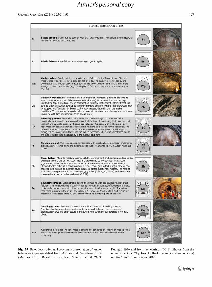
Fig. 25 Brief description and schematic presentation of tunnel
behaviour types (modified from Marinos and Tsiambaos 2010)
(Marinos 2013). Based on data from Schubert et al. 2003,
Terzaghi 1946 and from the Marinos (2013). Photos from the
author except for ‘‘Sq’’ from E. Hoek (personal communication)
and for ‘‘San’’ from Seingre 2005
Geotech Geol Eng (2014) 32:97–130 127
123
Author's personal copy

Fig. 26 Tunnel behaviour chart (TBC): an assessment of rock mass behaviour in tunnelling (modified from Marinos and Tsiambaos 2010)
128 Geotech Geol Eng (2014) 32:97–130
123
Author's personal copy

References
Aksoy CO, Onargan T (2010) The role of umbrella arch and face
bolt as deformation preventing support system in pre-
venting building damages. Tunn Undergr Sp Technol
25:553–559
Attewell PB, Yeates J, Selby AR (1986) Soil movements
induced by tunnelling and their effects on pipelines and
structures. Blackie and Sons Ltd, London
Bizjak K, Petkovsek B (2004) Displacement analysis of tunnel
support in soft rock around a shallow highway tunnel at
Golovec. Eng Geol 75:89–106
Coulter S, Martin CD (2006) Effect of jet-grouting on surface
settlements above the Aeschertunnel, Switzerland. Tunn
Undergr Sp Technol 21:542–553
Croce P, Modoni G, Russo G (2004) Jet-grouting performance
in tunneling. GeoSupport. American Society of Civil
Engineers, Florida
Dywidag-Systems International (2012) DSI info 19. Dywidag-
Systems International. http://www.dywidag-systems.com/
Accessed October 11, 2012
Fang Q, Zang D, Ngai L, Wong Y (2012) Shallow tunnelling
method (STM) for subway station construction in soft
ground. Tunn Undergr Sp Technol 29:10–30
Fasani M, Ammann E, Ruttimann M (2012) Tunnel San Fedele.
Geomech Tunn 5:135–148
Gall V, Rudolf J, O’Brien T (2011) Considerations for very
shallow conventional (SEM) tunneling in urban settings.
Rapid Excavation and Tunneling Conference. San Fran-
cisco, California 1281–1296
Gamsjager H, Scholz M (2009) Pipe roofing—features and
application. 11
Gibbs PW, Lowrie J, Keiffer S, McQueen L (2002) M5 east—
design of a shallow soft ground shotcrete motorway tunnel.
In Proceeding of the 28th ITA-AITES World Tunnelling
Congress, Sydney, Australia
Gioda G, Locatelli L (1999) Back analysis of the measurements
performed during the excavation of a shallow tunnel in
sand. Int J Numer Anal Methods Geomech 23:1407–1425
Gschnitzer R, Goliasch E (2009) TBM modification for chal-
lenging rock conditions—a progress report of the Niagara
Tunnel Project (NTP). Geomech Tunn (Ernst and Sohn
Verlag fur Architektur und technische Wissenschaften
GmbH and Co.) 2:168–178
Harazaki I, Anon H, Matsuda A, Aoki T, Hakoishi Y (1998)
Field observation of large supported by umbrella method:
Case of Maiko Tunnel in Kobe, Japan. Tunneling and
Metropolises, Proceedings of the world tunneling congress,
1009–1014
Hoek E (2007) Practical rock engineering. Rocscience Inc,
North Vancouver
John M, Mattle B (2002) Design of tube umbrella. Mag Czech
Tunn Comm Slovak Tunn Assoc 3
Keller (2013) Keller: ground improvement. Keller: international
geotechnical contractors (2013) http://www.kellerholding.
com/en/services/groundimprovement.html Accessed 04
13, 2013
Kim S (2008) Some experience from the soft ground tunnelling
in urban ground. Seminar on: the state-of-the-art technol-
ogy and experience on geotechnical engineering in Korea
and Hong Kong. Seoul: Geotechnical Division, the Hong
Kong Institution of Engineers, March 28, 2008
Kimura H, Itoh T, Iwata M, Fujimoto K (2005) Application of
new urban tunneling method in Baikoh tunnel excavation.
Tunn Undergr Sp Technol 20:151–158
Leca E, Barry N (2007) Settlements induced by tunneling in Soft
Ground. Tunn. and Undergr. Sp. Technology: 119–149
Liu H, Shou K, Hou P, Tsai C (2010) Design and construction of
river crossing tunnel beneath Tachia River, Taiwan. Tunn
Undergr Sp Technol 25:638–650
Lunardi P (2008) Design and construction of tunnels. Springer,
Berlin Heidelberg
Mager W, Mocivnik J (2000) Modern casing technology sets a
milestone in drilling and ground anchoring. Felsbau 18:43
Marinos VP (2013) Assessing rock mass behaviour for tunnel-
ling. Geoscience, Environ Eng (accepted for publication)
Marinos P, Tsiambaos G (2010) Tunnels under construction in
Greece: tunnel Platanos (In greek). National Technical
University of Athens, Athens
Miura K (2003) Design and construction of mountain tunnels in
Japan. Tunn Undergr Sp Technol 29:115–126
Ocak I (2008) Control of surface settlements with umbrella arch
methods in second stage excavations of Istanbul Metro.
Tunn Undergr Sp Technol 23:674–681
Oke J, Vlachopoulos N, Diederichs M (2012) Sensitivity
numerical analysis of orientations and sizes of Forepoles
for underground excavations in weak rock. American Rock
Mechanics Association, Chicago
Passlick T, Doerendahi K (2006) Quality assurance in jet gro-
uting for a deep seated slab in Amserdam, Keller. http://
www.smet-keller.nl/wp-content/downloads/136.publicatie.
Jetgrouten.Amsterdam%203%20stations.engels.pdf acces-
sed 2012
Peila D, Pelizza S (2003) Ground reinforcing and steel pipe
umbrella system in tunnelling. In: Kolymbas D (ed)
Rational tunneling: advances in geotechnical engineering
and tunnelling. Logos Verlag Berlin, Innsbruck, pp 93–132
Pichler C, Lackner R, Spira Y (2003) Thermochemomechanical
assessment of ground improvement by jet grouting in
tunneling. J Eng Mech 129:951–962
Sadaghiani M, Dadizadeh S (2010) Study on the effect of a new
construction method for a large span metro underground
station in Tabriz-Iran. Tunn Undergr Sp Technol 25:63–69
Schumacher FP, Kim E (2013) Modeling the pip eumbrella roof
support system in aWestern US under ground coal mine. Int
J Rock Mech Min Sci 23:114–124
Shin CB, Chum BS, Park D, Jung JJ (2006) Construction of
double track subway tunnel in the alluvial soils with shal-
low overburden. In: Proceedings of the ITA-AITES 2006
World Tunnel Congress and the 32nd ITA General
Assembly, Seoul, Korea
Song K, Cho G, Sim Y, Lee I (2006) Optimization of a pre-
improvement support system for large underground exca-
vation. Tunn Undergr Sp Technol 21:374
Trinh QN (2006) Analyses of a cave-in problem in a hydro-
power tunnel in Vietnam. Dissertation, Trondheim, Nor-
way: Norwegian University of Science and Technology
Trinh QN, Broch E, Lu M (2007) Three dimensional modelling
of spiling bolts for tunnelling at weakness zones. In: Eb-
erhardt E, Stead D, Morrison T (eds) Rock mechanics:
Geotech Geol Eng (2014) 32:97–130 129
123
Author's personal copy
meeting society’s challenges and demands. Taylar and
Francis, London, pp 427–432
Tuncdemir H, Aksoy CO, Guclu E, Ozer SC (2012) Umbrella
arch and forepoling support methods: a comparison. EU-
ROCK, Stockholm, pp 515–527
Vardakos S (2007) Back-analysis methods for optimal tunnel
design. Dissertation, Blacksburg, Virginia: Virginia Poly-
technic Institute and State University
Vlachopoulos N (2009) Material behaviour and near-face sup-
port issues associated with the tunneling through weak rock
masses. Dissertation, Kingston, Ontario: Queen’s
University
Vlachopoulos N, Diederichs MS (2009) Improved longitudinal
displacement profiles for convergence confinement ana-
lysis of deep tunnels. Rock Mech Rock Eng
42(2):131–146. doi:10.1007/s00603-009-0176-4
Vlachopoulos N, Diederichs MS, Marinos V, Marinos P (2013)
Tunnel behaviour associated with the weak Alpine rock
masses of the Driskos twin tunnel system, Egnatia Odos
Highway. Can Geotech J 50:91–120
Volkmann GM, Schubert W (2006) A contribution to the design
of tunnels supported by a pipe roof. American Rock
Mechanics Association, Golden
Volkmann GM, Schubert W (2007) Geotechnical model for pipe
roof supports in tunneling. In: Proceedings of the 33rd ITA-
AITES world tunneling congress, underground space—the
4th dimension of metropolises. Prague: Taylor and Francis
Group 755–760
Wang H (2012) Optimization of pipe roof reinforcement applied
in tunnel construction under complex conditions. Electron
J Geotech Eng 17:301–310
Warner PE (2004) Practical handbook of grouting. Wiley, New
Jersey
Wittke W, Pierau B, Erichsen C (2006) New austrian tunneling
method (NATM)—stability analysis and design. WBI,
Essen
Yasitli E (2012) Numerical modeling of surface settlements at
the transition zone excavated by New Austrian tunneling
method and umbrella arch method in weak rock. Arab J
Geosci 6:2699–2708
Yeo C, Lee F, Tan S, Hasegawa O (2009) Three dimensional
numerical modelling of a NATM tunnel. Intern J Jpn
Comm Rock Mech 5:33–38
130 Geotech Geol Eng (2014) 32:97–130
123
Author's personal copy