GEOSYNTHETICS APPLICATIONS AND … APPLICATIONS AND PERFORMANCE REVIEWS – SELECT CASE HISTORIES...
17
GEOSYNTHETICS APPLICATIONS AND PERFORMANCE REVIEWS – SELECT CASE HISTORIES Debora J. Miller, P.E., Ph.D. 1 , Dean B. Durkee, P.E., Ph.D. 2 , Michael A. Morrison, P.E. 3 , David B. Wilson, P.E. 4 , and Kevin Smith, P.E 5 Summary The use of geosynthetics in dams continues to be debated among dam engineers. In general, geosynthetics tend to be used with caution in non-critical or redundant applications because of concerns and uncertainties about long-term performance. As experience with geosynthetics in long-term service accumulates, dam engineers continue to re-evaluate the use of various products in specific applications. This paper presents a number of case histories that illustrate a variety of geosynthetic treatments in dams for drainage and as seepage barriers. All applications presented in this paper were designed by the authors and installed under our oversight. The performance of these systems since their installation was reviewed with the dam owners/operators. Performance reviews are summarized and discussed in the paper. Introduction Geosynthetics are widely used and accepted for many diverse applications in earthwork construction, such as liners for landfills and reservoirs, reinforcement for retaining structures and slopes, and for stabilization of soft embankment foundations and in pavement subgrades. In spite of their widespread use for other applications, geosynthetics have been slow to gain acceptance for use in dam construction and repair, especially in the U.S. This is primarily due to concerns about long-term performance, durability, and integrity of critical material properties. This paper documents five case histories in which geosynthetics were used for either seepage control or drainage. We report on the performance to date of these systems based on recent interviews with the project owners, and on monitoring data where available. Nilan East Dam Sinkhole Remediation Project, Montana (1999) General Description of Project The Nilan Project was built in 1951 for agricultural purposes by the Montana State Water Conservation Board (currently the Montana Department of Natural Resources and Conservation (MDNRC)). Nilan Reservoir is an off-stream reservoir located approximately eight miles west of Augusta, Montana, along the eastern slope of the Rocky Mountains. The project consists of two dams and several miles of supply and delivery canals. The reservoir site is situated in a glacial 1 Manager Earth Science and Hydraulics, Gannett Fleming, Inc., Windsor, CO 2 Manager Earth Science and Hydraulics, Gannett Fleming, Inc., Phoenix, AZ 3 Project Manager, Dams & Flood Control Section, Gannett Fleming, Inc., Harrisburg, PA 4 Manager, Geotechnical Section, Gannett Fleming, Inc., Harrisburg, PA 5 Chief, State Water Projects Bureau, Montana Dept. Natural Resources and Conservation, Helena, MT
Transcript of GEOSYNTHETICS APPLICATIONS AND … APPLICATIONS AND PERFORMANCE REVIEWS – SELECT CASE HISTORIES...

GEOSYNTHETICS APPLICATIONS AND PERFORMANCE REVIEWS – SELECT CASE HISTORIES
Debora J. Miller, P.E., Ph.D. 1, Dean B. Durkee, P.E., Ph.D.2, Michael A. Morrison, P.E.3,
David B. Wilson, P.E. 4, and Kevin Smith, P.E 5
Summary
The use of geosynthetics in dams continues to be debated among dam engineers. In general, geosynthetics tend to be used with caution in non-critical or redundant applications because of concerns and uncertainties about long-term performance. As experience with geosynthetics in long-term service accumulates, dam engineers continue to re-evaluate the use of various products in specific applications. This paper presents a number of case histories that illustrate a variety of geosynthetic treatments in dams for drainage and as seepage barriers. All applications presented in this paper were designed by the authors and installed under our oversight. The performance of these systems since their installation was reviewed with the dam owners/operators. Performance reviews are summarized and discussed in the paper.
Introduction
Geosynthetics are widely used and accepted for many diverse applications in earthwork
construction, such as liners for landfills and reservoirs, reinforcement for retaining structures and slopes, and for stabilization of soft embankment foundations and in pavement subgrades. In spite of their widespread use for other applications, geosynthetics have been slow to gain acceptance for use in dam construction and repair, especially in the U.S. This is primarily due to concerns about long-term performance, durability, and integrity of critical material properties. This paper documents five case histories in which geosynthetics were used for either seepage control or drainage. We report on the performance to date of these systems based on recent interviews with the project owners, and on monitoring data where available.
Nilan East Dam Sinkhole Remediation Project, Montana (1999) General Description of Project
The Nilan Project was built in 1951 for agricultural purposes by the Montana State Water Conservation Board (currently the Montana Department of Natural Resources and Conservation (MDNRC)). Nilan Reservoir is an off-stream reservoir located approximately eight miles west of Augusta, Montana, along the eastern slope of the Rocky Mountains. The project consists of two dams and several miles of supply and delivery canals. The reservoir site is situated in a glacial
1Manager Earth Science and Hydraulics, Gannett Fleming, Inc., Windsor, CO 2Manager Earth Science and Hydraulics, Gannett Fleming, Inc., Phoenix, AZ 3Project Manager, Dams & Flood Control Section, Gannett Fleming, Inc., Harrisburg, PA 4Manager, Geotechnical Section, Gannett Fleming, Inc., Harrisburg, PA 5Chief, State Water Projects Bureau, Montana Dept. Natural Resources and Conservation, Helena, MT

formation characterized as “knob and kettle” terrain. The dams were constructed on the north and east sides of a major “kettle” or “pothole” feature, raising the water level of a natural lake to form a 10,100 acre-foot water supply reservoir. These dams are referred to, respectively, as the Nilan North Dam and Nilan East Dam. The dams are 50 to 55 feet high, homogeneous earthen embankments, with shallow cutoff trenches into the underlying deep glacial till foundations. This section describes repairs to the reservoir side of the Nilan East Dam that utilized woven geotextile and geosynthetic clay liner (GCL) materials to remediate sinkholes that appeared in 1999 near the upstream toe of the dam.
Piping Issues at Nilan East Dam
In early April 1999, during an annual inspection, a depression was found in native foundation materials just above the reservoir pool and immediately adjacent to the upstream right toe of the dam. The general shape of the depression was described as a slanted “L” with both legs about 8 feet long and 2 to 4 feet wide. The total depth of the depression ranged from 0.5 to 1.8 feet. At the time of the inspection there were no monitoring wells on this dam. There was no evidence of any excess seepage or transported materials downstream from the dam.
The MDNRC hired a geotechnical consulting firm (ESA Consultants of Bozeman, Montana) to perform subsurface investigations and provide recommendations for emergency remediation as needed. The investigation and design were conducted under the direction of the lead author of this paper (who was the project manager for ESA Consultants at the time) and co-author Kevin Smith (project engineer at the time for MDNRC). The initial investigation consisted of 7 borings and several test pits. Vertically nested piezometers were installed in all borings. The piezometer data indicated a strong downward hydraulic gradient (sink) in the downstream right abutment of the dam, opposite the location of the upstream sinkhole feature.
The drilling investigation revealed that the glacial materials underlying the East Dam generally consist of very low permeability clayey sands and gravels near the ground surface, underlain by intermixed gravels, cobbles, and boulders extending to a depth of about 60 to 70 feet below the base of the dam. The low-permeability materials at the ground surface essentially comprise a natural reservoir “liner”. Underlying the intermixed surficial materials at depths of 60 to 70 feet under the East Dam is a very permeable, 20 to 30 foot thick zone of clean sand and gravels. The deeper permeable zone was interpreted as a fluvial outwash deposit.
Test pit investigations in the immediate vicinity of the depression found several deep erosion “piping” features that had formed in the surficial, fine-grained materials, some up to 12-inches in diameter (Figure 1). These pipes appeared to trend vertically downward.
Depressions and piping features
Figure 1. Surface Depressions and Vertical Piping Features at Nilan East Dam
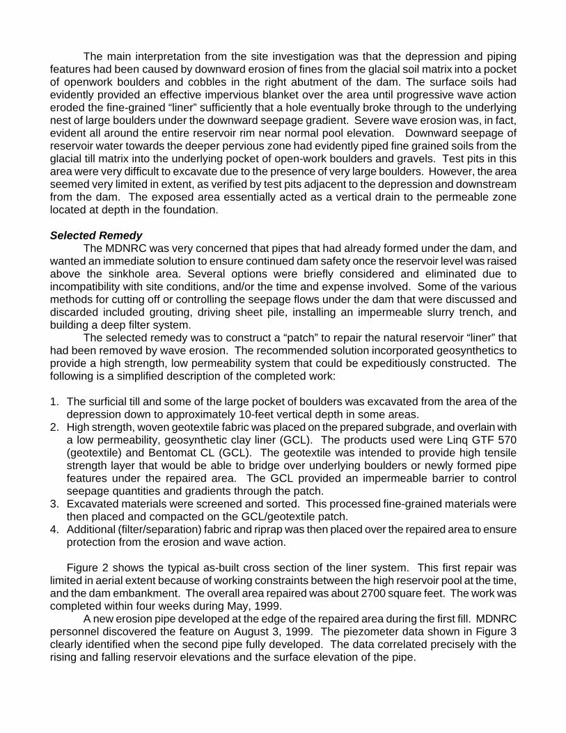
The main interpretation from the site investigation was that the depression and piping features had been caused by downward erosion of fines from the glacial soil matrix into a pocket of openwork boulders and cobbles in the right abutment of the dam. The surface soils had evidently provided an effective impervious blanket over the area until progressive wave action eroded the fine-grained “liner” sufficiently that a hole eventually broke through to the underlying nest of large boulders under the downward seepage gradient. Severe wave erosion was, in fact, evident all around the entire reservoir rim near normal pool elevation. Downward seepage of reservoir water towards the deeper pervious zone had evidently piped fine grained soils from the glacial till matrix into the underlying pocket of open-work boulders and gravels. Test pits in this area were very difficult to excavate due to the presence of very large boulders. However, the area seemed very limited in extent, as verified by test pits adjacent to the depression and downstream from the dam. The exposed area essentially acted as a vertical drain to the permeable zone located at depth in the foundation. Selected Remedy
The MDNRC was very concerned that pipes that had already formed under the dam, and wanted an immediate solution to ensure continued dam safety once the reservoir level was raised above the sinkhole area. Several options were briefly considered and eliminated due to incompatibility with site conditions, and/or the time and expense involved. Some of the various methods for cutting off or controlling the seepage flows under the dam that were discussed and discarded included grouting, driving sheet pile, installing an impermeable slurry trench, and building a deep filter system.
The selected remedy was to construct a “patch” to repair the natural reservoir “liner” that had been removed by wave erosion. The recommended solution incorporated geosynthetics to provide a high strength, low permeability system that could be expeditiously constructed. The following is a simplified description of the completed work:
1. The surficial till and some of the large pocket of boulders was excavated from the area of the
depression down to approximately 10-feet vertical depth in some areas. 2. High strength, woven geotextile fabric was placed on the prepared subgrade, and overlain with
a low permeability, geosynthetic clay liner (GCL). The products used were Linq GTF 570 (geotextile) and Bentomat CL (GCL). The geotextile was intended to provide high tensile strength layer that would be able to bridge over underlying boulders or newly formed pipe features under the repaired area. The GCL provided an impermeable barrier to control seepage quantities and gradients through the patch.
3. Excavated materials were screened and sorted. This processed fine-grained materials were then placed and compacted on the GCL/geotextile patch.
4. Additional (filter/separation) fabric and riprap was then placed over the repaired area to ensure protection from the erosion and wave action.
Figure 2 shows the typical as-built cross section of the liner system. This first repair was
limited in aerial extent because of working constraints between the high reservoir pool at the time, and the dam embankment. The overall area repaired was about 2700 square feet. The work was completed within four weeks during May, 1999.
A new erosion pipe developed at the edge of the repaired area during the first fill. MDNRC personnel discovered the feature on August 3, 1999. The piezometer data shown in Figure 3 clearly identified when the second pipe fully developed. The data correlated precisely with the rising and falling reservoir elevations and the surface elevation of the pipe.
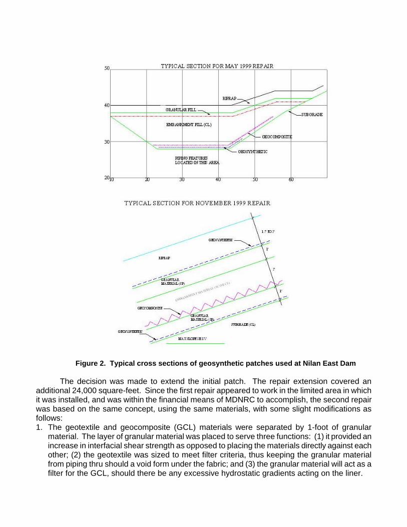
Figure 2. Typical cross sections of geosynthetic patches used at Nilan East Dam The decision was made to extend the initial patch. The repair extension covered an
additional 24,000 square-feet. Since the first repair appeared to work in the limited area in which it was installed, and was within the financial means of MDNRC to accomplish, the second repair was based on the same concept, using the same materials, with some slight modifications as follows: 1. The geotextile and geocomposite (GCL) materials were separated by 1-foot of granular
material. The layer of granular material was placed to serve three functions: (1) it provided an increase in interfacial shear strength as opposed to placing the materials directly against each other; (2) the geotextile was sized to meet filter criteria, thus keeping the granular material from piping thru should a void form under the fabric; and (3) the granular material will act as a filter for the GCL, should there be any excessive hydrostatic gradients acting on the liner.
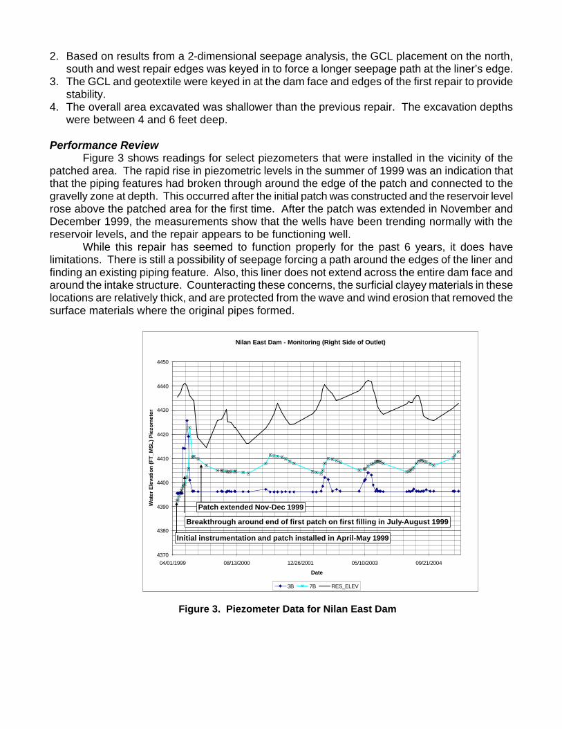
Nilan East Dam - Monitoring (Right Side of Outlet)
4370
4380
4390
4400
4410
4420
4430
4440
4450
04/01/1999 08/13/2000 12/26/2001 05/10/2003 09/21/2004
Date
Wat
er E
leva
tion
(F
T_M
SL
) P
iezo
met
ers
3B 7B RES_ELEV
Initial instrumentation and patch installed in April-May 1999
Breakthrough around end of first patch on first filling in July-August 1999
Patch extended Nov-Dec 1999
2. Based on results from a 2-dimensional seepage analysis, the GCL placement on the north, south and west repair edges was keyed in to force a longer seepage path at the liner’s edge.
3. The GCL and geotextile were keyed in at the dam face and edges of the first repair to provide stability.
4. The overall area excavated was shallower than the previous repair. The excavation depths were between 4 and 6 feet deep.
Performance Review
Figure 3 shows readings for select piezometers that were installed in the vicinity of the patched area. The rapid rise in piezometric levels in the summer of 1999 was an indication that that the piping features had broken through around the edge of the patch and connected to the gravelly zone at depth. This occurred after the initial patch was constructed and the reservoir level rose above the patched area for the first time. After the patch was extended in November and December 1999, the measurements show that the wells have been trending normally with the reservoir levels, and the repair appears to be functioning well.
While this repair has seemed to function properly for the past 6 years, it does have limitations. There is still a possibility of seepage forcing a path around the edges of the liner and finding an existing piping feature. Also, this liner does not extend across the entire dam face and around the intake structure. Counteracting these concerns, the surficial clayey materials in these locations are relatively thick, and are protected from the wave and wind erosion that removed the surface materials where the original pipes formed.
Figure 3. Piezometer Data for Nilan East Dam

Gardner Creek Dam Modifications, Pennsylvania (1983) General Description of the Project
Gardner Creek Dam is a 44-foot-high earth embankment dam located on Gardner Creek in Luzerne County, Pennsylvania. The dam embankment includes a masonry core wall that extends to a hardpan foundation at a depth of approximately 16 feet below the toe elevation. The dam’s principal spillway is a concrete chute; the auxiliary spillway is a gabion-lined trapezoidal channel.
The dam was originally constructed between 1898 and 1902. Modifications to increase the spillway capacity were constructed in 1930 and in 1983. The 1983 modifications included a replacement of the principal spillway, construction of an auxiliary spillway, and raising the embankment crest elevation by four feet.
The June 1978 Phase I Inspection Report noted that the core wall appeared to be functioning adequately, as no significant amounts of seepage had been observed on the downstream slope or toe of the dam (1). However, the Phase I Report and previous observation records noted a persistent wet area in the vicinity at the embankment toe near the twin 20-inch-diameter cast iron outlet works pipes. It was also reported that upstream closure facilities were not available at the dam, and that the outlet works pipes passing through the embankment were operating under full reservoir head at all times. No information was available as to the condition of the outlet works pipes, and it was speculated that the wet area might have been related to a leak from the outlet works pipes or a weak area in the core wall at the outlet works pipe penetrations. Severe displacement of the spillway sidewalls also was observed. Most of this displacement was horizontal and could be observed along horizontal cracks that had formed in the lower portions of the spillway sidewalls.
The 1983 embankment raising was accomplished by stripping the downstream slope to a depth of 12 inches and placing zoned fill on the downstream slope of the dam (Figure 4). The fill at the toe of the dam consisted of rock fill that was encased at the top, bottom, and existing dam surface by filter fabric and a gravel filter layer. Filter fabric and gravel filter was also placed on top of the outlet works pipes at the location of the reconstructed valve vault. A trench drain with filter fabric, gravel backfill, and a perforated concrete pipe was installed along the toe of the rock fill. The filter fabric, drain, and rock fill installation was constructed to intercept any embankment seepage and to convey any leakage from the outlet works pipes that might have been occurring at the valve structure. Filter fabric was also used to encase gravel and rockfill blanket drains that were designed to limit hydrostatic loads on the spillway walls (Figure 5).
Figure 4. Gardner Creek Dam Embankment Raise Section, Showing Filter Fabric Installation

Figure 5. Gardner Creek Dam, Section Through Spillway Walls Performance Review
To evaluate the performance of the filter fabric, notes from recently completed dam inspection reports were compared to the purposes for which the filter fabric was installed. These purposes were as follows:
1. To prevent the loss of embankment material (internal erosion) caused by seepage that might be occurring through the embankment.
2. To limit hydrostatic loads on the spillway walls. 3. To prevent the movement of fill material placed above the rockfill toe into the rockfill.
Records of annual inspections at the dam (1, 2) do not include any observations of discharges from the trench drain that was constructed at the toe of the rock fill. Construction drawings (3) show the drain outlet location at the right side of the spillway channel, but drain discharges have not been mentioned in any of the field inspection reports to date. However, a minor seep has been observed in close proximity to the blowoff pipe outlet. The observed seepage has been clear. This suggests that seepage has been occurring and continues to occur along the outlet works pipelines. The trench drain located along the perimeter of the rockfill was not designed to intercept seepage that occurred along the outlet works pipelines. Piezometer records collected in 2003 (4) show that piezometric levels within the embankment near the cutoff wall are near the bottom of the blanket drain. This may explain the lack of drain discharge observations.
Since the replacement spillway has been constructed, no horizontal movement or leaning in the walls has been observed. Minor vertical settlement has been observed, but appears to have occurred primarily within the first five years after construction of the replacement spillway. No new settlement has been observed. Discharges from spillway wall weep holes have not been observed.
Inspection records show that small depressions have formed next to concrete retaining walls in areas where earthen fill was placed on top of filter fabric and rock fill. Exposed filter fabric has been observed at the bottom of these depressions. It is possible that ruptures in the fabric may have occurred in these areas or that earthen materials have flowed through a gap between

the filter fabric and the concrete wall. It is noted that the areas where these depressions have been observed are close to weep holes in the walls. The weep holes are covered on both sides by rock fill, so discharges from the weep holes cannot be observed.
Lynchwood Lake Dam, Pennsylvania (1990-1991)
General Description of the Project
Lynchwood Lake Dam near Mount Pocono, Pennsylvania, is a 23-foot-high, 1,600-foot-long timber crib and earthfill dam that was constructed in the late 1800’s. Its original purpose was for ice farming, as the reservoir was situated near a rail line for refrigeration cars, and was later was used as a recreation lake for a girls summer camp. Gannett Fleming designed repairs for the dam between 1990 and 1991, including refurbishments for the low-level outlet and principal spillway, and an upstream seepage control blanket for a portion of the embankment that was experiencing excessive seepage resulting in reservoir losses (Figure 6).
The upstream seepage blanket was a unique application of geotextile in an upstream
seepage control function. The design employed a heavy, nonwoven geotextile, laid directly over exposed timber crib/rockfill materials, followed by placement of a locally obtained semi-pervious fill on the upstream side (Figure 6). The fabric, which was a grade normally used for railroad subgrade/ballast separation, was sufficiently robust to withstand the extreme installation conditions, and the opening size was specifically designed to clog with the fine-grained materials placed over the fabric, rather than act as a filter. This system provided a cost-effective, relatively impervious barrier which had sufficient strength and flexibility to span large openings in the face of the existing dam, as well as accommodate any ongoing movements of the structure. Performance Review
In preparing this paper, Gannett Fleming contacted the Pennsylvania Department of Environmental Protection (PADEP) Dam Safety chief. We learned that the dam is still in service, but that ownership has changed hands since Gannett Fleming’s involvement on the project. Additional spillway repair work was constructed in August 2001. Although the structure is still subject to periodic inspections, the PADEP chief did not have specific information on how the embankment and the upstream geotextile lining were performing. The dam is evidently still holding water, indicating that the upstream facing is functioning as intended.
It is worth noting that PADEP does not allow the use of geosynthetics internally in an embankment dam as a drain. As do most state dam safety organizations, PADEP does allow geosynthetic use in accessible locations such as toe drains, and as a separator layer between fill materials. PADEP had considered Lynchwood as a unique case, since the fabric was designed to clog to reduce seepage, unlike the traditional use of geosynthetics as filter/drainage elements in dams.
Figure 6. Installation of upstream geotextile seepage barrier

Tongue River Dam Rehabilitation Project, Montana (1999) General Description of Project
Tongue River Dam is located in southern Montana about 10 miles north of the Montana/Wyoming border. The 91 feet high, zoned embankment dam was constructed in the late 1930’s. The Tongue River Basin Project was a $50 million dam safety rehabilitation project constructed between 1995 and 1999, which included a new RCC emergency spillway over the dam, a new labyrinth-weir primary spillway in the left abutment, and a new outlet works. The main elements of the project are shown on Figure 7. In April 1998, as fill was being removed in conjunction with demolition of the old spillway, a large void was discovered in the clay core of the dam (Figure 8). The cavity was about 12 feet in diameter and 50 feet long, oriented roughly parallel with the dam axis. The void had formed by piping and internal erosion of clay fill that had been placed directly against intensely fractured bedrock, known as the Clinker Unit, in the dam abutment. Previous papers describe the detailed history of seepage and erosion at the dam (5), and the expedited design and construction of remedial measures to control seepage and prevent future erosion of the clay fill in the vulnerable abutment area (6). The selected remedy was a combination of driven, joint-sealed steel sheet piling and geosynthetic seepage barriers to minimize seepage, plus partial removal and replacement of the dam crest to incorporate internal granular filters. This paper focuses on the geosynthetic seepage barriers that were installed, and the performance review of these barriers based on piezometric data.
Figure 7. Tongue River Basin Project Elements
Location of Void Found in April 1998

Figure 8. Erosion cavity found at fractured rock interface at Tongue River Dam Components of the Seepage Cutoff System
The selected remediation concept was to minimize seepage in the vulnerable areas where the fractured rock/clay core contact was unprotected. Seepage at the core/fractured rock contact was minimized using a positive cutoff system comprising a combination of vertical and horizontal seepage barriers. The vertical barrier was a driven, joint-sealed sheet pile wall. The horizontal barriers utilized geomembranes and geosynthetic clay liners (GCLs) that were placed to provide a positive lateral connection between the vertical sheet pile barrier and the spillway structure, and to deflect and reduce seepage flows that overtop the vertical barriers east and west of the spillway. Textured 40 mil, polyethylene geomembrane material was used in front of the spillway, extending partway under the toe of the west closure dam. The geomembrane was underlain by GCL, except in the closure dam area because of slope stability concerns. Geomembrane was selected because of its very low hydraulic conductivity, and the ability to make a relatively water-tight batten connection of this material to the concrete footings and slabs on the spillway structure. The underlying GCL provides a second line of defense in case of geomembrane damage or separation from the structure. GCL also was used east of the right spillway wall (as shown on Figure 9) and at a higher level within the closure dam. GCL was selected for these less critical areas primarily because of its lower cost. More detailed descriptions and drawings of the the remediation design elements are presented in the 2001 ASDSO conference proceedings (6).
Void location
Fractured rock (Clinker Unit) Clay
Core
Old Gate House

Figure 9. Typical section of cutoff system on right side of primary spillway
The sheet piling was driven completely through the abutment core trench and toed into a tight siltstone unit that underlies the fractured Clinker Unit across the front of the primary spillway, under the west closure dam, and into the far left abutment about 800 feet around the reservoir rim. This pile driving depth criteria was also maintained to the extent possible beyond the right limits of the spillway (towards the dam), as illustrated on Figure 9. However, moving further towards the valley section of the dam from the abutment, the clay core trench broadens and deepens significantly as it cuts off the deep alluvial materials in the Tongue River Valley. The decision was made to stop the pile driving depth above the bedrock, toeing in within the deeper core trench at an elevation below the base of the Clinker Unit. This criteria was a compromise between excavation costs and pile driving depth limitations. Seepage analyses were used to estimate exit gradients at the clay core/fractured rock interface in order to define the required lateral extent of the barrier system into the dam section. Figure 10 illustrates the seepage analyses that were used to guide the lateral extent of the seepage barriers for this end condition.
Clay core/fractured rock interface
Figure 10. Seepage analysis to define lateral extent of seepage barrier system into dam section

Performance Review
Figure 11 shows the location of the sheet pile alignment and piezometers that were installed to monitor the performance of the barrier system. Current piezometer designations are shown in parenthesis. This discussion will focus on piezometers left of the spillway (402, 403 and 404) and right of the spillway (405 through 409).
Figure 12 shows the data plots for piezometers left of the spillway. The interpretation of
these data are as follows:
• 401 – located on the crest of the west closure dam (crest elevation 3442.5). This piezometer is an open standpipe with the perforated zone completed in clay fill at elevation 3426.1, above the horizontal GCL barrier. Water elevations in this well are consistently above the reservoir levels, which is very perplexing. The MDNRC has tried bailing the standpipe, but water levels quickly return to high readings.
• 402 – located beneath the upstream slope of the west closure dam. This is a vibrating wire piezometer embedded in clay fill just above the clinker unit contact at elevation 3403.4, beneath the horizontal geomembrane barrier. Pore pressures have remained negative, indicating unsaturated conditions under the barrier at this location.
• 403 - located in the clay-filled core trench upstream from the spillway and downstream from the sheet pile wall, beneath the GCL/geomembrane liner. This is a vibrating wire piezometer embedded near the base of the core trench at elevation 3388.1 in clay fill adjacent to the clinker unit contact. This piezometer appears to be responding to pore pressures in the clinker unit downgradient from the cutoff system. The interpretation is that the clinker unit, which is an intensely fractured rock mass, “fills up” like a drain fed from the exposure of the unit on the reservoir rim west of the barrier. The rapid and extreme rise and fall of pore pressures likely corresponds to filling and drainage of the clinker unit in response to reservoir fluctuations.
• 404 – located in the clay-filled core trench upstream from the sheet pile wall. This is a vibrating wire piezometer embedded at elevation 3388.3 in clay fill adjacent to the clinker unit contact on the upstream side of the core trench. This piezometer closely tracks the reservoir elevations.
Figure 11. Locations of piezometers in left abutment of Tongue River Dam

Tongue River Dam - Piezometers Left Side of Spillway
3380
3390
3400
3410
3420
3430
3440
01/01/00 07/19/00 02/04/01 08/23/01 03/11/02 09/27/02 04/15/03 11/01/03 05/19/04 12/05/04
Date
Wat
er E
leva
tion
(FT_
MS
L)
402-VW 403-VW 404-VW 401 well RES_ELEV
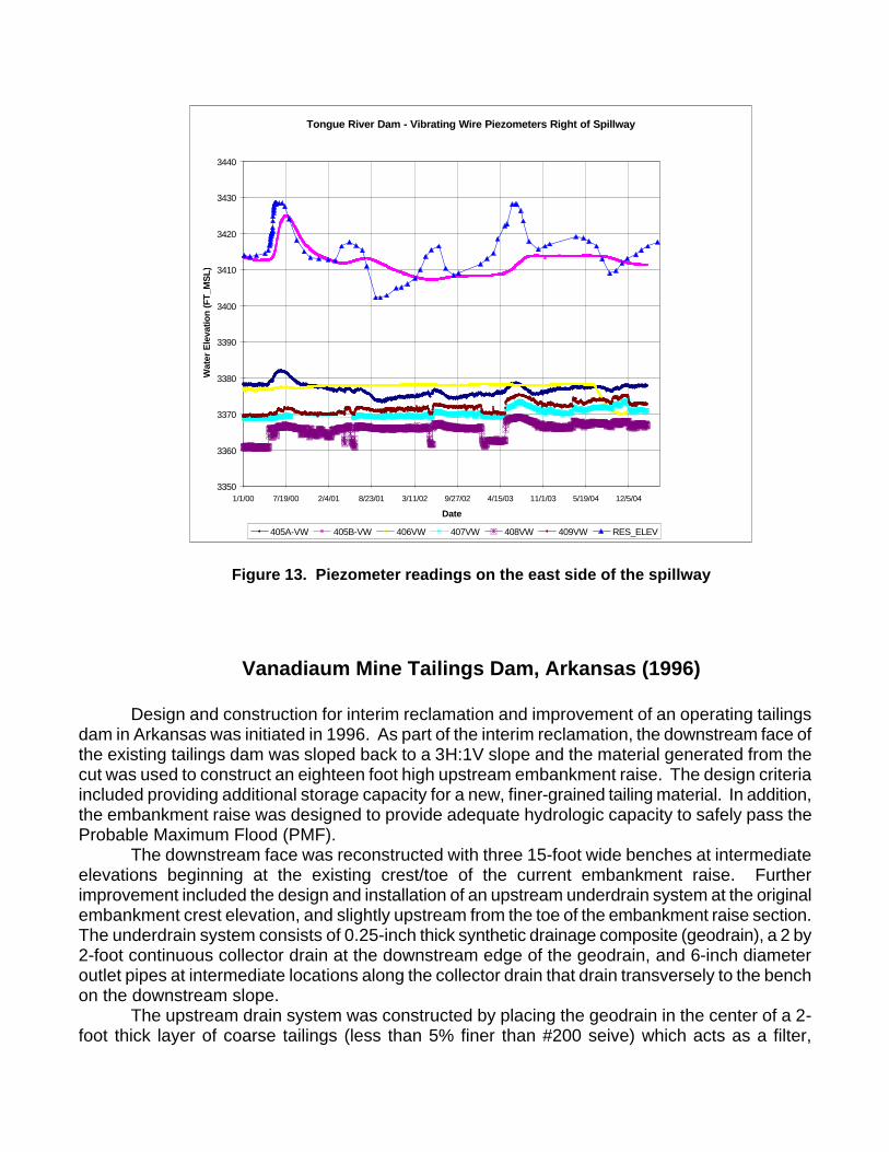
Figure 12. Piezometer readings on the west side of the spillway Figure 13 shows piezometer readings for instruments located on the east side of the
spillway. The interpretation of these data is as follows:
• 405A – located in the clay core trench near the upstream toe of the sheet pile. The sheet pile at this location is toed into the clay fill above the siltsone bedrock (see Figure 10). This instrument is a vibrating wire piezometer embedded in clay core fill at elevation 3369.6, below the elevation of the clinker/siltstone contact. Piezometric readings indicate subdued response to reservoir levels and substantial head loss and downward gradient through the core, when compared to the shallower instrument 405B.
• 405B – located in the clay core trench upstream from the sheet pile and above 405A at elevation 3400.0. Readings indicate pore pressures are generally near reservoir elevations, but that these pore pressures do not completely dissipate or rise to full reservoir levels as the reservoir fluctuates.
• 406 – located in the core trench downstream from the sheet pile wall, above the toe of the pile, and beneath the GCL barrier. This piezometer is situated in clay fill at elevation 3378.6, near the contact between the clinker and siltstone units. This instrument appeared to be non-responsive after its installation in 1999 through about July 2004, when the readings began to drop to elevations below the elevation of the instrument (indicating negative pore pressures).
• 407, 408 and 409 – located in the core of the main dam section, downstream from the sheet pile, and east of the easternmost buried contact limits of the core/fractured rock interface. These piezometers reflect significant head loss is occurring across the broad clay core and very subdued response to reservoir level fluctuations.
Tongue River Dam - Vibrating Wire Piezometers Right of Spillway
3350
3360
3370
3380
3390
3400
3410
3420
3430
3440
1/1/00 7/19/00 2/4/01 8/23/01 3/11/02 9/27/02 4/15/03 11/1/03 5/19/04 12/5/04
Date
Wat
er E
leva
tion
(FT_
MS
L)
405A-VW 405B-VW 406VW 407VW 408VW 409VW RES_ELEV
Figure 13. Piezometer readings on the east side of the spillway
Vanadiaum Mine Tailings Dam, Arkansas (1996)
Design and construction for interim reclamation and improvement of an operating tailings dam in Arkansas was initiated in 1996. As part of the interim reclamation, the downstream face of the existing tailings dam was sloped back to a 3H:1V slope and the material generated from the cut was used to construct an eighteen foot high upstream embankment raise. The design criteria included providing additional storage capacity for a new, finer-grained tailing material. In addition, the embankment raise was designed to provide adequate hydrologic capacity to safely pass the Probable Maximum Flood (PMF).
The downstream face was reconstructed with three 15-foot wide benches at intermediate elevations beginning at the existing crest/toe of the current embankment raise. Further improvement included the design and installation of an upstream underdrain system at the original embankment crest elevation, and slightly upstream from the toe of the embankment raise section. The underdrain system consists of 0.25-inch thick synthetic drainage composite (geodrain), a 2 by 2-foot continuous collector drain at the downstream edge of the geodrain, and 6-inch diameter outlet pipes at intermediate locations along the collector drain that drain transversely to the bench on the downstream slope.
The upstream drain system was constructed by placing the geodrain in the center of a 2-foot thick layer of coarse tailings (less than 5% finer than #200 seive) which acts as a filter,
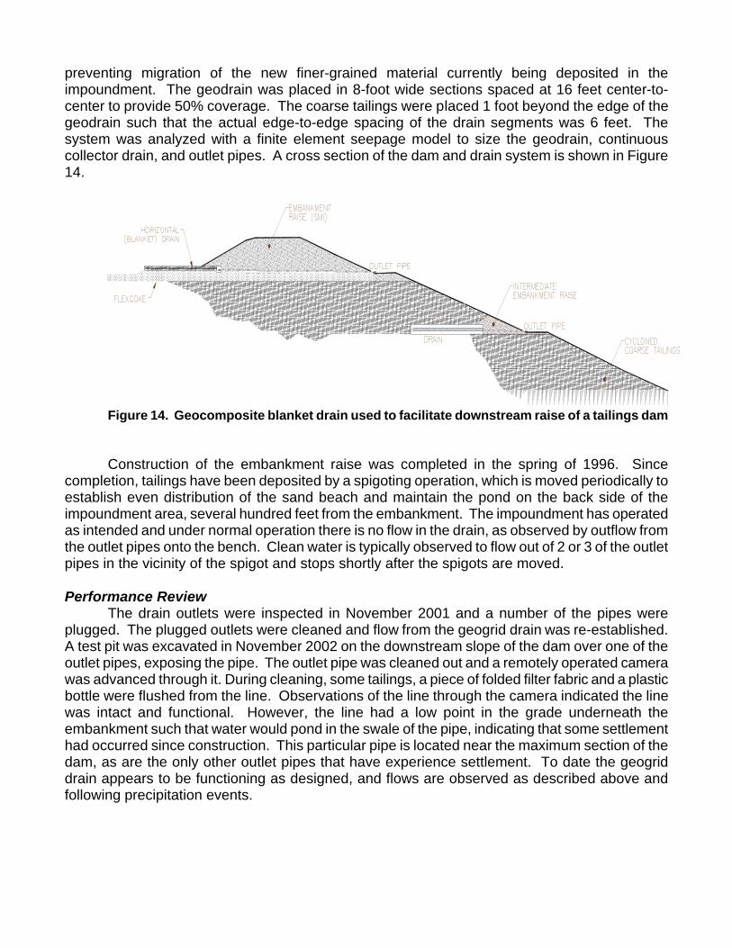
preventing migration of the new finer-grained material currently being deposited in the impoundment. The geodrain was placed in 8-foot wide sections spaced at 16 feet center-to-center to provide 50% coverage. The coarse tailings were placed 1 foot beyond the edge of the geodrain such that the actual edge-to-edge spacing of the drain segments was 6 feet. The system was analyzed with a finite element seepage model to size the geodrain, continuous collector drain, and outlet pipes. A cross section of the dam and drain system is shown in Figure 14.
Figure 14. Geocomposite blanket drain used to facilitate downstream raise of a tailings dam Construction of the embankment raise was completed in the spring of 1996. Since
completion, tailings have been deposited by a spigoting operation, which is moved periodically to establish even distribution of the sand beach and maintain the pond on the back side of the impoundment area, several hundred feet from the embankment. The impoundment has operated as intended and under normal operation there is no flow in the drain, as observed by outflow from the outlet pipes onto the bench. Clean water is typically observed to flow out of 2 or 3 of the outlet pipes in the vicinity of the spigot and stops shortly after the spigots are moved. Performance Review
The drain outlets were inspected in November 2001 and a number of the pipes were plugged. The plugged outlets were cleaned and flow from the geogrid drain was re-established. A test pit was excavated in November 2002 on the downstream slope of the dam over one of the outlet pipes, exposing the pipe. The outlet pipe was cleaned out and a remotely operated camera was advanced through it. During cleaning, some tailings, a piece of folded filter fabric and a plastic bottle were flushed from the line. Observations of the line through the camera indicated the line was intact and functional. However, the line had a low point in the grade underneath the embankment such that water would pond in the swale of the pipe, indicating that some settlement had occurred since construction. This particular pipe is located near the maximum section of the dam, as are the only other outlet pipes that have experience settlement. To date the geogrid drain appears to be functioning as designed, and flows are observed as described above and following precipitation events.
Summary and Conclusions Five examples of the use of geosynthetics in embankment dams are presented in this paper. Three case histories of upstream seepage control systems are described:
• At Nilan East Dam in Montana, low permeability GCL was used in combination with high strength, woven geotextile to patch a sinkhole that had developed by downward seepage erosion through a breach in the natural reservoir lining.
• Textured geomembrane and GCL were used at Tongue River Dam, Montana, in combination with a sheet pile wall vertical seepage barrier, to reduce seepage and exit gradients at the buried abutment contact between clay core material and intensely fracture bedrock.
• A heavy geotextile fabric, designed to clog with the fine soil material placed over it, was used to control seepage at Lynchwood Lake, a leaky timber crib dam in Pennsylvania.
The Nilan East and Tongue River projects were constructed in 1999, and have therefore been in service for about 6 years. Lynchwood Lake remediation was completed in 1991, and is therefore over 15 years in service. All three of these seepage control systems appear to be functioning adequately, although the piezometric data at Tongue River Dam are somewhat inconclusive with regard to the barrier performance, and additional or replacement instruments may be required. Two case histories illustrating the use of geosynthetic in filter and drainage functions are described:
• At Gardner Creek Dam in Pennsylvania, geotextile was used as the downstream filter layer beneath a rockfill zone that was added to construct a downstream raise of the embankment, and filter fabric was also used to encase backfill drain zones behind the spillway walls.
• A geocomposite drain was used to as a critical blanket drainage system to construct an upstream raise of a tailings dam in Arkansas.
The filter fabric at Gardner Creek Dam has been in service since 1983, and appears to be functioning well in the toe berm application. There have been some problems noted in the backfill areas behind the spillway walls at Gardner Creek, but these may be due to settlement of the backfill and not failure of the filter fabric. The geocomposite drain system at the tailings dam continues to operate well, although the pipe outlet components have required periodic cleanout maintenance. These examples illustrate the variety of geosynthetic materials and their potential applications for remediating aging dam problems, or facilitating dam construction or modifications. These examples also underscore the importance of adequate monitoring following installation of these systems to allow evaluation of their performance. As our experience with these products accumulates, the dam engineering community should continue to follow-up and document performance reviews.
References
1. Phase I Inspection Report, Gardner Creek Dam, National Dam Inspection Program, by
Gannett Fleming Corddry and Carpenter, Inc. for the U.S. Army Corps of Engineers, Baltimore District, June 1978.

2. Phase II Investigation Report, Gardner Creek Dam, Gannett Fleming Corddry and Carpenter, Inc., for Pennsylvania Gas and Water Company, November 18, 1981.
3. Construction Drawings, Gardner Creek Dam, Gannett Fleming Water Resources Engineers, Inc., April 1983.
4. Instrument Readings from Pennsylvania-American Water Company, 2003. 5. Miller, D.J., Smith, K., and Volpe, R.L. (1999). Piping and Internal Erosion Control
Measures at Tongue River Dam, Montana, Dealing with Aging Dams, Nineteenth Annual USCOLD Lecture Series, Atlanta Georgia, May 17-21, United States Committee on Large Dams, Denver, Colorado, pp. 443-458.
6. Miller, D.J., Jewell, A.C., and Smith, K. (2001). “Piping and internal erosion control measures at Tongue River Dam,” Proc. Assoc. State Dam Safety Officials, Snowbird, UT, Sept.