Georgia Department of Transportation Incidental Items.pdf617 Permanent Anchored Walls 620 Temporary...
118
Georgia Department of Transportation Construction Engineering Inspection Training Incidental Items—Group 3
Transcript of Georgia Department of Transportation Incidental Items.pdf617 Permanent Anchored Walls 620 Temporary...

Georgia Department of Transportation
Construction Engineering Inspection Training
Incidental Items—Group 3

Table of Contents
581 Pot Bearing
600 Controlled Low Strength Flowable Fill
603 Rip Rap
607 Rubble Masonry
608 Brick Masonry
609 Removal of Portland Cement Concrete Roadway Slabs
610 Removal of Miscellaneous Roadway Items
611 Relaying, Reconstructing or Adjusting to Grade of Miscellaneous Roadway Structures
612 Construct Maintain and Remove Median Crossover
613 Docks
615 Jacking or Boring Pipe
617 Permanent Anchored Walls
620 Temporary Barrier
621 Concrete Barrier
623 Pneumatically Applied Concrete
624 Sound Barriers
626 Mechanically Stabilized Embankment Retaining Walls
627 Mechanically Stabilized Embankment Retaining Wall – Contractor Design
632 Portable Changeable Message Signs
634 Monuments and Road Markers
635 Barricades
636 Highway Signs
637 Illuminated Sign System
638 Structural Supports for Overhead Signs
639 Strain Polls for Overhead Sign and Signal Assemblies
640 Retroreflectorized Railroad Cross Buck Sign
641 Guardrail
643 Fence
645 Repair of Galvanized Coatings
647 Traffic Signal Installation
648 Traffic Impact Attenuator
649 Concrete Glare Screen
651 Raised Traffic Bars
652 Painting Traffic Stripe
653 Thermoplastic Traffic Stripe
654 Raised Pavement Markers
655 Pavement Arrow with Raised Reflectors
656 Removal of Pavement Markings
657 Preformed Plastic Pavement Markings
658 Polyurea Traffic Stripe
659 Hot Applied Preformed Plastic Pavement Markings
666 Vertical Drainage Wicks
668 Miscellaneous Drainage Structures
680 Highway Lighting
682 Electrical Wire, Cable and Conduit
685 Blast Cleaning Portland Cement Concrete Structures
645 Repair of Galvanized Coatings
690 Static Scale System
691 Weigh-In Motion Scale System
700 Grassing
701 Wildflower Seeding
702 Vine, Scrub and Tree Planting
703 Tree Wells, Tree Walls and Root Protection
705 Transplanting Trees
708 Plant Topsoil
711 Turf Reinforcement Matting
712 Fiberglass Blanket
713 Organic and Synthetic Material Fiber Blanket
714 Jute Mesh Erosion Control
716 Erosion Control Mats (Slopes)
718 Would Fiber
719 Silt Filter Bag
720 Triangular Silt Barrier

Georgia Department of Transportation Construction Inspection Training
Incidental Items Inspection
Section 581: Pot Bearing
Assembly
• Have each pot bearing assembled at the plant, marked for identification, and delivered to the site as a complete unit
• Ensure each bearing is marked with permanent match-marks to indicate the normal position of the bearing
• Includes furnishing and installing pot bearings (see Sections 581.1.03.A and B)
Handling Pot Bearing
• Protect each pot bearing from dust and moisture • Store the surface in the shade to avoid the damaging effects of ultraviolent rays • Protect from damage during construction and prevent contamination of the various
components of pot bearings Responsibilities of the Bearing Manufacturer Skilled Representative
• Give aid and instruction during the pot bearing installation • Be present during the initial bearing installation • Be present during welding of the pots to the masonry plats • Remain on the job until the bearing installation proceeds without trouble • Have each bearing assembled at the manufacturer’s plant, marked for identification, and
delivered to the construction site as a complete unit • Ensure the bearings have permanent match-marks to indicate the normal position of the
bearing
1
jsungail
Text Box
Georgia Department of Transportation Construction Engineering Inspection Training

Construction
• Install pier tops horizontal at the correct elevation • Inform the Construction Inspector to assist in inspecting the requirements of this section • Collaborate with the Offices of Bridge Design and Materials and Testing Inspection
Services as required • Cast anchor bolts in concrete or set them in preformed holes • Insert anchor bolts to the prescribed depth • Set masonry plates to the proper elevation on the previously finished concrete pads • Place bearings at predetermined locations when erecting the superstructure • Adjust bearings as required • Refer to Section 581.05 for more information
Payment
• Refer to Specification 581.3 for payment information
Place additional grout as required in the annular space around anchor bolts until the grout is well packed and flush with the top surface of the concrete
2
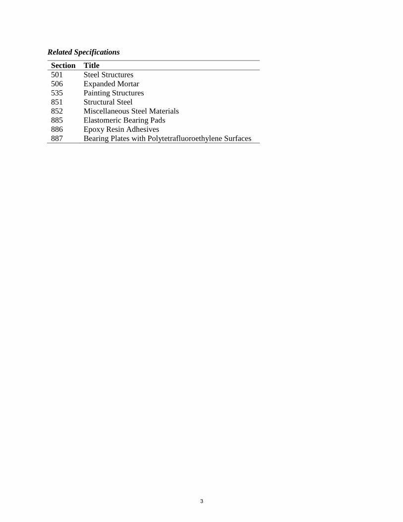
Related Specifications
Section Title 501 506 535 851 852 885 886 887
Steel Structures Expanded Mortar Painting Structures Structural Steel Miscellaneous Steel Materials Elastomeric Bearing Pads Epoxy Resin Adhesives Bearing Plates with Polytetrafluoroethylene Surfaces
3
Georgia Department of Transportation Construction Inspection Training
Incidental Items Inspection
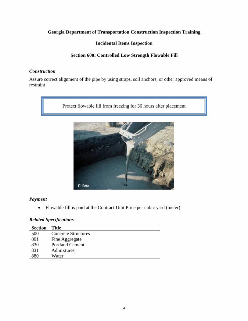
Section 600: Controlled Low Strength Flowable Fill
Construction Assure correct alignment of the pipe by using straps, soil anchors, or other approved means of restraint
Payment
• Flowable fill is paid at the Contract Unit Price per cubic yard (meter) Related Specifications
Section Title 500 801 830 831 880
Concrete Structures Fine Aggregate Portland Cement Admixtures Water
Protect flowable fill from freezing for 36 hours after placement
4
jsungail
Text Box
Georgia Department of Transportation Construction Engineering Inspection Training

Georgia Department of Transportation Construction Inspection Training
Incidental Items Inspection
Section 603: Rip Rap
Foundation Preparation
• Prepare the ground surface where rip rap will be placed to conform with correct lines and grades before beginning the placement
• Compact new material with hand or mechanical tampers when filling depressions
• Begin placing rip rap in a toe ditch constructed in the original ground around the toe of the fill or cut slope
• Compact new material with hand or mechanical tampers when filling depressions • Backfill the toe ditch and spread excess dirt neatly within the right-of-way as an
incidental part of the work after placing rip rap
Ensure toe ditch is 2 ft (600 mm) deep in original ground and the side next to the fill or cut has the same slope
5
jsungail
Text Box
Georgia Department of Transportation Construction Engineering Inspection Training

Stone Rip Rap Placement
Rip Rap Type Placing Description Stone Plain • Dump and handle stone into place to form a compact layer to design
thickness Stone Dumped • Place course at least 2 ft (600 mm) thick
• Use recycled concrete only when materials do not contain steel after processing
Stone Grouted • Prevent earth from filling the spaces between the stones • Fill spaces between 1:3 grout composed of portland cement and sand
mixed thoroughly with enough water to make a thick, creamy consistency
• Place grout beginning at the toe • Finish by sweeping with a stiff-bristle broom
Filter Placement
• Prepare the surface to receive fabric until it is smooth and free from obstructions, depressions, and debris
• Place the fabric with its long dimension running up the slope • Place strips to provide the width at least 1 ft (300 mm) of overlap for each joint
• Anchor filter fabric in place with securing pins of the type recommended by the fabric manufacturer
• Place fabric so that the upstream strip will overlap the downstream strip • Loosely place fabric to prevent stretching and tearing during stone placement • Always protect fabric during construction from clogging due to clay, silts, or chemicals • Remove contaminated fabric or fabric damaged during installation or rip rap placement
Do not drop stones more than 3 ft (1 m) during construction
6

Payment
• Rip rap is paid at the Contract Price per square yard (meter) of material complete in place
Related Specifications
Section Title 800 801 805 815 830 832 880 881
Coarse Aggregate Fine Aggregate Rip Rap and Curbing Stone Graded Aggregate Portland Cement Curing Agents Water Fabrics
7

Georgia Department of Transportation Construction Inspection Training
Incidental Items Inspection
Section 607: Rubble Masonry
Shaping the Stone
• Roughly square the stones on joints, beds, and faces • Use selected stone roughly squared and pitched to line at angles and ends of walls • If specified, finish corners or angles in exterior surfaces with a chisel draft • Shape and dress it before laying stone in the wall
Laying the Stone
• Decrease stone thickness from the bottom to the top of the wall • Ensure headers in the wall are the same size as shown in the face • Ensure that headers in walls 2 ft (600 mm) or less in thickness extend through the wall • Headers shall occupy at least 20% of the wall’s face
• Lay masonry to line and in roughly leveled courses • Lay courses with leaning beds parallel to the natural bed of the material • Regularly diminish the thicknesses of the courses
No dressing or hammering the stone after it is placed
8
jsungail
Text Box
Georgia Department of Transportation Construction Engineering Inspection Training

Weep Holes
• Provide adequate drainage for retaining walls with weep holes as shown on the plans or required by the Engineer
• Build chimneys and French drains extending through parts to be filled and drained when backfilling weep holes
Copings
• Use copings, bridge seats, and back walls made from materials shown on the plans • Use Class A concrete
Payment
• Masonry is paid at the Contract Price per cubic yard (meter) for mortar rubble masonry or dry rubble masonry, complete in place
Do not lay masonry in freezing weather or when the stone contains frost, except with permission
9

Georgia Department of Transportation Construction Inspection Training
Incidental Items Inspection
Section 608: Brick Masonry
Concrete Handling and Placement
• Ensure concrete reaches its final position within 1 hour after adding cement to the aggregates
• Use the following to transport concrete from truck to forms: o Buckets o Buggies o Pumps o Other approved means
• Place concrete without delays
Laying Brick
• Saturate brick with water before laying it • Lay brick using the shove-joint method to bond into the mortar • Arrange headers and stretchers to bond mass thoroughly • Ensure at least 1 course in 7 is a header course • Finish joints properly as the work progresses
Select brick for exposed surfaces, corners, etc. from brick approved as to color and uniformity
10
jsungail
Text Box
Georgia Department of Transportation Construction Engineering Inspection Training

Payment
• Brick masonry is paid at the Contract Price per cubic yard (meter), or per thousand (M) bricks, for brick masonry complete
Do not lay brick in freezing weather or when bricks contain frost
11

Georgia Department of Transportation Construction Inspection Training
Incidental Items Inspection
Section 609: Removal of Portland Cement Concrete Roadway Slabs
Partial Slab Replacements
• Saw the slab full depth longitudinally along the center-line joint and shoulder joint and transversely along the area marked for removal
• Remove saw slurry and other contaminants from the over-cutting beyond the limits of the removal area
• Remove the damaged slabs by lifting
• Drill holes in each slab section to accommodate the expanding type lift anchors • Repair the damaged shoulder area to the Engineer’s satisfaction • Enlarge the removal area to include damaged sections of adjacent concrete • Remove loose underlying base material to produce a sound, well-compacted base • Tamp the material loosened in the removal process to the Engineer’s satisfaction • Dispose of slabs and underlying base material removed during this work • Obtain the disposal site and necessary permits and agreements
Note: Avoid damaging the pavement base, shoulder, or sides that will not be removed
The Engineer will determine which slabs to remove and replace and whether to use full or partial slab replacement
12
jsungail
Text Box
Georgia Department of Transportation Construction Engineering Inspection Training

Payment
• Removal of concrete slabs is paid for at the Contract Unit Price bid Related Specifications
Section Title 886 Epoxy Resin Adhesives
13

Georgia Department of Transportation Construction Inspection Training
Incidental Items Inspection
Section 610: Removal of Miscellaneous Roadway Items
Protection of Remaining Structures
• Do not use explosives, equipment, or devices that may endanger structures, facilities, or other property to remain in place
• If parts of structures are to remain in place, protect those parts from damage during construction
• Protect and preserve the salvage value of materials to be salvaged
Inlets, Catch Basins, Manholes, and Culverts
• Remove gratings, traps, and other metal casting of inlets, catch basins, and manholes without damaging them
• Remove old culverts down to the ground level or to the adjacent water level • Remove the bottom slabs of inlets, catch basins, manholes, and culverts
Removing Pipe
• Uncover the pipe to remove it without damage • Exercise care in removing the pipe • Replace pipe sections damaged by negligence • Clean removed pipe and neatly stack it at points directed by the Engineer along the line
of work
Separate and remove existing structures with their attached parts and connections
14
jsungail
Text Box
Georgia Department of Transportation Construction Engineering Inspection Training

Backfilling
• Use approved materials in the backfill • Compact backfill in layers no more than 6 in. (150 mm) thick with proper moisture
content • Use pneumatic tampers or other approved equipment
Raised Edge Curb
• Remove the raised edge curb to a reasonably true line at elevation of normal finished pavement
• Do not shatter pavement that will be retained Removal of Existing Building Structures
• Demolish, remove, and dispose of all building structures within the right-of-way and easement areas, including concrete slabs, footings, and foundations
• Grade all disturbed ground to a reasonably smooth and pleasing appearance • Provide a copy of all inspection reports of structures to demolish to the Georgia
Environmental Protection Division (EPD)
Payment
• Miscellaneous roadway items are paid at the Contract Unit Price
Inspect all building structures for the presence of asbestos
15

Related Specifications
Section Title 201 202 205 208 540
Clearing and Grubbing Right-of-Way Random Clearing and Grubbing Roadway Excavation Embankments Removal of Existing Bridge
16

Georgia Department of Transportation Construction Inspection Training
Incidental Items Inspection Section 611: Relaying, Reconstructing, or Adjusting to Grade of Misc. Roadway Structures
Miscellaneous Roadway Items Construction
• Remove existing structures to be rebuilt • Clean material salvaged for use in the rebuilt structure and stockpile it in convenient
places • Dispose of portions of structures not suitable for reuse • Relay or rebuild structures • Adjust to the required grade miscellaneous structures specified in the proposal or on the
plans by raising or lowering the upper portion of the fixture • Furnish materials such as mortar, sand–cement grout, sand cushion, bituminous filler,
brick, castings, and other materials to excavate, trench, prepare earth foundation, and backfill
Capping an Existing Structure
• Remove the improvements to expose only the portion of the structure to be modified • Replace the removed improvements to the Engineer’s satisfaction • Remove enough existing masonry to lower the top elevation to a point not less than the
thickness of the cap plus 3 ft • Cap the remaining portion of the structure with a fitted reinforced concrete cover
Resetting Guardrail
• Reset guardrail that was removed • Furnish materials, including additional hardware, offset blocks, and posts • Replace posts that do not conform to the plans
Raising Manholes
• Adjustments may be made by using adjustable extension rings that do not require removal of the existing manhole frame
17
jsungail
Text Box
Georgia Department of Transportation Construction Engineering Inspection Training
• Ensure that the extension device locks to the existing frame and permits height and diameter adjustment
• Choose an extension ring compatible with the existing casting and cover
Payment
• Reconstructing or adjusting miscellaneous roadway structures is paid at the Contract Unit Price
Related Specifications
Section Title 854 Castings and Forgings
Ensure that the extension ring and cover are machine ground to reduce contact irregularity
18

Georgia Department of Transportation Construction Inspection Training
Incidental Items Inspection
Section 612: Construct, Maintain, and Remove Median Crossover
Construction
• Place materials to construct each crossover according to the applicable specifications and as directed by the Engineer
• Place and remove barricades and warning signs as directed by the Engineer • Remove and dispose of materials when the Engineer determines that the crossover has
served its purpose • Reshape the area where the crossover was removed to comply with the appropriate
typical section
Payment
• Crossovers measured as shown above are paid at the Unit Price for each crossover constructed, maintained, and removed
Substitute loose sod if the Engineer approves
19
jsungail
Text Box
Georgia Department of Transportation Construction Engineering Inspection Training

Related Specifications
Section Title 700 Grassing
20

Georgia Department of Transportation Construction Inspection Training
Incidental Items Inspection
Section 613: Docks
Construction
• Ensure the dock is suitable for its intended purpose • Select construction methods as approved by the Engineer • Drive the pile deep enough to provide a safe dock under weather and construction
conditions Related Specifications
Section Title 863 Preservative Treatment of Timber Products
21
jsungail
Text Box
Georgia Department of Transportation Construction Engineering Inspection Training

Georgia Department of Transportation Construction Inspection Training
Incidental Items Inspection
Section 615: Jacking or Boring Pipe
Pipe Jacking
• Excavate suitable pits or trenches for the jacking operation and for placing the end joints of the pipe
• Avoid interfering with facility operation and weakening of roadbed or structure during construction
• Use a jack with a head constructed to apply uniform pressure around the ring of the pipe • Set the pipe to be jacked on guides, braced together properly to support the pipe section
and to direct it to the proper line and grade
• Excavate the roadbed material just ahead of the pipe • Force the pipe through the roadbed into the excavated space • Use an approved mix to pressure grout any voids that develop during installation • Ensure that the excavation does not extend beyond the pipe more than 2 ft (600 mm) • Jack the pipe from the low or downstream end • Use a cutting edge around the head end • Remove and replace pipe damaged in the jacking operations • After completing the jacking, immediately backfill the excavated pits or trenches
22
jsungail
Text Box
Georgia Department of Transportation Construction Engineering Inspection Training

Pipe Boring
• Excavate for pits and shoring installation as outlined above • Locate the pit at the Engineer’s approval • Bore holes mechanically using a pilot hole approximately
2 in. (50 mm) in diameter that is bored the entire length of the installation
• Place excavated material near the top of the working pit and dispose of it as required
• Ensure the diameter of the excavation conforms to the outside diameter of the pipe as closely as possible
Payment
• Jacking and boring pipe is paid at the Contract Price per linear ft (m) of the pipe type, size, and class specified
Related Specifications
Section Title 205 208 550 841 847
Roadway Excavation Embankments Storm Drain Pipe, Pipe-Arch Culverts, and Side Drain Pipe Iron Pipe Miscellaneous Pipe
23
Georgia Department of Transportation Construction Inspection Training
Incidental Items Inspection
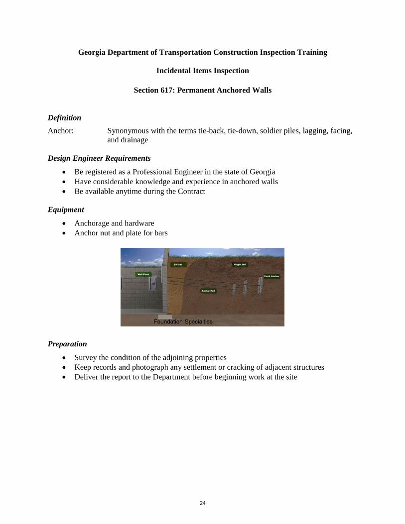
Section 617: Permanent Anchored Walls
Definition Anchor: Synonymous with the terms tie-back, tie-down, soldier piles, lagging, facing,
and drainage Design Engineer Requirements
• Be registered as a Professional Engineer in the state of Georgia • Have considerable knowledge and experience in anchored walls • Be available anytime during the Contract
Equipment
• Anchorage and hardware • Anchor nut and plate for bars
Preparation
• Survey the condition of the adjoining properties • Keep records and photograph any settlement or cracking of adjacent structures • Deliver the report to the Department before beginning work at the site
24
jsungail
Text Box
Georgia Department of Transportation Construction Engineering Inspection Training

Tendons Fabrication
• Keep the tendons free of dirt, rust, or other harmful substances • Use a plastic sheath that is a single piece without splices • Install the sheath at the fabrication drilled location • Handle and store tendons so as to avoid corrosion and physical damage before
installation • Repair damaged coatings in the field at the Engineer’s approval
Payment
• Anchored walls are paid per Lump Sum Related Specifications
Section Title 500 511 853
Concrete Structures Reinforcement Steel Reinforcement and Tensioning Steel
25

Georgia Department of Transportation Construction Inspection Training
Incidental Items Inspection
Section 620: Temporary Barrier
Definitions Method 1:
• Method of furnishing, placing, maintaining, moving, and reusing where required and removing temporary barrier of the proper length and at proper locations
• Not suitable on bridges where the distance from the centerline of the barrier to the free edge of the bridge deck is less than 6 ft (1.8 m)
Method 2:
• Used on bridge and bridge approaches where the distance from the centerline of the barrier to the free edge of the bridge deck is less than 6 ft (1.8 m)
Construction Method 1
• Ensure that units are complete and in acceptable condition • Interconnect all barrier sections within each single run of barrier
Method 2
• Rigidly attach the barrier to the bridge deck and extend it off the bridge a transition distance
• Use nonshrink grout to fill any holes remaining in the permanent bridge decks after the barrier is removed
Handle and transport units to prevent damage
26
jsungail
Text Box
Georgia Department of Transportation Construction Engineering Inspection Training

Payment
• Temporary barrier is paid at the Contract Price per linear ft (m) of barrier Method 1 or barrier Method 2
Related Specifications
Section Title 500 501 511
Concrete Structures Steel Structures Reinforcement Steel
27

Georgia Department of Transportation Construction Inspection Training
Incidental Items Inspection
Section 621: Concrete Barrier
Preparation
• Finish the subgrade to the required lines, grade, and cross section • Compact the subgrade to 100% of the maximum laboratory density • Determine the maximum laboratory dry density from representative samples of the
material compacted
Formed or Slipformed Barriers
• Place the concrete using conventional forms or an approved self-propelled extrusion machine
• Construct joints of the type and at the locations specified on the plans • The Engineer will decide whether to allow a construction joint and will direct where and
how to construct the joint • The outside vertical face of the side barrier or parapet may be battered
28
jsungail
Text Box
Georgia Department of Transportation Construction Engineering Inspection Training

Slipformed Barriers
• Use extrusion machines designed to place concrete barrier or parapet without using forms
• Conform the barrier or parapet to the established shape, line, grade, and dimensions • Obtain the proper density and cross section by forcing an approved concrete mix through
a mold of the proper cross section • Ensure the extrusion machine consolidates the freshly placed concrete in one complete
pass
Payment
• Concrete barrier is paid at the Contract Unit Price per linear ft (m) for each barrier type Related Specifications
Section Title 433 500 833 853
Reinforced Concrete Approach Slabs Concrete Structures Joint Fillers and Sealers Reinforcement and Tensioning Steel
Use a steel trowel to repair and correct the concrete surface
29

Georgia Department of Transportation Construction Inspection Training
Incidental Items Inspection
Section 623: Pneumatically Applied Concrete
Personnel
• Have qualified machine, nozzle, and re-bound operators prepare and apply pneumatically applied concrete under the supervision of qualified superintendents
Equipment
• Use equipment in good operating condition on the Project Earth Foundation Preparation
• Compact and finish the area upon which the pneumatically applied concrete will be placed to the lines and grades shown on the plans
• Ensure the foundation contains enough moisture to provide maximum density and to avoid absorbing water from the concrete
Bonding Foundation Preparation
• Remove unsound or deteriorated concrete, loose particles, dust, and dirt • Clean steel members by sandblasting loose rust, scale, or other deleterious material • Keep the bonding surface wet for at least 1 hour before applying the concrete • Remove any free water immediately before placing
Construction Earth Foundation Construction
• Use gauging wires to establish finish grade lines, surface planes, and plan thickness • Place joints, side forms, shooting strips, weep holes, and reinforcement
30
jsungail
Text Box
Georgia Department of Transportation Construction Engineering Inspection Training

Bonding Foundation Construction
• Reinforce and form concrete according to plan details • When sloping, vertical, or overhanging work surfaces require successive layers or
thickness, allow enough time between application of layers to permit an initial set Placing Reinforcement
• When dowels or anchor bolts are specified, securely fasten the reinforcing steel to them • Lap the welded wire fabric at least 4 in. (100 mm) and firmly tie the full area of mesh or
fabric in position with wire ties • Place welded wire fabric around the top of slab-carrying beams and girders before
pouring the slab • Place the reinforcement at least ½ in. (15 mm) from the surface on which the concrete is
to be placed
Finishing
• Screed the surface and check it with a 10-ft (3 m) straightedge • Remove and replace loose areas of pneumatically applied concrete at the Contractor’s
expense • Protect the adjacent areas that are not to be covered and clean them after application if
necessary
31

Payment
• Pneumatically applied concrete is paid at the Contract Price per square yard (meter) of paving or per ton (megagram) of cement, as specified
Related Specifications
Section Title 441 500 800 801 830 832 833 853 880
Miscellaneous Concrete Concrete Structures Coarse Aggregate Fine Aggregate Portland Cement Curing Agents Joint Fillers and Sealers Reinforcement and Tensioning Steel Water
The Contractor is responsible for all concrete mix designs
32

Georgia Department of Transportation Construction Inspection Training
Incidental Items Inspection
Section 624: Sound Barriers
Wall Types Type B Wall
• Install steel noise barrier walls • Repair cut, scratched, or marred surfaces
Type C Wall
• Concrete precast concrete panels • Cast them in a precasting facility approved by the Engineer • Cast the panels on a steel surface with steel side forms
Type D Wall
• Construct the wall of tongue-and-groove panels placed in a horizontal configuration Type F Wall
• Do not install walls with burns, discolorations, or cracks Type G Wall
• Cast PAAC panels in a precasting facility approved by the Engineer Construction Steps for Type C Wall
• Ensure the curing period is at least 72 hours under normal temperature conditions • Protect panels from freezing from the time the concrete is placed until curing is
complete • Mark each panel with the date cast and the Inspector’s approval stamp
33
jsungail
Text Box
Georgia Department of Transportation Construction Engineering Inspection Training

Wall Construction
• Protect the final ground elevations established in the field for the duration of the Project • Install sound barriers according to the plans and shop drawings approved by the
Engineer • Secure joints and connections to be structurally sound with no visible openings • Repair marred, chipped, scratched, or spalled barrier areas • Place trench backfill for sound barrier construction • Dispose of excess excavation to the Engineer’s satisfaction • Leave the disturbed area in a finished condition at the Engineer’s direction, and plant
grass or sod
Related Specifications
Section Title 106 201 205 206 208 210 500 520 865 885
Control of Materials Clearing and Grubbing Right-of-Way Roadway Excavation Borrow Excavation Embankments Grading Complete Concrete Structures Piling Manufacturing of Prestressed Concrete Bridge Members Elastomeric Bearing Pads
Apply the graffiti-proof coating in weather recommended by the manufacturer
34

Georgia Department of Transportation Construction Inspection Training
Incidental Items Inspection
Section 626: Mechanically Stabilized Embankment Retaining Walls
Wall Crew Supervisor
• Ensure that the wall crew supervisor has previous satisfactory experience in erecting mechanically stabilized walls
Wall Erection
• Adjust the batter to allow for the effect of backfill type, equipment, and construction method on panel movement
• Place panels in successive horizontal lifts as backfill is placed • Maintain a panel in a vertical position when backfilling • Use external bracing for the initial lift • Place cast-in-place concrete on top of the wall panel to bring the precast coping elements
on top of the wall to the proper grade
35
jsungail
Text Box
Georgia Department of Transportation Construction Engineering Inspection Training

Joint Fillers
• Cover joints that are located in a flood plain or other intermittently inundated areas • At other locations, cover joints between panels with a woven or nonwoven plastic filter
fabric sheet • Caulk the openings on either side and between the pads • Ensure that the minimum width based on the manufacturers recommendations of the
plastic filter fabric sheets is used. • Overlap the filter fabric with the joint at least 4 in. (100 mm) • Glue the filter fabric to the panels
MSE Wall Backfill
• Place backfill lift to a uniform thickness and place it from the back face of the wall to 1 ft (300 mm) beyond the end of the soil-reinforcing device level
• Compact the backfill to the full length of the reinforcing devices at each soil-reinforcing device level and slope it to drain away from the wall
• Level the compacted backfill with the connecting device before connecting the reinforcing device
• Repair damaged soil-reinforcing devices or panels before attaching and backfilling the reinforcing devices
• Place soil-reinforcing devices at 90° to the face of the wall • Ensure maximum lift thickness is 8 in. (200 mm) loose and closely follows panel
erection • Compact embankment backfill material to at least 100% of maximum laboratory dry
density • Compact the embankment backfill material without disturbing or displacing the
reinforcing devices and panels
Storm Drains
• Provide precast panels that have the appropriate storm drain openings into panels at elevation and locations indicated on drainage profiles
• Place catch basins so that pipes will enter perpendicular (plan view) to the panels or below the leveling pads as shown on the plans
• Coordinate the catch basin construction and the storm drain placement with the wall construction
36

Related Specifications
Section Title 106 208 500 511 514 535 645 809 812 848 865 867 870
Control of Materials Embankments Concrete Structures Reinforcement Steel Epoxy Coated Steel Reinforcement Painting Structures Repair of Galvanized Coatings Geogrid Materials Backfill Materials Pipe Appurtenances Manufacture of Prestressed Concrete Bridge Members Epoxy Coated Reinforcement Strips Paint
37
Georgia Department of Transportation Construction Inspection Training
Incidental Items Inspection
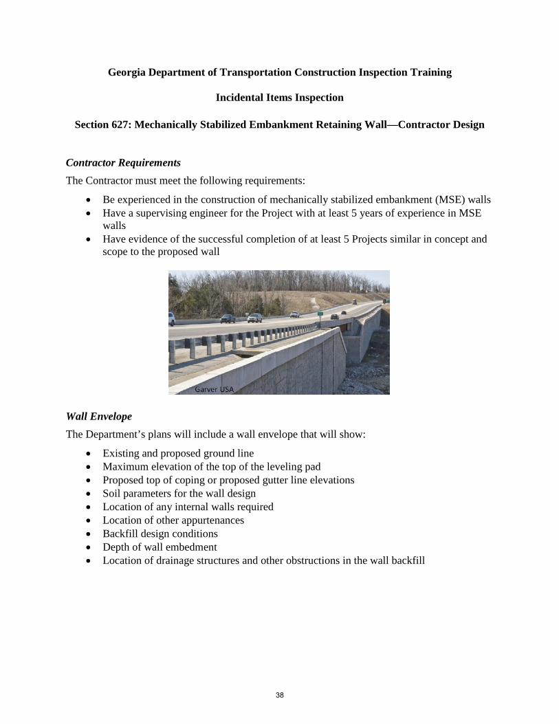
Section 627: Mechanically Stabilized Embankment Retaining Wall—Contractor Design
Contractor Requirements The Contractor must meet the following requirements:
• Be experienced in the construction of mechanically stabilized embankment (MSE) walls • Have a supervising engineer for the Project with at least 5 years of experience in MSE
walls • Have evidence of the successful completion of at least 5 Projects similar in concept and
scope to the proposed wall
Wall Envelope The Department’s plans will include a wall envelope that will show:
• Existing and proposed ground line • Maximum elevation of the top of the leveling pad • Proposed top of coping or proposed gutter line elevations • Soil parameters for the wall design • Location of any internal walls required • Location of other appurtenances • Backfill design conditions • Depth of wall embedment • Location of drainage structures and other obstructions in the wall backfill
38
jsungail
Text Box
Georgia Department of Transportation Construction Engineering Inspection Training

Related Specifications
Section Title 106 208 500 511 514 535 812 848 865 870
Control of Materials Embankments Concrete Structures Reinforcement Steel Epoxy Coated Steel Reinforcement Painting Structures Backfill Materials Pipe Appurtenances Manufacture of Prestressed Concrete Bridge Members Paint
The Engineer must approve any changes to the wall envelope
39

Georgia Department of Transportation Construction Inspection Training
Incidental Items Inspection
Section 632: Portable Changeable Message Signs
Portable Changeable Message Sign (PCMS) Equipment PCMS equipment must:
• Have a control system with a keyboard to allow programming of user-defined messages
• Have primary and backup power sources • Be capable of adjusting its brightness from daylight to nighttime
conditions • Be capable of displaying 3 lines of legend • Have a minimum reliability for its primary power supply for a minimum of 14 days for
solar units
• Have a message displayed on the sign that is visible for 3000 ft (915 m) and legible for not less than 650 ft (198 m) during both daytime and nighttime operation
• Have a self-contained unit that includes a control system with keyboard, primary and backup power source, and mounting and transporting equipment
• Be capable of raising the bottom of the message sign panel a minimum of 7 ft above the roadway
Utilization Requirements
• Utilize PCMS whenever any condition(s) exists that requires extra emphasis in warning motorists of a situation
• The Engineer should determine the location of the PCMS
Gasoline-powered units are not allowed
40
jsungail
Text Box
Georgia Department of Transportation Construction Engineering Inspection Training

• Use PCMS on Interstate, limited-access, and multi-lane divided highways if requirements are met
• Use on all other types of roadways according to the traffic control plan or as directed by the Engineer
Payment
• Changeable message signs, complete with appurtenances, are paid at the Contract Unit Price per each
41

Georgia Department of Transportation Construction Inspection Training
Incidental Items Inspection
Section 634: Monuments and Road Markers
Construction
• Set the monuments and road markers in the ground to the depth shown on the plans
• Use backfilling material of the selected earth or gravel • Carefully tamp it in place so that the monument is stable and
secure • Use a level to set it plumb in all directions
Payment
• Monuments and road markers are paid at the price bid for each, complete in place
Related Specifications
Section Title 500 Concrete Structures
42
jsungail
Text Box
Georgia Department of Transportation Construction Engineering Inspection Training

Georgia Department of Transportation Construction Inspection Training
Incidental Items Inspection
Section 635: Barricades
Construction
• Use timber barricades to warn and alert drivers of the terminus of a road, street, or highway in a nonconstruction or nonmaintenance area
• Install timber barricades where called for on the plans or directed by the Engineer • Ensure barricade rails are marked with alternate red and white stripes • Have stripes slope downward in both directions from the center of the barricade if traffic
may turn right or left
• Make the entire red-and-white striped area of retroreflectorized sheeting materials • Make other barricade components white • Ensure that the barricade has 3 rails as long as specified on the plans • Promptly clean, repair, or replace barricades that are damaged or defaced
43
jsungail
Text Box
Georgia Department of Transportation Construction Engineering Inspection Training

Payment
• Barricades are paid at the Contract Unit Price per linear ft (m) of barricade Related Specifications
Section Title 860 862 863 870 913
Lumber and Timber Wood Posts and Bracing Preservative Treatment of Timber Products Paint Reflectorizing Materials
The Contractor is responsible for all concrete mix designs
44

Georgia Department of Transportation Construction Inspection Training
Incidental Items Inspection
Section 636: Highway Signs
Sign Erection
• Drive posts in place or place in prepared holes • Backfill holes with damp, clean, friable soil and 8% by volume of portland cement • Thoroughly tamp the mixture in place around the posts • Erect steel posts for mast arm assemblies in a concrete foundation • Securely fasten the specified signs into place on the mast arm after curing the concrete
foundation for at least 24 hours
• Erect supporting members of ground-mounted panel-type signs where shown on the plans
• Securely fasten the panels into place • Erect milepost signs including posts • Use delineator posts made of galvanized steel, aluminum, or an alloy • Mount reflectors for galvanized steel or aluminum posts on the flange side of the post
Ensure that the finished signs are clear cut and that the lines of letters and details are true, regular, and free of waviness, unevenness, furry edges or lines, scaling, cracking,
blistering, pitting, dents, or blemishes
45
jsungail
Text Box
Georgia Department of Transportation Construction Engineering Inspection Training

Steps to Erect Signs
• Excavate for the footing to the lines and elevations shown on the plans or established by the Engineer
• Do not disturb or loosen the foundation below these elevations • Use forms of the necessary shape and dimensions to construct the footings to the lines
and elevations shown on the plans • Cure the concrete foundations at least 7 days before erecting the sign • Ensure that the minimum lengths of steel H piling used in the foundations of ground-
mounted signs are accepted • Furnish a list of proposed pile lengths to the Engineer before driving the piles • Place required backfilling in layers no greater than 6 in. (150 mm) thick and thoroughly
compact to the approximate density of the undisturbed soil in the area
Payment
• Highway signs are paid at the Contract Unit Price for the various items
46

Related Specifications
Section Title 500 830 855 870 910 911 912 913 914 915 916 917
Concrete Structures Portland Cement Steel Pile Paint Sign Fabrication Sign Posts Sign Blanks and Panels Reflectorizing Materials Sign Paint Mast Arm Assemblies Delineators Reflectors and Nonreflective Characters
47

Georgia Department of Transportation Construction Inspection Training
Incidental Items Inspection
Section 637: Illuminated Sign System
Power Control
• The photoelectric control operates the lighting conductor that supplies power to the lighting circuit
• Furnish and install a weatherproof transformer to provide a 120 V control voltage • Enclose the wiring to and from the photoelectric control in rigid galvanized conduit
Grounding Rods
• Install grounding rods adjacent to each structural support foundation where the supply voltage enters, and adjacent to the service pole
• Solidly connect the grounding conductor sign framework and metallic, noncurrent-carrying material in the lighting system
• Ensure the neutral/grounding conductor is continuous and connected to the luminaire housing
• Drive the single ground rods vertically until the top of each rod is at least 12 in. (300 mm) below the finished ground
Externally Illuminated Signs
• Ensure the lighting system provides on the face of the signs at least 30 foot-candles
• Mount luminaires so that the top of the luminaire is at least 18 in. (450 mm) below the bottom edge of the sign and at a horizontal distance to provide uniform luminaires
• Support the luminaires and conduit runs with a framework of aluminum or hot-dipped galvanized steel channel solidly fastened to the structural support with galvanized steel or aluminum clamps
48
jsungail
Text Box
Georgia Department of Transportation Construction Engineering Inspection Training
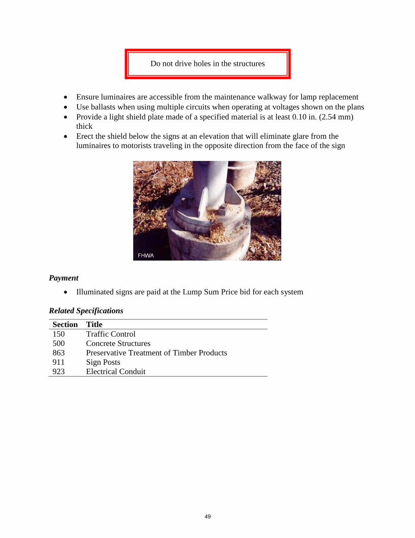
• Ensure luminaires are accessible from the maintenance walkway for lamp replacement • Use ballasts when using multiple circuits when operating at voltages shown on the plans • Provide a light shield plate made of a specified material is at least 0.10 in. (2.54 mm)
thick • Erect the shield below the signs at an elevation that will eliminate glare from the
luminaires to motorists traveling in the opposite direction from the face of the sign
Payment
• Illuminated signs are paid at the Lump Sum Price bid for each system Related Specifications
Section Title 150 500 863 911 923
Traffic Control Concrete Structures Preservative Treatment of Timber Products Sign Posts Electrical Conduit
Do not drive holes in the structures
49

Georgia Department of Transportation Construction Inspection Training
Incidental Items Inspection
Section 638: Structural Supports for Overhead Signs
Protection of Metal
• Protect all metal components to prevent damage of galvanized coatings • Handle galvanized steel components with rope slings • Do not use metal slings, chains, or hooks on galvanized surfaces
Foundations
• Chamfer the edges of the stems ¾ in. (19 mm) • Ensure stems have a Type III finish to at least 6 in. (150 mm) below the finished ground
surface • The Engineer must inspect the anchor bolt assembly installation before placing concrete • Do not remove the temporary template until the footing and stem concrete have been in
place at least 24 hours
Erection
• Place and level a leveling nut on each anchor bolt • Use a washer with each leveling nut • Set the column on the washers without the horizontal structure and tighten a washer and
secure a nut on each anchor bolt • Inspect the connections to ensure full bearing of the top and bottom of the washers on
the base plate • No structure will be accepted if this dimension is greater than 4 in. (100 mm)
Metal components will be rejected if they have extensive damage to the galvanizing
50
jsungail
Text Box
Georgia Department of Transportation Construction Engineering Inspection Training

Grounding
• Vertically drive a single, 8-ft (2.4 m) long ground rod until the top of the rod is at least 12 in. (300 mm) below the finished ground
• Attach a length of #6 bare copper, 7-strand wire to the ground with suitable ground rod clamps
• Connect the wires to the grounding nut of the column Payment
• Structural supports for overhead signs are paid at the Lump Sum Contract Unit Price bid Related Specifications
Section Title 207 500 501 511 833 852
Excavation and Backfill for Minor Structures Concrete Structures Steel Structures Reinforcement Steel Joint Fillers and Sealers Miscellaneous Steel Materials
51

Georgia Department of Transportation Construction Inspection Training
Incidental Items Inspection
Section 639: Strain Poles for Overhead Sign and Signal Assemblies
Timber Poles Construction
• Excavate the hole to the proper diameter and depth • Erect the pole to an out-of-plumb position with its base resting
on the bottom of the hole • Hold the pole in its out-of-plumb position until the cavity
around the pole is filled and compacted Prestressed Concrete Poles Construction
• Do not disturb the natural ground adjacent to the foundation more than necessary to construct the foundation
• Excavate to the lines and elevations shown on the plans • Dispose of the excavated materials as directed • Regrade and grass the disturbed areas to match the contiguous area • Backfill according to the plans • Furnish and place Class A concrete • Burn off and patch lifting eyes or loops on the pole that facilitate handling
Ground Rod
• Use exothermic weld or ground rod clamps to attach the length of copper wire to the ground rod
• Place 3 parallel ground rods at least 6 ft (1.8 m) center-to-center in a horizontal pattern and at least 12 in. (300 mm) below the finished ground
Cable Erection
• Install the top cable 6 in. (150 mm) from the top of the pole • Install the bottom cable no more than 5 ft (1.5 m) from the pole’s
top • Secure the cable to each pole • Use preformed cable grips instead of cable clamps • Apply enough tension to pull the timber poles toward each other past the plumb position
by one degree
Minimum sag of a cable attached to a timber pole is 2.5%
52
jsungail
Text Box
Georgia Department of Transportation Construction Engineering Inspection Training
Related Specifications
Section Title 500 852 861 863 865 915
Concrete Structures Miscellaneous Steel Materials Piling and Round Timber Preservative Treatment of Timber Products Manufacture of Prestressed Concrete Bridge Members Mast Arm Assemblies
53

Georgia Department of Transportation Construction Inspection Training
Incidental Items Inspection
Section 640: Retroreflectorized Railroad Cross Buck Sign
Setting a Steel Post
• Set each steel post for a sign assembly in a concrete foundation • Securely hold each post vertically until the concrete is strong enough to hold the post
and sign without support • Replace cracked bases • Carefully tamp the backfill in place
Setting a Wood Post
• Place each post in the prepared dry hole of at least 6-in. (150 mm) diameter
• Backfill the hole with a mixture of Portland cement and damp and clean soil using 8% cement by volume
• Thoroughly tamp the resultant mixture into place around the post
• Erect the post vertically to a depth and angle provided in the project specifications to the roadway
• Ensure the post penetrates the ground at least 4 ft (1.2 m)
Payment
• Retroreflectorized railroad cross buck signs are paid per each
Backfill around the bases with satisfactory material
54
jsungail
Text Box
Georgia Department of Transportation Construction Engineering Inspection Training

Related Specifications
Section Title 500 Concrete Structures
55

Georgia Department of Transportation Construction Inspection Training
Incidental Items Inspection
Section 641: Guardrail
Guardrail Post Erection
• Do not allow use of wood posts at any location except as required for guardrail anchorage
• Set posts in post holes or drive them vertically at the positions, depth, spacing, and alignment shown on the plans
• Install posts for guardrail on bridges or other structures as detailed on the plans • Backfill post holes to the ground line with approved material tamped in place • Protect the tops of posts with a suitable driving mat or cap
• Backfill post holes that are drilled in rock • Remove and reset posts that are out of alignment or too low in grade • Fit posts with an offset block • Set additional posts and appurtenances according to requirements of the GDOT Standard
Specifications and project plan details
Guardrail Construction
• Erect rails to attain a smooth, continuous rail line that conforms to the line and grade of the highway
• Use bolts long enough to extend at least ¼ in. (6 mm) beyond the nuts after they are firmly tightened
Do not cut posts that are too high—drive them to the proper elevation.
56
jsungail
Text Box
Georgia Department of Transportation Construction Engineering Inspection Training

• Install reflectorized washers on guardrail and anchorages • Install reflectorized washers only on the side that is nearest traffic
Payment
• Guardrail, of the type specified, complete in place including posts, offset blocks, and hardware, are paid at the Contract Price per linear ft (m)
• Guardrail anchorage assembly is paid at the Contract Price per each Related Specifications
Section Title 205 208 859 870
Roadway Excavation Embankments Guardrail Paint
57

Georgia Department of Transportation Construction Inspection Training
Incidental Items Inspection
Section 643: Fence
General Fencing Requirements
• Construct fence (except field fence) within the right-of-way line • Do not allow permanent installation to encroach on adjacent property • Construct fence to follow the contour of the ground • Place the bottom of the fence fabric at least 1 in. (25 mm) from the ground surface
• Clean the fence line a maximum of 8 ft (2.4 m) wide and grade where necessary • Use longer posts to maintain ground clearance when the ground profile changes • Place corner or end posts at the junction with existing fences and fasten wires in the new
and existing fences to the posts • Install corner or pull posts for new fencing without placing tension on existing posts
Connect existing cross fences to new fencing
58
jsungail
Text Box
Georgia Department of Transportation Construction Engineering Inspection Training

Post and Appurtenance Construction
• Place and install posts as shown on the plans • Encase concrete line posts installed in marshy or swampy areas • Encase the corner, end, and pull posts in concrete • Replace posts damaged by driving • Fill the entire hole around a post with Class A or B concrete • Add additional approach posts for greater stability • Fill space around the post with molten lead or a cement filler • Repair posts after cutting or drilling • Treat timber posts and braces with a preservative coating
Gates
• Ensure gate assemblies are the length, height, and type designated on the plans (must provide a 180-degree swing)
Temporary Barrier Fence
• Use suitable metal, wood, or composite posts • Ensure the posts are long enough to be embedded to a depth that will provide stability to
a fence • Allow a maximum post spacing of 10 ft (3 m) • Attach the fence to the posts with nails, staples, or wire ties spaced every 6 in. (150 mm)
along the posts • Do not allow the method of attachment to create a safety hazard
Payment
• Fence is paid at the Contract Unit Price per linear ft (m) of the specified type and height of fence
59

Related Specifications
Section Title 500 862 863 894
Concrete Structures Wood Posts and Bracing Preservative Treatment of Timber Products Fencing
60

Georgia Department of Transportation Construction Inspection Training
Incidental Items Inspection
Section 645: Repair of Galvanized Coatings
Construction
• Apply repair compound smoothly and evenly with a moderately filled paint brush • Apply when the temperature of the steel compound and surrounding air is above 45°F • Ensure a minimum dry film thickness is 2 mils (0.05 mm) on smooth surfaces • The Engineer may require one coat on rough and pitted surfaces
Payment
• Repair of galvanized coatings is performed at the Contractor’s expense Related Specifications
Section Title 870 Paint
Do not brush over partly dried applications
61
jsungail
Text Box
Georgia Department of Transportation Construction Engineering Inspection Training

Georgia Department of Transportation Construction Inspection Training
Incidental Items Inspection
Section 647: Traffic Signal Installation
General
• Return to the District Traffic Signal Shops all traffic signal equipment removed or replaced
• Provide an inventory list and arrange a mutually agreeable delivery time with the District Signal Engineer a minimum of 24 hours in advance
Traffic Signal Equipment Modification and Removal
• Remove existing signal equipment that is not used in the final installation when the new signal equipment is operational
• Carefully remove equipment to minimize damage and retain it in its original form • Replace traffic signal equipment that the District Signal Engineer determines has been
damaged or destroyed during installation, modification, or removal of the traffic signal • If the Engineer finds that the existing material shown in the plans to be relocated is
unsatisfactory, replace it with new material • Remove old signal heads by the end of the day • Remove other signal equipment within 7 days after operation of the installed equipment
Do not modify the signal equipment, design, and operation without the District Traffic Operations Engineer’s written approval
62
jsungail
Text Box
Georgia Department of Transportation Construction Engineering Inspection Training

Signal Controller Installation
• Identify the controller and other auxiliary equipment by model and revision numbers • Assemble the controller, cabinet, and auxiliary equipment to provide the operational
sequence shown in the plans and future operations specified • Ensure controller and auxiliary equipment are provided AC
power from receptacles marked for controller power • The Department will provide controller firmware • The Contractor shall deliver signal controllers 30 days prior to
installation Cabinet Assembly
• Locate the cabinet in accordance with the plan location • Install and level traffic signal controller cabinets at locations
shown in the plans • Do not allow the cabinet base to extend more than 9 in. above
final grade Signal Monitors
• Mount signal monitors in a rack with appropriate connectors to attach to the wiring harness
• Program the monitor according to the signal operation indicated in the signal plans • Configure and equip the signal monitor to monitor all red signal indications
Power Disconnect
• Install a box at each intersection • Ensure the power disconnect is installed at the top of the cabinet or as indicated on the
plans • Program the monitor according to the signal operation indicated in the signal plans • Install service cables from the disconnect box and terminate
63

Related Specifications
Section Title 106 107 108 150 500 501 535 755 800 801 832 833 850 852 853 854 861 870 886 910 911 912 913 915 922 923 924 925 926 927 935 936 937 939 940
Control of Materials Legal Regulation and Responsibility to the Public Prosecution and Progress Traffic Control Concrete Structures Steel Structures Painting Structures Electrical Work Coarse Aggregate Fine Aggregate Curing Agents Joint Fillers and Sealers Aluminum Alloy Metals Miscellaneous Steel Materials Reinforcement and Tensioning Steel Castings and Forgings Piling and Round Timber Paint Epoxy Resin Adhesives Sign Fabrication Sign Posts Sign Blanks and Panels Reflectorizing Materials Mast Arm Assemblies Electrical Wire and Cable Electrical Conduit Miscellaneous Electrical Materials Traffic Signal Equipment Wireless Communication Equipment Wireless Communication Installation Fiber Optic System Closed Circuit Television (CCTV) Detection Systems Communication and Electronic Equipment NaviGator Advanced Transportation Management System Integration
64

Georgia Department of Transportation Construction Inspection Training
Incidental Items Inspection
Section 648: Traffic Impact Attenuator
Definitions Gating: A gating end treatment allows a vehicle impacting the nose or the side of the unit
at an angle near the nose to pass through the device Non-Gating: A non-gating end treatment is capable of redirecting a vehicle impacting the nose
or the side of the unit along the unit’s entire length
Construction
• Field locate the position of the attenuator nose as shown on the plans • Increase the length of the concrete transition section or length of the longitudinal barrier
as needed to provide a proper beginning point for the attenuator nose • Consider the length of the system to be the combined length of the attenuator unit/array,
the back-up system, and any required transition • Ensure the length of the system is not excessive to the extent that it intrudes appreciably
within the clear offset distance as shown on the plans • Ensure temporary portable units/arrays are installed, moved, reinstalled, and maintained
as required
Payment: Impact attenuator units/arrays will be paid per each type specified
65
jsungail
Text Box
Georgia Department of Transportation Construction Engineering Inspection Training

Georgia Department of Transportation Construction Inspection Training
Incidental Items Inspection
Section 649: Concrete Glare Screen
Glare Screen Alternatives Construct the glare screen using one of the following:
• Alternative One: o Cast the median barrier and insert “D” bars into the fresh, plastic concrete o Wait until the median barrier concrete has reached a compressive strength of
2000 psi on an age of 7 days
• Alternative Two: o Wait until the median barrier concrete has reached a compressive strength of
2000 psi, then drill and place “D” bars o Construct the second course of barrier on top of the first course
Payment
• Concrete glare screen is paid at the Contract Unit Price per linear ft (m) for each specified height
66
jsungail
Text Box
Georgia Department of Transportation Construction Engineering Inspection Training
Georgia Department of Transportation Construction Inspection Training
Incidental Items Inspection
Section 651: Raised Traffic Bars
Construction
• Use concrete materials, and mix and place Class A, air-entrained concrete • Make forms accessible for tamping and vibrating concrete • Do not use curing compound on the bottom surfaces
Cement Bar Installation to the Pavement
• Sandblast the highway surface of dirt, curing compound, grease, oil, moisture, loose or unsound layers, and other material that would prevent the bar adhesive from bonding
• Use epoxy resin type IR or IS • Place enough adhesive on the cleaned pavement, or on the bottom of the bar, to
completely cover the area of contact with no voids • Position the bar and press firmly into the pavement
Payment
• Raised traffic bars are paid at the Contract Unit Price per linear ft (m) Related Specifications
Section Title 500 886
Concrete Structures Epoxy Resin Adhesives
Do not use thinners or solvents to remove the adhesive
67
jsungail
Text Box
Georgia Department of Transportation Construction Engineering Inspection Training

Georgia Department of Transportation Construction Inspection Training
Incidental Items Inspection
Section 652: Painting Traffic Stripe
Definitions Painted Stripes: Solid or broken (skip) lines Skip Traffic Stripes: Painted segments with unpainted gaps
Construction
• Ensure accurate stripe location by establishing control points at spaced intervals • Apply the traffic stripe paint by machine • Change the minimum rate proportionately for varying stripe widths • Do not paint areas of pavement when the air temperature in the shade is below 50°F • Apply a layer of glass spheres and reflective composite optics immediately after laying
the paint
Protective Measures
• Control and protect traffic with warning and directional signs during painting • Set up warning signs before beginning each operation, and place signs well ahead of the
painting equipment
68
jsungail
Text Box
Georgia Department of Transportation Construction Engineering Inspection Training

Payment
• Painting stripes is paid at the Lump Sum Contract Unit Price bid Related Specifications
Section Title 870 Paint
Protect freshly painted stripe using cones or drums
69

Georgia Department of Transportation Construction Inspection Training
Incidental Items Inspection
Section 653: Thermoplastic Traffic Stripe
Definitions Thermoplastic Marking Compound: A heated compound extruded or mechanically sprayed on
the pavement that cools to pavement temperature Short Lines: Crosswalks, stop bars, arrows, symbols, and crosshatching
General Application
• Clean the pavement areas to be striped • Use hand brooms, rotary brooms, air blasts, or scrapers to clean • Remove all vegetation and road film from the striping area • Apply the material only when the pavement temperature in the shade is above 40°F
• Ensure the new striping paint material bonds on top of the old line (if applicable) without splitting or cracking
• Remove 100% of the existing traffic stripe • Do not allow traffic onto or permit vehicles to cross newly applied pavement markings
until they are sufficiently dry determined by visual inspection.
Lay the stripe with continuous uniform dimensions
70
jsungail
Text Box
Georgia Department of Transportation Construction Engineering Inspection Training

Georgia Department of Transportation Construction Inspection Training
Incidental Items Inspection
Section 654: Raised Pavement Markers
Adhesive Types Type I-R Epoxy: Use when the pavement temperature is above 50°F or when traffic
conditions require a rapid-setting system Type I-S Epoxy: Use when the pavement temperature is above 60°F and traffic conditions
permit a slower setting system Bituminous Adhesive: Use when the pavement temperature is above 40°F or when traffic
conditions require a rapid-setting material
Placement of Markers
• Clean the pavement of dirt, curing compound, grease, oil, paint, moisture, or unsound layers
• Use either sandblasting or grinding equipment to clean
71
jsungail
Text Box
Georgia Department of Transportation Construction Engineering Inspection Training

• Do not place markers when the pavement temperature is below 40°F • When possible, wait 60 to 90 days before placing markers using epoxy adhesive on
newly constructed asphaltic concrete pavements
Placing Marker Using Epoxy Adhesives
• Place enough adhesive on the cleaned pavement or the bottom of the marker to completely cover the contact area of the marker
• Press the marker firmly to the pavement • Allow a slight bead of epoxy adhesive to extrude from under the marker edges • Remove adhesive on the face of the marker
Payment
• Raised pavement markers are paid at the Unit Price for each Unit of each type Related Specifications
Section Title 868 886 919
Bituminous Adhesive for Raised Pavement Markers Epoxy Resin Adhesives Raised Pavement Markers
Do not use thinners to clean epoxy from the marker
72

Georgia Department of Transportation Construction Inspection Training
Incidental Items Inspection
Section 655: Pavement Arrow with Raised Reflectors
Thermoplastic Arrow Application
• Apply thermoplastic 125 mils (3.18 mm) thick • Screed or level the thermoplastic • Immediately embed the raised reflector in the molten thermoplastic
Payment
• Each arrow is paid per Unit placed Related Specifications
Section Title 868 870 886 913 919
Bituminous Adhesive for Raised Pavement Markers Paint Epoxy Resin Adhesives Reflectorizing Materials Raised Pavement Markers
73
jsungail
Text Box
Georgia Department of Transportation Construction Engineering Inspection Training

Georgia Department of Transportation Construction Inspection Training
Incidental Items Inspection
Section 656: Removal of Pavement Markings
Construction
• Utilize blasting, such as sandblasting or water blasting, or grinding to remove pavement markings without damaging the pavement surface
• Do not allow sand and other debris to accumulate and interfere with drainage • Immediately remove residue and dust from the blast cleaning • Use a vacuum attachment operating simultaneously with the blast cleaning
Payment
• Markings removal is paid at the Contract Unit Price per Unit Related Specifications
Section Title 107 150 804
Legal Regulations and Responsibility to the Public Traffic Control Abrasives for Blast Cleaning
Remove pavement markings before changing the traffic pattern
74
jsungail
Text Box
Georgia Department of Transportation Construction Engineering Inspection Training

Georgia Department of Transportation Construction Inspection Training
Incidental Items Inspection
Section 657: Preformed Plastic Pavement Markings
Pre-Conditions for Marking Application
• Ambient temperature is 40°F and rising • New asphaltic pavement temperature is at least 120°F • The plastic can be applied to new asphaltic pavement immediately before the new
surface is rolled for the final time • No significant rainfall occurred 24 hours prior to the plastic’s application
Marking Application
• Thoroughly clean the pavement with compressed air, hand brooms, or rotary brooms • Remove all vegetation and road film • Mechanically wire brush or abrasive blast clean all new portland cement concrete • Apply an adhesive activator according to the manufacturer’s recommendations • Position markings according to the plans • Press positioned markings firmly onto the pavement • Offset longitudinal lines at least 2 in. (50 mm) from construction joints of portland
cement concrete pavements Related Specifications
Section Title 107 150 804
Legal Regulations and Responsibility to the Public Traffic Control Abrasives for Blast Cleaning
75
jsungail
Text Box
Georgia Department of Transportation Construction Engineering Inspection Training

Georgia Department of Transportation Construction Inspection Training
Incidental Items Inspection
Section 658: Polyurea Traffic Stripe
Definitions Painted Stripes: Solid or broken (skip) lines Skip Traffic Stripes: Painted segments between unpainted gaps on a designated sequence with
a ratio of 1:3 General Construction
• Apply pavement markings only during conditions of dry weather and subsequently dry pavement surfaces
• Ensure that the pavement surface temperature and the ambient temperature at the time of installation are both greater than 40°F and that the relative humidity is less than 85%
• Ensure that the traffic stripe is the specified length, width, and placement
Pavement Marking Application
• Apply the liquid marking material by spray method and according to the manufacturer’s installation instructions
• Ensure marking configurations are in accordance with the Manual on Uniform Traffic Control Devices
• Place the reflectorized pavement markings only on properly prepared surfaces and at the widths and patterns designated on the plans
Air-blast the surface first, to remove any dirt and residues from the pavement
76
jsungail
Text Box
Georgia Department of Transportation Construction Engineering Inspection Training

• Apply the pavement markings as a continuous operation • Heat Component A and Component B to the manufacturer’s recommended temperatures • Ensure that mixing of the two components occurs in a static tube or impingement
chamber prior to reaching the application spray nozzle • Immediately following application, drop the glass spheres and/or reflective composite
optics onto the liquid marking
77

Georgia Department of Transportation Construction Inspection Training
Incidental Items Inspection
Section 659: Hot Applied Preformed Plastic Pavement Markings
Pre-Conditions for Applying Markings with Heat
• Apply markings when the ambient temperature is 35°F or above • Apply markings when the pavement is clean, dry, and free of debris • Apply drop-on glass beads to the entire surface of preformed markings that do not have
factory pre-applied surface beads • Apply the drop-on glass beads to the preformed marking material while it is in a liquid
state
78
jsungail
Text Box
Georgia Department of Transportation Construction Engineering Inspection Training

Georgia Department of Transportation Construction Inspection Training
Incidental Items Inspection
Section 666: Vertical Drainage Wicks
Drain Installation
• Ensure the mandrel of the sleeve completely encloses and protects the drainage wick • Force the mandrel containing the wick vertically into the ground at the required depth • Cut the mandrel neatly at its upper end after installation • Ensure that a 4–8 in. (100–200 mm) length of wick protrudes from the ground • If necessary, drill through the dense upper soils before installing the prefabricated drains • Do not drill more than 2 ft (600 mm) into the underlying compressible soils, as
determined by the Engineer
Payment
• Vertical drainage wicks are paid at the Contract Price for the accepted quantity of drilled holes and vertical drainage wicks
Related Specifications
Section Title 106 Control of Materials
Install to the depth shown on the Plans, or where reasonable efforts to further penetrate fail
79
jsungail
Text Box
Georgia Department of Transportation Construction Engineering Inspection Training

Georgia Department of Transportation Construction Inspection Training
Incidental Items Inspection
Section 668: Miscellaneous Drainage Structures
Poured-in-Place Concrete Units
• Allow use of Class B concrete for the throat or other nonreinforced portions of catch basins
• Use Class A concrete for the top slab Pre-Cast Reinforced Concrete Units
• Cast each unit with the number and dimensions of pipe holes necessary to incorporate the unit into the drainage system
• Use mortar or Class A concrete to connect pipe to units • Set units to within ½ in. (15 mm) of grade on a bed of compacted sand between 2 in. to 3
in. thick Castings: Hold the frame securely in place to the proper line and grade, which makes it an
integral part of the complete structure Sanitary Sewer Manholes
• Shape invert channels to lines and grades as shown on plans • Ensure the channel surfaces are smooth • Directly place the invert channel in the concrete base of the manhole • Construct the invert channel of brick and mortar • Lay half-round tile in the concrete base of the manhole • Lay round sewer pipe through the manhole and cut out the top half of the pipe after the
concrete base has set Related Specifications
Section Title 207 500 607 608 801 830 834 843 853 854
Excavation and Backfill for Minor Structures Concrete Structures Rubble Masonry Brick Masonry Fine Aggregate Portland Cement Masonry Materials Concrete Pipe Reinforcement and Tensioning Steel Castings and Forgings
80
jsungail
Text Box
Georgia Department of Transportation Construction Engineering Inspection Training

866 Precast Concrete Catch Basin, Drop Inlet, and Manhole Units
81

Georgia Department of Transportation Construction Inspection Training
Incidental Items Inspection
Section 680: Highway Lighting
Conduit Installation
• Cut metallic conduit threads and then ream the ends • Ream other conduit as necessary • Cut conduit ends square • Ensure that conduit ends butt solidly in the joints to form a smooth raceway for cables
Conduit on Structures
• Run conduit parallel to beams, trusses, supports, pier caps, etc., as directly as possible • Install horizontal runs in a slight grade without forming low spots that may prevent
proper drainage • Run conduits with smooth, easy bends • Hold conduit in boxes with locknuts • Do not clamp or attach conduit to the beam flanges • Use bushings to protect the conductors
Pull and Junction Box Construction
• Construct concrete boxes from Class A concrete • Ensure that precast concrete boxes follow the same requirements • Provide cast iron, steel, or reinforced concrete covers with each pull or junction box
according to the plans • Ground the cast iron or steel covers to the electrical junction or pull boxes
Light Standard and Tower Installation
• Install the specified design, kind, and size of light standards or towers at plan-specified locations
82
jsungail
Text Box
Georgia Department of Transportation Construction Engineering Inspection Training

• Install these structures, complete with specified supporting assembly and luminaires, to the mounting heights shown on the plans
• Consider transformer bases to be an integral part of the lighting standard
Luminaires
• Mount or install the specified design and size of luminaire shown on the plans
• Level according to the manufacturer’s recommendations and plan details, and as approved by the Engineer
• Provide glare shields on luminaires if required by the plans • Where a lighting unit illuminates a roadway portion on a grade,
rotate the luminaire on its major axis to bring the minor axis parallel to the roadway
• Clamp cables into the proper terminals on the luminaire’s terminal board • Leave enough slack in the cables to check or replace the fuse outside of the handhole • Leave slack in the cables for future maintenance • Attach a suitable identification tag to each phase cable, using white for the neutral
grounding wire Power Source
• Make prior arrangements for furnishing power to operate the lighting system • Notify the power company at least 30 days before needing to connect to the power
source • Connect the lighting system to the secondaries of the local power supplier’s overhead or
underground distribution system • Install the service pole, metallic conduit riser, weatherproof circuit breaker, and
weatherhead with enough wire to connect to the power source
Never attempt to realign the anchor bolts after placing the foundation
83

Related Specifications
Section Title 205 500 800 801 832 853 854 870 920 921 922 923 924
Roadway Excavation Concrete Structures Coarse Aggregate Fine Aggregate Curing Agents Reinforcement and Tensioning Steel Castings and Forgings Paint Lighting Standards and Towers Luminaires Electrical Wire and Cable Electrical Conduit Miscellaneous Electrical Materials
84

Georgia Department of Transportation Construction Inspection Training
Incidental Items Inspection
Section 682: Electrical Wire, Cable, and Conduit
Construction
• Furnish and install electrical cables, conduit, and power service necessary to make the system fully operational
• Identify all conductors of all cables by color and number
• Identify the conductor function in the as-built documentation • Install telephone service cable directly to or into the equipment cabinet in accordance
with telephone company procedures • Install electrical conduit to provide enclosures for electrical cables at the terminating
junction • Make all aboveground electrical conduit and conduit bodies of rigid metal • Terminate all aboveground conduit in either a weather head or in a cabinet
• Require that all conduits entering a pole-mounted equipment cabinet enter through the bottom with at least one conduit body with a sealable, removable cover for pulling access
• Require that all conduits entering in a base-mounted cabinet enter through the foundation and the base-mount adapter
Do not splice any cable, shield, or conductor used for power
85
jsungail
Text Box
Georgia Department of Transportation Construction Engineering Inspection Training

Related Specifications
Section Title 205 208 922 923
Roadway Excavation Embankments Electrical Wire and Cable Electrical Conduit
86

Georgia Department of Transportation Construction Inspection Training
Incidental Items Inspection
Section 685: Blast Cleaning Portland Cement Concrete Structures
Blast Cleaning Methods Use any of the following methods:
• Dry abrasive blasting with compressed air, blast nozzles, and abrasive • Recirculating dry abrasive blasting with compressed air, blast nozzles, abrasive, and a
recovery system • Wet abrasive blasting with compressed air, blast nozzles, abrasive, and a water injection
system
Blast Cleaning Operation
• Provide and maintain traps to prevent contaminating the blasted substrate with oil or grease
• Immediately remove residue to prevent a traffic hazard when blasting within 10 ft (3 m) of a lane occupied by traffic
• Control dust to protect motorists from reduced visibility or damage to passing vehicles Payment
• Blast cleaning is paid at the Contract Unit Price bid
87
jsungail
Text Box
Georgia Department of Transportation Construction Engineering Inspection Training

Georgia Department of Transportation Construction Inspection Training
Incidental Items Inspection
Section 690: Static Scale System
Reinforced Concrete Scale Pit Construction
• Install the scale pit concrete including sleeves, piping, conduits, anchors, and frames • Use deformed billet steel bars for bar reinforcement steel • Make the top of the pit and aprons flush and level with the adjoining pavement • Furnish and install a pit drain connected to a 4-in. (100 mm) drain line
• Provide a float-controlled high-water alarm system in the scale pits that automatically activates a red warning light to the operator
• Install an alarm buzzer with the high-water alarm system in the operator’s tower • Provide scale pits with an access cover and manhole
Payment
• Scale pits are paid at the Lump Sum Contract Unit Price bid
Enclose each scale platform and pit with steel coping
88
jsungail
Text Box
Georgia Department of Transportation Construction Engineering Inspection Training

Related Specifications
Section Title 105 108 109 500 511 853
Control of Work Prosecution and Progress Measurement and Payment Concrete Structures Reinforcement Steel Reinforcement and Tensioning Steel
89

Georgia Department of Transportation Construction Inspection Training
Incidental Items Inspection
Section 691: Weigh-in-Motion Scale System
Scalepit and Weighing Platform
• Install a drain line to an outlet beyond the shoulder pavement • Make the entire weigh-in-motion scales flush with the pavement • Ensure that the completed scales do not rock or hammer • Hermetically seal and treat the load cells to prevent moisture penetration and corrosion
under normal pit conditions
Inductive Loops
• Saw cut the pavement, install the loop wires, and seal the saw cuts • Provide a loop detector in the bypass lane that detects a vehicle that was directed by the
automatic sorting system to proceed to the static axle scales but has incorrectly proceeded to the bypass lane
Control Signs and Indicators
• Provide a high-intensity light on the back of each overhead signal head that will illuminate at the same time the green arrow is illuminated
• Install two repeater pin lights at the weigh-in-motion console that indicate the vehicle has been directed to the static scales or the bypass lane
• Provide a manual switch in the operations office to override the automatic mode of the overhead signs
Payment
• Weigh-in-motion scale systems are paid at the Contract Lump Sum Price
Equip the loop detector to activate a buzzer at the operator’s console
90
jsungail
Text Box
Georgia Department of Transportation Construction Engineering Inspection Training

Related Specifications
Section Title 105 108 109 500 511 680 923
Control of Work Prosecution and Progress Measurement and Payment Concrete Structures Reinforcement Steel Highway Lighting Electrical Conduit
91

Georgia Department of Transportation Construction Inspection Training
Incidental Items Inspection
Section 700: Grassing
General Inspection Notes
• Obtain the Engineer’s approval before changing the ground cover type • Do not use annual rye grass seeds with permanent grassing • Follow the planting zones indicated on the Georgia State Planting Zone Map • Sod may be installed throughout the year (weather permitting)
Ground Preparation
• On slopes 3:1 or flatter, plow shoulders and slopes to between 4 in. and 6 in. deep • Plow front and back slopes in cuts to no less than 6 in. deep • Serrate slopes steeper than 3:1 according to plan details when required • Remove boulders, stumps, large roots, large clods, and other objects • Spread topsoil stockpiled during grading evenly over cut and fill slopes • Push topsoil from the top over the serrated slopes • Do not operate equipment on the face of the completed serrated cuts
Seed Preparation and Sowing
• Inoculate each kind of leguminous seed separately with the appropriate commercial culture according to the manufacturer’s instructions for the culture
• Sow seed within 24 hours after preparing the seed bed and applying fertilizer and lime • Sow seed uniformly at the rates specified in the seeding tables
The Engineer has the authority to alter the planting dates as set forth by a period of 2 weeks
92
jsungail
Text Box
Georgia Department of Transportation Construction Engineering Inspection Training

• Allow temporary grass areas that were prepared to be overseeded using the no-till method
• Use Riparian seed mix when specified in the plans
Sod Requirements and Preparation
• Use only common bermudagrass or a specified bermudagrass variety • Ensure that sod is nursery-grown and accompanied with a Georgia Department of
Agriculture Live Plant License Certificate or Stamp • Furnish either a big roll or block sod • Apply lime and fertilizer within 24 hours prior to installing sod
Related Specifications
Section Title 160 163 718 822 882 890 891 893 895
Reclamation of Material Pits and Waste Areas Miscellaneous Erosion Control Items Wood Fiber Emulsified Asphalt Lime Seed and Sod Fertilizers Miscellaneous Planting Materials Polyacrylamide (PAM)
References www.thedailygreen.com
www.fiskars.com
No dwarf Bermuda types shall be used
93

Georgia Department of Transportation Construction Inspection Training
Incidental Items Inspection
Section 701: Wildflower Seeding
Ground Preparation
• Plow 4–6 in. (100–150 mm) deep • After plowing, thoroughly disk the area until it is pulverized and then smooth the surface • Remove large clods, boulders, stumps, rocks, and other foreign particles that will
interfere with the work and seedling growth • Wait 2 weeks after preparation and then spray new growth with 1 gal per acre of
herbicide
Seeding
• Sow seed within 24 hours of applying the fertilizer and lime to the seed bed • Sow seed uniformly according to the specified rate • Use approved mechanical seed drills or mix the seed with dry sand and spread it with
either a drop spreader or rotary spreader • Cover the seed to no more than ⅛ in. deep • Roll the area with a cultipacker or similar equipment to ensure good soil contact for
seedling germination • Apply 1 ton per acre of wood fiber mulch after rolling the seed bed
94
jsungail
Text Box
Georgia Department of Transportation Construction Engineering Inspection Training

Related Specifications
Section Title 882 890 891
Lime Seed and Sod Fertilizers
95

Georgia Department of Transportation Construction Inspection Training
Incidental Items Inspection
Section 702: Vine, Shrub, and Tree Planting
Planting Operations
• Install plants as straight/upright as possible • Continuously water, mulch, guy, provide tree guards, and stake as indicated on the plans
and details until completing the last operation • After completing planting, provide a method for retaining water adjacent to the plant
according to the details shown on the plans or as directed by the Engineer • Protect marsh restoration areas from vehicles and machinery • Do not use typical protective barriers in tidal areas
o Stakes that remain secure and are taller than the highest tide, flagged with highly visible flagging tape, are required to mark the area to be protected and off-limits for vehicles and machinery
Landscape Mulching for Pit Plantings
• Where the distance between plants is 8 ft (2.4 m) or less, spread mulch throughout and 3 ft (900 mm) beyond the outermost plants
• Where plants are more than 8 ft (2.4 m) apart, apply mulch in a circular fashion around each plant, forming a ring 5 ft (1.5 m) in the outside diameter
• If plant pits are greater than 5 ft (1.5 m) in diameter, ensure that the mulch extends out to cover the berm as shown in the planting details on the plans
• Within 3 days of planting, apply mulch at least 4 in. (100 mm) to obtain a compacted depth of at least 3 in. (75 mm)
• Check compaction at least two months after spreading and exposing the mulch to the elements
Do not wrap the trunks of a tree unless otherwise specified
96
jsungail
Text Box
Georgia Department of Transportation Construction Engineering Inspection Training
Watering
• Apply water in a manner to prevent erosion • Water plants deeply and thoroughly at the time of planting • Water after applying fertilizer and as necessary to maintain enough moisture to promote
plant growth • Apply enough water to wet the soil to a depth slightly below the roots
Related Specifications
Section Title 108 214 882 891 893
Prosecution and Progress Mitigation Site Construction Lime Fertilizers Miscellaneous Planting Materials
97
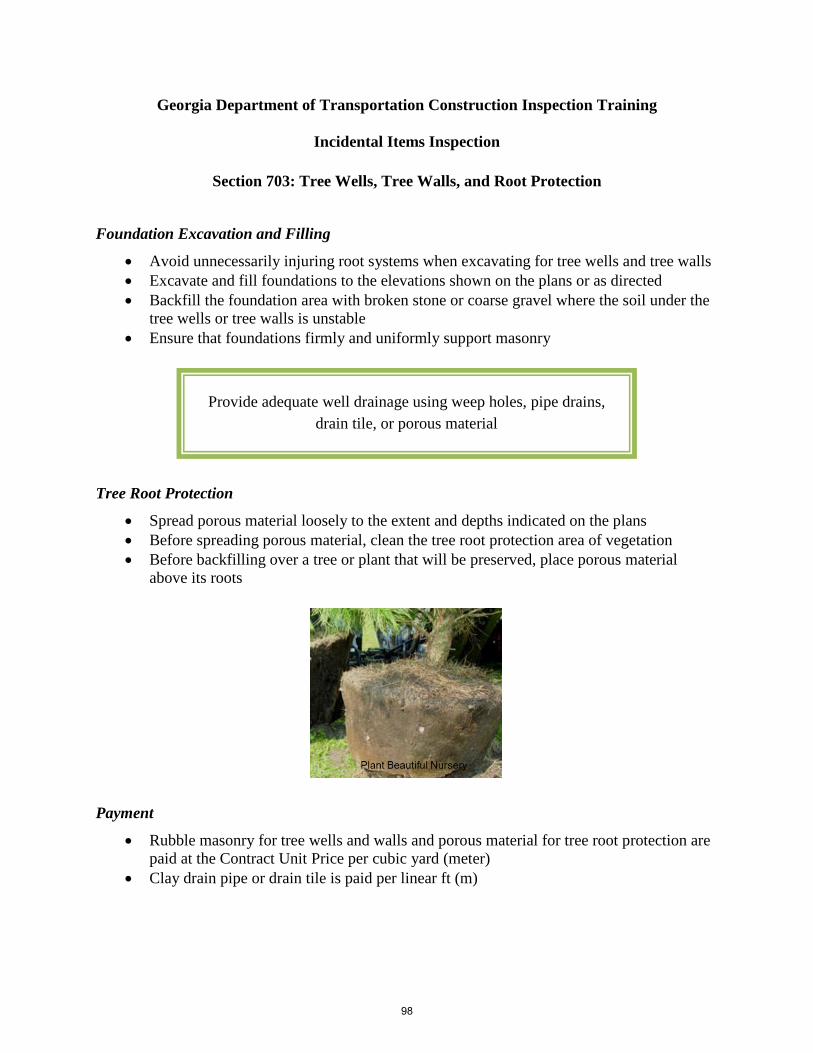
Georgia Department of Transportation Construction Inspection Training
Incidental Items Inspection
Section 703: Tree Wells, Tree Walls, and Root Protection
Foundation Excavation and Filling
• Avoid unnecessarily injuring root systems when excavating for tree wells and tree walls • Excavate and fill foundations to the elevations shown on the plans or as directed • Backfill the foundation area with broken stone or coarse gravel where the soil under the
tree wells or tree walls is unstable • Ensure that foundations firmly and uniformly support masonry
Tree Root Protection
• Spread porous material loosely to the extent and depths indicated on the plans • Before spreading porous material, clean the tree root protection area of vegetation • Before backfilling over a tree or plant that will be preserved, place porous material
above its roots
Payment
• Rubble masonry for tree wells and walls and porous material for tree root protection are paid at the Contract Unit Price per cubic yard (meter)
• Clay drain pipe or drain tile is paid per linear ft (m)
Provide adequate well drainage using weep holes, pipe drains, drain tile, or porous material
98
jsungail
Text Box
Georgia Department of Transportation Construction Engineering Inspection Training

Related Specifications
Section Title 834 842 893
Masonry Materials Clay Pipe Miscellaneous Planting Materials
99

Georgia Department of Transportation Construction Inspection Training
Incidental Items Inspection
Section 705: Transplanting Trees
Trunk and Branch Protection
• Protect trunks and branches from breaks or bruises • Spray trees in leaf with an approved antidesiccant before digging
Pruning
• Prune trees before transplanting as directed by the Engineer • Remove broken or badly bruised branches with a clean cut
Securing Roots
• Dig trees to secure as many roots as possible • Maintain a tight, firm ball during the moving operations
Excavating
• Excavate trees and tree pits • Use the excavated material to backfill the pits from
which the existing trees were removed Placing Trees in Pits
• Place transplanted trees into the new pits • Backfill voids between the ball and the pit with clean,
washed sand and then tamp • Thoroughly water the sand with a root feeder or water needle
Applying Topsoil and Mulch
• Apply plant topsoil to the transplanted tree according to plan details • Mulch a minimum 6-ft diameter tree pit with 3 in. (75 mm) of mulching material
Payment
• Transplanting trees is paid at the Contract Unit Price
Stake or anchor trees according to planting details
100
jsungail
Text Box
Georgia Department of Transportation Construction Engineering Inspection Training

Related Specifications
Section Title 891 893
Fertilizers Miscellaneous Planting Materials
101

Georgia Department of Transportation Construction Inspection Training
Incidental Items Inspection
Section 708: Plant Topsoil
General Requirements
• Only plant topsoil on slopes where the gradient is 3:1 or flatter • Scarify the designated areas 6–8 in. deep • Place the soil shortly before the grassing operations • Mix the plant topsoil, lime, and first application of fertilizer with the underlying soil • Spread and smooth the topsoil uniformly
Plant Topsoil Obtained from the Work
• Strip and stockpile the topsoil in suitable locations in advance of grading operations • Just before grassing, remove the plant topsoil from the stockpile and spread it over the
designated areas
• Use the surplus material as additional plant topsoil material if directed by the Engineer • Use the surplus material left in the stockpiles to maintain the Item or to fill washes that
occur within a reasonable haul distance • Remove or dress down the remaining material as directed by the Engineer
Payment
• Plant topsoil, eligible for payment, is paid at the Contract Unit Price per cubic yard (meter)
Place topsoil and complete the grassing within specified seasonal limits
102
jsungail
Text Box
Georgia Department of Transportation Construction Engineering Inspection Training

Related Specifications
Section Title 106 107 893
Control of Materials Legal Regulations and Responsibility to the Public Miscellaneous Planting Materials
103

Georgia Department of Transportation Construction Inspection Training
Incidental Items Inspection
Section 711: Turf Reinforcement Matting
Turf Reinforcement Matting (TRM) Installation
• Do not use in areas where rock crops out • Install mainly in ditches • Cut a transverse trench 6-in. wide × 9-in. deep at the ends of the TRM • Cut longitudinal, 4-in. deep anchor slots along each side of the TRM along the full
length of the ditch
• Bury the edges • Roll out the center strip of TRM starting at the lower end of the ditch • Overlap the ends of each TRM roll 3 ft (1 m) with the upslope mat on top • Backfill, compact, and dress the longitudinal anchor slots
Payment
• TRM is paid at the Contract Price per square yard (meter)
104
jsungail
Text Box
Georgia Department of Transportation Construction Engineering Inspection Training

Related Specifications
Section Title 700 Grassing
105

Georgia Department of Transportation Construction Inspection Training
Incidental Items Inspection
Section 712: Fiberglass Blanket
Mat Placement
• Dig a 9-in. deep anchor slot across the upgrade end of the site • Place the initial 12 in. of blanket in the anchor slot • Backfill and solidly tamp the slot • Unroll the blanket in the direction of water flow, keeping the blanket in contact with the
soil over the entire area • Overlap adjacent strips at least 2 in. • Overlap adjoining ends at least 6 in., with the upstream section on top
Mat Stapling
• Drive staples vertically into the ground approximately 1 yd (1 m) apart on each side of the blanket
• Drive one row in the center alternately spaced between each side staple • Place the edge staples in the 2-in. (50 mm) overlap • At the end of each mat, place staples in a row spaced approximately 12 in. apart
Note: The Contractor may apply an asphalt emulsion instead of staples to anchor the blanket
Place the mat or blanket within 24 hours after the area has been planted but before any rain or watering
The Engineer may specify additional staples or check slots in waterways
106
jsungail
Text Box
Georgia Department of Transportation Construction Engineering Inspection Training

Payment
• Fiberglass blanket is paid at the Contract Price per square yard (meter) Related Specifications
Section Title 700 822
Grassing Emulsified Asphalt
107

Georgia Department of Transportation Construction Inspection Training
Incidental Items Inspection
Section 713: Organic and Synthetic Material Fiber Blanket
Definitions Straw Blanket: A machine-produced blanket of clean, weed-free, consistently
thick straw from agricultural crops Excelsior Blanket: A machine-produced mat of curled wood excelsior Coconut Fiber Blanket: A machine-produced blanket of 100% coconut fiber evenly
distributed over the entire blanket Wood Fiber Blanket–Type 1: A machine-produced blanket manufactured with reprocessed
wood fibers to a consistent thickness Wood Fiber Blanket–Type 2: A hydraulically applied bonded fiber matrix that, upon drying,
adheres to the soil in a form of a continuous 100% coverage, biodegradable erosion control blanket
Synthetic Fiber Blanket: A machine-produced uniform blanket of ultraviolet degradable
polypropylene staple fibers reinforced with ultraviolet degradable polypropylene netting
Blanket Placement
• Place vertically on slopes beginning at the top of the slope and extending to the bottom • Place the blanket within 24 hours after planting and before rain or watering • Unroll the blanket with the netting on top and the fibers contacting the soil over the
slope • Overlay the joint 4 in. and staple through the joint
108
jsungail
Text Box
Georgia Department of Transportation Construction Engineering Inspection Training

• Overlap the ends of the blanket at least 6 in. with the upgrade section on top, and staple through the overlap
Stapling
• Drive staples vertically into the ground to anchor the plastic mesh • Place the staples approximately 2 yd (2 m) apart on each side of the blanket and add one
row in the center alternately spaced between each side staple • Where the blankets lay side to side, place each staple so that half of the staple anchors
mesh from each blanket Payment
• Material fiber blankets are paid at the Lump Sum Contract Unit Price bid
Horizontal installation of the blankets is not permitted
109

Georgia Department of Transportation Construction Inspection Training
Incidental Items Inspection
Section 714: Jute Mesh Erosion Control
Mesh Placement
• Roll the mesh out in the direction of flow unless the downstream end section connects to a drainage structure or paved ditch
• Anchor the mesh in a 6-in. deep trench adjacent to the structure • Overlap adjacent strips by at least 6 in. • Overlap adjoining ends by at least 6 in.
• For all overlaps, place the upstream section on top • Use a Type 2 check slot at the downstream end of the jute mesh that does not connect • Apply the jute mesh without stretching • Do not allow workers to walk directly on the seedbed before or after applying the mesh • Bury the up-channel end of each installation in a narrow, 6-in. deep trench • After burying the mesh, backfill, tamp, and staple the trench
Mat Stapling
• Staple along each edge • Staple each row along the middle • Space staples no more than 3 ft (1 m) apart in each row • Space the staples in the middle row alternately with those at the edges • Ensure that staples remain flush with the ground
Lay the mesh evenly but loosely on the soil surface
110
jsungail
Text Box
Georgia Department of Transportation Construction Engineering Inspection Training

Rolling
• Firmly embed the mesh in the soil by tamping or rolling • Secure mesh that bridges over soil surface irregularities with extra staples to provide
overall contact with the soil Related Specifications
Section Title 106 Control of Materials
111
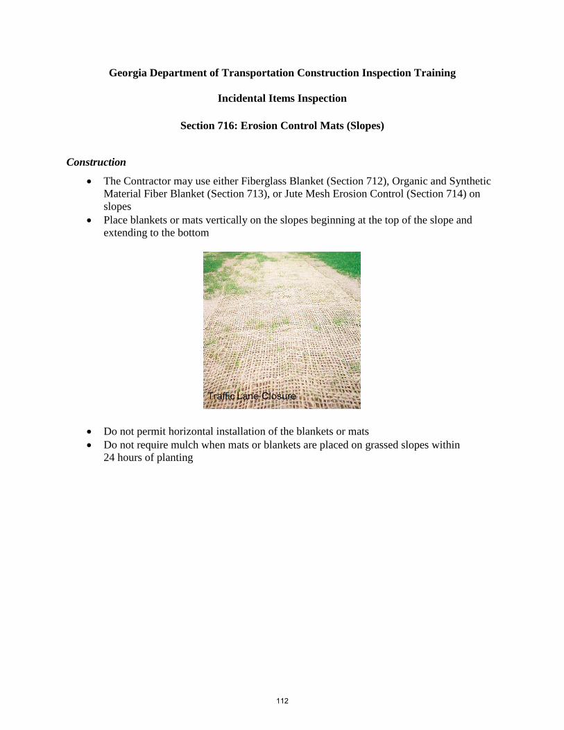
Georgia Department of Transportation Construction Inspection Training
Incidental Items Inspection
Section 716: Erosion Control Mats (Slopes)
Construction
• The Contractor may use either Fiberglass Blanket (Section 712), Organic and Synthetic Material Fiber Blanket (Section 713), or Jute Mesh Erosion Control (Section 714) on slopes
• Place blankets or mats vertically on the slopes beginning at the top of the slope and extending to the bottom
• Do not permit horizontal installation of the blankets or mats • Do not require mulch when mats or blankets are placed on grassed slopes within
24 hours of planting
112
jsungail
Text Box
Georgia Department of Transportation Construction Engineering Inspection Training

Georgia Department of Transportation Construction Inspection Training
Incidental Items Inspection
Section 718: Wood Fiber
Construction
• Apply enough materials to cover the ground evenly and thoroughly as directed by the Engineer
• Use hydraulic equipment to apply a homogeneous water slurry that includes the proper amounts and kind of seed and fertilizer
• Mix the slurry during application
113
jsungail
Text Box
Georgia Department of Transportation Construction Engineering Inspection Training

Georgia Department of Transportation Construction Inspection Training
Incidental Items Inspection
Section 719: Silt Filter Bag
Construction
• Place a silt filter bag on a #57 stone gravel bed sloped to ensure that the filtered water will exit at the desired location
• Extend the pump hose past the inlet opening to ensure that the silt-laden water will discharge in the center of the bag
• Ensure that the seal between the inlet and hose is watertight • When the filter bag is full of silt and cannot readily pass more water, use a new filter bag • If approved by the Engineer, bury the full filter bag on site or remove the top section of
fabric and then seed the exposed filtrate
Payment
• Silt filter bags are paid at the Contractor Unit Price per each
Choose an exit location to prevent erosion
114
jsungail
Text Box
Georgia Department of Transportation Construction Engineering Inspection Training

Georgia Department of Transportation Construction Inspection Training
Incidental Items Inspection
Section 720: Triangular Silt Barrier
Construction
• Excavate a trench 4–6 in. deep using equipment such as a trenching machine or motor grader; or, if equipment cannot be operated on site, excavate by hand
• Secure the edge of the fabric into the trench with wire staples • Install the fabric in the trench so that 4–6 in. of fabric is against the side of the trench
with 2–4 in. of fabric across the bottom in the upstream direction
• Backfill the trench and compact it so that no flow can pass under the barrier • Where the individual sections of triangular silt barrier meet, fix the fabric to the ground
with wire staples at each joint location and at each end of the barrier • The Engineer may increase, decrease, or eliminate the quantity of triangular silt barrier
Related Specifications
Section Title 106 Control of Materials
Triangular silt barrier may be substituted for baled straw
115
jsungail
Text Box
Georgia Department of Transportation Construction Engineering Inspection Training

References www.pgwa.org www.hanesgeo.com www.paturnpike.com www.arcadiasbest.com www.engr.wisc.edu www.fhwa.dot.gov www.gic-edu.com www.engr.psu.edu www.mragta.com www.michiganhighways.org www.wsdot.wa.gov www.rtnroofing.com www.rtnroofing.com theconstructor.org www.wisdotresearch.wi.gov www.constructionprojectinspection.com en.vsl.cz http://mutcd.fhwa.dot.gov www.seattle.gov www.architecturejt.wordpress.com www.tmcrebar.com www.steelconstruction.info www.americanconcrete.org www.harrissupplysolutions.com www.kingcounty.gov www.gratesolutions.net www.cogginsfence.com www.fhwa.dot.gov www.gallery.ptcsb.com www.smallwater.wordpress.com www.sunlive.co.nz co.ross.oh.us www.123rf.com www.modot.org alphaconstruction.biz www.johnweeks.com www.mrwallpaper.com www.hendersonconstructionfabrics.com www.apoc.com www.acpapplied.com www.sealtec.ca www.hendersonconstructionfabrics.com www.libn.com www.irjci.blogspot.com www.redrundrain.wordpress.com epg.modot.org www.acrow.com www.wildish.com www.edawilson.com www.minnesota.publicradio.org www.gimrock.com www.saint-gobain-pam-cast-iron.com www.ccppa.org www.kanapipeline.com www.sunnysteel.com www.pomonapipeproducts.com www.metalculverts.com www.metal-culvert.com www.pabreschjr.com www.permo-liner.com www.fusecon.com www.newburymarket.com www.hiwtc.com www.geosyntheticsmagazine.com www.tnepsc.org www.cecilscd.com www.picstopin.com www.algacn.com www.directindustry.com www.fhwa.dot.gov www.flintmarine.com www.troweltradessupply.com www.kaneva.com www.4shared.com www.aggregatetechnologies.com www.huckbody.com www.cenews.com www.turnermanholerisers.com www.4eastcounty.com www.ace-fla.com www.garverusa.com www.tekyontunel.com www.nickolboring.com www.fandbts.co.uk www.foundationsupportworks.com www.wsdot.wa.gov
116