Geophysical site investigation survey WFZ Borssele
36
Transcript of Geophysical site investigation survey WFZ Borssele


Geophysical site investigation survey WFZ Borssele – WFS 1 & 2
A sneak preview
RVO Workshop WFZ Borssele
The Hague, March 30th 2015
Dr. Sybrand van Beijma, Reporting coordinator
Gert-Jan Siepel, operations manager

Contents
• Introduction Deep BV
• Project outline
• Results
• Q&A

Introduction: Deep BV profile
• Deep BV: – Our mission is to measure and visualize everything in 4D underneath the water
surface. We aim to be the specialist in the field of hydrographical and geophysical survey, utilizing our expertise in a wide range of practices
– Privately owned
– Project portfolio 1/3 national, 2/3 globally; staff of 55 (mainly IHO cat A – Msc)
– ISO 9001 and OHSAS 18001 certified
– We take full survey responsibility with own staff, equipment and vessels
– We love to cooperate with our clients, with client’s role: Challenge our expertise!
– The result: a tailor made solution, comprehensively presenting reliable data for our client’s needs
Introduction: Deep BV markets

Introduction: services renewable
• Pre concession site survey
• Route design
• Metocean site monitoring
• Pre installation site survey
• UXO/archeological campaign
• Survey services during installation; as-laid & as-built
• QA survey on completion to confirm Depth of Burial cables
• O&M survey: cable trajectories, scour monitoring & fault finding
Introduction: renewable experience
• Over 10 years of offshore wind experience in EU waters
• Contributed to: – NL: OWEZ, PAWP, Luchterduinen, Gemini, Borssele, Westermeerwind
– UK: Gunfleet Sands, London Array, Lincs
– GE: Alpha Ventus, Anholt, Borkum Riffgrund, Butendiek, Helwin, Riffgat
– BE: Thornton Bank, Belwind
– DK: Hornsrev2
Project outline
• Time schedule
• Geographical setting
• Available info
• Objective
• Scope of work

Project outline: time schedule
• 2014 Sep 5th: RFQ framework agreement (FA)
• 2014 Nov 14th: award FA
• 2014 Dec 4th:RFQ specific agreement (SA)
• 2014 Dec 19th: award SA
• 2014 Dec 29th: signing SA
• 2015 Jan 12th: start mobilisation
• 2015 Jan 16th: start survey operations
• 2015 Feb 15th: end survey operations
• 2015 Mar 3rd: issue draft report
• 2015 Mar 27th: issue final report
• 2015 Mar 30th: sneak preview

Project outline: geographical setting

Project outline: available info
• Desktop studies – Geological desk study (ediGEO/GisSense/Crux Engineering)
– Morphodynamical desk study (Deltares)
– UXO desk study (REASeuro)
Project outline: objective
• General – Improve geological/geotechnical understanding of the site
– Obtain geophysical information, suitable to prepare geotechnical investigations
– Obtain geophysical information, suitable to progress design for concession tender phase
– Part of full info package in concession tendering
– Input for update of the desktop studies

Project outline: objective
• Deliverables 1. Bathymetric chart
2. Mapping and description of objects
3. Mapping pipelines/cables
4. Geological model: isopach charts and sections
5. Geological engineering hazards
6. Input geotechnical campaign

Project outline: scope of work
• High resolution bathymetric survey – DTM, seabed classification, objects and pipelines/cables on the seabed
• High resolution side scan sonar survey – Objects, seabed classification and pipelines/cables on the seabed
• High resolution magnetometer survey – Large ferromagnetic objects and pipelines/cables on/in the seabed
• High resolution seismic profiling survey – HF SBP system (0-10m) & LF MC sparker (0-100m)
– Combined geological model with overlapping coverage
– Geohazards and input geotechnical campaign
Results
• All data from different techniques have been cross-referenced
• QA/review on behalf of client: – Fieldwork: RPS group
– Processing: RPS group and Reynolds International
– Reporting: RPS group, Reynolds International and DNV-GL
• Data quality is excellent!

Results: objective 1: bathymetric DTM • Complex pattern with parallel sandbanks
with general stretching SW-NE
• Four sandbanks crossing both WFS-1 and WFS-2: from sea to shore Buitenbank 2, Buitenbank 3, Schaar and Rabsbank
• Superimposed sand waves generally stretching NW-SE.
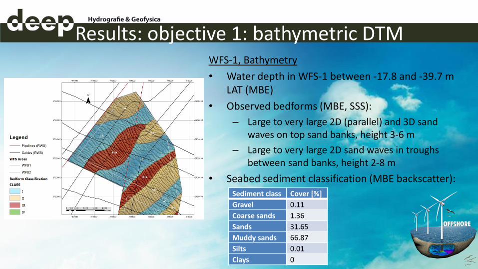
Results: objective 1: bathymetric DTM WFS-1, Bathymetry
• Water depth in WFS-1 between -17.8 and -39.7 m LAT (MBE)
• Observed bedforms (MBE, SSS):
– Large to very large 2D (parallel) and 3D sand waves on top sand banks, height 3-6 m
– Large to very large 2D sand waves in troughs between sand banks, height 2-8 m
• Seabed sediment classification (MBE backscatter):
Sediment class Cover [%]
Gravel 0.11
Coarse sands 1.36
Sands 31.65
Muddy sands 66.87
Silts 0.01
Clays 0
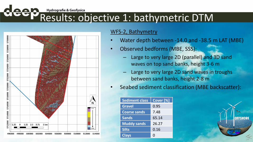
Results: objective 1: bathymetric DTM WFS-2, Bathymetry
• Water depth between -14.0 and -38.5 m LAT (MBE)
• Observed bedforms (MBE, SSS):
– Large to very large 2D (parallel) and 3D sand waves on top sand banks, height 3-6 m
– Large to very large 2D sand waves in troughs between sand banks, height 2-8 m
• Seabed sediment classification (MBE backscatter):
Sediment class Cover [%]
Gravel 0.95
Coarse sands 7.48
Sands 65.14
Muddy sands 26.27
Silts 0.16
Clays 0

Results: objective 2: seabed objects WFS-1 & WFS-2, Wrecks
• According to the Wrakkenregister two wrecks located in WFS-1 and two wrecks located in WFS-2
• In WFS-1 wreck 1738 detected, wreck still identifiable as ship
• In WFS-2 wreck 3658 detected, visible as debris

Results: objective 2: seabed objects WFS-1, Other objects (MBE, SSS, MAG)
• In WFS-1 110 contacts not associated with wrecks, pipelines or cables detected.
• Contacts split out by survey technique:
SSS
only
MAG
only
SSS/MAG SSS/MBE SSS/MAG/MBE Total
29 72 0 9 0 110

Results: objective 2: seabed objects WFS-2, Other objects (MBE, SSS, MAG)
• In WFS-2 200 contacts not associated with wrecks, pipelines or cables detected.
• Contacts split out by survey technique:
SSS
only
MAG
only
SSS/MAG SSS/MBE SSS/MAG/MBE Total
94 90 3 12 1 200
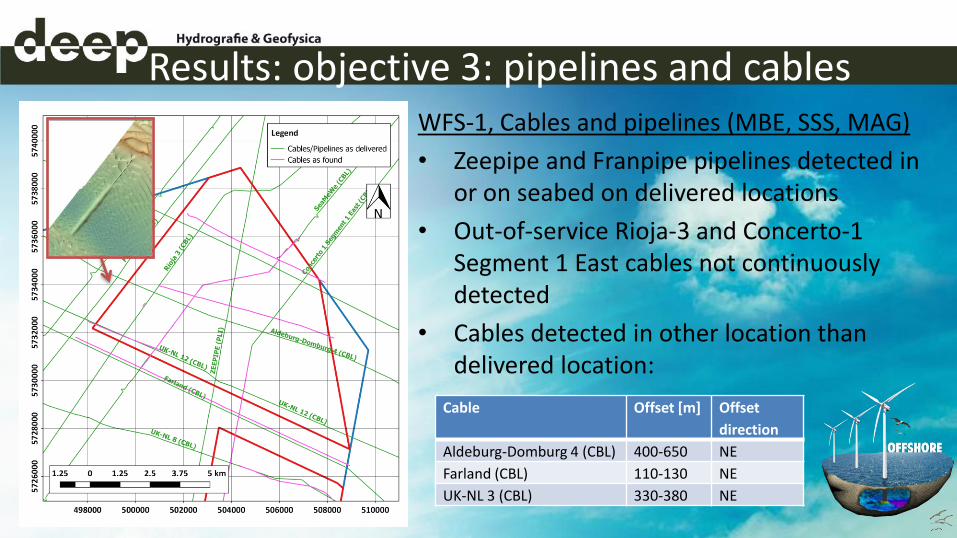
Results: objective 3: pipelines and cables WFS-1, Cables and pipelines (MBE, SSS, MAG)
• Zeepipe and Franpipe pipelines detected in or on seabed on delivered locations
• Out-of-service Rioja-3 and Concerto-1 Segment 1 East cables not continuously detected
• Cables detected in other location than delivered location:
Cable Offset [m] Offset
direction
Aldeburg-Domburg 4 (CBL) 400-650 NE
Farland (CBL) 110-130 NE
UK-NL 3 (CBL) 330-380 NE
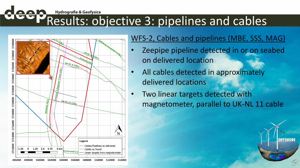
Results: objective 3: pipelines and cables WFS-2, Cables and pipelines (MBE, SSS, MAG)
• Zeepipe pipeline detected in or on seabed on delivered location
• All cables detected in approximately delivered locations
• Two linear targets detected with magnetometer, parallel to UK-NL 11 cable

Results: objective 4: geological model Geological framework
• Background information from literature and desk study geology used
• Interpretation of MCS seismic data shows that two main geological units can be identified: – Horizontally stratified marine and coastal
Tertiary deposits (U1 – U5)
– Shallow marine and fluvial Quaternary deposits (U6 & U7)

Results: objective 4: geological model Seismic interpretation Tertiary deposits (MCS)
• Dongen Formation (U1 & U2). Maximum observed thickness 210 metres. Characterised by slightly calcareous clays with intercalated sand sequences
• Tongeren Formation (U3 & U4). Observed thickness between 10 and 130 metres. Characterised by fine to very fine sand at the base, alternating clay and sand layers at the top
• Rupel Formation (U5). Observed thickness between 0 and 30 metres. Characterised by variation of marine clays and sand beds
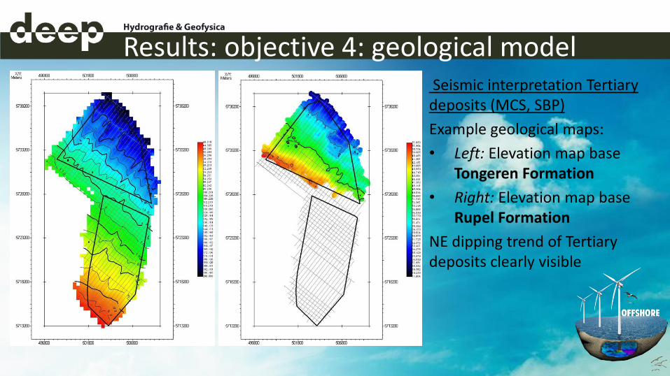
Results: objective 4: geological model Seismic interpretation Tertiary deposits (MCS, SBP)
Example geological maps:
• Left: Elevation map base Tongeren Formation
• Right: Elevation map base Rupel Formation
NE dipping trend of Tertiary deposits clearly visible

Results: objective 4: geological model
Seismic interpretation Quaternary deposits (MCS, SBP)
• Pleistocene deposits (U6). Interpreted as combination of Eem, Brown Bank and Kreftenheye Formations. Observed thickness 0- 60 metres. Characterised by infilled channels consisting of sand with patches of clay or gravel. Limited spatial continuity
• Holocene deposits (U7). Observed thickness 1-13 metres. Interpreted as combination of Buitenbanken and Bligh Bank Formations. Characterised by fine to coarse sand.
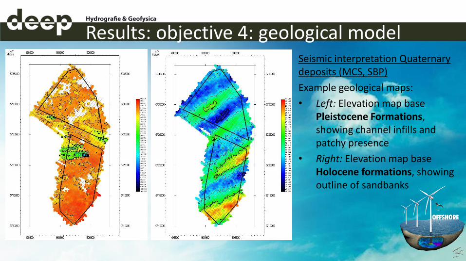
Results: objective 4: geological model Seismic interpretation Quaternary deposits (MCS, SBP)
Example geological maps:
• Left: Elevation map base Pleistocene Formations, showing channel infills and patchy presence
• Right: Elevation map base Holocene formations, showing outline of sandbanks

Results: objective 5: geo-hazards WFS-1 & WFS-2, Shallow geo-hazards in U6 and U7 (SBP)
• Denser material in top U6, scattered in WFS-1, more concentrated in WFS-2
• Shallow paleo-channel infill in top U6 in WFS-2

Results: objective 5: geo-hazards WFS-1 & WFS-2, Channel infills in U6 (MCS)
• Channel infill deposits, associated with fluvial erosion and scour hollow formation in Pleistocene.
• Thickness up to 60 metres at scour hollows, filled-in channel deposits up to 15 metres thick

Results: objective 5: geo-hazards WFS-1 & WFS-2, Gravel beds in U4 and U6 (MCS)
• Visible as point diffractors in seismic data
• Found widespread in U6 (coinciding with SBP interpretation), along patches along specific horizons in U4
• Concentration in U4 in central area of survey area on boundary between WSF-1 and WFS-2

Results: objective 5: geo-hazards WFS-1, Liquefaction structures in U5 (MCS)
• Visible as sharp deformation features
• Phenomenon probably of Quaternary age, it does affect lower boundary of U6
• Only observed very localised in WFS-1

Results: objective 5: geo-hazards WFS-2, Shallow gas and organic deposits in U3 (MCS)
• Visible as reflectors with strong amplitude of reverse polarity
• No indication of shallow gas fluid flow system
• Only observed in WFS-2
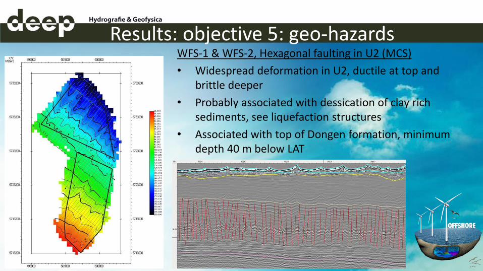
Results: objective 5: geo-hazards WFS-1 & WFS-2, Hexagonal faulting in U2 (MCS)
• Widespread deformation in U2, ductile at top and brittle deeper
• Probably associated with dessication of clay rich sediments, see liquefaction structures
• Associated with top of Dongen formation, minimum depth 40 m below LAT

Results: objective 6: proposed boreholes
• Based on interpretation of seismic data and identification of geo-hazards, borehole locations have been proposed
• The final geotechnical borehole plan is further developed by RVO and the geotechnical contractor
• Results from the geotechnical survey will be used to update and improve the geological model
Q&A
• Contact info Deep BV services: – Jurgen Beerens, commercial manager [email protected]
• Questions?