GEOPAK V8i(SELECTseries 2) - Virginia Department of ... · PDF fileDO NOT DISTRIBUTE -...
248
DO NOT DISTRIBUTE - Printing for Student Use is Permitted Company: Virginia DOT Class Date: 20-May-2013 VDOT GEOPAK Drainage GEOPAK V8i(SELECTseries 2) Bentley Institute Course Guide TRN017150-1/0002
Transcript of GEOPAK V8i(SELECTseries 2) - Virginia Department of ... · PDF fileDO NOT DISTRIBUTE -...

DO N
OT
DIST
RIBU
TE -
Prin
ting
for S
tude
nt U
se is
Per
mitt
ed
Co
mpa
ny: V
irgin
ia D
OT
C
lass
Dat
e: 2
0-M
ay-2
013
VDOT GEOPAK Drainage GEOPAK V8i(SELECTseries 2)
Bentley Institute Course Guide
TRN017150-1/0002
DO N
OT
DIST
RIBU
TE -
Prin
ting
for S
tude
nt U
se is
Per
mitt
ed
Co
mpa
ny: V
irgin
ia D
OT
C
lass
Dat
e: 2
0-M
ay-2
013
November 2011
Copyright © 2011 Bentley Systems, Incorporated
Trademarks AccuDraw, Bentley, the “B” Bentley logo, MDL, MicroStation and SmartLine are registered trademarks; PopSet and Raster Manager are trademarks; Bentley SELECT is a service mark of Bentley Systems, Incorporated or Bentley Software, Inc.
AutoCAD is a registered trademark of Autodesk, Inc.
All other brands and product names are the trademarks of their respective owners.
Patents United States Patent Nos. 5,8.15,415 and 5,784,068 and 6,199,125.
Copyrights ©2000-2011 Bentley Systems, Incorporated.
MicroStation ©1998 Bentley Systems, Incorporated.
All rights reserved.
DO N
OT
DIST
RIBU
TE -
Prin
ting
for S
tude
nt U
se is
Per
mitt
ed
Co
mpa
ny: V
irgin
ia D
OT
C
lass
Dat
e: 2
0-M
ay-2
013
3 Table of Contents
Copyright © November-2011 Bentley Systems Incorporated
Table of Contents
Table of Contents 3
Digital Terrain Modeling for Drainage Design and Analysis 1-1
OBJECTIVES ...............................................................................................1-1 INTRODUCTION .........................................................................................1-1
ACCESSING ................................................................................................1-1 SETTINGS ..................................................................................................1-1 EXTRACT GRAPHICS ...................................................................................1-2
BUILD TOOLS .............................................................................................1-3 REPORTS ...................................................................................................1-5
UTILITIES ...................................................................................................1-5 LOAD DTM FEATURES................................................................................1-6 EDIT TOOLS ...............................................................................................1-7
TRIANGULATION .......................................................................................1-8 DISPLAY FEATURES ....................................................................................1-8
LAB EXERCISE: DIGITAL TERRAIN MODELING .............................................1-9 PROPOSED CROSS SECTIONS TO DTM......................................................1-11 LAB EXERCISE: PROPOSED CROSS SECTIONS TO DTM...............................1-12
Drainage Analysis 2-1
OBJECTIVES ...............................................................................................2-1 INTRODUCTION .........................................................................................2-1
ACCESSING ................................................................................................2-1 ANALYSIS TOOLS .......................................................................................2-1
ANALYSIS TOOLS: DRAINAGE .....................................................................2-2 LAB EXERCISE: ANALYSIS OF THE PROPOSED DTM .....................................2-5 LAB EXERCISE: PLOTTING PROFILE ELEVATIONS ALONG THE CENTERLINE .........................................................................2-11 LAB EXERCISE: SETTING UP LAND USE AREAS ..........................................2-14
Starting a Drainage Project 3-1
OBJECTIVES ...............................................................................................3-1
DO N
OT
DIST
RIBU
TE -
Prin
ting
for S
tude
nt U
se is
Per
mitt
ed
Co
mpa
ny: V
irgin
ia D
OT
C
lass
Dat
e: 2
0-M
ay-2
013
Table of Contents
4 Table of Contents
Copyright © November-2011 Bentley Systems Incorporated
GEOPAK DRAINAGE ...................................................................................3-1 DRAINAGE COMPONENTS .........................................................................3-2
MAIN MENU BAR ......................................................................................3-3 PROJECT MENU SELECTIONS .....................................................................3-3 COMPONENT MENU SELECTIONS ..............................................................3-4
NETWORK MENU SELECTIONS ...................................................................3-4 REPORTS MENU SELECTIONS .....................................................................3-4
TOOLS MENU SELECTIONS.........................................................................3-5 GENERAL DESIGN PROCESS FOR STORM DRAINS .......................................3-5
VDOT VBA APPLICATIONS ..........................................................................3-5 ACCESSING GEOPAK DRAINAGE.................................................................3-6 LAB EXERCISE: OPENING A NEW GEOPAK DRAINAGE PROJECT ....................................................................................................3-6
GEOPAK Drainage Project Preferences 4-1
OBJECTIVES ...............................................................................................4-1
INTRODUCTION .........................................................................................4-1 UNITS ........................................................................................................4-2 PROJECT COMPONENTS ............................................................................4-3
RAINFALL PARAMETERS ............................................................................4-5 LAND USE OPTIONS ...................................................................................4-6
FREQUENCY OPTIONS ...............................................................................4-7 INTENSITY OPTIONS ..................................................................................4-8 JUNCTION LOSSES .....................................................................................4-9
INLET OPTIONS........................................................................................4-10 NODE OPTIONS .......................................................................................4-12
LINK OPTIONS .........................................................................................4-13 PROFILE OPTIONS....................................................................................4-15
PLAN SYMBOLOGY ..................................................................................4-16 UPDATES .................................................................................................4-16 SAVE OPTIONS ........................................................................................4-17
PRINTING THE PROJECT PREFERENCES ....................................................4-17 LAB EXERCISE: PROJECT PREFERENCES ....................................................4-18
DO N
OT
DIST
RIBU
TE -
Prin
ting
for S
tude
nt U
se is
Per
mitt
ed
Co
mpa
ny: V
irgin
ia D
OT
C
lass
Dat
e: 2
0-M
ay-2
013
Table of Contents
5 Table of Contents
Copyright © November-2011 Bentley Systems Incorporated
VDOT Drainage Library 5-1
OBJECTIVES ...............................................................................................5-1 INTRODUCTION .........................................................................................5-1
RAINFALL ITEMS ........................................................................................5-2 LAB EXERCISE: UNDERSTANDING THE DRAINAGE LIBRARY ....................................................................................................5-3
LAND USE ITEMS .......................................................................................5-4 NODE ITEMS..............................................................................................5-6
LINK ITEMS ................................................................................................5-8 SPREAD SECTION .....................................................................................5-11
Advanced Storm Sewer Design 6-1
OBJECTIVES ...............................................................................................6-1 DRAINAGE AREAS: INTRODUCTION ...........................................................6-1 DRAINAGE AREA: DEFINITION ...................................................................6-2
DRAINAGE AREA: SUB AREAS ....................................................................6-4 DRAINAGE AREA: COMPUTATION..............................................................6-5
NODES: INTRODUCTION ............................................................................6-5 NODE: PROPERTIES ...................................................................................6-6 NODE: LOCATION ......................................................................................6-7
NODE: SPREAD CRITERIA ...........................................................................6-9 NODE: ELEVATIONS .................................................................................6-12
MINIMUM AND MAXIMUM DEPTH AT NODES DEFINITION .............................................................................................6-14 NODE: JUNCTION LOSS ............................................................................6-15
NODE: DISCHARGE OPTIONS ...................................................................6-15 NODE: COMPUTATIONS ..........................................................................6-16
LAB EXERCISE: DRAINAGE DESIGN ...........................................................6-18 DELINEATING DRAINAGE AREAS ..............................................................6-22 COMPLETE THE INLET LOCATIONS ...........................................................6-30
LINKS: INTRODUCTION ............................................................................6-30 LINK CONFIGURATION DIALOG: INTRODUCTION .....................................6-32
LINK CONFIGURATION DIALOG: DEFINITION ............................................6-32 LINK CONFIGURATION DIALOG: CONDITIONS ..........................................6-36 LINK CONFIGURATION DIALOG: CONSTRAINTS ........................................6-37
DO N
OT
DIST
RIBU
TE -
Prin
ting
for S
tude
nt U
se is
Per
mitt
ed
Co
mpa
ny: V
irgin
ia D
OT
C
lass
Dat
e: 2
0-M
ay-2
013
Table of Contents
6 Table of Contents
Copyright © November-2011 Bentley Systems Incorporated
LINK CONFIGURATION DIALOG: COMPUTATION ......................................6-39 LAB EXERCISE: LINKS ...............................................................................6-40
NETWORKS: INTRODUCTION ..................................................................6-42 NETWORK CONFIGURATION DIALOG .......................................................6-44 LAB EXERCISE: NETWORKS ......................................................................6-46
VDOT DRAINAGE INPUT ..........................................................................6-47 LAB EXERCISE: CREATE DRAINAGE DATA WITH VDOT DRAINAGE INPUT FORM ..........................................................................6-49 REPORTS: INTRODUCTION .......................................................................6-51 VDOT STORM SEWER TABULATION .........................................................6-52
VDOT SPREAD ANALYSIS TABULATION.....................................................6-54 LAB EXERCISE: CREATE VDOT STORM SEWER TABULATION SHEET ................................................................................6-56 LAB EXERCISE: CREATE VDOT STORM SEWER TABULATION SHEET ................................................................................6-57
Service Utilities and Utility Conflicts 7-1
OBJECTIVES ...............................................................................................7-1 DRAINAGE PROFILES: INTRODUCTION .......................................................7-1
REGISTRATION ..........................................................................................7-3 DISPLAY PROPERTIES .................................................................................7-3 DRAINAGE INFORMATION .........................................................................7-4
GRID AND LABELS ......................................................................................7-4 LINK PROFILE .............................................................................................7-5
PREFERENCES ............................................................................................7-6 MISCELLANEOUS UTILITIES ........................................................................7-6
LAB EXERCISE: PROFILE DESIGN .................................................................7-8 VDOT TEST HOLE UTILITY APPLICATION ...................................................7-10 VDOT DRAINAGE PROFILE LABELER .........................................................7-13
Plans Preparation 8-1
OBJECTIVES ...............................................................................................8-1 LAB EXERCISE: SKETCH OF THE GEOPAK DRAINAGE NETWORK .................................................................................................8-1 LAB EXERCISE: UPDATING THE DESIGN TO VDOT CADD STANDARDS ....................................................................................8-3
PLAN VIEW LABELING ................................................................................8-5
DO N
OT
DIST
RIBU
TE -
Prin
ting
for S
tude
nt U
se is
Per
mitt
ed
Co
mpa
ny: V
irgin
ia D
OT
C
lass
Dat
e: 2
0-M
ay-2
013
Table of Contents
7 Table of Contents
Copyright © November-2011 Bentley Systems Incorporated
LAB EXERCISE: PLAN VIEW LABELING .........................................................8-6 AUTOMATED QUANTITIES .......................................................................8-13
OPERATIONAL MODES: COMPUTE...........................................................8-13 LAB EXERCISE: AUTOMATED PLAN VIEW QUANTITIES ............................................................................................8-16
VDOT DRAINAGE CROSS SECTIONS APPLICATIONS ..................................8-18 DRAINAGE PATTERN LINES ......................................................................8-18
DRAW DRAINAGE FEATURES IN CROSS SECTION......................................8-20 LAB EXERCISE: CREATING DRAINAGE CROSS SECTIONS ................................................................................................8-25
DRAINAGE SUMMARY .............................................................................8-31 LAB EXERCISE: DRAINAGE SUMMARY ......................................................8-31
VDOT DRAINAGE DESCRIPTIONS..............................................................8-33 LAB EXERCISE: DRAINAGE DESCRIPTIONS ................................................8-35
Culvert Design 9-1
OBJECTIVES ...............................................................................................9-1 INTRODUCTION .........................................................................................9-1 INVOKING THE CULVERT TOOL ..................................................................9-1
LAB EXERCISE: CULVERT DESIGN................................................................9-3
VDOT Bentley Community Group 10-1
OBJECTIVES .............................................................................................10-1
INTRODUCTION .......................................................................................10-1 LAB EXERCISE: JOIN THE BE COMMUNITY ................................................10-1
Class Project 11-1
OBJECTIVES .............................................................................................11-1 INTRODUCTION .......................................................................................11-1 PROJECT FILES .........................................................................................11-1
PROJECT COMPLETION ............................................................................11-2
Technical Reference 12-1
OBJECTIVES .............................................................................................12-1 THE RATIONAL METHOD .........................................................................12-1 INLET SPREAD COMPUTATIONS ...............................................................12-8
DO N
OT
DIST
RIBU
TE -
Prin
ting
for S
tude
nt U
se is
Per
mitt
ed
Co
mpa
ny: V
irgin
ia D
OT
C
lass
Dat
e: 2
0-M
ay-2
013
Table of Contents
8 Table of Contents
Copyright © November-2011 Bentley Systems Incorporated
CURB INLETS ON-GRADE .........................................................................12-8 CURB INLETS IN SAG CALCULATIONS .......................................................12-9
GRATE INLETS ON-GRADE CALCULATIONS ............................................. 12-10 GRATE INLETS IN SAG CALCULATIONS ................................................... 12-12 LINK HYDRAULIC COMPUTATIONS ......................................................... 12-14
LINK DESIGN CONSTRAINTS ................................................................... 12-15 HYDRAULIC GRADE LINE COMPUTATIONS ............................................. 12-17
HYDRAULIC GRADELINE ......................................................................... 12-17 SPECIAL CONSIDERATIONS .................................................................... 12-18
JUNCTION LOSS METHODOLOGIES ........................................................ 12-19 FREE SURFACE TRANSITION LOSSES....................................................... 12-19 PRESSURE FLOW TRANSITION LOSSES ................................................... 12-19
BEND LOSSES ........................................................................................ 12-20 CURVE LOSSES....................................................................................... 12-21
TERMINAL INLET /JUNCTION LOSS......................................................... 12-21 COMPLEX JUNCTIONS ........................................................................... 12-21 GEOPAK DRAINAGE WARNING MESSAGES ............................................ 12-24
PREFERENCES ........................................................................................ 12-24 AREAS ................................................................................................... 12-24
NODE: ................................................................................................... 12-24 LINK: ..................................................................................................... 12-25 NETWORK: ............................................................................................ 12-25
PROFILES ............................................................................................... 12-26 NAVIGATOR .......................................................................................... 12-26
ROUTING............................................................................................... 12-26 GEOPAK REPORT BUILDER VARIABLES ................................................... 12-27
AREA ..................................................................................................... 12-27 NODE .................................................................................................... 12-27 INLET..................................................................................................... 12-28
LINKS..................................................................................................... 12-30
DO N
OT
DIST
RIBU
TE -
Prin
ting
for S
tude
nt U
se is
Per
mitt
ed
Co
mpa
ny: V
irgin
ia D
OT
C
lass
Dat
e: 2
0-M
ay-2
013
VDOT GEOPAK Drainage © 2011 Bentley Systems, Incorporated 1-1
Digital Terrain Modeling for Drainage Design and Analysis
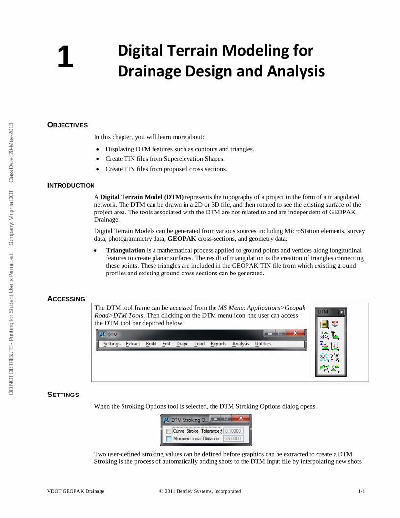
OBJECTIVES In this chapter, you will learn more about:
• Displaying DTM features such as contours and triangles. • Create TIN files from Superelevation Shapes. • Create TIN files from proposed cross sections.
INTRODUCTION A Digital Terrain Model (DTM) represents the topography of a project in the form of a triangulated network. The DTM can be drawn in a 2D or 3D file, and then rotated to see the existing surface of the project area. The tools associated with the DTM are not related to and are independent of GEOPAK Drainage.
Digital Terrain Models can be generated from various sources including MicroStation elements, survey data, photogrammetry data, GEOPAK cross-sections, and geometry data.
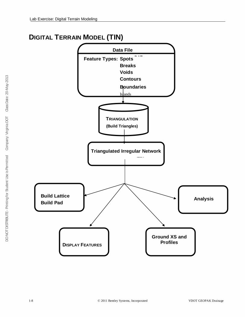
• Triangulation is a mathematical process applied to ground points and vertices along longitudinal features to create planar surfaces. The result of triangulation is the creation of triangles connecting these points. These triangles are included in the GEOPAK TIN file from which existing ground profiles and existing ground cross sections can be generated.
ACCESSING The DTM tool frame can be accessed from the MS Menu: Applications>Geopak Road>DTM Tools. Then clicking on the DTM menu icon, the user can access the DTM tool bar depicted below.
SETTINGS When the Stroking Options tool is selected, the DTM Stroking Options dialog opens.
Two user-defined stroking values can be defined before graphics can be extracted to create a DTM. Stroking is the process of automatically adding shots to the DTM Input file by interpolating new shots
1
DO N
OT
DIST
RIBU
TE -
Prin
ting
for S
tude
nt U
se is
Per
mitt
ed
Co
mpa
ny: V
irgin
ia D
OT
C
lass
Dat
e: 2
0-M
ay-2
013
Extract Graphics
1-2 © 2011 Bentley Systems, Incorporated VDOT GEOPAK Drainage
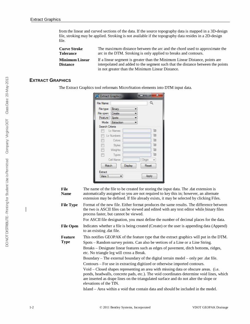
from the linear and curved sections of the data. If the source topography data is mapped in a 3D-design file, stroking may be applied. Stroking is not available if the topography data resides in a 2D-design file.
Curve Stroke Tolerance
The maximum distance between the arc and the chord used to approximate the arc in the DTM. Stroking is only applied to breaks and contours.
Minimum Linear Distance
If a linear segment is greater than the Minimum Linear Distance, points are interpolated and added to the segment such that the distance between the points in not greater than the Minimum Linear Distance.
EXTRACT GRAPHICS The Extract Graphics tool reformats MicroStation elements into DTM input data.
File Name
The name of the file to be created for storing the input data. The .dat extension is automatically assigned so you are not required to key this in; however, an alternate extension may be defined. If file already exists, it may be selected by clicking Files.
File Type Format of the new file. Either format produces the same results. The difference between the two is ASCII files can be viewed and edited with any text editor while binary files process faster, but cannot be viewed. For ASCII file designation, you must define the number of decimal places for the data.
File Open Indicates whether a file is being created (Create) or the user is appending data (Append) to an existing .dat file.
Feature Type
This notifies GEOPAK of the feature type that the extract graphics will put in the DTM. Spots – Random survey points. Can also be vertices of a Line or a Line String. Breaks – Designate linear features such as edges of pavement, ditch bottoms, ridges, etc. No triangle leg will cross a Break. Boundary – The external boundary of the digital terrain model – only per .dat file. Contours – For use in extracting digitized or otherwise imported contours. Void – Closed shapes representing an area with missing data or obscure areas. (i.e. ponds, headwalls, concrete pads, etc.). The void coordinates determine void lines, which are inserted as drape lines on the triangulated surface and do not alter the slope or elevations of the TIN. Island – Area within a void that contain data and should be included in the model.
DO N
OT
DIST
RIBU
TE -
Prin
ting
for S
tude
nt U
se is
Per
mitt
ed
Co
mpa
ny: V
irgin
ia D
OT
C
lass
Dat
e: 2
0-M
ay-2
013
Build Tools
VDOT GEOPAK Drainage © 2011 Bentley Systems, Incorporated 1-3
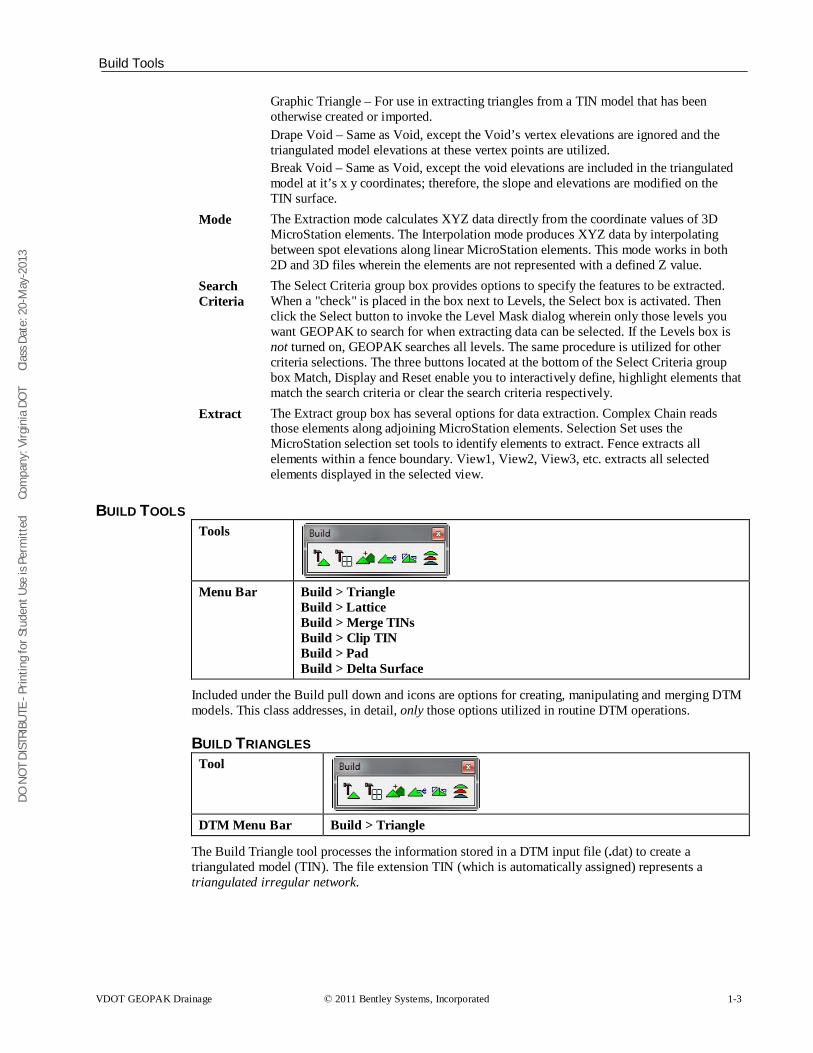
Graphic Triangle – For use in extracting triangles from a TIN model that has been otherwise created or imported. Drape Void – Same as Void, except the Void’s vertex elevations are ignored and the triangulated model elevations at these vertex points are utilized. Break Void – Same as Void, except the void elevations are included in the triangulated model at it’s x y coordinates; therefore, the slope and elevations are modified on the TIN surface.
Mode The Extraction mode calculates XYZ data directly from the coordinate values of 3D MicroStation elements. The Interpolation mode produces XYZ data by interpolating between spot elevations along linear MicroStation elements. This mode works in both 2D and 3D files wherein the elements are not represented with a defined Z value.
Search Criteria
The Select Criteria group box provides options to specify the features to be extracted. When a "check" is placed in the box next to Levels, the Select box is activated. Then click the Select button to invoke the Level Mask dialog wherein only those levels you want GEOPAK to search for when extracting data can be selected. If the Levels box is not turned on, GEOPAK searches all levels. The same procedure is utilized for other criteria selections. The three buttons located at the bottom of the Select Criteria group box Match, Display and Reset enable you to interactively define, highlight elements that match the search criteria or clear the search criteria respectively.
Extract The Extract group box has several options for data extraction. Complex Chain reads those elements along adjoining MicroStation elements. Selection Set uses the MicroStation selection set tools to identify elements to extract. Fence extracts all elements within a fence boundary. View1, View2, View3, etc. extracts all selected elements displayed in the selected view.
BUILD TOOLS Tools
Menu Bar Build > Triangle
Build > Lattice Build > Merge TINs Build > Clip TIN Build > Pad Build > Delta Surface
Included under the Build pull down and icons are options for creating, manipulating and merging DTM models. This class addresses, in detail, only those options utilized in routine DTM operations.
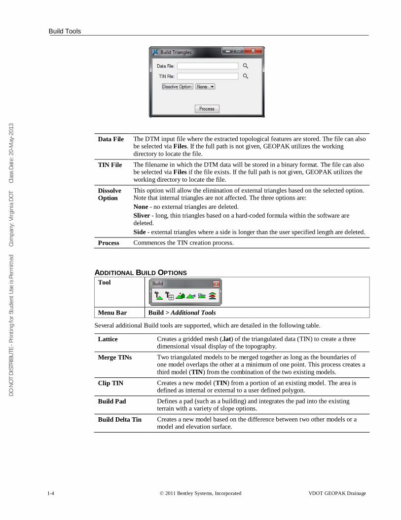
BUILD TRIANGLES Tool
DTM Menu Bar Build > Triangle
The Build Triangle tool processes the information stored in a DTM input file (.dat) to create a triangulated model (TIN). The file extension TIN (which is automatically assigned) represents a triangulated irregular network.
DO N
OT
DIST
RIBU
TE -
Prin
ting
for S
tude
nt U
se is
Per
mitt
ed
Co
mpa
ny: V
irgin
ia D
OT
C
lass
Dat
e: 2
0-M
ay-2
013
Build Tools
1-4 © 2011 Bentley Systems, Incorporated VDOT GEOPAK Drainage
Data File The DTM input file where the extracted topological features are stored. The file can also be selected via Files. If the full path is not given, GEOPAK utilizes the working directory to locate the file.
TIN File The filename in which the DTM data will be stored in a binary format. The file can also be selected via Files if the file exists. If the full path is not given, GEOPAK utilizes the working directory to locate the file.
Dissolve Option
This option will allow the elimination of external triangles based on the selected option. Note that internal triangles are not affected. The three options are: None - no external triangles are deleted. Sliver - long, thin triangles based on a hard-coded formula within the software are deleted. Side - external triangles where a side is longer than the user specified length are deleted.
Process Commences the TIN creation process.
ADDITIONAL BUILD OPTIONS Tool
Menu Bar Build > Additional Tools
Several additional Build tools are supported, which are detailed in the following table.
Lattice Creates a gridded mesh (.lat) of the triangulated data (TIN) to create a three dimensional visual display of the topography.
Merge TINs Two triangulated models to be merged together as long as the boundaries of one model overlaps the other at a minimum of one point. This process creates a third model (TIN) from the combination of the two existing models.
Clip TIN Creates a new model (TIN) from a portion of an existing model. The area is defined as internal or external to a user defined polygon.
Build Pad Defines a pad (such as a building) and integrates the pad into the existing terrain with a variety of slope options.
Build Delta Tin Creates a new model based on the difference between two other models or a model and elevation surface.
DO N
OT
DIST
RIBU
TE -
Prin
ting
for S
tude
nt U
se is
Per
mitt
ed
Co
mpa
ny: V
irgin
ia D
OT
C
lass
Dat
e: 2
0-M
ay-2
013
Reports
VDOT GEOPAK Drainage © 2011 Bentley Systems, Incorporated 1-5
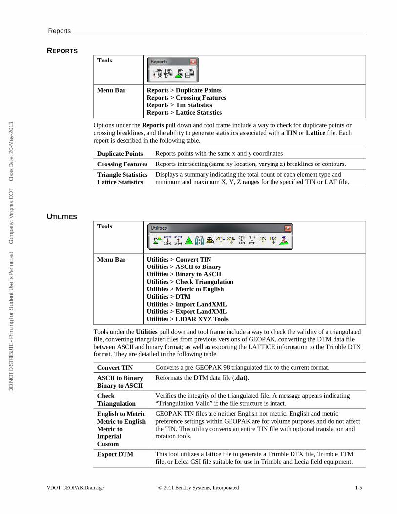
REPORTS Tools
Menu Bar Reports > Duplicate Points
Reports > Crossing Features Reports > Tin Statistics Reports > Lattice Statistics
Options under the Reports pull down and tool frame include a way to check for duplicate points or crossing breaklines, and the ability to generate statistics associated with a TIN or Lattice file. Each report is described in the following table.
Duplicate Points Reports points with the same x and y coordinates
Crossing Features Reports intersecting (same xy location, varying z) breaklines or contours.
Triangle Statistics Lattice Statistics
Displays a summary indicating the total count of each element type and minimum and maximum X, Y, Z ranges for the specified TIN or LAT file.
UTILITIES Tools
Menu Bar Utilities > Convert TIN Utilities > ASCII to Binary Utilities > Binary to ASCII Utilities > Check Triangulation Utilities > Metric to English Utilities > DTM Utilities > Import LandXML Utilities > Export LandXML Utilities > LIDAR XYZ Tools
Tools under the Utilities pull down and tool frame include a way to check the validity of a triangulated file, converting triangulated files from previous versions of GEOPAK, converting the DTM data file between ASCII and binary format; as well as exporting the LATTICE information to the Trimble DTX format. They are detailed in the following table.
Convert TIN Converts a pre-GEOPAK 98 triangulated file to the current format.
ASCII to Binary Binary to ASCII
Reformats the DTM data file (.dat).
Check Triangulation
Verifies the integrity of the triangulated file. A message appears indicating “Triangulation Valid” if the file structure is intact.
English to Metric Metric to English Metric to Imperial Custom
GEOPAK TIN files are neither English nor metric. English and metric preference settings within GEOPAK are for volume purposes and do not affect the TIN. This utility converts an entire TIN file with optional translation and rotation tools.
Export DTM This tool utilizes a lattice file to generate a Trimble DTX file, Trimble TTM file, or Leica GSI file suitable for use in Trimble and Lecia field equipment.
DO N
OT
DIST
RIBU
TE -
Prin
ting
for S
tude
nt U
se is
Per
mitt
ed
Co
mpa
ny: V
irgin
ia D
OT
C
lass
Dat
e: 2
0-M
ay-2
013
1-6 © 2011 Bentley Systems, Incorporated VDOT GEOPAK Drainage
Import LandXML This tool is utilized to create a DAT file from a LandXML file.
Export LandXML This tool is utilized to create a LandXML file from a TIN file.
LIDAR XYZ Tools
This tool set is used to process, filter, clip, compare, report, and display LIDAR data.
LOAD DTM FEATURES
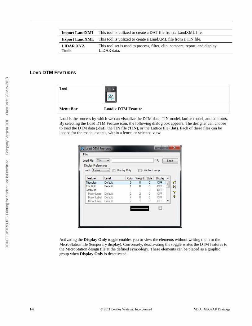
Tool
Menu Bar Load > DTM Feature
Load is the process by which we can visualize the DTM data, TIN model, lattice model, and contours. By selecting the Load DTM Feature icon, the following dialog box appears. The designer can choose to load the DTM data (.dat), the TIN file (TIN), or the Lattice file (.lat). Each of these files can be loaded for the model extents, within a fence, or selected view.
Activating the Display Only toggle enables you to view the elements without writing them to the MicroStation file (temporary display). Conversely, deactivating the toggle writes the DTM features to the MicroStation design file at the defined symbology. These elements can be placed as a graphic group when Display Only is deactivated.
DO N
OT
DIST
RIBU
TE -
Prin
ting
for S
tude
nt U
se is
Per
mitt
ed
Co
mpa
ny: V
irgin
ia D
OT
C
lass
Dat
e: 2
0-M
ay-2
013
Edit Tools
VDOT GEOPAK Drainage © 2011 Bentley Systems, Incorporated 1-7
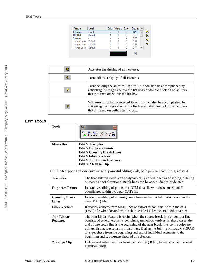
Activates the display of all Features.
Turns off the Display of all Features.
Turns on only the selected Feature. This can also be accomplished by activating the toggle (below the list box) or double-clicking on an item that is turned off within the list box.
Will turn off only the selected item. This can also be accomplished by activating the toggle (below the list box) or double-clicking on an item that is turned on within the list box.
EDIT TOOLS Tools
Menu Bar Edit > Triangles Edit > Duplicate Points Edit > Crossing Break Lines Edit > Filter Vertices Edit > Join Linear Features Edit > Z Range Clip
GEOPAK supports an extensive range of powerful editing tools, both pre- and post TIN generating.
Triangles The triangulated model can be dynamically edited in terms of adding, deleting or moving spot elevations. Break lines can be added, draped or deleted.
Duplicate Points Interactive editing of points in a DTM data file with the same X and Y coordinates within the data (DAT) file.
Crossing Break Lines
Interactive editing of crossing break lines and extracted contours within the data (DAT) file.
Filter Vertices Removes vertices from break lines or extracted contours within the data (DAT) file when located within the specified Tolerance of another vertex.
Join Linear Features
The Join Linear Feature is useful when the source break line or contour line consists of several elements containing numerous vertices. In these cases, the end of one break line is the beginning of the next break line, so the software utilizes this as two separate break lines. During the Joining process, GEOPAK changes these from the beginning and end of individual elements to the beginning and subsequent shots of one element.
Z Range Clip Deletes individual vertices from the data file (.DAT) based on a user defined elevation range.
DO N
OT
DIST
RIBU
TE -
Prin
ting
for S
tude
nt U
se is
Per
mitt
ed
Co
mpa
ny: V
irgin
ia D
OT
C
lass
Dat
e: 2
0-M
ay-2
013
Lab Exercise: Digital Terrain Modeling
1-8 © 2011 Bentley Systems, Incorporated VDOT GEOPAK Drainage
DIGITAL TERRAIN MODEL (TIN)
Data File DAT Feature Types: Spots
Breaks Voids Contours
Boundaries Islands
TRIANGULATION (Build Triangles)
Triangulated Irregular Network TIN
Build Lattice Build Pad
DISPLAY FEATURES Ground XS and
Profiles
Analysis
DO N
OT
DIST
RIBU
TE -
Prin
ting
for S
tude
nt U
se is
Per
mitt
ed
Co
mpa
ny: V
irgin
ia D
OT
C
lass
Dat
e: 2
0-M
ay-2
013
Lab Exercise: Digital Terrain Modeling
VDOT GEOPAK Drainage © 2011 Bentley Systems, Incorporated 1-9
LAB EXERCISE: DIGITAL TERRAIN MODELING The purpose of this exercise is to review the triangles of a tin file and to create contours from it.
> Accessing DTM Tools
1. Execute c:\data\geo\vdot\drain1\LAB01_V8_SELECTseries.exe. 2. Open the MicroStation file, c:\data\geo\vdot\drain1\h17682.dgn. 3. Access the GEOPAK DTM Tools frame. (Applications > GEOPAK >ROAD> DTM Tools)
> Load DTM Features
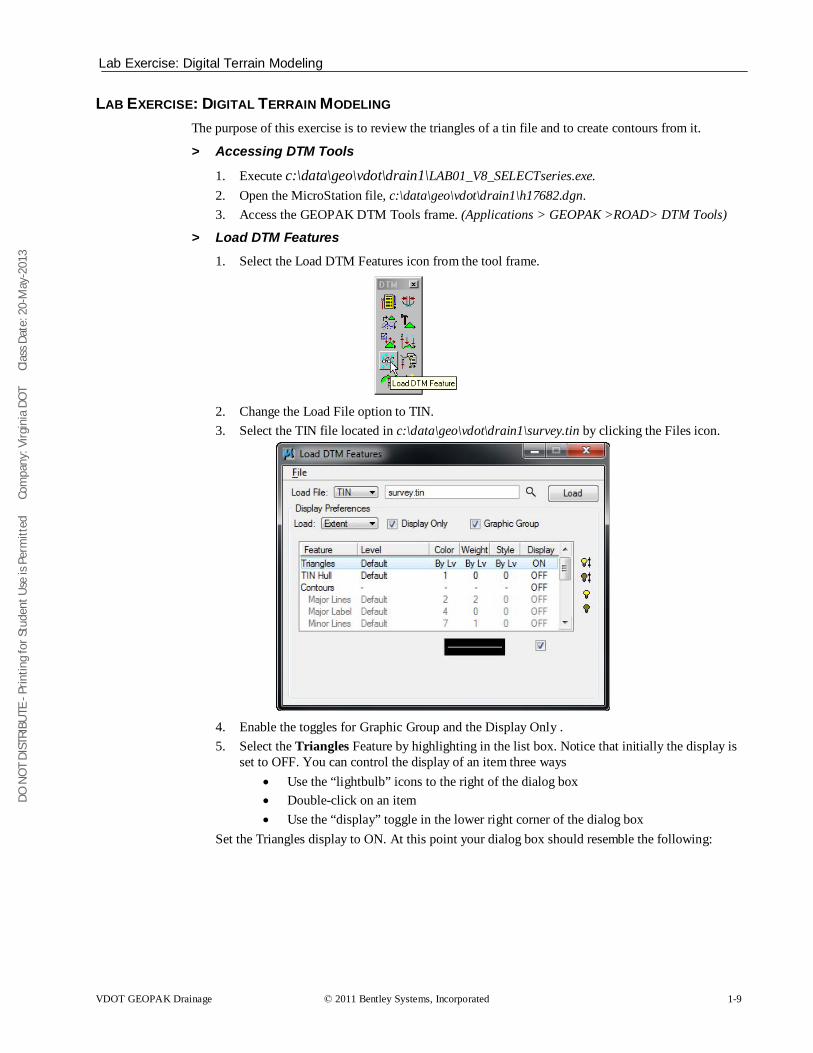
1. Select the Load DTM Features icon from the tool frame.
2. Change the Load File option to TIN. 3. Select the TIN file located in c:\data\geo\vdot\drain1\survey.tin by clicking the Files icon.
4. Enable the toggles for Graphic Group and the Display Only . 5. Select the Triangles Feature by highlighting in the list box. Notice that initially the display is
set to OFF. You can control the display of an item three ways • Use the “lightbulb” icons to the right of the dialog box • Double-click on an item • Use the “display” toggle in the lower right corner of the dialog box
Set the Triangles display to ON. At this point your dialog box should resemble the following:
DO N
OT
DIST
RIBU
TE -
Prin
ting
for S
tude
nt U
se is
Per
mitt
ed
Co
mpa
ny: V
irgin
ia D
OT
C
lass
Dat
e: 2
0-M
ay-2
013
Lab Exercise: Digital Terrain Modeling
1-10 © 2011 Bentley Systems, Incorporated VDOT GEOPAK Drainage
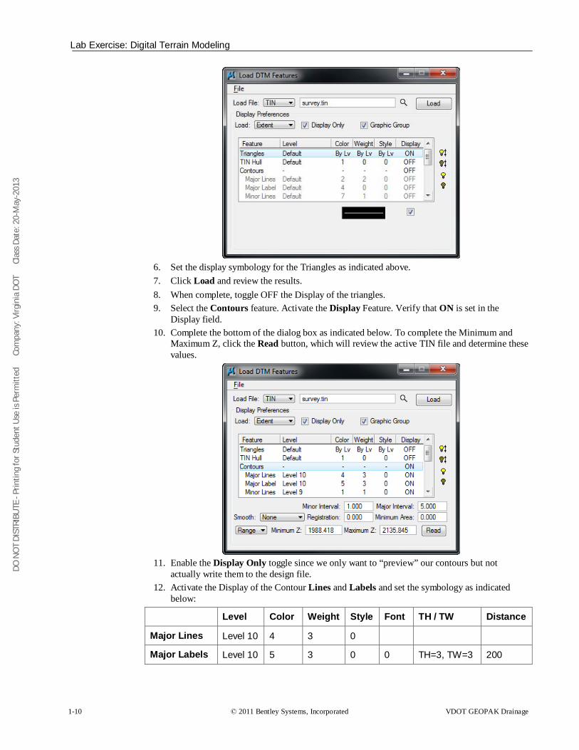
6. Set the display symbology for the Triangles as indicated above. 7. Click Load and review the results. 8. When complete, toggle OFF the Display of the triangles. 9. Select the Contours feature. Activate the Display Feature. Verify that ON is set in the
Display field. 10. Complete the bottom of the dialog box as indicated below. To complete the Minimum and
Maximum Z, click the Read button, which will review the active TIN file and determine these values.
11. Enable the Display Only toggle since we only want to “preview” our contours but not
actually write them to the design file. 12. Activate the Display of the Contour Lines and Labels and set the symbology as indicated
below:
Level Color Weight Style Font TH / TW Distance
Major Lines Level 10 4 3 0
Major Labels Level 10 5 3 0 0 TH=3, TW=3 200

DO N
OT
DIST
RIBU
TE -
Prin
ting
for S
tude
nt U
se is
Per
mitt
ed
Co
mpa
ny: V
irgin
ia D
OT
C
lass
Dat
e: 2
0-M
ay-2
013
Proposed Cross Sections to DTM
VDOT GEOPAK Drainage © 2011 Bentley Systems, Incorporated 1-11
Minor Lines Level 9 1 1 0
13. Click the Load button to initiate the process. 14. Close the Load DTM Features dialog box.
PROPOSED CROSS SECTIONS TO DTM The DTM Prop 3D tool locates specified proposed cross section elements and existing ground, and generates an x, y, z file of vertices for break lines suitable for use with GEOPAK's Digital Terrain Modeling. Each cross section generates one break line. In the hierarchy, the path follows (from left to right) existing ground until a proposed finish element is intersected. The proposed path is followed until it ties back to an existing ground element.
Job Job which contains the cross section chain.
Chain Chain utilized to generate the existing ground cross sections or the name on the XSCELL
Current Station Defaults to the lowest stationed cross section in the file. During processing, the current cross section being reported is displayed
Begin Station / End Station GEOPAK determines the beginning and ending cross section station within the MicroStation file and they are noted below the chain and placed in the key-in areas. If these defaults are utilized, the report is generated for the entire set of cross sections. However, if a report for a smaller range is required, the user may simply key in the required beginning and/or ending station.
Search Criteria: Existing Ground Line/Proposed Finish Grade
Refers to the Microstation symbology used to draw the existing ground line and any Microstation element that makes up the upper layer of the proposed cross section.
Pause on Each XS When the toggle is activated, the first section is processed and stops. Each click of Apply processed another section.
DO N
OT
DIST
RIBU
TE -
Prin
ting
for S
tude
nt U
se is
Per
mitt
ed
Co
mpa
ny: V
irgin
ia D
OT
C
lass
Dat
e: 2
0-M
ay-2
013
Lab Exercise: Proposed Cross Sections to DTM
1-12 © 2011 Bentley Systems, Incorporated VDOT GEOPAK Drainage
ASCII File Specify the name of the ASCII file to be generated. The designer has the option of keying in the file name, or clicking Files, invoking the Files dialog, wherein the designer may select the desired file. The file is placed in the current directory, unless a full path is specified. If the specified file name already exists, the file is overwritten with no warning message given.
Apply Commences processing.
LAB EXERCISE: PROPOSED CROSS SECTIONS TO DTM The purpose of this exercise is to create a proposed dtm from the roadway cross sections developed by the roadway designers. The newly created dtm will include the existing and proposed elements of the roadway merged together.
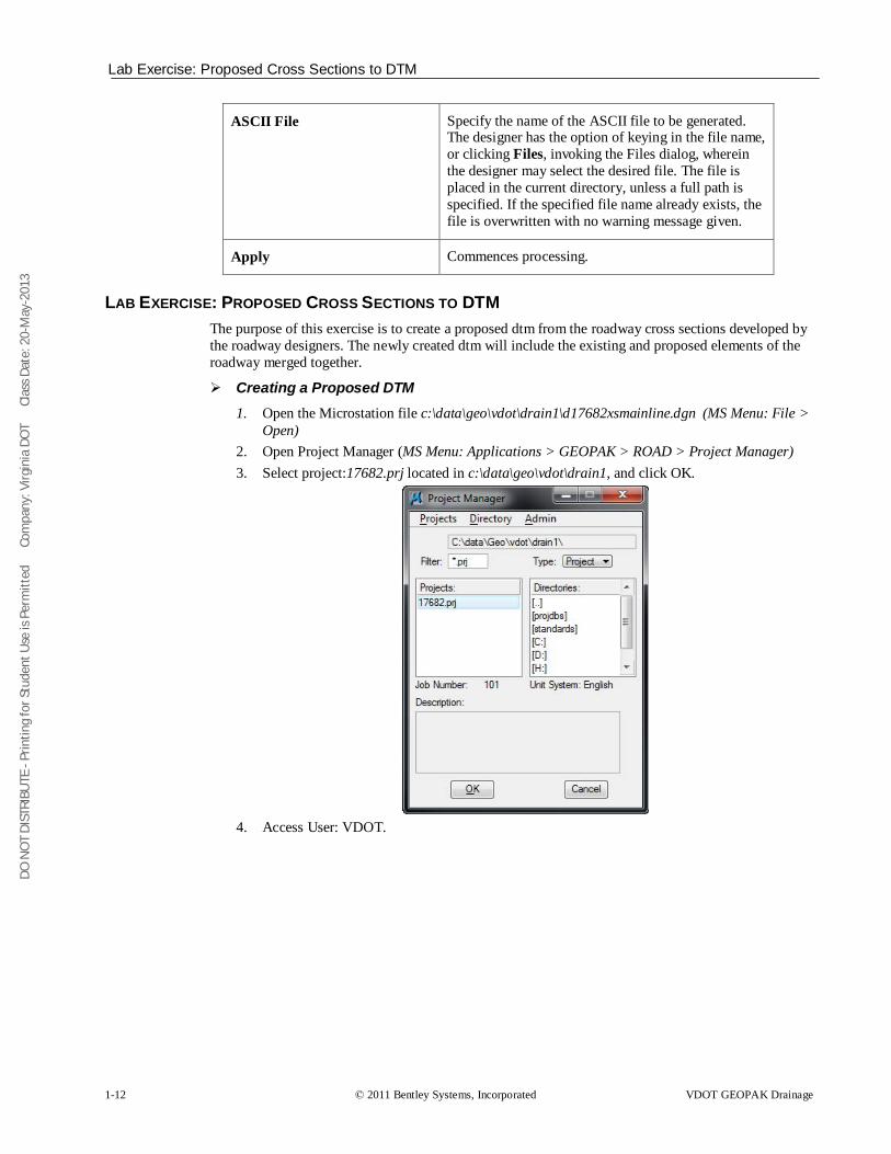
Creating a Proposed DTM 1. Open the Microstation file c:\data\geo\vdot\drain1\d17682xsmainline.dgn (MS Menu: File >
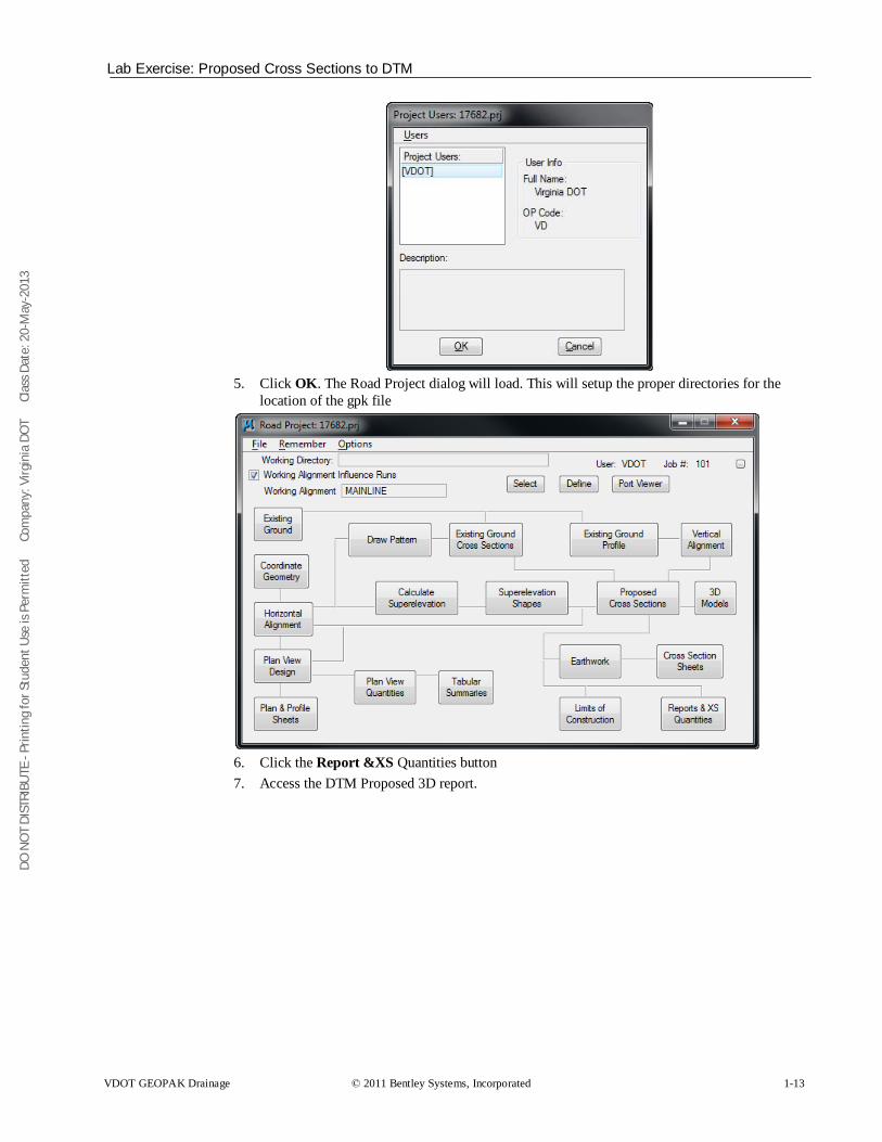
Open) 2. Open Project Manager (MS Menu: Applications > GEOPAK > ROAD > Project Manager) 3. Select project:17682.prj located in c:\data\geo\vdot\drain1, and click OK.
4. Access User: VDOT.
DO N
OT
DIST
RIBU
TE -
Prin
ting
for S
tude
nt U
se is
Per
mitt
ed
Co
mpa
ny: V
irgin
ia D
OT
C
lass
Dat
e: 2
0-M
ay-2
013
Lab Exercise: Proposed Cross Sections to DTM
VDOT GEOPAK Drainage © 2011 Bentley Systems, Incorporated 1-13
5. Click OK. The Road Project dialog will load. This will setup the proper directories for the
location of the gpk file
6. Click the Report &XS Quantities button 7. Access the DTM Proposed 3D report.
DO N
OT
DIST
RIBU
TE -
Prin
ting
for S
tude
nt U
se is
Per
mitt
ed
Co
mpa
ny: V
irgin
ia D
OT
C
lass
Dat
e: 2
0-M
ay-2
013
Lab Exercise: Proposed Cross Sections to DTM
1-14 © 2011 Bentley Systems, Incorporated VDOT GEOPAK Drainage
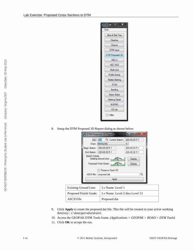
8. Setup the DTM Proposed 3D Report dialog as shown below.
Existing Ground Line: Lv Name: Level 1
Proposed Finish Grade: Lv Name: Level 2 thru Level 13
ASCII File Proposed.dat
9. Click Apply to create the proposed.dat file. This file will be created in your active working
directory : c:\data\geo\vdot\drain1. 10. Access the GEOPAK DTM Tools frame. (Applications > GEOPAK > ROAD > DTM Tools) 11. Click OK to accept the run.
DO N
OT
DIST
RIBU
TE -
Prin
ting
for S
tude
nt U
se is
Per
mitt
ed
Co
mpa
ny: V
irgin
ia D
OT
C
lass
Dat
e: 2
0-M
ay-2
013
Lab Exercise: Proposed Cross Sections to DTM
VDOT GEOPAK Drainage © 2011 Bentley Systems, Incorporated 1-15
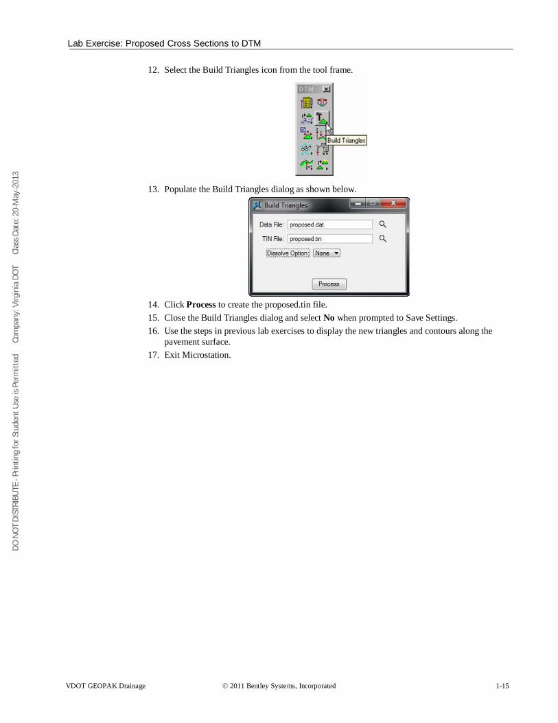
12. Select the Build Triangles icon from the tool frame.
13. Populate the Build Triangles dialog as shown below.
14. Click Process to create the proposed.tin file. 15. Close the Build Triangles dialog and select No when prompted to Save Settings. 16. Use the steps in previous lab exercises to display the new triangles and contours along the
pavement surface. 17. Exit Microstation.
DO N
OT
DIST
RIBU
TE -
Prin
ting
for S
tude
nt U
se is
Per
mitt
ed
Co
mpa
ny: V
irgin
ia D
OT
C
lass
Dat
e: 2
0-M
ay-2
013
Lab Exercise: Proposed Cross Sections to DTM
1-16 © 2011 Bentley Systems, Incorporated VDOT GEOPAK Drainage

DO N
OT
DIST
RIBU
TE -
Prin
ting
for S
tude
nt U
se is
Per
mitt
ed
Co
mpa
ny: V
irgin
ia D
OT
C
lass
Dat
e: 2
0-M
ay-2
013
VDOT GEOPAK Drainage © 2011 Bentley Systems, Incorporated 2-1
Drainage Analysis
OBJECTIVES Learn how to use different Geopak DTM, shapes and VBA tools for the analysis and creation of drainage areas in a project.
INTRODUCTION A Digital Terrain Model (DTM) represents the topography of a project in the form of a triangulated network. The DTM can be drawn in a 2D or 3D file, and then rotated to see the existing surface of the project area. The tools associated with the DTM are not related to and are independent of GEOPAK Drainage.
ACCESSING The DTM tool frame can be accessed from the MS Menu: Applications>Geopak Road>DTM Tools. Then clicking on the DTM menu icon, the user can access the DTM tool bar depicted below.
ANALYSIS TOOLS Tools
Menu Bar Analysis > Height Analysis > Profile Analysis > Volumes Analysis > Elevation Differences Analysis > Slope Area Analysis > Themes Analysis > Drainage Tools Analysis > Visibility Analysis > Trace Slope Path Analysis > DTM Camera Analysis > Trench Volumes
The Analysis tools allow you to visually analyze the digital terrain model utilizing numerous tools as a profile analysis, thematic analysis, drainage flow patterns, and visual portions on the model from any given location.
2
DO N
OT
DIST
RIBU
TE -
Prin
ting
for S
tude
nt U
se is
Per
mitt
ed
Co
mpa
ny: V
irgin
ia D
OT
C
lass
Dat
e: 2
0-M
ay-2
013
Analysis Tools: Drainage
2-2 © 2011 Bentley Systems, Incorporated VDOT GEOPAK Drainage
Height To determine the height and other associated data dynamically based on user-defined data points within the model.
Profile View a profile based on a user defined MicroStation element.
Volumes To compute the volume between two TIN models, the volume between a TIN model and a plane, or the cut and fill totals between two TIN models while applying a shrinkage/swell factors.
Elevation Differences Will display the elevation difference or the amount of cut and fill between two TIN models, or a TIN model and a plane of constant elevation.
Slope Area The Slope Area tool displays the horizontal area and actual slope area (area following the terrain of the Model).
Themes Displays the digital terrain model based on different user definable themes such as elevation ranges, slope percentage, slope degree, or aspect.
Drainage Displays and analyzes drainage patterns within a TIN model. Tools include delineating watersheds, drawing flow arrows, determining upstream and downstream traces, finding high and low points, and ridge and sump lines.
Visibility Based on a user-defined point of origin, GEOPAK visually displays which triangles can and cannot be seen, or what is visible between two points.
Trace Slope Path Traces a path along a TIN file using a user specified slope and method.
DTM Camera Allows a 3d visualization camera for the DTM
Trench Volumes Compute the excavation volume needed along the drainage pipes.
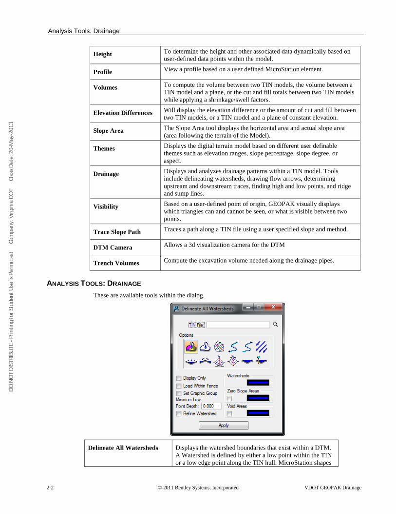
ANALYSIS TOOLS: DRAINAGE These are available tools within the dialog.
Delineate All Watersheds Displays the watershed boundaries that exist within a DTM. A Watershed is defined by either a low point within the TIN or a low edge point along the TIN hull. MicroStation shapes
DO N
OT
DIST
RIBU
TE -
Prin
ting
for S
tude
nt U
se is
Per
mitt
ed
Co
mpa
ny: V
irgin
ia D
OT
C
lass
Dat
e: 2
0-M
ay-2
013
Analysis Tools: Drainage
VDOT GEOPAK Drainage © 2011 Bentley Systems, Incorporated 2-3
may be created for each watershed contained in the TIN. Two important options to consider are:
• Minimum Low Point Depth: A DTM has many low points in which drainage areas could be delineated, but many of depth are small dips in the TIN file in which water will keep flowing. GEOPAK determines each low point, then determines if water placed at the specified depth overflows these dips in the DTM and flows into adjacent triangles. If it does not flow into adjacent triangles, it is identified as a low point and the drainage area is delimited. The designer must use the appropriate criteria to set this value.
• Refine Watershed: this option processes the entire TIN evaluating ridges, sumps, and low points and determines more precise flow boundaries within the triangles. It does not retriangulate, more specifically it insert lines within the TIN that actually represent flow divides.
Delineate Watershed The Delineate Watershed tool further delineates watersheds at any location within the TIN. A data point representing the pour point of the watershed is indicated and the contributing watershed area is computed and delineated.
Drainage Patterns Evaluates the flow paths contained in a region of the TIN, Model or Object. This tool performs a downstream trace from the centroid of each triangle contained in the region specified.
Downstream Trace Trace tool delineates the flow path downstream from a given point in the TIN. The indicated path follows the steepest descent from the point through the TIN terminating at a low point or the edge of the TIN.
Upstream Trace Delineates the flow path upstream from a given point in the TIN. The indicated path follows the steepest ascent from the point through the TIN terminating at a high point or the edge of the TIN.
Flow Arrows Indicates the direction of flow within the triangles for a given region of the TIN.
Delineate Low Points Locates all low points within a region of a TIN. A flow arrow is placed and the text "LP" is placed at the triangle vertex. Text placement utilizes the current MicroStation text parameters.
Delineate High Points Locates all the high points within a region of a TIN. A flow arrow is placed and the text "HP" is placed at the triangle vertex. Text placement utilizes the current MicroStation text parameters.
DO N
OT
DIST
RIBU
TE -
Prin
ting
for S
tude
nt U
se is
Per
mitt
ed
Co
mpa
ny: V
irgin
ia D
OT
C
lass
Dat
e: 2
0-M
ay-2
013
Analysis Tools: Drainage
2-4 © 2011 Bentley Systems, Incorporated VDOT GEOPAK Drainage
Delineate Ridge Lines Indicates the ridge lines within a region of a TIN. A ridge line is defined as a triangle edge where the flow on each side of the edge is away from the edge.
Delineate Sump Lines Indicates the sump lines within a region of a TIN. A sump line is defined as a triangle edge where the flow on each side of the edge is towards the edge and is found in areas of concentrated flows such as streams and ditches.
Surface Ponds Delineates the area(s) of ponded water within the specified TIN.
Pond Analysis Traces a point downstream to a low point and fills it giving the volume, maximum depth, and maximum elevation. In addition, the pond delineation is graphically displayed.
DO N
OT
DIST
RIBU
TE -
Prin
ting
for S
tude
nt U
se is
Per
mitt
ed
Co
mpa
ny: V
irgin
ia D
OT
C
lass
Dat
e: 2
0-M
ay-2
013
Lab Exercise: Analysis of the Proposed DTM
VDOT GEOPAK Drainage © 2011 Bentley Systems, Incorporated 2-5
LAB EXERCISE: ANALYSIS OF THE PROPOSED DTM Accessing DTM Tools
1. Execute c:\data\geo\VDOT\drain1\LAB02_V8_SELECTseries.exe. 2. Open the MicroStation file, c:\data\geo\VDOT\drain1\h17682da.dgn. 3. Access the GEOPAK DTM Tools frame. (Applications > GEOPAK > ROAD > DTM Tools)
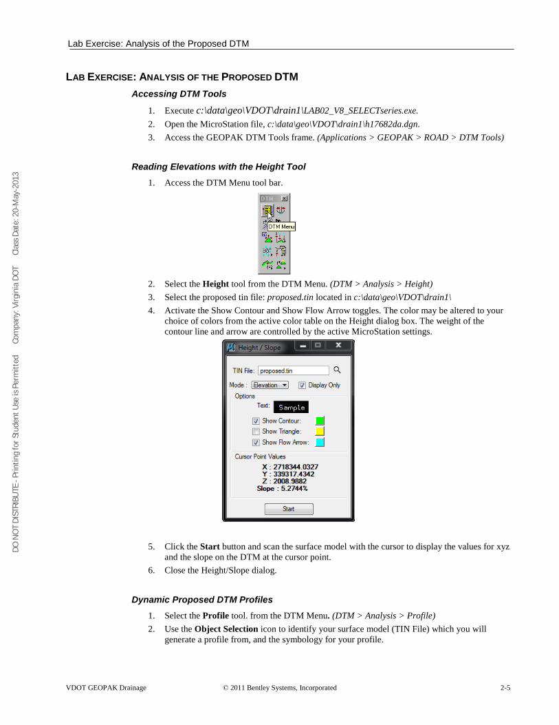
Reading Elevations with the Height Tool 1. Access the DTM Menu tool bar.
2. Select the Height tool from the DTM Menu. (DTM > Analysis > Height) 3. Select the proposed tin file: proposed.tin located in c:\data\geo\VDOT\drain1\ 4. Activate the Show Contour and Show Flow Arrow toggles. The color may be altered to your
choice of colors from the active color table on the Height dialog box. The weight of the contour line and arrow are controlled by the active MicroStation settings.
5. Click the Start button and scan the surface model with the cursor to display the values for xyz and the slope on the DTM at the cursor point.
6. Close the Height/Slope dialog.
Dynamic Proposed DTM Profiles 1. Select the Profile tool. from the DTM Menu. (DTM > Analysis > Profile) 2. Use the Object Selection icon to identify your surface model (TIN File) which you will
generate a profile from, and the symbology for your profile.
DO N
OT
DIST
RIBU
TE -
Prin
ting
for S
tude
nt U
se is
Per
mitt
ed
Co
mpa
ny: V
irgin
ia D
OT
C
lass
Dat
e: 2
0-M
ay-2
013
Lab Exercise: Analysis of the Proposed DTM
2-6 © 2011 Bentley Systems, Incorporated VDOT GEOPAK Drainage
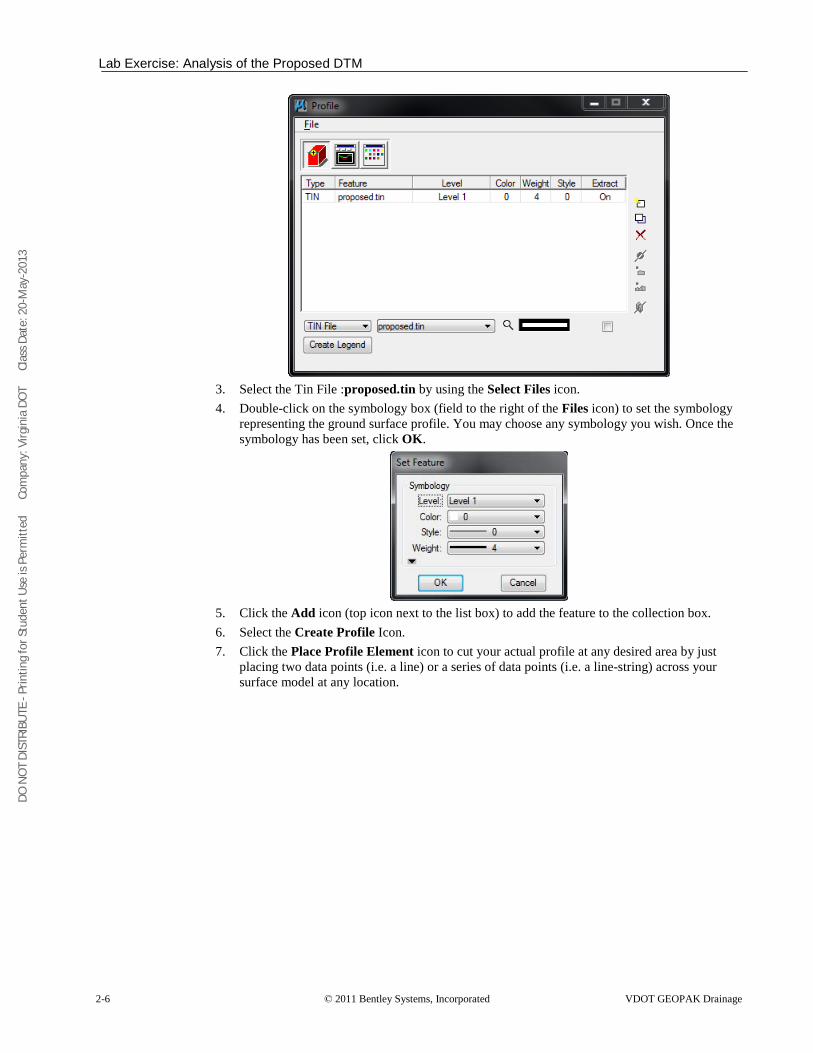
3. Select the Tin File :proposed.tin by using the Select Files icon. 4. Double-click on the symbology box (field to the right of the Files icon) to set the symbology
representing the ground surface profile. You may choose any symbology you wish. Once the symbology has been set, click OK.
5. Click the Add icon (top icon next to the list box) to add the feature to the collection box. 6. Select the Create Profile Icon. 7. Click the Place Profile Element icon to cut your actual profile at any desired area by just
placing two data points (i.e. a line) or a series of data points (i.e. a line-string) across your surface model at any location.
DO N
OT
DIST
RIBU
TE -
Prin
ting
for S
tude
nt U
se is
Per
mitt
ed
Co
mpa
ny: V
irgin
ia D
OT
C
lass
Dat
e: 2
0-M
ay-2
013
Lab Exercise: Analysis of the Proposed DTM
VDOT GEOPAK Drainage © 2011 Bentley Systems, Incorporated 2-7
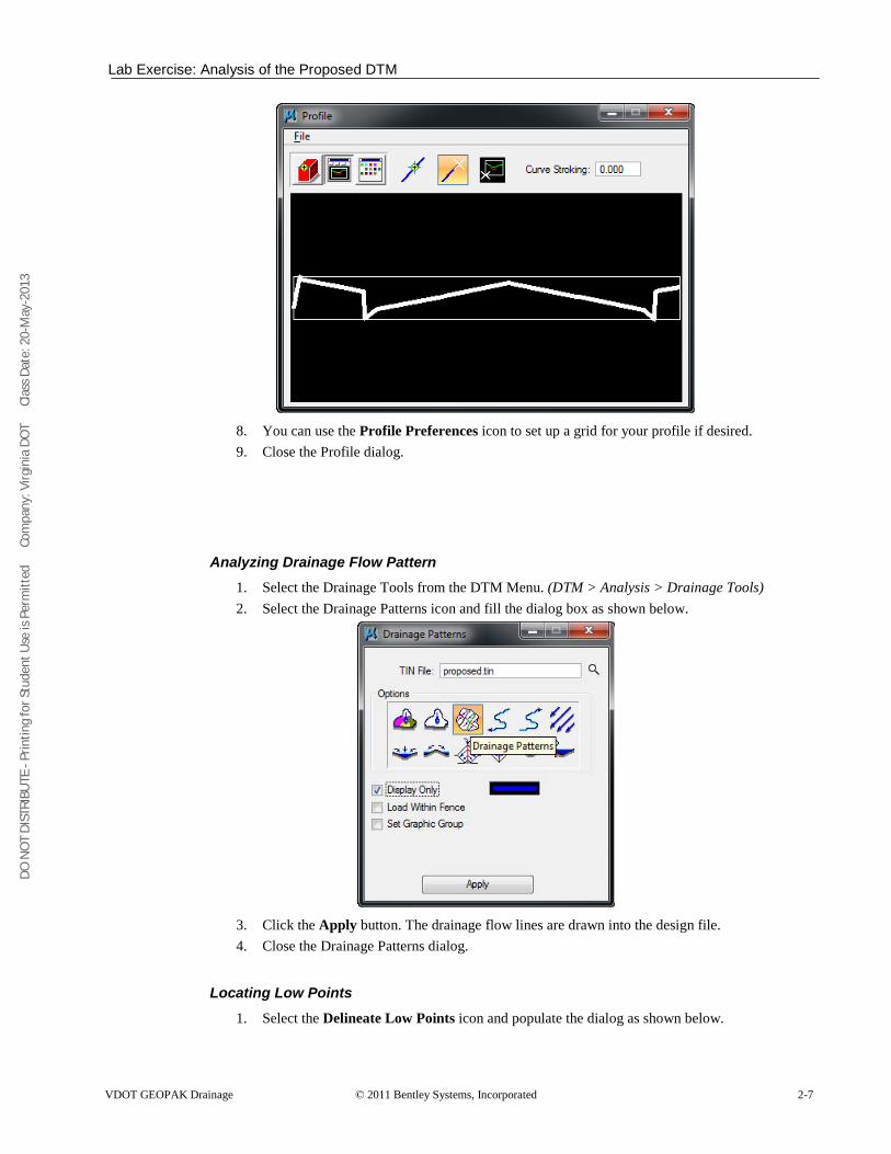
8. You can use the Profile Preferences icon to set up a grid for your profile if desired. 9. Close the Profile dialog.
Analyzing Drainage Flow Pattern 1. Select the Drainage Tools from the DTM Menu. (DTM > Analysis > Drainage Tools) 2. Select the Drainage Patterns icon and fill the dialog box as shown below.
3. Click the Apply button. The drainage flow lines are drawn into the design file. 4. Close the Drainage Patterns dialog.
Locating Low Points 1. Select the Delineate Low Points icon and populate the dialog as shown below.

DO N
OT
DIST
RIBU
TE -
Prin
ting
for S
tude
nt U
se is
Per
mitt
ed
Co
mpa
ny: V
irgin
ia D
OT
C
lass
Dat
e: 2
0-M
ay-2
013
Lab Exercise: Analysis of the Proposed DTM
2-8 © 2011 Bentley Systems, Incorporated VDOT GEOPAK Drainage
2. Click Apply to review the low points location in the Microstation file. 3. Close the Delineate Low Points dialog.
Delineating Drainage Areas 1. Select the Delineate All Watersheds icon and populate the dialog as shown below.
2. Click Apply and review the tentative watersheds for the pavement drainage. 3. Close the Delineate All Watersheds dialog when done.
Note This process will define all the “mathematically” possible drainage watersheds. The designer will need to define the final drainage areas for the project.
Scouting for Pond Locations 1. Select the Surface Ponds icon.
DO N
OT
DIST
RIBU
TE -
Prin
ting
for S
tude
nt U
se is
Per
mitt
ed
Co
mpa
ny: V
irgin
ia D
OT
C
lass
Dat
e: 2
0-M
ay-2
013
Lab Exercise: Analysis of the Proposed DTM
VDOT GEOPAK Drainage © 2011 Bentley Systems, Incorporated 2-9
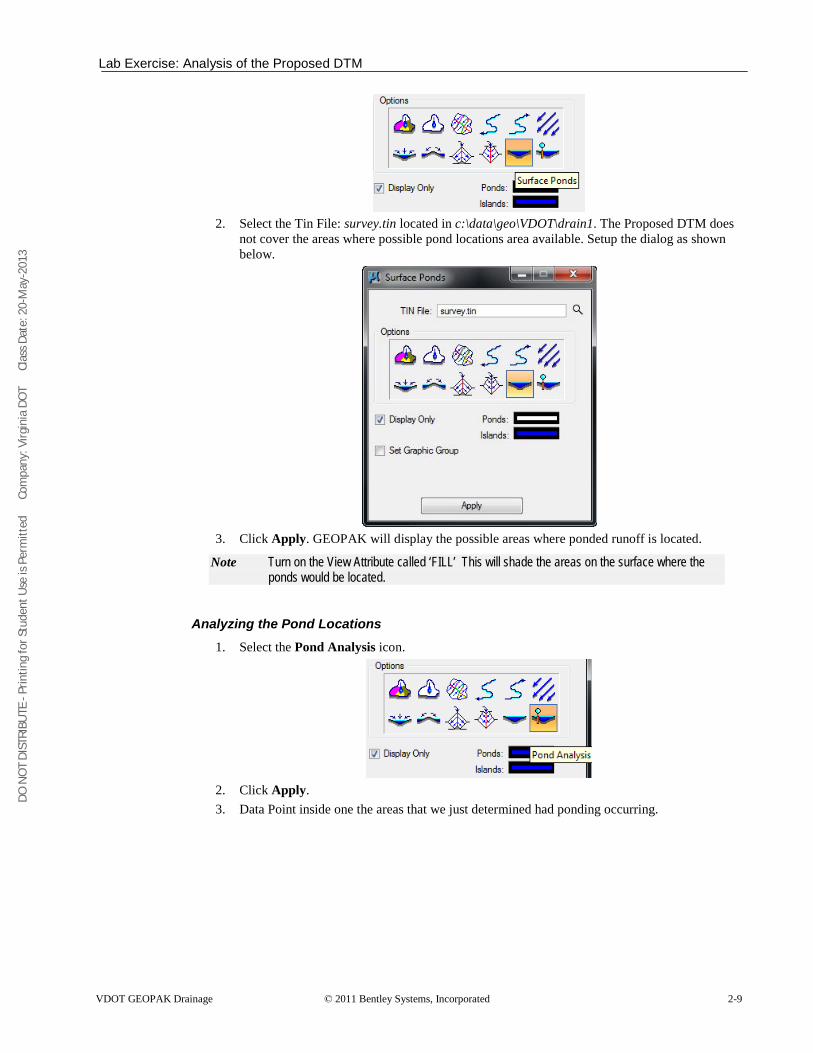
2. Select the Tin File: survey.tin located in c:\data\geo\VDOT\drain1. The Proposed DTM does
not cover the areas where possible pond locations area available. Setup the dialog as shown below.
3. Click Apply. GEOPAK will display the possible areas where ponded runoff is located.
Note Turn on the View Attribute called ‘FILL’ This will shade the areas on the surface where the ponds would be located.
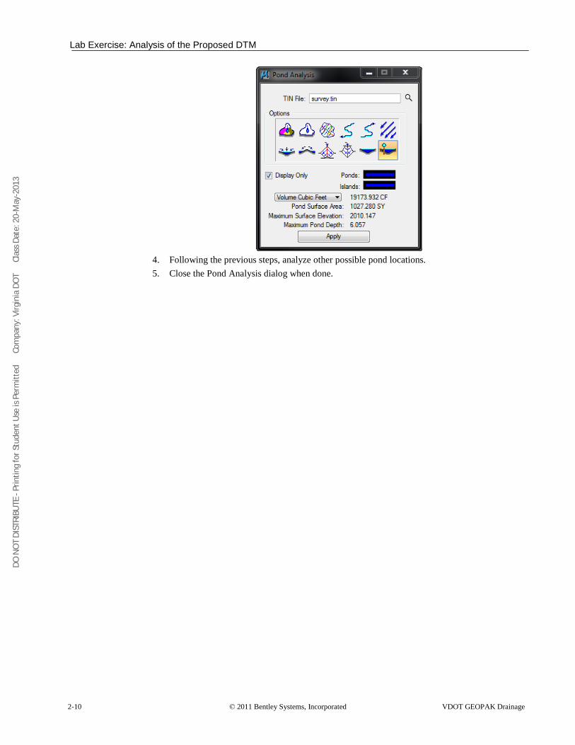
Analyzing the Pond Locations 1. Select the Pond Analysis icon.
2. Click Apply. 3. Data Point inside one the areas that we just determined had ponding occurring.
DO N
OT
DIST
RIBU
TE -
Prin
ting
for S
tude
nt U
se is
Per
mitt
ed
Co
mpa
ny: V
irgin
ia D
OT
C
lass
Dat
e: 2
0-M
ay-2
013
Lab Exercise: Analysis of the Proposed DTM
2-10 © 2011 Bentley Systems, Incorporated VDOT GEOPAK Drainage
4. Following the previous steps, analyze other possible pond locations. 5. Close the Pond Analysis dialog when done.
DO N
OT
DIST
RIBU
TE -
Prin
ting
for S
tude
nt U
se is
Per
mitt
ed
Co
mpa
ny: V
irgin
ia D
OT
C
lass
Dat
e: 2
0-M
ay-2
013
Lab Exercise: Plotting Profile Elevations along the Centerline
VDOT GEOPAK Drainage © 2011 Bentley Systems, Incorporated 2-11
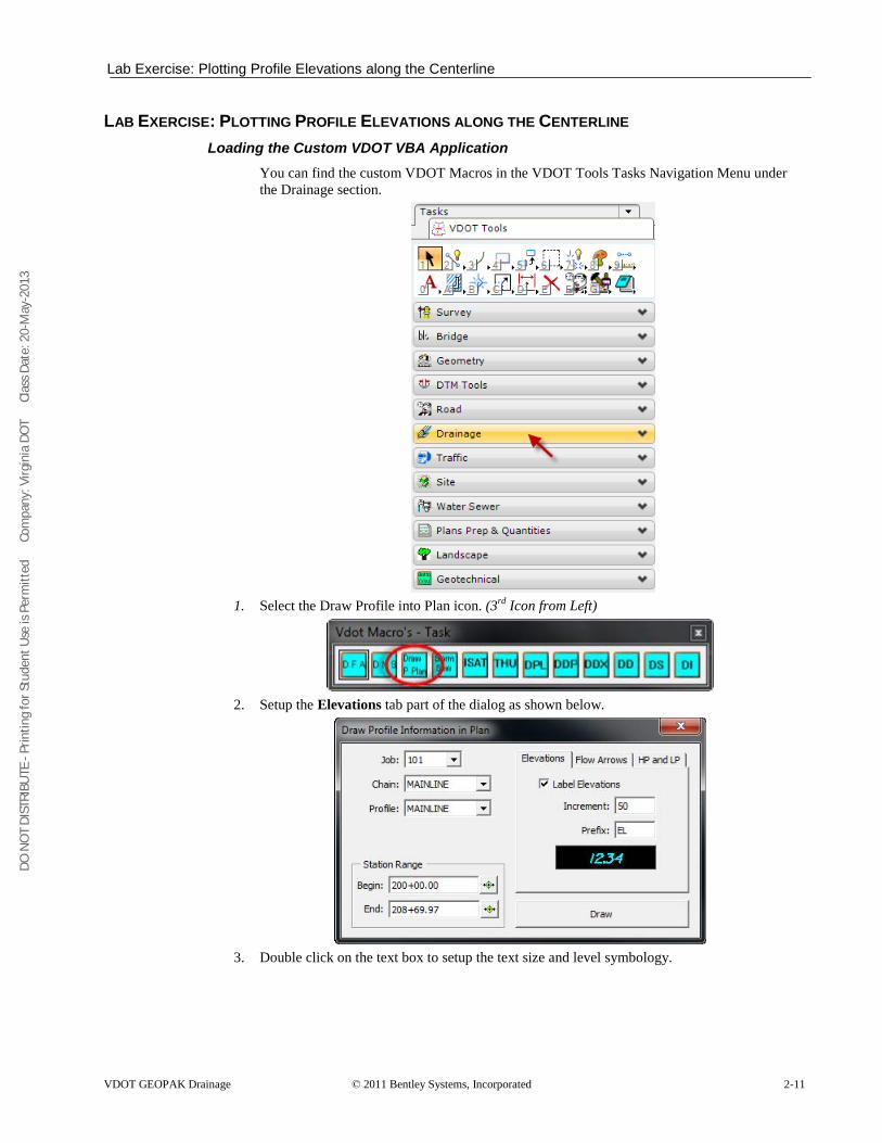
LAB EXERCISE: PLOTTING PROFILE ELEVATIONS ALONG THE CENTERLINE Loading the Custom VDOT VBA Application
You can find the custom VDOT Macros in the VDOT Tools Tasks Navigation Menu under the Drainage section.
1. Select the Draw Profile into Plan icon. (3rd
Icon from Left)
2. Setup the Elevations tab part of the dialog as shown below.
3. Double click on the text box to setup the text size and level symbology.
DO N
OT
DIST
RIBU
TE -
Prin
ting
for S
tude
nt U
se is
Per
mitt
ed
Co
mpa
ny: V
irgin
ia D
OT
C
lass
Dat
e: 2
0-M
ay-2
013
Lab Exercise: Plotting Profile Elevations along the Centerline
2-12 © 2011 Bentley Systems, Incorporated VDOT GEOPAK Drainage
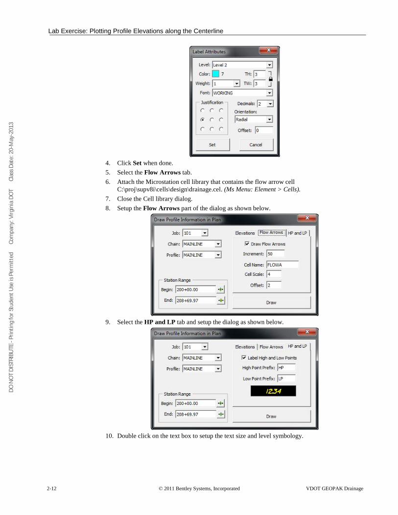
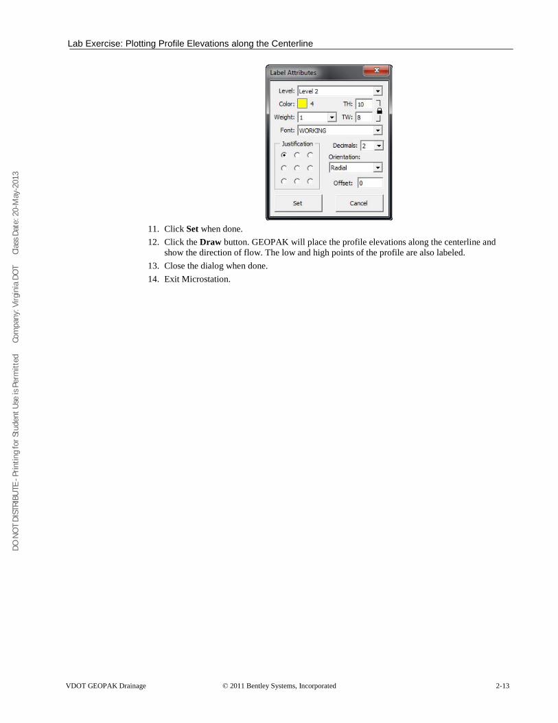
4. Click Set when done. 5. Select the Flow Arrows tab. 6. Attach the Microstation cell library that contains the flow arrow cell
C:\proj\supv8i\cells\design\drainage.cel. (Ms Menu: Element > Cells). 7. Close the Cell library dialog. 8. Setup the Flow Arrows part of the dialog as shown below.
9. Select the HP and LP tab and setup the dialog as shown below.
10. Double click on the text box to setup the text size and level symbology.
DO N
OT
DIST
RIBU
TE -
Prin
ting
for S
tude
nt U
se is
Per
mitt
ed
Co
mpa
ny: V
irgin
ia D
OT
C
lass
Dat
e: 2
0-M
ay-2
013
Lab Exercise: Plotting Profile Elevations along the Centerline
VDOT GEOPAK Drainage © 2011 Bentley Systems, Incorporated 2-13
11. Click Set when done. 12. Click the Draw button. GEOPAK will place the profile elevations along the centerline and
show the direction of flow. The low and high points of the profile are also labeled. 13. Close the dialog when done. 14. Exit Microstation.
DO N
OT
DIST
RIBU
TE -
Prin
ting
for S
tude
nt U
se is
Per
mitt
ed
Co
mpa
ny: V
irgin
ia D
OT
C
lass
Dat
e: 2
0-M
ay-2
013
Lab Exercise: Setting Up Land Use Areas
2-14 © 2011 Bentley Systems, Incorporated VDOT GEOPAK Drainage
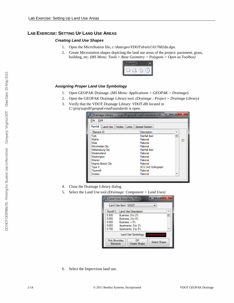
LAB EXERCISE: SETTING UP LAND USE AREAS Creating Land Use Shapes
1. Open the MicroStation file, c:\data\geo\VDOT\drain1\h17682da.dgn. 2. Create Microstation shapes depicting the land use areas of the project: pavement, grass,
building, etc. (MS Menu: Tools > Base Geometry > Polygons > Open as Toolbox)
Assigning Proper Land Use Symbology 1. Open GEOPAK Drainage. (MS Menu: Applications > GEOPAK > Drainage). 2. Open the GEOPAK Drainage Library tool. (Drainage : Project > Drainage Library) 3. Verify that the VDOT Drainage Library: VDOT.dlb located in
C:\proj\supv8i\geopak\road\standards is open.
4. Close the Drainage Library dialog. 5. Select the Land Use tool (Drainage: Component > Land Uses)
6. Select the Impervious land use.
DO N
OT
DIST
RIBU
TE -
Prin
ting
for S
tude
nt U
se is
Per
mitt
ed
Co
mpa
ny: V
irgin
ia D
OT
C
lass
Dat
e: 2
0-M
ay-2
013
Lab Exercise: Setting Up Land Use Areas
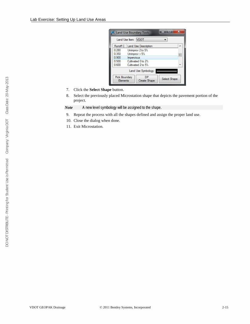
VDOT GEOPAK Drainage © 2011 Bentley Systems, Incorporated 2-15
7. Click the Select Shape button. 8. Select the previously placed Microstation shape that depicts the pavement portion of the
project.
Note A new level symbology will be assigned to the shape. 9. Repeat the process with all the shapes defined and assign the proper land use. 10. Close the dialog when done. 11. Exit Microstation.
DO N
OT
DIST
RIBU
TE -
Prin
ting
for S
tude
nt U
se is
Per
mitt
ed
Co
mpa
ny: V
irgin
ia D
OT
C
lass
Dat
e: 2
0-M
ay-2
013
Lab Exercise: Setting Up Land Use Areas
2-16 © 2011 Bentley Systems, Incorporated VDOT GEOPAK Drainage
DO N
OT
DIST
RIBU
TE -
Prin
ting
for S
tude
nt U
se is
Per
mitt
ed
Co
mpa
ny: V
irgin
ia D
OT
C
lass
Dat
e: 2
0-M
ay-2
013
VDOT GEOPAK Drainage © 2011 Bentley Systems, Incorporated 3-1
Starting a Drainage Project
OBJECTIVES In this chapter, you will learn more about:
• Various file types used within GEOPAK Drainage. • Creating a new GEOPAK Drainage Project file. • The general process for using GEOPAK Drainage to design a storm drain system.
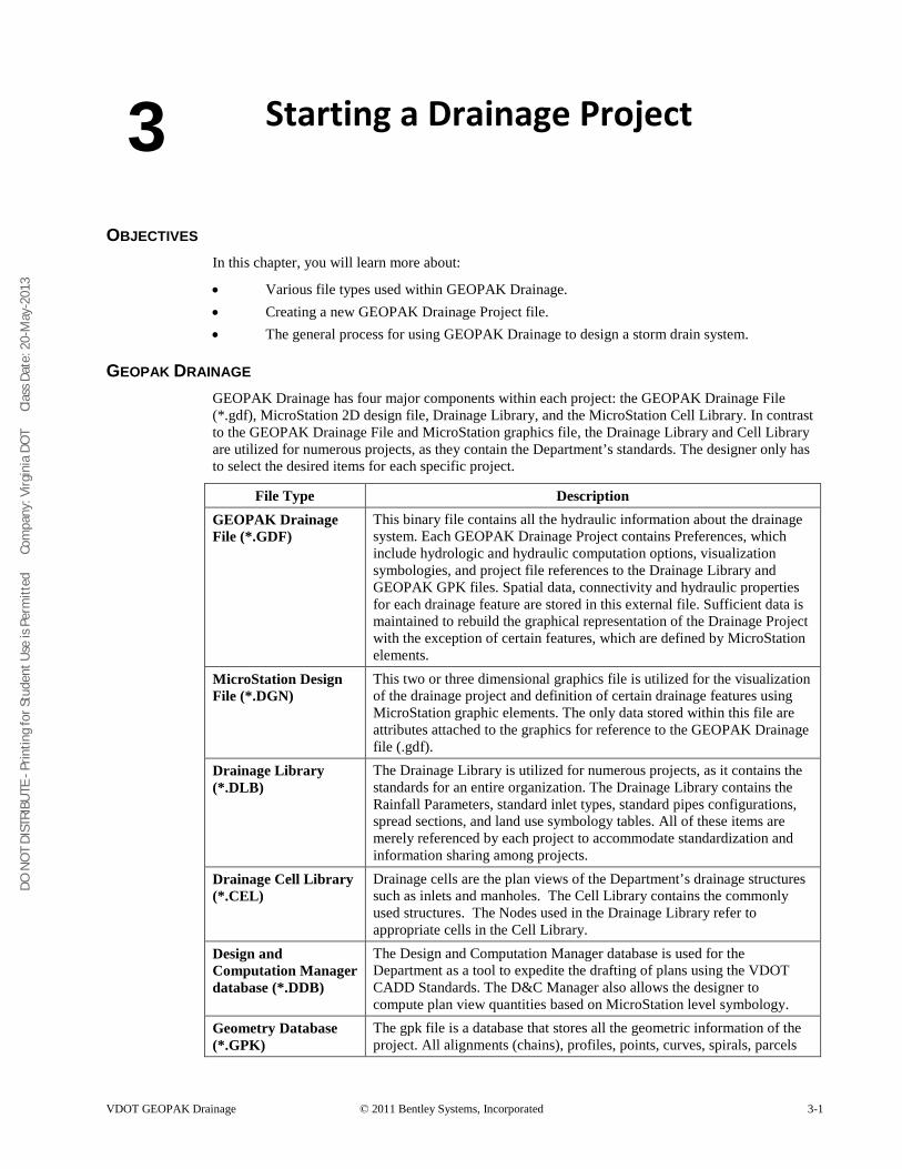
GEOPAK DRAINAGE GEOPAK Drainage has four major components within each project: the GEOPAK Drainage File (*.gdf), MicroStation 2D design file, Drainage Library, and the MicroStation Cell Library. In contrast to the GEOPAK Drainage File and MicroStation graphics file, the Drainage Library and Cell Library are utilized for numerous projects, as they contain the Department’s standards. The designer only has to select the desired items for each specific project.
File Type Description GEOPAK Drainage File (*.GDF)
This binary file contains all the hydraulic information about the drainage system. Each GEOPAK Drainage Project contains Preferences, which include hydrologic and hydraulic computation options, visualization symbologies, and project file references to the Drainage Library and GEOPAK GPK files. Spatial data, connectivity and hydraulic properties for each drainage feature are stored in this external file. Sufficient data is maintained to rebuild the graphical representation of the Drainage Project with the exception of certain features, which are defined by MicroStation elements.
MicroStation Design File (*.DGN)
This two or three dimensional graphics file is utilized for the visualization of the drainage project and definition of certain drainage features using MicroStation graphic elements. The only data stored within this file are attributes attached to the graphics for reference to the GEOPAK Drainage file (.gdf).
Drainage Library (*.DLB)
The Drainage Library is utilized for numerous projects, as it contains the standards for an entire organization. The Drainage Library contains the Rainfall Parameters, standard inlet types, standard pipes configurations, spread sections, and land use symbology tables. All of these items are merely referenced by each project to accommodate standardization and information sharing among projects.
Drainage Cell Library (*.CEL)
Drainage cells are the plan views of the Department’s drainage structures such as inlets and manholes. The Cell Library contains the commonly used structures. The Nodes used in the Drainage Library refer to appropriate cells in the Cell Library.
Design and Computation Manager database (*.DDB)
The Design and Computation Manager database is used for the Department as a tool to expedite the drafting of plans using the VDOT CADD Standards. The D&C Manager also allows the designer to compute plan view quantities based on MicroStation level symbology.
Geometry Database (*.GPK)
The gpk file is a database that stores all the geometric information of the project. All alignments (chains), profiles, points, curves, spirals, parcels
3
DO N
OT
DIST
RIBU
TE -
Prin
ting
for S
tude
nt U
se is
Per
mitt
ed
Co
mpa
ny: V
irgin
ia D
OT
C
lass
Dat
e: 2
0-M
ay-2
013
DRAINAGE COMPONENTS
3-2 © 2011 Bentley Systems, Incorporated VDOT GEOPAK Drainage
are saved into a single file per project. Then, Geopak Drainage can refer to the nodes location by station and offset from a particular chain and get or calculate elevations from a profile.
MicroStation Design File (*.DGN)
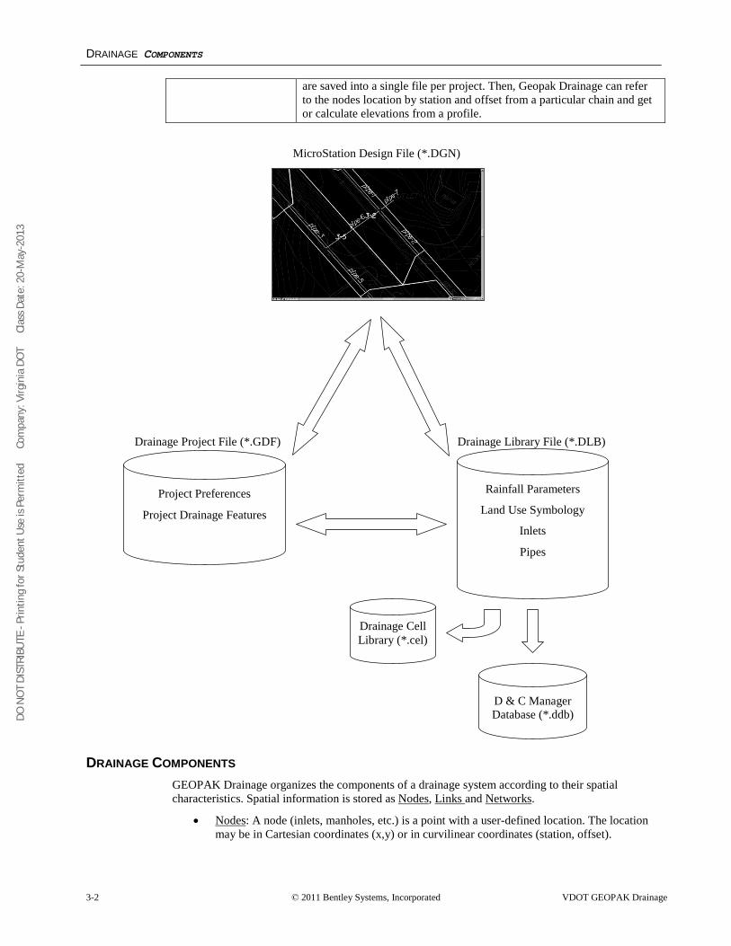
DRAINAGE COMPONENTS GEOPAK Drainage organizes the components of a drainage system according to their spatial characteristics. Spatial information is stored as Nodes, Links and Networks.
• Nodes: A node (inlets, manholes, etc.) is a point with a user-defined location. The location may be in Cartesian coordinates (x,y) or in curvilinear coordinates (station, offset).
Project Preferences
Project Drainage Features
Rainfall Parameters
Land Use Symbology
Inlets
Pipes
Drainage Project File (*.GDF) Drainage Library File (*.DLB)
Drainage Cell Library (*.cel)
D & C Manager Database (*.ddb)
DO N
OT
DIST
RIBU
TE -
Prin
ting
for S
tude
nt U
se is
Per
mitt
ed
Co
mpa
ny: V
irgin
ia D
OT
C
lass
Dat
e: 2
0-M
ay-2
013
MAIN MENU BAR
VDOT GEOPAK Drainage © 2011 Bentley Systems, Incorporated 3-3
• Links
•
: A Link represents a linear feature depicting a path connecting two nodes, traversing upstream to downstream. The path may be straight line or curvilinear (along a graphic element). Networks
Other associated components in GEOPAK Drainage include:
: A network is a system of interconnected nodes and links that form a system through which water can flow to a single outlet node. A drainage project accommodates any number of Networks.
• Areas: A drainage area can be represented by a closed boundary or simply keyed-in (acres or hectares). All flows from a single drainage area are tributary to a single Node. There is a one to one correspondence between a node and an area. Therefore areas and nodes share the same name (ID). A drainage area may contain multiple sub areas representing homogeneous features such as soil types and land uses (“C” values), thereby allowing composite "C" value calculations.
• Profiles: A profile represents a path connecting any two nodes in a Network. Profiles provide the visualization of profiles between any two nodes in a drainage network.
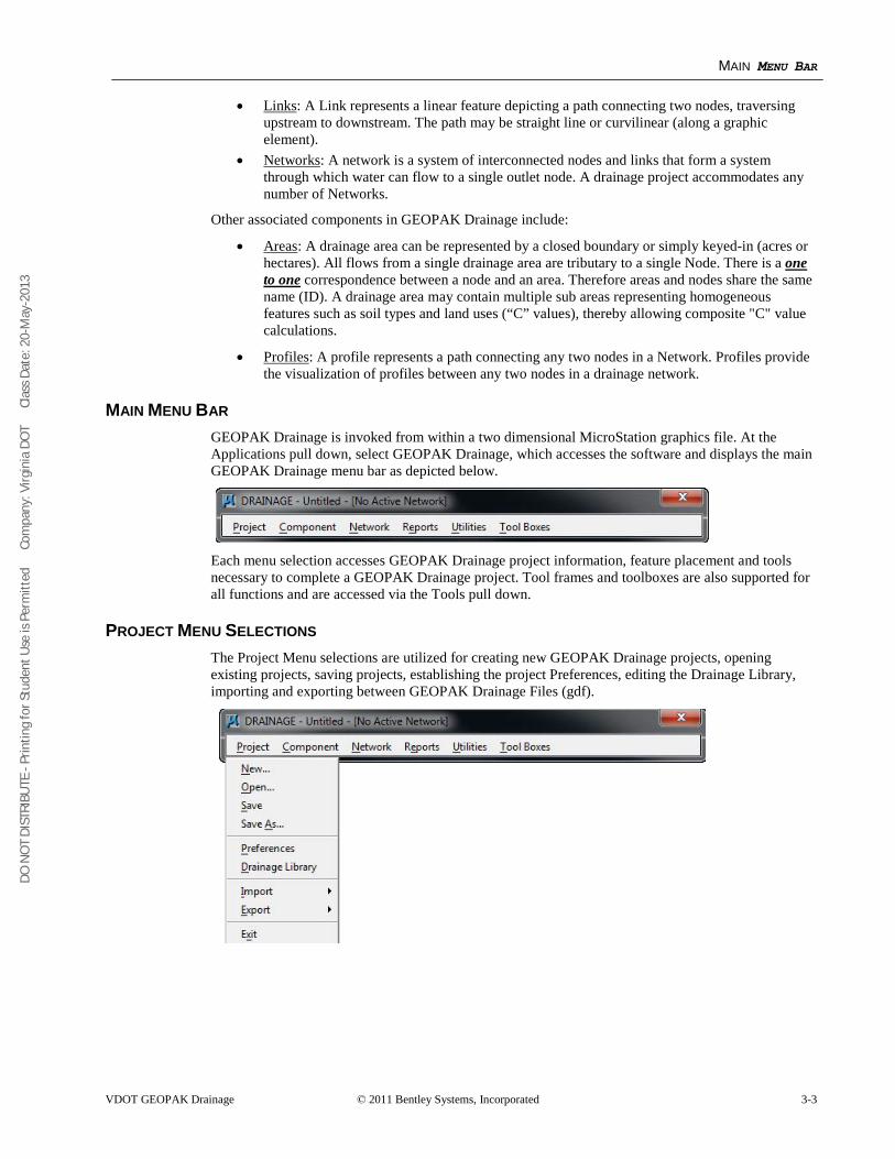
MAIN MENU BAR GEOPAK Drainage is invoked from within a two dimensional MicroStation graphics file. At the Applications pull down, select GEOPAK Drainage, which accesses the software and displays the main GEOPAK Drainage menu bar as depicted below.
Each menu selection accesses GEOPAK Drainage project information, feature placement and tools necessary to complete a GEOPAK Drainage project. Tool frames and toolboxes are also supported for all functions and are accessed via the Tools pull down.
PROJECT MENU SELECTIONS The Project Menu selections are utilized for creating new GEOPAK Drainage projects, opening existing projects, saving projects, establishing the project Preferences, editing the Drainage Library, importing and exporting between GEOPAK Drainage Files (gdf).
DO N
OT
DIST
RIBU
TE -
Prin
ting
for S
tude
nt U
se is
Per
mitt
ed
Co
mpa
ny: V
irgin
ia D
OT
C
lass
Dat
e: 2
0-M
ay-2
013
COMPONENT MENU SELECTIONS
3-4 © 2011 Bentley Systems, Incorporated VDOT GEOPAK Drainage
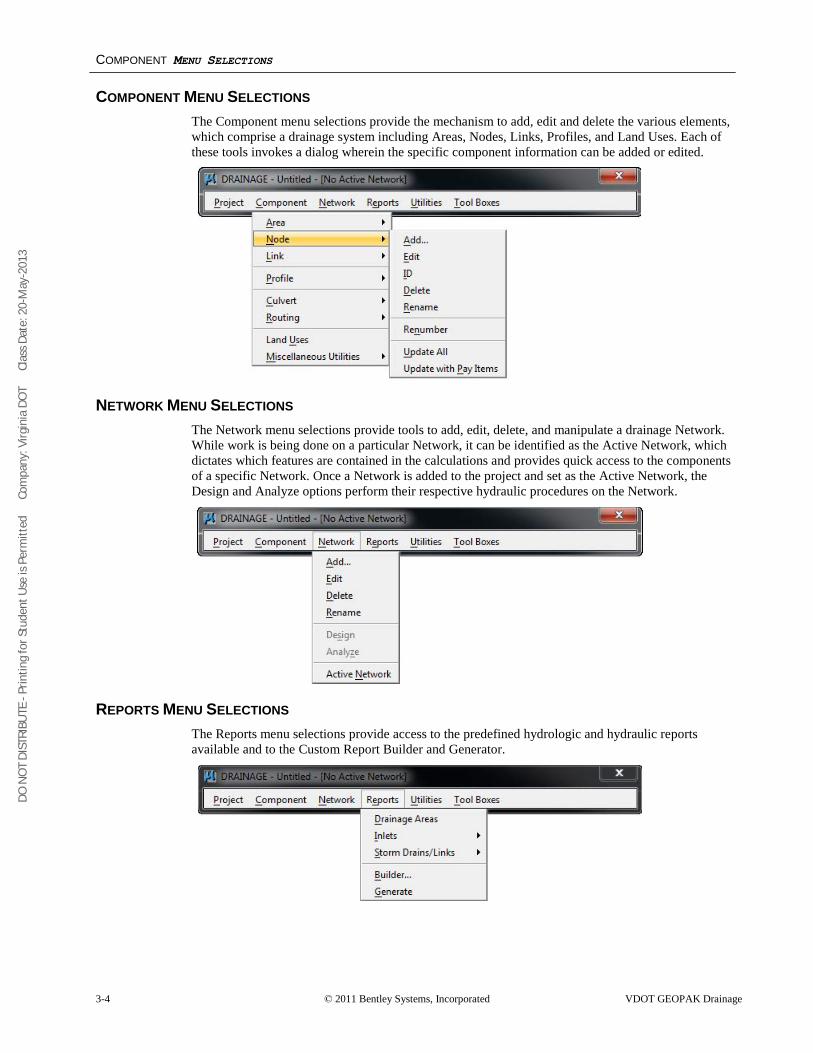
COMPONENT MENU SELECTIONS The Component menu selections provide the mechanism to add, edit and delete the various elements, which comprise a drainage system including Areas, Nodes, Links, Profiles, and Land Uses. Each of these tools invokes a dialog wherein the specific component information can be added or edited.
NETWORK MENU SELECTIONS The Network menu selections provide tools to add, edit, delete, and manipulate a drainage Network. While work is being done on a particular Network, it can be identified as the Active Network, which dictates which features are contained in the calculations and provides quick access to the components of a specific Network. Once a Network is added to the project and set as the Active Network, the Design and Analyze options perform their respective hydraulic procedures on the Network.
REPORTS MENU SELECTIONS The Reports menu selections provide access to the predefined hydrologic and hydraulic reports available and to the Custom Report Builder and Generator.
DO N
OT
DIST
RIBU
TE -
Prin
ting
for S
tude
nt U
se is
Per
mitt
ed
Co
mpa
ny: V
irgin
ia D
OT
C
lass
Dat
e: 2
0-M
ay-2
013
TOOLS MENU SELECTIONS
VDOT GEOPAK Drainage © 2011 Bentley Systems, Incorporated 3-5
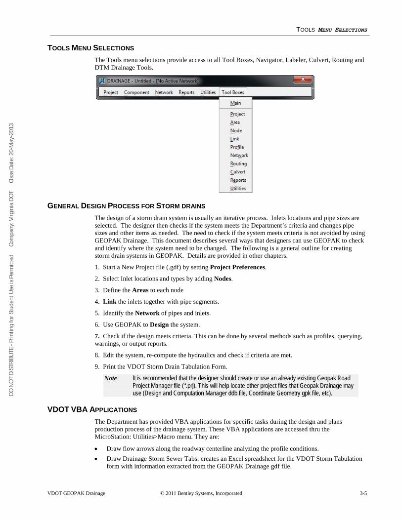
TOOLS MENU SELECTIONS The Tools menu selections provide access to all Tool Boxes, Navigator, Labeler, Culvert, Routing and DTM Drainage Tools.
GENERAL DESIGN PROCESS FOR STORM DRAINS The design of a storm drain system is usually an iterative process. Inlets locations and pipe sizes are selected. The designer then checks if the system meets the Department’s criteria and changes pipe sizes and other items as needed. The need to check if the system meets criteria is not avoided by using GEOPAK Drainage. This document describes several ways that designers can use GEOPAK to check and identify where the system need to be changed. The following is a general outline for creating storm drain systems in GEOPAK. Details are provided in other chapters.
1. Start a New Project file (.gdf) by setting Project Preferences.
2. Select Inlet locations and types by adding Nodes.
3. Define the Areas to each node
4. Link the inlets together with pipe segments.
5. Identify the Network of pipes and inlets.
6. Use GEOPAK to Design the system.
7. Check if the design meets criteria. This can be done by several methods such as profiles, querying, warnings, or output reports.
8. Edit the system, re-compute the hydraulics and check if criteria are met.
9. Print the VDOT Storm Drain Tabulation Form.
Note It is recommended that the designer should create or use an already existing Geopak Road Project Manager file (*.prj). This will help locate other project files that Geopak Drainage may use (Design and Computation Manager ddb file, Coordinate Geometry gpk file, etc).
VDOT VBA APPLICATIONS The Department has provided VBA applications for specific tasks during the design and plans production process of the drainage system. These VBA applications are accessed thru the MicroStation: Utilities>Macro menu. They are:
• Draw flow arrows along the roadway centerline analyzing the profile conditions. • Draw Drainage Storm Sewer Tabs: creates an Excel spreadsheet for the VDOT Storm Tabulation
form with information extracted from the GEOPAK Drainage gdf file.
DO N
OT
DIST
RIBU
TE -
Prin
ting
for S
tude
nt U
se is
Per
mitt
ed
Co
mpa
ny: V
irgin
ia D
OT
C
lass
Dat
e: 2
0-M
ay-2
013
ACCESSING GEOPAK DRAINAGE
3-6 © 2011 Bentley Systems, Incorporated VDOT GEOPAK Drainage
• Sketch of Geopak Drainage Network: creates a jpg image with a sketch (not to scale) of the selected drainage network.
• Draw flow directional arrows along the pipes.
ACCESSING GEOPAK DRAINAGE GEOPAK Drainage is invoked from within a two dimensional MicroStation graphics file. At the Applications pull down, select GEOPAK Drainage, which accesses the software and displays the Drainage application into the MicroStation pull-down menu.
Each menu selection accesses GEOPAK Drainage project information, feature placement and tools necessary to complete a GEOPAK Drainage project. Tool frames and toolboxes are also supported for all functions and are accessed via the Tools pull down.
GEOPAK Drainage always starts in an ‘Untitled’ project as noted in the MicroStation menu bar. Therefore it is necessary to always either create a new project or open an existing project prior to performing any other GEOPAK Drainage functions.
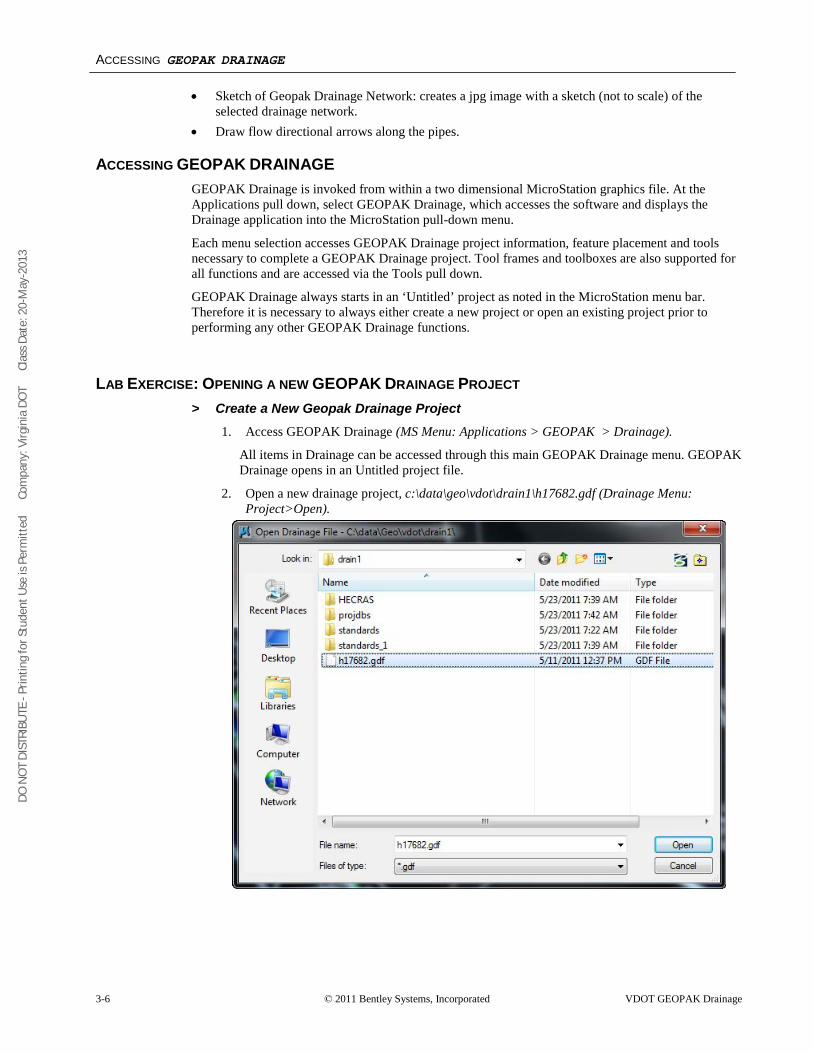
LAB EXERCISE: OPENING A NEW GEOPAK DRAINAGE PROJECT > Create a New Geopak Drainage Project
1. Access GEOPAK Drainage (MS Menu: Applications > GEOPAK > Drainage).
All items in Drainage can be accessed through this main GEOPAK Drainage menu. GEOPAK Drainage opens in an Untitled project file.
2. Open a new drainage project, c:\data\geo\vdot\drain1\h17682.gdf (Drainage Menu: Project>Open).
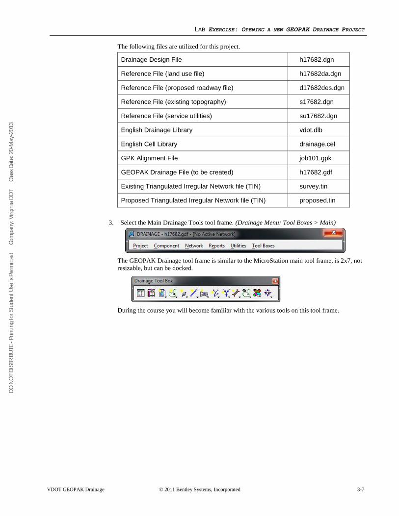
DO N
OT
DIST
RIBU
TE -
Prin
ting
for S
tude
nt U
se is
Per
mitt
ed
Co
mpa
ny: V
irgin
ia D
OT
C
lass
Dat
e: 2
0-M
ay-2
013
LAB EXERCISE: OPENING A NEW GEOPAK DRAINAGE PROJECT
VDOT GEOPAK Drainage © 2011 Bentley Systems, Incorporated 3-7
The following files are utilized for this project.
Drainage Design File h17682.dgn
Reference File (land use file) h17682da.dgn
Reference File (proposed roadway file) d17682des.dgn
Reference File (existing topography) s17682.dgn
Reference File (service utilities) su17682.dgn
English Drainage Library vdot.dlb
English Cell Library drainage.cel
GPK Alignment File job101.gpk
GEOPAK Drainage File (to be created) h17682.gdf
Existing Triangulated Irregular Network file (TIN) survey.tin
Proposed Triangulated Irregular Network file (TIN) proposed.tin
3. Select the Main Drainage Tools tool frame. (Drainage Menu: Tool Boxes > Main)
The GEOPAK Drainage tool frame is similar to the MicroStation main tool frame, is 2x7, not resizable, but can be docked.
During the course you will become familiar with the various tools on this tool frame.
DO N
OT
DIST
RIBU
TE -
Prin
ting
for S
tude
nt U
se is
Per
mitt
ed
Co
mpa
ny: V
irgin
ia D
OT
C
lass
Dat
e: 2
0-M
ay-2
013
LAB EXERCISE: OPENING A NEW GEOPAK DRAINAGE PROJECT
3-8 © 2011 Bentley Systems, Incorporated VDOT GEOPAK Drainage
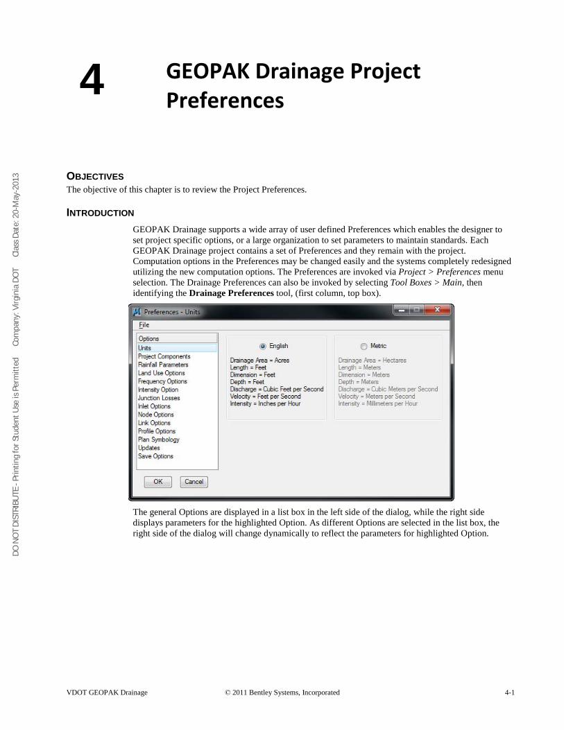
DO N
OT
DIST
RIBU
TE -
Prin
ting
for S
tude
nt U
se is
Per
mitt
ed
Co
mpa
ny: V
irgin
ia D
OT
C
lass
Dat
e: 2
0-M
ay-2
013
VDOT GEOPAK Drainage © 2011 Bentley Systems, Incorporated 4-1
GEOPAK Drainage Project Preferences
OBJECTIVES The objective of this chapter is to review the Project Preferences.
INTRODUCTION GEOPAK Drainage supports a wide array of user defined Preferences which enables the designer to set project specific options, or a large organization to set parameters to maintain standards. Each GEOPAK Drainage project contains a set of Preferences and they remain with the project. Computation options in the Preferences may be changed easily and the systems completely redesigned utilizing the new computation options. The Preferences are invoked via Project > Preferences menu selection. The Drainage Preferences can also be invoked by selecting Tool Boxes > Main, then identifying the Drainage Preferences tool, (first column, top box).
The general Options are displayed in a list box in the left side of the dialog, while the right side displays parameters for the highlighted Option. As different Options are selected in the list box, the right side of the dialog will change dynamically to reflect the parameters for highlighted Option.
4
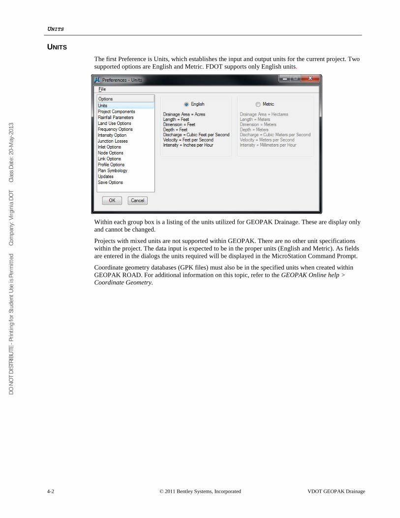
DO N
OT
DIST
RIBU
TE -
Prin
ting
for S
tude
nt U
se is
Per
mitt
ed
Co
mpa
ny: V
irgin
ia D
OT
C
lass
Dat
e: 2
0-M
ay-2
013
UNITS
4-2 © 2011 Bentley Systems, Incorporated VDOT GEOPAK Drainage
UNITS The first Preference is Units, which establishes the input and output units for the current project. Two supported options are English and Metric. FDOT supports only English units.
Within each group box is a listing of the units utilized for GEOPAK Drainage. These are display only and cannot be changed.
Projects with mixed units are not supported within GEOPAK. There are no other unit specifications within the project. The data input is expected to be in the proper units (English and Metric). As fields are entered in the dialogs the units required will be displayed in the MicroStation Command Prompt.
Coordinate geometry databases (GPK files) must also be in the specified units when created within GEOPAK ROAD. For additional information on this topic, refer to the GEOPAK Online help > Coordinate Geometry.
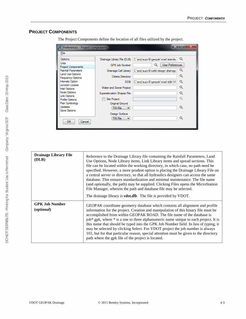
DO N
OT
DIST
RIBU
TE -
Prin
ting
for S
tude
nt U
se is
Per
mitt
ed
Co
mpa
ny: V
irgin
ia D
OT
C
lass
Dat
e: 2
0-M
ay-2
013
PROJECT COMPONENTS
VDOT GEOPAK Drainage © 2011 Bentley Systems, Incorporated 4-3
PROJECT COMPONENTS The Project Components define the location of all files utilized by the project.
Drainage Library File (DLB)
Reference to the Drainage Library file containing the Rainfall Parameters, Land Use Options, Node Library items, Link Library items and spread sections. This file can be located within the working directory, in which case, no path need be specified. However, a more prudent option is placing the Drainage Library File on a central server or directory, so that all hydraulics designers can access the same database. This ensures standardization and minimal maintenance. The file name (and optionally, the path) may be supplied. Clicking Files opens the MicroStation File Manager, wherein the path and database file may be selected.
The drainage library is vdot.dlb. The file is provided by VDOT.
GPK Job Number (optional)
GEOPAK coordinate geometry database which contains all alignment and profile information for the project. Creation and manipulation of this binary file must be accomplished from within GEOPAK ROAD. The file name of the database is job*.gpk, where * is a one to three alphanumeric name unique to each project. It is this name that should be typed into the GPK Job Number field. In lieu of typing, it may be selected by clicking Select. For VDOT project the job number is always 101, but for that particular reason, special attention must be given to the directory path where the gpk file of the project is located.
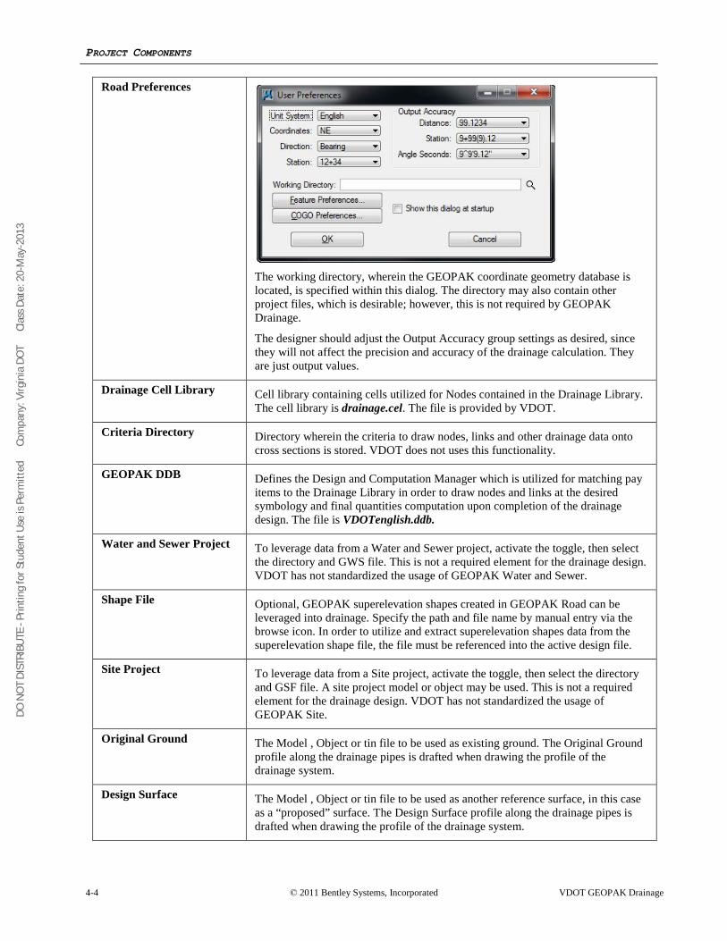
DO N
OT
DIST
RIBU
TE -
Prin
ting
for S
tude
nt U
se is
Per
mitt
ed
Co
mpa
ny: V
irgin
ia D
OT
C
lass
Dat
e: 2
0-M
ay-2
013
PROJECT COMPONENTS
4-4 © 2011 Bentley Systems, Incorporated VDOT GEOPAK Drainage
Road Preferences
The working directory, wherein the GEOPAK coordinate geometry database is located, is specified within this dialog. The directory may also contain other project files, which is desirable; however, this is not required by GEOPAK Drainage.
The designer should adjust the Output Accuracy group settings as desired, since they will not affect the precision and accuracy of the drainage calculation. They are just output values.
Drainage Cell Library Cell library containing cells utilized for Nodes contained in the Drainage Library. The cell library is drainage.cel. The file is provided by VDOT.
Criteria Directory Directory wherein the criteria to draw nodes, links and other drainage data onto cross sections is stored. VDOT does not uses this functionality.
GEOPAK DDB Defines the Design and Computation Manager which is utilized for matching pay items to the Drainage Library in order to draw nodes and links at the desired symbology and final quantities computation upon completion of the drainage design. The file is VDOTenglish.ddb.
Water and Sewer Project To leverage data from a Water and Sewer project, activate the toggle, then select the directory and GWS file. This is not a required element for the drainage design. VDOT has not standardized the usage of GEOPAK Water and Sewer.
Shape File
Optional, GEOPAK superelevation shapes created in GEOPAK Road can be leveraged into drainage. Specify the path and file name by manual entry via the browse icon. In order to utilize and extract superelevation shapes data from the superelevation shape file, the file must be referenced into the active design file.
Site Project
To leverage data from a Site project, activate the toggle, then select the directory and GSF file. A site project model or object may be used. This is not a required element for the drainage design. VDOT has not standardized the usage of GEOPAK Site.
Original Ground
The Model , Object or tin file to be used as existing ground. The Original Ground profile along the drainage pipes is drafted when drawing the profile of the drainage system.
Design Surface
The Model , Object or tin file to be used as another reference surface, in this case as a “proposed” surface. The Design Surface profile along the drainage pipes is drafted when drawing the profile of the drainage system.
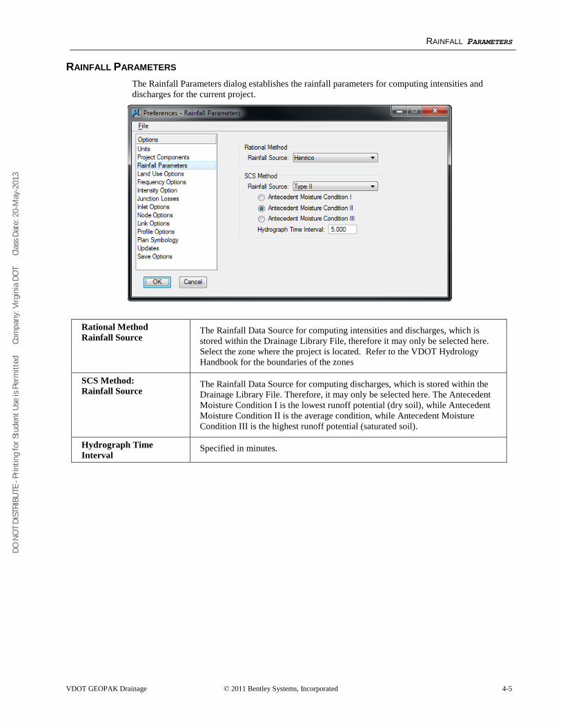
DO N
OT
DIST
RIBU
TE -
Prin
ting
for S
tude
nt U
se is
Per
mitt
ed
Co
mpa
ny: V
irgin
ia D
OT
C
lass
Dat
e: 2
0-M
ay-2
013
RAINFALL PARAMETERS
VDOT GEOPAK Drainage © 2011 Bentley Systems, Incorporated 4-5
RAINFALL PARAMETERS The Rainfall Parameters dialog establishes the rainfall parameters for computing intensities and discharges for the current project.
Rational Method Rainfall Source
The Rainfall Data Source for computing intensities and discharges, which is stored within the Drainage Library File, therefore it may only be selected here. Select the zone where the project is located. Refer to the VDOT Hydrology Handbook for the boundaries of the zones
SCS Method: Rainfall Source
The Rainfall Data Source for computing discharges, which is stored within the Drainage Library File. Therefore, it may only be selected here. The Antecedent Moisture Condition I is the lowest runoff potential (dry soil), while Antecedent Moisture Condition II is the average condition, while Antecedent Moisture Condition III is the highest runoff potential (saturated soil).
Hydrograph Time Interval
Specified in minutes.
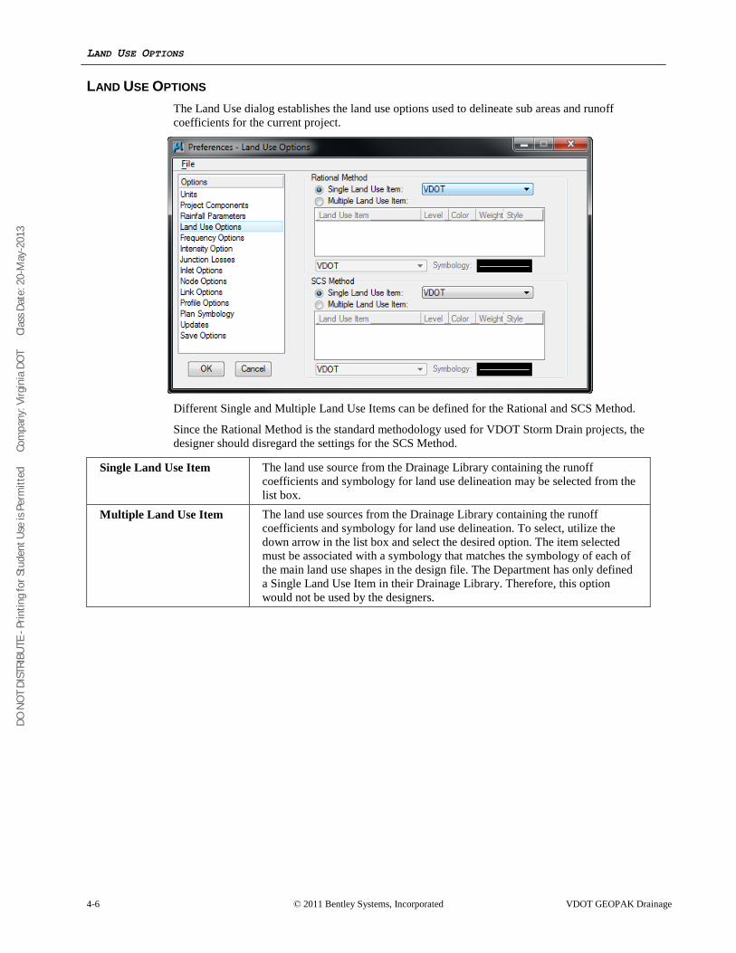
DO N
OT
DIST
RIBU
TE -
Prin
ting
for S
tude
nt U
se is
Per
mitt
ed
Co
mpa
ny: V
irgin
ia D
OT
C
lass
Dat
e: 2
0-M
ay-2
013
LAND USE OPTIONS
4-6 © 2011 Bentley Systems, Incorporated VDOT GEOPAK Drainage
LAND USE OPTIONS The Land Use dialog establishes the land use options used to delineate sub areas and runoff coefficients for the current project.
Different Single and Multiple Land Use Items can be defined for the Rational and SCS Method.
Since the Rational Method is the standard methodology used for VDOT Storm Drain projects, the designer should disregard the settings for the SCS Method.
Single Land Use Item The land use source from the Drainage Library containing the runoff coefficients and symbology for land use delineation may be selected from the list box.
Multiple Land Use Item The land use sources from the Drainage Library containing the runoff coefficients and symbology for land use delineation. To select, utilize the down arrow in the list box and select the desired option. The item selected must be associated with a symbology that matches the symbology of each of the main land use shapes in the design file. The Department has only defined a Single Land Use Item in their Drainage Library. Therefore, this option would not be used by the designers.
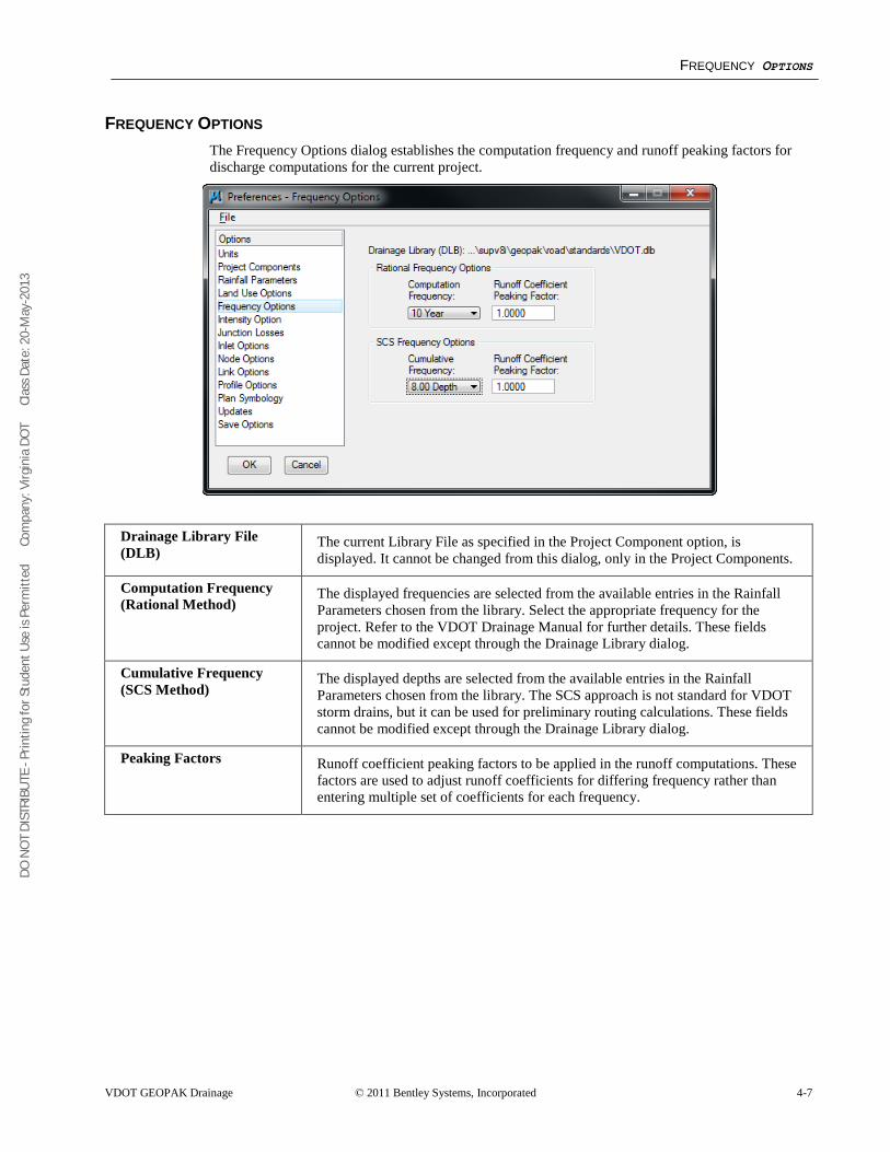
DO N
OT
DIST
RIBU
TE -
Prin
ting
for S
tude
nt U
se is
Per
mitt
ed
Co
mpa
ny: V
irgin
ia D
OT
C
lass
Dat
e: 2
0-M
ay-2
013
FREQUENCY OPTIONS
VDOT GEOPAK Drainage © 2011 Bentley Systems, Incorporated 4-7
FREQUENCY OPTIONS The Frequency Options dialog establishes the computation frequency and runoff peaking factors for discharge computations for the current project.
Drainage Library File (DLB)
The current Library File as specified in the Project Component option, is displayed. It cannot be changed from this dialog, only in the Project Components.
Computation Frequency (Rational Method)
The displayed frequencies are selected from the available entries in the Rainfall Parameters chosen from the library. Select the appropriate frequency for the project. Refer to the VDOT Drainage Manual for further details. These fields cannot be modified except through the Drainage Library dialog.
Cumulative Frequency (SCS Method)
The displayed depths are selected from the available entries in the Rainfall Parameters chosen from the library. The SCS approach is not standard for VDOT storm drains, but it can be used for preliminary routing calculations. These fields cannot be modified except through the Drainage Library dialog.
Peaking Factors Runoff coefficient peaking factors to be applied in the runoff computations. These factors are used to adjust runoff coefficients for differing frequency rather than entering multiple set of coefficients for each frequency.
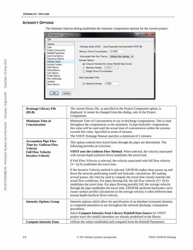
DO N
OT
DIST
RIBU
TE -
Prin
ting
for S
tude
nt U
se is
Per
mitt
ed
Co
mpa
ny: V
irgin
ia D
OT
C
lass
Dat
e: 2
0-M
ay-2
013
INTENSITY OPTIONS
4-8 © 2011 Bentley Systems, Incorporated VDOT GEOPAK Drainage
INTENSITY OPTIONS The Intensity Options dialog establishes the intensity computation options for the current project.
Drainage Library File (DLB)
The current library file, as specified in the Project Component option, is displayed. It cannot be changed from this dialog, only in the Project Components.
Minimum Time of Concentration
Minimum Time of Concentration to use in discharge computations. This is used throughout the computations as the minimum. In pipe hydraulic computations this value will be used until the actual time of concentration within the systems exceeds this value. Specified in terms of minutes. The VDOT Drainage Manual specifies a minimum of 5 minutes.
Accumulate Pipe Flow Time by: Uniform Flow Velocity Full Flow Velocity Iterative Velocity
This option controls how travel times through the pipes are determined. The following provides an overview.
VDOT uses the Uniform Flow Method. When selected, the velocity associated with normal depth (uniform flow) establishes the travel time.
If Full Flow Velocity is selected, the velocity associated with full flow velocity (V= Q/A) establishes the travel time.
If the Iterative Velocity method is selected, GEOPAK makes three passes up and down the network performing runoff and hydraulic calculations. By making several passes, the velocity used to compute the travel time closely matches the actual flow conditions. For pipes flowing full, the full flow velocity (V= Q/A) establishes the travel time. For pipes flowing partially full, the average velocity through the pipe establishes the travel time. GEOPAK performs backwater curve (water surface profile) calculations so the average velocity is often different than normal depth (uniform flow) velocity.
Intensity Options Group Intensity options which allow for specification of an absolute (constant) intensity or computed intensities to use throughout the network discharge computation procedures. Select Compute Intensity from Library Rainfall Data Source for VDOT project since the rainfall intensities are already predefined in the library.
Compute Intensity from Utilizes the values established and computed from the Rainfall Parameters
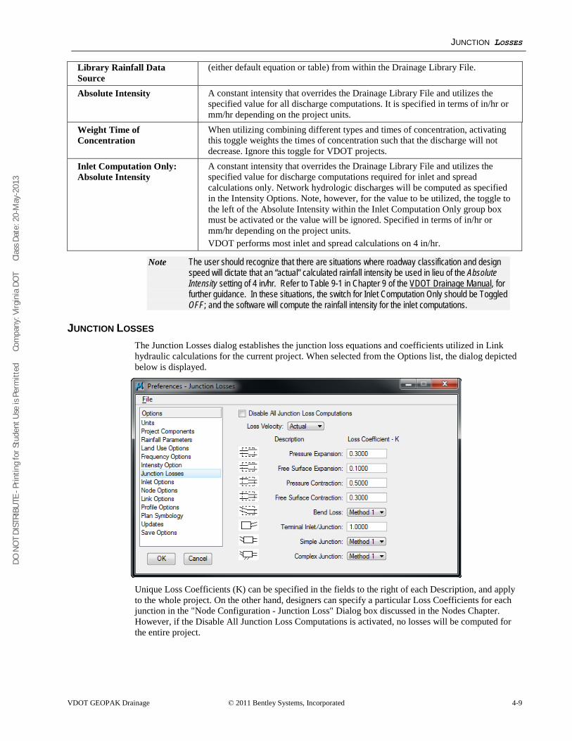
DO N
OT
DIST
RIBU
TE -
Prin
ting
for S
tude
nt U
se is
Per
mitt
ed
Co
mpa
ny: V
irgin
ia D
OT
C
lass
Dat
e: 2
0-M
ay-2
013
JUNCTION LOSSES
VDOT GEOPAK Drainage © 2011 Bentley Systems, Incorporated 4-9
Library Rainfall Data Source
(either default equation or table) from within the Drainage Library File.
Absolute Intensity A constant intensity that overrides the Drainage Library File and utilizes the specified value for all discharge computations. It is specified in terms of in/hr or mm/hr depending on the project units.
Weight Time of Concentration
When utilizing combining different types and times of concentration, activating this toggle weights the times of concentration such that the discharge will not decrease. Ignore this toggle for VDOT projects.
Inlet Computation Only: Absolute Intensity
A constant intensity that overrides the Drainage Library File and utilizes the specified value for discharge computations required for inlet and spread calculations only. Network hydrologic discharges will be computed as specified in the Intensity Options. Note, however, for the value to be utilized, the toggle to the left of the Absolute Intensity within the Inlet Computation Only group box must be activated or the value will be ignored. Specified in terms of in/hr or mm/hr depending on the project units. VDOT performs most inlet and spread calculations on 4 in/hr.
Note The user should recognize that there are situations where roadway classification and design speed will dictate that an “actual” calculated rainfall intensity be used in lieu of the Absolute Intensity setting of 4 in/hr. Refer to Table 9-1 in Chapter 9 of the VDOT Drainage Manual
JUNCTION LOSSES
, for further guidance. In these situations, the switch for Inlet Computation Only should be Toggled OFF; and the software will compute the rainfall intensity for the inlet computations.
The Junction Losses dialog establishes the junction loss equations and coefficients utilized in Link hydraulic calculations for the current project. When selected from the Options list, the dialog depicted below is displayed.
Unique Loss Coefficients (K) can be specified in the fields to the right of each Description, and apply to the whole project. On the other hand, designers can specify a particular Loss Coefficients for each junction in the "Node Configuration - Junction Loss" Dialog box discussed in the Nodes Chapter. However, if the Disable All Junction Loss Computations is activated, no losses will be computed for the entire project.
DO N
OT
DIST
RIBU
TE -
Prin
ting
for S
tude
nt U
se is
Per
mitt
ed
Co
mpa
ny: V
irgin
ia D
OT
C
lass
Dat
e: 2
0-M
ay-2
013
4-10 © 2011 Bentley Systems, Incorporated VDOT GEOPAK Drainage
Disable All Junction Loss Computations
If the toggle is active, no Junction Loss computations are calculated, regardless of the option selected in the Nodes - Junction dialog. Note if a single or small number of Junction Losses are not desired, an option is provided in the Nodes - Junction dialog to accomplish this. The toggle here applies to the entire project.
Loss Velocity Losses can be computed on Actual or Full Flow.
Pressure Expansion Loss coefficient to be used in pressure (full flow) expansions within the system.
Free Surface Expansion Loss coefficient to be used in free surface (partial flow) expansions within the system.
Pressure Contraction Loss coefficient to be used in pressure (full flow) contractions within the system.
Free Surface Contraction Loss coefficient to be used in free surface (partial flow) contractions within the system.
Bend Loss Specify the methodology and source of bend loss computations. Method 1 utilizes Modern Sewer Design, while Method 2 utilizes AASHTO methods.
Terminal Inlet / Junction Loss coefficient to be used at terminal inlets or junctions (no upstream pipes) within the system.
Simple Junction Specify the methodology for computing junction losses at simple junction (one pipe into the junction and one pipe out).
Complex Junction Specify the methodology for computing junction losses at complex junctions (more than one pipe in and only one pipe out).
INLET OPTIONS The Inlet Options dialog establishes the default inlet variables to use in the Node Configuration Properties dialog for each type of Inlet.
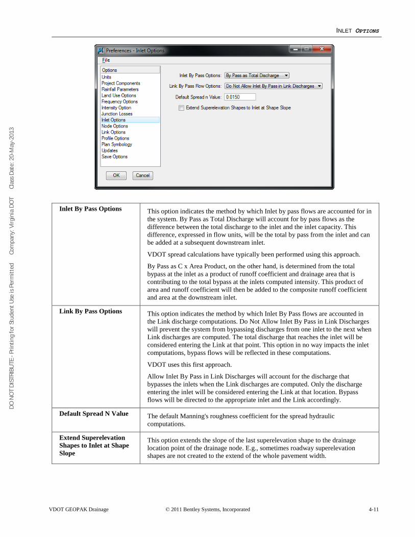
DO N
OT
DIST
RIBU
TE -
Prin
ting
for S
tude
nt U
se is
Per
mitt
ed
Co
mpa
ny: V
irgin
ia D
OT
C
lass
Dat
e: 2
0-M
ay-2
013
INLET OPTIONS
VDOT GEOPAK Drainage © 2011 Bentley Systems, Incorporated 4-11
Inlet By Pass Options This option indicates the method by which Inlet by pass flows are accounted for in the system. By Pass as Total Discharge will account for by pass flows as the difference between the total discharge to the inlet and the inlet capacity. This difference, expressed in flow units, will be the total by pass from the inlet and can be added at a subsequent downstream inlet.
VDOT spread calculations have typically been performed using this approach.
By Pass as C x Area Product, on the other hand, is determined from the total bypass at the inlet as a product of runoff coefficient and drainage area that is contributing to the total bypass at the inlets computed intensity. This product of area and runoff coefficient will then be added to the composite runoff coefficient and area at the downstream inlet.
Link By Pass Options This option indicates the method by which Inlet By Pass flows are accounted in the Link discharge computations. Do Not Allow Inlet By Pass in Link Discharges will prevent the system from bypassing discharges from one inlet to the next when Link discharges are computed. The total discharge that reaches the inlet will be considered entering the Link at that point. This option in no way impacts the inlet computations, bypass flows will be reflected in these computations.
VDOT uses this first approach.
Allow Inlet By Pass in Link Discharges will account for the discharge that bypasses the inlets when the Link discharges are computed. Only the discharge entering the inlet will be considered entering the Link at that location. Bypass flows will be directed to the appropriate inlet and the Link accordingly.
Default Spread N Value The default Manning's roughness coefficient for the spread hydraulic computations.
Extend Superelevation Shapes to Inlet at Shape Slope
This option extends the slope of the last superelevation shape to the drainage location point of the drainage node. E.g., sometimes roadway superelevation shapes are not created to the extend of the whole pavement width.
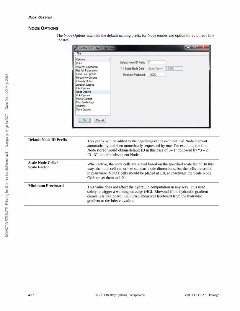
DO N
OT
DIST
RIBU
TE -
Prin
ting
for S
tude
nt U
se is
Per
mitt
ed
Co
mpa
ny: V
irgin
ia D
OT
C
lass
Dat
e: 2
0-M
ay-2
013
NODE OPTIONS
4-12 © 2011 Bentley Systems, Incorporated VDOT GEOPAK Drainage
NODE OPTIONS The Node Options establish the default naming prefix for Node entries and option for automatic link updates.
Default Node ID Prefix This prefix will be added to the beginning of the each defined Node element
automatically and then numerically sequenced by one. For example, the first Node stored would obtain default ID in this case of 3– 1” followed by “3 – 2”, “3– 3”, etc. for subsequent Nodes.
Scale Node Cells / Scale Factor
When active, the node cells are scaled based on the specified scale factor. In this way, the node cell can utilize standard node dimensions, but the cells are scaled in plan view. VDOT cells should be placed at 1.0, so inactivate the Scale Node Cells or set them to 1.0
Minimum Freeboard This value does not affect the hydraulic computation in any way. It is used solely to trigger a warning message (HGL Blowout) if the hydraulic gradient causes less free board. GEOPAK measures freeboard from the hydraulic gradient to the inlet elevation.
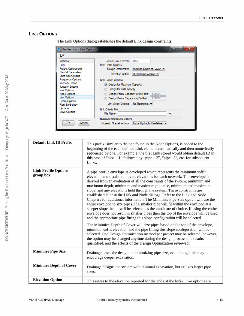
DO N
OT
DIST
RIBU
TE -
Prin
ting
for S
tude
nt U
se is
Per
mitt
ed
Co
mpa
ny: V
irgin
ia D
OT
C
lass
Dat
e: 2
0-M
ay-2
013
LINK OPTIONS
VDOT GEOPAK Drainage © 2011 Bentley Systems, Incorporated 4-13
LINK OPTIONS The Link Options dialog establishes the default Link design constraints.
Default Link ID Prefix This prefix, similar to the one found in the Node Options, is added to the beginning of the each defined Link element automatically and then numerically sequenced by one. For example, the first Link stored would obtain default ID in this case of “pipe – 1” followed by “pipe – 2”, “pipe– 3”, etc. for subsequent Links.
Link Profile Options group box
A pipe profile envelope is developed which represents the minimum soffit elevation and maximum invert elevations for each network. This envelope is derived from an evaluation of all the constraints of the system; minimum and maximum depth, minimum and maximum pipe rise, minimum and maximum slope, and any elevations held through the system. These constraints are established later in the Link and Node dialogs. Refer to the Link and Node Chapters for additional information. The Minimize Pipe Size option will use the entire envelope to size pipes. If a smaller pipe will fit within the envelope at a steeper slope then it will be selected as the candidate of choice. If using the entire envelope does not result in smaller pipes then the top of the envelope will be used and the appropriate pipe fitting this slope configuration will be selected.
The Minimize Depth of Cover will size pipes based on the top of the envelope, minimum soffit elevation and the pipe fitting this slope configuration will be selected. One Design Optimization method per project may be selected, however, the option may be changed anytime during the design process, the results quantified, and the effects of the Design Optimization reviewed.
Minimize Pipe Size Drainage bases the design on minimizing pipe size, even though this may encourage deeper excavation.
Minimize Depth of Cover Drainage designs the system with minimal excavation, but utilizes larger pipe sizes.
Elevation Option This refers to the elevation reported for the ends of the links. Two options are
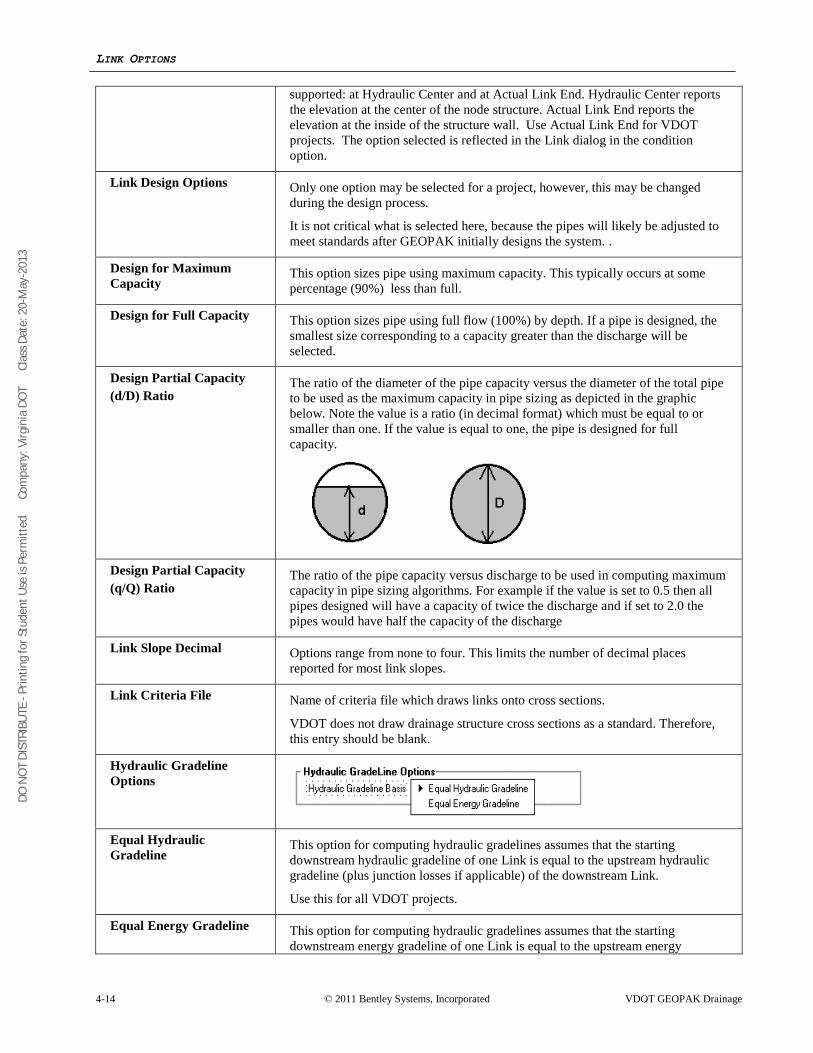
DO N
OT
DIST
RIBU
TE -
Prin
ting
for S
tude
nt U
se is
Per
mitt
ed
Co
mpa
ny: V
irgin
ia D
OT
C
lass
Dat
e: 2
0-M
ay-2
013
LINK OPTIONS
4-14 © 2011 Bentley Systems, Incorporated VDOT GEOPAK Drainage
supported: at Hydraulic Center and at Actual Link End. Hydraulic Center reports the elevation at the center of the node structure. Actual Link End reports the elevation at the inside of the structure wall. Use Actual Link End for VDOT projects. The option selected is reflected in the Link dialog in the condition option.
Link Design Options Only one option may be selected for a project, however, this may be changed during the design process.
It is not critical what is selected here, because the pipes will likely be adjusted to meet standards after GEOPAK initially designs the system. .
Design for Maximum Capacity
This option sizes pipe using maximum capacity. This typically occurs at some percentage (90%) less than full.
Design for Full Capacity This option sizes pipe using full flow (100%) by depth. If a pipe is designed, the smallest size corresponding to a capacity greater than the discharge will be selected.
Design Partial Capacity (d/D) Ratio
The ratio of the diameter of the pipe capacity versus the diameter of the total pipe to be used as the maximum capacity in pipe sizing as depicted in the graphic below. Note the value is a ratio (in decimal format) which must be equal to or smaller than one. If the value is equal to one, the pipe is designed for full capacity.
Design Partial Capacity (q/Q) Ratio
The ratio of the pipe capacity versus discharge to be used in computing maximum capacity in pipe sizing algorithms. For example if the value is set to 0.5 then all pipes designed will have a capacity of twice the discharge and if set to 2.0 the pipes would have half the capacity of the discharge
Link Slope Decimal Options range from none to four. This limits the number of decimal places reported for most link slopes.
Link Criteria File Name of criteria file which draws links onto cross sections.
VDOT does not draw drainage structure cross sections as a standard. Therefore, this entry should be blank.
Hydraulic Gradeline Options
Equal Hydraulic Gradeline
This option for computing hydraulic gradelines assumes that the starting downstream hydraulic gradeline of one Link is equal to the upstream hydraulic gradeline (plus junction losses if applicable) of the downstream Link.
Use this for all VDOT projects.
Equal Energy Gradeline This option for computing hydraulic gradelines assumes that the starting downstream energy gradeline of one Link is equal to the upstream energy
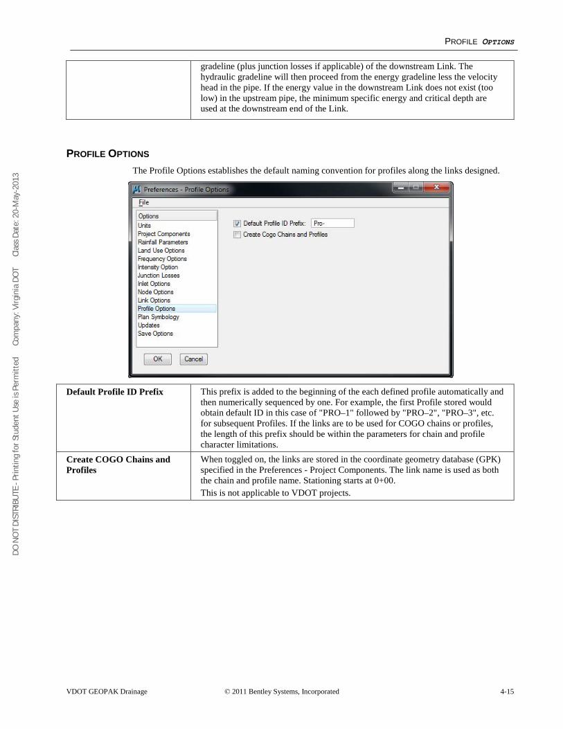
DO N
OT
DIST
RIBU
TE -
Prin
ting
for S
tude
nt U
se is
Per
mitt
ed
Co
mpa
ny: V
irgin
ia D
OT
C
lass
Dat
e: 2
0-M
ay-2
013
PROFILE OPTIONS
VDOT GEOPAK Drainage © 2011 Bentley Systems, Incorporated 4-15
gradeline (plus junction losses if applicable) of the downstream Link. The hydraulic gradeline will then proceed from the energy gradeline less the velocity head in the pipe. If the energy value in the downstream Link does not exist (too low) in the upstream pipe, the minimum specific energy and critical depth are used at the downstream end of the Link.
PROFILE OPTIONS The Profile Options establishes the default naming convention for profiles along the links designed.
Default Profile ID Prefix
This prefix is added to the beginning of the each defined profile automatically and then numerically sequenced by one. For example, the first Profile stored would obtain default ID in this case of "PRO–1" followed by "PRO–2", "PRO–3", etc. for subsequent Profiles. If the links are to be used for COGO chains or profiles, the length of this prefix should be within the parameters for chain and profile character limitations.
Create COGO Chains and Profiles
When toggled on, the links are stored in the coordinate geometry database (GPK) specified in the Preferences - Project Components. The link name is used as both the chain and profile name. Stationing starts at 0+00. This is not applicable to VDOT projects.
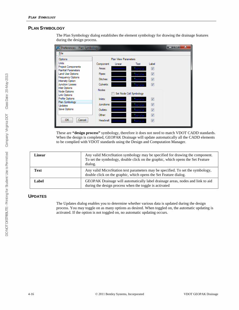
DO N
OT
DIST
RIBU
TE -
Prin
ting
for S
tude
nt U
se is
Per
mitt
ed
Co
mpa
ny: V
irgin
ia D
OT
C
lass
Dat
e: 2
0-M
ay-2
013
PLAN SYMBOLOGY
4-16 © 2011 Bentley Systems, Incorporated VDOT GEOPAK Drainage
PLAN SYMBOLOGY The Plan Symbology dialog establishes the element symbology for drawing the drainage features during the design process.
These are “design process” symbology, therefore it does not need to match VDOT CADD standards. When the design is completed, GEOPAK Drainage will update automatically all the CADD elements to be complied with VDOT standards using the Design and Computation Manager.
Linear Any valid MicroStation symbology may be specified for drawing the component.
To set the symbology, double click on the graphic, which opens the Set Feature dialog.
Text Any valid MicroStation text parameters may be specified. To set the symbology, double click on the graphic, which opens the Set Feature dialog.
Label GEOPAK Drainage will automatically label drainage areas, nodes and link to aid during the design process when the toggle is activated
UPDATES The Updates dialog enables you to determine whether various data is updated during the design process. You may toggle on as many options as desired. When toggled on, the automatic updating is activated. If the option is not toggled on, no automatic updating occurs.
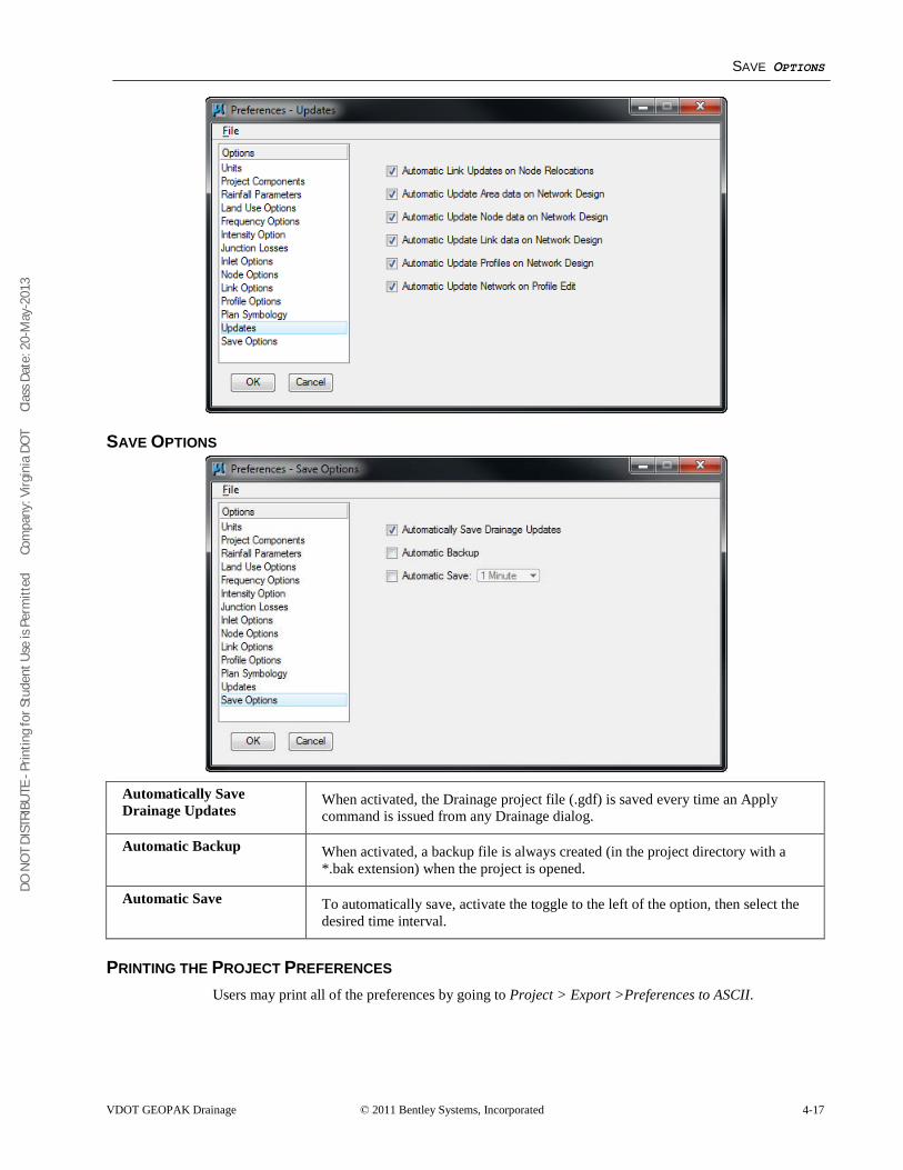
DO N
OT
DIST
RIBU
TE -
Prin
ting
for S
tude
nt U
se is
Per
mitt
ed
Co
mpa
ny: V
irgin
ia D
OT
C
lass
Dat
e: 2
0-M
ay-2
013
SAVE OPTIONS
VDOT GEOPAK Drainage © 2011 Bentley Systems, Incorporated 4-17
SAVE OPTIONS
Automatically Save Drainage Updates
When activated, the Drainage project file (.gdf) is saved every time an Apply command is issued from any Drainage dialog.
Automatic Backup When activated, a backup file is always created (in the project directory with a *.bak extension) when the project is opened.
Automatic Save To automatically save, activate the toggle to the left of the option, then select the desired time interval.
PRINTING THE PROJECT PREFERENCES Users may print all of the preferences by going to Project > Export >Preferences to ASCII.
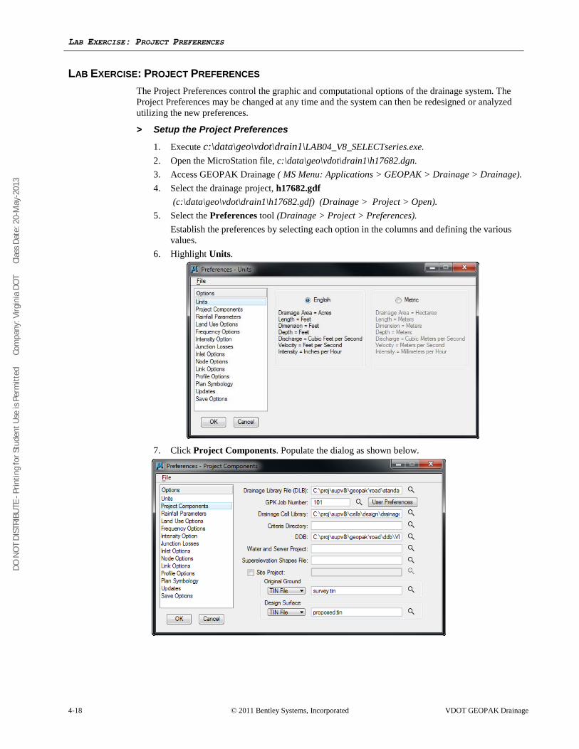
DO N
OT
DIST
RIBU
TE -
Prin
ting
for S
tude
nt U
se is
Per
mitt
ed
Co
mpa
ny: V
irgin
ia D
OT
C
lass
Dat
e: 2
0-M
ay-2
013
LAB EXERCISE: PROJECT PREFERENCES
4-18 © 2011 Bentley Systems, Incorporated VDOT GEOPAK Drainage
LAB EXERCISE: PROJECT PREFERENCES The Project Preferences control the graphic and computational options of the drainage system. The Project Preferences may be changed at any time and the system can then be redesigned or analyzed utilizing the new preferences.
> Setup the Project Preferences
1. Execute c:\data\geo\vdot\drain1\LAB04_V8_SELECTseries.exe. 2. Open the MicroStation file, c:\data\geo\vdot\drain1\h17682.dgn. 3. Access GEOPAK Drainage ( MS Menu: Applications > GEOPAK > Drainage > Drainage). 4. Select the drainage project, h17682.gdf
(c:\data\geo\vdot\drain1\h17682.gdf) (Drainage > Project > Open). 5. Select the Preferences tool (Drainage > Project > Preferences).
Establish the preferences by selecting each option in the columns and defining the various values.
6. Highlight Units.
7. Click Project Components. Populate the dialog as shown below.
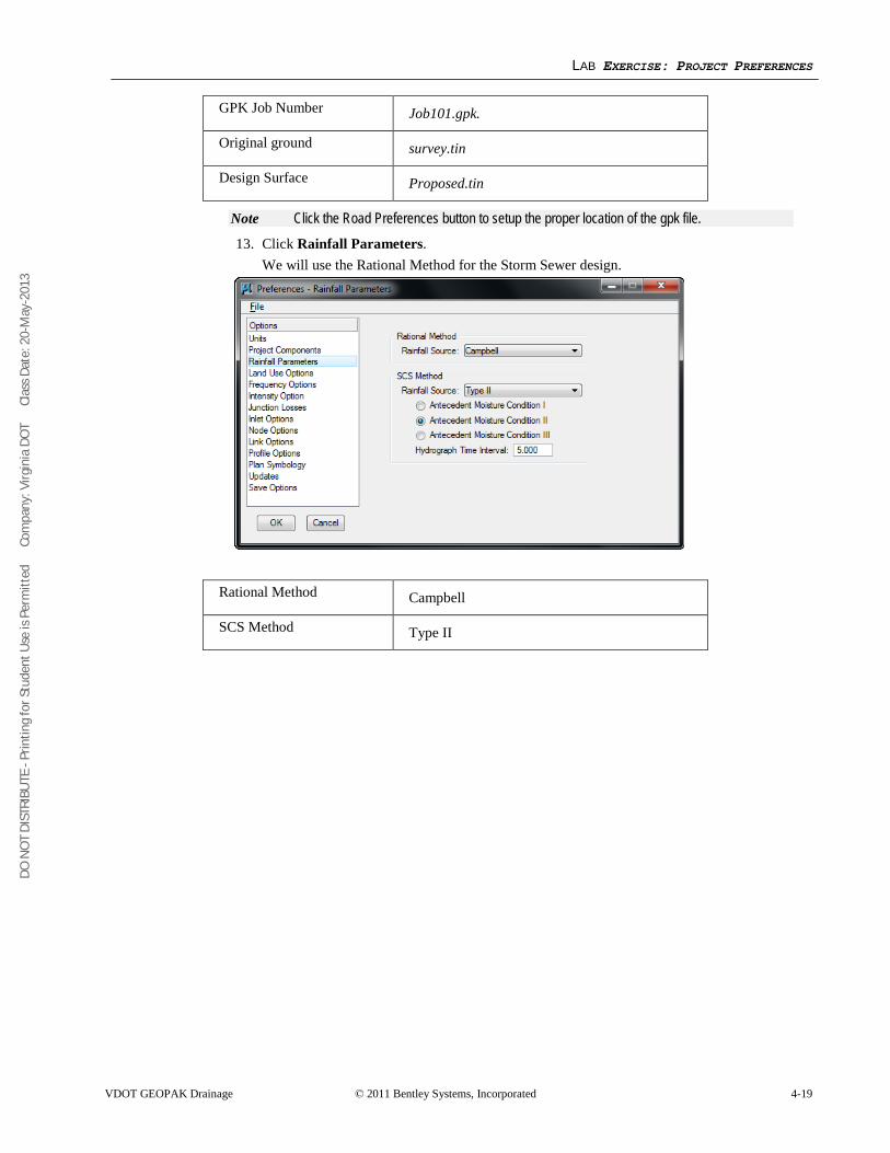
DO N
OT
DIST
RIBU
TE -
Prin
ting
for S
tude
nt U
se is
Per
mitt
ed
Co
mpa
ny: V
irgin
ia D
OT
C
lass
Dat
e: 2
0-M
ay-2
013
LAB EXERCISE: PROJECT PREFERENCES
VDOT GEOPAK Drainage © 2011 Bentley Systems, Incorporated 4-19
GPK Job Number Job101.gpk.
Original ground survey.tin
Design Surface Proposed.tin
Note Click the Road Preferences button to setup the proper location of the gpk file.
13. Click Rainfall Parameters. We will use the Rational Method for the Storm Sewer design.
Rational Method Campbell
SCS Method Type II
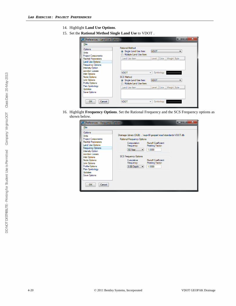
DO N
OT
DIST
RIBU
TE -
Prin
ting
for S
tude
nt U
se is
Per
mitt
ed
Co
mpa
ny: V
irgin
ia D
OT
C
lass
Dat
e: 2
0-M
ay-2
013
LAB EXERCISE: PROJECT PREFERENCES
4-20 © 2011 Bentley Systems, Incorporated VDOT GEOPAK Drainage
14. Highlight Land Use Options. 15. Set the Rational Method Single Land Use to VDOT .
16. Highlight Frequency Options. Set the Rational Frequency and the SCS Frequency options as
shown below.
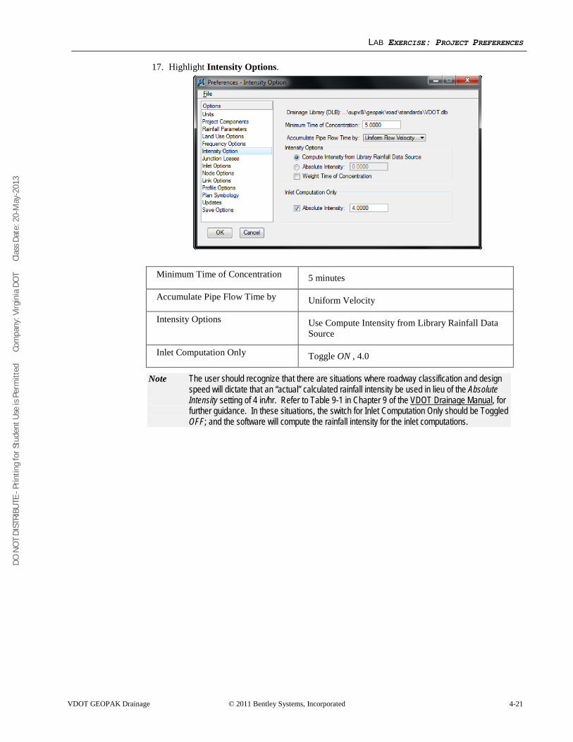
DO N
OT
DIST
RIBU
TE -
Prin
ting
for S
tude
nt U
se is
Per
mitt
ed
Co
mpa
ny: V
irgin
ia D
OT
C
lass
Dat
e: 2
0-M
ay-2
013
LAB EXERCISE: PROJECT PREFERENCES
VDOT GEOPAK Drainage © 2011 Bentley Systems, Incorporated 4-21
17. Highlight Intensity Options.
Minimum Time of Concentration 5 minutes
Accumulate Pipe Flow Time by Uniform Velocity
Intensity Options Use Compute Intensity from Library Rainfall Data Source
Inlet Computation Only Toggle ON , 4.0
Note The user should recognize that there are situations where roadway classification and design speed will dictate that an “actual” calculated rainfall intensity be used in lieu of the Absolute Intensity setting of 4 in/hr. Refer to Table 9-1 in Chapter 9 of the VDOT Drainage Manual
, for further guidance. In these situations, the switch for Inlet Computation Only should be Toggled OFF; and the software will compute the rainfall intensity for the inlet computations.
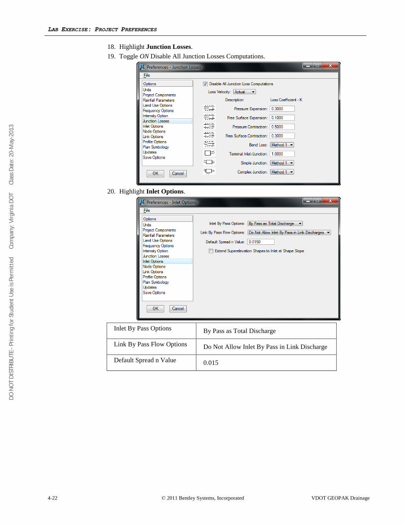
DO N
OT
DIST
RIBU
TE -
Prin
ting
for S
tude
nt U
se is
Per
mitt
ed
Co
mpa
ny: V
irgin
ia D
OT
C
lass
Dat
e: 2
0-M
ay-2
013
LAB EXERCISE: PROJECT PREFERENCES
4-22 © 2011 Bentley Systems, Incorporated VDOT GEOPAK Drainage
18. Highlight Junction Losses. 19. Toggle ON Disable All Junction Losses Computations.
20. Highlight Inlet Options.
Inlet By Pass Options By Pass as Total Discharge
Link By Pass Flow Options Do Not Allow Inlet By Pass in Link Discharge
Default Spread n Value 0.015
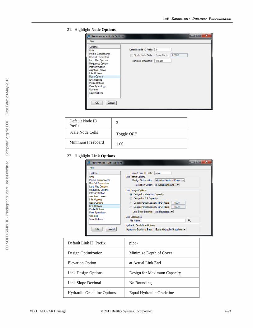
DO N
OT
DIST
RIBU
TE -
Prin
ting
for S
tude
nt U
se is
Per
mitt
ed
Co
mpa
ny: V
irgin
ia D
OT
C
lass
Dat
e: 2
0-M
ay-2
013
LAB EXERCISE: PROJECT PREFERENCES
VDOT GEOPAK Drainage © 2011 Bentley Systems, Incorporated 4-23
21. Highlight Node Options.
22. Highlight Link Options.
Default Link ID Prefix pipe-
Design Optimization Minimize Depth of Cover
Elevation Option at Actual Link End
Link Design Options Design for Maximum Capacity
Link Slope Decimal No Rounding
Hydraulic Gradeline Options Equal Hydraulic Gradeline
Default Node ID Prefix
3-
Scale Node Cells Toggle OFF
Minimum Freeboard 1.00
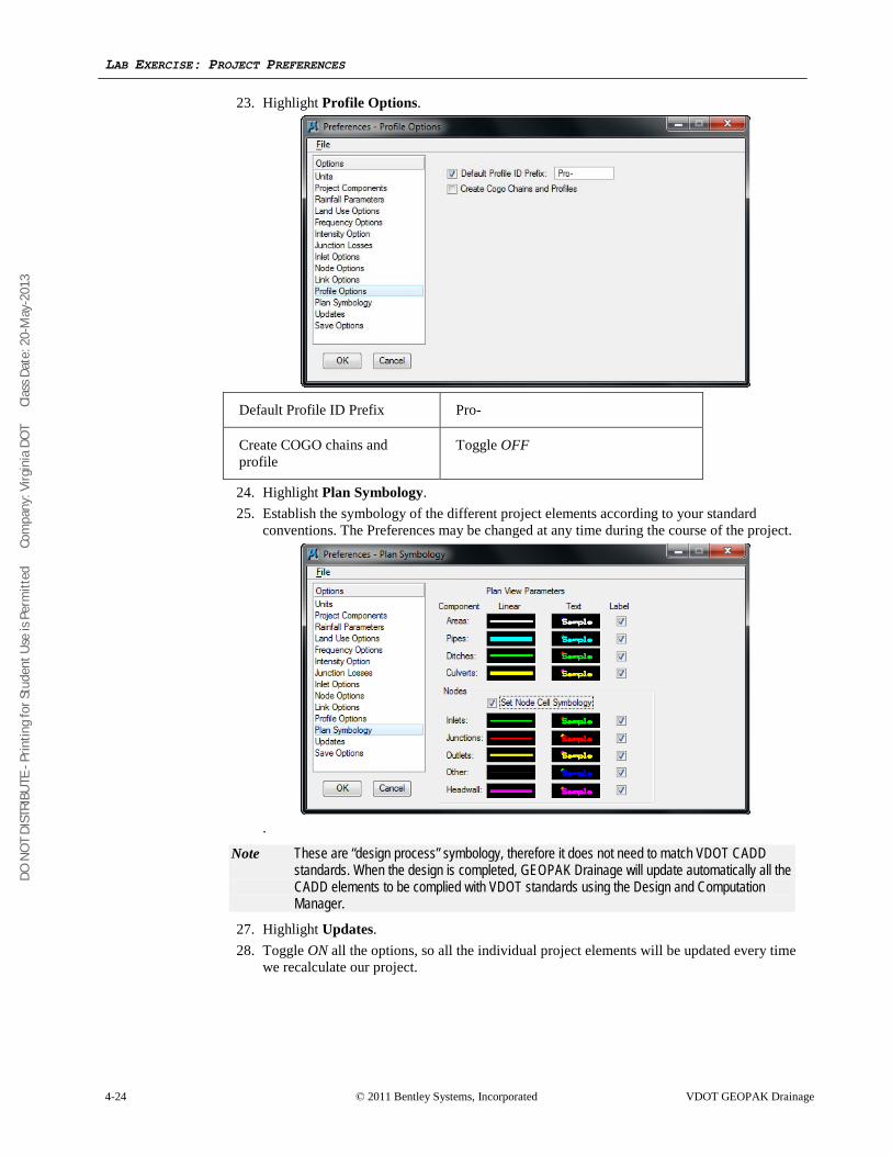
DO N
OT
DIST
RIBU
TE -
Prin
ting
for S
tude
nt U
se is
Per
mitt
ed
Co
mpa
ny: V
irgin
ia D
OT
C
lass
Dat
e: 2
0-M
ay-2
013
LAB EXERCISE: PROJECT PREFERENCES
4-24 © 2011 Bentley Systems, Incorporated VDOT GEOPAK Drainage
23. Highlight Profile Options.
Default Profile ID Prefix Pro-
Create COGO chains and profile
Toggle OFF
24. Highlight Plan Symbology. 25. Establish the symbology of the different project elements according to your standard
conventions. The Preferences may be changed at any time during the course of the project.
.
Note These are “design process” symbology, therefore it does not need to match VDOT CADD standards. When the design is completed, GEOPAK Drainage will update automatically all the CADD elements to be complied with VDOT standards using the Design and Computation Manager.
27. Highlight Updates. 28. Toggle ON all the options, so all the individual project elements will be updated every time
we recalculate our project.
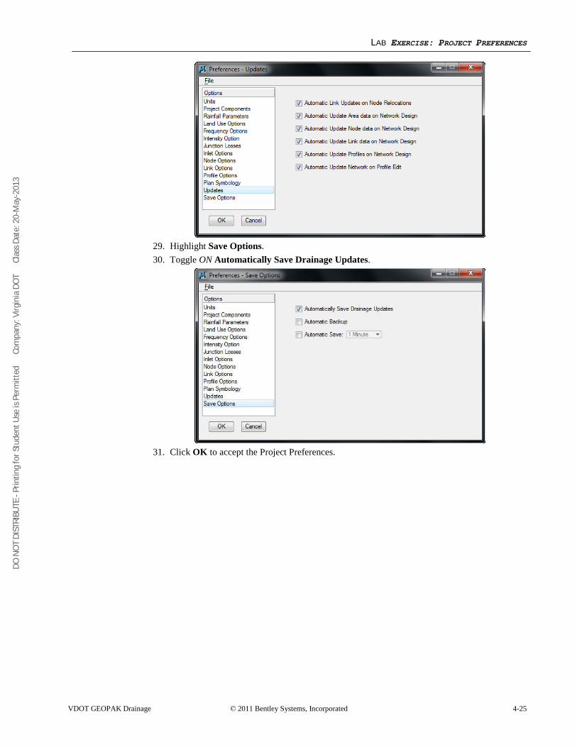
DO N
OT
DIST
RIBU
TE -
Prin
ting
for S
tude
nt U
se is
Per
mitt
ed
Co
mpa
ny: V
irgin
ia D
OT
C
lass
Dat
e: 2
0-M
ay-2
013
LAB EXERCISE: PROJECT PREFERENCES
VDOT GEOPAK Drainage © 2011 Bentley Systems, Incorporated 4-25
29. Highlight Save Options. 30. Toggle ON Automatically Save Drainage Updates.
31. Click OK to accept the Project Preferences.
DO N
OT
DIST
RIBU
TE -
Prin
ting
for S
tude
nt U
se is
Per
mitt
ed
Co
mpa
ny: V
irgin
ia D
OT
C
lass
Dat
e: 2
0-M
ay-2
013
LAB EXERCISE: PROJECT PREFERENCES
4-26 © 2011 Bentley Systems, Incorporated VDOT GEOPAK Drainage
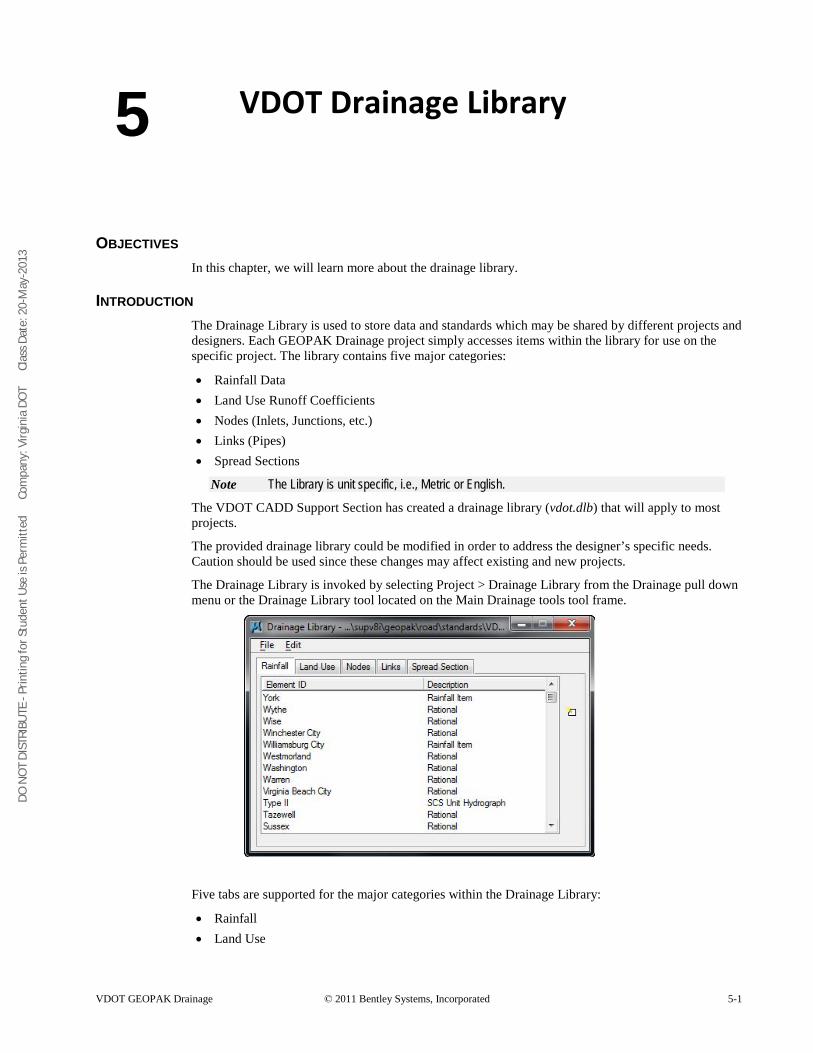
DO N
OT
DIST
RIBU
TE -
Prin
ting
for S
tude
nt U
se is
Per
mitt
ed
Co
mpa
ny: V
irgin
ia D
OT
C
lass
Dat
e: 2
0-M
ay-2
013
VDOT GEOPAK Drainage © 2011 Bentley Systems, Incorporated 5-1
VDOT Drainage Library
OBJECTIVES In this chapter, we will learn more about the drainage library.
INTRODUCTION The Drainage Library is used to store data and standards which may be shared by different projects and designers. Each GEOPAK Drainage project simply accesses items within the library for use on the specific project. The library contains five major categories:
• Rainfall Data • Land Use Runoff Coefficients • Nodes (Inlets, Junctions, etc.) • Links (Pipes) • Spread Sections
Note The Library is unit specific, i.e., Metric or English.
The VDOT CADD Support Section has created a drainage library (vdot.dlb) that will apply to most projects.
The provided drainage library could be modified in order to address the designer’s specific needs. Caution should be used since these changes may affect existing and new projects.
The Drainage Library is invoked by selecting Project > Drainage Library from the Drainage pull down menu or the Drainage Library tool located on the Main Drainage tools tool frame.
Five tabs are supported for the major categories within the Drainage Library:
• Rainfall • Land Use
5
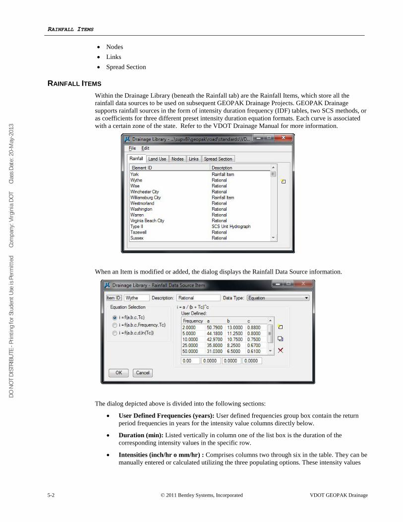
DO N
OT
DIST
RIBU
TE -
Prin
ting
for S
tude
nt U
se is
Per
mitt
ed
Co
mpa
ny: V
irgin
ia D
OT
C
lass
Dat
e: 2
0-M
ay-2
013
RAINFALL ITEMS
5-2 © 2011 Bentley Systems, Incorporated VDOT GEOPAK Drainage
• Nodes • Links • Spread Section
RAINFALL ITEMS Within the Drainage Library (beneath the Rainfall tab) are the Rainfall Items, which store all the rainfall data sources to be used on subsequent GEOPAK Drainage Projects. GEOPAK Drainage supports rainfall sources in the form of intensity duration frequency (IDF) tables, two SCS methods, or as coefficients for three different preset intensity duration equation formats. Each curve is associated with a certain zone of the state. Refer to the VDOT Drainage Manual for more information.
When an Item is modified or added, the dialog displays the Rainfall Data Source information.
The dialog depicted above is divided into the following sections:
• User Defined Frequencies (years): User defined frequencies group box contain the return period frequencies in years for the intensity value columns directly below.
• Duration (min): Listed vertically in column one of the list box is the duration of the corresponding intensity values in the specific row.
• Intensities (inch/hr o mm/hr) : Comprises columns two through six in the table. They can be manually entered or calculated utilizing the three populating options. These intensity values
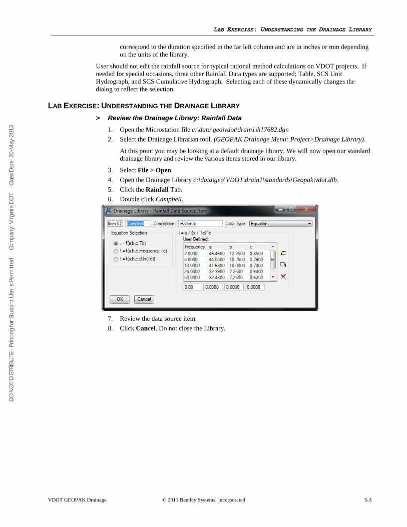
DO N
OT
DIST
RIBU
TE -
Prin
ting
for S
tude
nt U
se is
Per
mitt
ed
Co
mpa
ny: V
irgin
ia D
OT
C
lass
Dat
e: 2
0-M
ay-2
013
LAB EXERCISE: UNDERSTANDING THE DRAINAGE LIBRARY
VDOT GEOPAK Drainage © 2011 Bentley Systems, Incorporated 5-3
correspond to the duration specified in the far left column and are in inches or mm depending on the units of the library.
User should not edit the rainfall source for typical rational method calculations on VDOT projects. If needed for special occasions, three other Rainfall Data types are supported; Table, SCS Unit Hydrograph, and SCS Cumulative Hydrograph. Selecting each of these dynamically changes the dialog to reflect the selection.
LAB EXERCISE: UNDERSTANDING THE DRAINAGE LIBRARY > Review the Drainage Library: Rainfall Data
1. Open the Microstation file c:\data\geo\vdot\drain1\h17682.dgn 2. Select the Drainage Librarian tool. (GEOPAK Drainage Menu: Project>Drainage Library).
At this point you may be looking at a default drainage library. We will now open our standard drainage library and review the various items stored in our library.
3. Select File > Open. 4. Open the Drainage Library c:\data\geo\VDOT\drain1\standards\Geopak\vdot.dlb. 5. Click the Rainfall Tab. 6. Double click Campbell.
7. Review the data source item. 8. Click Cancel. Do not close the Library.
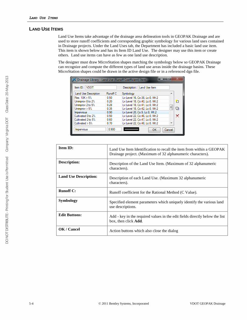
DO N
OT
DIST
RIBU
TE -
Prin
ting
for S
tude
nt U
se is
Per
mitt
ed
Co
mpa
ny: V
irgin
ia D
OT
C
lass
Dat
e: 2
0-M
ay-2
013
LAND USE ITEMS
5-4 © 2011 Bentley Systems, Incorporated VDOT GEOPAK Drainage
LAND USE ITEMS Land Use Items take advantage of the drainage area delineation tools in GEOPAK Drainage and are used to store runoff coefficients and corresponding graphic symbology for various land uses contained in Drainage projects. Under the Land Uses tab, the Department has included a basic land use item. This item is shown below and has its Item ID Land Use. The designer may use this item or create others. Land use items can have as few as one land use description.
The designer must draw MicroStation shapes matching the symbology below so GEOPAK Drainage can recognize and compute the different types of land use areas inside the drainage basins. These MicroStation shapes could be drawn in the active design file or in a referenced dgn file.
Item ID: Land Use Item Identification to recall the item from within a GEOPAK Drainage project. (Maximum of 32 alphanumeric characters).
Description: Description of the Land Use Item. (Maximum of 32 alphanumeric characters).
Land Use Description: Description of each Land Use. (Maximum 32 alphanumeric characters).
Runoff C: Runoff coefficient for the Rational Method (C Value).
Symbology Specified element parameters which uniquely identify the various land use descriptions.
Edit Buttons: Add - key in the required values in the edit fields directly below the list box, then click Add.
OK / Cancel Action buttons which also close the dialog
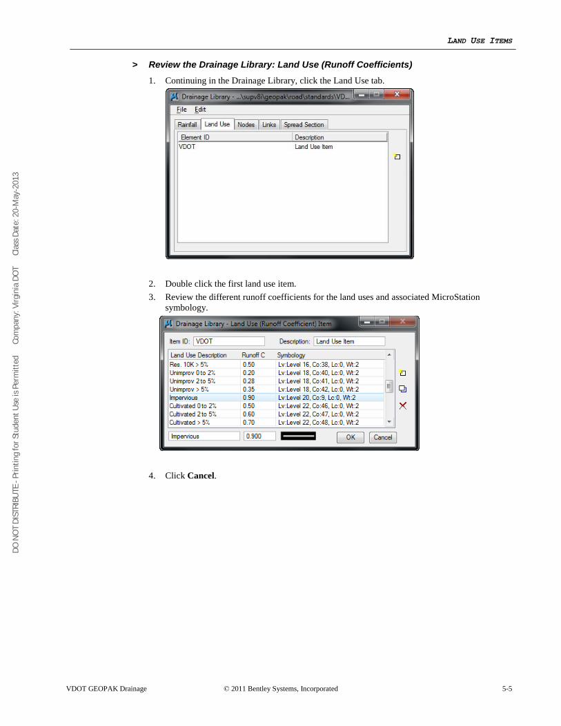
DO N
OT
DIST
RIBU
TE -
Prin
ting
for S
tude
nt U
se is
Per
mitt
ed
Co
mpa
ny: V
irgin
ia D
OT
C
lass
Dat
e: 2
0-M
ay-2
013
LAND USE ITEMS
VDOT GEOPAK Drainage © 2011 Bentley Systems, Incorporated 5-5
> Review the Drainage Library: Land Use (Runoff Coefficients) 1. Continuing in the Drainage Library, click the Land Use tab.
2. Double click the first land use item. 3. Review the different runoff coefficients for the land uses and associated MicroStation
symbology.
4. Click Cancel.
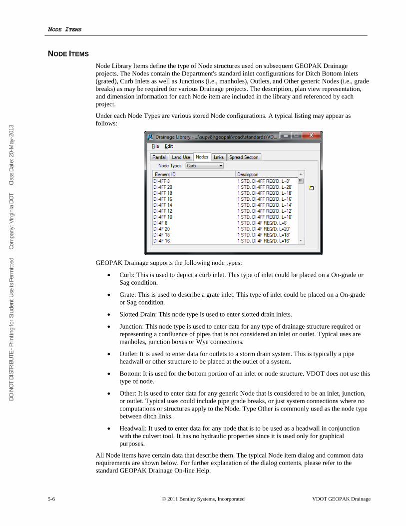
DO N
OT
DIST
RIBU
TE -
Prin
ting
for S
tude
nt U
se is
Per
mitt
ed
Co
mpa
ny: V
irgin
ia D
OT
C
lass
Dat
e: 2
0-M
ay-2
013
NODE ITEMS
5-6 © 2011 Bentley Systems, Incorporated VDOT GEOPAK Drainage
NODE ITEMS Node Library Items define the type of Node structures used on subsequent GEOPAK Drainage projects. The Nodes contain the Department's standard inlet configurations for Ditch Bottom Inlets (grated), Curb Inlets as well as Junctions (i.e., manholes), Outlets, and Other generic Nodes (i.e., grade breaks) as may be required for various Drainage projects. The description, plan view representation, and dimension information for each Node item are included in the library and referenced by each project.
Under each Node Types are various stored Node configurations. A typical listing may appear as follows:
GEOPAK Drainage supports the following node types:
• Curb: This is used to depict a curb inlet. This type of inlet could be placed on a On-grade or Sag condition.
• Grate: This is used to describe a grate inlet. This type of inlet could be placed on a On-grade or Sag condition.
• Slotted Drain: This node type is used to enter slotted drain inlets.
• Junction: This node type is used to enter data for any type of drainage structure required or representing a confluence of pipes that is not considered an inlet or outlet. Typical uses are manholes, junction boxes or Wye connections.
• Outlet: It is used to enter data for outlets to a storm drain system. This is typically a pipe headwall or other structure to be placed at the outlet of a system.
• Bottom: It is used for the bottom portion of an inlet or node structure. VDOT does not use this type of node.
• Other: It is used to enter data for any generic Node that is considered to be an inlet, junction, or outlet. Typical uses could include pipe grade breaks, or just system connections where no computations or structures apply to the Node. Type Other is commonly used as the node type between ditch links.
• Headwall: It used to enter data for any node that is to be used as a headwall in conjunction with the culvert tool. It has no hydraulic properties since it is used only for graphical purposes.
All Node items have certain data that describe them. The typical Node item dialog and common data requirements are shown below. For further explanation of the dialog contents, please refer to the standard GEOPAK Drainage On-line Help.
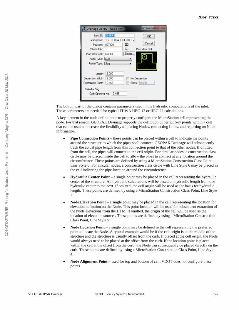
DO N
OT
DIST
RIBU
TE -
Prin
ting
for S
tude
nt U
se is
Per
mitt
ed
Co
mpa
ny: V
irgin
ia D
OT
C
lass
Dat
e: 2
0-M
ay-2
013
NODE ITEMS
VDOT GEOPAK Drainage © 2011 Bentley Systems, Incorporated 5-7
The bottom part of the dialog contains parameters used in the hydraulic computations of the inlet. These parameters are needed for typical FHWA HEC-12 or HEC-22 calculations.
A key element in the node definition is to properly configure the MicroStation cell representing the node. For that reason, GEOPAK Drainage supports the definition of certain key points within a cell that can be used to increase the flexibility of placing Nodes, connecting Links, and reporting on Node information.
• Pipe Connection Points – these points can be placed within a cell to indicate the points around the structure to which the pipes shall connect. GEOPAK Drainage will subsequently track the actual pipe length from this connection point to that of the other nodes. If omitted from the cell, the pipes will connect to the cell origin. For circular nodes, a construction class circle may be placed inside the cell to allow the pipes to connect at any location around the circumference. These points are defined by using a MicroStation Construction Class Point, Line Style 6. For circular nodes, a construction class circle with Line Style 6 may be placed in the cell indicating the pipe location around the circumference.
• Hydraulic Center Point – a single point may be placed in the cell representing the hydraulic center of the structure. All hydraulic calculations will be based on hydraulic length from one hydraulic center to the next. If omitted, the cell origin will be used as the basis for hydraulic length. These points are defined by using a MicroStation Construction Class Point, Line Style 7.
• Node Elevation Point – a single point may be placed in the cell representing the location for elevation definition on the Node. This point location will be used for subsequent extraction of the Node elevations from the DTM. If omitted, the origin of the cell will be used as the location of elevation sources. These points are defined by using a MicroStation Construction Class Point, Line Style 5.
• Node Location Point – a single point may be defined in the cell representing the preferred point to locate the Node. A typical example would be if the cell origin is in the middle of the structure and the structure is usually offset from the curb. If placed at the cell origin, the Node would always need to be placed at the offset from the curb. If the location point is placed within the cell at the offset from the curb, the Node can subsequently be placed directly on the curb. These points are defined by using a MicroStation Construction Class Point, Line Style 4.
• Node Alignment Point – used for top and bottom of cell. VDOT does not configure these points.
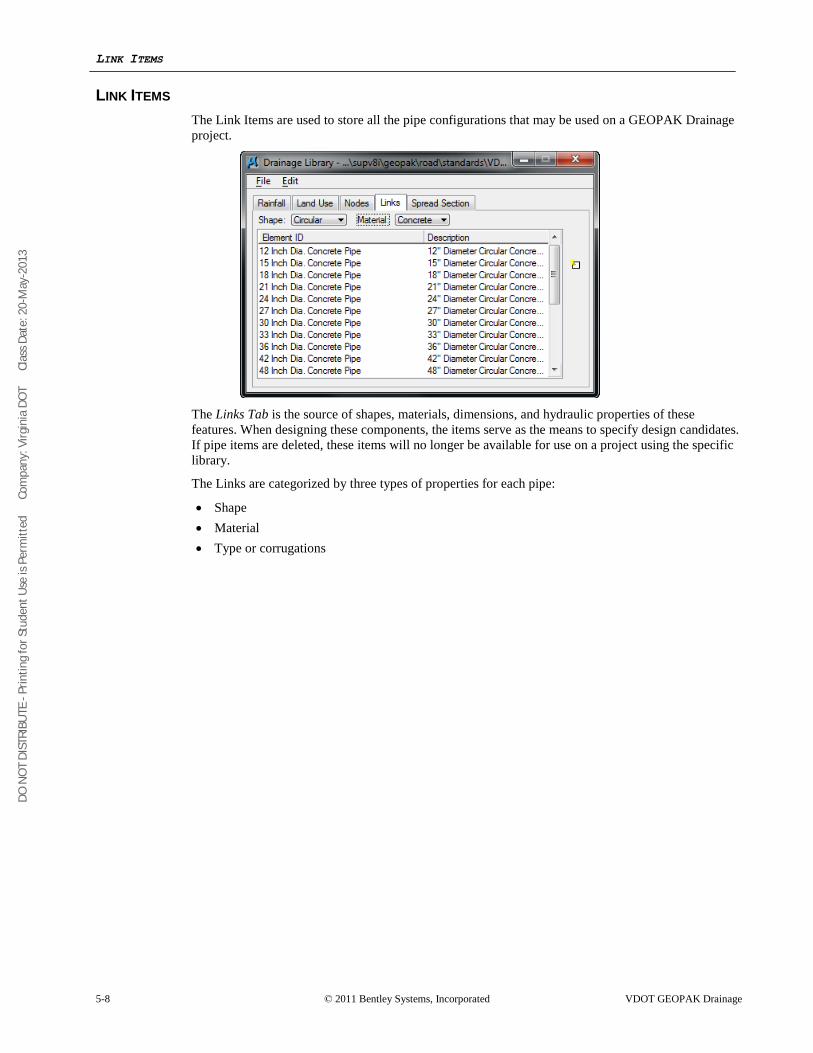
DO N
OT
DIST
RIBU
TE -
Prin
ting
for S
tude
nt U
se is
Per
mitt
ed
Co
mpa
ny: V
irgin
ia D
OT
C
lass
Dat
e: 2
0-M
ay-2
013
LINK ITEMS
5-8 © 2011 Bentley Systems, Incorporated VDOT GEOPAK Drainage
LINK ITEMS The Link Items are used to store all the pipe configurations that may be used on a GEOPAK Drainage project.
The Links Tab is the source of shapes, materials, dimensions, and hydraulic properties of these features. When designing these components, the items serve as the means to specify design candidates. If pipe items are deleted, these items will no longer be available for use on a project using the specific library.
The Links are categorized by three types of properties for each pipe:
• Shape • Material • Type or corrugations
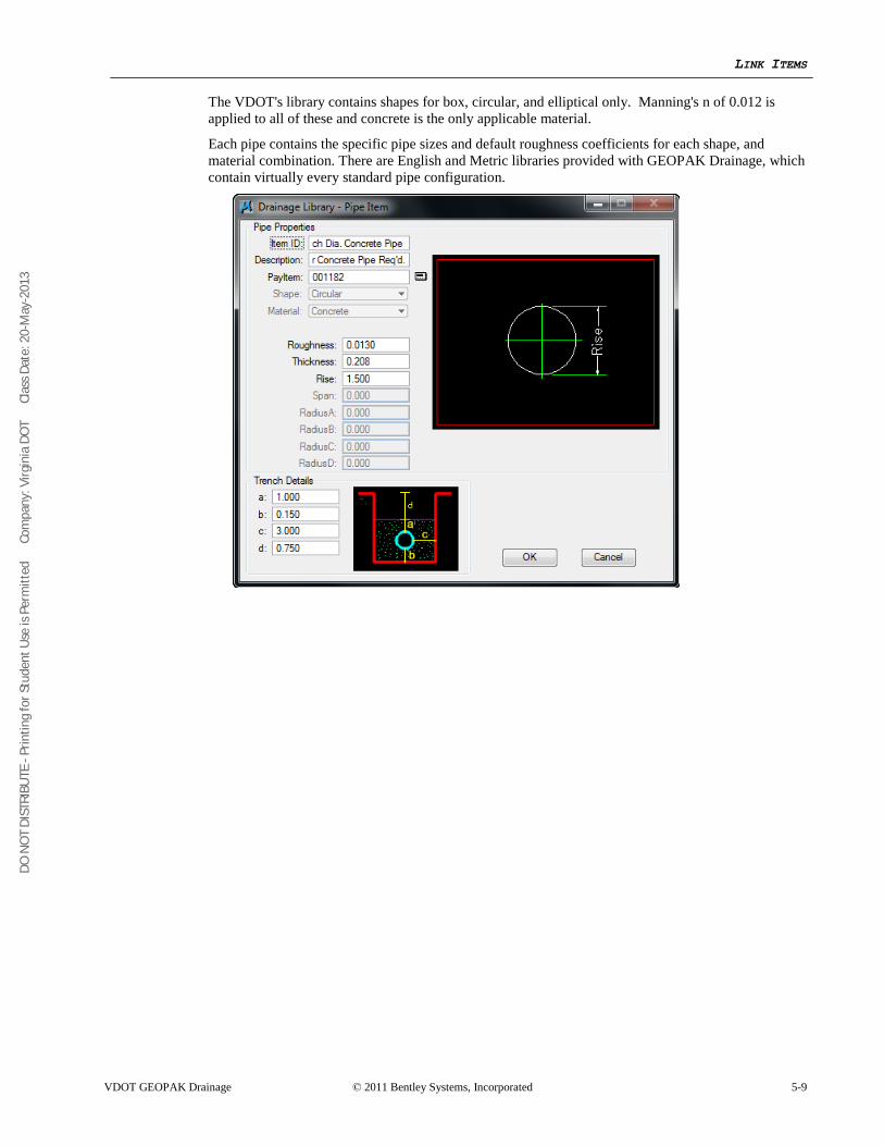
DO N
OT
DIST
RIBU
TE -
Prin
ting
for S
tude
nt U
se is
Per
mitt
ed
Co
mpa
ny: V
irgin
ia D
OT
C
lass
Dat
e: 2
0-M
ay-2
013
LINK ITEMS
VDOT GEOPAK Drainage © 2011 Bentley Systems, Incorporated 5-9
The VDOT's library contains shapes for box, circular, and elliptical only. Manning's n of 0.012 is applied to all of these and concrete is the only applicable material.
Each pipe contains the specific pipe sizes and default roughness coefficients for each shape, and material combination. There are English and Metric libraries provided with GEOPAK Drainage, which contain virtually every standard pipe configuration.
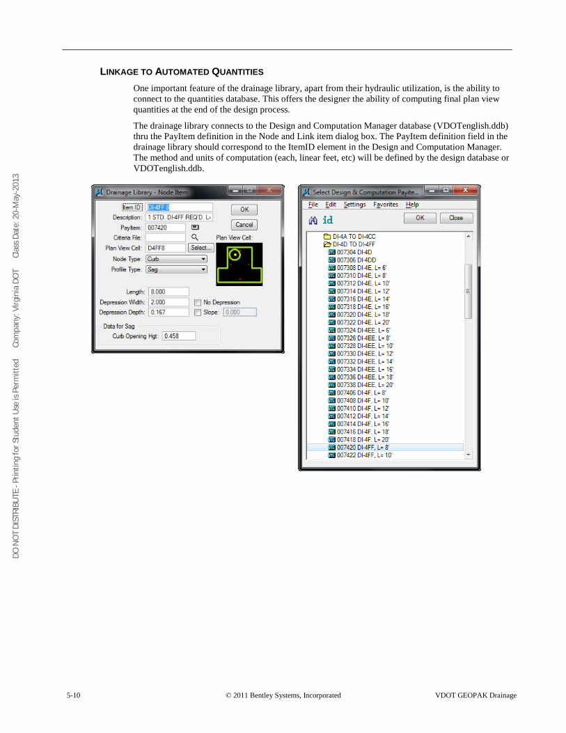
DO N
OT
DIST
RIBU
TE -
Prin
ting
for S
tude
nt U
se is
Per
mitt
ed
Co
mpa
ny: V
irgin
ia D
OT
C
lass
Dat
e: 2
0-M
ay-2
013
5-10 © 2011 Bentley Systems, Incorporated VDOT GEOPAK Drainage
LINKAGE TO AUTOMATED QUANTITIES One important feature of the drainage library, apart from their hydraulic utilization, is the ability to connect to the quantities database. This offers the designer the ability of computing final plan view quantities at the end of the design process.
The drainage library connects to the Design and Computation Manager database (VDOTenglish.ddb) thru the PayItem definition in the Node and Link item dialog box. The PayItem definition field in the drainage library should correspond to the ItemID element in the Design and Computation Manager. The method and units of computation (each, linear feet, etc) will be defined by the design database or VDOTenglish.ddb.
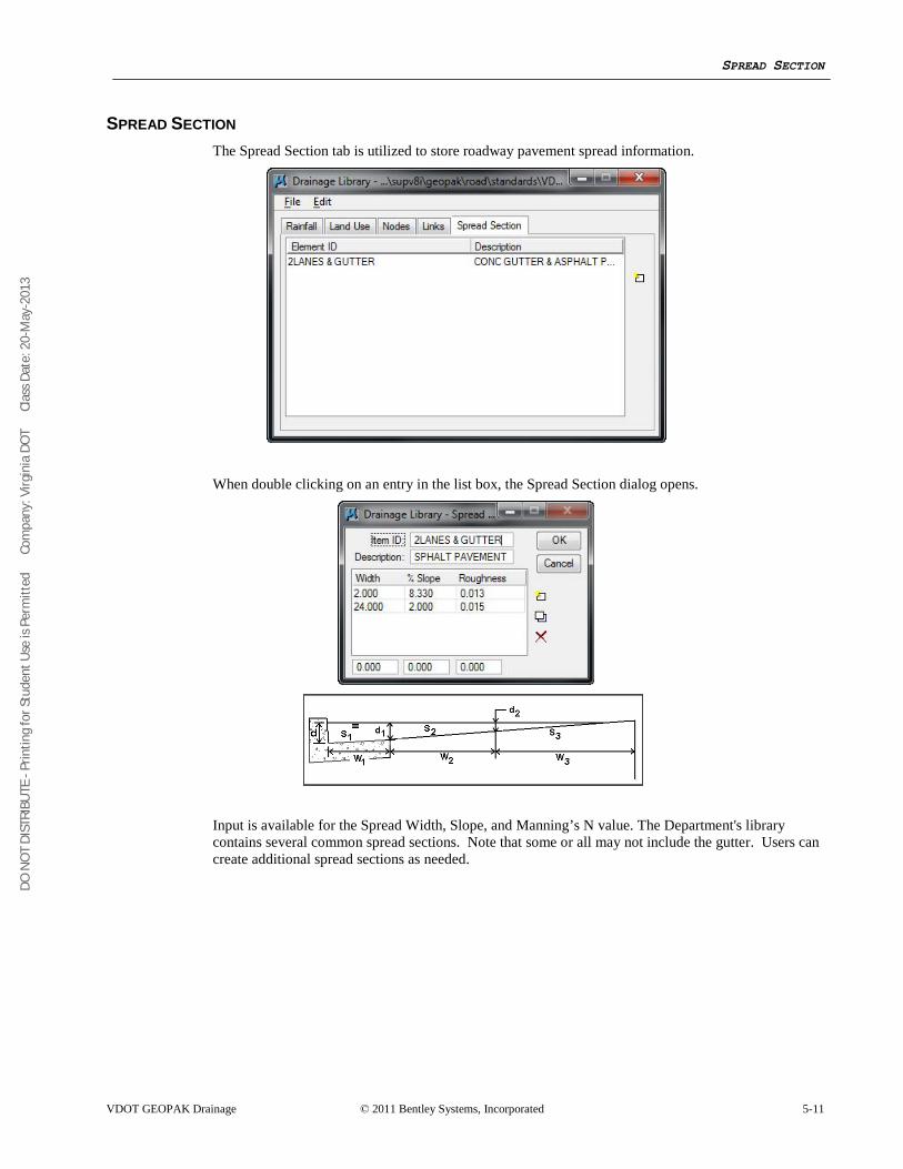
DO N
OT
DIST
RIBU
TE -
Prin
ting
for S
tude
nt U
se is
Per
mitt
ed
Co
mpa
ny: V
irgin
ia D
OT
C
lass
Dat
e: 2
0-M
ay-2
013
SPREAD SECTION
VDOT GEOPAK Drainage © 2011 Bentley Systems, Incorporated 5-11
SPREAD SECTION The Spread Section tab is utilized to store roadway pavement spread information.
When double clicking on an entry in the list box, the Spread Section dialog opens.
Input is available for the Spread Width, Slope, and Manning’s N value. The Department's library contains several common spread sections. Note that some or all may not include the gutter. Users can create additional spread sections as needed.
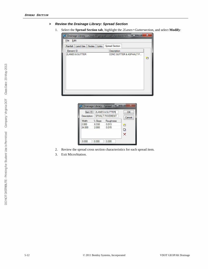
DO N
OT
DIST
RIBU
TE -
Prin
ting
for S
tude
nt U
se is
Per
mitt
ed
Co
mpa
ny: V
irgin
ia D
OT
C
lass
Dat
e: 2
0-M
ay-2
013
SPREAD SECTION
5-12 © 2011 Bentley Systems, Incorporated VDOT GEOPAK Drainage
> Review the Drainage Library: Spread Section 1. Select the Spread Section tab, highlight the 2Lanes+Guttersection, and select Modify:
2. Review the spread cross section characteristics for each spread item. 3. Exit MicroStation.
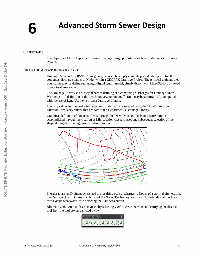
DO N
OT
DIST
RIBU
TE -
Prin
ting
for S
tude
nt U
se is
Per
mitt
ed
Co
mpa
ny: V
irgin
ia D
OT
C
lass
Dat
e: 2
0-M
ay-2
013
VDOT GEOPAK Drainage © 2011 Bentley Systems, Incorporated 6-1
Advanced Storm Sewer Design
OBJECTIVES The objective of this chapter is to review drainage design procedures on how to design a storm sewer system.
DRAINAGE AREAS: INTRODUCTION Drainage Areas in GEOPAK Drainage may be used to simply compute peak discharges or to attach computed discharge values to Nodes within a GEOPAK Drainage Project. The physical drainage area boundaries may be delineated using a digital terrain model, simply drawn with MicroStation, or keyed in as a total area value.
The Drainage Library is an integral part of defining and computing discharges for Drainage Areas. With graphical definition of the area boundary, runoff coefficients may be automatically computed with the use of Land Use Items from a Drainage Library.
Intensity values for the peak discharge computations are computed using the FDOT Intensity-Duration-Frequency curves that are part of the Department’s Drainage Library.
Graphical definition of Drainage Areas through the DTM Drainage Tools or MicroStation is accomplished through the creation of MicroStation closed shapes and subsequent selection of the shape during the Drainage Area creation process.
In order to assign Drainage Areas and the resulting peak discharges to Nodes of a storm drain network, the Drainage Area ID must match that of the Node. The best option to match the Node and the Area is thru Component>Node, then selecting the Edit Area button.
Alternately, the Area tools are invoked by selecting Tool Boxes > Area, then identifying the desired tool from the tool box as depicted below.
6
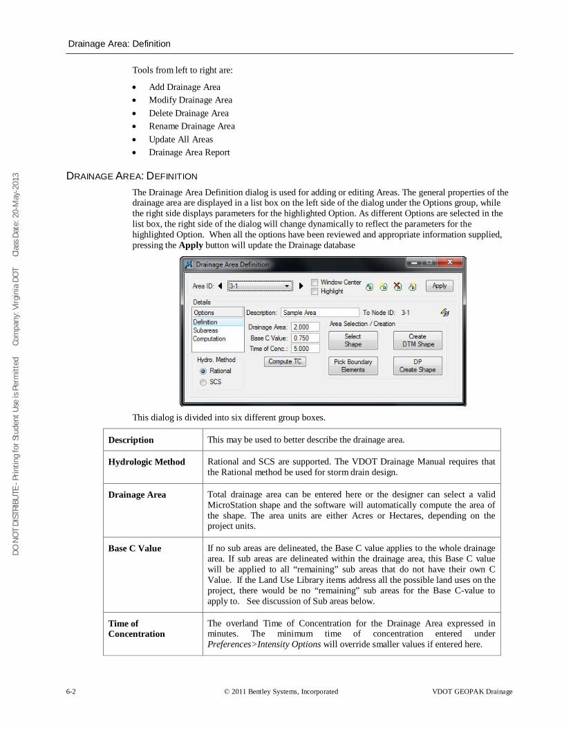
DO N
OT
DIST
RIBU
TE -
Prin
ting
for S
tude
nt U
se is
Per
mitt
ed
Co
mpa
ny: V
irgin
ia D
OT
C
lass
Dat
e: 2
0-M
ay-2
013
Drainage Area: Definition
6-2 © 2011 Bentley Systems, Incorporated VDOT GEOPAK Drainage
Tools from left to right are:
• Add Drainage Area • Modify Drainage Area • Delete Drainage Area • Rename Drainage Area • Update All Areas • Drainage Area Report
DRAINAGE AREA: DEFINITION The Drainage Area Definition dialog is used for adding or editing Areas. The general properties of the drainage area are displayed in a list box on the left side of the dialog under the Options group, while the right side displays parameters for the highlighted Option. As different Options are selected in the list box, the right side of the dialog will change dynamically to reflect the parameters for the highlighted Option. When all the options have been reviewed and appropriate information supplied, pressing the Apply button will update the Drainage database
This dialog is divided into six different group boxes.
Description This may be used to better describe the drainage area.
Hydrologic Method Rational and SCS are supported. The VDOT Drainage Manual requires that the Rational method be used for storm drain design.
Drainage Area Total drainage area can be entered here or the designer can select a valid MicroStation shape and the software will automatically compute the area of the shape. The area units are either Acres or Hectares, depending on the project units.
Base C Value If no sub areas are delineated, the Base C value applies to the whole drainage area. If sub areas are delineated within the drainage area, this Base C value will be applied to all “remaining” sub areas that do not have their own C Value. If the Land Use Library items address all the possible land uses on the project, there would be no “remaining” sub areas for the Base C-value to apply to. See discussion of Sub areas below.
Time of Concentration
The overland Time of Concentration for the Drainage Area expressed in minutes. The minimum time of concentration entered under Preferences>Intensity Options will override smaller values if entered here.
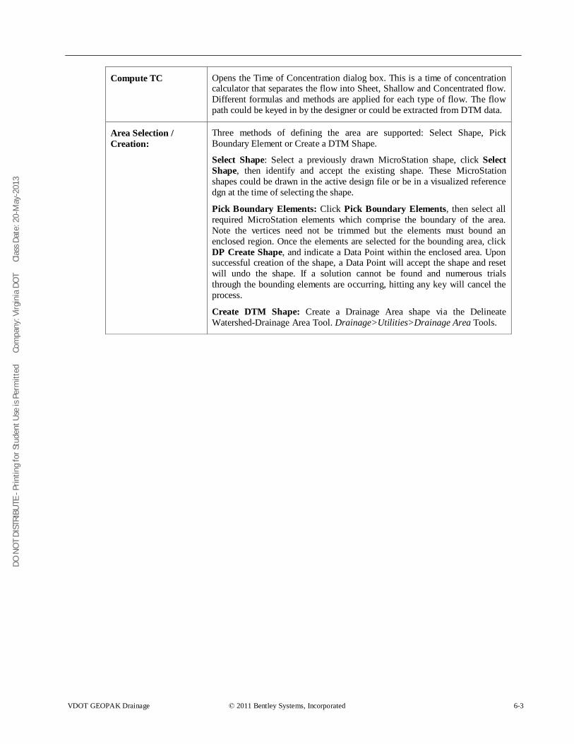
DO N
OT
DIST
RIBU
TE -
Prin
ting
for S
tude
nt U
se is
Per
mitt
ed
Co
mpa
ny: V
irgin
ia D
OT
C
lass
Dat
e: 2
0-M
ay-2
013
VDOT GEOPAK Drainage © 2011 Bentley Systems, Incorporated 6-3
Compute TC Opens the Time of Concentration dialog box. This is a time of concentration calculator that separates the flow into Sheet, Shallow and Concentrated flow. Different formulas and methods are applied for each type of flow. The flow path could be keyed in by the designer or could be extracted from DTM data.
Area Selection / Creation:
Three methods of defining the area are supported: Select Shape, Pick Boundary Element or Create a DTM Shape.
Select Shape: Select a previously drawn MicroStation shape, click Select Shape, then identify and accept the existing shape. These MicroStation shapes could be drawn in the active design file or be in a visualized reference dgn at the time of selecting the shape.
Pick Boundary Elements: Click Pick Boundary Elements, then select all required MicroStation elements which comprise the boundary of the area. Note the vertices need not be trimmed but the elements must bound an enclosed region. Once the elements are selected for the bounding area, click DP Create Shape, and indicate a Data Point within the enclosed area. Upon successful creation of the shape, a Data Point will accept the shape and reset will undo the shape. If a solution cannot be found and numerous trials through the bounding elements are occurring, hitting any key will cancel the process.
Create DTM Shape: Create a Drainage Area shape via the Delineate Watershed-Drainage Area Tool. Drainage>Utilities>Drainage Area Tools.
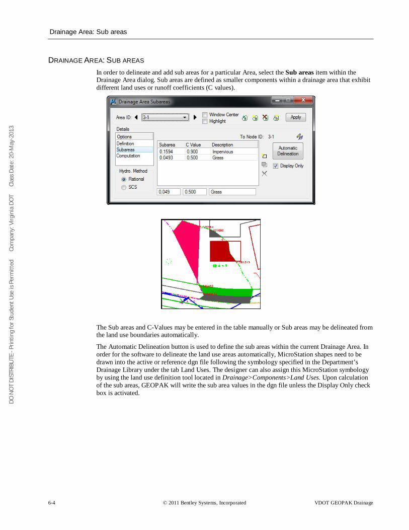
DO N
OT
DIST
RIBU
TE -
Prin
ting
for S
tude
nt U
se is
Per
mitt
ed
Co
mpa
ny: V
irgin
ia D
OT
C
lass
Dat
e: 2
0-M
ay-2
013
Drainage Area: Sub areas
6-4 © 2011 Bentley Systems, Incorporated VDOT GEOPAK Drainage
DRAINAGE AREA: SUB AREAS In order to delineate and add sub areas for a particular Area, select the Sub areas item within the Drainage Area dialog. Sub areas are defined as smaller components within a drainage area that exhibit different land uses or runoff coefficients (C values).
The Sub areas and C-Values may be entered in the table manually or Sub areas may be delineated from the land use boundaries automatically.
The Automatic Delineation button is used to define the sub areas within the current Drainage Area. In order for the software to delineate the land use areas automatically, MicroStation shapes need to be drawn into the active or reference dgn file following the symbology specified in the Department’s Drainage Library under the tab Land Uses. The designer can also assign this MicroStation symbology by using the land use definition tool located in Drainage>Components>Land Uses. Upon calculation of the sub areas, GEOPAK will write the sub area values in the dgn file unless the Display Only check box is activated.
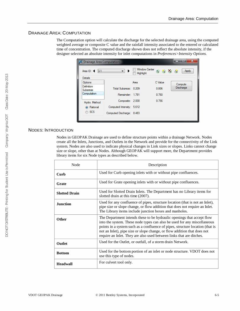
DO N
OT
DIST
RIBU
TE -
Prin
ting
for S
tude
nt U
se is
Per
mitt
ed
Co
mpa
ny: V
irgin
ia D
OT
C
lass
Dat
e: 2
0-M
ay-2
013
Drainage Area: Computation
VDOT GEOPAK Drainage © 2011 Bentley Systems, Incorporated 6-5
DRAINAGE AREA: COMPUTATION The Computation option will calculate the discharge for the selected drainage area, using the computed weighted average or composite C value and the rainfall intensity associated to the entered or calculated time of concentration. The computed discharge shown does not reflect the absolute intensity, if the designer selected an absolute intensity for inlet computations in Preferences>Intensity Options.
NODES: INTRODUCTION Nodes in GEOPAK Drainage are used to define structure points within a drainage Network. Nodes create all the Inlets, Junctions, and Outlets in the Network and provide for the connectivity of the Link system. Nodes are also used to indicate physical changes in Link sizes or slopes. Links cannot change size or slope, other than at Nodes. Although GEOPAK will support more, the Department provides library items for six Node types as described below.
Node Description
Curb Used for Curb opening inlets with or without pipe confluences.
Grate Used for Grate opening inlets with or without pipe confluences.
Slotted Drain Used for Slotted Drain Inlets. The Department has no Library items for slotted drain at this time (2007).
Junction Used for any confluence of pipes, structure location (that is not an Inlet), pipe size or slope change, or flow addition that does not require an Inlet. The Library items include junction boxes and manholes.
Other The Department intends these to be hydraulic openings that accept flow into the system. These node types can also be used for any miscellaneous points in a system such as a confluence of pipes, structure location (that is not an Inlet), pipe size or slope change, or flow addition that does not require an Inlet. They are also used between links that are ditches.
Outlet Used for the Outlet, or outfall, of a storm drain Network.
Bottom Used for the bottom portion of an inlet or node structure. VDOT does not use this type of nodes.
Headwall For culvert tool only.
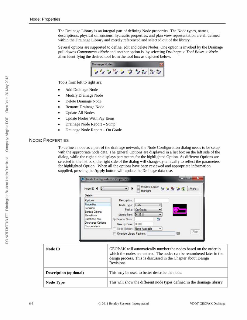
DO N
OT
DIST
RIBU
TE -
Prin
ting
for S
tude
nt U
se is
Per
mitt
ed
Co
mpa
ny: V
irgin
ia D
OT
C
lass
Dat
e: 2
0-M
ay-2
013
Node: Properties
6-6 © 2011 Bentley Systems, Incorporated VDOT GEOPAK Drainage
The Drainage Library is an integral part of defining Node properties. The Node types, names, descriptions, physical dimensions, hydraulic properties, and plan view representation are all defined within the Drainage Library and merely referenced and selected out of the library.
Several options are supported to define, edit and delete Nodes. One option is invoked by the Drainage pull downs Components>Node and another option is by selecting Drainage > Tool Boxes > Node ,then identifying the desired tool from the tool box as depicted below.
Tools from left to right are:
• Add Drainage Node • Modify Drainage Node • Delete Drainage Node • Rename Drainage Node • Update All Nodes • Update Nodes With Pay Items • Drainage Node Report – Sump • Drainage Node Report – On Grade
NODE: PROPERTIES To define a node as a part of the drainage network, the Node Configuration dialog needs to be setup with the appropriate node data. The general Options are displayed in a list box on the left side of the dialog, while the right side displays parameters for the highlighted Option. As different Options are selected in the list box, the right side of the dialog will change dynamically to reflect the parameters for highlighted Option. When all the options have been reviewed and appropriate information supplied, pressing the Apply button will update the Drainage database.
Node ID GEOPAK will automatically number the nodes based on the order in which the nodes are entered. The nodes can be renumbered later in the design process. This is discussed in the Chapter about Design Revisions.
Description (optional) This may be used to better describe the node.
Node Type This will show the different node types defined in the drainage library.
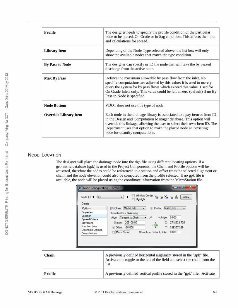
DO N
OT
DIST
RIBU
TE -
Prin
ting
for S
tude
nt U
se is
Per
mitt
ed
Co
mpa
ny: V
irgin
ia D
OT
C
lass
Dat
e: 2
0-M
ay-2
013
VDOT GEOPAK Drainage © 2011 Bentley Systems, Incorporated 6-7
Profile The designer needs to specify the profile condition of the particular node to be placed. On Grade or in Sag condition. This affects the input and calculations for spread.
Library Item Depending of the Node Type selected above, the list box will only show the available nodes that match the type condition.
By Pass to Node The designer can specify or ID the node that will take the by passed discharge from the active node.
Max By Pass Defines the maximum allowable by pass flow from the inlet. No specific computations are adjusted by this value; it is used to merely query the system for by pass flows which exceed this value. Used for On Grade Inlets only. This value could be left at zero (default) if no By Pass to Node is specified.
Node Bottom VDOT does not use this type of node.
Override Library Item Each node in the drainage library is associated to a pay item or Item ID in the Design and Computation Manager database. This option will override this linkage, allowing the user to select their own Item ID. The Department uses that option to make the placed node an “existing” node for quantity computations.
NODE: LOCATION The designer will place the drainage node into the dgn file using different locating options. If a geometric database (gpk) is used in the Project Components, the Chain and Profile options will be activated, therefore the nodes could be referenced to a station and offset from the selected alignment or chain, and the node elevation could also be computed from the profile selected. If no gpk file is available, the node will be placed using the coordinate information from the MicroStation file.
Chain A previously defined horizontal alignment stored in the "gpk" file. Activate the toggle to the left of the field and select the chain from the list
Profile A previously defined vertical profile stored in the "gpk" file. Activate
DO N
OT
DIST
RIBU
TE -
Prin
ting
for S
tude
nt U
se is
Per
mitt
ed
Co
mpa
ny: V
irgin
ia D
OT
C
lass
Dat
e: 2
0-M
ay-2
013
6-8 © 2011 Bentley Systems, Incorporated VDOT GEOPAK Drainage
the toggle to the left of the field and select the desired profile from the list.
Align: At Point When this option is utilized, the node is placed at the active angle in the MicroStation file at the current or dynamic Node coordinates.
Align: Tangent to Chain When this option is utilized, the node is dynamically moved along the Chain, and is rotated maintaining tangency to the chain. The designer can enter the station location or place the node dynamically.
Align: Tangent on Element When this option is utilized, the ID button to the right of the option is activated and the designer is prompted to identify and accept a MicroStation element. The Node is placed tangent to and on the identified element projected from the current or dynamic Node coordinates. The designer can enter the station location or place the node dynamically.
Align: Tangent to Element When this option is utilized, the ID button to the right of the option is activated and the designer is prompted to identify and accept a MicroStation element. The Node is placed tangent to the identified element at the current or dynamic Node coordinates
Angle An optional angle rotation could be applied to the node. A 180-degree angle is often needed to properly align the throat of curb inlets and is sometimes used in conjunction with the Mirror Node toggle.
Station and Offset Nodes may be located by entering the station and offset in reference to the selected chain. If "Tangent on Element" is used, the offset is computed.
Mirror Node When activated, the node cell is mirrored, in order that the same cell can be utilized to accommodate flow coming from either direction.
Offset from Gutter to Inlet Inlet hydraulic equations assume the Inlet is at the edge of the computed spread (i.e. the Curb). If the Inlet is offset from the Curb, the discharge in the spread section will bypass the Inlet. This value, expressed in terms of feet or meters, is used to compute this bypass and adjust the actual flow to the Inlet. This may be used, for example, when a Grate Inlet is actually set some distance away from the curb of the road.
Therefore any flow calculated in that segment will not be added to the inlet and it will bypass to the next assigned one.
This value should remain zero for standard VDOT inlet applications.
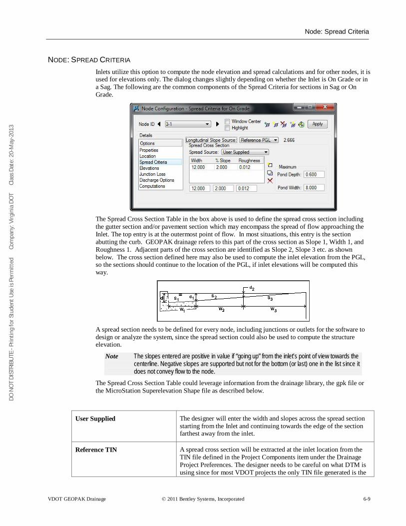
DO N
OT
DIST
RIBU
TE -
Prin
ting
for S
tude
nt U
se is
Per
mitt
ed
Co
mpa
ny: V
irgin
ia D
OT
C
lass
Dat
e: 2
0-M
ay-2
013
Node: Spread Criteria
VDOT GEOPAK Drainage © 2011 Bentley Systems, Incorporated 6-9
NODE: SPREAD CRITERIA Inlets utilize this option to compute the node elevation and spread calculations and for other nodes, it is used for elevations only. The dialog changes slightly depending on whether the Inlet is On Grade or in a Sag. The following are the common components of the Spread Criteria for sections in Sag or On Grade.
The Spread Cross Section Table in the box above is used to define the spread cross section including the gutter section and/or pavement section which may encompass the spread of flow approaching the Inlet. The top entry is at the outermost point of flow. In most situations, this entry is the section abutting the curb. GEOPAK drainage refers to this part of the cross section as Slope 1, Width 1, and Roughness 1. Adjacent parts of the cross section are identified as Slope 2, Slope 3 etc. as shown below. The cross section defined here may also be used to compute the inlet elevation from the PGL, so the sections should continue to the location of the PGL, if inlet elevations will be computed this way.
A spread section needs to be defined for every node, including junctions or outlets for the software to design or analyze the system, since the spread section could also be used to compute the structure elevation.
Note The slopes entered are positive in value if “going up” from the inlet’s point of view towards the centerline. Negative slopes are supported but not for the bottom (or last) one in the list since it does not convey flow to the node.
The Spread Cross Section Table could leverage information from the drainage library, the gpk file or the MicroStation Superelevation Shape file as described below.
User Supplied The designer will enter the width and slopes across the spread section starting from the Inlet and continuing towards the edge of the section farthest away from the inlet.
Reference TIN A spread cross section will be extracted at the inlet location from the TIN file defined in the Project Components item under the Drainage Project Preferences. The designer needs to be careful on what DTM is using since for most VDOT projects the only TIN file generated is the
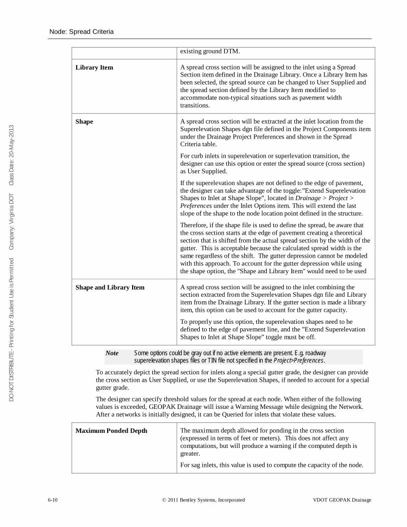
DO N
OT
DIST
RIBU
TE -
Prin
ting
for S
tude
nt U
se is
Per
mitt
ed
Co
mpa
ny: V
irgin
ia D
OT
C
lass
Dat
e: 2
0-M
ay-2
013
Node: Spread Criteria
6-10 © 2011 Bentley Systems, Incorporated VDOT GEOPAK Drainage
existing ground DTM.
Library Item A spread cross section will be assigned to the inlet using a Spread Section item defined in the Drainage Library. Once a Library Item has been selected, the spread source can be changed to User Supplied and the spread section defined by the Library Item modified to accommodate non-typical situations such as pavement width transitions.
Shape A spread cross section will be extracted at the inlet location from the Superelevation Shapes dgn file defined in the Project Components item under the Drainage Project Preferences and shown in the Spread Criteria table.
For curb inlets in superelevation or superlevation transition, the designer can use this option or enter the spread source (cross section) as User Supplied.
If the superelevation shapes are not defined to the edge of pavement, the designer can take advantage of the toggle:”Extend Superelevation Shapes to Inlet at Shape Slope”, located in Drainage > Project > Preferences under the Inlet Options item. This will extend the last slope of the shape to the node location point defined in the structure.
Therefore, if the shape file is used to define the spread, be aware that the cross section starts at the edge of pavement creating a theoretical section that is shifted from the actual spread section by the width of the gutter. This is acceptable because the calculated spread width is the same regardless of the shift. The gutter depression cannot be modeled with this approach. To account for the gutter depression while using the shape option, the "Shape and Library Item" would need to be used
Shape and Library Item A spread cross section will be assigned to the inlet combining the section extracted from the Superelevation Shapes dgn file and Library item from the Drainage Library. If the gutter section is made a library item, this option can be used to account for the gutter capacity.
To properly use this option, the superelevation shapes need to be defined to the edge of pavement line, and the ”Extend Superelevation Shapes to Inlet at Shape Slope” toggle must be off.
Note Some options could be gray out if no active elements are present. E.g. roadway superelevation shapes files or TIN file not specified in the Project>Preferences.
To accurately depict the spread section for inlets along a special gutter grade, the designer can provide the cross section as User Supplied, or use the Superelevation Shapes, if needed to account for a special gutter grade.
The designer can specify threshold values for the spread at each node. When either of the following values is exceeded, GEOPAK Drainage will issue a Warning Message while designing the Network. After a networks is initially designed, it can be Queried for inlets that violate these values.
Maximum Ponded Depth The maximum depth allowed for ponding in the cross section (expressed in terms of feet or meters). This does not affect any computations, but will produce a warning if the computed depth is greater.
For sag inlets, this value is used to compute the capacity of the node.
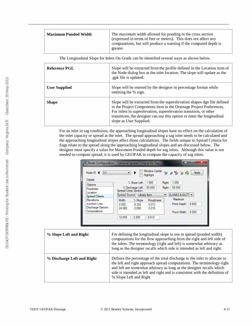
DO N
OT
DIST
RIBU
TE -
Prin
ting
for S
tude
nt U
se is
Per
mitt
ed
Co
mpa
ny: V
irgin
ia D
OT
C
lass
Dat
e: 2
0-M
ay-2
013
VDOT GEOPAK Drainage © 2011 Bentley Systems, Incorporated 6-11
Maximum Ponded Width The maximum width allowed for ponding in the cross section (expressed in terms of feet or meters). This does not affect any computations, but will produce a warning if the computed depth is greater.
The Longitudinal Slope for Inlets On Grade can be identified several ways as shown below.
Reference PGL Slope will be extracted from the profile defined in the Location item of the Node dialog box at the inlet location. The slope will update as the .gpk file is updated.
User Supplied Slope will be entered by the designer in percentage format while omitting the % sign.
Shape Slope will be extracted from the superelevation shapes dgn file defined in the Project Components item in the Drainage Project Preferences. For inlets in superelevation, superelevation transition, or other transitions, the designer can use this option or enter the longitudinal slope as User Supplied.
For an inlet in sag conditions, the approaching longitudinal slopes have no effect on the calculation of the inlet capacity or spread at the inlet. The spread approaching a sag inlet needs to be calculated and the approaching longitudinal slopes affect those calculations. The fields unique to Spread Criteria for Sags relate to the spread along the approaching longitudinal slopes and are discussed below. The designer must specify a value for Maximum Ponded depth for sag inlets. Although this value is not needed to compute spread, it is used by GEOPAK to compute the capacity of sag inlets.
% Slope Left and Right For defining the longitudinal slope to use in spread (ponded width) computations for the flow approaching from the right and left side of the inlets. The terminology (right and left) is somewhat arbitrary as long as the designer recalls which side is intended as left and right.
% Discharge Left and Right Defines the percentage of the total discharge to the inlet to allocate to the left and right approach spread computations. The terminology right and left are somewhat arbitrary as long as the designer recalls which side is intended as left and right and is consistent with the definition of % Slope Left and Right
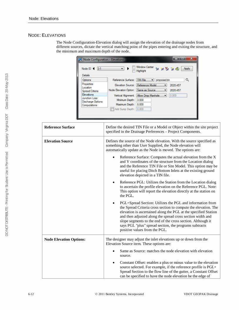
DO N
OT
DIST
RIBU
TE -
Prin
ting
for S
tude
nt U
se is
Per
mitt
ed
Co
mpa
ny: V
irgin
ia D
OT
C
lass
Dat
e: 2
0-M
ay-2
013
Node: Elevations
6-12 © 2011 Bentley Systems, Incorporated VDOT GEOPAK Drainage
NODE: ELEVATIONS The Node Configuration-Elevation dialog will assign the elevation of the drainage nodes from different sources, dictate the vertical matching point of the pipes entering and exiting the structure, and the minimum and maximum depth of the node.
Reference Surface Define the desired TIN File or a Model or Object within the site project specified in the Drainage Preferences – Project Components.
Elevation Source Defines the source of the Node elevation. With the source specified as something other than User Supplied, the Node elevation will automatically update as the Node is moved. The options are:
• Reference Surface: Computes the actual elevation from the X and Y coordinates of the structure from the Location dialog and the Reference TIN File or Site Model. This option may be useful for placing Ditch Bottom Inlets at the existing ground elevation depicted in a TIN file.
• Reference PGL: Utilizes the Station from the Location dialog to ascertain the profile elevation on the Reference PGL. Note: This option will report the elevation directly at the station on the PGL.
• PGL+Spread Section: Utilizes the PGL and information from the Spread Criteria cross section to compute the elevation. The elevation is ascertained along the PGL at the specified Station and then adjusted along the spread cross section width and slope segments to the end of the cross section. Although it says PGL "plus" spread section, the programs subtracts positive values from the PGL.
Node Elevation Options: The designer may adjust the inlet elevations up or down from the Elevation Source item. These options are:
• Same as Source: matches the node elevation with elevation source.
• Constant Offset: enables a plus or minus value to the elevation source selected. For example, if the reference profile is PGL+ Spread Section to the flow line of the gutter, a Constant Offset can be specified to have the node elevation be the edge of
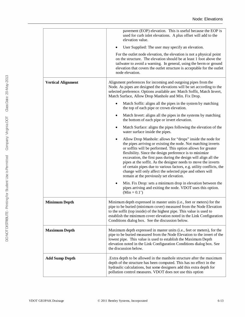
DO N
OT
DIST
RIBU
TE -
Prin
ting
for S
tude
nt U
se is
Per
mitt
ed
Co
mpa
ny: V
irgin
ia D
OT
C
lass
Dat
e: 2
0-M
ay-2
013
Node: Elevations
VDOT GEOPAK Drainage © 2011 Bentley Systems, Incorporated 6-13
pavement (EOP) elevation. This is useful because the EOP is used for curb inlet elevations. A plus offset will add to the elevation value.
• User Supplied: The user may specify an elevation.
For the outlet node elevation, the elevation is not a physical point on the structure. The elevation should be at least 1 foot above the tailwater to avoid a warning. In general, using the berm or ground elevation that covers the outlet structure is acceptable for the outlet node elevation.
Vertical Alignment Alignment preferences for incoming and outgoing pipes from the Node. As pipes are designed the elevations will be set according to the selected preference. Options available are: Match Soffit, Match Invert, Match Surface, Allow Drop Manhole and Min. Fix Drop.
• Match Soffit: aligns all the pipes in the system by matching the top of each pipe or crown elevation.
• Match Invert: aligns all the pipes in the systems by matching the bottom of each pipe or invert elevation.
• Match Surface: aligns the pipes following the elevation of the water surface inside the pipes.
• Allow Drop Manhole: allows for “drops” inside the node for the pipes arriving or existing the node. Not matching inverts or soffits will be performed. This option allows for greater flexibility. Since the design preference is to minimize excavation, the first pass during the design will align all the pipes at the soffit. As the designer needs to move the inverts of certain pipes due to various factors, e.g. utility conflicts, the change will only affect the selected pipe and others will remain at the previously set elevation.
• Min. Fix Drop: sets a minimum drop in elevation between the pipes arriving and exiting the node. VDOT uses this option. (Min = 0.1’)
Minimum Depth Minimum depth expressed in master units (i.e., feet or meters) for the pipe to be buried (minimum cover) measured from the Node Elevation to the soffit (top inside) of the highest pipe. This value is used to establish the minimum cover elevation noted in the Link Configuration Conditions dialog box. See the discussion below.
Maximum Depth Maximum depth expressed in master units (i.e., feet or meters), for the pipe to be buried measured from the Node Elevation to the invert of the lowest pipe. This value is used to establish the Maximum Depth elevation noted in the Link Configuration Conditions dialog box. See the discussion below.
Add Sump Depth .Extra depth to be allowed in the manhole structure after the maximum depth of the structure has been computed. This has no effect in the hydraulic calculations, but some designers add this extra depth for pollution control measures. VDOT does not use this option
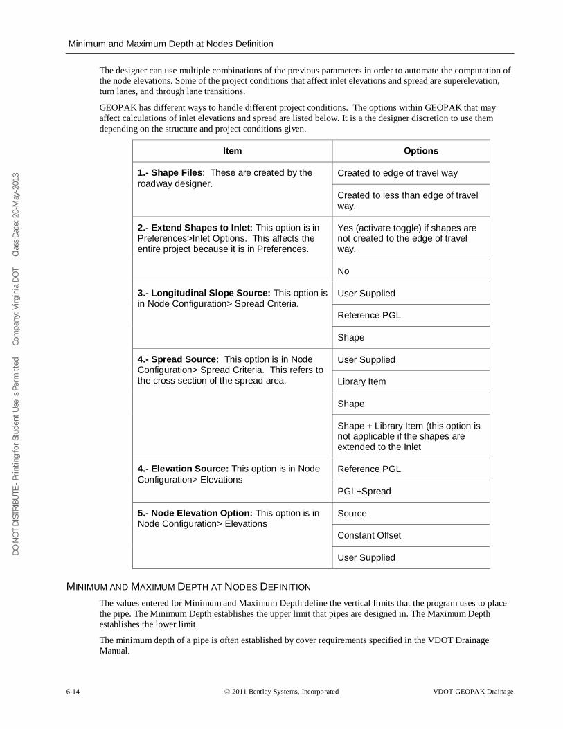
DO N
OT
DIST
RIBU
TE -
Prin
ting
for S
tude
nt U
se is
Per
mitt
ed
Co
mpa
ny: V
irgin
ia D
OT
C
lass
Dat
e: 2
0-M
ay-2
013
Minimum and Maximum Depth at Nodes Definition
6-14 © 2011 Bentley Systems, Incorporated VDOT GEOPAK Drainage
The designer can use multiple combinations of the previous parameters in order to automate the computation of the node elevations. Some of the project conditions that affect inlet elevations and spread are superelevation, turn lanes, and through lane transitions.
GEOPAK has different ways to handle different project conditions. The options within GEOPAK that may affect calculations of inlet elevations and spread are listed below. It is a the designer discretion to use them depending on the structure and project conditions given.
Item Options
1.- Shape Files: These are created by the roadway designer.
Created to edge of travel way
Created to less than edge of travel way.
2.- Extend Shapes to Inlet: This option is in Preferences>Inlet Options. This affects the entire project because it is in Preferences.
Yes (activate toggle) if shapes are not created to the edge of travel way.
No
3.- Longitudinal Slope Source: This option is in Node Configuration> Spread Criteria.
User Supplied
Reference PGL
Shape
4.- Spread Source: This option is in Node Configuration> Spread Criteria. This refers to the cross section of the spread area.
User Supplied
Library Item
Shape
Shape + Library Item (this option is not applicable if the shapes are extended to the Inlet
4.- Elevation Source: This option is in Node Configuration> Elevations
Reference PGL
PGL+Spread
5.- Node Elevation Option: This option is in Node Configuration> Elevations
Source
Constant Offset
User Supplied
MINIMUM AND MAXIMUM DEPTH AT NODES DEFINITION The values entered for Minimum and Maximum Depth define the vertical limits that the program uses to place the pipe. The Minimum Depth establishes the upper limit that pipes are designed in. The Maximum Depth establishes the lower limit.
The minimum depth of a pipe is often established by cover requirements specified in the VDOT Drainage Manual.
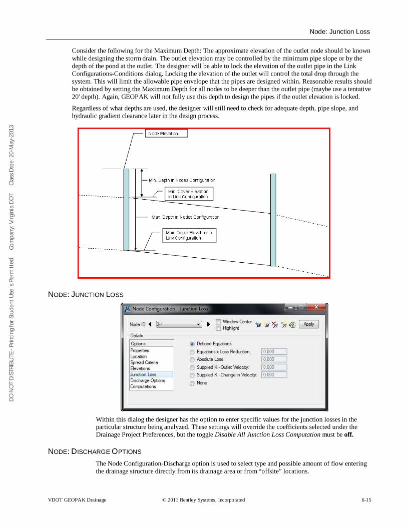
DO N
OT
DIST
RIBU
TE -
Prin
ting
for S
tude
nt U
se is
Per
mitt
ed
Co
mpa
ny: V
irgin
ia D
OT
C
lass
Dat
e: 2
0-M
ay-2
013
Node: Junction Loss
VDOT GEOPAK Drainage © 2011 Bentley Systems, Incorporated 6-15
Consider the following for the Maximum Depth: The approximate elevation of the outlet node should be known while designing the storm drain. The outlet elevation may be controlled by the minimum pipe slope or by the depth of the pond at the outlet. The designer will be able to lock the elevation of the outlet pipe in the Link Configurations-Conditions dialog. Locking the elevation of the outlet will control the total drop through the system. This will limit the allowable pipe envelope that the pipes are designed within. Reasonable results should be obtained by setting the Maximum Depth for all nodes to be deeper than the outlet pipe (maybe use a tentative 20' depth). Again, GEOPAK will not fully use this depth to design the pipes if the outlet elevation is locked.
Regardless of what depths are used, the designer will still need to check for adequate depth, pipe slope, and hydraulic gradient clearance later in the design process.
NODE: JUNCTION LOSS
Within this dialog the designer has the option to enter specific values for the junction losses in the particular structure being analyzed. These settings will override the coefficients selected under the Drainage Project Preferences, but the toggle Disable All Junction Loss Computation must be off.
NODE: DISCHARGE OPTIONS The Node Configuration-Discharge option is used to select type and possible amount of flow entering the drainage structure directly from its drainage area or from “offsite” locations.
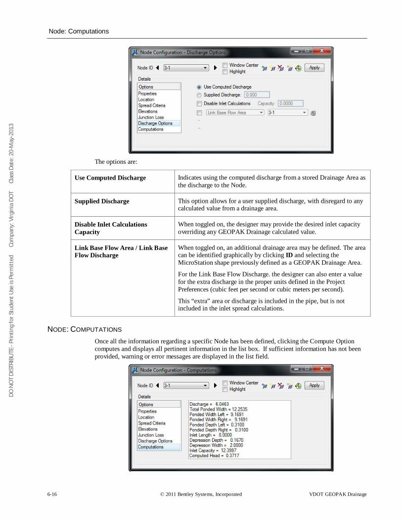
DO N
OT
DIST
RIBU
TE -
Prin
ting
for S
tude
nt U
se is
Per
mitt
ed
Co
mpa
ny: V
irgin
ia D
OT
C
lass
Dat
e: 2
0-M
ay-2
013
Node: Computations
6-16 © 2011 Bentley Systems, Incorporated VDOT GEOPAK Drainage
The options are:
Use Computed Discharge Indicates using the computed discharge from a stored Drainage Area as the discharge to the Node.
Supplied Discharge This option allows for a user supplied discharge, with disregard to any calculated value from a drainage area.
Disable Inlet Calculations Capacity
When toggled on, the designer may provide the desired inlet capacity overriding any GEOPAK Drainage calculated value.
Link Base Flow Area / Link Base Flow Discharge
When toggled on, an additional drainage area may be defined. The area can be identified graphically by clicking ID and selecting the MicroStation shape previously defined as a GEOPAK Drainage Area.
For the Link Base Flow Discharge. the designer can also enter a value for the extra discharge in the proper units defined in the Project Preferences (cubic feet per second or cubic meters per second).
This “extra” area or discharge is included in the pipe, but is not included in the inlet spread calculations.
NODE: COMPUTATIONS Once all the information regarding a specific Node has been defined, clicking the Compute Option computes and displays all pertinent information in the list box. If sufficient information has not been provided, warning or error messages are displayed in the list field.
DO N
OT
DIST
RIBU
TE -
Prin
ting
for S
tude
nt U
se is
Per
mitt
ed
Co
mpa
ny: V
irgin
ia D
OT
C
lass
Dat
e: 2
0-M
ay-2
013
Node: Computations
VDOT GEOPAK Drainage © 2011 Bentley Systems, Incorporated 6-17
Note The designer should be aware that the computations shown are the spread calculations. Therefore, the value of discharge may be different from the discharge calculated in the drainage area, since VDOT uses an absolute intensity of 4 inches/hour intensity for inlet computations. This discharge value also includes any bypass discharge added to the current node.
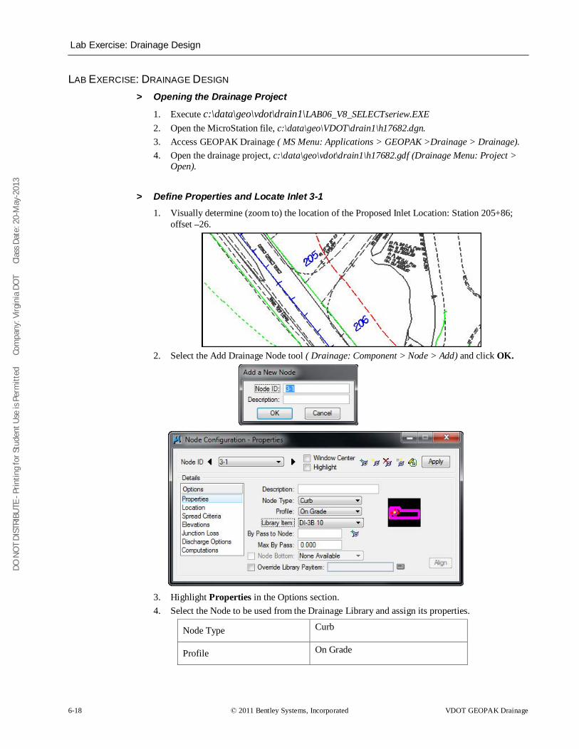
DO N
OT
DIST
RIBU
TE -
Prin
ting
for S
tude
nt U
se is
Per
mitt
ed
Co
mpa
ny: V
irgin
ia D
OT
C
lass
Dat
e: 2
0-M
ay-2
013
Lab Exercise: Drainage Design
6-18 © 2011 Bentley Systems, Incorporated VDOT GEOPAK Drainage
LAB EXERCISE: DRAINAGE DESIGN > Opening the Drainage Project
1. Execute c:\data\geo\vdot\drain1\LAB06_V8_SELECTseriew.EXE 2. Open the MicroStation file, c:\data\geo\VDOT\drain1\h17682.dgn. 3. Access GEOPAK Drainage ( MS Menu: Applications > GEOPAK >Drainage > Drainage). 4. Open the drainage project, c:\data\geo\vdot\drain1\h17682.gdf (Drainage Menu: Project >
Open).
> Define Properties and Locate Inlet 3-1 1. Visually determine (zoom to) the location of the Proposed Inlet Location: Station 205+86;
offset –26.
2. Select the Add Drainage Node tool ( Drainage: Component > Node > Add) and click OK.
3. Highlight Properties in the Options section. 4. Select the Node to be used from the Drainage Library and assign its properties.
Node Type Curb
Profile On Grade
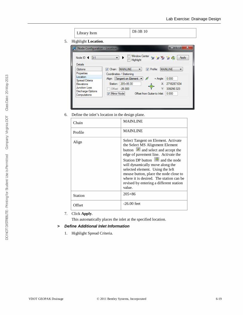
DO N
OT
DIST
RIBU
TE -
Prin
ting
for S
tude
nt U
se is
Per
mitt
ed
Co
mpa
ny: V
irgin
ia D
OT
C
lass
Dat
e: 2
0-M
ay-2
013
Lab Exercise: Drainage Design
VDOT GEOPAK Drainage © 2011 Bentley Systems, Incorporated 6-19
Library Item DI-3B 10
5. Highlight Location.
6. Define the inlet’s location in the design plane.
Chain MAINLINE
Profile MAINLINE
Align Select Tangent on Element. Activate the Select MS Alignment Element button and select and accept the edge of pavement line. Activate the Station DP button and the node will dynamically move along the selected element. Using the left mouse button, place the node close to where it is desired. The station can be revised by entering a different station value.
Station 205+86
Offset -26.00 feet
7. Click Apply. This automatically places the inlet at the specified location.
> Define Additional Inlet Information
1. Highlight Spread Criteria.
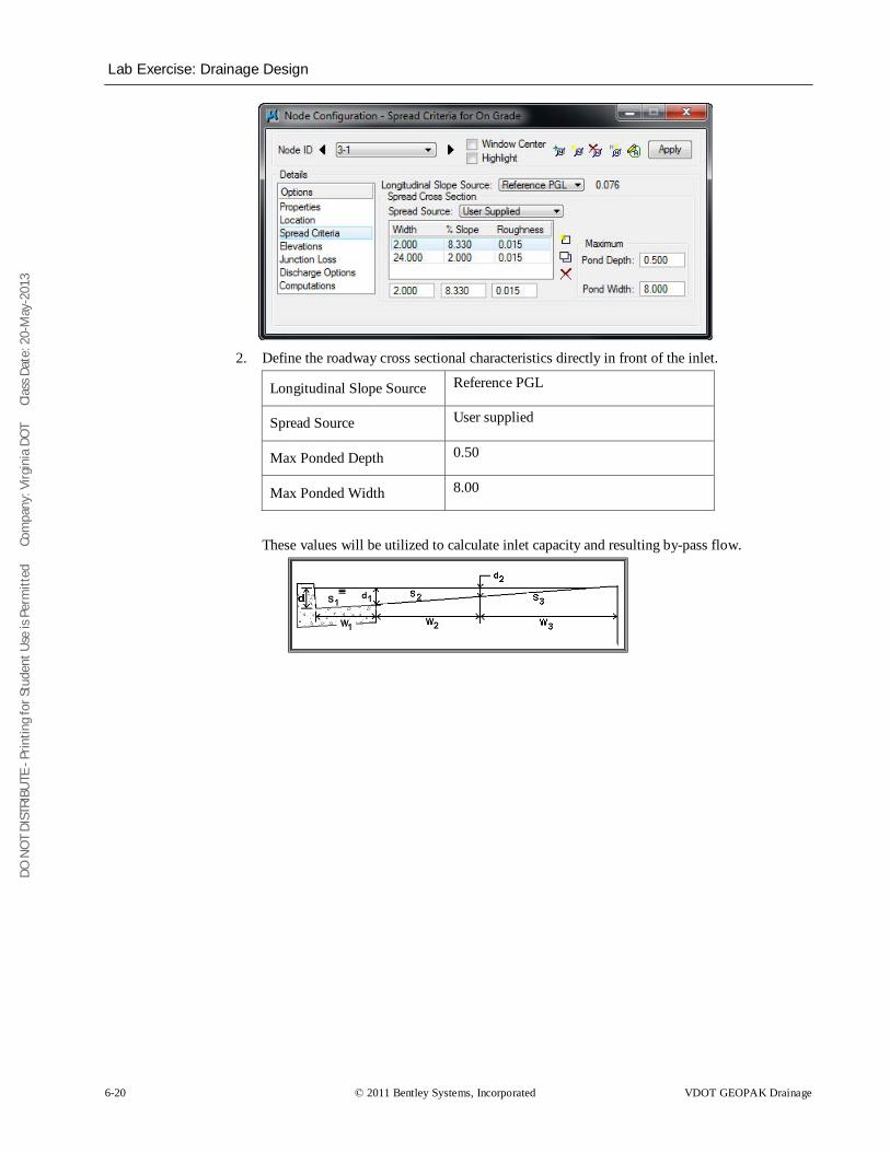
DO N
OT
DIST
RIBU
TE -
Prin
ting
for S
tude
nt U
se is
Per
mitt
ed
Co
mpa
ny: V
irgin
ia D
OT
C
lass
Dat
e: 2
0-M
ay-2
013
Lab Exercise: Drainage Design
6-20 © 2011 Bentley Systems, Incorporated VDOT GEOPAK Drainage
2. Define the roadway cross sectional characteristics directly in front of the inlet.
Longitudinal Slope Source Reference PGL
Spread Source User supplied
Max Ponded Depth 0.50
Max Ponded Width 8.00
These values will be utilized to calculate inlet capacity and resulting by-pass flow.
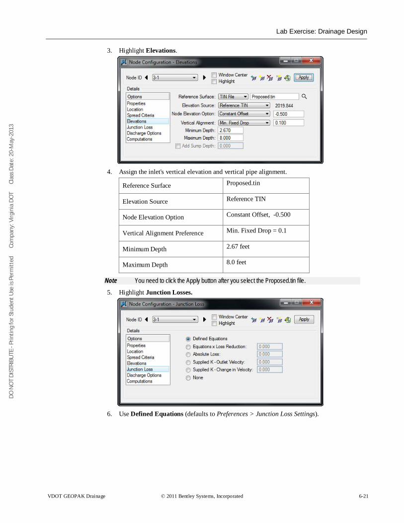
DO N
OT
DIST
RIBU
TE -
Prin
ting
for S
tude
nt U
se is
Per
mitt
ed
Co
mpa
ny: V
irgin
ia D
OT
C
lass
Dat
e: 2
0-M
ay-2
013
Lab Exercise: Drainage Design
VDOT GEOPAK Drainage © 2011 Bentley Systems, Incorporated 6-21
3. Highlight Elevations.
4. Assign the inlet's vertical elevation and vertical pipe alignment.
Reference Surface Proposed.tin
Elevation Source Reference TIN
Node Elevation Option Constant Offset, -0.500
Vertical Alignment Preference Min. Fixed Drop = 0.1
Minimum Depth 2.67 feet
Maximum Depth 8.0 feet
Note You need to click the Apply button after you select the Proposed.tin file.
5. Highlight Junction Losses.
6. Use Defined Equations (defaults to Preferences > Junction Loss Settings).
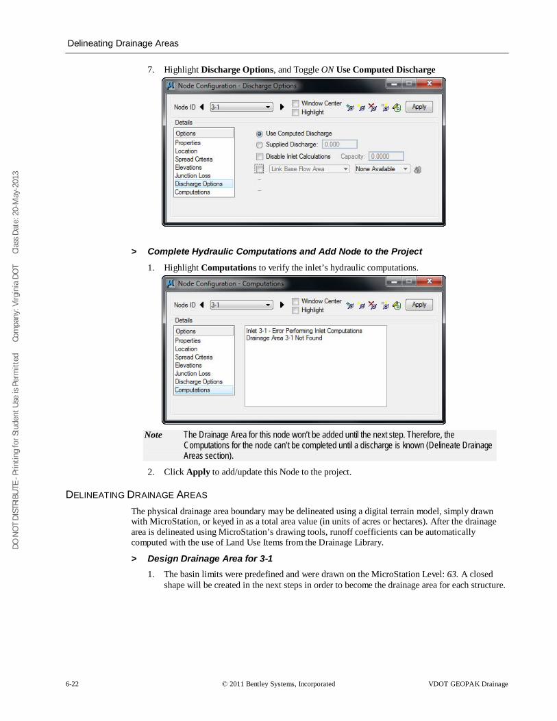
DO N
OT
DIST
RIBU
TE -
Prin
ting
for S
tude
nt U
se is
Per
mitt
ed
Co
mpa
ny: V
irgin
ia D
OT
C
lass
Dat
e: 2
0-M
ay-2
013
Delineating Drainage Areas
6-22 © 2011 Bentley Systems, Incorporated VDOT GEOPAK Drainage
7. Highlight Discharge Options, and Toggle ON Use Computed Discharge
> Complete Hydraulic Computations and Add Node to the Project
1. Highlight Computations to verify the inlet’s hydraulic computations.
Note The Drainage Area for this node won’t be added until the next step. Therefore, the
Computations for the node can’t be completed until a discharge is known (Delineate Drainage Areas section).
2. Click Apply to add/update this Node to the project.
DELINEATING DRAINAGE AREAS The physical drainage area boundary may be delineated using a digital terrain model, simply drawn with MicroStation, or keyed in as a total area value (in units of acres or hectares). After the drainage area is delineated using MicroStation’s drawing tools, runoff coefficients can be automatically computed with the use of Land Use Items from the Drainage Library.
> Design Drainage Area for 3-1 1. The basin limits were predefined and were drawn on the MicroStation Level: 63. A closed
shape will be created in the next steps in order to become the drainage area for each structure.
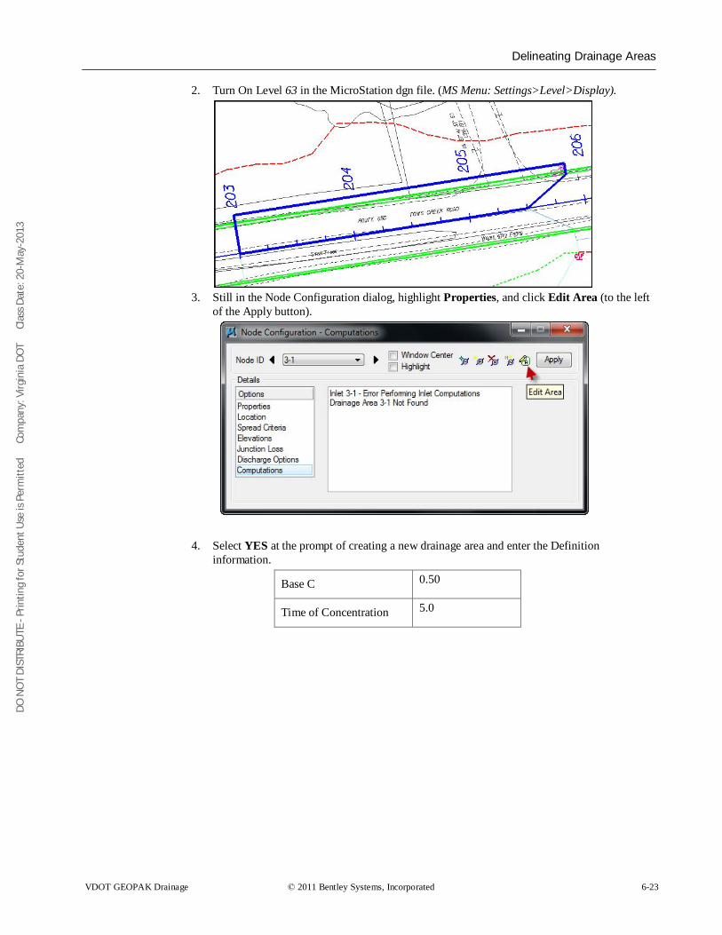
DO N
OT
DIST
RIBU
TE -
Prin
ting
for S
tude
nt U
se is
Per
mitt
ed
Co
mpa
ny: V
irgin
ia D
OT
C
lass
Dat
e: 2
0-M
ay-2
013
Delineating Drainage Areas
VDOT GEOPAK Drainage © 2011 Bentley Systems, Incorporated 6-23
2. Turn On Level 63 in the MicroStation dgn file. (MS Menu: Settings>Level>Display).
3. Still in the Node Configuration dialog, highlight Properties, and click Edit Area (to the left
of the Apply button).
4. Select YES at the prompt of creating a new drainage area and enter the Definition information.
Base C 0.50
Time of Concentration 5.0
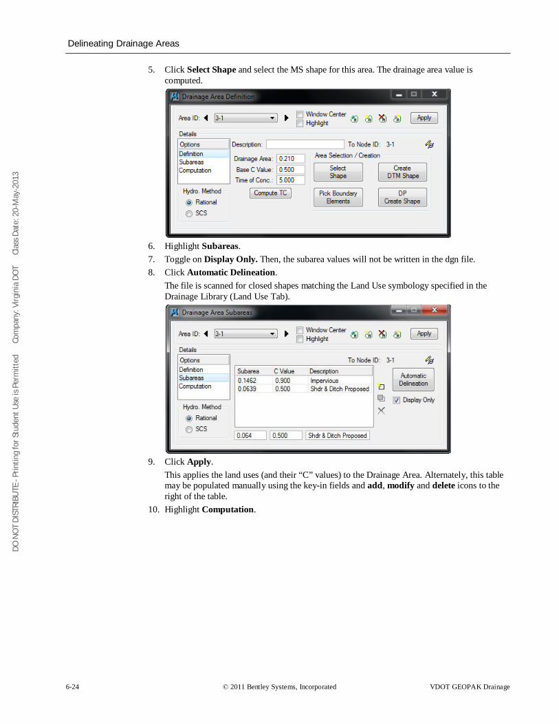
DO N
OT
DIST
RIBU
TE -
Prin
ting
for S
tude
nt U
se is
Per
mitt
ed
Co
mpa
ny: V
irgin
ia D
OT
C
lass
Dat
e: 2
0-M
ay-2
013
Delineating Drainage Areas
6-24 © 2011 Bentley Systems, Incorporated VDOT GEOPAK Drainage
5. Click Select Shape and select the MS shape for this area. The drainage area value is computed.
6. Highlight Subareas. 7. Toggle on Display Only. Then, the subarea values will not be written in the dgn file. 8. Click Automatic Delineation.
The file is scanned for closed shapes matching the Land Use symbology specified in the Drainage Library (Land Use Tab).
9. Click Apply.
This applies the land uses (and their “C” values) to the Drainage Area. Alternately, this table may be populated manually using the key-in fields and add, modify and delete icons to the right of the table.
10. Highlight Computation.
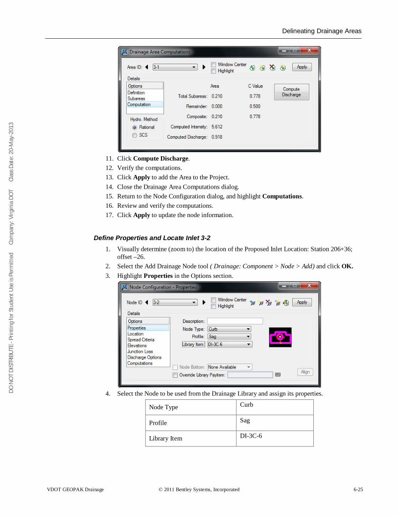
DO N
OT
DIST
RIBU
TE -
Prin
ting
for S
tude
nt U
se is
Per
mitt
ed
Co
mpa
ny: V
irgin
ia D
OT
C
lass
Dat
e: 2
0-M
ay-2
013
Delineating Drainage Areas
VDOT GEOPAK Drainage © 2011 Bentley Systems, Incorporated 6-25
11. Click Compute Discharge. 12. Verify the computations. 13. Click Apply to add the Area to the Project. 14. Close the Drainage Area Computations dialog. 15. Return to the Node Configuration dialog, and highlight Computations. 16. Review and verify the computations. 17. Click Apply to update the node information.
Define Properties and Locate Inlet 3-2 1. Visually determine (zoom to) the location of the Proposed Inlet Location: Station 206+36;
offset –26. 2. Select the Add Drainage Node tool ( Drainage: Component > Node > Add) and click OK. 3. Highlight Properties in the Options section.
4. Select the Node to be used from the Drainage Library and assign its properties.
Node Type Curb
Profile Sag
Library Item DI-3C-6
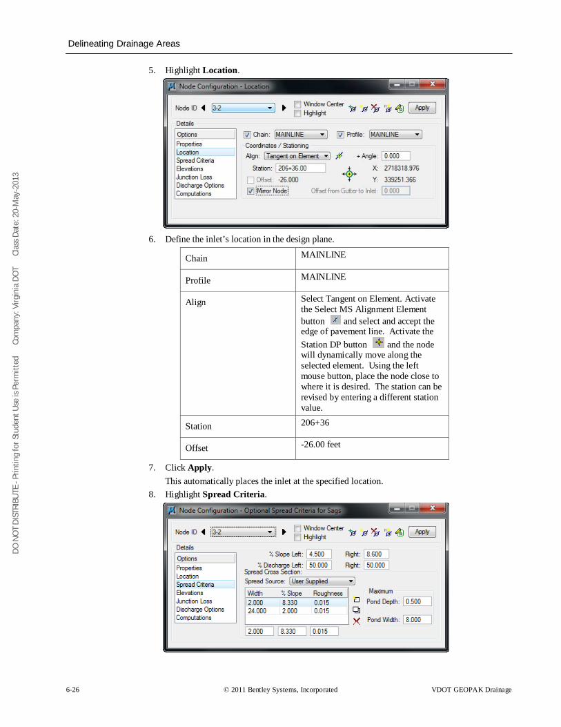
DO N
OT
DIST
RIBU
TE -
Prin
ting
for S
tude
nt U
se is
Per
mitt
ed
Co
mpa
ny: V
irgin
ia D
OT
C
lass
Dat
e: 2
0-M
ay-2
013
Delineating Drainage Areas
6-26 © 2011 Bentley Systems, Incorporated VDOT GEOPAK Drainage
5. Highlight Location.
6. Define the inlet’s location in the design plane.
Chain MAINLINE
Profile MAINLINE
Align Select Tangent on Element. Activate the Select MS Alignment Element button and select and accept the edge of pavement line. Activate the Station DP button and the node will dynamically move along the selected element. Using the left mouse button, place the node close to where it is desired. The station can be revised by entering a different station value.
Station 206+36
Offset -26.00 feet
7. Click Apply. This automatically places the inlet at the specified location.
8. Highlight Spread Criteria.
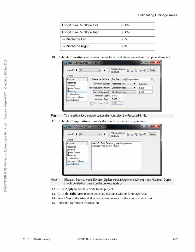
DO N
OT
DIST
RIBU
TE -
Prin
ting
for S
tude
nt U
se is
Per
mitt
ed
Co
mpa
ny: V
irgin
ia D
OT
C
lass
Dat
e: 2
0-M
ay-2
013
Delineating Drainage Areas
VDOT GEOPAK Drainage © 2011 Bentley Systems, Incorporated 6-27
Longitudinal % Slope Left 4.50%
Longitudinal % Slope Right 8.60%
% Discharge Left 50 %
% Discharge Right 50%
10. Highlight Elevations and assign the inlet's vertical elevation and vertical pipe alignment
Note You need to click the Apply button after you select the Proposed.tin file.
11. Highlight Computations to verify the inlet’s hydraulic computations.
Note Elevation Source, Node Elevation Option, vertical Alignment, Minimum and Maximum Depth
should be filled out based on the previous node 3-1.
12. Click Apply to add this Node to the project. 13. Click the Edit Area icon to associate this inlet with its Drainage Area. 14. Select Yes to the Alert dialog box, since no area for the inlet is created yet. 15. Enter the Definition information.
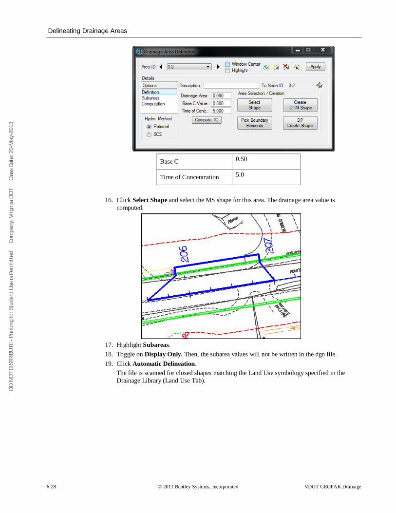
DO N
OT
DIST
RIBU
TE -
Prin
ting
for S
tude
nt U
se is
Per
mitt
ed
Co
mpa
ny: V
irgin
ia D
OT
C
lass
Dat
e: 2
0-M
ay-2
013
Delineating Drainage Areas
6-28 © 2011 Bentley Systems, Incorporated VDOT GEOPAK Drainage
Base C 0.50
Time of Concentration 5.0
16. Click Select Shape and select the MS shape for this area. The drainage area value is
computed.
17. Highlight Subareas. 18. Toggle on Display Only. Then, the subarea values will not be written in the dgn file. 19. Click Automatic Delineation.
The file is scanned for closed shapes matching the Land Use symbology specified in the Drainage Library (Land Use Tab).
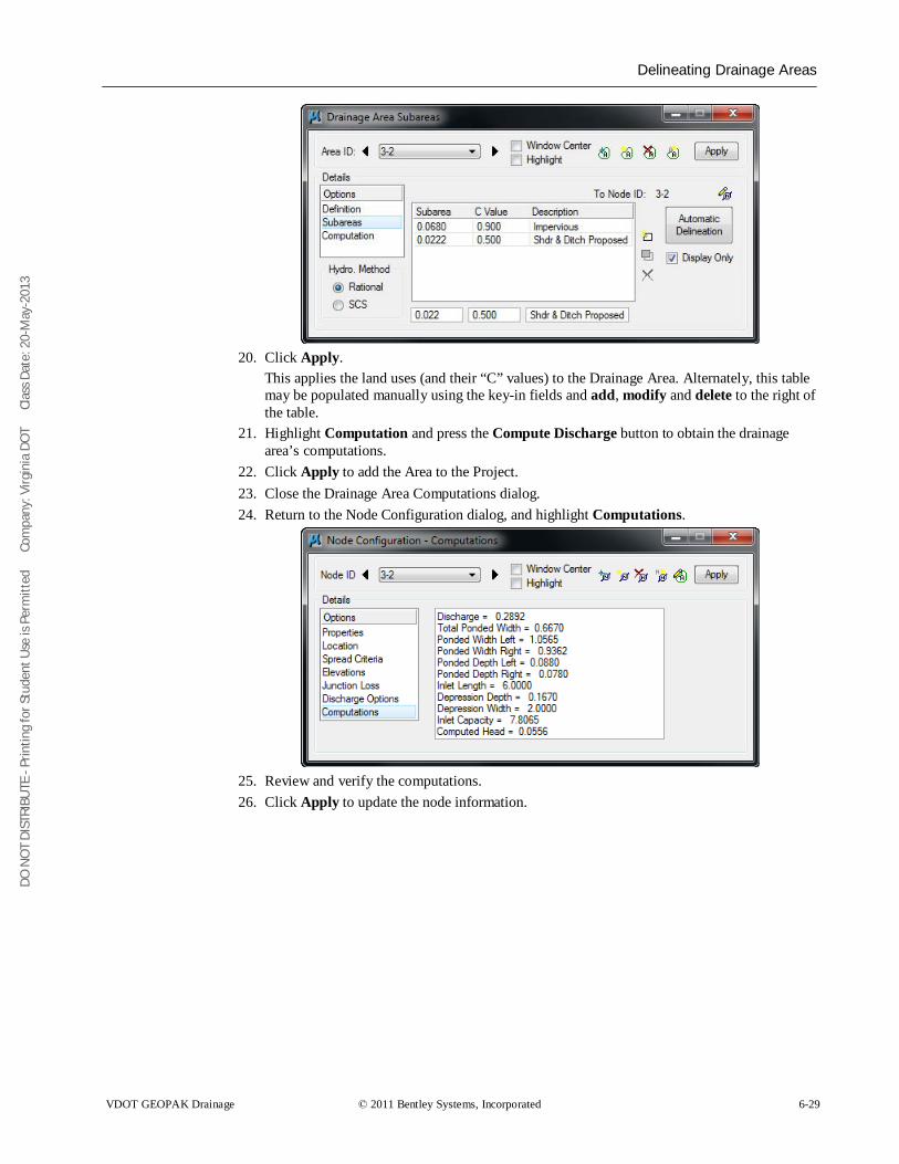
DO N
OT
DIST
RIBU
TE -
Prin
ting
for S
tude
nt U
se is
Per
mitt
ed
Co
mpa
ny: V
irgin
ia D
OT
C
lass
Dat
e: 2
0-M
ay-2
013
Delineating Drainage Areas
VDOT GEOPAK Drainage © 2011 Bentley Systems, Incorporated 6-29
20. Click Apply.
This applies the land uses (and their “C” values) to the Drainage Area. Alternately, this table may be populated manually using the key-in fields and add, modify and delete to the right of the table.
21. Highlight Computation and press the Compute Discharge button to obtain the drainage area’s computations.
22. Click Apply to add the Area to the Project. 23. Close the Drainage Area Computations dialog. 24. Return to the Node Configuration dialog, and highlight Computations.
25. Review and verify the computations. 26. Click Apply to update the node information.
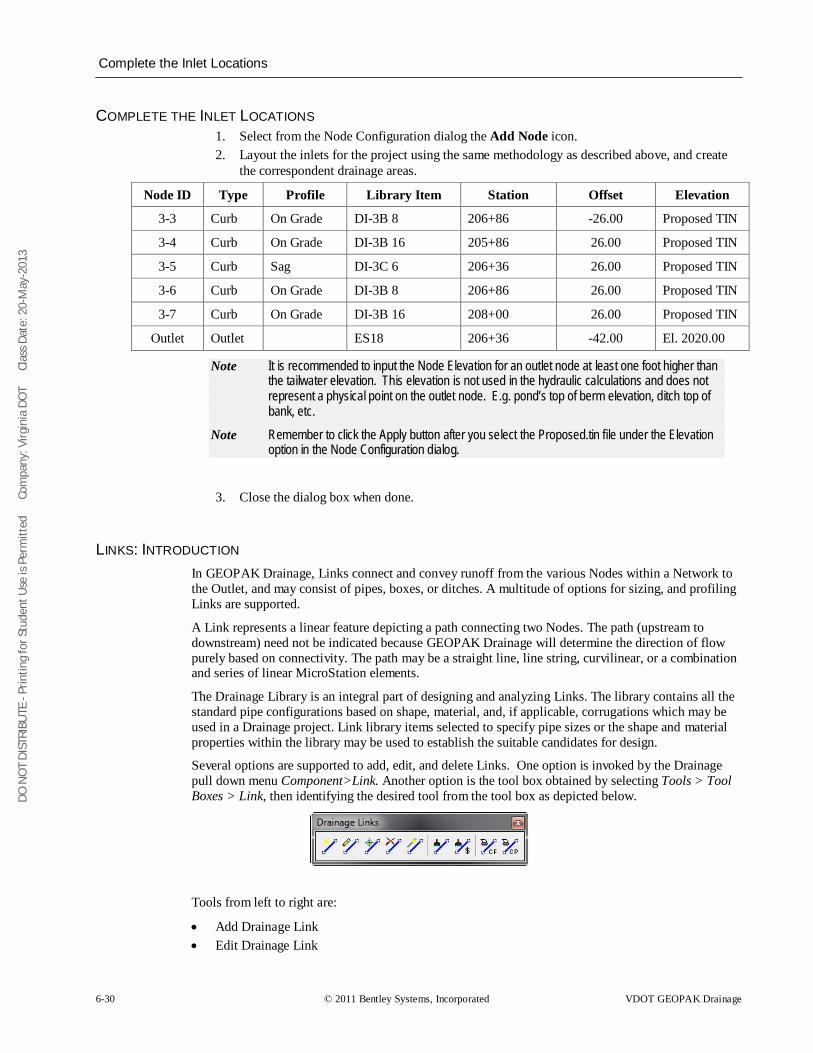
DO N
OT
DIST
RIBU
TE -
Prin
ting
for S
tude
nt U
se is
Per
mitt
ed
Co
mpa
ny: V
irgin
ia D
OT
C
lass
Dat
e: 2
0-M
ay-2
013
Complete the Inlet Locations
6-30 © 2011 Bentley Systems, Incorporated VDOT GEOPAK Drainage
COMPLETE THE INLET LOCATIONS 1. Select from the Node Configuration dialog the Add Node icon. 2. Layout the inlets for the project using the same methodology as described above, and create
the correspondent drainage areas.
Node ID Type Profile Library Item Station Offset Elevation
3-3 Curb On Grade DI-3B 8 206+86 -26.00 Proposed TIN
3-4 Curb On Grade DI-3B 16 205+86 26.00 Proposed TIN
3-5 Curb Sag DI-3C 6 206+36 26.00 Proposed TIN
3-6 Curb On Grade DI-3B 8 206+86 26.00 Proposed TIN
3-7 Curb On Grade DI-3B 16 208+00 26.00 Proposed TIN
Outlet Outlet ES18 206+36 -42.00 El. 2020.00
Note It is recommended to input the Node Elevation for an outlet node at least one foot higher than the tailwater elevation. This elevation is not used in the hydraulic calculations and does not represent a physical point on the outlet node. E.g. pond’s top of berm elevation, ditch top of bank, etc.
Note Remember to click the Apply button after you select the Proposed.tin file under the Elevation option in the Node Configuration dialog.
3. Close the dialog box when done.
LINKS: INTRODUCTION In GEOPAK Drainage, Links connect and convey runoff from the various Nodes within a Network to the Outlet, and may consist of pipes, boxes, or ditches. A multitude of options for sizing, and profiling Links are supported.
A Link represents a linear feature depicting a path connecting two Nodes. The path (upstream to downstream) need not be indicated because GEOPAK Drainage will determine the direction of flow purely based on connectivity. The path may be a straight line, line string, curvilinear, or a combination and series of linear MicroStation elements.
The Drainage Library is an integral part of designing and analyzing Links. The library contains all the standard pipe configurations based on shape, material, and, if applicable, corrugations which may be used in a Drainage project. Link library items selected to specify pipe sizes or the shape and material properties within the library may be used to establish the suitable candidates for design.
Several options are supported to add, edit, and delete Links. One option is invoked by the Drainage pull down menu Component>Link. Another option is the tool box obtained by selecting Tools > Tool Boxes > Link, then identifying the desired tool from the tool box as depicted below.
Tools from left to right are:
• Add Drainage Link • Edit Drainage Link
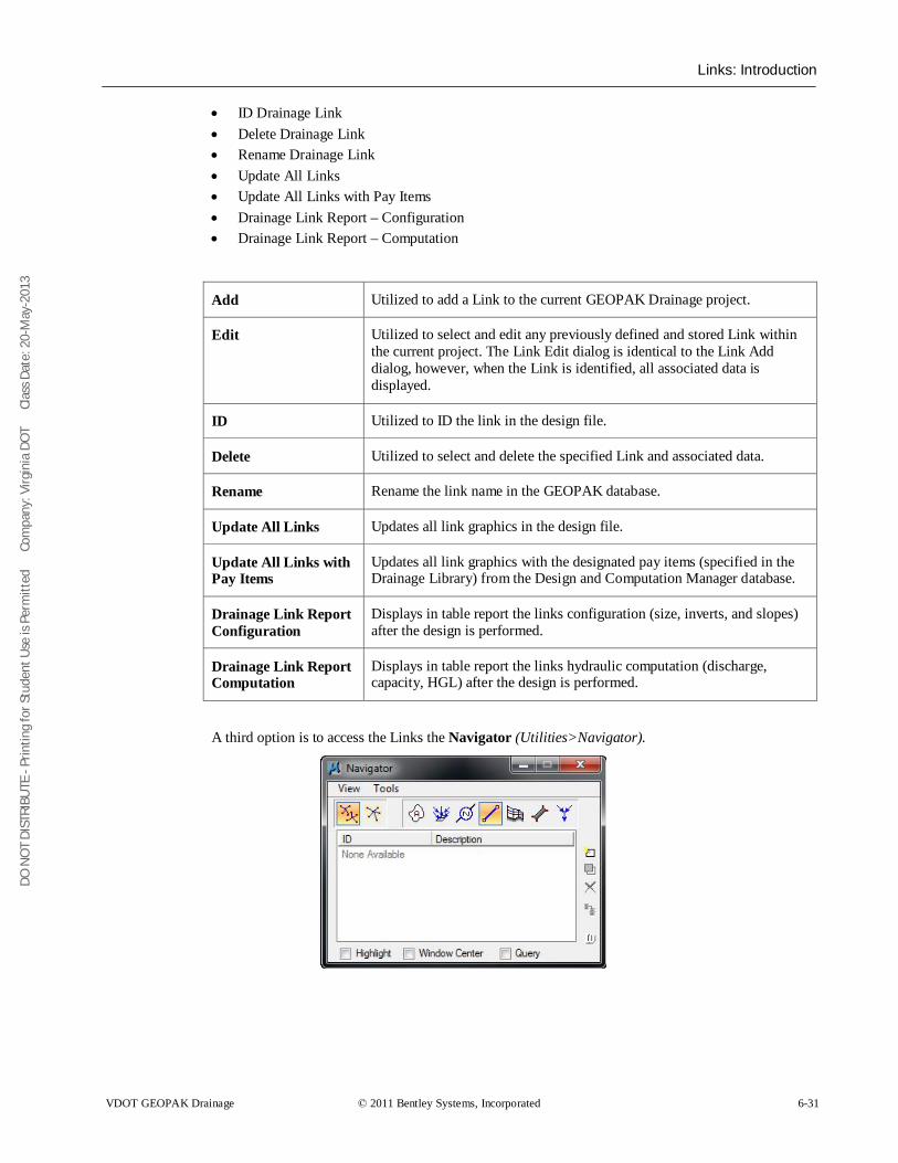
DO N
OT
DIST
RIBU
TE -
Prin
ting
for S
tude
nt U
se is
Per
mitt
ed
Co
mpa
ny: V
irgin
ia D
OT
C
lass
Dat
e: 2
0-M
ay-2
013
Links: Introduction
VDOT GEOPAK Drainage © 2011 Bentley Systems, Incorporated 6-31
• ID Drainage Link • Delete Drainage Link • Rename Drainage Link • Update All Links • Update All Links with Pay Items • Drainage Link Report – Configuration • Drainage Link Report – Computation
Add Utilized to add a Link to the current GEOPAK Drainage project.
Edit Utilized to select and edit any previously defined and stored Link within the current project. The Link Edit dialog is identical to the Link Add dialog, however, when the Link is identified, all associated data is displayed.
ID Utilized to ID the link in the design file.
Delete Utilized to select and delete the specified Link and associated data.
Rename Rename the link name in the GEOPAK database.
Update All Links Updates all link graphics in the design file.
Update All Links with Pay Items
Updates all link graphics with the designated pay items (specified in the Drainage Library) from the Design and Computation Manager database.
Drainage Link Report Configuration
Displays in table report the links configuration (size, inverts, and slopes) after the design is performed.
Drainage Link Report Computation
Displays in table report the links hydraulic computation (discharge, capacity, HGL) after the design is performed.
A third option is to access the Links the Navigator (Utilities>Navigator).
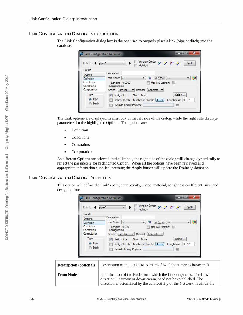
DO N
OT
DIST
RIBU
TE -
Prin
ting
for S
tude
nt U
se is
Per
mitt
ed
Co
mpa
ny: V
irgin
ia D
OT
C
lass
Dat
e: 2
0-M
ay-2
013
Link Configuration Dialog: Introduction
6-32 © 2011 Bentley Systems, Incorporated VDOT GEOPAK Drainage
LINK CONFIGURATION DIALOG: INTRODUCTION The Link Configuration dialog box is the one used to properly place a link (pipe or ditch) into the database.
The Link options are displayed in a list box in the left side of the dialog, while the right side displays parameters for the highlighted Option. The options are:
• Definition
• Conditions
• Constraints
• Computation
As different Options are selected in the list box, the right side of the dialog will change dynamically to reflect the parameters for highlighted Option. When all the options have been reviewed and appropriate information supplied, pressing the Apply button will update the Drainage database.
LINK CONFIGURATION DIALOG: DEFINITION This option will define the Link’s path, connectivity, shape, material, roughness coefficient, size, and design options.
Description (optional) Description of the Link. (Maximum of 32 alphanumeric characters.)
From Node Identification of the Node from which the Link originates. The flow direction, upstream or downstream, need not be established. The direction is determined by the connectivity of the Network in which the
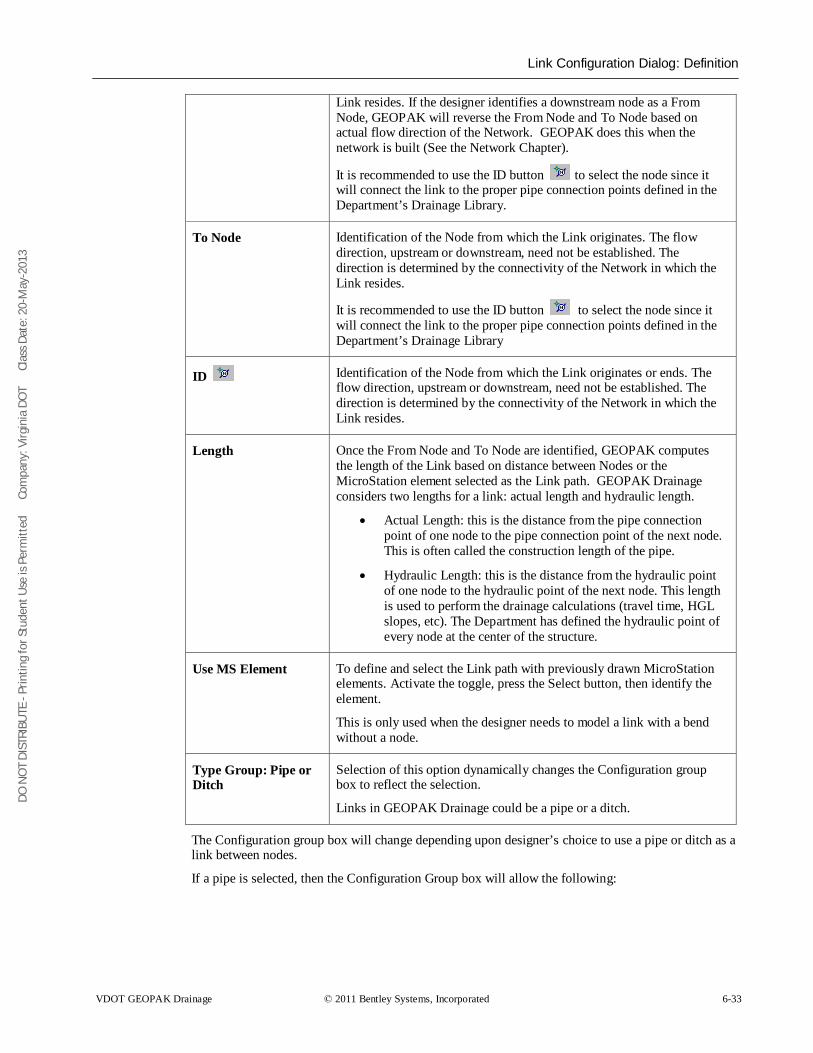
DO N
OT
DIST
RIBU
TE -
Prin
ting
for S
tude
nt U
se is
Per
mitt
ed
Co
mpa
ny: V
irgin
ia D
OT
C
lass
Dat
e: 2
0-M
ay-2
013
Link Configuration Dialog: Definition
VDOT GEOPAK Drainage © 2011 Bentley Systems, Incorporated 6-33
Link resides. If the designer identifies a downstream node as a From Node, GEOPAK will reverse the From Node and To Node based on actual flow direction of the Network. GEOPAK does this when the network is built (See the Network Chapter).
It is recommended to use the ID button to select the node since it will connect the link to the proper pipe connection points defined in the Department’s Drainage Library.
To Node Identification of the Node from which the Link originates. The flow direction, upstream or downstream, need not be established. The direction is determined by the connectivity of the Network in which the Link resides.
It is recommended to use the ID button to select the node since it will connect the link to the proper pipe connection points defined in the Department’s Drainage Library
ID Identification of the Node from which the Link originates or ends. The flow direction, upstream or downstream, need not be established. The direction is determined by the connectivity of the Network in which the Link resides.
Length Once the From Node and To Node are identified, GEOPAK computes the length of the Link based on distance between Nodes or the MicroStation element selected as the Link path. GEOPAK Drainage considers two lengths for a link: actual length and hydraulic length.
• Actual Length: this is the distance from the pipe connection point of one node to the pipe connection point of the next node. This is often called the construction length of the pipe.
• Hydraulic Length: this is the distance from the hydraulic point of one node to the hydraulic point of the next node. This length is used to perform the drainage calculations (travel time, HGL slopes, etc). The Department has defined the hydraulic point of every node at the center of the structure.
Use MS Element To define and select the Link path with previously drawn MicroStation elements. Activate the toggle, press the Select button, then identify the element.
This is only used when the designer needs to model a link with a bend without a node.
Type Group: Pipe or Ditch
Selection of this option dynamically changes the Configuration group box to reflect the selection.
Links in GEOPAK Drainage could be a pipe or a ditch.
The Configuration group box will change depending upon designer’s choice to use a pipe or ditch as a link between nodes.
If a pipe is selected, then the Configuration Group box will allow the following:
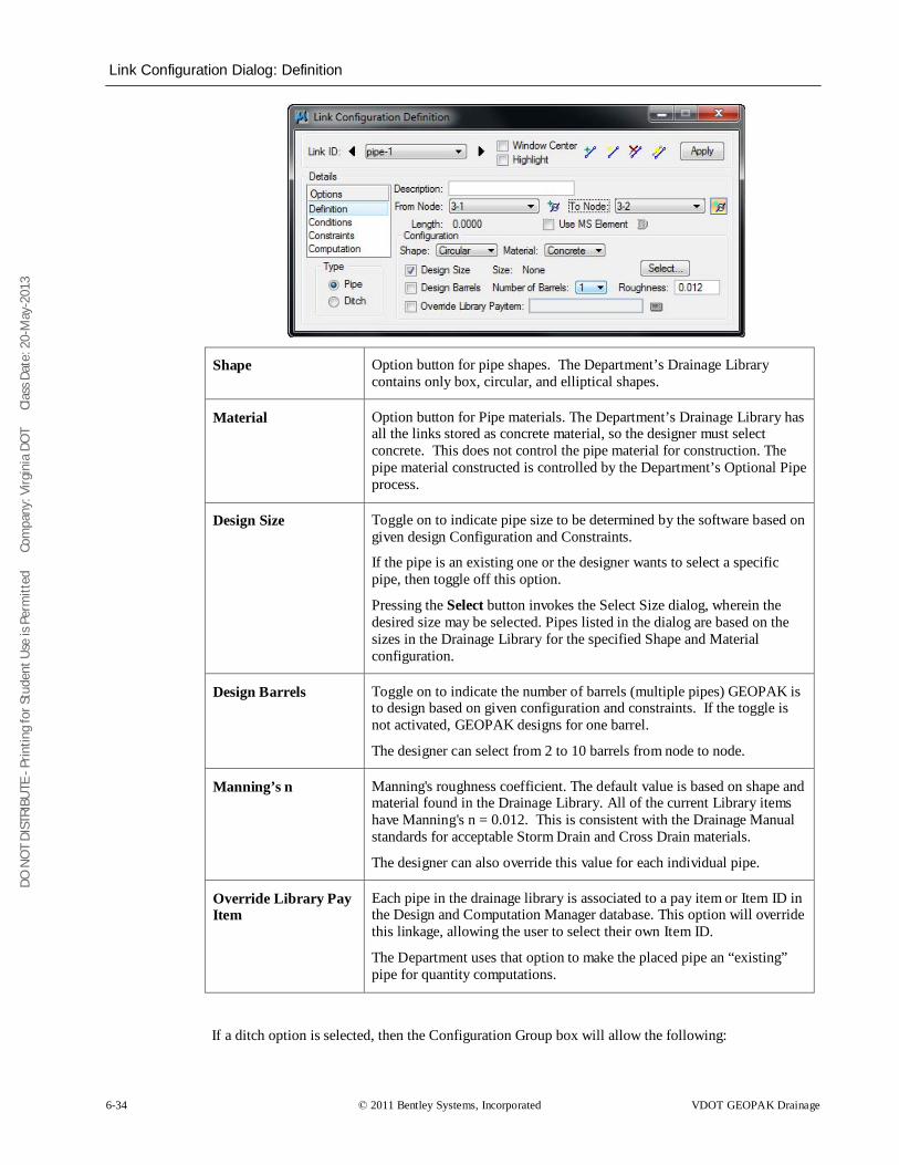
DO N
OT
DIST
RIBU
TE -
Prin
ting
for S
tude
nt U
se is
Per
mitt
ed
Co
mpa
ny: V
irgin
ia D
OT
C
lass
Dat
e: 2
0-M
ay-2
013
Link Configuration Dialog: Definition
6-34 © 2011 Bentley Systems, Incorporated VDOT GEOPAK Drainage
Shape Option button for pipe shapes. The Department’s Drainage Library contains only box, circular, and elliptical shapes.
Material Option button for Pipe materials. The Department’s Drainage Library has all the links stored as concrete material, so the designer must select concrete. This does not control the pipe material for construction. The pipe material constructed is controlled by the Department’s Optional Pipe process.
Design Size Toggle on to indicate pipe size to be determined by the software based on given design Configuration and Constraints.
If the pipe is an existing one or the designer wants to select a specific pipe, then toggle off this option.
Pressing the Select button invokes the Select Size dialog, wherein the desired size may be selected. Pipes listed in the dialog are based on the sizes in the Drainage Library for the specified Shape and Material configuration.
Design Barrels Toggle on to indicate the number of barrels (multiple pipes) GEOPAK is to design based on given configuration and constraints. If the toggle is not activated, GEOPAK designs for one barrel.
The designer can select from 2 to 10 barrels from node to node.
Manning’s n Manning's roughness coefficient. The default value is based on shape and material found in the Drainage Library. All of the current Library items have Manning's n = 0.012. This is consistent with the Drainage Manual standards for acceptable Storm Drain and Cross Drain materials.
The designer can also override this value for each individual pipe.
Override Library Pay Item
Each pipe in the drainage library is associated to a pay item or Item ID in the Design and Computation Manager database. This option will override this linkage, allowing the user to select their own Item ID.
The Department uses that option to make the placed pipe an “existing” pipe for quantity computations.
If a ditch option is selected, then the Configuration Group box will allow the following:
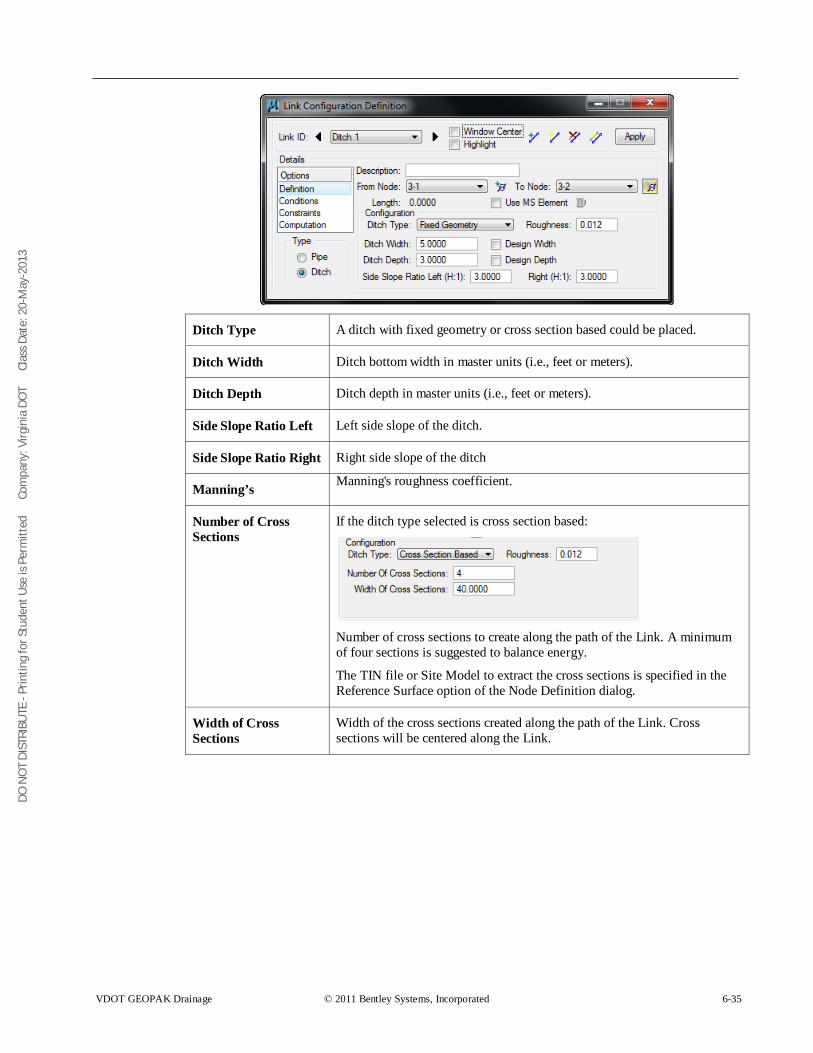
DO N
OT
DIST
RIBU
TE -
Prin
ting
for S
tude
nt U
se is
Per
mitt
ed
Co
mpa
ny: V
irgin
ia D
OT
C
lass
Dat
e: 2
0-M
ay-2
013
VDOT GEOPAK Drainage © 2011 Bentley Systems, Incorporated 6-35
Ditch Type A ditch with fixed geometry or cross section based could be placed.
Ditch Width Ditch bottom width in master units (i.e., feet or meters).
Ditch Depth Ditch depth in master units (i.e., feet or meters).
Side Slope Ratio Left Left side slope of the ditch.
Side Slope Ratio Right Right side slope of the ditch
Manning’s Manning's roughness coefficient.
Number of Cross Sections
If the ditch type selected is cross section based:
Number of cross sections to create along the path of the Link. A minimum of four sections is suggested to balance energy.
The TIN file or Site Model to extract the cross sections is specified in the Reference Surface option of the Node Definition dialog.
Width of Cross Sections
Width of the cross sections created along the path of the Link. Cross sections will be centered along the Link.
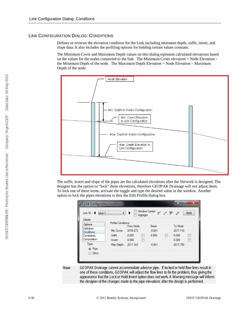
DO N
OT
DIST
RIBU
TE -
Prin
ting
for S
tude
nt U
se is
Per
mitt
ed
Co
mpa
ny: V
irgin
ia D
OT
C
lass
Dat
e: 2
0-M
ay-2
013
Link Configuration Dialog: Conditions
6-36 © 2011 Bentley Systems, Incorporated VDOT GEOPAK Drainage
LINK CONFIGURATION DIALOG: CONDITIONS Defines or reviews the elevation condition for the Link including minimum depth, soffit, invert, and slope data. It also includes the profiling options for holding certain values constant.
The Minimum Cover and Maximum Depth values on this dialog represent calculated elevations based on the values for the nodes connected to the link. The Minimum Cover elevation = Node Elevation - the Minimum Depth of the node. The Maximum Depth Elevation = Node Elevation – Maximum Depth of the node.
The soffit, invert and slope of the pipes are the calculated elevations after the Network is designed. The designer has the option to “lock” these elevations, therefore GEOPAK Drainage will not adjust them. To lock one of these items, activate the toggle and type the desired value in the window. Another option to lock the pipes elevations is thru the Edit Profile dialog box.
Note GEOPAK Drainage cannot accommodate adverse pipe. If locked or held flow lines result in
one of these conditions, GEOPAK will adjust the flow lines to fix the problem, thus giving the appearance that the Lock or Hold Invert option does not work. A Warning message will inform the designer of the changes made to the pipe elevations after the design is performed.
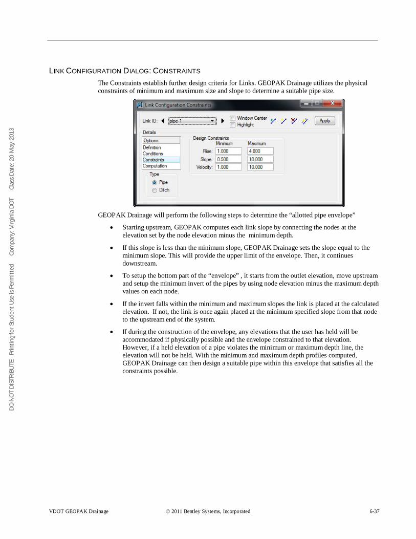
DO N
OT
DIST
RIBU
TE -
Prin
ting
for S
tude
nt U
se is
Per
mitt
ed
Co
mpa
ny: V
irgin
ia D
OT
C
lass
Dat
e: 2
0-M
ay-2
013
VDOT GEOPAK Drainage © 2011 Bentley Systems, Incorporated 6-37
LINK CONFIGURATION DIALOG: CONSTRAINTS The Constraints establish further design criteria for Links. GEOPAK Drainage utilizes the physical constraints of minimum and maximum size and slope to determine a suitable pipe size.
GEOPAK Drainage will perform the following steps to determine the “allotted pipe envelope”
• Starting upstream, GEOPAK computes each link slope by connecting the nodes at the elevation set by the node elevation minus the minimum depth.
• If this slope is less than the minimum slope, GEOPAK Drainage sets the slope equal to the minimum slope. This will provide the upper limit of the envelope. Then, it continues downstream.
• To setup the bottom part of the “envelope” , it starts from the outlet elevation, move upstream and setup the minimum invert of the pipes by using node elevation minus the maximum depth values on each node.
• If the invert falls within the minimum and maximum slopes the link is placed at the calculated elevation. If not, the link is once again placed at the minimum specified slope from that node to the upstream end of the system.
• If during the construction of the envelope, any elevations that the user has held will be accommodated if physically possible and the envelope constrained to that elevation. However, if a held elevation of a pipe violates the minimum or maximum depth line, the elevation will not be held. With the minimum and maximum depth profiles computed, GEOPAK Drainage can then design a suitable pipe within this envelope that satisfies all the constraints possible.
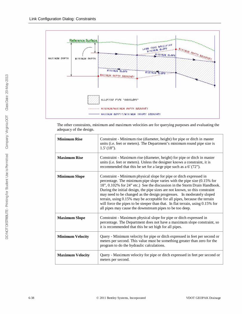
DO N
OT
DIST
RIBU
TE -
Prin
ting
for S
tude
nt U
se is
Per
mitt
ed
Co
mpa
ny: V
irgin
ia D
OT
C
lass
Dat
e: 2
0-M
ay-2
013
Link Configuration Dialog: Constraints
6-38 © 2011 Bentley Systems, Incorporated VDOT GEOPAK Drainage
The other constraints, minimum and maximum velocities are for querying purposes and evaluating the adequacy of the design.
Minimum Rise Constraint - Minimum rise (diameter, height) for pipe or ditch in master units (i.e. feet or meters). The Department’s minimum round pipe size is 1.5' (18”).
Maximum Rise Constraint - Maximum rise (diameter, height) for pipe or ditch in master units (i.e. feet or meters). Unless the designer knows a constraint, it is recommended that this be set for a large pipe such as a 6' (72”).
Minimum Slope Constraint - Minimum physical slope for pipe or ditch expressed in percentage. The minimum pipe slope varies with the pipe size (0.15% for 18”, 0.102% for 24” etc.) See the discussion in the Storm Drain Handbook. During the initial design, the pipe sizes are not known, so this constraint may need to be changed as the design progresses. In moderately sloped terrain, using 0.15% may be acceptable for all pipes, because the terrain will force the pipes to be steeper than that. In flat terrain, using 0.15% for all pipes may cause the downstream pipes to be too deep.
Maximum Slope Constraint - Maximum physical slope for pipe or ditch expressed in percentage. The Department does not have a maximum slope constraint, so it is recommended that this be set high for all pipes.
Minimum Velocity Query - Minimum velocity for pipe or ditch expressed in feet per second or meters per second. This value must be something greater than zero for the program to do the hydraulic calculations.
Maximum Velocity Query - Maximum velocity for pipe or ditch expressed in feet per second or meters per second.
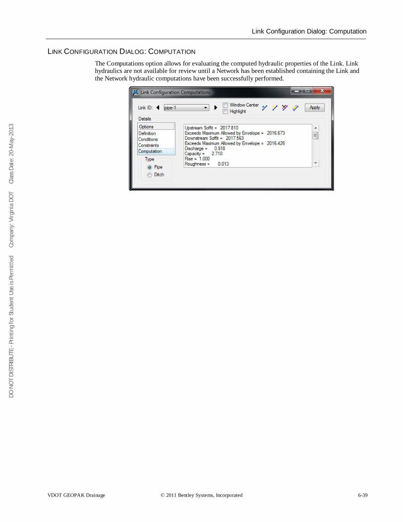
DO N
OT
DIST
RIBU
TE -
Prin
ting
for S
tude
nt U
se is
Per
mitt
ed
Co
mpa
ny: V
irgin
ia D
OT
C
lass
Dat
e: 2
0-M
ay-2
013
Link Configuration Dialog: Computation
VDOT GEOPAK Drainage © 2011 Bentley Systems, Incorporated 6-39
LINK CONFIGURATION DIALOG: COMPUTATION The Computations option allows for evaluating the computed hydraulic properties of the Link. Link hydraulics are not available for review until a Network has been established containing the Link and the Network hydraulic computations have been successfully performed.
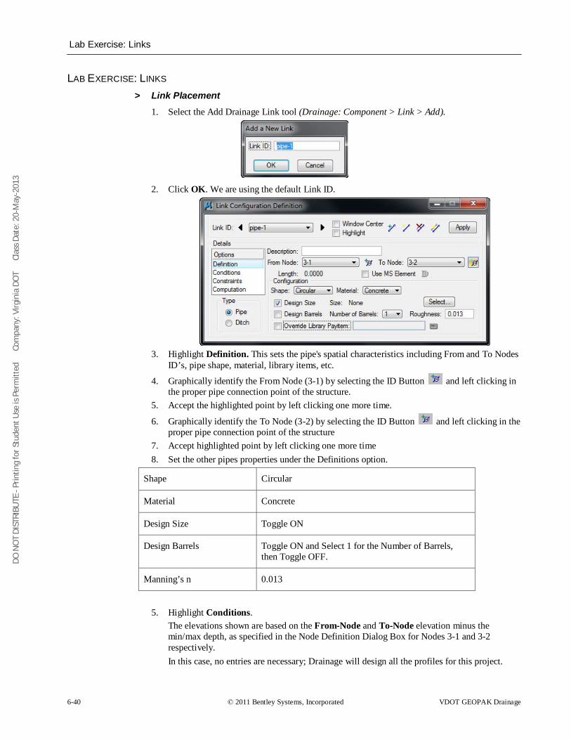
DO N
OT
DIST
RIBU
TE -
Prin
ting
for S
tude
nt U
se is
Per
mitt
ed
Co
mpa
ny: V
irgin
ia D
OT
C
lass
Dat
e: 2
0-M
ay-2
013
Lab Exercise: Links
6-40 © 2011 Bentley Systems, Incorporated VDOT GEOPAK Drainage
LAB EXERCISE: LINKS > Link Placement
1. Select the Add Drainage Link tool (Drainage: Component > Link > Add).
2. Click OK. We are using the default Link ID.
3. Highlight Definition. This sets the pipe's spatial characteristics including From and To Nodes
ID’s, pipe shape, material, library items, etc.
4. Graphically identify the From Node (3-1) by selecting the ID Button and left clicking in the proper pipe connection point of the structure.
5. Accept the highlighted point by left clicking one more time.
6. Graphically identify the To Node (3-2) by selecting the ID Button and left clicking in the proper pipe connection point of the structure
7. Accept highlighted point by left clicking one more time 8. Set the other pipes properties under the Definitions option.
Shape Circular
Material Concrete
Design Size Toggle ON
Design Barrels Toggle ON and Select 1 for the Number of Barrels, then Toggle OFF.
Manning’s n 0.013
5. Highlight Conditions.
The elevations shown are based on the From-Node and To-Node elevation minus the min/max depth, as specified in the Node Definition Dialog Box for Nodes 3-1 and 3-2 respectively. In this case, no entries are necessary; Drainage will design all the profiles for this project.
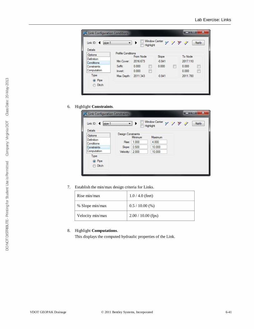
DO N
OT
DIST
RIBU
TE -
Prin
ting
for S
tude
nt U
se is
Per
mitt
ed
Co
mpa
ny: V
irgin
ia D
OT
C
lass
Dat
e: 2
0-M
ay-2
013
Lab Exercise: Links
VDOT GEOPAK Drainage © 2011 Bentley Systems, Incorporated 6-41
6. Highlight Constraints.
7. Establish the min/max design criteria for Links.
Rise min/max 1.0 / 4.0 (feet)
% Slope min/max 0.5 / 10.00 (%)
Velocity min/max 2.00 / 10.00 (fps)
8. Highlight Computations.
This displays the computed hydraulic properties of the Link.
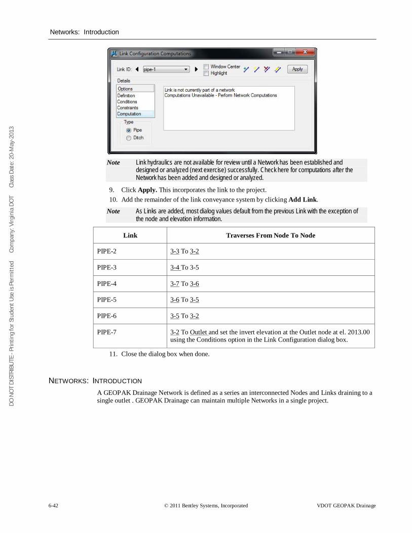
DO N
OT
DIST
RIBU
TE -
Prin
ting
for S
tude
nt U
se is
Per
mitt
ed
Co
mpa
ny: V
irgin
ia D
OT
C
lass
Dat
e: 2
0-M
ay-2
013
Networks: Introduction
6-42 © 2011 Bentley Systems, Incorporated VDOT GEOPAK Drainage
Note Link hydraulics are not available for review until a Network has been established and
designed or analyzed (next exercise) successfully. Check here for computations after the Network has been added and designed or analyzed.
9. Click Apply. This incorporates the link to the project. 10. Add the remainder of the link conveyance system by clicking Add Link.
Note As Links are added, most dialog values default from the previous Link with the exception of the node and elevation information.
Link Traverses From Node To Node
PIPE-2 3-3 To
PIPE-3
3-2
3-4
PIPE-4
To 3-5
3-7 To
PIPE-5
3-6
3-6 To
PIPE-6
3-5
3-5 To
PIPE-7
3-2
3-2 To Outlet
11. Close the dialog box when done.
and set the invert elevation at the Outlet node at el. 2013.00 using the Conditions option in the Link Configuration dialog box.
NETWORKS: INTRODUCTION A GEOPAK Drainage Network is defined as a series an interconnected Nodes and Links draining to a single outlet . GEOPAK Drainage can maintain multiple Networks in a single project.
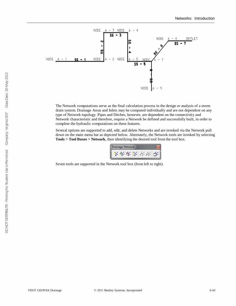
DO N
OT
DIST
RIBU
TE -
Prin
ting
for S
tude
nt U
se is
Per
mitt
ed
Co
mpa
ny: V
irgin
ia D
OT
C
lass
Dat
e: 2
0-M
ay-2
013
Networks: Introduction
VDOT GEOPAK Drainage © 2011 Bentley Systems, Incorporated 6-43
The Network computations serve as the final calculation process in the design or analysis of a storm drain system. Drainage Areas and Inlets may be computed individually and are not dependent on any type of Network topology. Pipes and Ditches, however, are dependent on the connectivity and Network characteristic and therefore, require a Network be defined and successfully built, in order to complete the hydraulic computations on these features.
Several options are supported to add, edit, and delete Networks and are invoked via the Network pull down on the main menu bar as depicted below. Alternately, the Network tools are invoked by selecting Tools > Tool Boxes > Network, then identifying the desired tool from the tool box.
Seven tools are supported in the Network tool box (from left to right).
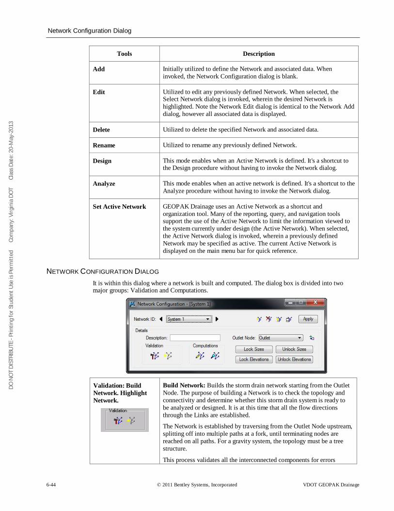
DO N
OT
DIST
RIBU
TE -
Prin
ting
for S
tude
nt U
se is
Per
mitt
ed
Co
mpa
ny: V
irgin
ia D
OT
C
lass
Dat
e: 2
0-M
ay-2
013
Network Configuration Dialog
6-44 © 2011 Bentley Systems, Incorporated VDOT GEOPAK Drainage
Tools Description
Add Initially utilized to define the Network and associated data. When invoked, the Network Configuration dialog is blank.
Edit Utilized to edit any previously defined Network. When selected, the Select Network dialog is invoked, wherein the desired Network is highlighted. Note the Network Edit dialog is identical to the Network Add dialog, however all associated data is displayed.
Delete Utilized to delete the specified Network and associated data.
Rename Utilized to rename any previously defined Network.
Design This mode enables when an Active Network is defined. It's a shortcut to the Design procedure without having to invoke the Network dialog.
Analyze This mode enables when an active network is defined. It's a shortcut to the Analyze procedure without having to invoke the Network dialog.
Set Active Network GEOPAK Drainage uses an Active Network as a shortcut and organization tool. Many of the reporting, query, and navigation tools support the use of the Active Network to limit the information viewed to the system currently under design (the Active Network). When selected, the Active Network dialog is invoked, wherein a previously defined Network may be specified as active. The current Active Network is displayed on the main menu bar for quick reference.
NETWORK CONFIGURATION DIALOG It is within this dialog where a network is built and computed. The dialog box is divided into two major groups: Validation and Computations.
Validation: Build Network. Highlight Network.
Build Network: Builds the storm drain network starting from the Outlet Node. The purpose of building a Network is to check the topology and connectivity and determine whether this storm drain system is ready to be analyzed or designed. It is at this time that all the flow directions through the Links are established.
The Network is established by traversing from the Outlet Node upstream, splitting off into multiple paths at a fork, until terminating nodes are reached on all paths. For a gravity system, the topology must be a tree structure.
This process validates all the interconnected components for errors
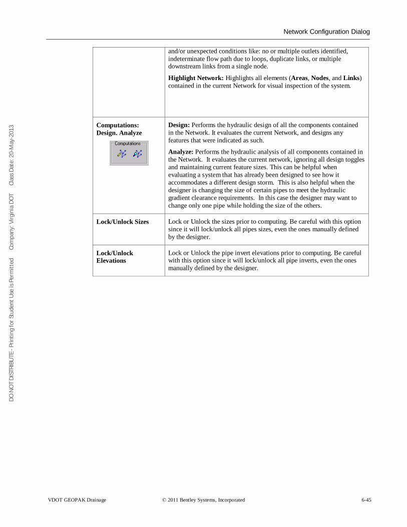
DO N
OT
DIST
RIBU
TE -
Prin
ting
for S
tude
nt U
se is
Per
mitt
ed
Co
mpa
ny: V
irgin
ia D
OT
C
lass
Dat
e: 2
0-M
ay-2
013
Network Configuration Dialog
VDOT GEOPAK Drainage © 2011 Bentley Systems, Incorporated 6-45
and/or unexpected conditions like: no or multiple outlets identified, indeterminate flow path due to loops, duplicate links, or multiple downstream links from a single node.
Highlight Network: Highlights all elements (Areas, Nodes, and Links) contained in the current Network for visual inspection of the system.
Computations: Design. Analyze
Design: Performs the hydraulic design of all the components contained in the Network. It evaluates the current Network, and designs any features that were indicated as such.
Analyze: Performs the hydraulic analysis of all components contained in the Network. It evaluates the current network, ignoring all design toggles and maintaining current feature sizes. This can be helpful when evaluating a system that has already been designed to see how it accommodates a different design storm. This is also helpful when the designer is changing the size of certain pipes to meet the hydraulic gradient clearance requirements. In this case the designer may want to change only one pipe while holding the size of the others.
Lock/Unlock Sizes Lock or Unlock the sizes prior to computing. Be careful with this option since it will lock/unlock all pipes sizes, even the ones manually defined by the designer.
Lock/Unlock Elevations
Lock or Unlock the pipe invert elevations prior to computing. Be careful with this option since it will lock/unlock all pipe inverts, even the ones manually defined by the designer.
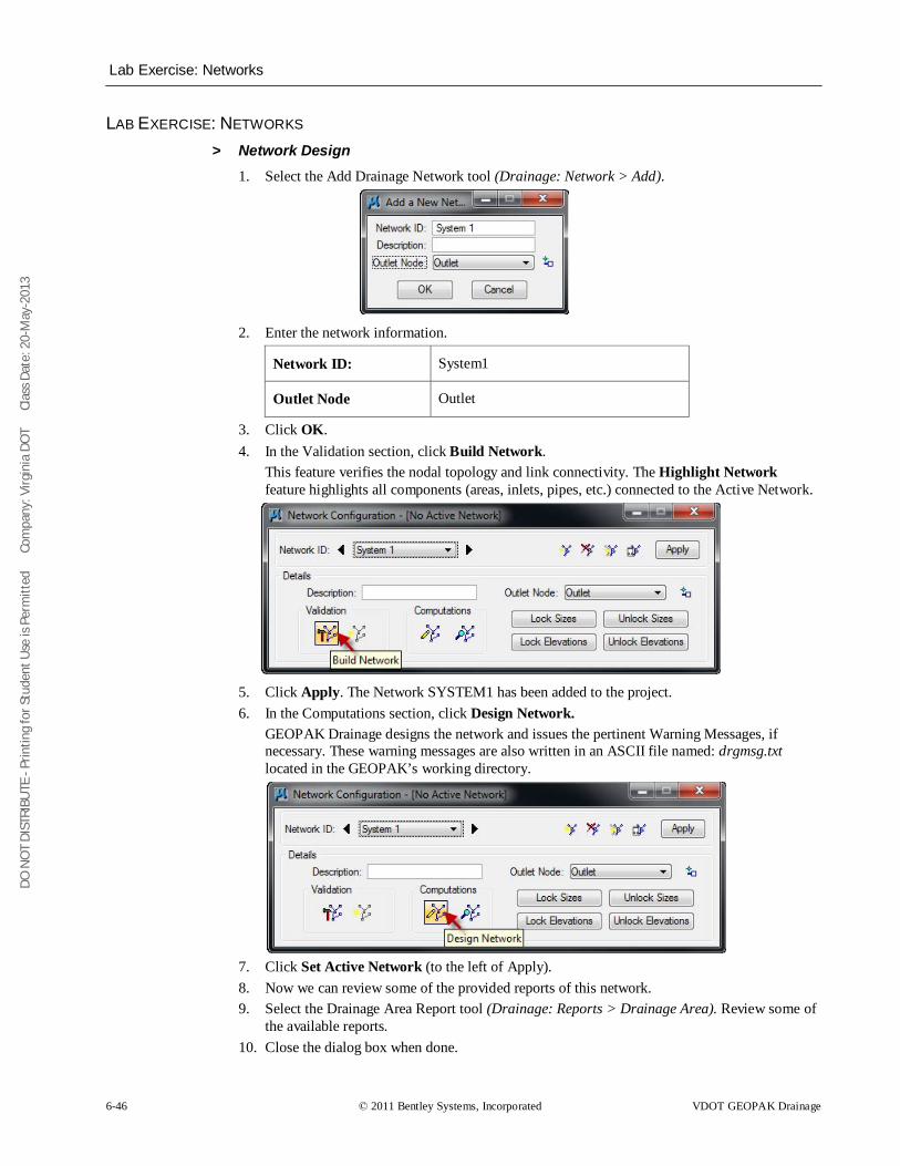
DO N
OT
DIST
RIBU
TE -
Prin
ting
for S
tude
nt U
se is
Per
mitt
ed
Co
mpa
ny: V
irgin
ia D
OT
C
lass
Dat
e: 2
0-M
ay-2
013
Lab Exercise: Networks
6-46 © 2011 Bentley Systems, Incorporated VDOT GEOPAK Drainage
LAB EXERCISE: NETWORKS > Network Design
1. Select the Add Drainage Network tool (Drainage: Network > Add).
2. Enter the network information.
Network ID: System1
Outlet Node Outlet
3. Click OK. 4. In the Validation section, click Build Network.
This feature verifies the nodal topology and link connectivity. The Highlight Network feature highlights all components (areas, inlets, pipes, etc.) connected to the Active Network.
5. Click Apply. The Network SYSTEM1 has been added to the project. 6. In the Computations section, click Design Network.
GEOPAK Drainage designs the network and issues the pertinent Warning Messages, if necessary. These warning messages are also written in an ASCII file named: drgmsg.txt located in the GEOPAK’s working directory.
7. Click Set Active Network (to the left of Apply). 8. Now we can review some of the provided reports of this network. 9. Select the Drainage Area Report tool (Drainage: Reports > Drainage Area). Review some of
the available reports. 10. Close the dialog box when done.
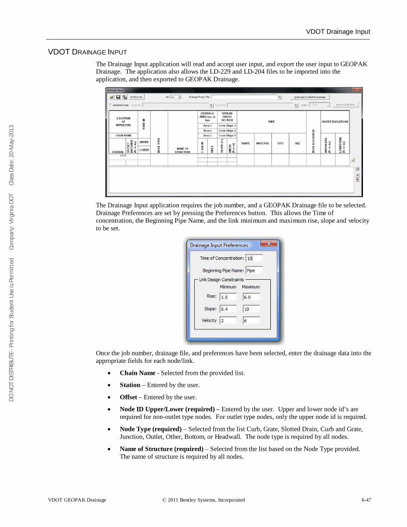
DO N
OT
DIST
RIBU
TE -
Prin
ting
for S
tude
nt U
se is
Per
mitt
ed
Co
mpa
ny: V
irgin
ia D
OT
C
lass
Dat
e: 2
0-M
ay-2
013
VDOT Drainage Input
VDOT GEOPAK Drainage © 2011 Bentley Systems, Incorporated 6-47
VDOT DRAINAGE INPUT The Drainage Input application will read and accept user input, and export the user input to GEOPAK Drainage. The application also allows the LD-229 and LD-204 files to be imported into the application, and then exported to GEOPAK Drainage.
The Drainage Input application requires the job number, and a GEOPAK Drainage file to be selected. Drainage Preferences are set by pressing the Preferences button. This allows the Time of concentration, the Beginning Pipe Name, and the link minimum and maximum rise, slope and velocity to be set.
Once the job number, drainage file, and preferences have been selected, enter the drainage data into the appropriate fields for each node/link.
• Chain Name - Selected from the provided list.
• Station – Entered by the user.
• Offset – Entered by the user.
• Node ID Upper/Lower (required) – Entered by the user. Upper and lower node id’s are required for non-outlet type nodes. For outlet type nodes, only the upper node id is required.
• Node Type (required) – Selected from the list Curb, Grate, Slotted Drain, Curb and Grate, Junction, Outlet, Other, Bottom, or Headwall. The node type is required by all nodes.
• Name of Structure (required) – Selected from the list based on the Node Type provided. The name of structure is required by all nodes.
DO N
OT
DIST
RIBU
TE -
Prin
ting
for S
tude
nt U
se is
Per
mitt
ed
Co
mpa
ny: V
irgin
ia D
OT
C
lass
Dat
e: 2
0-M
ay-2
013
VDOT Drainage Input
6-48 © 2011 Bentley Systems, Incorporated VDOT GEOPAK Drainage
• Drainage Area C Values (required) – Entered by the user for each sub area. The C value is only required by non-outlet type nodes.
• Drainage Area Areas (required) – Entered by the user for each sub area. The drainage area is only required by non-outlet type nodes.
• Spread Cross Section Cross Slope – Entered by the user for each section.
• Spread Cross Section Width – Entered by the user for each section.
• Pipe Shape – Selected from the list Arch, Box, Circular, Ellipse, or Pipe – Arch.
• Pipe Material – Selected from the list based on the pipe shape, Aluminum, Concrete, Plastic, or Steel.
• Pipe Type – Selected from the list based on the pipe shape.
• Pipe Size (required) – Selected from the list based on the pipe shape, pipe material, and pipe type. The pipe size is only required by non-outlet type nodes.
• Node Elevation (required) – Entered by the user. The node elevation is required by all node types.
• Invert Elevations Upper/Lower (required) – Entered by the user. The upper/lower invert elevations are only required by non-outlet type nodes.
Once all of the pertinent data is entered, press the Add button to the right if the data fields to add it to the list. Additional nodes/links can be added to the list as needed. Each lower node must have a matching upper node for the project to be imported.
The project outlet nodes can be stored by entering just the upper node information. No pipe or drainage area information will be used for the outlet nodes. The outlet node elevation is required.
To modify an entry in the list, select the entry in the list. This displays the entry in the entry fields. Make the desired changes. Press the Modify button to make the changes in the list.
The Delete button or the Delete All button will delete the selected entry or all of the entries from the list respectively.
To import the data from the LD-229 and LD-204 spreadsheets, toggle on the Use Ensoft Data toggle. This will activate the required fields. Select the LD229 file and the LD204 file respectively. Select the chain name. Press the Import Ensoft Data button to import the data to the list. The list entries can then be modified to complete any missing data.
Note NOTE: GEOPAK Drainage requires some data that is currently not available from the Ensoft spreadsheets. This data will need to be manually entered.
Once all data has been entered, press the Write Data to GEOPAK Drainage button to import the data to GEOPAK Drainage.
Note The drainage project file (.gdf) must be opened in GEOPAK Drainage prior to pressing the Write Data to GEOPAK Drainage button.
The user has the opportunity to save the dialog settings into a settings file. When the Drainage Input application is opened, it will search the current directory for the settings file. If a settings file is found, the dialog will be populated with the information from the first settings file it finds. If another settings file is desired, the Open Settings File icon on the dialog is used to search for another settings file. Also available on the dialog are a Save Settings and Save Settings to Another File option.
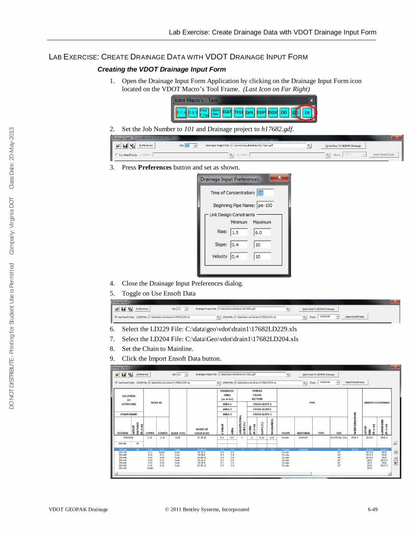
DO N
OT
DIST
RIBU
TE -
Prin
ting
for S
tude
nt U
se is
Per
mitt
ed
Co
mpa
ny: V
irgin
ia D
OT
C
lass
Dat
e: 2
0-M
ay-2
013
Lab Exercise: Create Drainage Data with VDOT Drainage Input Form
VDOT GEOPAK Drainage © 2011 Bentley Systems, Incorporated 6-49
LAB EXERCISE: CREATE DRAINAGE DATA WITH VDOT DRAINAGE INPUT FORM Creating the VDOT Drainage Input Form
1. Open the Drainage Input Form Application by clicking on the Drainage Input Form icon located on the VDOT Macro’s Tool Frame. (Last Icon on Far Right)
2. Set the Job Number to 101 and Drainage project to h17682.gdf.
3. Press Preferences button and set as shown.
4. Close the Drainage Input Preferences dialog. 5. Toggle on Use Ensoft Data
6. Select the LD229 File: C:\data\geo\vdot\drain1\17682LD229.xls 7. Select the LD204 File: C:\data\Geo\vdot\drain1\17682LD204.xls 8. Set the Chain to Mainline. 9. Click the Import Ensoft Data button.
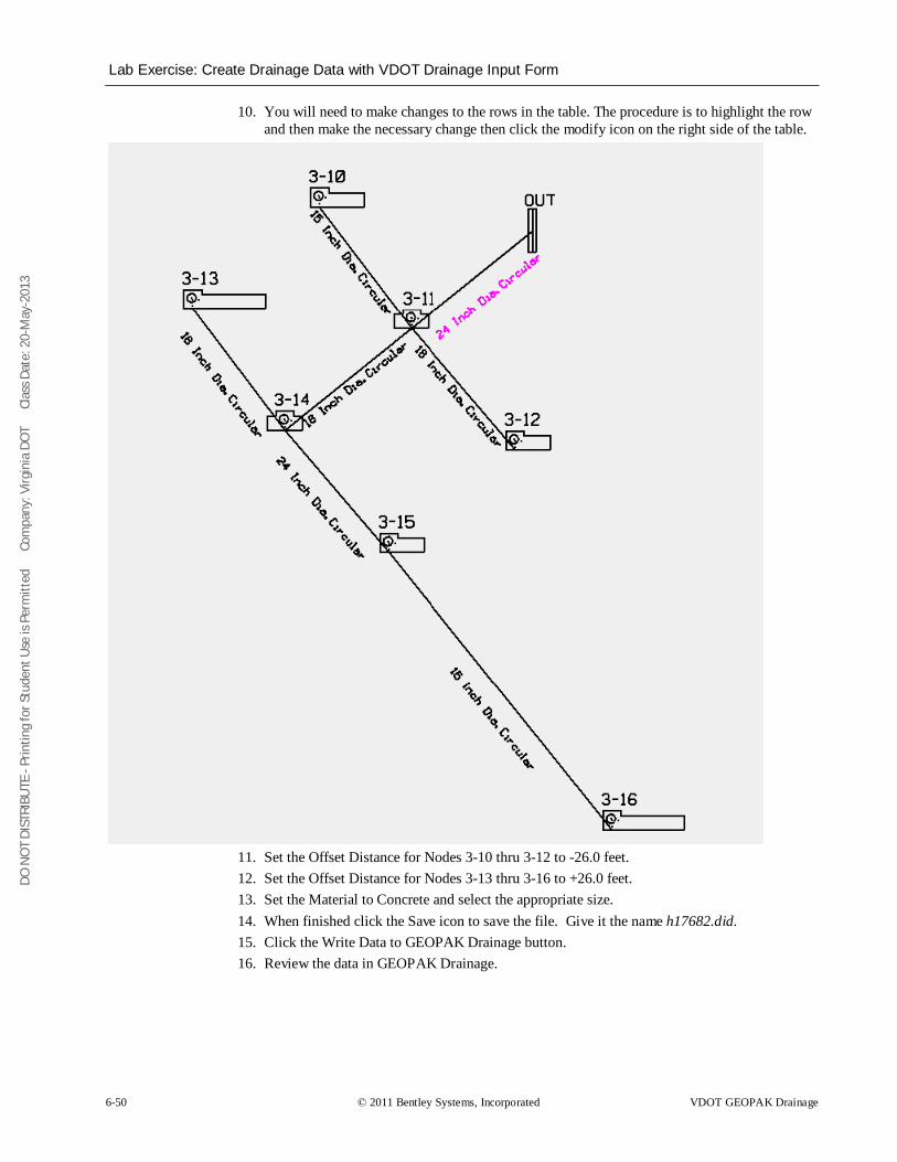
DO N
OT
DIST
RIBU
TE -
Prin
ting
for S
tude
nt U
se is
Per
mitt
ed
Co
mpa
ny: V
irgin
ia D
OT
C
lass
Dat
e: 2
0-M
ay-2
013
Lab Exercise: Create Drainage Data with VDOT Drainage Input Form
6-50 © 2011 Bentley Systems, Incorporated VDOT GEOPAK Drainage
10. You will need to make changes to the rows in the table. The procedure is to highlight the row and then make the necessary change then click the modify icon on the right side of the table.
11. Set the Offset Distance for Nodes 3-10 thru 3-12 to -26.0 feet. 12. Set the Offset Distance for Nodes 3-13 thru 3-16 to +26.0 feet. 13. Set the Material to Concrete and select the appropriate size. 14. When finished click the Save icon to save the file. Give it the name h17682.did. 15. Click the Write Data to GEOPAK Drainage button. 16. Review the data in GEOPAK Drainage.
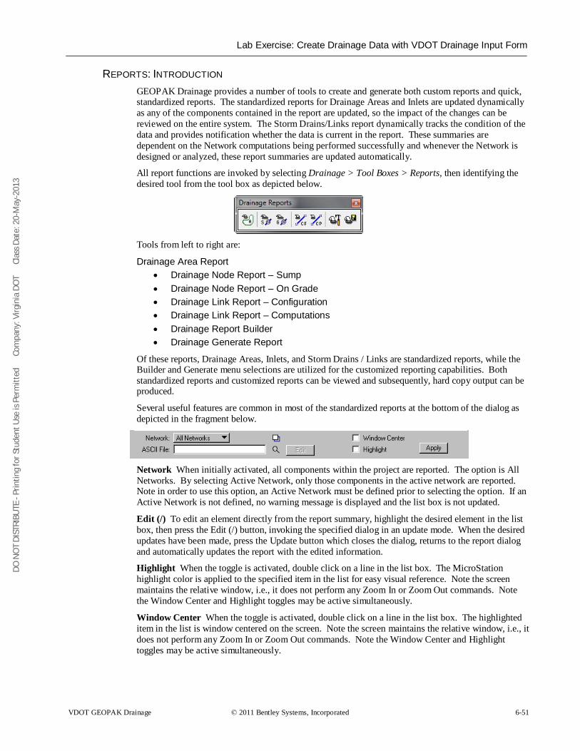
DO N
OT
DIST
RIBU
TE -
Prin
ting
for S
tude
nt U
se is
Per
mitt
ed
Co
mpa
ny: V
irgin
ia D
OT
C
lass
Dat
e: 2
0-M
ay-2
013
Lab Exercise: Create Drainage Data with VDOT Drainage Input Form
VDOT GEOPAK Drainage © 2011 Bentley Systems, Incorporated 6-51
REPORTS: INTRODUCTION GEOPAK Drainage provides a number of tools to create and generate both custom reports and quick, standardized reports. The standardized reports for Drainage Areas and Inlets are updated dynamically as any of the components contained in the report are updated, so the impact of the changes can be reviewed on the entire system. The Storm Drains/Links report dynamically tracks the condition of the data and provides notification whether the data is current in the report. These summaries are dependent on the Network computations being performed successfully and whenever the Network is designed or analyzed, these report summaries are updated automatically.
All report functions are invoked by selecting Drainage > Tool Boxes > Reports, then identifying the desired tool from the tool box as depicted below.
Tools from left to right are:
Drainage Area Report • Drainage Node Report – Sump • Drainage Node Report – On Grade • Drainage Link Report – Configuration • Drainage Link Report – Computations • Drainage Report Builder • Drainage Generate Report
Of these reports, Drainage Areas, Inlets, and Storm Drains / Links are standardized reports, while the Builder and Generate menu selections are utilized for the customized reporting capabilities. Both standardized reports and customized reports can be viewed and subsequently, hard copy output can be produced.
Several useful features are common in most of the standardized reports at the bottom of the dialog as depicted in the fragment below.
Network When initially activated, all components within the project are reported. The option is All Networks. By selecting Active Network, only those components in the active network are reported. Note in order to use this option, an Active Network must be defined prior to selecting the option. If an Active Network is not defined, no warning message is displayed and the list box is not updated.
Edit (/) To edit an element directly from the report summary, highlight the desired element in the list box, then press the Edit (/) button, invoking the specified dialog in an update mode. When the desired updates have been made, press the Update button which closes the dialog, returns to the report dialog and automatically updates the report with the edited information.
Highlight When the toggle is activated, double click on a line in the list box. The MicroStation highlight color is applied to the specified item in the list for easy visual reference. Note the screen maintains the relative window, i.e., it does not perform any Zoom In or Zoom Out commands. Note the Window Center and Highlight toggles may be active simultaneously.
Window Center When the toggle is activated, double click on a line in the list box. The highlighted item in the list is window centered on the screen. Note the screen maintains the relative window, i.e., it does not perform any Zoom In or Zoom Out commands. Note the Window Center and Highlight toggles may be active simultaneously.
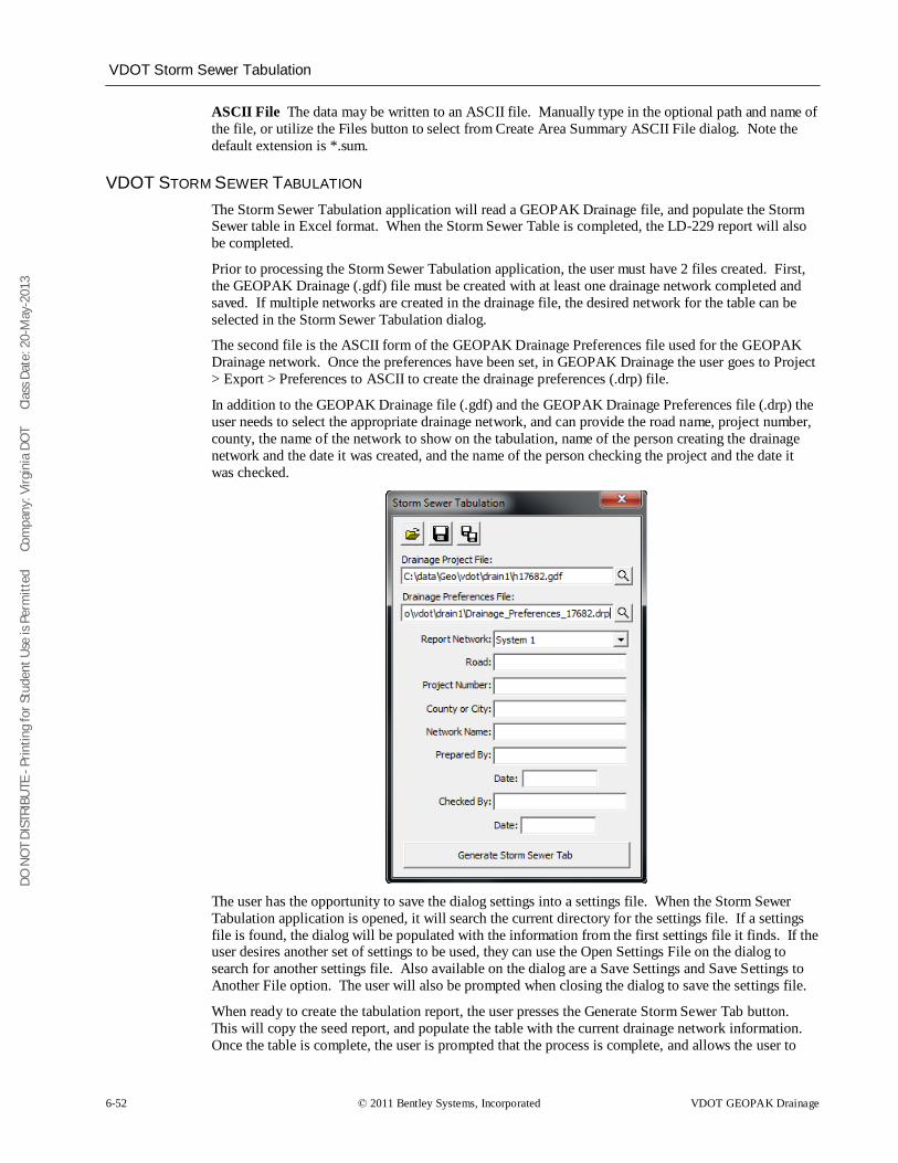
DO N
OT
DIST
RIBU
TE -
Prin
ting
for S
tude
nt U
se is
Per
mitt
ed
Co
mpa
ny: V
irgin
ia D
OT
C
lass
Dat
e: 2
0-M
ay-2
013
VDOT Storm Sewer Tabulation
6-52 © 2011 Bentley Systems, Incorporated VDOT GEOPAK Drainage
ASCII File The data may be written to an ASCII file. Manually type in the optional path and name of the file, or utilize the Files button to select from Create Area Summary ASCII File dialog. Note the default extension is *.sum.
VDOT STORM SEWER TABULATION The Storm Sewer Tabulation application will read a GEOPAK Drainage file, and populate the Storm Sewer table in Excel format. When the Storm Sewer Table is completed, the LD-229 report will also be completed.
Prior to processing the Storm Sewer Tabulation application, the user must have 2 files created. First, the GEOPAK Drainage (.gdf) file must be created with at least one drainage network completed and saved. If multiple networks are created in the drainage file, the desired network for the table can be selected in the Storm Sewer Tabulation dialog.
The second file is the ASCII form of the GEOPAK Drainage Preferences file used for the GEOPAK Drainage network. Once the preferences have been set, in GEOPAK Drainage the user goes to Project > Export > Preferences to ASCII to create the drainage preferences (.drp) file.
In addition to the GEOPAK Drainage file (.gdf) and the GEOPAK Drainage Preferences file (.drp) the user needs to select the appropriate drainage network, and can provide the road name, project number, county, the name of the network to show on the tabulation, name of the person creating the drainage network and the date it was created, and the name of the person checking the project and the date it was checked.
The user has the opportunity to save the dialog settings into a settings file. When the Storm Sewer Tabulation application is opened, it will search the current directory for the settings file. If a settings file is found, the dialog will be populated with the information from the first settings file it finds. If the user desires another set of settings to be used, they can use the Open Settings File on the dialog to search for another settings file. Also available on the dialog are a Save Settings and Save Settings to Another File option. The user will also be prompted when closing the dialog to save the settings file.
When ready to create the tabulation report, the user presses the Generate Storm Sewer Tab button. This will copy the seed report, and populate the table with the current drainage network information. Once the table is complete, the user is prompted that the process is complete, and allows the user to
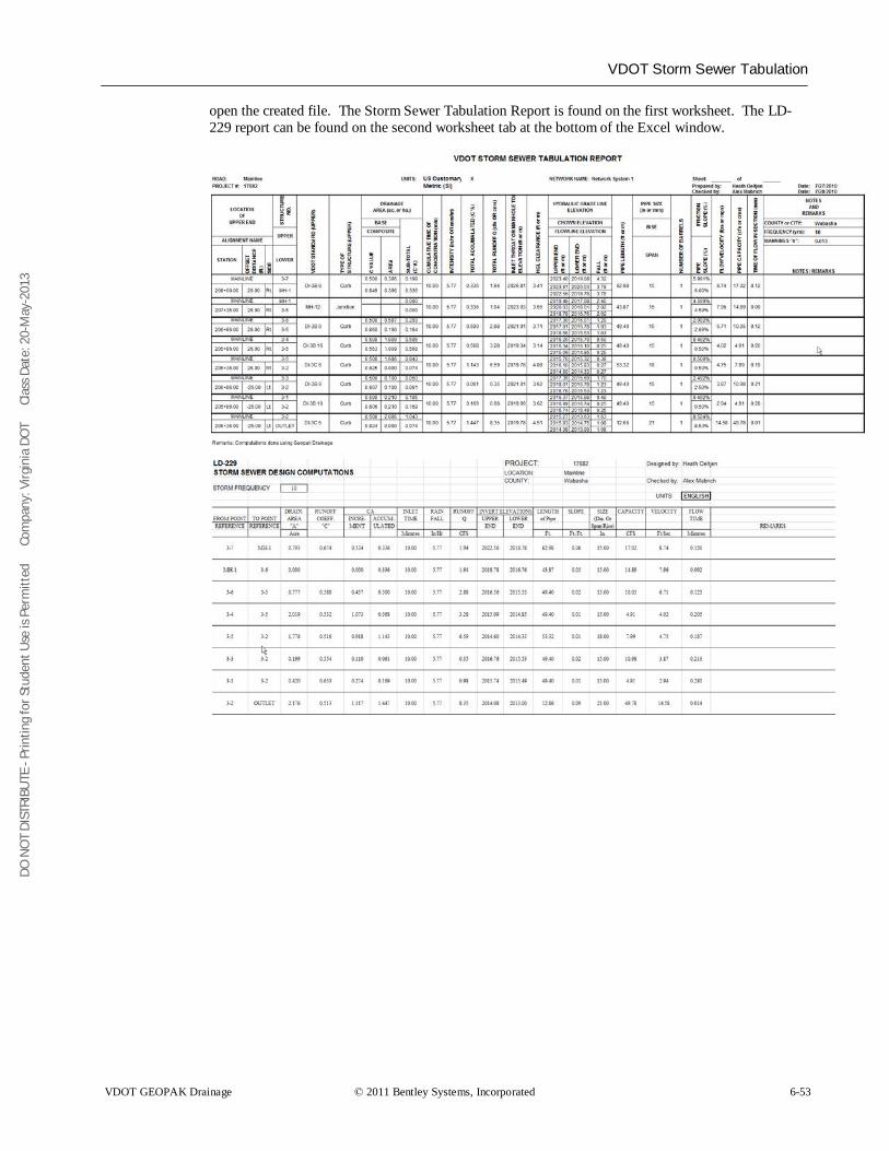
DO N
OT
DIST
RIBU
TE -
Prin
ting
for S
tude
nt U
se is
Per
mitt
ed
Co
mpa
ny: V
irgin
ia D
OT
C
lass
Dat
e: 2
0-M
ay-2
013
VDOT Storm Sewer Tabulation
VDOT GEOPAK Drainage © 2011 Bentley Systems, Incorporated 6-53
open the created file. The Storm Sewer Tabulation Report is found on the first worksheet. The LD-229 report can be found on the second worksheet tab at the bottom of the Excel window.
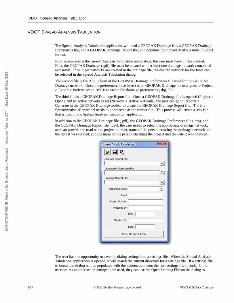
DO N
OT
DIST
RIBU
TE -
Prin
ting
for S
tude
nt U
se is
Per
mitt
ed
Co
mpa
ny: V
irgin
ia D
OT
C
lass
Dat
e: 2
0-M
ay-2
013
VDOT Spread Analysis Tabulation
6-54 © 2011 Bentley Systems, Incorporated VDOT GEOPAK Drainage
VDOT SPREAD ANALYSIS TABULATION
The Spread Analysis Tabulation application will read a GEOPAK Drainage file, a GEOPAK Drainage Preferences file, and a GEOPAK Drainage Report file, and populate the Spread Analysis table in Excel format.
Prior to processing the Spread Analysis Tabulation application, the user must have 3 files created. First, the GEOPAK Drainage (.gdf) file must be created with at least one drainage network completed and saved. If multiple networks are created in the drainage file, the desired network for the table can be selected in the Spread Analysis Tabulation dialog.
The second file is the ASCII form of the GEOPAK Drainage Preferences file used for the GEOPAK Drainage network. Once the preferences have been set, in GEOPAK Drainage the user goes to Project > Export > Preferences to ASCII to create the drainage preferences (.drp) file.
The third file is a GEOPAK Drainage Report file. Once a GEOPAK Drainage file is opened (Project > Open), and an active network is set (Network > Active Network), the user can go to Reports > Generate in the GEOPAK Drainage toolbar to create the GEOPAK Drainage Report file. The file SpreadAnalysisReport.drf needs to be selected as the format file. This process will create a .csv file that is used in the Spread Analysis Tabulation application.
In addition to the GEOPAK Drainage file (.gdf), the GEOPAK Drainage Preferences file (.drp), and the GEOPAK Drainage Report file (.csv), the user needs to select the appropriate drainage network, and can provide the road name, project number, name of the person creating the drainage network and the date it was created, and the name of the person checking the project and the date it was checked.
The user has the opportunity to save the dialog settings into a settings file. When the Spread Analysis Tabulation application is opened, it will search the current directory for a settings file. If a settings file is found, the dialog will be populated with the information from the first settings file it finds. If the user desires another set of settings to be used, they can use the Open Settings File on the dialog to
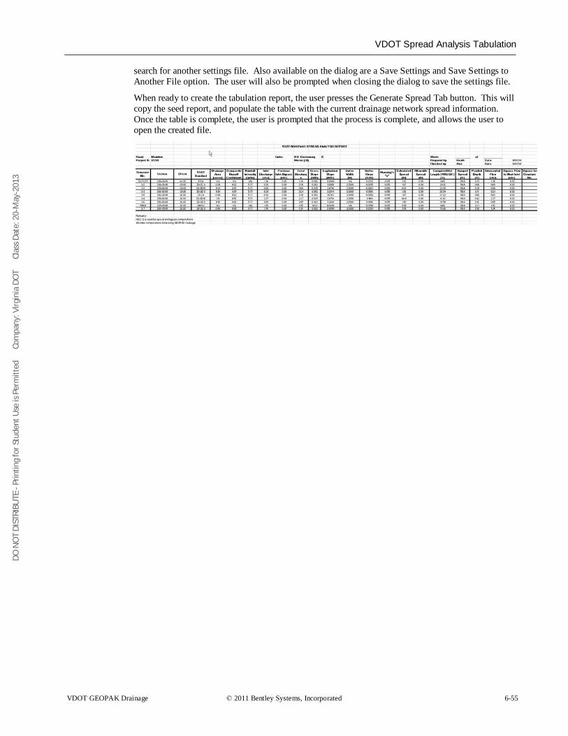
DO N
OT
DIST
RIBU
TE -
Prin
ting
for S
tude
nt U
se is
Per
mitt
ed
Co
mpa
ny: V
irgin
ia D
OT
C
lass
Dat
e: 2
0-M
ay-2
013
VDOT Spread Analysis Tabulation
VDOT GEOPAK Drainage © 2011 Bentley Systems, Incorporated 6-55
search for another settings file. Also available on the dialog are a Save Settings and Save Settings to Another File option. The user will also be prompted when closing the dialog to save the settings file.
When ready to create the tabulation report, the user presses the Generate Spread Tab button. This will copy the seed report, and populate the table with the current drainage network spread information. Once the table is complete, the user is prompted that the process is complete, and allows the user to open the created file.
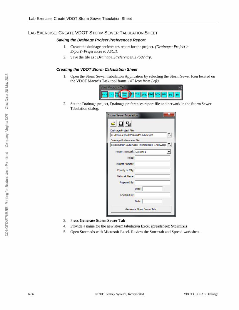
DO N
OT
DIST
RIBU
TE -
Prin
ting
for S
tude
nt U
se is
Per
mitt
ed
Co
mpa
ny: V
irgin
ia D
OT
C
lass
Dat
e: 2
0-M
ay-2
013
Lab Exercise: Create VDOT Storm Sewer Tabulation Sheet
6-56 © 2011 Bentley Systems, Incorporated VDOT GEOPAK Drainage
LAB EXERCISE: CREATE VDOT STORM SEWER TABULATION SHEET Saving the Drainage Project Preferences Report
1. Create the drainage preferences report for the project. (Drainage: Project > Export>Preferences to ASCII.
2. Save the file as : Drainage_Preferences_17682.drp.
Creating the VDOT Storm Calculation Sheet 1. Open the Storm Sewer Tabulation Application by selecting the Storm Sewer Icon located on
the VDOT Macro’s Task tool frame. (4th
Icon from Left)
2. Set the Drainage project, Drainage preferences report file and network in the Storm Sewer Tabulation dialog.
3. Press Generate Storm Sewer Tab 4. Provide a name for the new storm tabulation Excel spreadsheet: Storm.xls 5. Open Storm.xls with Microsoft Excel. Review the Stormtab and Spread worksheet.
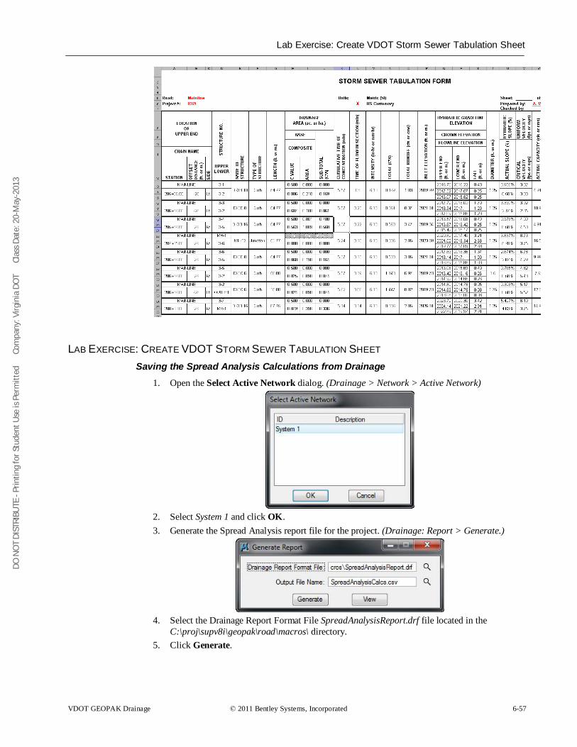
DO N
OT
DIST
RIBU
TE -
Prin
ting
for S
tude
nt U
se is
Per
mitt
ed
Co
mpa
ny: V
irgin
ia D
OT
C
lass
Dat
e: 2
0-M
ay-2
013
Lab Exercise: Create VDOT Storm Sewer Tabulation Sheet
VDOT GEOPAK Drainage © 2011 Bentley Systems, Incorporated 6-57
LAB EXERCISE: CREATE VDOT STORM SEWER TABULATION SHEET Saving the Spread Analysis Calculations from Drainage
1. Open the Select Active Network dialog. (Drainage > Network > Active Network)
2. Select System 1 and click OK. 3. Generate the Spread Analysis report file for the project. (Drainage: Report > Generate.)
4. Select the Drainage Report Format File SpreadAnalysisReport.drf file located in the
C:\proj\supv8i\geopak\road\macros\ directory. 5. Click Generate.
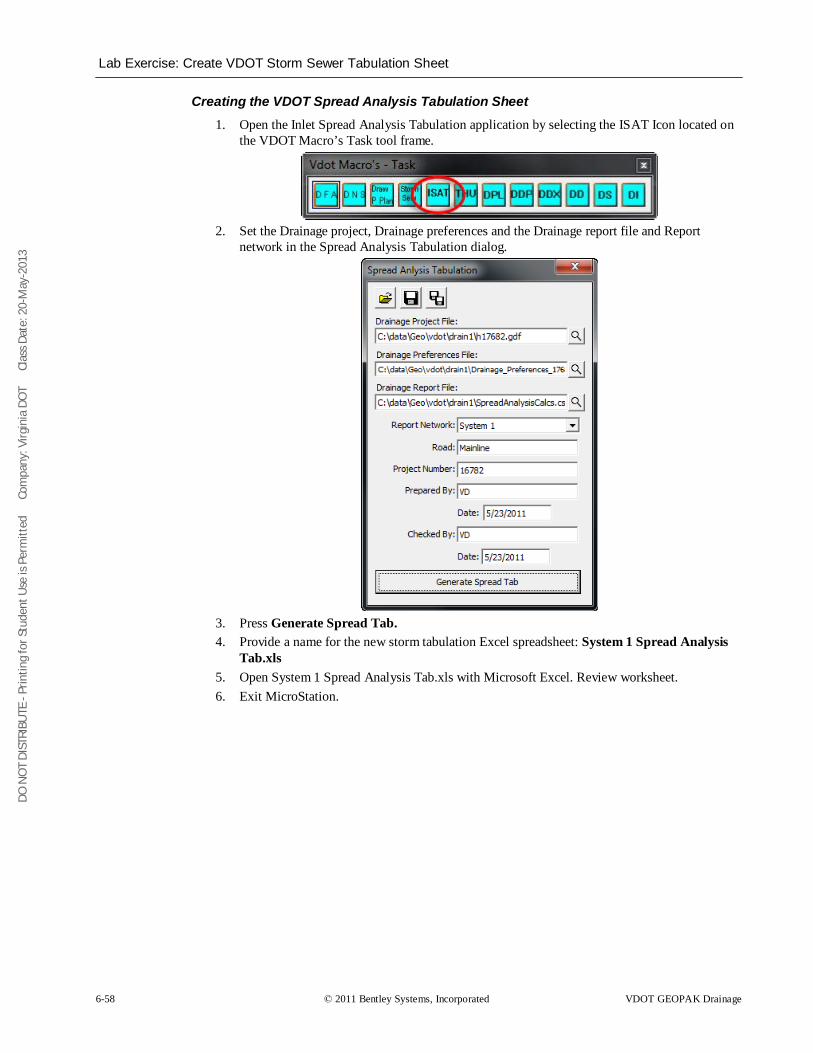
DO N
OT
DIST
RIBU
TE -
Prin
ting
for S
tude
nt U
se is
Per
mitt
ed
Co
mpa
ny: V
irgin
ia D
OT
C
lass
Dat
e: 2
0-M
ay-2
013
Lab Exercise: Create VDOT Storm Sewer Tabulation Sheet
6-58 © 2011 Bentley Systems, Incorporated VDOT GEOPAK Drainage
Creating the VDOT Spread Analysis Tabulation Sheet 1. Open the Inlet Spread Analysis Tabulation application by selecting the ISAT Icon located on
the VDOT Macro’s Task tool frame.
2. Set the Drainage project, Drainage preferences and the Drainage report file and Report
network in the Spread Analysis Tabulation dialog.
3. Press Generate Spread Tab. 4. Provide a name for the new storm tabulation Excel spreadsheet: System 1 Spread Analysis
Tab.xls 5. Open System 1 Spread Analysis Tab.xls with Microsoft Excel. Review worksheet. 6. Exit MicroStation.
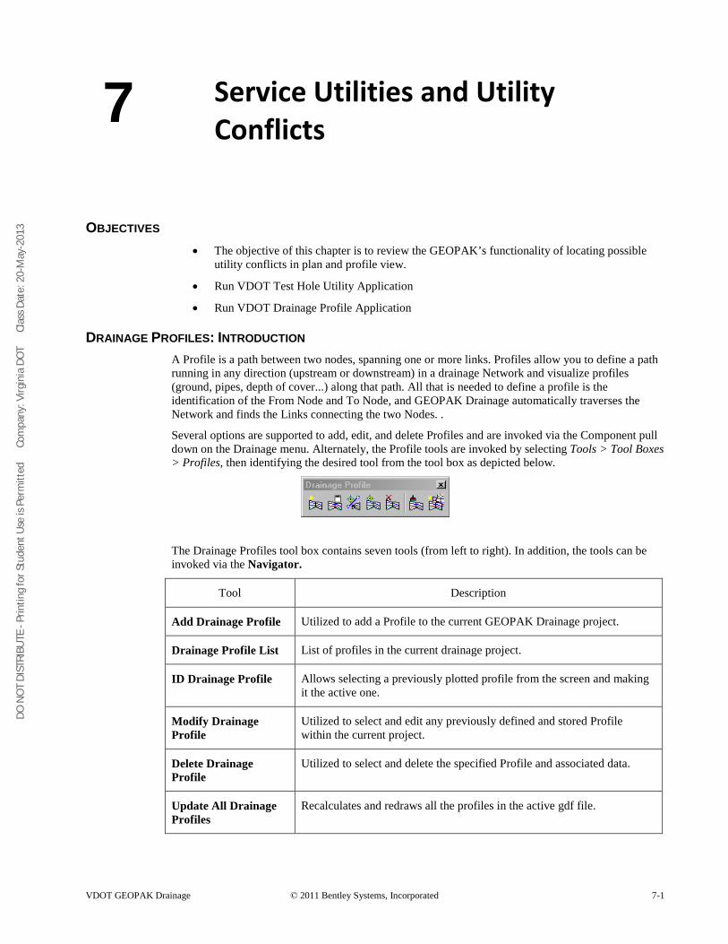
DO N
OT
DIST
RIBU
TE -
Prin
ting
for S
tude
nt U
se is
Per
mitt
ed
Co
mpa
ny: V
irgin
ia D
OT
C
lass
Dat
e: 2
0-M
ay-2
013
VDOT GEOPAK Drainage © 2011 Bentley Systems, Incorporated 7-1
Service Utilities and Utility Conflicts
OBJECTIVES • The objective of this chapter is to review the GEOPAK’s functionality of locating possible
utility conflicts in plan and profile view.
• Run VDOT Test Hole Utility Application
• Run VDOT Drainage Profile Application
DRAINAGE PROFILES: INTRODUCTION A Profile is a path between two nodes, spanning one or more links. Profiles allow you to define a path running in any direction (upstream or downstream) in a drainage Network and visualize profiles (ground, pipes, depth of cover...) along that path. All that is needed to define a profile is the identification of the From Node and To Node, and GEOPAK Drainage automatically traverses the Network and finds the Links connecting the two Nodes. .
Several options are supported to add, edit, and delete Profiles and are invoked via the Component pull down on the Drainage menu. Alternately, the Profile tools are invoked by selecting Tools > Tool Boxes > Profiles, then identifying the desired tool from the tool box as depicted below.
The Drainage Profiles tool box contains seven tools (from left to right). In addition, the tools can be invoked via the Navigator.
Tool Description
Add Drainage Profile Utilized to add a Profile to the current GEOPAK Drainage project.
Drainage Profile List List of profiles in the current drainage project.
ID Drainage Profile Allows selecting a previously plotted profile from the screen and making it the active one.
Modify Drainage Profile
Utilized to select and edit any previously defined and stored Profile within the current project.
Delete Drainage Profile
Utilized to select and delete the specified Profile and associated data.
Update All Drainage Profiles
Recalculates and redraws all the profiles in the active gdf file.
7
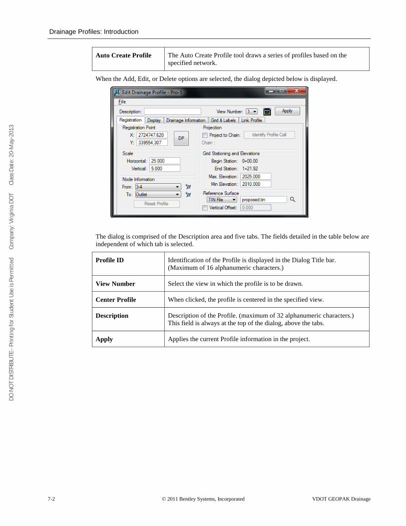
DO N
OT
DIST
RIBU
TE -
Prin
ting
for S
tude
nt U
se is
Per
mitt
ed
Co
mpa
ny: V
irgin
ia D
OT
C
lass
Dat
e: 2
0-M
ay-2
013
Drainage Profiles: Introduction
7-2 © 2011 Bentley Systems, Incorporated VDOT GEOPAK Drainage
Auto Create Profile The Auto Create Profile tool draws a series of profiles based on the specified network.
When the Add, Edit, or Delete options are selected, the dialog depicted below is displayed.
The dialog is comprised of the Description area and five tabs. The fields detailed in the table below are independent of which tab is selected.
Profile ID Identification of the Profile is displayed in the Dialog Title bar. (Maximum of 16 alphanumeric characters.)
View Number Select the view in which the profile is to be drawn.
Center Profile When clicked, the profile is centered in the specified view.
Description Description of the Profile. (maximum of 32 alphanumeric characters.) This field is always at the top of the dialog, above the tabs.
Apply Applies the current Profile information in the project.
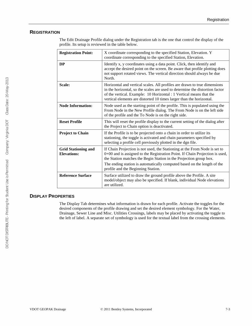
DO N
OT
DIST
RIBU
TE -
Prin
ting
for S
tude
nt U
se is
Per
mitt
ed
Co
mpa
ny: V
irgin
ia D
OT
C
lass
Dat
e: 2
0-M
ay-2
013
Registration
VDOT GEOPAK Drainage © 2011 Bentley Systems, Incorporated 7-3
REGISTRATION The Edit Drainage Profile dialog under the Registration tab is the one that control the display of the profile. Its setup is reviewed in the table below.
Registration Point: X coordinate corresponding to the specified Station, Elevation. Y coordinate corresponding to the specified Station, Elevation.
DP Identify x, y coordinates using a data point. Click, then identify and accept the desired point on the screen. Be aware that profile plotting does not support rotated views. The vertical direction should always be due North.
Scale: Horizontal and vertical scales. All profiles are drawn to true dimensions in the horizontal, so the scales are used to determine the distortion factor of the vertical. Example: 10 Horizontal : 1 Vertical means that the vertical elements are distorted 10 times larger than the horizontal.
Node Information: Node used as the starting point of the profile. This is populated using the From Node in the New Profile dialog. The From Node is on the left side of the profile and the To Node is on the right side.
Reset Profile This will reset the profile display to the current setting of the dialog after the Project to Chain option is deactivated.
Project to Chain If the Profile is to be projected onto a chain in order to utilize its stationing, the toggle is activated and chain parameters specified by selecting a profile cell previously plotted in the dgn file.
Grid Stationing and Elevations:
If Chain Projection is not used, the Stationing at the From Node is set to 0+00 and is assigned to the Registration Point. If Chain Projection is used, the Station matches the Begin Station in the Projection group box. The ending station is automatically computed based on the length of the profile and the Beginning Station.
Reference Surface Surface utilized to draw the ground profile above the Profile. A site model/object may also be specified. If blank, individual Node elevations are utilized.
DISPLAY PROPERTIES The Display Tab determines what information is drawn for each profile. Activate the toggles for the desired components of the profile drawing and set the desired element symbology. For the Water, Drainage, Sewer Line and Misc. Utilities Crossings, labels may be placed by activating the toggle to the left of label. A separate set of symbology is used for the textual label from the crossing elements.

DO N
OT
DIST
RIBU
TE -
Prin
ting
for S
tude
nt U
se is
Per
mitt
ed
Co
mpa
ny: V
irgin
ia D
OT
C
lass
Dat
e: 2
0-M
ay-2
013
Drainage Information
7-4 © 2011 Bentley Systems, Incorporated VDOT GEOPAK Drainage
DRAINAGE INFORMATION Other information from the drainage GDF file may be optionally drawn. This information is generated after the design or analysis of the network. Simply activate the toggle to the left of the desired drainage information, and set the symbology.
GRID AND LABELS A variety of Grid and labels options are supported to enable the user to customize the profile drawings. Six Grid & Labels options are listed on the left side of the dialog. To activate an option, double click to fill the option box to the left. Double click again to turn off, which ghosts the right side of the dialog.
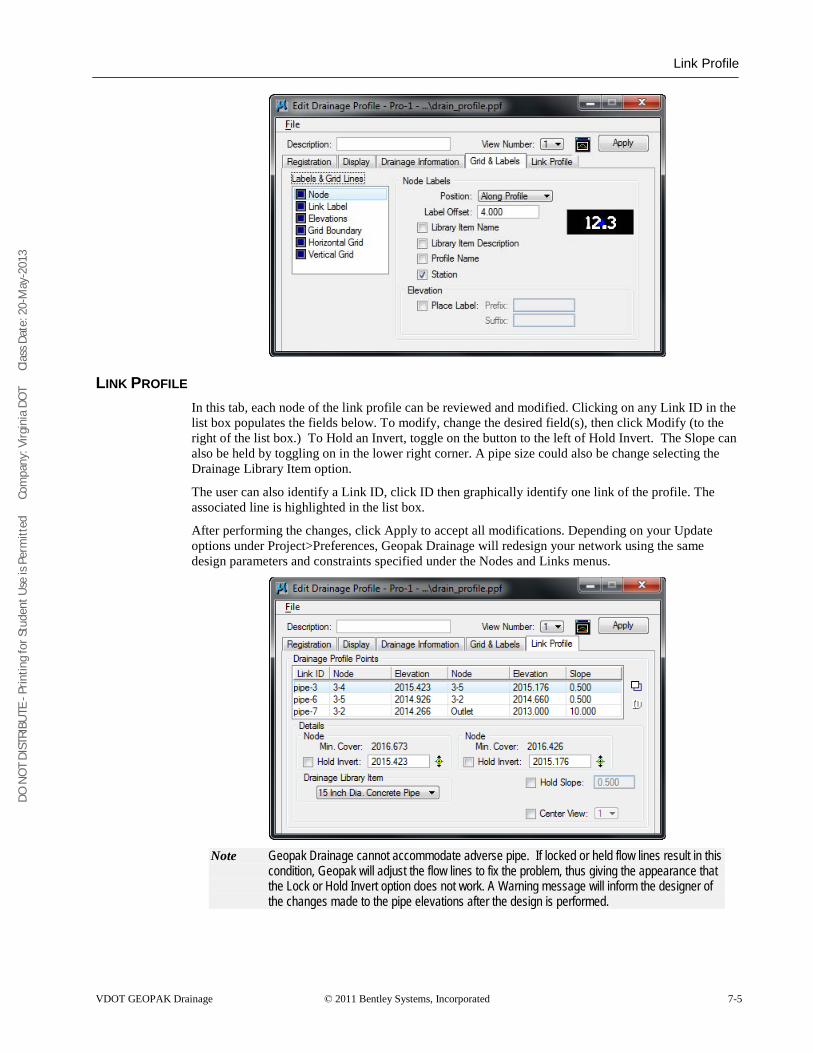
DO N
OT
DIST
RIBU
TE -
Prin
ting
for S
tude
nt U
se is
Per
mitt
ed
Co
mpa
ny: V
irgin
ia D
OT
C
lass
Dat
e: 2
0-M
ay-2
013
Link Profile
VDOT GEOPAK Drainage © 2011 Bentley Systems, Incorporated 7-5
LINK PROFILE In this tab, each node of the link profile can be reviewed and modified. Clicking on any Link ID in the list box populates the fields below. To modify, change the desired field(s), then click Modify (to the right of the list box.) To Hold an Invert, toggle on the button to the left of Hold Invert. The Slope can also be held by toggling on in the lower right corner. A pipe size could also be change selecting the Drainage Library Item option.
The user can also identify a Link ID, click ID then graphically identify one link of the profile. The associated line is highlighted in the list box.
After performing the changes, click Apply to accept all modifications. Depending on your Update options under Project>Preferences, Geopak Drainage will redesign your network using the same design parameters and constraints specified under the Nodes and Links menus.
Note Geopak Drainage cannot accommodate adverse pipe. If locked or held flow lines result in this
condition, Geopak will adjust the flow lines to fix the problem, thus giving the appearance that the Lock or Hold Invert option does not work. A Warning message will inform the designer of the changes made to the pipe elevations after the design is performed.
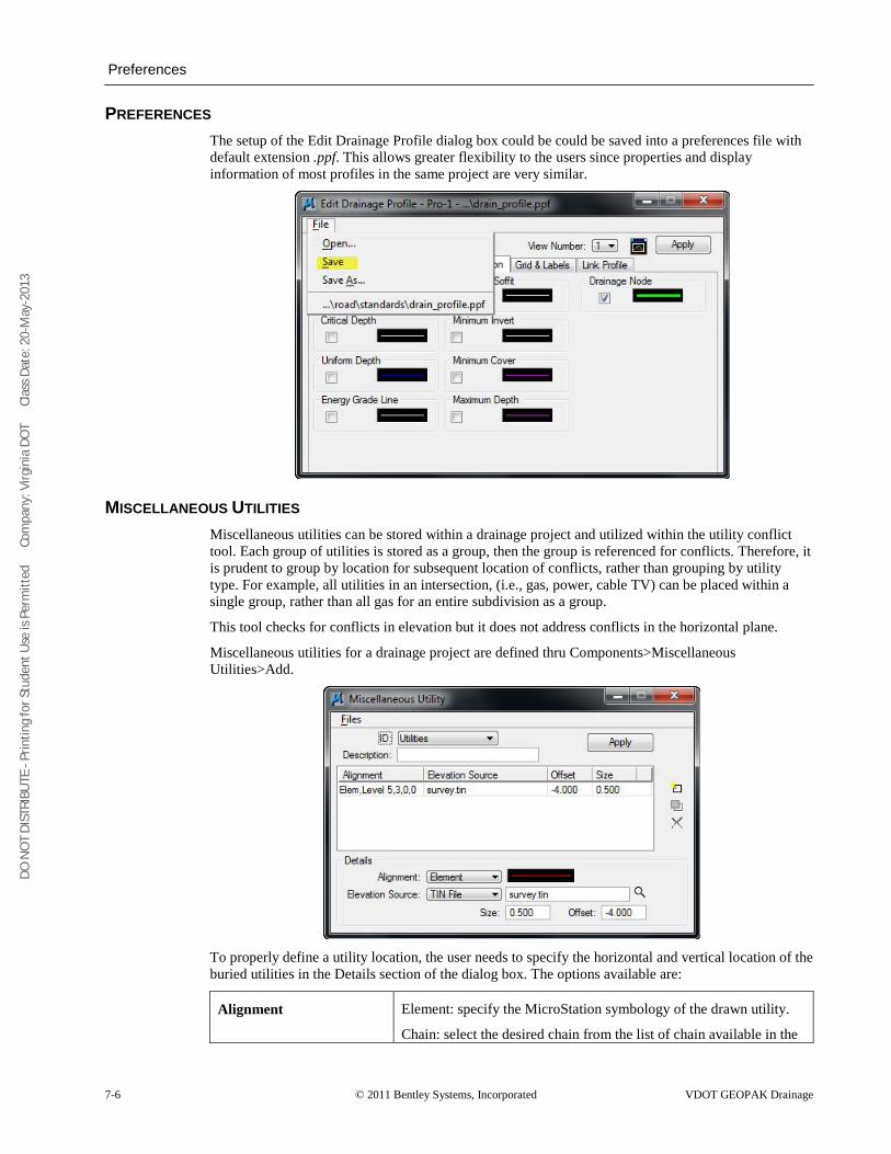
DO N
OT
DIST
RIBU
TE -
Prin
ting
for S
tude
nt U
se is
Per
mitt
ed
Co
mpa
ny: V
irgin
ia D
OT
C
lass
Dat
e: 2
0-M
ay-2
013
Preferences
7-6 © 2011 Bentley Systems, Incorporated VDOT GEOPAK Drainage
PREFERENCES The setup of the Edit Drainage Profile dialog box could be could be saved into a preferences file with default extension .ppf. This allows greater flexibility to the users since properties and display information of most profiles in the same project are very similar.
MISCELLANEOUS UTILITIES Miscellaneous utilities can be stored within a drainage project and utilized within the utility conflict tool. Each group of utilities is stored as a group, then the group is referenced for conflicts. Therefore, it is prudent to group by location for subsequent location of conflicts, rather than grouping by utility type. For example, all utilities in an intersection, (i.e., gas, power, cable TV) can be placed within a single group, rather than all gas for an entire subdivision as a group.
This tool checks for conflicts in elevation but it does not address conflicts in the horizontal plane.
Miscellaneous utilities for a drainage project are defined thru Components>Miscellaneous Utilities>Add.
To properly define a utility location, the user needs to specify the horizontal and vertical location of the buried utilities in the Details section of the dialog box. The options available are:
Alignment Element: specify the MicroStation symbology of the drawn utility.
Chain: select the desired chain from the list of chain available in the
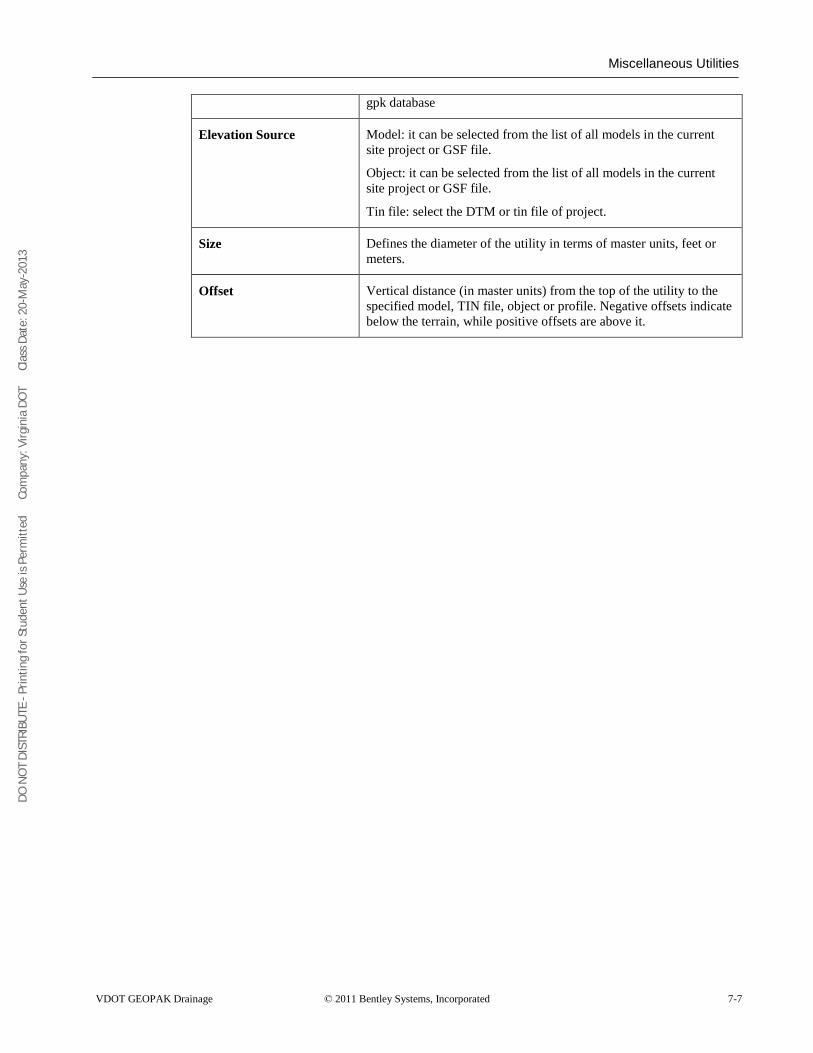
DO N
OT
DIST
RIBU
TE -
Prin
ting
for S
tude
nt U
se is
Per
mitt
ed
Co
mpa
ny: V
irgin
ia D
OT
C
lass
Dat
e: 2
0-M
ay-2
013
Miscellaneous Utilities
VDOT GEOPAK Drainage © 2011 Bentley Systems, Incorporated 7-7
gpk database
Elevation Source Model: it can be selected from the list of all models in the current site project or GSF file.
Object: it can be selected from the list of all models in the current site project or GSF file.
Tin file: select the DTM or tin file of project.
Size Defines the diameter of the utility in terms of master units, feet or meters.
Offset Vertical distance (in master units) from the top of the utility to the specified model, TIN file, object or profile. Negative offsets indicate below the terrain, while positive offsets are above it.
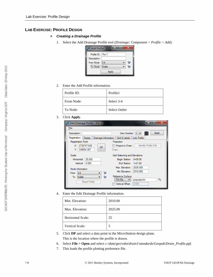
DO N
OT
DIST
RIBU
TE -
Prin
ting
for S
tude
nt U
se is
Per
mitt
ed
Co
mpa
ny: V
irgin
ia D
OT
C
lass
Dat
e: 2
0-M
ay-2
013
Lab Exercise: Profile Design
7-8 © 2011 Bentley Systems, Incorporated VDOT GEOPAK Drainage
LAB EXERCISE: PROFILE DESIGN > Creating a Drainage Profile
1. Select the Add Drainage Profile tool (Drainage: Component > Profile > Add).
2. Enter the Add Profile information.
Profile ID: Profile1
From Node: Select 3-4
To Node: Select Outlet
3. Click Apply.
4. Enter the Edit Drainage Profile information.
Min. Elevation: 2010.00
Max. Elevation: 2025.00
Horizontal Scale: 25
Vertical Scale: 5
5. Click DP and select a data point in the MicroStation design plane. This is the location where the profile is drawn.
6. Select File > Open and select c:\data\geo\vdot\drain1\standards\Geopak\Drain_Profile.ppf. 7. This loads the profile plotting preference file.
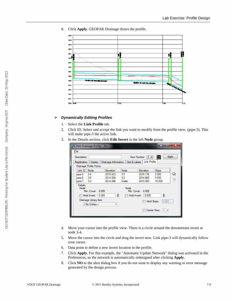
DO N
OT
DIST
RIBU
TE -
Prin
ting
for S
tude
nt U
se is
Per
mitt
ed
Co
mpa
ny: V
irgin
ia D
OT
C
lass
Dat
e: 2
0-M
ay-2
013
Lab Exercise: Profile Design
VDOT GEOPAK Drainage © 2011 Bentley Systems, Incorporated 7-9
8. Click Apply. GEOPAK Drainage draws the profile.
> Dynamically Editing Profiles 1. Select the Link Profile tab. 2. Click ID. Select and accept the link you want to modify from the profile view. (pipe-3). This
will make pipe-3 the active link. 3. In the Details section, click Edit Invert in the left Node group.
4. Move your cursor into the profile view. There is a circle around the downstream invert at node 3-4.
5. Move the cursor into the circle and drag the invert now. Link pipe-3 will dynamically follow your cursor.
6. Data point to define a new invert location in the profile. 7. Click Apply. For this example, the "Automatic Update Network" dialog was activated in the
Preferences, so the network is automatically redesigned after clicking Apply. 8. Click NO to the alert dialog box if you do not want to display any warning or error message
generated by the design process.
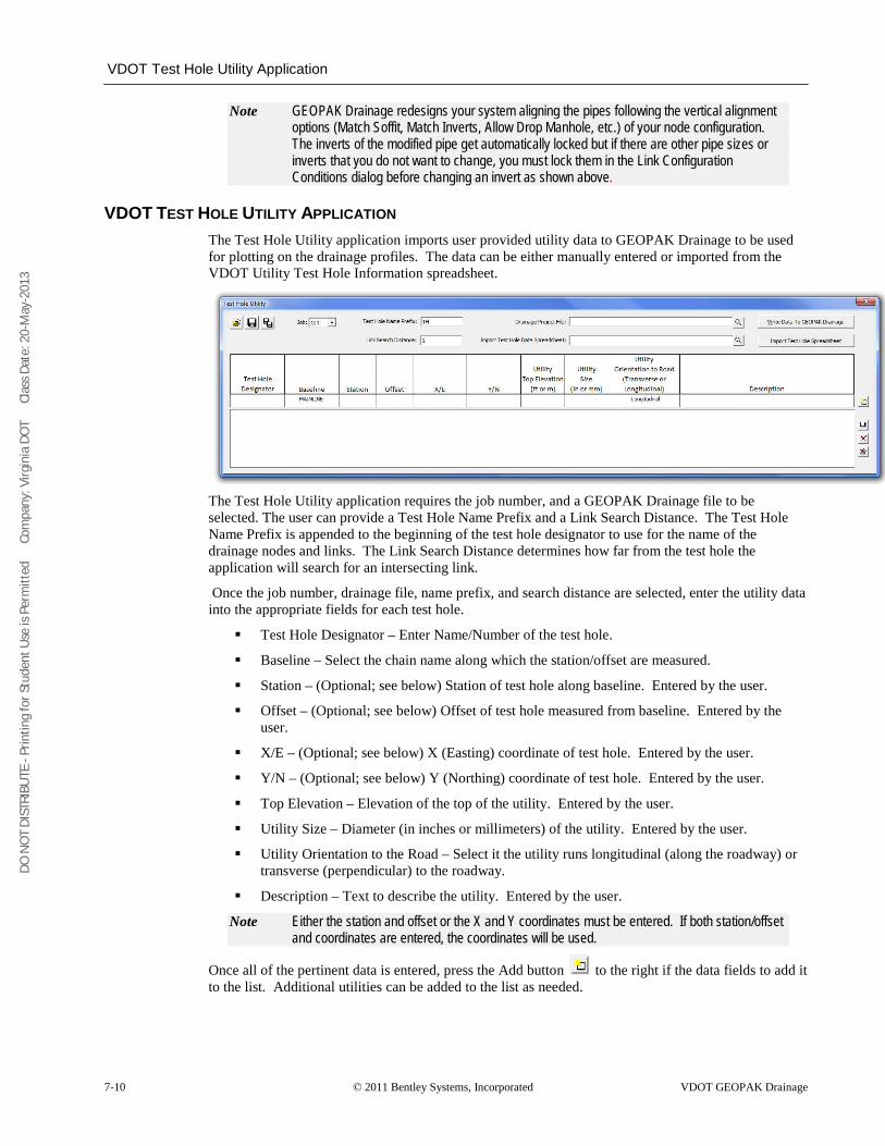
DO N
OT
DIST
RIBU
TE -
Prin
ting
for S
tude
nt U
se is
Per
mitt
ed
Co
mpa
ny: V
irgin
ia D
OT
C
lass
Dat
e: 2
0-M
ay-2
013
VDOT Test Hole Utility Application
7-10 © 2011 Bentley Systems, Incorporated VDOT GEOPAK Drainage
Note GEOPAK Drainage redesigns your system aligning the pipes following the vertical alignment options (Match Soffit, Match Inverts, Allow Drop Manhole, etc.) of your node configuration. The inverts of the modified pipe get automatically locked but if there are other pipe sizes or inverts that you do not want to change, you must lock them in the Link Configuration Conditions dialog before changing an invert as shown above.
VDOT TEST HOLE UTILITY APPLICATION The Test Hole Utility application imports user provided utility data to GEOPAK Drainage to be used for plotting on the drainage profiles. The data can be either manually entered or imported from the VDOT Utility Test Hole Information spreadsheet.
The Test Hole Utility application requires the job number, and a GEOPAK Drainage file to be selected. The user can provide a Test Hole Name Prefix and a Link Search Distance. The Test Hole Name Prefix is appended to the beginning of the test hole designator to use for the name of the drainage nodes and links. The Link Search Distance determines how far from the test hole the application will search for an intersecting link.
Once the job number, drainage file, name prefix, and search distance are selected, enter the utility data into the appropriate fields for each test hole.
Test Hole Designator – Enter Name/Number of the test hole.
Baseline – Select the chain name along which the station/offset are measured.
Station – (Optional; see below) Station of test hole along baseline. Entered by the user.
Offset – (Optional; see below) Offset of test hole measured from baseline. Entered by the user.
X/E – (Optional; see below) X (Easting) coordinate of test hole. Entered by the user.
Y/N – (Optional; see below) Y (Northing) coordinate of test hole. Entered by the user.
Top Elevation – Elevation of the top of the utility. Entered by the user.
Utility Size – Diameter (in inches or millimeters) of the utility. Entered by the user.
Utility Orientation to the Road – Select it the utility runs longitudinal (along the roadway) or transverse (perpendicular) to the roadway.
Description – Text to describe the utility. Entered by the user.
Note Either the station and offset or the X and Y coordinates must be entered. If both station/offset and coordinates are entered, the coordinates will be used.
Once all of the pertinent data is entered, press the Add button to the right if the data fields to add it to the list. Additional utilities can be added to the list as needed.
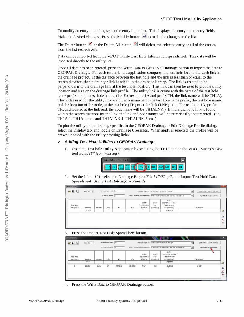
DO N
OT
DIST
RIBU
TE -
Prin
ting
for S
tude
nt U
se is
Per
mitt
ed
Co
mpa
ny: V
irgin
ia D
OT
C
lass
Dat
e: 2
0-M
ay-2
013
VDOT Test Hole Utility Application
VDOT GEOPAK Drainage © 2011 Bentley Systems, Incorporated 7-11
To modify an entry in the list, select the entry in the list. This displays the entry in the entry fields. Make the desired changes. Press the Modify button to make the changes in the list.
The Delete button or the Delete All button will delete the selected entry or all of the entries from the list respectively.
Data can be imported from the VDOT Utility Test Hole Information spreadsheet. This data will be imported directly to the utility list.
Once all data has been entered, press the Write Data to GEOPAK Drainage button to import the data to GEOPAK Drainage. For each test hole, the application compares the test hole location to each link in the drainage project. If the distance between the test hole and the link is less than or equal to the search distance, then a drainage link is added to the drainage library. The link is created to be perpendicular to the drainage link at the test hole location. This link can then be used to plot the utility location and size on the drainage link profile. The utility link is create with the name of the test hole name prefix and the test hole name. (i.e. For test hole 1A and prefix TH, the link name will be TH1A). The nodes used for the utility link are given a name using the test hole name prefix, the test hole name, and the location of the node, at the test hole (TH) or at the link (LNK). (i.e. For test hole 1A, prefix TH, and located at the link end, the node name will be TH1ALNK.) If more than one link is found within the search distance for the link, the link and node names will be numerically incremented. (i.e. TH1A-1, TH1A-2, etc. and TH1ALNK-1, TH1ALNK-2, etc.)
To plot the utility on the drainage profile, in the GEOPAK Drainage > Edit Drainage Profile dialog, select the Display tab, and toggle on Drainage Crossings. When apply is selected, the profile will be drawn/updated with the utility crossing links.
> Adding Test Hole Utilities to GEOPAK Drainage 1. Open the Test hole Utility Application by selecting the THU icon on the VDOT Macro’s Task
tool frame (6th
icon from left).
2. Set the Job to 101, select the Drainage Project File:h17682.gdf, and Import Test Hold Data Spreadsheet: Utility Test Hole Information.xls
3. Press the Import Test Hole Spreadsheet button.
4. Press the Write Data to GEOPAK Drainage button.
DO N
OT
DIST
RIBU
TE -
Prin
ting
for S
tude
nt U
se is
Per
mitt
ed
Co
mpa
ny: V
irgin
ia D
OT
C
lass
Dat
e: 2
0-M
ay-2
013
VDOT Test Hole Utility Application
7-12 © 2011 Bentley Systems, Incorporated VDOT GEOPAK Drainage
5. Click the Save icon and save off the test hole data. Name the file h17682.thd 6. Close the Test Hole Utility dialog. 7. Open the Node Configuration dialog in Drainage and review the data. 8. Open the Link Configuration dialog in Drainage and review the data. 9. Close the dialogs when finished.
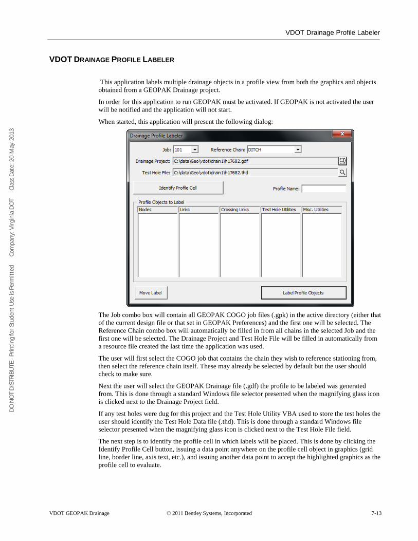
DO N
OT
DIST
RIBU
TE -
Prin
ting
for S
tude
nt U
se is
Per
mitt
ed
Co
mpa
ny: V
irgin
ia D
OT
C
lass
Dat
e: 2
0-M
ay-2
013
VDOT Drainage Profile Labeler
VDOT GEOPAK Drainage © 2011 Bentley Systems, Incorporated 7-13
VDOT DRAINAGE PROFILE LABELER
This application labels multiple drainage objects in a profile view from both the graphics and objects obtained from a GEOPAK Drainage project.
In order for this application to run GEOPAK must be activated. If GEOPAK is not activated the user will be notified and the application will not start.
When started, this application will present the following dialog:
The Job combo box will contain all GEOPAK COGO job files (.gpk) in the active directory (either that of the current design file or that set in GEOPAK Preferences) and the first one will be selected. The Reference Chain combo box will automatically be filled in from all chains in the selected Job and the first one will be selected. The Drainage Project and Test Hole File will be filled in automatically from a resource file created the last time the application was used.
The user will first select the COGO job that contains the chain they wish to reference stationing from, then select the reference chain itself. These may already be selected by default but the user should check to make sure.
Next the user will select the GEOPAK Drainage file (.gdf) the profile to be labeled was generated from. This is done through a standard Windows file selector presented when the magnifying glass icon is clicked next to the Drainage Project field.
If any test holes were dug for this project and the Test Hole Utility VBA used to store the test holes the user should identify the Test Hole Data file (.thd). This is done through a standard Windows file selector presented when the magnifying glass icon is clicked next to the Test Hole File field.
The next step is to identify the profile cell in which labels will be placed. This is done by clicking the Identify Profile Cell button, issuing a data point anywhere on the profile cell object in graphics (grid line, border line, axis text, etc.), and issuing another data point to accept the highlighted graphics as the profile cell to evaluate.
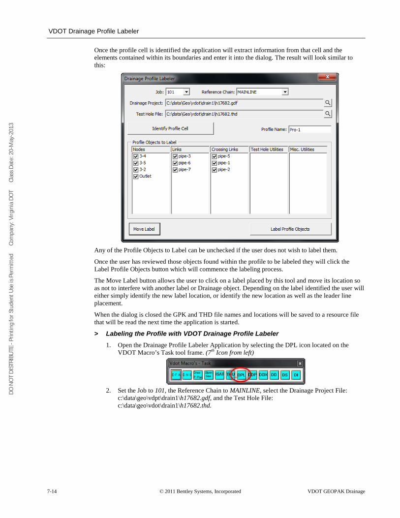
DO N
OT
DIST
RIBU
TE -
Prin
ting
for S
tude
nt U
se is
Per
mitt
ed
Co
mpa
ny: V
irgin
ia D
OT
C
lass
Dat
e: 2
0-M
ay-2
013
VDOT Drainage Profile Labeler
7-14 © 2011 Bentley Systems, Incorporated VDOT GEOPAK Drainage
Once the profile cell is identified the application will extract information from that cell and the elements contained within its boundaries and enter it into the dialog. The result will look similar to this:
Any of the Profile Objects to Label can be unchecked if the user does not wish to label them.
Once the user has reviewed those objects found within the profile to be labeled they will click the Label Profile Objects button which will commence the labeling process.
The Move Label button allows the user to click on a label placed by this tool and move its location so as not to interfere with another label or Drainage object. Depending on the label identified the user will either simply identify the new label location, or identify the new location as well as the leader line placement.
When the dialog is closed the GPK and THD file names and locations will be saved to a resource file that will be read the next time the application is started.
> Labeling the Profile with VDOT Drainage Profile Labeler 1. Open the Drainage Profile Labeler Application by selecting the DPL icon located on the
VDOT Macro’s Task tool frame. (7th
Icon from left)
2. Set the Job to 101, the Reference Chain to MAINLINE, select the Drainage Project File: c:\data\geo\vdpt\drain1\h17682.gdf, and the Test Hole File: c:\data\geo\vdot\drain1\h17682.thd.
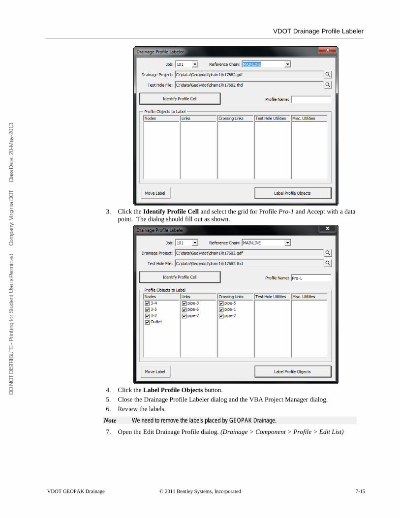
DO N
OT
DIST
RIBU
TE -
Prin
ting
for S
tude
nt U
se is
Per
mitt
ed
Co
mpa
ny: V
irgin
ia D
OT
C
lass
Dat
e: 2
0-M
ay-2
013
VDOT Drainage Profile Labeler
VDOT GEOPAK Drainage © 2011 Bentley Systems, Incorporated 7-15
3. Click the Identify Profile Cell and select the grid for Profile Pro-1 and Accept with a data
point. The dialog should fill out as shown.
4. Click the Label Profile Objects button. 5. Close the Drainage Profile Labeler dialog and the VBA Project Manager dialog. 6. Review the labels.
Note We need to remove the labels placed by GEOPAK Drainage.
7. Open the Edit Drainage Profile dialog. (Drainage > Component > Profile > Edit List)
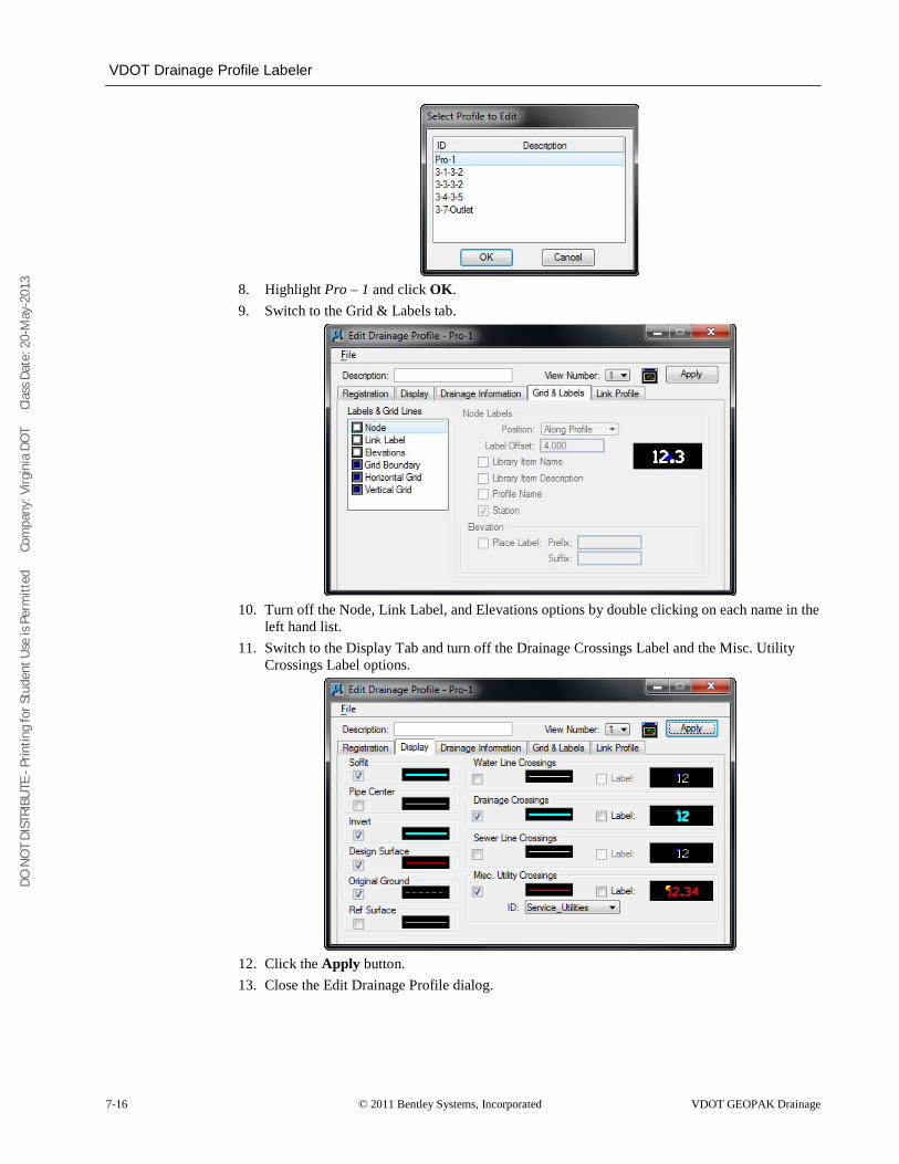
DO N
OT
DIST
RIBU
TE -
Prin
ting
for S
tude
nt U
se is
Per
mitt
ed
Co
mpa
ny: V
irgin
ia D
OT
C
lass
Dat
e: 2
0-M
ay-2
013
VDOT Drainage Profile Labeler
7-16 © 2011 Bentley Systems, Incorporated VDOT GEOPAK Drainage
8. Highlight Pro – 1 and click OK. 9. Switch to the Grid & Labels tab.
10. Turn off the Node, Link Label, and Elevations options by double clicking on each name in the
left hand list. 11. Switch to the Display Tab and turn off the Drainage Crossings Label and the Misc. Utility
Crossings Label options.
12. Click the Apply button. 13. Close the Edit Drainage Profile dialog.
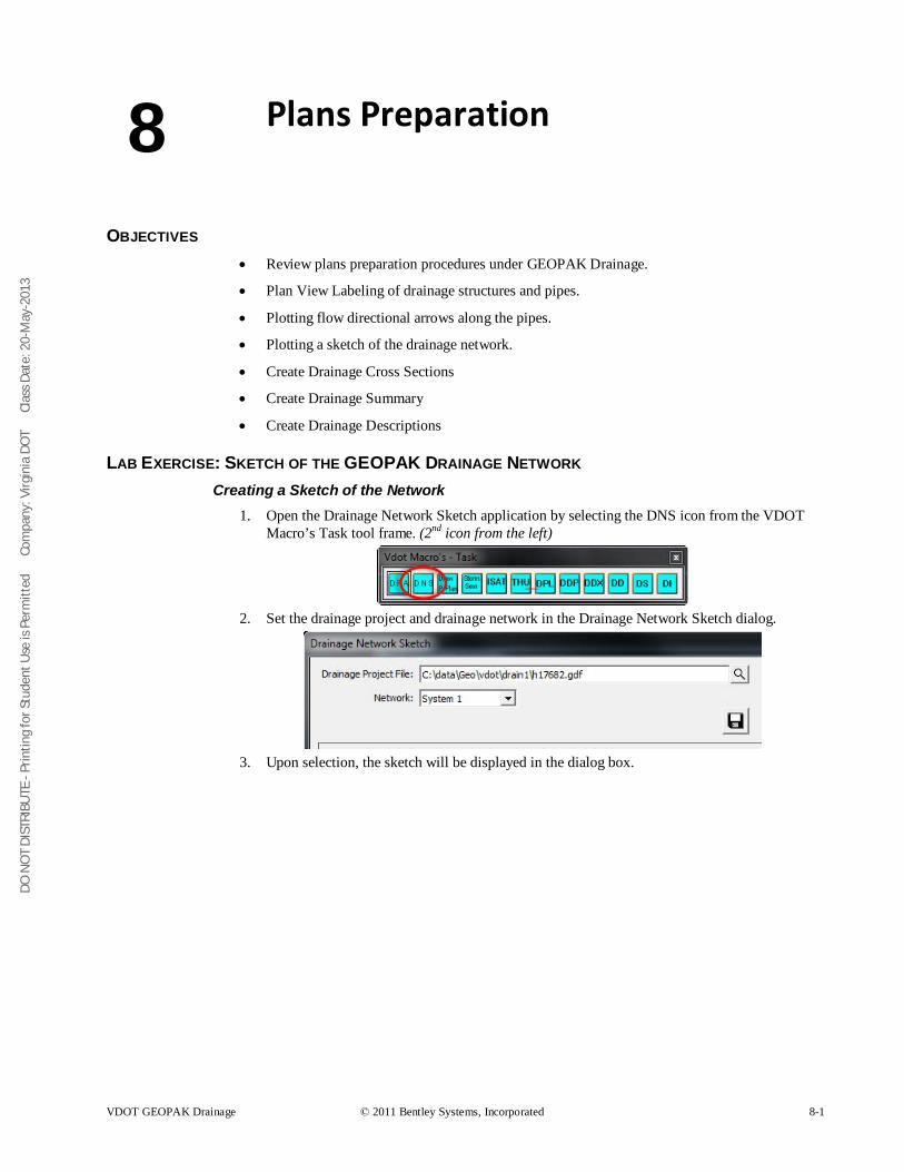
DO N
OT
DIST
RIBU
TE -
Prin
ting
for S
tude
nt U
se is
Per
mitt
ed
Co
mpa
ny: V
irgin
ia D
OT
C
lass
Dat
e: 2
0-M
ay-2
013
VDOT GEOPAK Drainage © 2011 Bentley Systems, Incorporated 8-1
Plans Preparation
OBJECTIVES • Review plans preparation procedures under GEOPAK Drainage.
• Plan View Labeling of drainage structures and pipes.
• Plotting flow directional arrows along the pipes.
• Plotting a sketch of the drainage network.
• Create Drainage Cross Sections
• Create Drainage Summary
• Create Drainage Descriptions
LAB EXERCISE: SKETCH OF THE GEOPAK DRAINAGE NETWORK Creating a Sketch of the Network
1. Open the Drainage Network Sketch application by selecting the DNS icon from the VDOT Macro’s Task tool frame. (2nd icon from the left)
2. Set the drainage project and drainage network in the Drainage Network Sketch dialog.
3. Upon selection, the sketch will be displayed in the dialog box.
8
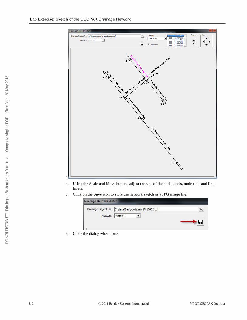
DO N
OT
DIST
RIBU
TE -
Prin
ting
for S
tude
nt U
se is
Per
mitt
ed
Co
mpa
ny: V
irgin
ia D
OT
C
lass
Dat
e: 2
0-M
ay-2
013
Lab Exercise: Sketch of the GEOPAK Drainage Network
8-2 © 2011 Bentley Systems, Incorporated VDOT GEOPAK Drainage
9 4. Using the Scale and Move buttons adjust the size of the node labels, node cells and link
labels. 5. Click on the Save icon to store the network sketch as a JPG image file.
6. Close the dialog when done.
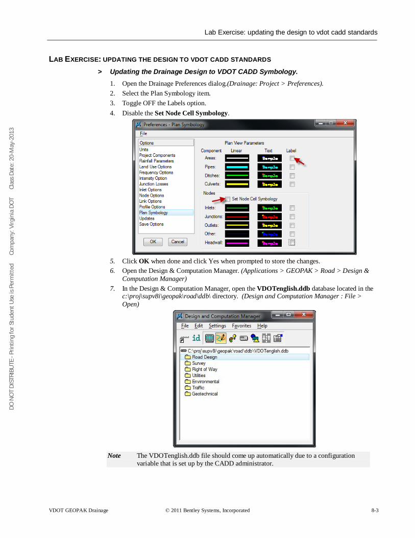
DO N
OT
DIST
RIBU
TE -
Prin
ting
for S
tude
nt U
se is
Per
mitt
ed
Co
mpa
ny: V
irgin
ia D
OT
C
lass
Dat
e: 2
0-M
ay-2
013
Lab Exercise: updating the design to vdot cadd standards
VDOT GEOPAK Drainage © 2011 Bentley Systems, Incorporated 8-3
LAB EXERCISE: UPDATING THE DESIGN TO VDOT CADD STANDARDS > Updating the Drainage Design to VDOT CADD Symbology.
1. Open the Drainage Preferences dialog.(Drainage: Project > Preferences). 2. Select the Plan Symbology item. 3. Toggle OFF the Labels option. 4. Disable the Set Node Cell Symbology.
5. Click OK when done and click Yes when prompted to store the changes. 6. Open the Design & Computation Manager. (Applications > GEOPAK > Road > Design &
Computation Manager) 7. In the Design & Computation Manager, open the VDOTenglish.ddb database located in the
c:\proj\supv8i\geopak\road\ddb\ directory. (Design and Computation Manager : File > Open)
Note
The VDOTenglish.ddb file should come up automatically due to a configuration variable that is set up by the CADD administrator.
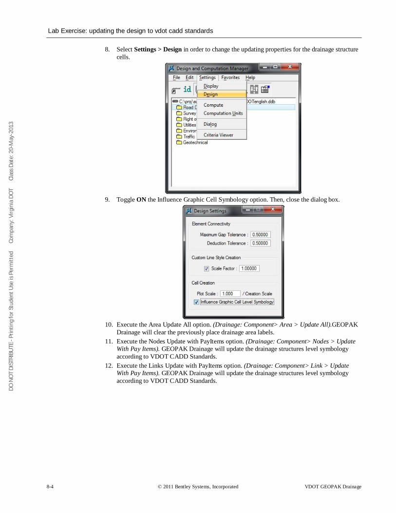
DO N
OT
DIST
RIBU
TE -
Prin
ting
for S
tude
nt U
se is
Per
mitt
ed
Co
mpa
ny: V
irgin
ia D
OT
C
lass
Dat
e: 2
0-M
ay-2
013
Lab Exercise: updating the design to vdot cadd standards
8-4 © 2011 Bentley Systems, Incorporated VDOT GEOPAK Drainage
8. Select Settings > Design in order to change the updating properties for the drainage structure cells.
9. Toggle ON the Influence Graphic Cell Symbology option. Then, close the dialog box.
10. Execute the Area Update All option. (Drainage: Component> Area > Update All).GEOPAK
Drainage will clear the previously place drainage area labels. 11. Execute the Nodes Update with PayItems option. (Drainage: Component> Nodes > Update
With Pay Items). GEOPAK Drainage will update the drainage structures level symbology according to VDOT CADD Standards.
12. Execute the Links Update with PayItems option. (Drainage: Component> Link > Update With Pay Items). GEOPAK Drainage will update the drainage structures level symbology according to VDOT CADD Standards.
DO N
OT
DIST
RIBU
TE -
Prin
ting
for S
tude
nt U
se is
Per
mitt
ed
Co
mpa
ny: V
irgin
ia D
OT
C
lass
Dat
e: 2
0-M
ay-2
013
Plan View Labeling
VDOT GEOPAK Drainage © 2011 Bentley Systems, Incorporated 8-5
PLAN VIEW LABELING The Labeling automates the composition and placement of plan labels onto drawings. This interactive tool permits the creation of very simple to complex labels using many of the following features:
• Numerous Computed Text Inserts permit standardized computed values to be easily incorporated into labels. These standardized computed values are based on the type of element to be labeled and change as you select different elements. Types of elements available for computed inserts include points, lines, arcs, complex graphic elements, COGO features, and drainage features.
• User Text Inserts facilitate the simple inclusion of user defined text strings into the label. These User Inserts can be customized to include frequently used labeling terms and be saved for continual use.
• Standard shapes can be placed around labels and to accommodate different plan label formats. • Standard leader lines and leader line terminators can also be utilized to create the desired label
formats. • Frequently utilized labels can be stored as Label Styles for subsequent recall. The complete label,
including computed text inserts, user inserts, shapes, and leaders, are all stored within the Style. • Tools to edit, move, and extract labels are also provided to make manipulation and plan changes
easier. • Enhanced ASCII is supported by use of the (\) symbol. • Styles are supported, whereby often used labels and associated settings can be saved off and
recalled in subsequent sessions. • Updating options provide for efficient changing as the project dictates changes in the design.
While the labeler can be used for generic purposes, several of the fields are set up for specific applications. The specialty modes include:
• Plan View • Profile • Cross Section • Drainage • Site • Water and Sewer
Under each mode, the types of elements available to label and the associated text inserts change.
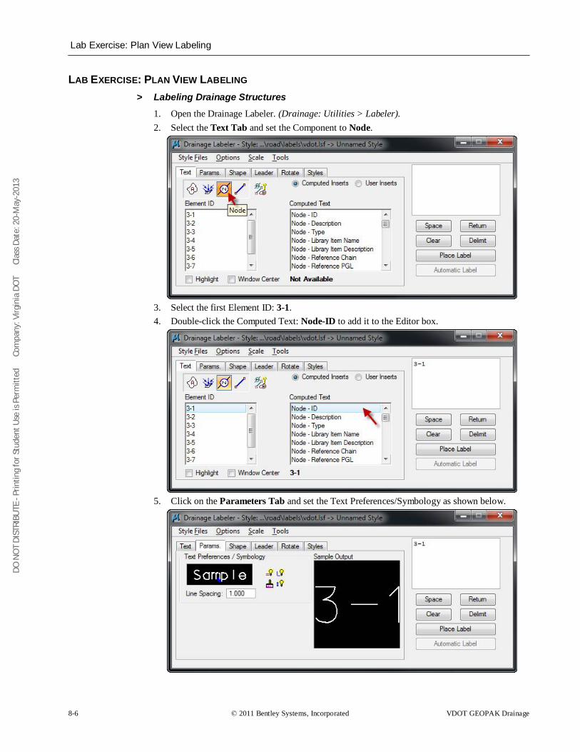
DO N
OT
DIST
RIBU
TE -
Prin
ting
for S
tude
nt U
se is
Per
mitt
ed
Co
mpa
ny: V
irgin
ia D
OT
C
lass
Dat
e: 2
0-M
ay-2
013
Lab Exercise: Plan View Labeling
8-6 © 2011 Bentley Systems, Incorporated VDOT GEOPAK Drainage
LAB EXERCISE: PLAN VIEW LABELING > Labeling Drainage Structures
1. Open the Drainage Labeler. (Drainage: Utilities > Labeler). 2. Select the Text Tab and set the Component to Node.
3. Select the first Element ID: 3-1. 4. Double-click the Computed Text: Node-ID to add it to the Editor box.
5. Click on the Parameters Tab and set the Text Preferences/Symbology as shown below.
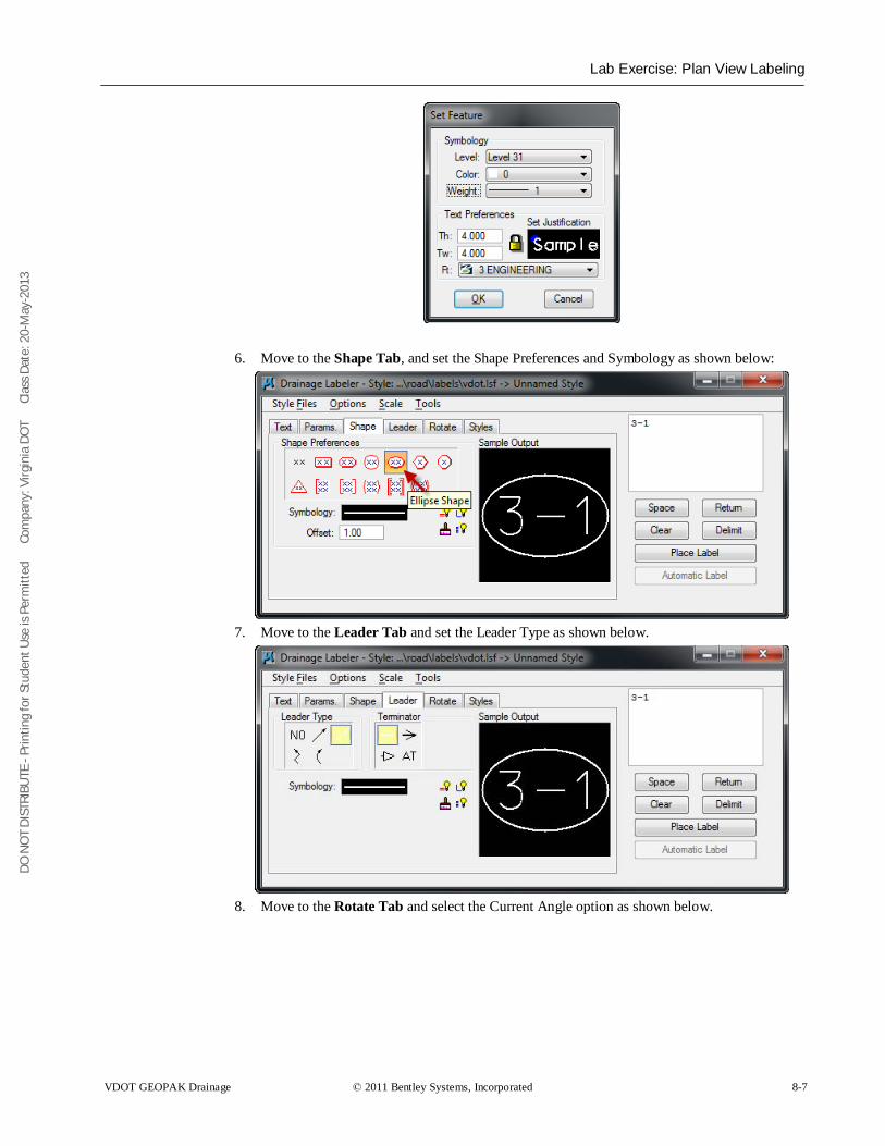
DO N
OT
DIST
RIBU
TE -
Prin
ting
for S
tude
nt U
se is
Per
mitt
ed
Co
mpa
ny: V
irgin
ia D
OT
C
lass
Dat
e: 2
0-M
ay-2
013
Lab Exercise: Plan View Labeling
VDOT GEOPAK Drainage © 2011 Bentley Systems, Incorporated 8-7
6. Move to the Shape Tab, and set the Shape Preferences and Symbology as shown below:
7. Move to the Leader Tab and set the Leader Type as shown below.
8. Move to the Rotate Tab and select the Current Angle option as shown below.

DO N
OT
DIST
RIBU
TE -
Prin
ting
for S
tude
nt U
se is
Per
mitt
ed
Co
mpa
ny: V
irgin
ia D
OT
C
lass
Dat
e: 2
0-M
ay-2
013
Lab Exercise: Plan View Labeling
8-8 © 2011 Bentley Systems, Incorporated VDOT GEOPAK Drainage
9. Place the label in the design file by clicking Place Label.
10. Create a new Style by moving to the Styles Tab and clicking on New Style. Provide a style
name for the label, and press OK.
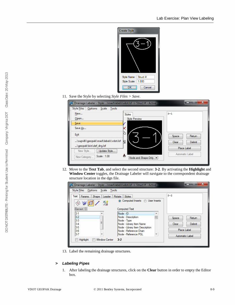
DO N
OT
DIST
RIBU
TE -
Prin
ting
for S
tude
nt U
se is
Per
mitt
ed
Co
mpa
ny: V
irgin
ia D
OT
C
lass
Dat
e: 2
0-M
ay-2
013
Lab Exercise: Plan View Labeling
VDOT GEOPAK Drainage © 2011 Bentley Systems, Incorporated 8-9
11. Save the Style by selecting Style Files > Save.
12. Move to the Text Tab, and select the second structure: 3-2. By activating the Highlight and
Window Center toggles, the Drainage Labeler will navigate to the correspondent drainage structure location in the dgn file.
13. Label the remaining drainage structures.
> Labeling Pipes 1. After labeling the drainage structures, click on the Clear button in order to empty the Editor
box.
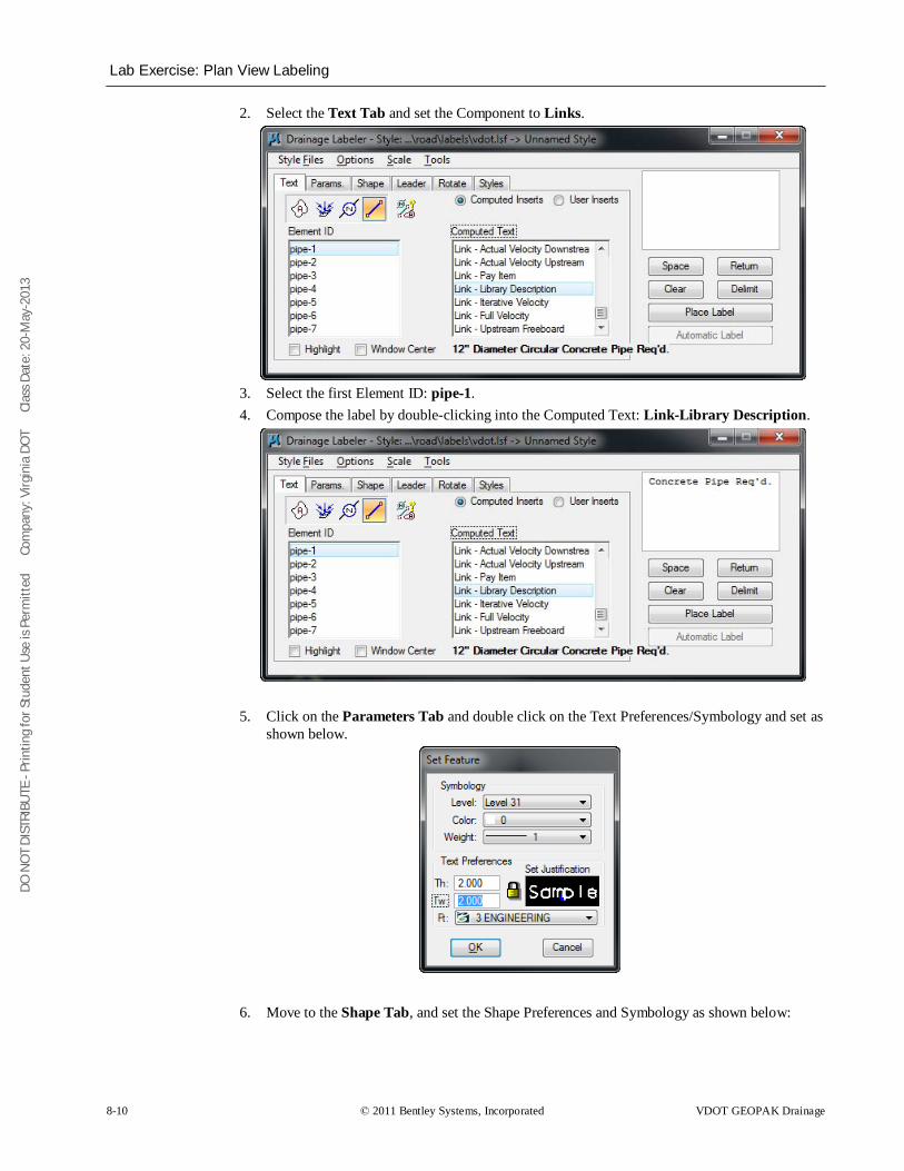
DO N
OT
DIST
RIBU
TE -
Prin
ting
for S
tude
nt U
se is
Per
mitt
ed
Co
mpa
ny: V
irgin
ia D
OT
C
lass
Dat
e: 2
0-M
ay-2
013
Lab Exercise: Plan View Labeling
8-10 © 2011 Bentley Systems, Incorporated VDOT GEOPAK Drainage
2. Select the Text Tab and set the Component to Links.
3. Select the first Element ID: pipe-1. 4. Compose the label by double-clicking into the Computed Text: Link-Library Description.
5. Click on the Parameters Tab and double click on the Text Preferences/Symbology and set as shown below.
6. Move to the Shape Tab, and set the Shape Preferences and Symbology as shown below:
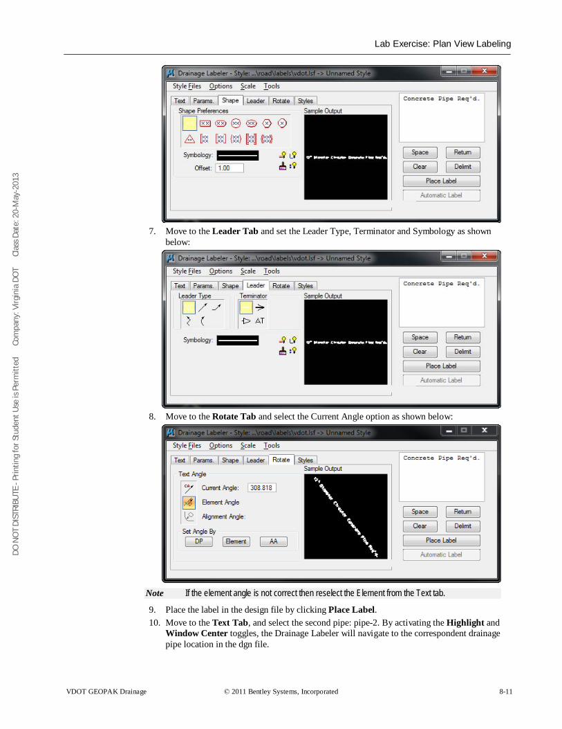
DO N
OT
DIST
RIBU
TE -
Prin
ting
for S
tude
nt U
se is
Per
mitt
ed
Co
mpa
ny: V
irgin
ia D
OT
C
lass
Dat
e: 2
0-M
ay-2
013
Lab Exercise: Plan View Labeling
VDOT GEOPAK Drainage © 2011 Bentley Systems, Incorporated 8-11
7. Move to the Leader Tab and set the Leader Type, Terminator and Symbology as shown
below:
8. Move to the Rotate Tab and select the Current Angle option as shown below:
Note If the element angle is not correct then reselect the Element from the Text tab.
9. Place the label in the design file by clicking Place Label. 10. Move to the Text Tab, and select the second pipe: pipe-2. By activating the Highlight and
Window Center toggles, the Drainage Labeler will navigate to the correspondent drainage pipe location in the dgn file.
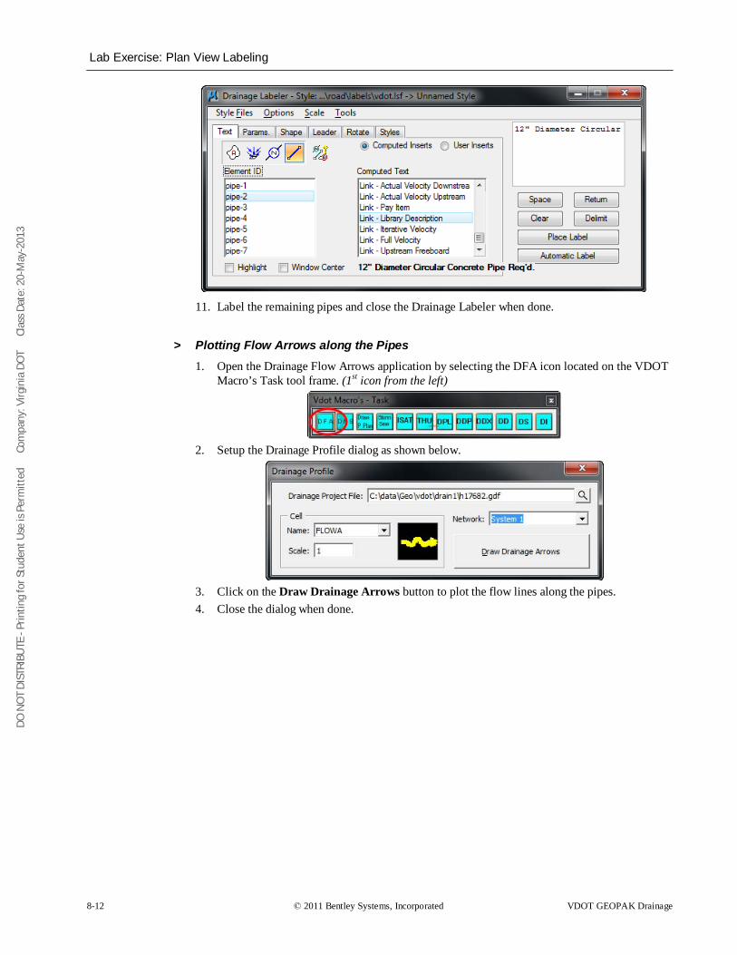
DO N
OT
DIST
RIBU
TE -
Prin
ting
for S
tude
nt U
se is
Per
mitt
ed
Co
mpa
ny: V
irgin
ia D
OT
C
lass
Dat
e: 2
0-M
ay-2
013
Lab Exercise: Plan View Labeling
8-12 © 2011 Bentley Systems, Incorporated VDOT GEOPAK Drainage
11. Label the remaining pipes and close the Drainage Labeler when done.
> Plotting Flow Arrows along the Pipes 1. Open the Drainage Flow Arrows application by selecting the DFA icon located on the VDOT
Macro’s Task tool frame. (1st icon from the left)
2. Setup the Drainage Profile dialog as shown below.
3. Click on the Draw Drainage Arrows button to plot the flow lines along the pipes. 4. Close the dialog when done.
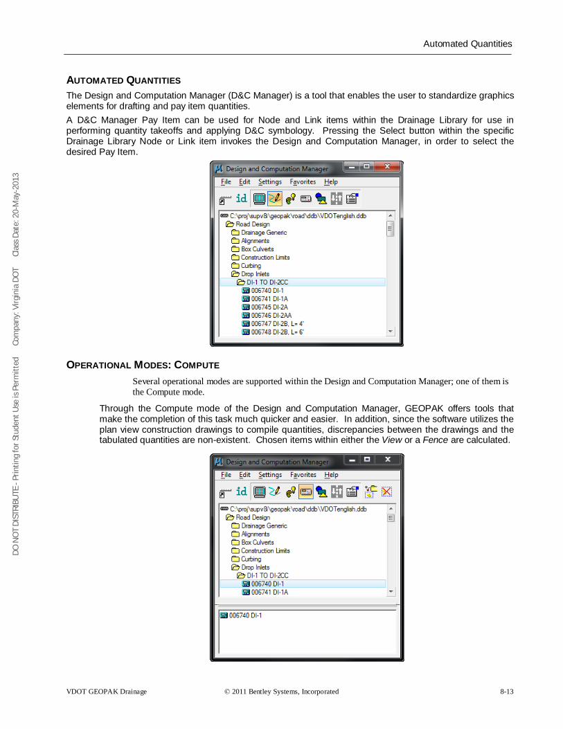
DO N
OT
DIST
RIBU
TE -
Prin
ting
for S
tude
nt U
se is
Per
mitt
ed
Co
mpa
ny: V
irgin
ia D
OT
C
lass
Dat
e: 2
0-M
ay-2
013
Automated Quantities
VDOT GEOPAK Drainage © 2011 Bentley Systems, Incorporated 8-13
AUTOMATED QUANTITIES The Design and Computation Manager (D&C Manager) is a tool that enables the user to standardize graphics elements for drafting and pay item quantities. A D&C Manager Pay Item can be used for Node and Link items within the Drainage Library for use in performing quantity takeoffs and applying D&C symbology. Pressing the Select button within the specific Drainage Library Node or Link item invokes the Design and Computation Manager, in order to select the desired Pay Item.
OPERATIONAL MODES: COMPUTE Several operational modes are supported within the Design and Computation Manager; one of them is the Compute mode.
Through the Compute mode of the Design and Computation Manager, GEOPAK offers tools that make the completion of this task much quicker and easier. In addition, since the software utilizes the plan view construction drawings to compile quantities, discrepancies between the drawings and the tabulated quantities are non-existent. Chosen items within either the View or a Fence are calculated.
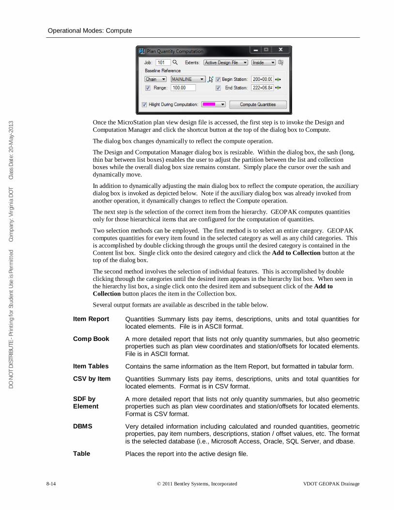
DO N
OT
DIST
RIBU
TE -
Prin
ting
for S
tude
nt U
se is
Per
mitt
ed
Co
mpa
ny: V
irgin
ia D
OT
C
lass
Dat
e: 2
0-M
ay-2
013
Operational Modes: Compute
8-14 © 2011 Bentley Systems, Incorporated VDOT GEOPAK Drainage
Once the MicroStation plan view design file is accessed, the first step is to invoke the Design and Computation Manager and click the shortcut button at the top of the dialog box to Compute.
The dialog box changes dynamically to reflect the compute operation.
The Design and Computation Manager dialog box is resizable. Within the dialog box, the sash (long, thin bar between list boxes) enables the user to adjust the partition between the list and collection boxes while the overall dialog box size remains constant. Simply place the cursor over the sash and dynamically move.
In addition to dynamically adjusting the main dialog box to reflect the compute operation, the auxiliary dialog box is invoked as depicted below. Note if the auxiliary dialog box was already invoked from another operation, it dynamically changes to reflect the Compute operation.
The next step is the selection of the correct item from the hierarchy. GEOPAK computes quantities only for those hierarchical items that are configured for the computation of quantities.
Two selection methods can be employed. The first method is to select an entire category. GEOPAK computes quantities for every item found in the selected category as well as any child categories. This is accomplished by double clicking through the groups until the desired category is contained in the Content list box. Single click onto the desired category and click the Add to Collection button at the top of the dialog box.
The second method involves the selection of individual features. This is accomplished by double clicking through the categories until the desired item appears in the hierarchy list box. When seen in the hierarchy list box, a single click onto the desired item and subsequent click of the Add to Collection button places the item in the Collection box.
Several output formats are available as described in the table below.
Item Report Quantities Summary lists pay items, descriptions, units and total quantities for located elements. File is in ASCII format.
Comp Book A more detailed report that lists not only quantity summaries, but also geometric properties such as plan view coordinates and station/offsets for located elements. File is in ASCII format.
Item Tables Contains the same information as the Item Report, but formatted in tabular form.
CSV by Item Quantities Summary lists pay items, descriptions, units and total quantities for located elements. Format is in CSV format.
SDF by Element
A more detailed report that lists not only quantity summaries, but also geometric properties such as plan view coordinates and station/offsets for located elements. Format is CSV format.
DBMS Very detailed information including calculated and rounded quantities, geometric properties, pay item numbers, descriptions, station / offset values, etc. The format is the selected database (i.e., Microsoft Access, Oracle, SQL Server, and dbase.
Table Places the report into the active design file.
DO N
OT
DIST
RIBU
TE -
Prin
ting
for S
tude
nt U
se is
Per
mitt
ed
Co
mpa
ny: V
irgin
ia D
OT
C
lass
Dat
e: 2
0-M
ay-2
013
Operational Modes: Compute
VDOT GEOPAK Drainage © 2011 Bentley Systems, Incorporated 8-15
An option button located on the left side of the Compute auxiliary dialog box dictates the Output. Options that apply to various Output types are detailed in the table below
View / Fence If the View toggle is selected, only selected items that can be seen in MicroStation view one will be computed. If the view includes area outside of the Range, the Range will override. If the Fence toggle is selected, a fence must be placed, and all specified graphical features, which are inside both the fence, and the Range will be tabulated. The Fence mode is sensitive to the MicroStation Inside, Overlap and Clip modes.
File / Preview If set to File, GEOPAK creates the file whose file format is based on the Output type and whose name is defined in the key-in field to the right of the File option. The name can be manually entered or selected via the Files (folder) icon. The file can be created or appended to an existing file. If desired, a full path may be specified, otherwise, the report will be found in the current directory. If the option is set to Preview, the file is not created and the output is displayed in a GEOPAK window.
Description Any description keyed within this field will be printed at the top of the report. There is a maximum of 48 characters supported for this field.
Display These short cut icons are functionally identical to the Display mode in the main dialog box and are discussed in the next section.
Highlight in Computation
When activated, all MicroStation elements utilized in computations are highlighted.
Compute Commences the computation process.
Job Number GEOPAK Coordinate geometry database (GPK) file wherein the specified chain is stored.
Chain Requires a minimum of one chain, which must be stored in the specified job number.
Select When selected, the Chain Selector dialog box appears, wherein the user can select the desired chain.
Range Left and right offset limits (in master units) from the chain where the quantities will be computed. Any specified item located outside of the limits is not included in the report
Phase Quantities can be separated into various phases, as a means to group various pay items. Default phases include: Design, Preliminary, and Final. Note the user can add new phases, but must be aware of naming limitations of downstream applications (i.e., Transport links in Quantities Manager.)
Run The user may also runs as a method of grouping various quantities and / or pay items.
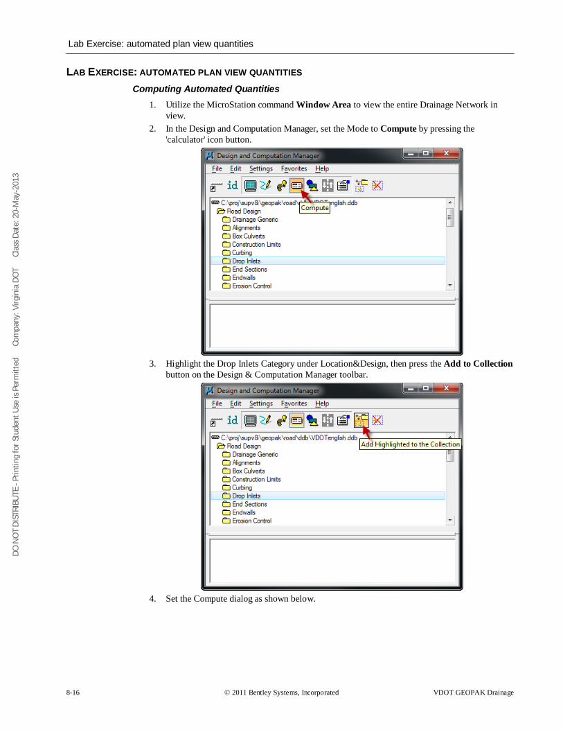
DO N
OT
DIST
RIBU
TE -
Prin
ting
for S
tude
nt U
se is
Per
mitt
ed
Co
mpa
ny: V
irgin
ia D
OT
C
lass
Dat
e: 2
0-M
ay-2
013
Lab Exercise: automated plan view quantities
8-16 © 2011 Bentley Systems, Incorporated VDOT GEOPAK Drainage
LAB EXERCISE: AUTOMATED PLAN VIEW QUANTITIES Computing Automated Quantities
1. Utilize the MicroStation command Window Area to view the entire Drainage Network in view.
2. In the Design and Computation Manager, set the Mode to Compute by pressing the 'calculator' icon button.
3. Highlight the Drop Inlets Category under Location&Design, then press the Add to Collection
button on the Design & Computation Manager toolbar.
4. Set the Compute dialog as shown below.
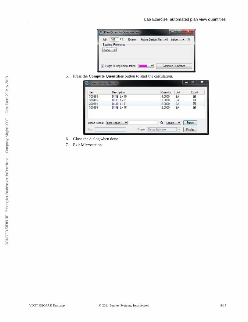
DO N
OT
DIST
RIBU
TE -
Prin
ting
for S
tude
nt U
se is
Per
mitt
ed
Co
mpa
ny: V
irgin
ia D
OT
C
lass
Dat
e: 2
0-M
ay-2
013
Lab Exercise: automated plan view quantities
VDOT GEOPAK Drainage © 2011 Bentley Systems, Incorporated 8-17
5. Press the Compute Quantities button to start the calculation.
6. Close the dialog when done. 7. Exit Microstation.
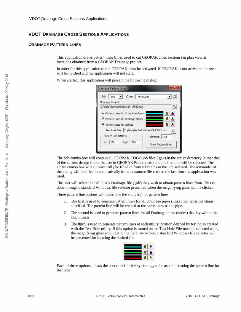
DO N
OT
DIST
RIBU
TE -
Prin
ting
for S
tude
nt U
se is
Per
mitt
ed
Co
mpa
ny: V
irgin
ia D
OT
C
lass
Dat
e: 2
0-M
ay-2
013
VDOT Drainage Cross Sections Applications
8-18 © 2011 Bentley Systems, Incorporated VDOT GEOPAK Drainage
VDOT DRAINAGE CROSS SECTIONS APPLICATIONS
DRAINAGE PATTERN LINES
This application draws pattern lines (lines used to cut GEOPAK cross sections) in plan view at locations obtained from a GEOPAK Drainage project.
In order for this application to run GEOPAK must be activated. If GEOPAK is not activated the user will be notified and the application will not start.
When started, this application will present the following dialog:
The Job combo box will contain all GEOPAK COGO job files (.gpk) in the active directory (either that of the current design file or that set in GEOPAK Preferences) and the first one will be selected. The Chain combo box will automatically be filled in from all chains in the Job selected. The remainder of the dialog will be filled in automatically from a resource file created the last time the application was used.
The user will select the GEOPAK Drainage file (.gdf) they wish to obtain pattern lines from. This is done through a standard Windows file selector presented when the magnifying glass icon is clicked.
Three pattern line options will determine the source(s) for pattern lines:
1. The first is used to generate pattern lines for all Drainage pipes (links) that cross the chain specified. The pattern line will be created at the same skew as the pipe.
2. The second is used to generate pattern lines for all Drainage inlets (nodes) that lay within the chain limits.
3. The third is used to generate pattern lines at each utility location defined by test holes created with the Test Hole utility. If this option is turned on the Test Hole File must be selected using the magnifying glass icon next to the field. As before, a standard Windows file selector will be presented for locating the desired file.
Each of these options allows the user to define the symbology to be used in creating the pattern line for that type:
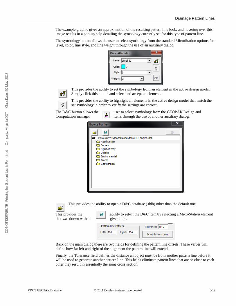
DO N
OT
DIST
RIBU
TE -
Prin
ting
for S
tude
nt U
se is
Per
mitt
ed
Co
mpa
ny: V
irgin
ia D
OT
C
lass
Dat
e: 2
0-M
ay-2
013
Drainage Pattern Lines
VDOT GEOPAK Drainage © 2011 Bentley Systems, Incorporated 8-19
The example graphic gives an approximation of the resulting pattern line look, and hovering over this image results in a pop-up help detailing the symbology currently set for this type of pattern line.
The symbology button allows the user to select symbology from the standard MicroStation options for level, color, line style, and line weight through the use of an auxiliary dialog:
This provides the ability to set the symbology from an element in the active design model. Simply click this button and select and accept an element.
This provides the ability to highlight all elements in the active design model that match the set symbology in order to verify the settings are correct.
The D&C button allows the user to select symbology from the GEOPAK Design and Computation manager items through the use of another auxiliary dialog:
This provides the ability to open a D&C database (.ddb) other than the default one.
This provides the ability to select the D&C item by selecting a MicroStation element that was drawn with a given item.
Back on the main dialog there are two fields for defining the pattern line offsets. These values will define how far left and right of the alignment the pattern line will extend.
Finally, the Tolerance field defines the distance an object must be from another pattern line before it will be used to generate another pattern line. This helps eliminate pattern lines that are so close to each other they result in essentially the same cross section.
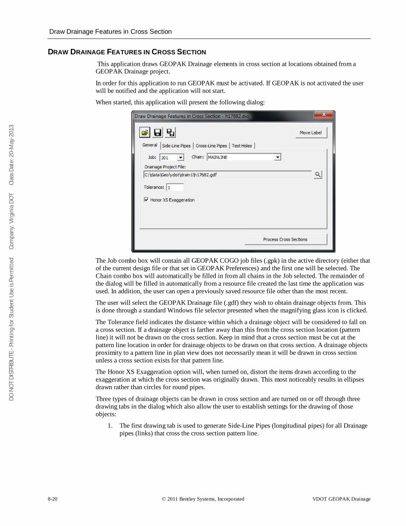
DO N
OT
DIST
RIBU
TE -
Prin
ting
for S
tude
nt U
se is
Per
mitt
ed
Co
mpa
ny: V
irgin
ia D
OT
C
lass
Dat
e: 2
0-M
ay-2
013
Draw Drainage Features in Cross Section
8-20 © 2011 Bentley Systems, Incorporated VDOT GEOPAK Drainage
DRAW DRAINAGE FEATURES IN CROSS SECTION This application draws GEOPAK Drainage elements in cross section at locations obtained from a GEOPAK Drainage project.
In order for this application to run GEOPAK must be activated. If GEOPAK is not activated the user will be notified and the application will not start.
When started, this application will present the following dialog:
The Job combo box will contain all GEOPAK COGO job files (.gpk) in the active directory (either that of the current design file or that set in GEOPAK Preferences) and the first one will be selected. The Chain combo box will automatically be filled in from all chains in the Job selected. The remainder of the dialog will be filled in automatically from a resource file created the last time the application was used. In addition, the user can open a previously saved resource file other than the most recent.
The user will select the GEOPAK Drainage file (.gdf) they wish to obtain drainage objects from. This is done through a standard Windows file selector presented when the magnifying glass icon is clicked.
The Tolerance field indicates the distance within which a drainage object will be considered to fall on a cross section. If a drainage object is farther away than this from the cross section location (pattern line) it will not be drawn on the cross section. Keep in mind that a cross section must be cut at the pattern line location in order for drainage objects to be drawn on that cross section. A drainage objects proximity to a pattern line in plan view does not necessarily mean it will be drawn in cross section unless a cross section exists for that pattern line.
The Honor XS Exaggeration option will, when turned on, distort the items drawn according to the exaggeration at which the cross section was originally drawn. This most noticeably results in ellipses drawn rather than circles for round pipes.
Three types of drainage objects can be drawn in cross section and are turned on or off through three drawing tabs in the dialog which also allow the user to establish settings for the drawing of those objects:
1. The first drawing tab is used to generate Side-Line Pipes (longitudinal pipes) for all Drainage pipes (links) that cross the cross section pattern line.
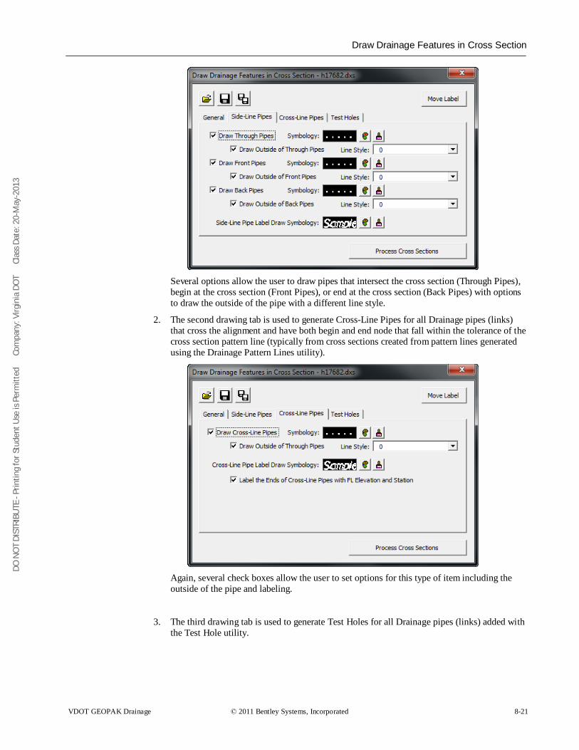
DO N
OT
DIST
RIBU
TE -
Prin
ting
for S
tude
nt U
se is
Per
mitt
ed
Co
mpa
ny: V
irgin
ia D
OT
C
lass
Dat
e: 2
0-M
ay-2
013
Draw Drainage Features in Cross Section
VDOT GEOPAK Drainage © 2011 Bentley Systems, Incorporated 8-21
Several options allow the user to draw pipes that intersect the cross section (Through Pipes), begin at the cross section (Front Pipes), or end at the cross section (Back Pipes) with options to draw the outside of the pipe with a different line style.
2. The second drawing tab is used to generate Cross-Line Pipes for all Drainage pipes (links) that cross the alignment and have both begin and end node that fall within the tolerance of the cross section pattern line (typically from cross sections created from pattern lines generated using the Drainage Pattern Lines utility).
Again, several check boxes allow the user to set options for this type of item including the outside of the pipe and labeling.
3. The third drawing tab is used to generate Test Holes for all Drainage pipes (links) added with the Test Hole utility.
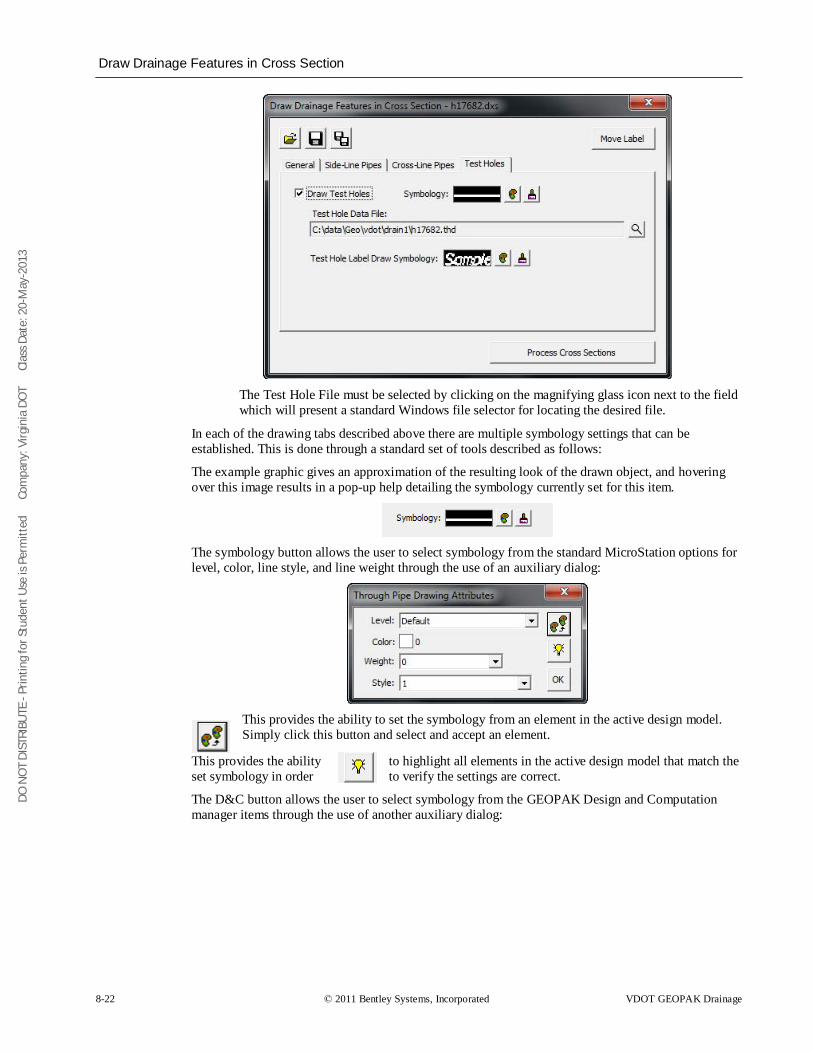
DO N
OT
DIST
RIBU
TE -
Prin
ting
for S
tude
nt U
se is
Per
mitt
ed
Co
mpa
ny: V
irgin
ia D
OT
C
lass
Dat
e: 2
0-M
ay-2
013
Draw Drainage Features in Cross Section
8-22 © 2011 Bentley Systems, Incorporated VDOT GEOPAK Drainage
The Test Hole File must be selected by clicking on the magnifying glass icon next to the field which will present a standard Windows file selector for locating the desired file.
In each of the drawing tabs described above there are multiple symbology settings that can be established. This is done through a standard set of tools described as follows:
The example graphic gives an approximation of the resulting look of the drawn object, and hovering over this image results in a pop-up help detailing the symbology currently set for this item.
The symbology button allows the user to select symbology from the standard MicroStation options for level, color, line style, and line weight through the use of an auxiliary dialog:
This provides the ability to set the symbology from an element in the active design model. Simply click this button and select and accept an element.
This provides the ability to highlight all elements in the active design model that match the set symbology in order to verify the settings are correct.
The D&C button allows the user to select symbology from the GEOPAK Design and Computation manager items through the use of another auxiliary dialog:
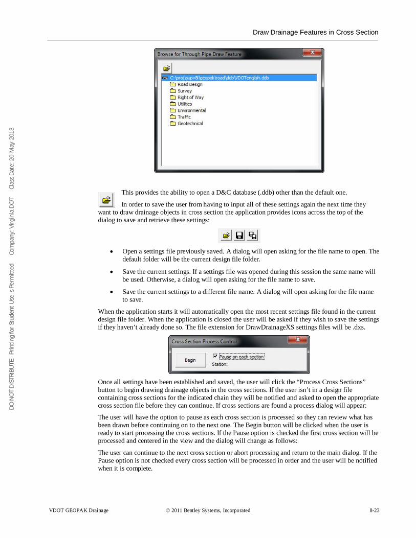
DO N
OT
DIST
RIBU
TE -
Prin
ting
for S
tude
nt U
se is
Per
mitt
ed
Co
mpa
ny: V
irgin
ia D
OT
C
lass
Dat
e: 2
0-M
ay-2
013
Draw Drainage Features in Cross Section
VDOT GEOPAK Drainage © 2011 Bentley Systems, Incorporated 8-23
This provides the ability to open a D&C database (.ddb) other than the default one.
In order to save the user from having to input all of these settings again the next time they want to draw drainage objects in cross section the application provides icons across the top of the dialog to save and retrieve these settings:
• Open a settings file previously saved. A dialog will open asking for the file name to open. The
default folder will be the current design file folder.
• Save the current settings. If a settings file was opened during this session the same name will be used. Otherwise, a dialog will open asking for the file name to save.
• Save the current settings to a different file name. A dialog will open asking for the file name to save.
When the application starts it will automatically open the most recent settings file found in the current design file folder. When the application is closed the user will be asked if they wish to save the settings if they haven’t already done so. The file extension for DrawDrainageXS settings files will be .dxs.
Once all settings have been established and saved, the user will click the “Process Cross Sections” button to begin drawing drainage objects in the cross sections. If the user isn’t in a design file containing cross sections for the indicated chain they will be notified and asked to open the appropriate cross section file before they can continue. If cross sections are found a process dialog will appear:
The user will have the option to pause as each cross section is processed so they can review what has been drawn before continuing on to the next one. The Begin button will be clicked when the user is ready to start processing the cross sections. If the Pause option is checked the first cross section will be processed and centered in the view and the dialog will change as follows:
The user can continue to the next cross section or abort processing and return to the main dialog. If the Pause option is not checked every cross section will be processed in order and the user will be notified when it is complete.
DO N
OT
DIST
RIBU
TE -
Prin
ting
for S
tude
nt U
se is
Per
mitt
ed
Co
mpa
ny: V
irgin
ia D
OT
C
lass
Dat
e: 2
0-M
ay-2
013
Draw Drainage Features in Cross Section
8-24 © 2011 Bentley Systems, Incorporated VDOT GEOPAK Drainage
One final tool at the top-right corner of the main dialog allows the user to Move a Label once it has been placed. This tool will prompt the user to select a label placed by this tool and enable them to change its location as well as the configuration of its leader lines.
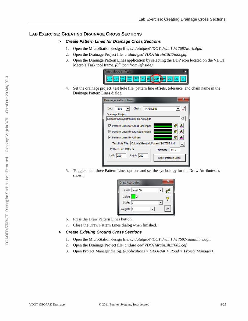
DO N
OT
DIST
RIBU
TE -
Prin
ting
for S
tude
nt U
se is
Per
mitt
ed
Co
mpa
ny: V
irgin
ia D
OT
C
lass
Dat
e: 2
0-M
ay-2
013
Lab Exercise: Creating Drainage Cross Sections
VDOT GEOPAK Drainage © 2011 Bentley Systems, Incorporated 8-25
LAB EXERCISE: CREATING DRAINAGE CROSS SECTIONS > Create Pattern Lines for Drainage Cross Sections
1. Open the MicroStation design file, c:\data\geo\VDOT\drain1\h17682work.dgn. 2. Open the Drainage Project file, c:\data\geo\VDOT\drain1\h17682.gdf. 3. Open the Drainage Pattern Lines application by selecting the DDP icon located on the VDOT
Macro’s Task tool frame. (8th icon from left side)
4. Set the drainage project, test hole file, pattern line offsets, tolerance, and chain name in the
Drainage Pattern Lines dialog.
5. Toggle on all three Pattern Lines options and set the symbology for the Draw Attributes as
shown.
6. Press the Draw Pattern Lines button. 7. Close the Draw Pattern Lines dialog when finished.
> Create Existing Ground Cross Sections
1. Open the MicroStation design file, c:\data\geo\VDOT\drain1\h17682xsmainline.dgn. 2. Open the Drainage Project file, c:\data\geo\VDOT\drain1\h17682.gdf. 3. Open Project Manager dialog. (Applications > GEOPAK > Road > Project Manager).
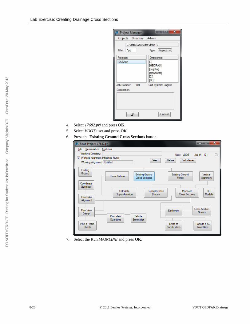
DO N
OT
DIST
RIBU
TE -
Prin
ting
for S
tude
nt U
se is
Per
mitt
ed
Co
mpa
ny: V
irgin
ia D
OT
C
lass
Dat
e: 2
0-M
ay-2
013
Lab Exercise: Creating Drainage Cross Sections
8-26 © 2011 Bentley Systems, Incorporated VDOT GEOPAK Drainage
4. Select 17682.prj and press OK. 5. Select VDOT user and press OK. 6. Press the Existing Ground Cross Sections button.
7. Select the Run MAINLINE and press OK.
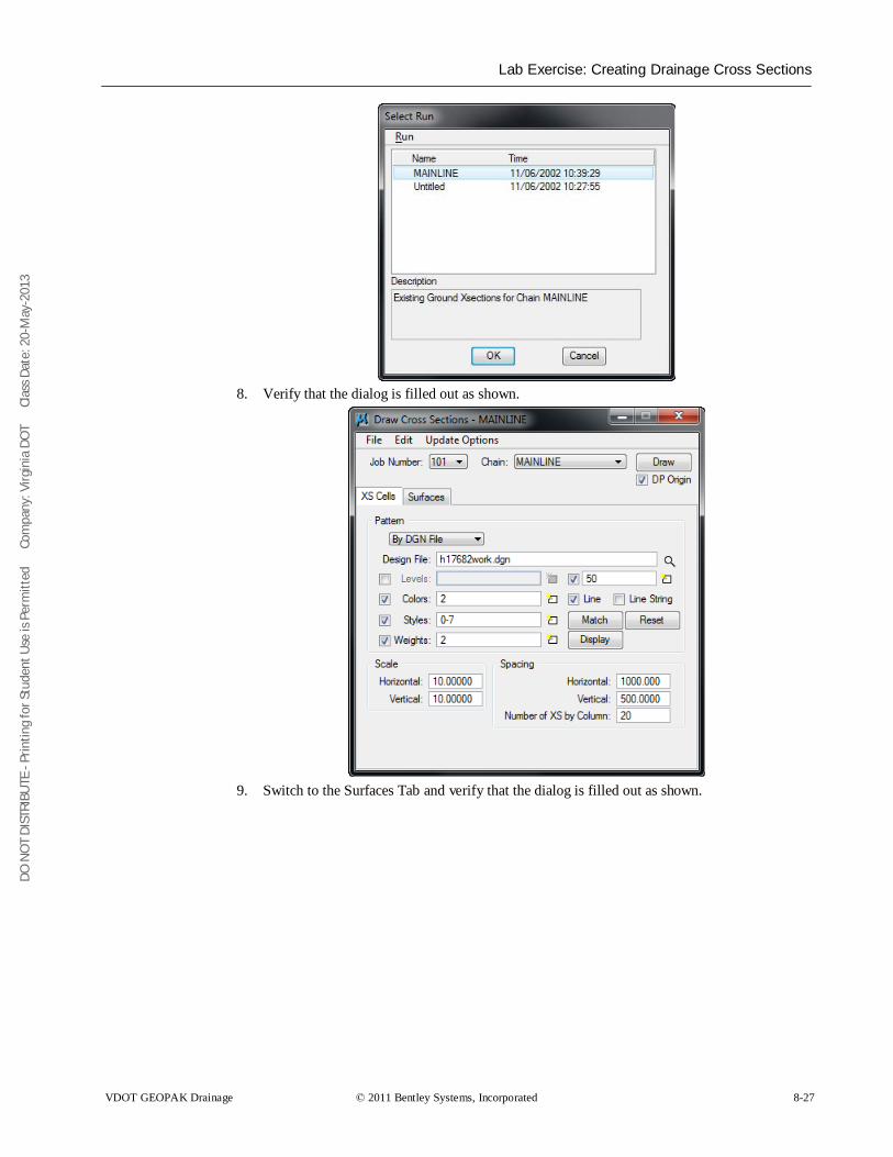
DO N
OT
DIST
RIBU
TE -
Prin
ting
for S
tude
nt U
se is
Per
mitt
ed
Co
mpa
ny: V
irgin
ia D
OT
C
lass
Dat
e: 2
0-M
ay-2
013
Lab Exercise: Creating Drainage Cross Sections
VDOT GEOPAK Drainage © 2011 Bentley Systems, Incorporated 8-27
8. Verify that the dialog is filled out as shown.
9. Switch to the Surfaces Tab and verify that the dialog is filled out as shown.
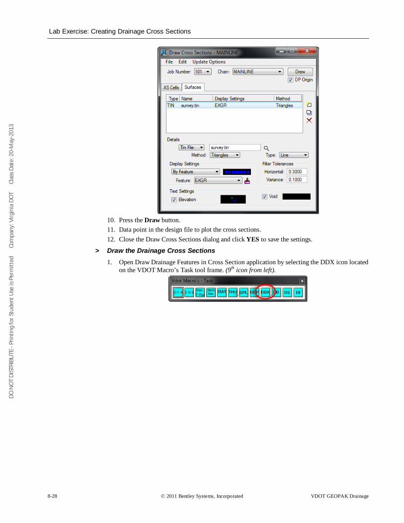
DO N
OT
DIST
RIBU
TE -
Prin
ting
for S
tude
nt U
se is
Per
mitt
ed
Co
mpa
ny: V
irgin
ia D
OT
C
lass
Dat
e: 2
0-M
ay-2
013
Lab Exercise: Creating Drainage Cross Sections
8-28 © 2011 Bentley Systems, Incorporated VDOT GEOPAK Drainage
10. Press the Draw button. 11. Data point in the design file to plot the cross sections. 12. Close the Draw Cross Sections dialog and click YES to save the settings.
> Draw the Drainage Cross Sections 1. Open Draw Drainage Features in Cross Section application by selecting the DDX icon located
on the VDOT Macro’s Task tool frame. (9th icon from left).
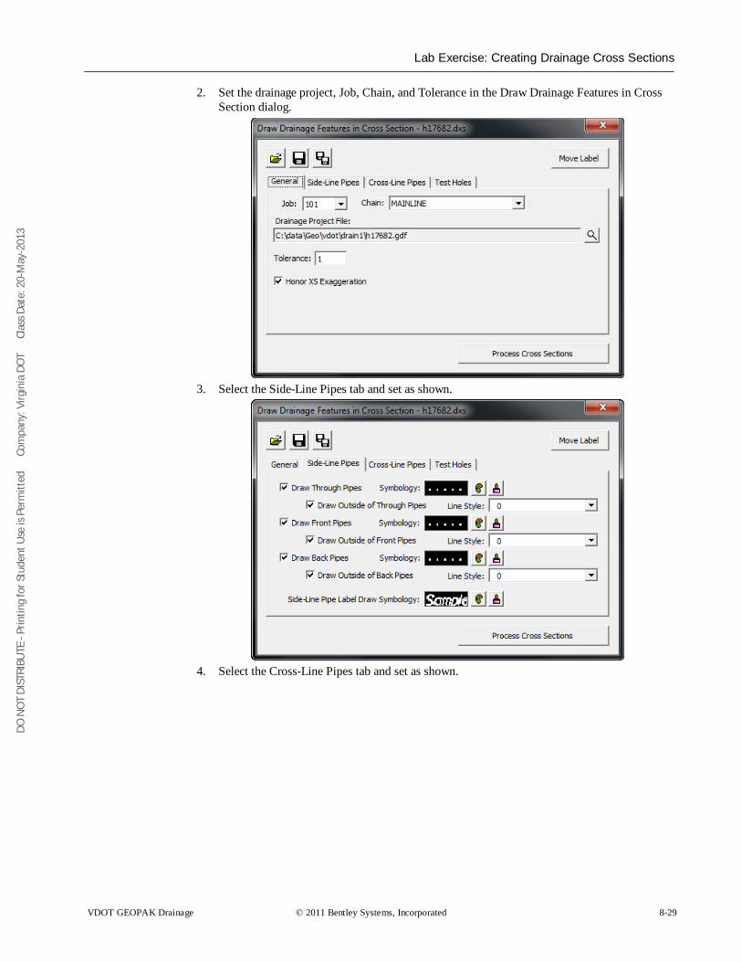
DO N
OT
DIST
RIBU
TE -
Prin
ting
for S
tude
nt U
se is
Per
mitt
ed
Co
mpa
ny: V
irgin
ia D
OT
C
lass
Dat
e: 2
0-M
ay-2
013
Lab Exercise: Creating Drainage Cross Sections
VDOT GEOPAK Drainage © 2011 Bentley Systems, Incorporated 8-29
2. Set the drainage project, Job, Chain, and Tolerance in the Draw Drainage Features in Cross Section dialog.
3. Select the Side-Line Pipes tab and set as shown.
4. Select the Cross-Line Pipes tab and set as shown.
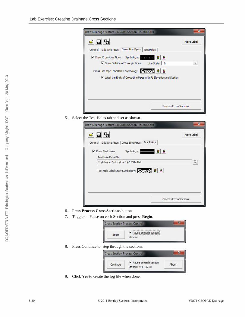
DO N
OT
DIST
RIBU
TE -
Prin
ting
for S
tude
nt U
se is
Per
mitt
ed
Co
mpa
ny: V
irgin
ia D
OT
C
lass
Dat
e: 2
0-M
ay-2
013
Lab Exercise: Creating Drainage Cross Sections
8-30 © 2011 Bentley Systems, Incorporated VDOT GEOPAK Drainage
5. Select the Test Holes tab and set as shown.
6. Press Process Cross Sections button 7. Toggle on Pause on each Section and press Begin.
8. Press Continue to step through the sections.
9. Click Yes to create the log file when done.
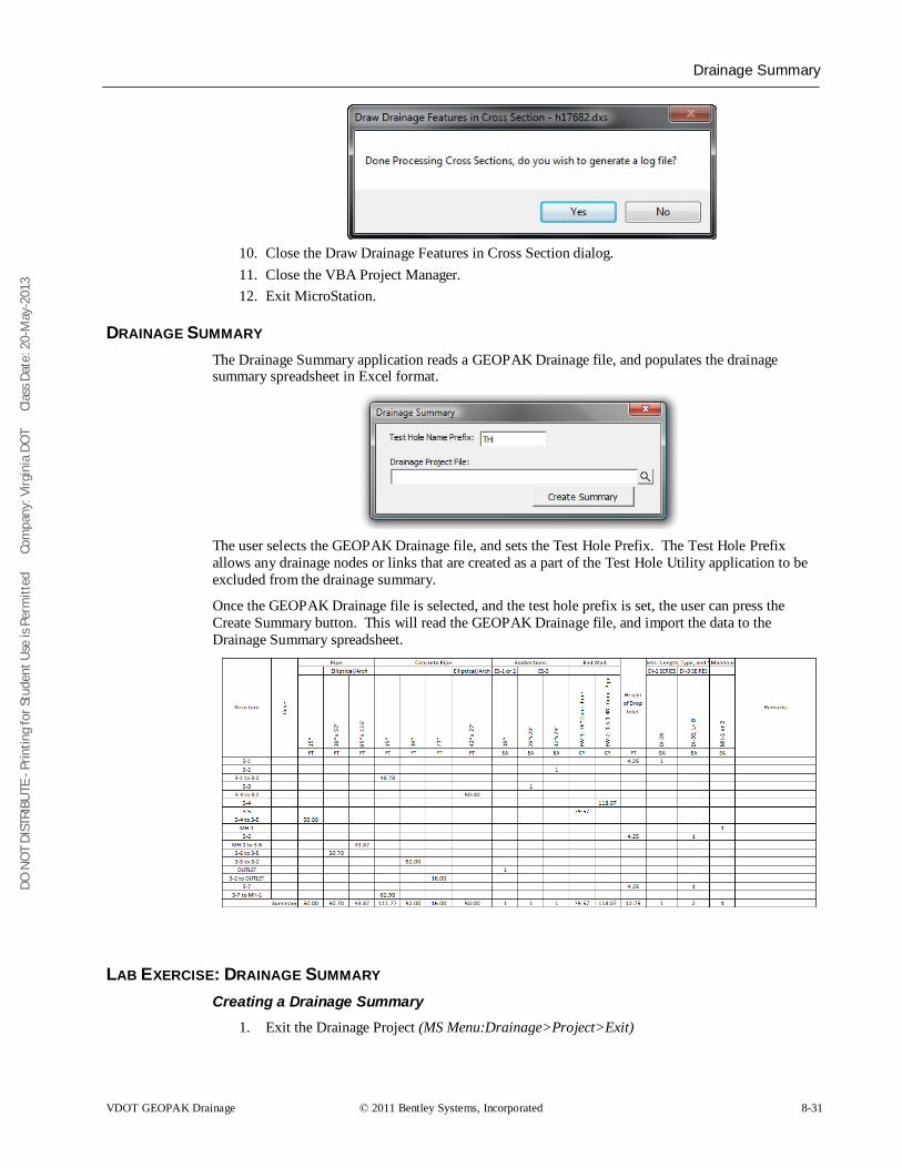
DO N
OT
DIST
RIBU
TE -
Prin
ting
for S
tude
nt U
se is
Per
mitt
ed
Co
mpa
ny: V
irgin
ia D
OT
C
lass
Dat
e: 2
0-M
ay-2
013
Drainage Summary
VDOT GEOPAK Drainage © 2011 Bentley Systems, Incorporated 8-31
10. Close the Draw Drainage Features in Cross Section dialog. 11. Close the VBA Project Manager. 12. Exit MicroStation.
DRAINAGE SUMMARY The Drainage Summary application reads a GEOPAK Drainage file, and populates the drainage summary spreadsheet in Excel format.
The user selects the GEOPAK Drainage file, and sets the Test Hole Prefix. The Test Hole Prefix allows any drainage nodes or links that are created as a part of the Test Hole Utility application to be excluded from the drainage summary.
Once the GEOPAK Drainage file is selected, and the test hole prefix is set, the user can press the Create Summary button. This will read the GEOPAK Drainage file, and import the data to the Drainage Summary spreadsheet.
LAB EXERCISE: DRAINAGE SUMMARY Creating a Drainage Summary
1. Exit the Drainage Project (MS Menu:Drainage>Project>Exit)
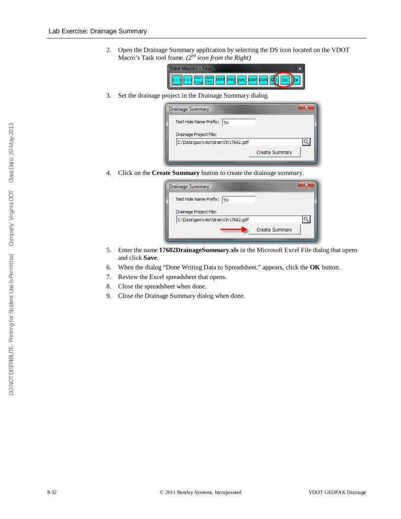
DO N
OT
DIST
RIBU
TE -
Prin
ting
for S
tude
nt U
se is
Per
mitt
ed
Co
mpa
ny: V
irgin
ia D
OT
C
lass
Dat
e: 2
0-M
ay-2
013
Lab Exercise: Drainage Summary
8-32 © 2011 Bentley Systems, Incorporated VDOT GEOPAK Drainage
2. Open the Drainage Summary application by selecting the DS icon located on the VDOT Macro’s Task tool frame. (2nd icon from the Right)
3. Set the drainage project in the Drainage Summary dialog.
4. Click on the Create Summary button to create the drainage summary.
5. Enter the name 17682DrainageSummary.xls in the Microsoft Excel File dialog that opens
and click Save. 6. When the dialog “Done Writing Data to Spreadsheet.” appears, click the OK button. 7. Review the Excel spreadsheet that opens. 8. Close the spreadsheet when done. 9. Close the Drainage Summary dialog when done.
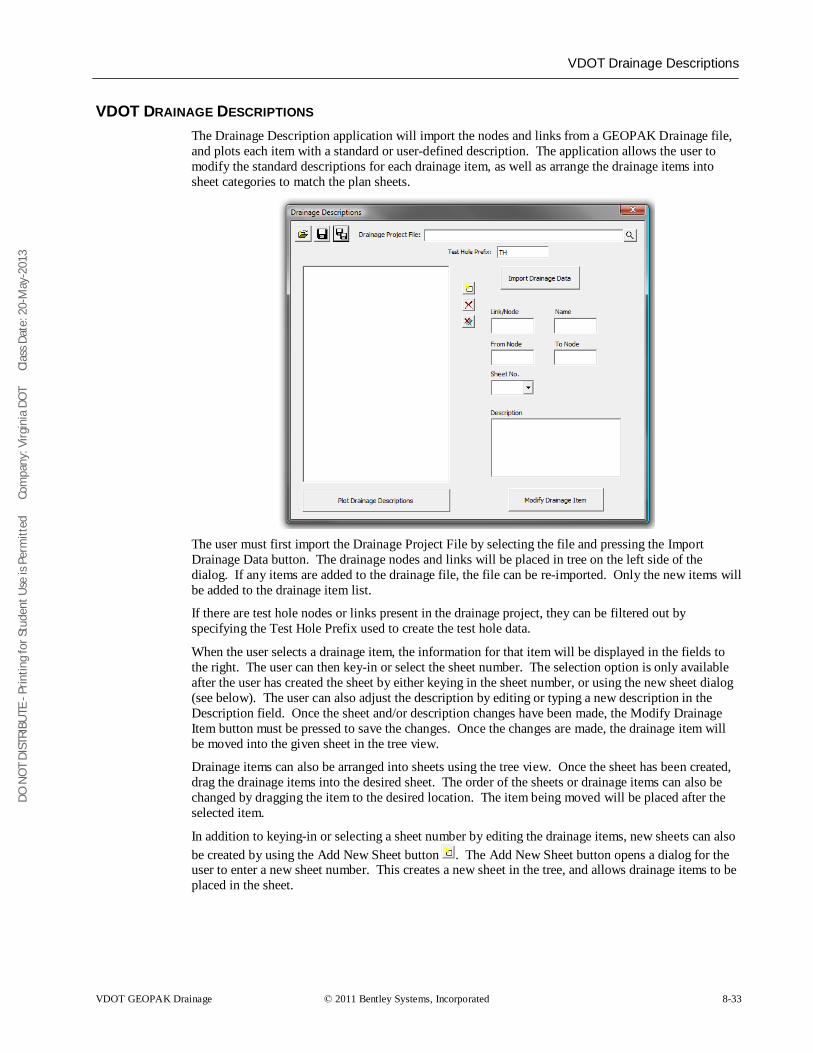
DO N
OT
DIST
RIBU
TE -
Prin
ting
for S
tude
nt U
se is
Per
mitt
ed
Co
mpa
ny: V
irgin
ia D
OT
C
lass
Dat
e: 2
0-M
ay-2
013
VDOT Drainage Descriptions
VDOT GEOPAK Drainage © 2011 Bentley Systems, Incorporated 8-33
VDOT DRAINAGE DESCRIPTIONS The Drainage Description application will import the nodes and links from a GEOPAK Drainage file, and plots each item with a standard or user-defined description. The application allows the user to modify the standard descriptions for each drainage item, as well as arrange the drainage items into sheet categories to match the plan sheets.
The user must first import the Drainage Project File by selecting the file and pressing the Import Drainage Data button. The drainage nodes and links will be placed in tree on the left side of the dialog. If any items are added to the drainage file, the file can be re-imported. Only the new items will be added to the drainage item list.
If there are test hole nodes or links present in the drainage project, they can be filtered out by specifying the Test Hole Prefix used to create the test hole data.
When the user selects a drainage item, the information for that item will be displayed in the fields to the right. The user can then key-in or select the sheet number. The selection option is only available after the user has created the sheet by either keying in the sheet number, or using the new sheet dialog (see below). The user can also adjust the description by editing or typing a new description in the Description field. Once the sheet and/or description changes have been made, the Modify Drainage Item button must be pressed to save the changes. Once the changes are made, the drainage item will be moved into the given sheet in the tree view.
Drainage items can also be arranged into sheets using the tree view. Once the sheet has been created, drag the drainage items into the desired sheet. The order of the sheets or drainage items can also be changed by dragging the item to the desired location. The item being moved will be placed after the selected item.
In addition to keying-in or selecting a sheet number by editing the drainage items, new sheets can also be created by using the Add New Sheet button . The Add New Sheet button opens a dialog for the user to enter a new sheet number. This creates a new sheet in the tree, and allows drainage items to be placed in the sheet.
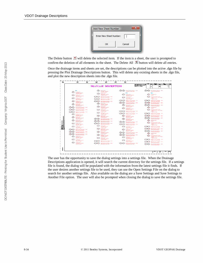
DO N
OT
DIST
RIBU
TE -
Prin
ting
for S
tude
nt U
se is
Per
mitt
ed
Co
mpa
ny: V
irgin
ia D
OT
C
lass
Dat
e: 2
0-M
ay-2
013
VDOT Drainage Descriptions
8-34 © 2011 Bentley Systems, Incorporated VDOT GEOPAK Drainage
The Delete button will delete the selected item. If the item is a sheet, the user is prompted to confirm the deletion of all elements in the sheet. The Delete All button will delete all entries.
Once the drainage items and sheets are set, the descriptions can be plotted into the active .dgn file by pressing the Plot Drainage Descriptions button. This will delete any existing sheets in the .dgn file, and plot the new description sheets into the .dgn file.
The user has the opportunity to save the dialog settings into a settings file. When the Drainage Descriptions application is opened, it will search the current directory for the settings file. If a settings file is found, the dialog will be populated with the information from the latest settings file it finds. If the user desires another settings file to be used, they can use the Open Settings File on the dialog to search for another settings file. Also available on the dialog are a Save Settings and Save Settings to Another File option. The user will also be prompted when closing the dialog to save the settings file.
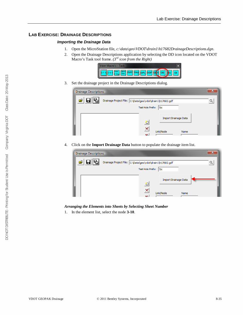
DO N
OT
DIST
RIBU
TE -
Prin
ting
for S
tude
nt U
se is
Per
mitt
ed
Co
mpa
ny: V
irgin
ia D
OT
C
lass
Dat
e: 2
0-M
ay-2
013
Lab Exercise: Drainage Descriptions
VDOT GEOPAK Drainage © 2011 Bentley Systems, Incorporated 8-35
LAB EXERCISE: DRAINAGE DESCRIPTIONS Importing the Drainage Data
1. Open the MicroStation file, c:\data\geo\VDOT\drain1\h17682DrainageDescriptions.dgn. 2. Open the Drainage Descriptions application by selecting the DD icon located on the VDOT
Macro’s Task tool frame. (3rd icon from the Right)
3. Set the drainage project in the Drainage Descriptions dialog.
4. Click on the Import Drainage Data button to populate the drainage item list.
Arranging the Elements into Sheets by Selecting Sheet Number 1. In the element list, select the node 3-10.
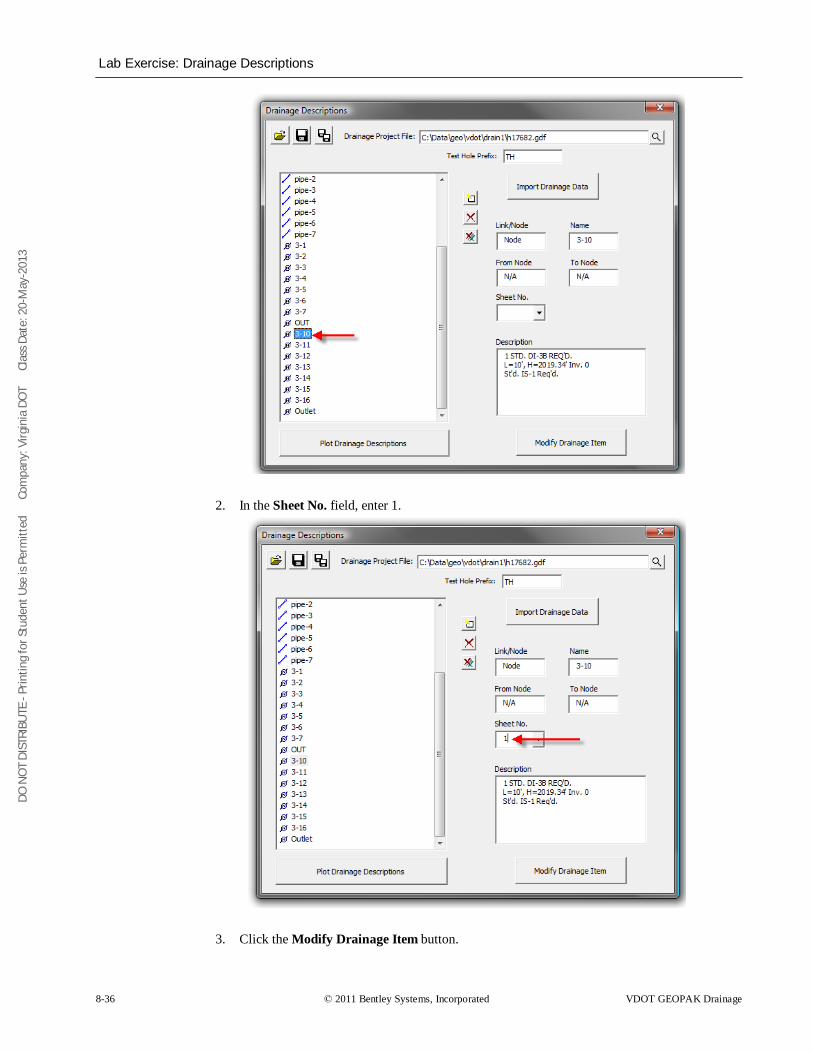
DO N
OT
DIST
RIBU
TE -
Prin
ting
for S
tude
nt U
se is
Per
mitt
ed
Co
mpa
ny: V
irgin
ia D
OT
C
lass
Dat
e: 2
0-M
ay-2
013
Lab Exercise: Drainage Descriptions
8-36 © 2011 Bentley Systems, Incorporated VDOT GEOPAK Drainage
2. In the Sheet No. field, enter 1.
3. Click the Modify Drainage Item button.
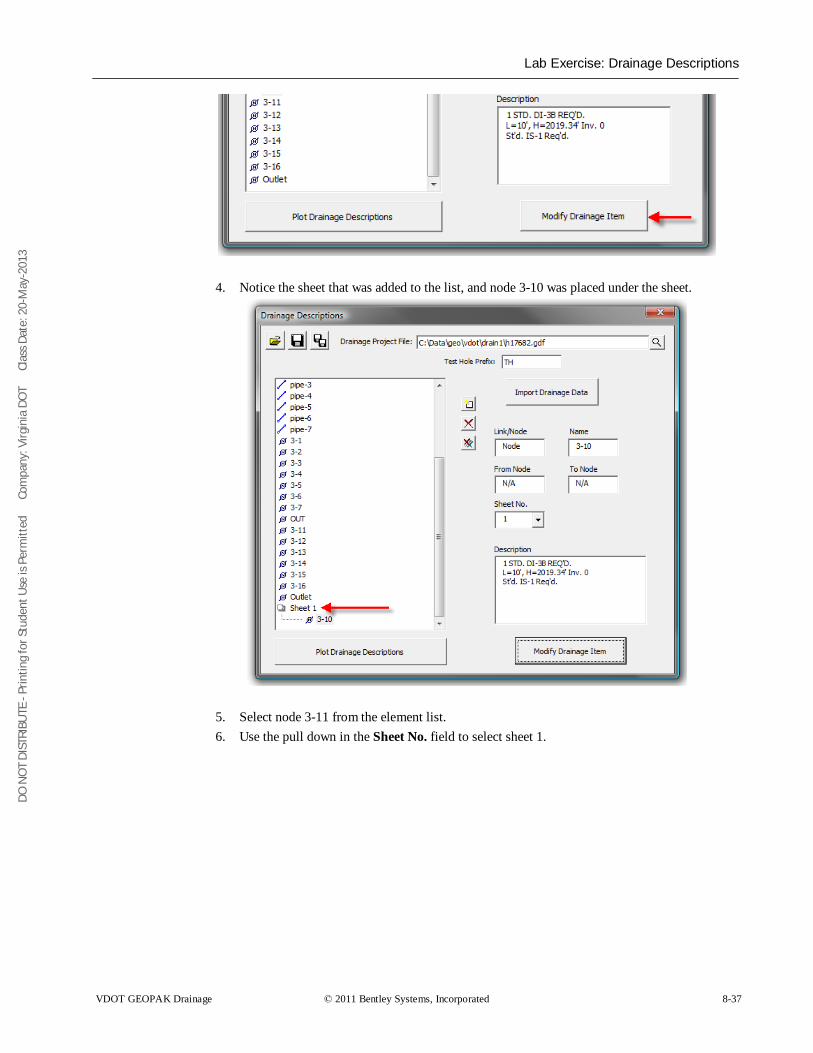
DO N
OT
DIST
RIBU
TE -
Prin
ting
for S
tude
nt U
se is
Per
mitt
ed
Co
mpa
ny: V
irgin
ia D
OT
C
lass
Dat
e: 2
0-M
ay-2
013
Lab Exercise: Drainage Descriptions
VDOT GEOPAK Drainage © 2011 Bentley Systems, Incorporated 8-37
4. Notice the sheet that was added to the list, and node 3-10 was placed under the sheet.
5. Select node 3-11 from the element list. 6. Use the pull down in the Sheet No. field to select sheet 1.
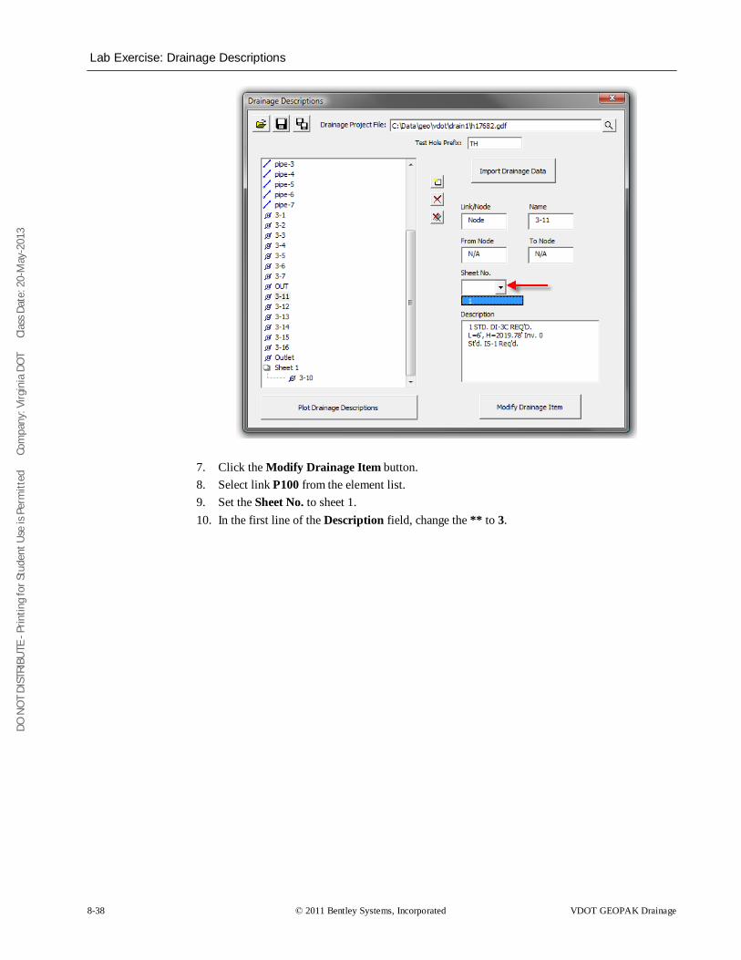
DO N
OT
DIST
RIBU
TE -
Prin
ting
for S
tude
nt U
se is
Per
mitt
ed
Co
mpa
ny: V
irgin
ia D
OT
C
lass
Dat
e: 2
0-M
ay-2
013
Lab Exercise: Drainage Descriptions
8-38 © 2011 Bentley Systems, Incorporated VDOT GEOPAK Drainage
7. Click the Modify Drainage Item button. 8. Select link P100 from the element list. 9. Set the Sheet No. to sheet 1. 10. In the first line of the Description field, change the ** to 3.
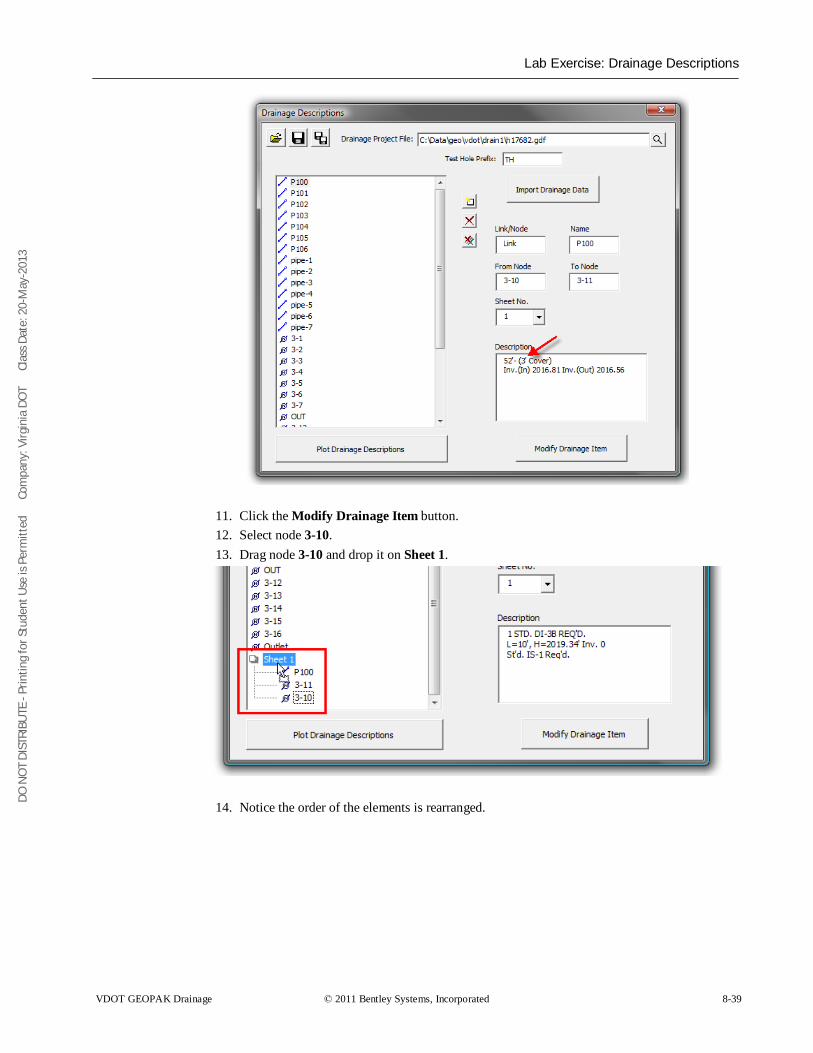
DO N
OT
DIST
RIBU
TE -
Prin
ting
for S
tude
nt U
se is
Per
mitt
ed
Co
mpa
ny: V
irgin
ia D
OT
C
lass
Dat
e: 2
0-M
ay-2
013
Lab Exercise: Drainage Descriptions
VDOT GEOPAK Drainage © 2011 Bentley Systems, Incorporated 8-39
11. Click the Modify Drainage Item button. 12. Select node 3-10. 13. Drag node 3-10 and drop it on Sheet 1.
14. Notice the order of the elements is rearranged.
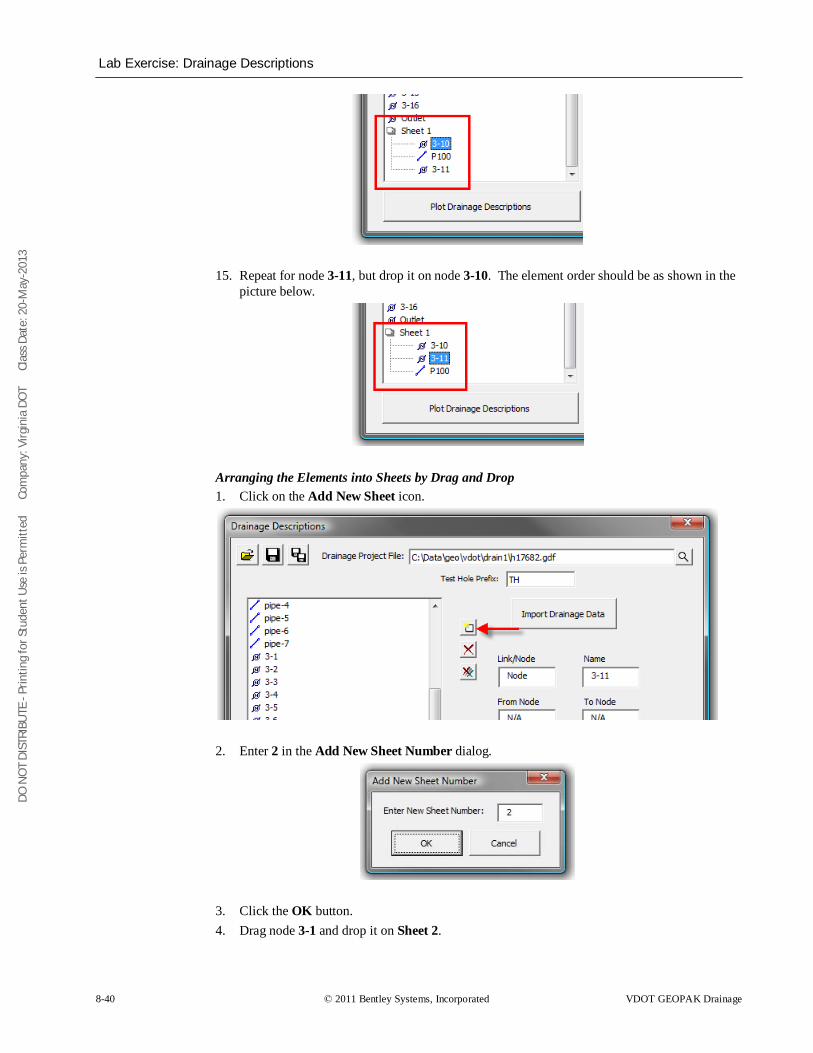
DO N
OT
DIST
RIBU
TE -
Prin
ting
for S
tude
nt U
se is
Per
mitt
ed
Co
mpa
ny: V
irgin
ia D
OT
C
lass
Dat
e: 2
0-M
ay-2
013
Lab Exercise: Drainage Descriptions
8-40 © 2011 Bentley Systems, Incorporated VDOT GEOPAK Drainage
15. Repeat for node 3-11, but drop it on node 3-10. The element order should be as shown in the picture below.
Arranging the Elements into Sheets by Drag and Drop 1. Click on the Add New Sheet icon.
2. Enter 2 in the Add New Sheet Number dialog.
3. Click the OK button. 4. Drag node 3-1 and drop it on Sheet 2.
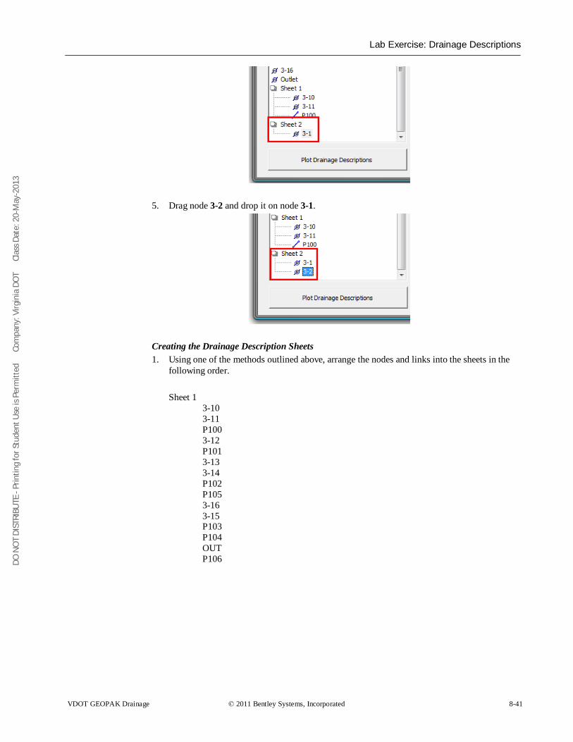
DO N
OT
DIST
RIBU
TE -
Prin
ting
for S
tude
nt U
se is
Per
mitt
ed
Co
mpa
ny: V
irgin
ia D
OT
C
lass
Dat
e: 2
0-M
ay-2
013
Lab Exercise: Drainage Descriptions
VDOT GEOPAK Drainage © 2011 Bentley Systems, Incorporated 8-41
5. Drag node 3-2 and drop it on node 3-1.
Creating the Drainage Description Sheets 1. Using one of the methods outlined above, arrange the nodes and links into the sheets in the
following order.
Sheet 1 3-10 3-11 P100 3-12 P101 3-13 3-14 P102 P105 3-16 3-15 P103 P104 OUT P106
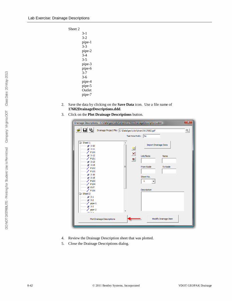
DO N
OT
DIST
RIBU
TE -
Prin
ting
for S
tude
nt U
se is
Per
mitt
ed
Co
mpa
ny: V
irgin
ia D
OT
C
lass
Dat
e: 2
0-M
ay-2
013
Lab Exercise: Drainage Descriptions
8-42 © 2011 Bentley Systems, Incorporated VDOT GEOPAK Drainage
Sheet 2 3-1 3-2 pipe-1 3-3 pipe-2 3-4 3-5 pipe-3 pipe-6 3-7 3-6 pipe-4 pipe-5 Outlet pipe-7
2. Save the data by clicking on the Save Data icon. Use a file name of 17682DrainageDescriptions.ddd.
3. Click on the Plot Drainage Descriptions button.
4. Review the Drainage Description sheet that was plotted. 5. Close the Drainage Descriptions dialog.
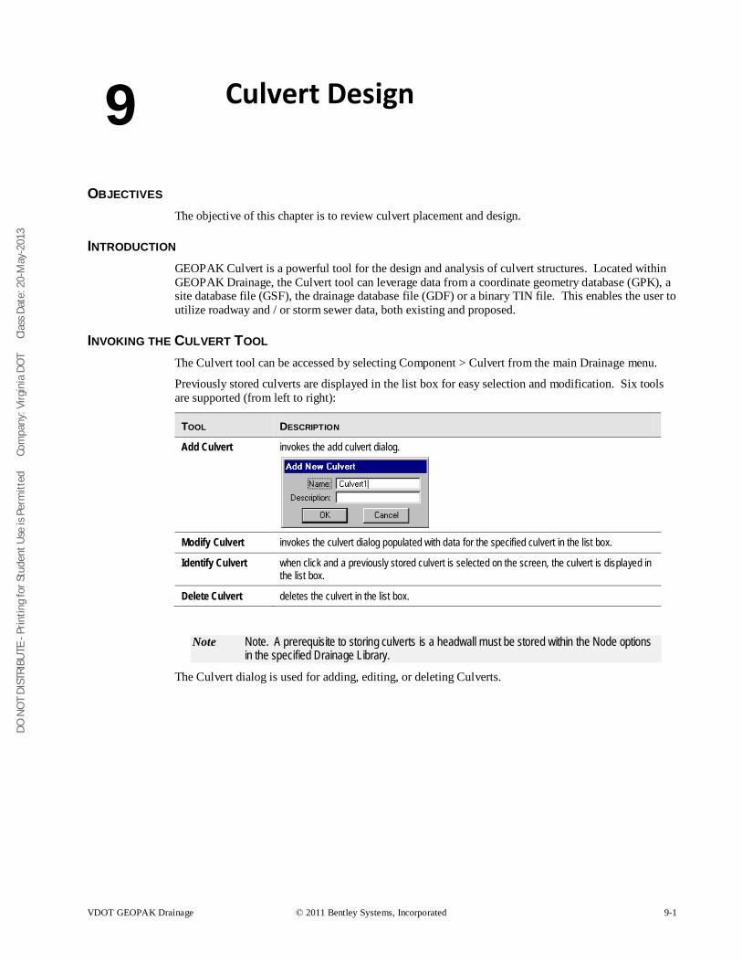
DO N
OT
DIST
RIBU
TE -
Prin
ting
for S
tude
nt U
se is
Per
mitt
ed
Co
mpa
ny: V
irgin
ia D
OT
C
lass
Dat
e: 2
0-M
ay-2
013
VDOT GEOPAK Drainage © 2011 Bentley Systems, Incorporated 9-1
Culvert Design
OBJECTIVES The objective of this chapter is to review culvert placement and design.
INTRODUCTION GEOPAK Culvert is a powerful tool for the design and analysis of culvert structures. Located within GEOPAK Drainage, the Culvert tool can leverage data from a coordinate geometry database (GPK), a site database file (GSF), the drainage database file (GDF) or a binary TIN file. This enables the user to utilize roadway and / or storm sewer data, both existing and proposed.
INVOKING THE CULVERT TOOL The Culvert tool can be accessed by selecting Component > Culvert from the main Drainage menu.
Previously stored culverts are displayed in the list box for easy selection and modification. Six tools are supported (from left to right):
TOOL DESCRIPTION
Add Culvert invokes the add culvert dialog.
Modify Culvert invokes the culvert dialog populated with data for the specified culvert in the list box.
Identify Culvert when click and a previously stored culvert is selected on the screen, the culvert is displayed in the list box.
Delete Culvert deletes the culvert in the list box.
Note Note. A prerequisite to storing culverts is a headwall must be stored within the Node options in the specified Drainage Library.
The Culvert dialog is used for adding, editing, or deleting Culverts.
9
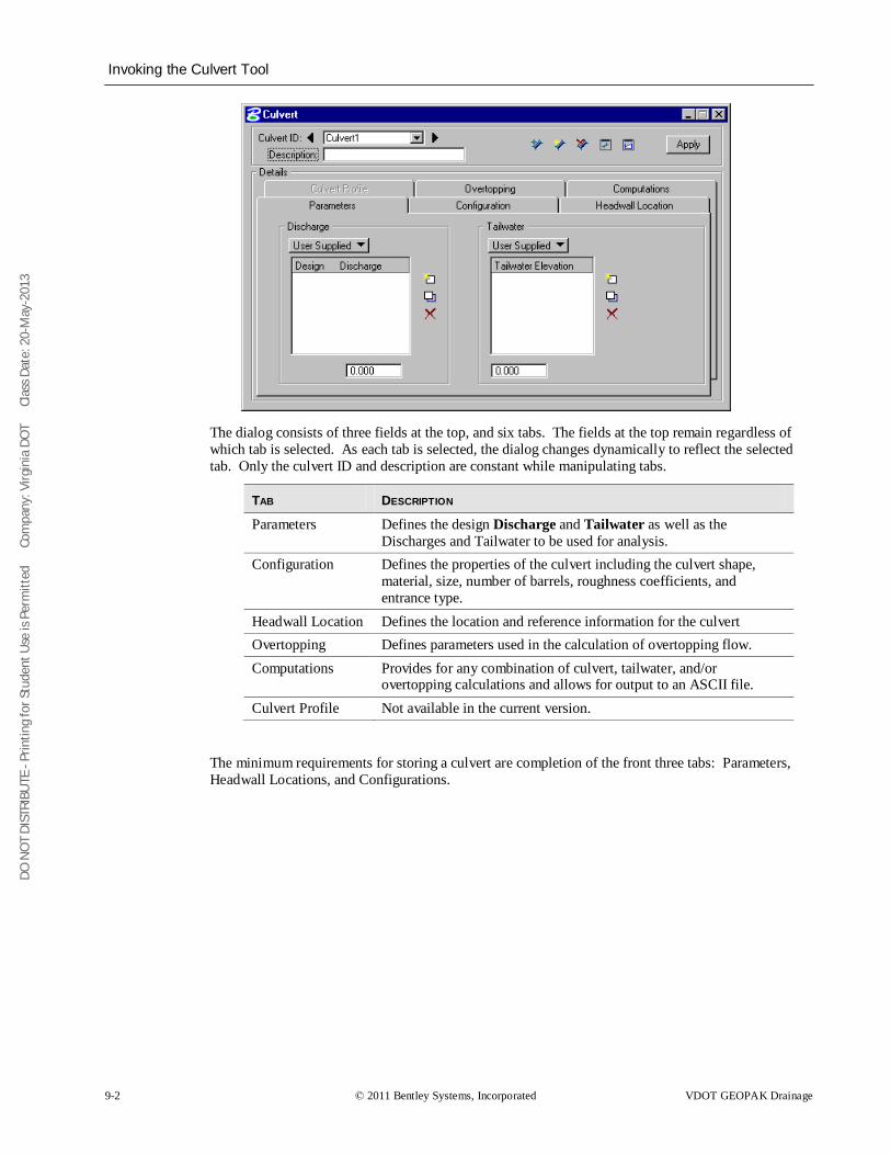
DO N
OT
DIST
RIBU
TE -
Prin
ting
for S
tude
nt U
se is
Per
mitt
ed
Co
mpa
ny: V
irgin
ia D
OT
C
lass
Dat
e: 2
0-M
ay-2
013
Invoking the Culvert Tool
9-2 © 2011 Bentley Systems, Incorporated VDOT GEOPAK Drainage
The dialog consists of three fields at the top, and six tabs. The fields at the top remain regardless of which tab is selected. As each tab is selected, the dialog changes dynamically to reflect the selected tab. Only the culvert ID and description are constant while manipulating tabs.
TAB DESCRIPTION
Parameters Defines the design Discharge and Tailwater as well as the Discharges and Tailwater to be used for analysis.
Configuration Defines the properties of the culvert including the culvert shape, material, size, number of barrels, roughness coefficients, and entrance type.
Headwall Location Defines the location and reference information for the culvert Overtopping Defines parameters used in the calculation of overtopping flow. Computations Provides for any combination of culvert, tailwater, and/or
overtopping calculations and allows for output to an ASCII file. Culvert Profile Not available in the current version.
The minimum requirements for storing a culvert are completion of the front three tabs: Parameters, Headwall Locations, and Configurations.
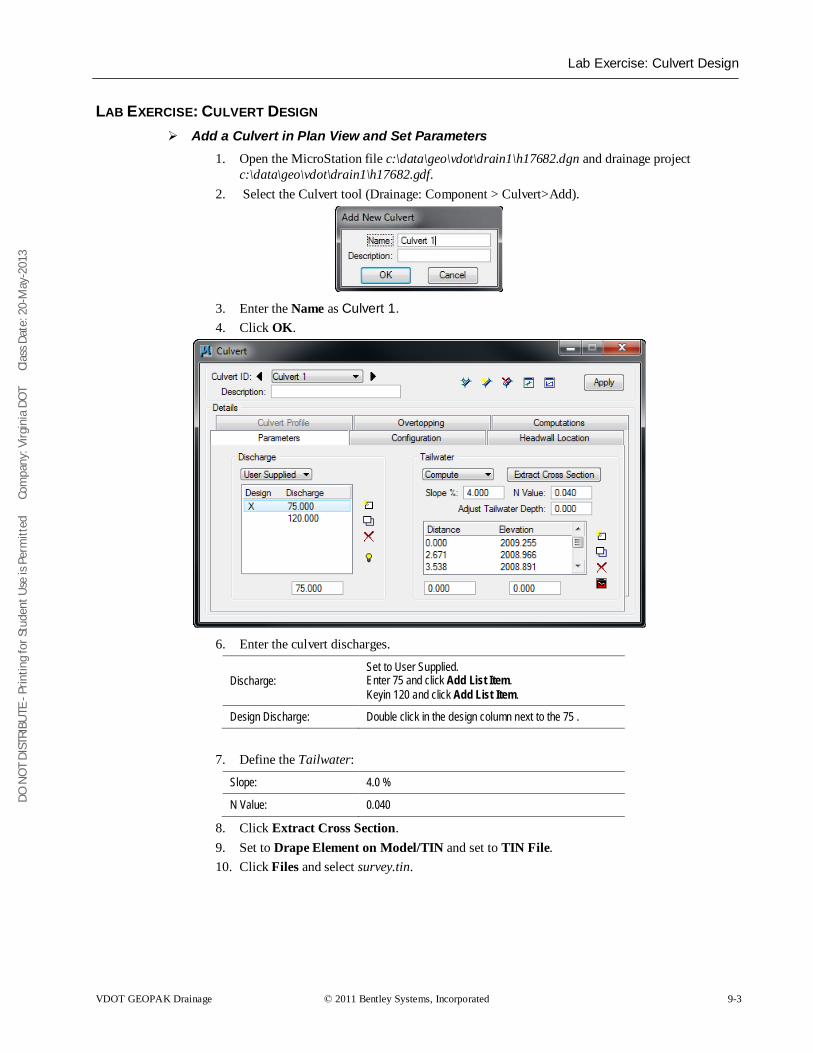
DO N
OT
DIST
RIBU
TE -
Prin
ting
for S
tude
nt U
se is
Per
mitt
ed
Co
mpa
ny: V
irgin
ia D
OT
C
lass
Dat
e: 2
0-M
ay-2
013
Lab Exercise: Culvert Design
VDOT GEOPAK Drainage © 2011 Bentley Systems, Incorporated 9-3
LAB EXERCISE: CULVERT DESIGN Add a Culvert in Plan View and Set Parameters
1. Open the MicroStation file c:\data\geo\vdot\drain1\h17682.dgn and drainage project c:\data\geo\vdot\drain1\h17682.gdf.
2. Select the Culvert tool (Drainage: Component > Culvert>Add).
3. Enter the Name as Culvert 1.4. Click OK.
6. Enter the culvert discharges.
Discharge: Set to User Supplied. Enter 75 and click Add List Item. Keyin 120 and click Add List Item.
Design Discharge: Double click in the design column next to the 75 .
7. Define the Tailwater:
Slope: 4.0 %
N Value: 0.040
8. Click Extract Cross Section. 9. Set to Drape Element on Model/TIN and set to TIN File. 10. Click Files and select survey.tin.
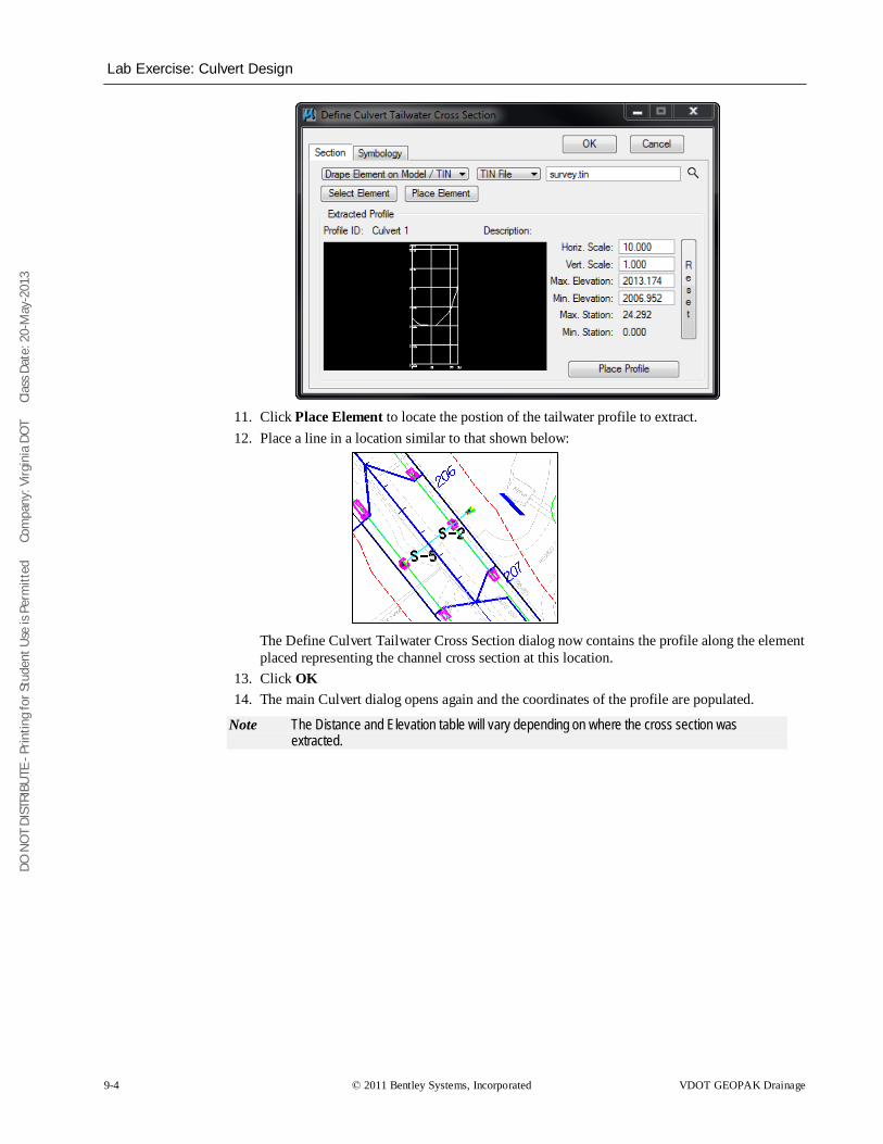
DO N
OT
DIST
RIBU
TE -
Prin
ting
for S
tude
nt U
se is
Per
mitt
ed
Co
mpa
ny: V
irgin
ia D
OT
C
lass
Dat
e: 2
0-M
ay-2
013
Lab Exercise: Culvert Design
9-4 © 2011 Bentley Systems, Incorporated VDOT GEOPAK Drainage
11. Click Place Element to locate the postion of the tailwater profile to extract. 12. Place a line in a location similar to that shown below:
The Define Culvert Tailwater Cross Section dialog now contains the profile along the element placed representing the channel cross section at this location.
13. Click OK 14. The main Culvert dialog opens again and the coordinates of the profile are populated.
Note The Distance and Elevation table will vary depending on where the cross section was extracted.
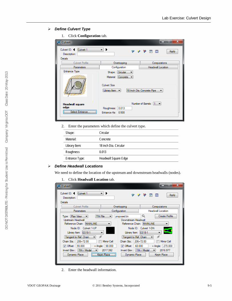
DO N
OT
DIST
RIBU
TE -
Prin
ting
for S
tude
nt U
se is
Per
mitt
ed
Co
mpa
ny: V
irgin
ia D
OT
C
lass
Dat
e: 2
0-M
ay-2
013
Lab Exercise: Culvert Design
VDOT GEOPAK Drainage © 2011 Bentley Systems, Incorporated 9-5
Define Culvert Type
1. Click Configuration tab.
2. Enter the parameters which define the culvert type.
Shape: Circular
Material: Concrete
Library Item: 18 inch Dia. Circular
Roughness 0.013
Entrance Type: Headwall Square Edge
Define Headwall Locations We need to define the location of the upstream and downstream headwalls (nodes).
1. Click Headwall Location tab.
2. Enter the headwall information.
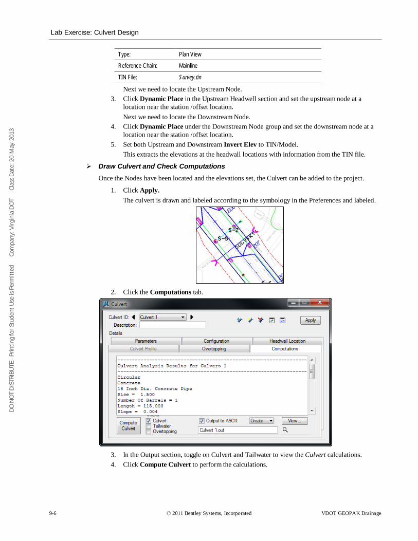
DO N
OT
DIST
RIBU
TE -
Prin
ting
for S
tude
nt U
se is
Per
mitt
ed
Co
mpa
ny: V
irgin
ia D
OT
C
lass
Dat
e: 2
0-M
ay-2
013
Lab Exercise: Culvert Design
9-6 © 2011 Bentley Systems, Incorporated VDOT GEOPAK Drainage
Type: Plan View
Reference Chain: Mainline
TIN File: Survey.tin
Next we need to locate the Upstream Node. 3. Click Dynamic Place in the Upstream Headwell section and set the upstream node at a
location near the station /offset location. Next we need to locate the Downstream Node.
4. Click Dynamic Place under the Downstream Node group and set the downstream node at a location near the station /offset location.
5. Set both Upstream and Downstream Invert Elev to TIN/Model. This extracts the elevations at the headwall locations with information from the TIN file.
Draw Culvert and Check Computations Once the Nodes have been located and the elevations set, the Culvert can be added to the project.
1. Click Apply. The culvert is drawn and labeled according to the symbology in the Preferences and labeled.
2. Click the Computations tab.
3. In the Output section, toggle on Culvert and Tailwater to view the Culvert calculations. 4. Click Compute Culvert to perform the calculations.
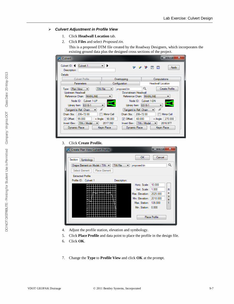
DO N
OT
DIST
RIBU
TE -
Prin
ting
for S
tude
nt U
se is
Per
mitt
ed
Co
mpa
ny: V
irgin
ia D
OT
C
lass
Dat
e: 2
0-M
ay-2
013
Lab Exercise: Culvert Design
VDOT GEOPAK Drainage © 2011 Bentley Systems, Incorporated 9-7
Culvert Adjustment in Profile View
1. Click Headwall Location tab. 2. Click Files and select Proposed.tin.
This is a proposed DTM file created by the Roadway Designers, which incorporates the existing ground data plus the designed cross sections of the project.
3. Click Create Profile.
4. Adjust the profile station, elevation and symbology. 5. Click Place Profile and data point to place the profile in the design file. 6. Click OK. 7. Change the Type to Profile View and click OK at the prompt.
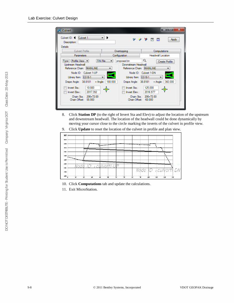
DO N
OT
DIST
RIBU
TE -
Prin
ting
for S
tude
nt U
se is
Per
mitt
ed
Co
mpa
ny: V
irgin
ia D
OT
C
lass
Dat
e: 2
0-M
ay-2
013
Lab Exercise: Culvert Design
9-8 © 2011 Bentley Systems, Incorporated VDOT GEOPAK Drainage
8. Click Station DP (to the right of Invert Sta and Elev) to adjust the location of the upstream
and downstream headwall. The location of the headwall could be done dynamically by moving your cursor close to the circle marking the inverts of the culvert in profile view.
9. Click Update to reset the location of the culvert in profile and plan view.
10. Click Computations tab and update the calculations. 11. Exit MicroStation.
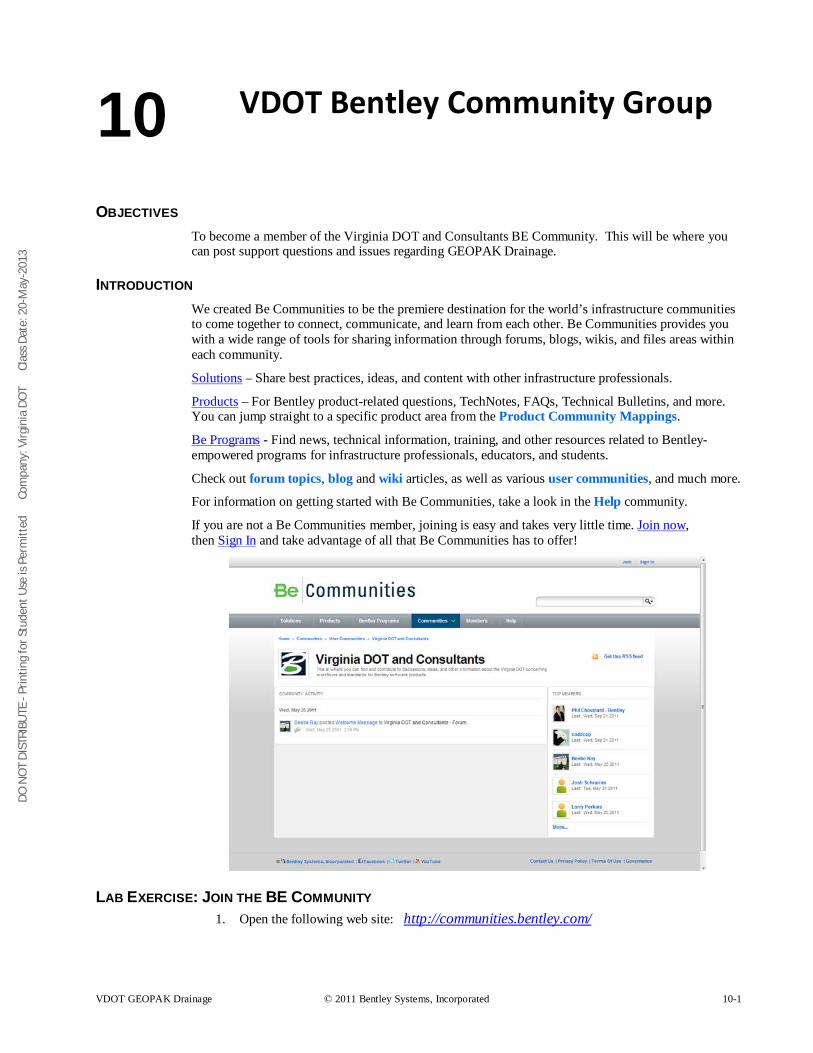
DO N
OT
DIST
RIBU
TE -
Prin
ting
for S
tude
nt U
se is
Per
mitt
ed
Co
mpa
ny: V
irgin
ia D
OT
C
lass
Dat
e: 2
0-M
ay-2
013
VDOT GEOPAK Drainage © 2011 Bentley Systems, Incorporated 10-1
VDOT Bentley Community Group
OBJECTIVES To become a member of the Virginia DOT and Consultants BE Community. This will be where you can post support questions and issues regarding GEOPAK Drainage.
INTRODUCTION We created Be Communities to be the premiere destination for the world’s infrastructure communities to come together to connect, communicate, and learn from each other. Be Communities provides you with a wide range of tools for sharing information through forums, blogs, wikis, and files areas within each community.
Solutions – Share best practices, ideas, and content with other infrastructure professionals.
Products – For Bentley product-related questions, TechNotes, FAQs, Technical Bulletins, and more. You can jump straight to a specific product area from the Product Community Mappings.
Be Programs - Find news, technical information, training, and other resources related to Bentley-empowered programs for infrastructure professionals, educators, and students.
Check out forum topics, blog and wiki articles, as well as various user communities, and much more.
For information on getting started with Be Communities, take a look in the Help community.
If you are not a Be Communities member, joining is easy and takes very little time. Join now, then Sign In and take advantage of all that Be Communities has to offer!
LAB EXERCISE: JOIN THE BE COMMUNITY 1. Open the following web site: http://communities.bentley.com/
10
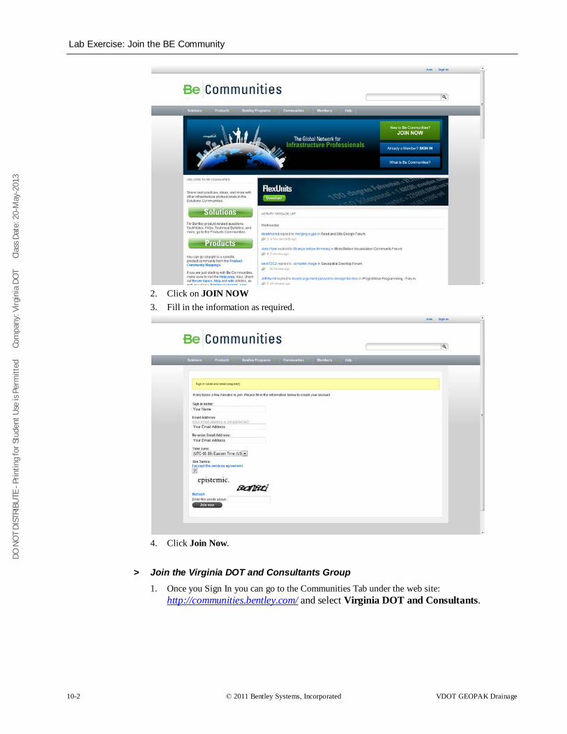
DO N
OT
DIST
RIBU
TE -
Prin
ting
for S
tude
nt U
se is
Per
mitt
ed
Co
mpa
ny: V
irgin
ia D
OT
C
lass
Dat
e: 2
0-M
ay-2
013
Lab Exercise: Join the BE Community
10-2 © 2011 Bentley Systems, Incorporated VDOT GEOPAK Drainage
2. Click on JOIN NOW 3. Fill in the information as required.
4. Click Join Now.
> Join the Virginia DOT and Consultants Group 1. Once you Sign In you can go to the Communities Tab under the web site:
http://communities.bentley.com/ and select Virginia DOT and Consultants.
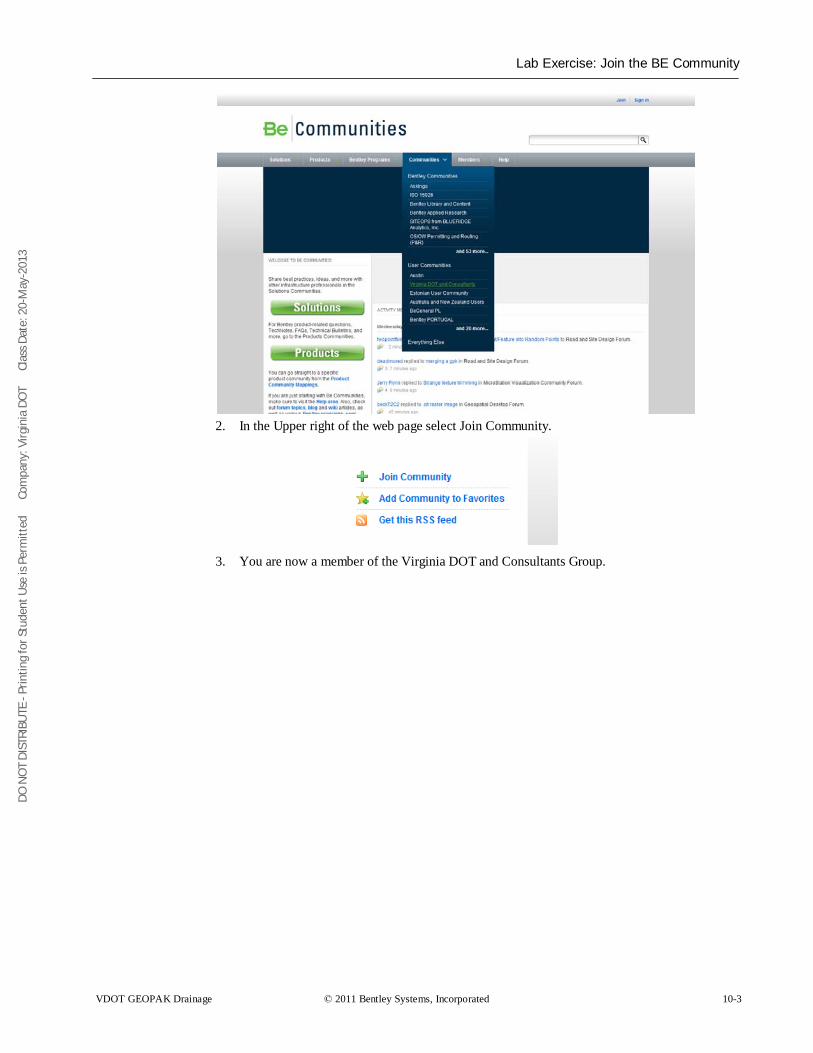
DO N
OT
DIST
RIBU
TE -
Prin
ting
for S
tude
nt U
se is
Per
mitt
ed
Co
mpa
ny: V
irgin
ia D
OT
C
lass
Dat
e: 2
0-M
ay-2
013
Lab Exercise: Join the BE Community
VDOT GEOPAK Drainage © 2011 Bentley Systems, Incorporated 10-3
2. In the Upper right of the web page select Join Community.
3. You are now a member of the Virginia DOT and Consultants Group.

DO N
OT
DIST
RIBU
TE -
Prin
ting
for S
tude
nt U
se is
Per
mitt
ed
Co
mpa
ny: V
irgin
ia D
OT
C
lass
Dat
e: 2
0-M
ay-2
013
Lab Exercise: Join the BE Community
10-4 © 2011 Bentley Systems, Incorporated VDOT GEOPAK Drainage
DO N
OT
DIST
RIBU
TE -
Prin
ting
for S
tude
nt U
se is
Per
mitt
ed
Co
mpa
ny: V
irgin
ia D
OT
C
lass
Dat
e: 2
0-M
ay-2
013
VDOT GEOPAK Drainage © 2011 Bentley Systems, Incorporated 11-1
Class Project
OBJECTIVES Using the Data Provided:
• Create and design a storm sewer system with GEOPAK Drainage. • Create a Profile of the storm sewer system. • Create Storm Tabulation and Spread Analysis for the storm sewer system.
INTRODUCTION You are starting a project and need to do the first pass design with GEOPAK Drainage. You have been provided a basic set of files from the location and design group to get started.
You are required at this stage to provide a profile of the system for review. You are also required to submit a Storm Tabulation sheet and a Spread Analysis sheet.
PROJECT FILES There are several files that have been provided. They are located on the computer hard drive. The files provided include the proposed design of the roadway, the proposed design terrain model, the existing survey and utility design files, the coordinate geometry database with alignments and profiles of the design, and the GEOPAK project manager file.
You have also been provided a blank GEOPAK Drainage file with all the necessary project preferences set up.
The files are all located in the following folder:
C:\data\geo\vdot\drain1 - end of class project\
The files included in the folder are:
1. d93144des.dgn – roadway design file
2. d93144work.dgn – superelevation shapes and pattern lines
3. d93144xspacific.dgn – proposed cross section file
4. d93144prop.tin – GEOPAK surface file
5. job101.gpk – GEOPAK coordinate geometry database
a. Alignment - Pacific
6. s93144.dgn – existing survey file
7. su93144 – existing utility file
8. h93144.dgn – blank file for hydraulic design
a. Rainfall Preferences – Loudon County
9. h93144.gdf – blank GEOPAK Drainage file for hydraulic design
10. h93144da.gdf – defined drainage areas for use on this project
11. 93144.prj – GEOPAK Project Manager file
11
DO N
OT
DIST
RIBU
TE -
Prin
ting
for S
tude
nt U
se is
Per
mitt
ed
Co
mpa
ny: V
irgin
ia D
OT
C
lass
Dat
e: 2
0-M
ay-2
013
Project Completion
11-2 © 2011 Bentley Systems, Incorporated VDOT GEOPAK Drainage
There are a few other files as well that may assist you in the layout and design of your project. All standard files specific to VDOT design and needed by the software should be automatically accessed through your VDOT workspace.
PROJECT COMPLETION Your project is considered complete when you show the instructor a profile of your system along with a storm tabulation and spread analysis.
DO N
OT
DIST
RIBU
TE -
Prin
ting
for S
tude
nt U
se is
Per
mitt
ed
Co
mpa
ny: V
irgin
ia D
OT
C
lass
Dat
e: 2
0-M
ay-2
013
VDOT GEOPAK Drainage © 2011 Bentley Systems, Incorporated 12-1
Technical Reference
OBJECTIVES • The objective of this chapter is to review the computation methods utilized by GEOPAK
Drainage.
THE RATIONAL METHOD The Rational method is the most widely used formula to calculate storm water runoff. VDOT recommends the use of that for pipe sizing, inlet capacity and spread computations.
This method uses certain assumptions that make their use only suitable for areas of less than 200 acres.
These assumptions are:
• The entire drainage area contributes to the discharge
• Rainfall intensity, measured in inches per hour, is distributed evenly in the whole drainage area.
• Rainfall intensity is at a constant rate along the entire duration of the storm. The storm duration is at least equal to the time of concentration.
• Frequency of the computed flow is of the same frequency as that of the rainfall intensity. A 5 year rainfall intensity is set to produce a 5 year peak flow or discharge.
• Coefficient of runoff is the same for all storms and probabilities of recurrence.
The rational formula is given as:
CIAQ =
Q = computed peak discharge in cubic feet per second (cfs)
C = runoff coefficient (non dimensional value)
I = intensity of storm in inches/hr.
A = drainage area in acres
The formula is not dimensionally correct as it is a result of empirical studies.
Let’s analyze in detail each component of the formula.
RUNOFF COEFFICIENT (C) The runoff coefficient is a function of the ground cover and other hydrological abstractions.
This is a dimensionless number that represents the fraction of rainfall that remains on the surface of the ground.
The runoff coefficient relates the estimated peak discharge to a theoretical maximum of 100 percent of runoff.
VDOT provides a table of runoff coefficients that depends on the slope of the terrain being analyzed and the use of it.
12
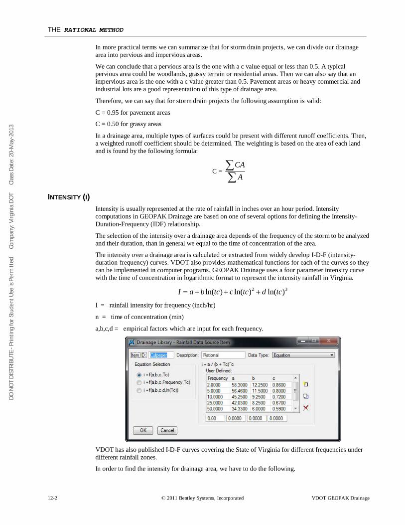
DO N
OT
DIST
RIBU
TE -
Prin
ting
for S
tude
nt U
se is
Per
mitt
ed
Co
mpa
ny: V
irgin
ia D
OT
C
lass
Dat
e: 2
0-M
ay-2
013
THE RATIONAL METHOD
12-2 © 2011 Bentley Systems, Incorporated VDOT GEOPAK Drainage
In more practical terms we can summarize that for storm drain projects, we can divide our drainage area into pervious and impervious areas.
We can conclude that a pervious area is the one with a c value equal or less than 0.5. A typical pervious area could be woodlands, grassy terrain or residential areas. Then we can also say that an impervious area is the one with a c value greater than 0.5. Pavement areas or heavy commercial and industrial lots are a good representation of this type of drainage area.
Therefore, we can say that for storm drain projects the following assumption is valid:
C = 0.95 for pavement areas
C = 0.50 for grassy areas
In a drainage area, multiple types of surfaces could be present with different runoff coefficients. Then, a weighted runoff coefficient should be determined. The weighting is based on the area of each land and is found by the following formula:
C = ∑∑
ACA
INTENSITY (I) Intensity is usually represented at the rate of rainfall in inches over an hour period. Intensity computations in GEOPAK Drainage are based on one of several options for defining the Intensity-Duration-Frequency (IDF) relationship.
The selection of the intensity over a drainage area depends of the frequency of the storm to be analyzed and their duration, than in general we equal to the time of concentration of the area.
The intensity over a drainage area is calculated or extracted from widely develop I-D-F (intensity-duration-frequency) curves. VDOT also provides mathematical functions for each of the curves so they can be implemented in computer programs. GEOPAK Drainage uses a four parameter intensity curve with the time of concentration in logarithmic format to represent the intensity rainfall in Virginia.
32 )ln()ln()ln( tcdtcctcbaI +++=
I = rainfall intensity for frequency (inch/hr)
n = time of concentration (min)
a,b,c,d = empirical factors which are input for each frequency.
VDOT has also published I-D-F curves covering the State of Virginia for different frequencies under different rainfall zones.
In order to find the intensity for drainage area, we have to do the following.
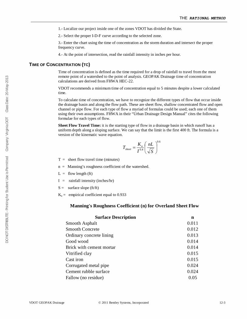
DO N
OT
DIST
RIBU
TE -
Prin
ting
for S
tude
nt U
se is
Per
mitt
ed
Co
mpa
ny: V
irgin
ia D
OT
C
lass
Dat
e: 2
0-M
ay-2
013
THE RATIONAL METHOD
VDOT GEOPAK Drainage © 2011 Bentley Systems, Incorporated 12-3
1.- Localize our project inside one of the zones VDOT has divided the State.
2.- Select the proper I-D-F curve according to the selected zone.
3.- Enter the chart using the time of concentration as the storm duration and intersect the proper frequency curve.
4.- At the point of intersection, read the rainfall intensity in inches per hour.
TIME OF CONCENTRATION (TC) Time of concentration is defined as the time required for a drop of rainfall to travel from the most remote point of a watershed to the point of analysis. GEOPAK Drainage time of concentration calculations are derived from FHWA HEC-22.
VDOT recommends a minimum time of concentration equal to 5 minutes despite a lower calculated time.
To calculate time of concentration, we have to recognize the different types of flow that occur inside the drainage basin and along the flow path. These are sheet flow, shallow concentrated flow and open channel or pipe flow. For each type of flow a myriad of formulas could be used; each one of them using their own assumptions. FHWA in their “Urban Drainage Design Manual” cites the following formulae for each types of flow.
Sheet Flow Travel Time: it is the starting type of flow in a drainage basin in which runoff has a uniform depth along a sloping surface. We can say that the limit is the first 400 ft. The formula is a version of the kinematic wave equation.
6.0
4.0
=
SnL
IKT u
sheet
T = sheet flow travel time (minutes)
n = Manning’s roughness coefficient of the watershed.
L = flow length (ft)
I = rainfall intensity (inches/hr)
S = surface slope (ft/ft)
Ku = empirical coefficient equal to 0.933
Manning's Roughness Coefficient (n) for Overland Sheet Flow
Surface Description n Smooth Asphalt 0.011 Smooth Concrete 0.012 Ordinary concrete lining 0.013 Good wood 0.014 Brick with cement mortar 0.014 Vitrified clay 0.015 Cast iron 0.015 Corrugated metal pipe 0.024 Cement rubble surface 0.024 Fallow (no residue) 0.05
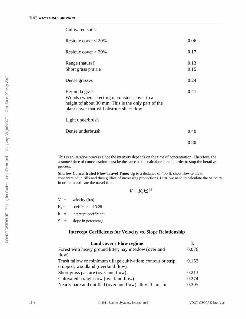
DO N
OT
DIST
RIBU
TE -
Prin
ting
for S
tude
nt U
se is
Per
mitt
ed
Co
mpa
ny: V
irgin
ia D
OT
C
lass
Dat
e: 2
0-M
ay-2
013
THE RATIONAL METHOD
12-4 © 2011 Bentley Systems, Incorporated VDOT GEOPAK Drainage
Cultivated soils:
Residue cover < 20%
Residue cover > 20%
Range (natural)
0.06
0.17
0.13 Short grass prairie
Dense grasses
Bermuda grass
0.15
0.24
0.41 Woods (when selecting n, consider cover to a height of about 30 mm. This is the only part of the plant cover that will obstruct sheet flow.
Light underbrush
Dense underbrush
0.40
0.80
This is an iterative process since the intensity depends on the time of concentration. Therefore, the assumed time of concentration must be the same as the calculated one in order to stop the iterative process.
Shallow Concentrated Flow Travel Time: Up to a distance of 400 ft, sheet flow tends to concentrated in rills and then gullies of increasing proportions. First, we need to calculate the velocity in order to estimate the travel time.
5.0kSKV u=
V = velocity (ft/s)
Ku = coefficient of 3.28
k = intercept coefficient.
S = slope in percentage
Intercept Coefficients for Velocity vs. Slope Relationship
Land cover / Flow regime k Forest with heavy ground litter; hay meadow (overland flow)
0.076
Trash fallow or minimum tillage cultivation; contour or strip cropped; woodland (overland flow).
0.152
Short grass pasture (overland flow) 0.213 Cultivated straight row (overland flow). 0.274 Nearly bare and untilled (overland flow) alluvial fans in 0.305
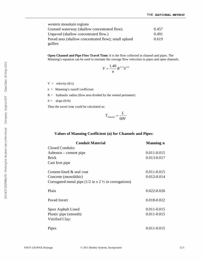
DO N
OT
DIST
RIBU
TE -
Prin
ting
for S
tude
nt U
se is
Per
mitt
ed
Co
mpa
ny: V
irgin
ia D
OT
C
lass
Dat
e: 2
0-M
ay-2
013
THE RATIONAL METHOD
VDOT GEOPAK Drainage © 2011 Bentley Systems, Incorporated 12-5
western mountain regions Grassed waterway (shallow concentrated flow). 0.457 Unpaved (shallow concentrated flow.) 0.491 Paved area (shallow concentrated flow); small upland gullies
0.619
Open Channel and Pipe Flow Travel Time: It is the flow collected in channel and pipes. The Manning’s equation can be used to estimate the average flow velocities in pipes and open channels.
5.03/249.1 SRn
V =
V = velocity (ft/s)
n = Manning’s runoff coefficient
R = hydraulic radius (flow area divided by the wetted perimeter)
S = slope (ft/ft)
Then the travel time could be calculated as:
VLTchannel 60
=
Values of Manning Coefficient (n) for Channels and Pipes:
Conduit Material Manning n Closed Conduits: Asbestos – cement pipe 0.011-0.015 Brick 0.013-0.017 Cast Iron pipe
Cement-lined & seal coat
0.011-0.015 Concrete (monolithic) 0.012-0.014 Corrugated-metal pipe (1/2 in x 2 ½ in corrugations)
Plain
Paved Invert
Spun Asphalt Lined
0.022-0.026
0.018-0.022
0.011-0.015 Plastic pipe (smooth) 0.011-0.015 Vitrified Clay:
Pipes
0.011-0.015
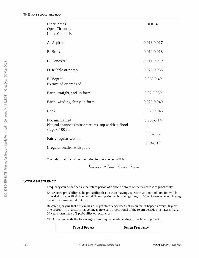
DO N
OT
DIST
RIBU
TE -
Prin
ting
for S
tude
nt U
se is
Per
mitt
ed
Co
mpa
ny: V
irgin
ia D
OT
C
lass
Dat
e: 2
0-M
ay-2
013
THE RATIONAL METHOD
12-6 © 2011 Bentley Systems, Incorporated VDOT GEOPAK Drainage
Liner Plates 0.013- Open Channels Lined Channels:
A. Asphalt
B. Brick
C. Concrete
D. Rubble or riprap
E. Vegetal
0.013-0.017
0.012-0.018
0.011-0.020
0.020-0.035
0.030-0.40 Excavated or dredged
Earth, straight, and uniform
Earth, winding, fairly uniform
Rock
Not maintained
0.02-0.030
0.025-0.040
0.030-0.045
0.050-0.14 Natural channels (minor streams, top width at flood stage < 100 ft.
Fairly regular section
Irregular section with pools
0.03-0.07
0.04-0.10
Then, the total time of concentration for a watershed will be:
channelshallowsheetionconcentrat TTTT ++=
STORM FREQUENCY Frequency can be defined as the return period of a specific storm or their exceedance probability.
Exceedance probability is the probability that an event having a specific volume and duration will be exceeded in a specified time period. Return period is the average length of time between events having the same volume and duration.
Be careful, saying that a storm has a 50 year frequency does not mean that it happens every 50 years. The probability of a storm happening is inversely proportional of the return period. This means that a 50 year storm has a 2% probability of recurrence.
VDOT recommends the following design frequencies depending of the type of project:
Type of Project Design Frequency
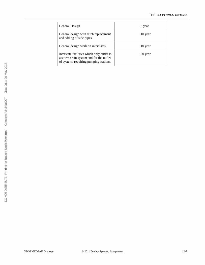
DO N
OT
DIST
RIBU
TE -
Prin
ting
for S
tude
nt U
se is
Per
mitt
ed
Co
mpa
ny: V
irgin
ia D
OT
C
lass
Dat
e: 2
0-M
ay-2
013
THE RATIONAL METHOD
VDOT GEOPAK Drainage © 2011 Bentley Systems, Incorporated 12-7
General Design 3 year
General design with ditch replacement and adding of side pipes.
10 year
General design work on interstates 10 year
Interstate facilities which only outlet is a storm drain system and for the outlet of systems requiring pumping stations.
50 year
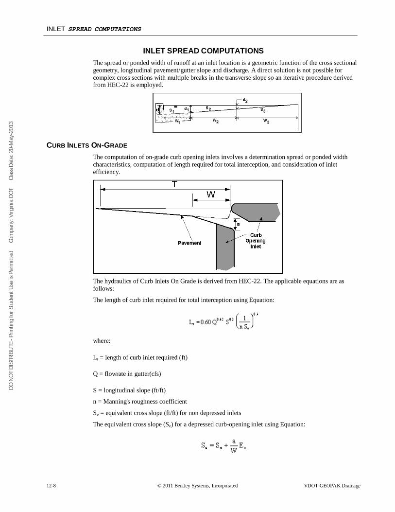
DO N
OT
DIST
RIBU
TE -
Prin
ting
for S
tude
nt U
se is
Per
mitt
ed
Co
mpa
ny: V
irgin
ia D
OT
C
lass
Dat
e: 2
0-M
ay-2
013
INLET SPREAD COMPUTATIONS
12-8 © 2011 Bentley Systems, Incorporated VDOT GEOPAK Drainage
INLET SPREAD COMPUTATIONS The spread or ponded width of runoff at an inlet location is a geometric function of the cross sectional geometry, longitudinal pavement/gutter slope and discharge. A direct solution is not possible for complex cross sections with multiple breaks in the transverse slope so an iterative procedure derived from HEC-22 is employed.
CURB INLETS ON-GRADE The computation of on-grade curb opening inlets involves a determination spread or ponded width characteristics, computation of length required for total interception, and consideration of inlet efficiency.
The hydraulics of Curb Inlets On Grade is derived from HEC-22. The applicable equations are as follows:
The length of curb inlet required for total interception using Equation:
where:
Lr = length of curb inlet required (ft)
Q = flowrate in gutter(cfs)
S = longitudinal slope (ft/ft)
n = Manning's roughness coefficient
Se = equivalent cross slope (ft/ft) for non depressed inlets
The equivalent cross slope (Se) for a depressed curb-opening inlet using Equation:
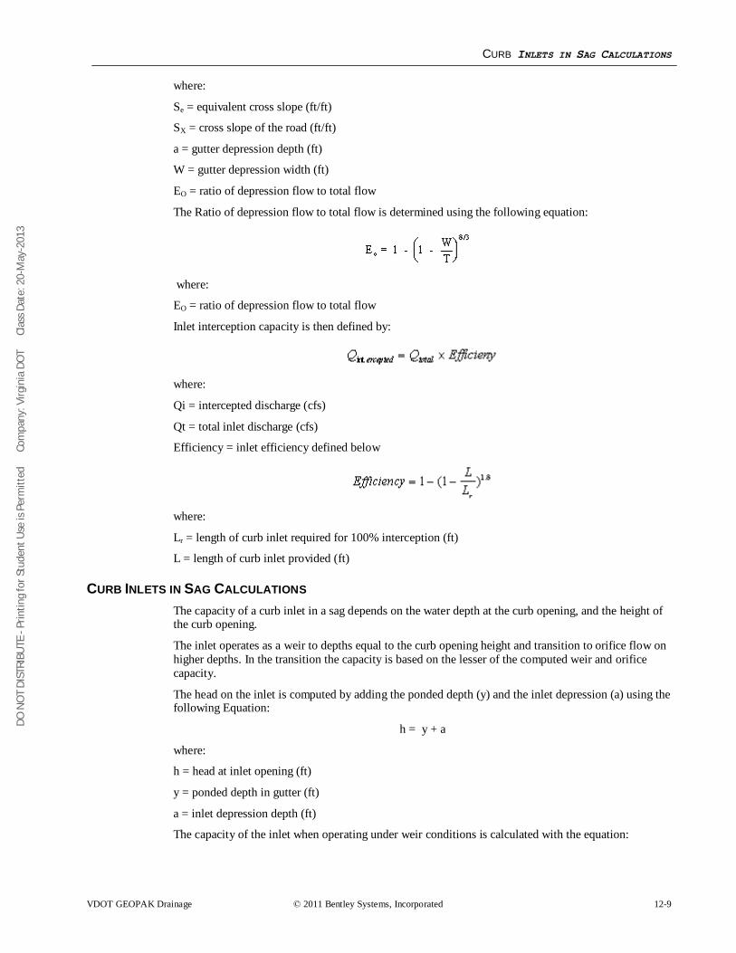
DO N
OT
DIST
RIBU
TE -
Prin
ting
for S
tude
nt U
se is
Per
mitt
ed
Co
mpa
ny: V
irgin
ia D
OT
C
lass
Dat
e: 2
0-M
ay-2
013
CURB INLETS IN SAG CALCULATIONS
VDOT GEOPAK Drainage © 2011 Bentley Systems, Incorporated 12-9
where:
Se = equivalent cross slope (ft/ft)
SX = cross slope of the road (ft/ft)
a = gutter depression depth (ft)
W = gutter depression width (ft)
EO = ratio of depression flow to total flow
The Ratio of depression flow to total flow is determined using the following equation:
where:
EO = ratio of depression flow to total flow
Inlet interception capacity is then defined by:
where:
Qi = intercepted discharge (cfs)
Qt = total inlet discharge (cfs)
Efficiency = inlet efficiency defined below
where:
Lr = length of curb inlet required for 100% interception (ft)
L = length of curb inlet provided (ft)
CURB INLETS IN SAG CALCULATIONS The capacity of a curb inlet in a sag depends on the water depth at the curb opening, and the height of the curb opening.
The inlet operates as a weir to depths equal to the curb opening height and transition to orifice flow on higher depths. In the transition the capacity is based on the lesser of the computed weir and orifice capacity.
The head on the inlet is computed by adding the ponded depth (y) and the inlet depression (a) using the following Equation:
h = y + a
where:
h = head at inlet opening (ft)
y = ponded depth in gutter (ft)
a = inlet depression depth (ft)
The capacity of the inlet when operating under weir conditions is calculated with the equation:
DO N
OT
DIST
RIBU
TE -
Prin
ting
for S
tude
nt U
se is
Per
mitt
ed
Co
mpa
ny: V
irgin
ia D
OT
C
lass
Dat
e: 2
0-M
ay-2
013
GRATE INLETS ON-GRADE CALCULATIONS
12-10 © 2011 Bentley Systems, Incorporated VDOT GEOPAK Drainage
where:
Q = total flow reaching inlet (cfs)
CW = weir coefficient = 2.3
h = head at inlet opening (ft)
L = length of curb inlet opening (ft)
W = lateral width of inlet depression (ft)
The equation for interception capacity of a curb opening operating as an orifice follows:
where:
Q = total flow reaching inlet (ft3/s)
Co = orifice coefficient = 0.67
h = depth of opening (ft)
L = length of curb opening inlet (ft)
g = acceleration due to gravity = 32.2 ft/s2
do = effective head at the centroid of the orifice (ft)
GRATE INLETS ON-GRADE CALCULATIONS The capacity of a grate inlet on-grade depends on its geometry and the cross slope, longitudinal slope, total gutter flow, depth of flow, and pavement roughness. The design of a grate inlet on-grade involves an analysis of given grate dimensions to estimate the interception rate. The difference between the estimated interception rate and the total approach discharge equals the bypass rate. The following procedure is applicable to grate inlets on-grade:
The Ratio of discharge over the grate (Frontal Flow) to flow to total flow is determined using the following equation:
where:
EO = ratio of flow over the grate to total flow
The ratio of frontal flow intercepted to total frontal flow:
where:
Rf = ratio of frontal flow intercepted to total frontal flow
V = approach velocity of flow in gutter (ft/s)
Vo = minimum velocity that will cause splash over grate (ft/s)
The splash over velocity is of the form of
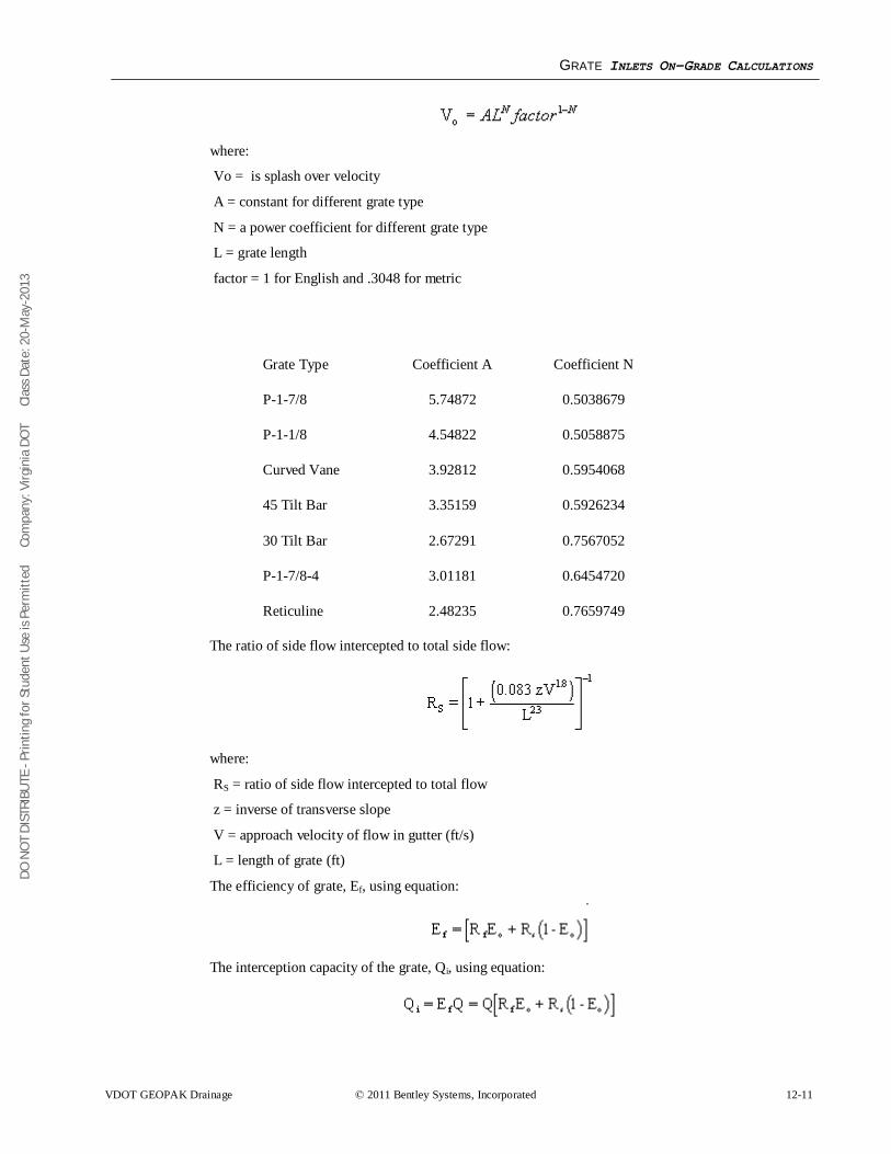
DO N
OT
DIST
RIBU
TE -
Prin
ting
for S
tude
nt U
se is
Per
mitt
ed
Co
mpa
ny: V
irgin
ia D
OT
C
lass
Dat
e: 2
0-M
ay-2
013
GRATE INLETS ON-GRADE CALCULATIONS
VDOT GEOPAK Drainage © 2011 Bentley Systems, Incorporated 12-11
where:
Vo = is splash over velocity
A = constant for different grate type
N = a power coefficient for different grate type
L = grate length
factor = 1 for English and .3048 for metric
Grate Type Coefficient A Coefficient N
P-1-7/8 5.74872 0.5038679
P-1-1/8 4.54822 0.5058875
Curved Vane 3.92812 0.5954068
45 Tilt Bar 3.35159 0.5926234
30 Tilt Bar 2.67291 0.7567052
P-1-7/8-4 3.01181 0.6454720
Reticuline 2.48235 0.7659749
The ratio of side flow intercepted to total side flow:
where:
RS = ratio of side flow intercepted to total flow
z = inverse of transverse slope
V = approach velocity of flow in gutter (ft/s)
L = length of grate (ft)
The efficiency of grate, Ef, using equation:
The interception capacity of the grate, Qi, using equation:
DO N
OT
DIST
RIBU
TE -
Prin
ting
for S
tude
nt U
se is
Per
mitt
ed
Co
mpa
ny: V
irgin
ia D
OT
C
lass
Dat
e: 2
0-M
ay-2
013
GRATE INLETS IN SAG CALCULATIONS
12-12 © 2011 Bentley Systems, Incorporated VDOT GEOPAK Drainage
The bypass flow rate:
GRATE INLETS IN SAG CALCULATIONS A grate inlet in sag configuration operates in weir flow at low ponding depths. The transition to orifice flow begins as the ponded depth increases. The procedure for calculating the inlet capacity is as follows:
The capacity of a grate inlet operating as a weir is determined with the following equation:
where:
Qw = weir capacity of grate (cfs)
Cw = weir coefficient = 3.087
P = perimeter of the grate (ft)
h = allowable head on grate (ft)
PR = perimeter reduction factor to account for clogging
Under orifice conditions, the grate area controls the capacity. The capacity of a grate inlet operating under orifice flow is computed equation:
where:
Qo = orifice capacity of grate (cfs)
Co = orifice flow coefficient = 0.67
A = clear opening area (ft2) of the grate (the total area available for flow)
g = acceleration due to gravity (32.2 ft/s2)
h = allowable head on grate (ft)
AR = area reduction factor to account for clogging
The capacity of a grated inlet in a sag is based on the minimum flow calculated from weir and orifice conditions. The figure below demonstrates the relationship between weir and orifice flow. If Qo is greater than Qw (to the left of the intersection in the figure), then the capacity would be that calculated with the weir equation. If, however, Qo is less than Qw (to the right of the intersection), then the capacity as determined with the orifice equation would be used.
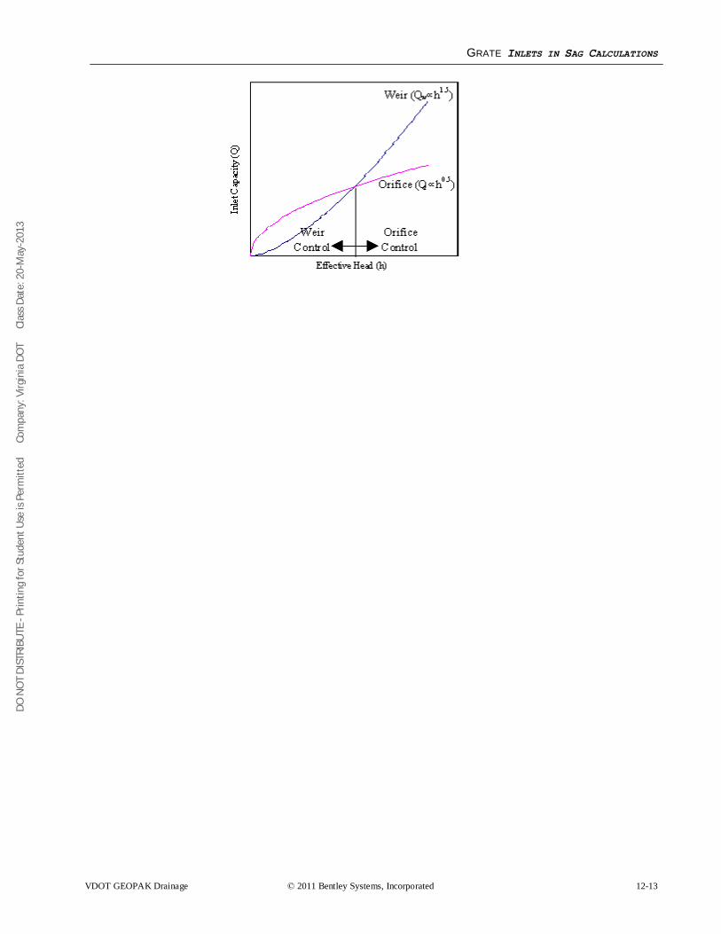
DO N
OT
DIST
RIBU
TE -
Prin
ting
for S
tude
nt U
se is
Per
mitt
ed
Co
mpa
ny: V
irgin
ia D
OT
C
lass
Dat
e: 2
0-M
ay-2
013
GRATE INLETS IN SAG CALCULATIONS
VDOT GEOPAK Drainage © 2011 Bentley Systems, Incorporated 12-13
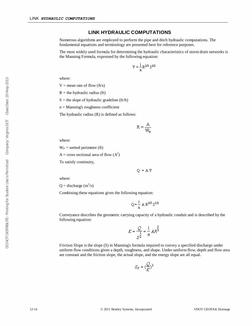
DO N
OT
DIST
RIBU
TE -
Prin
ting
for S
tude
nt U
se is
Per
mitt
ed
Co
mpa
ny: V
irgin
ia D
OT
C
lass
Dat
e: 2
0-M
ay-2
013
LINK HYDRAULIC COMPUTATIONS
12-14 © 2011 Bentley Systems, Incorporated VDOT GEOPAK Drainage
LINK HYDRAULIC COMPUTATIONS Numerous algorithms are employed to perform the pipe and ditch hydraulic computations. The fundamental equations and terminology are presented here for reference purposes.
The most widely used formula for determining the hydraulic characteristics of storm drain networks is the Manning Formula, expressed by the following equation:
where:
V = mean rate of flow (ft/s)
R = the hydraulic radius (ft)
S = the slope of hydraulic gradeline (ft/ft)
n = Manning's roughness coefficient
The hydraulic radius (R) is defined as follows:
where:
WP = wetted perimeter (ft)
A = cross sectional area of flow (A2)
To satisfy continuity,
where:
Q = discharge (m3/s)
Combining these equations gives the following equation:
Conveyance describes the geometric carrying capacity of a hydraulic conduit and is described by the following equation:
Friction Slope is the slope (S) in Manning's formula required to convey a specified discharge under uniform flow conditions given a depth, roughness, and shape. Under uniform flow, depth and flow area are constant and the friction slope, the actual slope, and the energy slope are all equal.
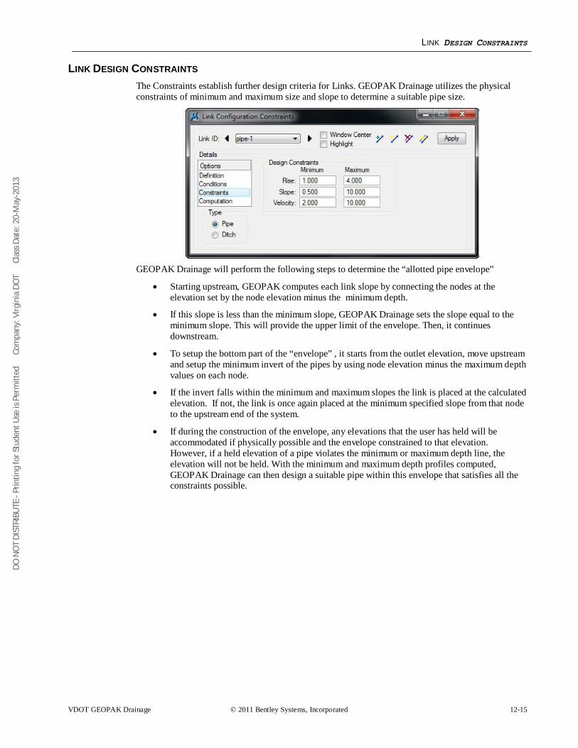
DO N
OT
DIST
RIBU
TE -
Prin
ting
for S
tude
nt U
se is
Per
mitt
ed
Co
mpa
ny: V
irgin
ia D
OT
C
lass
Dat
e: 2
0-M
ay-2
013
LINK DESIGN CONSTRAINTS
VDOT GEOPAK Drainage © 2011 Bentley Systems, Incorporated 12-15
LINK DESIGN CONSTRAINTS The Constraints establish further design criteria for Links. GEOPAK Drainage utilizes the physical constraints of minimum and maximum size and slope to determine a suitable pipe size.
GEOPAK Drainage will perform the following steps to determine the “allotted pipe envelope”
• Starting upstream, GEOPAK computes each link slope by connecting the nodes at the elevation set by the node elevation minus the minimum depth.
• If this slope is less than the minimum slope, GEOPAK Drainage sets the slope equal to the minimum slope. This will provide the upper limit of the envelope. Then, it continues downstream.
• To setup the bottom part of the “envelope” , it starts from the outlet elevation, move upstream and setup the minimum invert of the pipes by using node elevation minus the maximum depth values on each node.
• If the invert falls within the minimum and maximum slopes the link is placed at the calculated elevation. If not, the link is once again placed at the minimum specified slope from that node to the upstream end of the system.
• If during the construction of the envelope, any elevations that the user has held will be accommodated if physically possible and the envelope constrained to that elevation. However, if a held elevation of a pipe violates the minimum or maximum depth line, the elevation will not be held. With the minimum and maximum depth profiles computed, GEOPAK Drainage can then design a suitable pipe within this envelope that satisfies all the constraints possible.
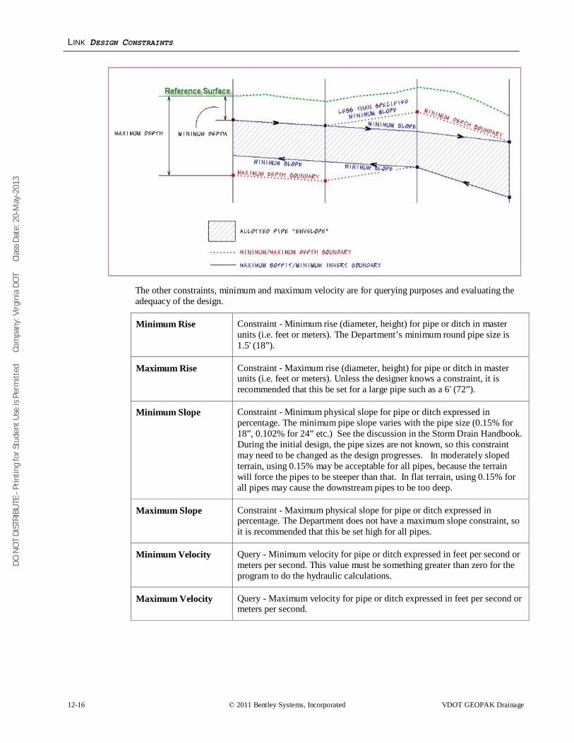
DO N
OT
DIST
RIBU
TE -
Prin
ting
for S
tude
nt U
se is
Per
mitt
ed
Co
mpa
ny: V
irgin
ia D
OT
C
lass
Dat
e: 2
0-M
ay-2
013
LINK DESIGN CONSTRAINTS
12-16 © 2011 Bentley Systems, Incorporated VDOT GEOPAK Drainage
The other constraints, minimum and maximum velocity are for querying purposes and evaluating the adequacy of the design.
Minimum Rise Constraint - Minimum rise (diameter, height) for pipe or ditch in master units (i.e. feet or meters). The Department’s minimum round pipe size is 1.5' (18”).
Maximum Rise Constraint - Maximum rise (diameter, height) for pipe or ditch in master units (i.e. feet or meters). Unless the designer knows a constraint, it is recommended that this be set for a large pipe such as a 6' (72”).
Minimum Slope Constraint - Minimum physical slope for pipe or ditch expressed in percentage. The minimum pipe slope varies with the pipe size (0.15% for 18”, 0.102% for 24” etc.) See the discussion in the Storm Drain Handbook. During the initial design, the pipe sizes are not known, so this constraint may need to be changed as the design progresses. In moderately sloped terrain, using 0.15% may be acceptable for all pipes, because the terrain will force the pipes to be steeper than that. In flat terrain, using 0.15% for all pipes may cause the downstream pipes to be too deep.
Maximum Slope Constraint - Maximum physical slope for pipe or ditch expressed in percentage. The Department does not have a maximum slope constraint, so it is recommended that this be set high for all pipes.
Minimum Velocity Query - Minimum velocity for pipe or ditch expressed in feet per second or meters per second. This value must be something greater than zero for the program to do the hydraulic calculations.
Maximum Velocity Query - Maximum velocity for pipe or ditch expressed in feet per second or meters per second.
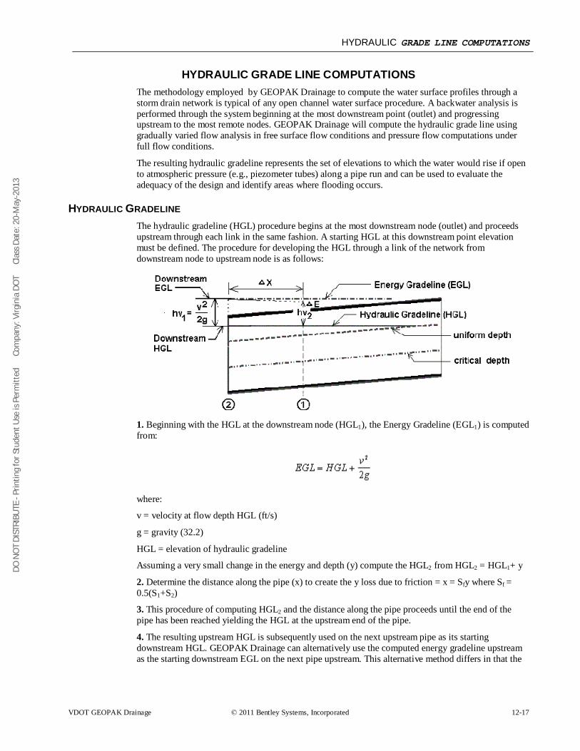
DO N
OT
DIST
RIBU
TE -
Prin
ting
for S
tude
nt U
se is
Per
mitt
ed
Co
mpa
ny: V
irgin
ia D
OT
C
lass
Dat
e: 2
0-M
ay-2
013
HYDRAULIC GRADE LINE COMPUTATIONS
VDOT GEOPAK Drainage © 2011 Bentley Systems, Incorporated 12-17
HYDRAULIC GRADE LINE COMPUTATIONS The methodology employed by GEOPAK Drainage to compute the water surface profiles through a storm drain network is typical of any open channel water surface procedure. A backwater analysis is performed through the system beginning at the most downstream point (outlet) and progressing upstream to the most remote nodes. GEOPAK Drainage will compute the hydraulic grade line using gradually varied flow analysis in free surface flow conditions and pressure flow computations under full flow conditions.
The resulting hydraulic gradeline represents the set of elevations to which the water would rise if open to atmospheric pressure (e.g., piezometer tubes) along a pipe run and can be used to evaluate the adequacy of the design and identify areas where flooding occurs.
HYDRAULIC GRADELINE The hydraulic gradeline (HGL) procedure begins at the most downstream node (outlet) and proceeds upstream through each link in the same fashion. A starting HGL at this downstream point elevation must be defined. The procedure for developing the HGL through a link of the network from downstream node to upstream node is as follows:
1. Beginning with the HGL at the downstream node (HGL1), the Energy Gradeline (EGL1) is computed from:
where:
v = velocity at flow depth HGL (ft/s)
g = gravity (32.2)
HGL = elevation of hydraulic gradeline
Assuming a very small change in the energy and depth (y) compute the HGL2 from HGL2 = HGL1+ y
2. Determine the distance along the pipe (x) to create the y loss due to friction = x = Sfy where Sf = 0.5(S1+S2)
3. This procedure of computing HGL2 and the distance along the pipe proceeds until the end of the pipe has been reached yielding the HGL at the upstream end of the pipe.
4. The resulting upstream HGL is subsequently used on the next upstream pipe as its starting downstream HGL. GEOPAK Drainage can alternatively use the computed energy gradeline upstream as the starting downstream EGL on the next pipe upstream. This alternative method differs in that the
DO N
OT
DIST
RIBU
TE -
Prin
ting
for S
tude
nt U
se is
Per
mitt
ed
Co
mpa
ny: V
irgin
ia D
OT
C
lass
Dat
e: 2
0-M
ay-2
013
SPECIAL CONSIDERATIONS
12-18 © 2011 Bentley Systems, Incorporated VDOT GEOPAK Drainage
EGL's upstream and downstream at a node are equal rather than the conventional assumption that the HGL's are equal.
5. If junction losses are desired they computed prior to progressing upstream and added to the hydraulic gradeline.
SPECIAL CONSIDERATIONS • If the starting HGL is less than critical depth then critical depth will be assumed.
• If the HGL converges to equal the uniform depth the computations proceed to the upstream end at uniform depth
• Once the HGL reaches the soffit of the pipe full flow conditions begin.
• Hydraulically steep pipes where uniform depth is less than the critical depth are checked with a backwater profile to verify if the resulting upstream HGL drowns out critical depth at the upstream end. If it does than the backwater profile is accepted. If the backwater curve does not exceed the critical depth, then a forewater profile is generated for this supercritical condition. A forewater profile uses the same procedure as above but progresses from the upstream end towards the downstream end. It begins at critical depth at the upstream end and converges towards uniform depth as the calculations proceed downstream.
• Hydraulic jumps may occur when mixing supercritical and subcritical water surface profiles. GEOPAK Drainage does not compute the exact location of a jump but will check if downstream subcritical depths have sufficient energy to force a supercritical profile to its conjugate depth thereby satisfying the conditions required for a jump to occur. Message will be appear indicating the existence of a jump.
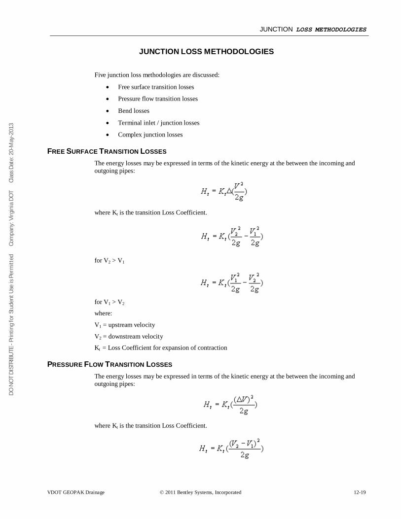
DO N
OT
DIST
RIBU
TE -
Prin
ting
for S
tude
nt U
se is
Per
mitt
ed
Co
mpa
ny: V
irgin
ia D
OT
C
lass
Dat
e: 2
0-M
ay-2
013
JUNCTION LOSS METHODOLOGIES
VDOT GEOPAK Drainage © 2011 Bentley Systems, Incorporated 12-19
JUNCTION LOSS METHODOLOGIES
Five junction loss methodologies are discussed:
• Free surface transition losses
• Pressure flow transition losses
• Bend losses
• Terminal inlet / junction losses
• Complex junction losses
FREE SURFACE TRANSITION LOSSES The energy losses may be expressed in terms of the kinetic energy at the between the incoming and outgoing pipes:
where Kt is the transition Loss Coefficient.
for V2 > V1
for V1 > V2
where:
V1 = upstream velocity
V2 = downstream velocity
Kt = Loss Coefficient for expansion of contraction
PRESSURE FLOW TRANSITION LOSSES The energy losses may be expressed in terms of the kinetic energy at the between the incoming and outgoing pipes:
where Kt is the transition Loss Coefficient.
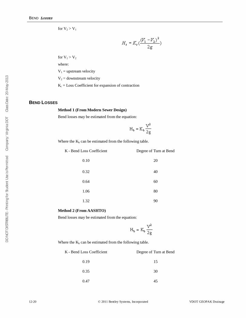
DO N
OT
DIST
RIBU
TE -
Prin
ting
for S
tude
nt U
se is
Per
mitt
ed
Co
mpa
ny: V
irgin
ia D
OT
C
lass
Dat
e: 2
0-M
ay-2
013
BEND LOSSES
12-20 © 2011 Bentley Systems, Incorporated VDOT GEOPAK Drainage
for V2 > V1
for V1 > V2
where:
V1 = upstream velocity
V2 = downstream velocity
Kt = Loss Coefficient for expansion of contraction
BEND LOSSES Method 1 (From Modern Sewer Design)
Bend losses may be estimated from the equation:
Where the Kb can be estimated from the following table.
K - Bend Loss Coefficient Degree of Turn at Bend
0.10 20
0.32 40
0.64 60
1.06 80
1.32 90
Method 2 (From AASHTO)
Bend losses may be estimated from the equation:
Where the Kb can be estimated from the following table.
K - Bend Loss Coefficient Degree of Turn at Bend
0.19 15
0.35 30
0.47 45
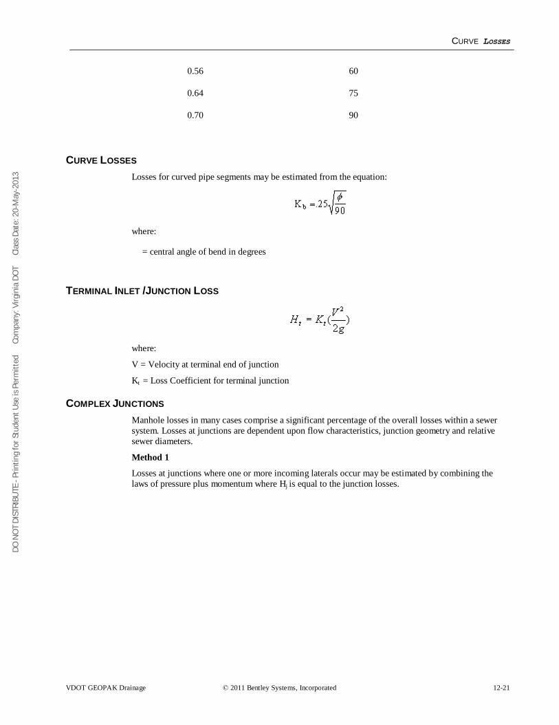
DO N
OT
DIST
RIBU
TE -
Prin
ting
for S
tude
nt U
se is
Per
mitt
ed
Co
mpa
ny: V
irgin
ia D
OT
C
lass
Dat
e: 2
0-M
ay-2
013
CURVE LOSSES
VDOT GEOPAK Drainage © 2011 Bentley Systems, Incorporated 12-21
0.56 60
0.64 75
0.70 90
CURVE LOSSES Losses for curved pipe segments may be estimated from the equation:
where:
= central angle of bend in degrees
TERMINAL INLET /JUNCTION LOSS
where:
V = Velocity at terminal end of junction
Kt = Loss Coefficient for terminal junction
COMPLEX JUNCTIONS Manhole losses in many cases comprise a significant percentage of the overall losses within a sewer system. Losses at junctions are dependent upon flow characteristics, junction geometry and relative sewer diameters.
Method 1
Losses at junctions where one or more incoming laterals occur may be estimated by combining the laws of pressure plus momentum where Hj is equal to the junction losses.
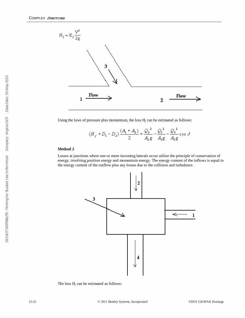
DO N
OT
DIST
RIBU
TE -
Prin
ting
for S
tude
nt U
se is
Per
mitt
ed
Co
mpa
ny: V
irgin
ia D
OT
C
lass
Dat
e: 2
0-M
ay-2
013
COMPLEX JUNCTIONS
12-22 © 2011 Bentley Systems, Incorporated VDOT GEOPAK Drainage
Using the laws of pressure plus momentum, the loss Hj can be estimated as follows:
Method 2
Losses at junctions where one or more incoming laterals occur utilize the principle of conservation of energy, involving position energy and momentum energy. The energy content of the inflows is equal to the energy content of the outflow plus any losses due to the collision and turbulence.
The loss Hj can be estimated as follows:
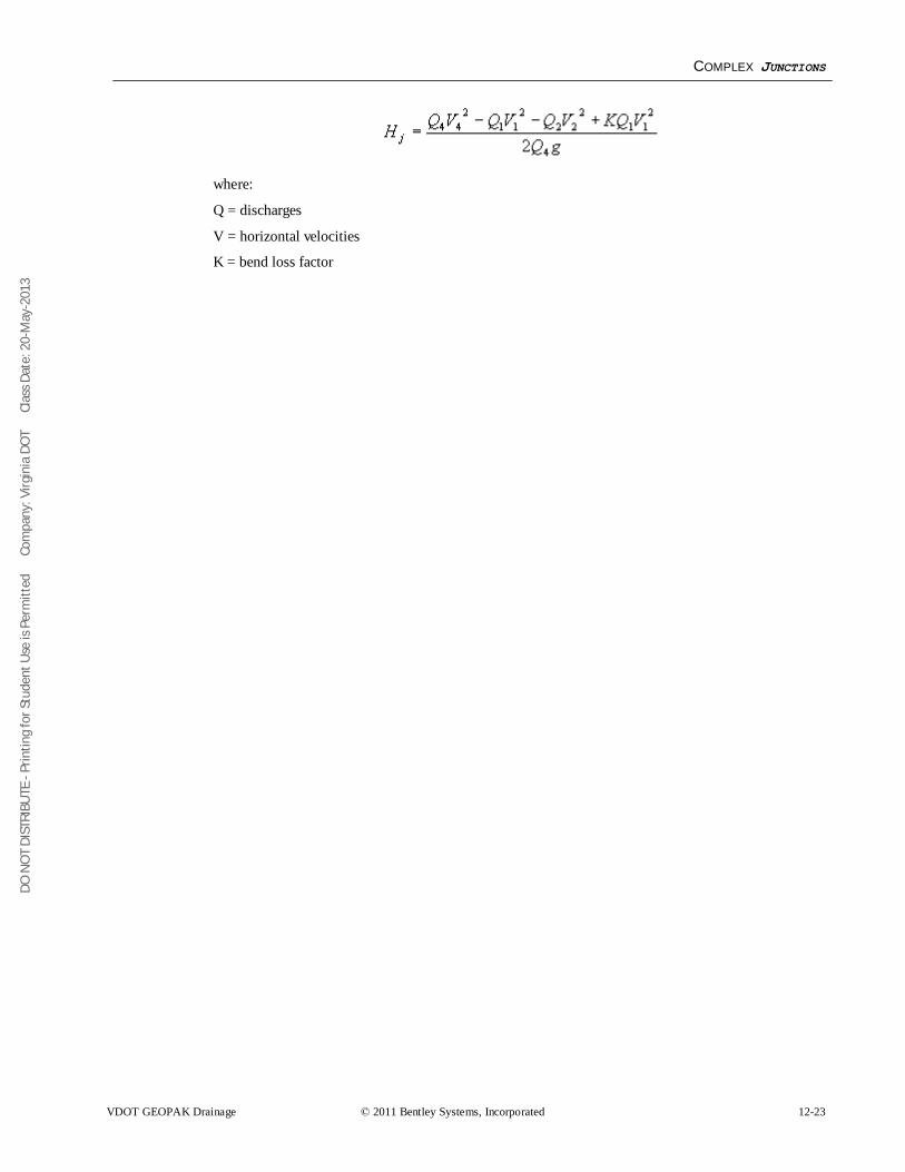
DO N
OT
DIST
RIBU
TE -
Prin
ting
for S
tude
nt U
se is
Per
mitt
ed
Co
mpa
ny: V
irgin
ia D
OT
C
lass
Dat
e: 2
0-M
ay-2
013
COMPLEX JUNCTIONS
VDOT GEOPAK Drainage © 2011 Bentley Systems, Incorporated 12-23
where:
Q = discharges
V = horizontal velocities
K = bend loss factor
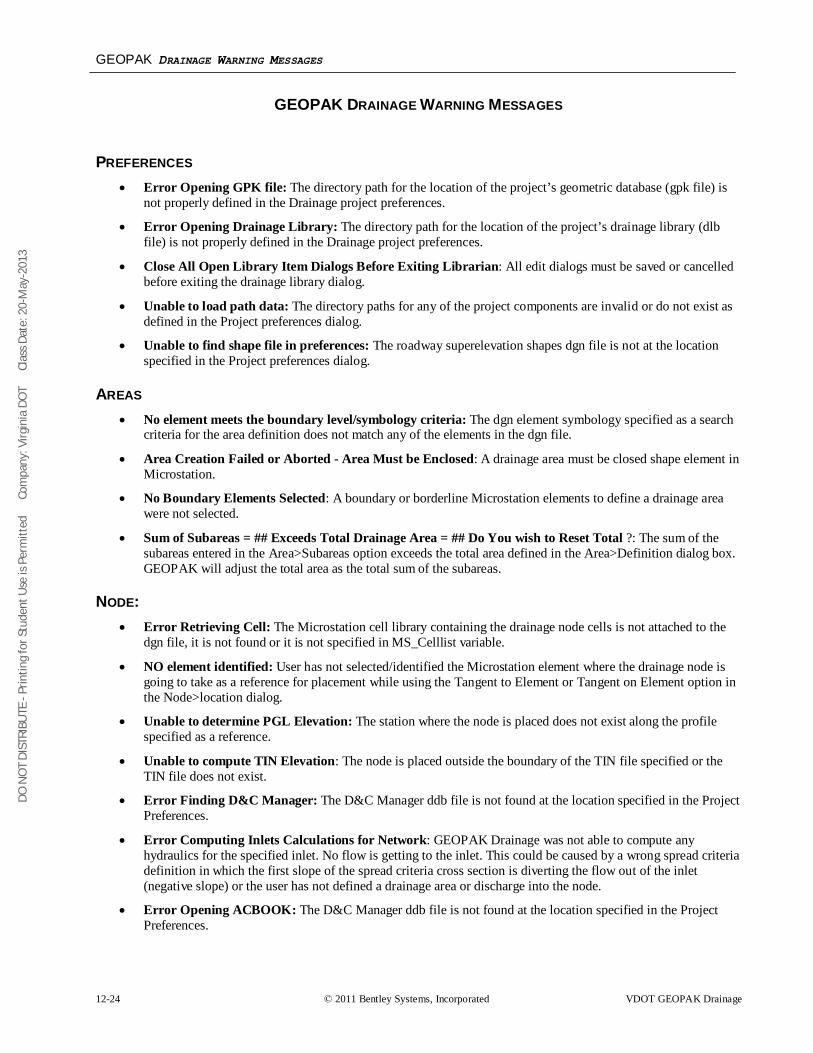
DO N
OT
DIST
RIBU
TE -
Prin
ting
for S
tude
nt U
se is
Per
mitt
ed
Co
mpa
ny: V
irgin
ia D
OT
C
lass
Dat
e: 2
0-M
ay-2
013
GEOPAK DRAINAGE WARNING MESSAGES
12-24 © 2011 Bentley Systems, Incorporated VDOT GEOPAK Drainage
GEOPAK DRAINAGE WARNING MESSAGES
PREFERENCES • Error Opening GPK file: The directory path for the location of the project’s geometric database (gpk file) is
not properly defined in the Drainage project preferences.
• Error Opening Drainage Library: The directory path for the location of the project’s drainage library (dlb file) is not properly defined in the Drainage project preferences.
• Close All Open Library Item Dialogs Before Exiting Librarian: All edit dialogs must be saved or cancelled before exiting the drainage library dialog.
• Unable to load path data: The directory paths for any of the project components are invalid or do not exist as defined in the Project preferences dialog.
• Unable to find shape file in preferences: The roadway superelevation shapes dgn file is not at the location specified in the Project preferences dialog.
AREAS • No element meets the boundary level/symbology criteria: The dgn element symbology specified as a search
criteria for the area definition does not match any of the elements in the dgn file.
• Area Creation Failed or Aborted - Area Must be Enclosed: A drainage area must be closed shape element in Microstation.
• No Boundary Elements Selected: A boundary or borderline Microstation elements to define a drainage area were not selected.
• Sum of Subareas = ## Exceeds Total Drainage Area = ## Do You wish to Reset Total ?: The sum of the subareas entered in the Area>Subareas option exceeds the total area defined in the Area>Definition dialog box. GEOPAK will adjust the total area as the total sum of the subareas.
NODE: • Error Retrieving Cell: The Microstation cell library containing the drainage node cells is not attached to the
dgn file, it is not found or it is not specified in MS_Celllist variable.
• NO element identified: User has not selected/identified the Microstation element where the drainage node is going to take as a reference for placement while using the Tangent to Element or Tangent on Element option in the Node>location dialog.
• Unable to determine PGL Elevation: The station where the node is placed does not exist along the profile specified as a reference.
• Unable to compute TIN Elevation: The node is placed outside the boundary of the TIN file specified or the TIN file does not exist.
• Error Finding D&C Manager: The D&C Manager ddb file is not found at the location specified in the Project Preferences.
• Error Computing Inlets Calculations for Network: GEOPAK Drainage was not able to compute any hydraulics for the specified inlet. No flow is getting to the inlet. This could be caused by a wrong spread criteria definition in which the first slope of the spread criteria cross section is diverting the flow out of the inlet (negative slope) or the user has not defined a drainage area or discharge into the node.
• Error Opening ACBOOK: The D&C Manager ddb file is not found at the location specified in the Project Preferences.
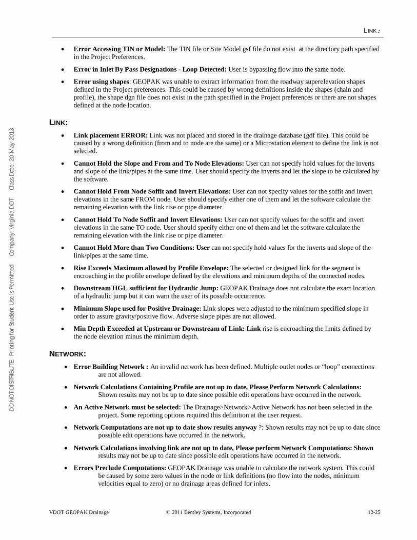
DO N
OT
DIST
RIBU
TE -
Prin
ting
for S
tude
nt U
se is
Per
mitt
ed
Co
mpa
ny: V
irgin
ia D
OT
C
lass
Dat
e: 2
0-M
ay-2
013
LINK:
VDOT GEOPAK Drainage © 2011 Bentley Systems, Incorporated 12-25
• Error Accessing TIN or Model: The TIN file or Site Model gsf file do not exist at the directory path specified in the Project Preferences.
• Error in Inlet By Pass Designations - Loop Detected: User is bypassing flow into the same node.
• Error using shapes: GEOPAK was unable to extract information from the roadway superelevation shapes defined in the Project preferences. This could be caused by wrong definitions inside the shapes (chain and profile), the shape dgn file does not exist in the path specified in the Project preferences or there are not shapes defined at the node location.
LINK: • Link placement ERROR: Link was not placed and stored in the drainage database (gdf file). This could be
caused by a wrong definition (from and to node are the same) or a Microstation element to define the link is not selected.
• Cannot Hold the Slope and From and To Node Elevations: User can not specify hold values for the inverts and slope of the link/pipes at the same time. User should specify the inverts and let the slope to be calculated by the software.
• Cannot Hold From Node Soffit and Invert Elevations: User can not specify values for the soffit and invert elevations in the same FROM node. User should specify either one of them and let the software calculate the remaining elevation with the link rise or pipe diameter.
• Cannot Hold To Node Soffit and Invert Elevations: User can not specify values for the soffit and invert elevations in the same TO node. User should specify either one of them and let the software calculate the remaining elevation with the link rise or pipe diameter.
• Cannot Hold More than Two Conditions: User can not specify hold values for the inverts and slope of the link/pipes at the same time.
• Rise Exceeds Maximum allowed by Profile Envelope: The selected or designed link for the segment is encroaching in the profile envelope defined by the elevations and minimum depths of the connected nodes.
• Downstream HGL sufficient for Hydraulic Jump: GEOPAK Drainage does not calculate the exact location of a hydraulic jump but it can warn the user of its possible occurrence.
• Minimum Slope used for Positive Drainage: Link slopes were adjusted to the minimum specified slope in order to assure gravity/positive flow. Adverse slope pipes are not allowed.
• Min Depth Exceeded at Upstream or Downstream of Link: Link rise is encroaching the limits defined by the node elevation minus the minimum depth.
NETWORK: • Error Building Network : An invalid network has been defined. Multiple outlet nodes or “loop” connections
are not allowed.
• Network Calculations Containing Profile are not up to date, Please Perform Network Calculations: Shown results may not be up to date since possible edit operations have occurred in the network.
• An Active Network must be selected: The Drainage>Network>Active Network has not been selected in the project. Some reporting options required this definition at the user request.
• Network Computations are not up to date show results anyway ?: Shown results may not be up to date since possible edit operations have occurred in the network.
• Network Calculations involving link are not up to date, Please perform Network Computations: Shown results may not be up to date since possible edit operations have occurred in the network.
• Errors Preclude Computations: GEOPAK Drainage was unable to calculate the network system. This could be caused by some zero values in the node or link definitions (no flow into the nodes, minimum velocities equal to zero) or no drainage areas defined for inlets.
DO N
OT
DIST
RIBU
TE -
Prin
ting
for S
tude
nt U
se is
Per
mitt
ed
Co
mpa
ny: V
irgin
ia D
OT
C
lass
Dat
e: 2
0-M
ay-2
013
PROFILES
12-26 © 2011 Bentley Systems, Incorporated VDOT GEOPAK Drainage
• HGL Blowout at upstream end: The hydraulic grade line is encroaching the limits defined by the node elevation minus the minimum freeboard value (defined in the Project Preferences).
• Commingling Runoff Methods not supported: GEOPAK Drainage can compute a network either using the Rational or SCS method for the drainage areas definitions.
• Error Building Network - More than One Outlet found: An invalid network has been defined. Multiple outlet nodes are not supported.
• Error Building Network - Loop or Multiple Downstream Links: An invalid network has been defined. Loop or closed circuits connections are not supported.
• Error Building Network - More than five Incoming Links for Node: GEOPAK Drainage does not allow more that five link/pipes connections in a node.
PROFILES • Unsuccessfully projecting to chain __ from link __: The chain extends/limits does not include the
link location.
• Error Accessing TIN or Model: The TIN does not exist at the directory path specified in the Project Preferences.
• Drainage Profile __ contains Node __: The Drainage Profile dialog must be closed to edit this node: The Drainage Profile dialog must be closed before editing a node that is part of the active profile.
• Drainage Profile __ contains Link __:The Drainage Profile dialog must be closed to edit this link: The Drainage Profile dialog must be closed before editing a link that is part of the active profile.
NAVIGATOR • No Queries Available for Selected Type: There are no query options for the drainage element type
selected.
• No Elements Meeting Query were found: An specific query has returned no results.
ROUTING • Unable to load computation file: The ASCII file specified to store the computations was not
previously created while in Append mode.
DO N
OT
DIST
RIBU
TE -
Prin
ting
for S
tude
nt U
se is
Per
mitt
ed
Co
mpa
ny: V
irgin
ia D
OT
C
lass
Dat
e: 2
0-M
ay-2
013
GEOPAK REPORT BUILDER VARIABLES
VDOT GEOPAK Drainage © 2011 Bentley Systems, Incorporated 12-27
GEOPAK REPORT BUILDER VARIABLES
AREA Area-ID: Drainage area name/identification stored in the drainage database (gdf file)
Area – Description: Drainage area user provided description.
Area - Time of Concentration: User provided or calculated time of concentration.
Area - Tc Used: Time of concentration used in the calculation for the drainage area discharge.
Area – Discharge: Computed discharge for the drainage area.
Area – Intensity: Intensity rainfall used as computed from the time of concentration and rainfall library.
Area - Composite C Value: Calculated composite C coefficient for the Rational method.
Area - Composite Area: Calculated composite area value for the Rational method.
Area - Total Subarea C Value: Calculated composite C value for only the delineated subareas.
Area - Total Subarea: Sum of the delineated subareas only.
Area - Remainder C Value: C coefficient of the area not included into the delineated subareas.
Area - Remainder Area: Calculated value equal to Total Drainage Area minus the Total Subareas.
Area - Subarea 1…20 Area: Area value of the 1..20 delineated subarea.
Area - Subarea 1…20 C Value: C coefficient of the 1..20 delineated subarea.
Area - Subarea 1…20 Description: Description of the 1..20 delineated subarea.
NODE Node-ID: Drainage node name/identification stored in the drainage database (gdf file)
Node – Description: Drainage node user provided description.
Node – Type: Node type as defined in the drainage library. E.g. curb, grate, junction, other, curb-grate, headwall.
Node - Library Item Name: Node name as it is stored in the drainage library.
Node - Library Item Description: Node description as it is stored in the drainage library.
Node - Reference Chain: GEOPAK chain used to locate the node by station.
Node - Reference PGL: GEOPAK profile used to compute the elevation and longitudinal slope for the node.
Node - Reference TIN: GEOPAK DTM file used to compute the elevation of the node.
Node - Station : Station value computed at the node location using the Node - Reference Chain.
Node - Offset : Offset or distance value computed from the Node - Reference Chain to the node location. A negative value will indicate the left side of the chain.
Node - Location X Node/ Node - Location Y Node : Coordinate location of the drainage node.
Node – Rotation Node: Angle value in which the node is rotated.
Node - Cumulative Tc : Accumulated time of concentration at the node location.
Node - Supplied Discharge: Applied flow into the node. A discharge is entered directly without a drainage area definition.
Node - Cumulative Supplied Q : Accumulated directly-entered discharge in the node.
DO N
OT
DIST
RIBU
TE -
Prin
ting
for S
tude
nt U
se is
Per
mitt
ed
Co
mpa
ny: V
irgin
ia D
OT
C
lass
Dat
e: 2
0-M
ay-2
013
INLET
12-28 © 2011 Bentley Systems, Incorporated VDOT GEOPAK Drainage
Node – Freeboard : Distance computed as node elevation minus hydraulic grade line elevation.
Node - Cumulative Discharge : Accumulated discharge/flow in the node.
Node - Cumulative Area : Accumulated drainage area in the node.
Node - Cumulative C Value : Accumulated C coefficient in the node.
Node - Cumulative Intensity: Accumulated intensity in the node.
Node - Hyd Center X / Node - Hyd Center Y : Coordinate location of the node hydraulic center.
Node - Elev Point X / Node - Elev Point Y : Coordinate location of the node elevation point .
Node - Origin X / Node - Origin Y : Coordinate location of the node cell origin.
Node - Minimum Depth / Node - Maximum Depth: Distance measured from the node elevation point. These distances paired with the next connected node creates en envelope in which the links can be placed.
Node – Depth : Distance computed from the node elevation point minus the node bottom elevation.
Node - Minimum Invert Elevation : Minimum invert elevation computed from the links arriving or leaving the node.
Node - Maximum Rise In : Maximum link size arriving into the node.
Node - Maximum Rise Out: Maximum link size leaving the node.
Node - Minimum Invert In / Node - Minimum Invert Out : Minimum invert elevation of the links arriving or leaving the node.
Node - Bottom Name : Name as stored in the drainage library of the bottom structure attached to the node.
Node - Bottom Description : Description as stored in the drainage library of the bottom structure attached to the node.
Node - Pay Item : D&C Manager item ID attached to the node.
Node - Bottom X / Node - Bottom Y : Coordinate location of the bottom structure attached to the node.
Node - Bottom Station: Station value computed at the bottom of the structure attached to the node using the Node - Reference Chain.
Node - Bottom Offset: Offset or distance value computed from the Node - Reference Chain to the bottom of the structure attached to the node . A negative value will indicate the left side of the chain.
Node - Bottom Elevation: Elevation of the bottom of the structure attached to the node.
Node - Sump Depth: Extra depth specified by the user added after computing the node bottom elevation.
Node - Is Link Base Flow: Returns a value of -1 if a Baseflow (offsite drainage discharge) option is added to the node.
Node - Link Base Flow Type: Returns a value of 1 if the Baseflow (offsite drainage discharge) is entered as a numeric value. Returns 0 if the baseflow discharge is entered as a predefined drainage area.
Node - Link Base Flow Area: Returns the name or ID of the drainage area entered as baseflow. Returns N/A if not.
Node - Link Base Flow Discharge: Returns the numeric value entered as baseflow discharge. Returns N/A if not.
INLET Inlet - ID: Drainage inlet name/identification stored in the drainage database (gdf file).
DO N
OT
DIST
RIBU
TE -
Prin
ting
for S
tude
nt U
se is
Per
mitt
ed
Co
mpa
ny: V
irgin
ia D
OT
C
lass
Dat
e: 2
0-M
ay-2
013
INLET
VDOT GEOPAK Drainage © 2011 Bentley Systems, Incorporated 12-29
Inlet – Description: Drainage inlet user provided description.
Inlet - By Pass Node ID : Node name in which by pass flow is directed from the present inlet.
Inlet – Type: Inlet type as defined in the drainage library. E.g. curb, grate, curb-grate.
Inlet - Profile Type : Inlet placement profile condition. Either On Grade or Sag.
Inlet – Discharge : Inlet computed discharge from the drainage area or supplied discharge.
Inlet – Capacity : Capacity of the inlet based on their physical properties and placement conditions.
Inlet - Max By Pass: Maximum by pass flow/discharge assigned to the inlet as a query value. It is not used for design purposes.
Inlet - By Pass Flow: Computed flow that the present inlet will bypass due to lack of capacity.
Inlet - By Pass Flow Into: Inlet name in which by pass flow is directed from the present inlet.
Inlet - Curb Length: Curb length as defined in the drainage library.
Inlet - Curb Depression: Curb Depression as defined in the drainage library.
Inlet - Curb Height: Curb Height as defined in the drainage library.
Inlet - Curb Depression Width: Curb Depression Width as defined in the drainage library.
Inlet - Slot Length: Slot Length as defined in the drainage library.
Inlet - Slot Width: Slot Width as defined in the drainage library.
Inlet - Grate Type: Grate Type as defined in the drainage library.
Inlet - Grate Length: Grate Length as defined in the drainage library.
Inlet - Grate Width : Grate Width as defined in the drainage library.
Inlet - Grate Area: Grate Area as defined in the drainage library.
Inlet Grate Perimeter: Grate Perimeter as defined in the drainage library.
Inlet - Grate Clog Area: Grate Clog Area as defined in the drainage library.
Inlet - Grate Clog Per Inlet: Grate Clog Per Inlet as defined in the drainage library.
Inlet - Max Ponded Depth: Maximum allowed spread depth. This is used a query value and not for design purposes.
Inlet - Max Ponded Width: Maximum allowed spread width. This is used a query value and not for design purposes.
Inlet - Longitudinal Slope: Slope along the direction of stationing defined by the user or a GEOPAK profile.
Inlet - Computed Ponded Width: Computed spread width.
Inlet - Computed Ponded Depth: Computed spread depth.
Inlet - Right Spread Intercept: : Computed spread width at the right side of the inlet.
Inlet - Left Spread Intercept: Computed spread width at the left side of the inlet.
Inlet - Length Required: Computed inlet required in order to handle all the discharge.
Inlet - Spread N: Manning’s coefficient for the spread section.
Inlet - Composite Spread Slope: Composite slope across the inlet.
Inlet - Inlet to Gutter Offset: Distance applied when the inlet is set at a certain offset of the section considered for computing spread width and depth.
DO N
OT
DIST
RIBU
TE -
Prin
ting
for S
tude
nt U
se is
Per
mitt
ed
Co
mpa
ny: V
irgin
ia D
OT
C
lass
Dat
e: 2
0-M
ay-2
013
LINKS
12-30 © 2011 Bentley Systems, Incorporated VDOT GEOPAK Drainage
Inlet - Spread Slope 1…5: Slope of the different segments of the Spread Criteria cross section. Section 1 is the closest to the inlet.
Inlet - Spread Width 1…5: Width of the different segments of the Spread Criteria cross section. Section 1 is the closest to the inlet.
LINKS Link – ID: Drainage link name/identification stored in the drainage database (gdf file).
Link – Description: Drainage link user provided description.
Link – Type: Link type. Either pipe or ditch.
Link - Upstream Node: Upstream node ID of the connecting link.
Link - Downstream Node: Downstream node ID of the connecting link.
Link – Shape: Link shape as defined in the drainage library. E.g. Arch, box, circular, ellipse or pipe arch.
Link – Material: Link material as defined in the drainage library. E.g. aluminum, concrete, plastic, or steel.
Link - Corr – Type: Link corrugation or type as defined in the drainage library. E.g. Standards, low profile, high profile, horizontal, or vertical.
Link - Library Item: Link name as it is stored in the drainage library.
Link - Number of Barrels: Number of parallel pipes going from one node to another.
Link - Actual Length: Link length measured from the graphical ends of the element.
Link - Hydraulic Length: Link length measured from hydraulic center to hydraulic center of each node.
Link - Manning's N Value: Manning’s coefficient of the link.
Link – Slope: Link slope in percentage.
Link – Rise: Link rise in feet or meters.
Link – Span: Link span in feet or meters.
Link – Discharge: Link discharge/flow.
Link - Uniform Depth: Flow uniform depth at the link.
Link - Uniform Velocity: Uniform velocity computed at the link.
Link - Critical Depth: Critical depth computed at the link.
Link - Critical Velocity: Critical Velocity computed at the link.
Link - Friction Slope: Friction slope computed at the link.
Link - Critical Slope: Computed slope caused by critical flow at the link.
Link - Actual Depth Downstream: Downstream runoff depth at the link.
Link - Actual Depth Upstream: Upstream runoff depth at the link.
Link – Capacity: Link capacity under the present physical conditions.
Link - HGL Downstream/ Link - HGL Upstream: Hydraulic grade elevation at the link ends.
Link - EGL Downstream/ Link - EGL Upstream: Energy grade line elevation at the link ends.
Link - Upstream Junction Loss: Junction loss value at the upper portion of the link.
Link - Soffit Upstream /Link - Soffit Downstream: Soffit or crown elevation at the link ends.
DO N
OT
DIST
RIBU
TE -
Prin
ting
for S
tude
nt U
se is
Per
mitt
ed
Co
mpa
ny: V
irgin
ia D
OT
C
lass
Dat
e: 2
0-M
ay-2
013
LINKS
VDOT GEOPAK Drainage © 2011 Bentley Systems, Incorporated 12-31
Link - Invert Upstream/Link - Invert Downstream: Invert elevation at the link ends.
Link - Minimum Rise: Minimum link rise used for design purposes.
Link - Maximum Rise: Maximum link rise used for design purposes.
Link - Minimum Slope/ Link - Maximum Slope: Minimum/maximum slope at which links would be placed.
Link - Minimum Velocity/Link - Maximum Velocity: Minimum/maximum velocity at which links would be placed.
Link - Design Size: Return a Yes/No value if GEOPAK Drainage will design the size of the links.
Link - Design Barrels: Return a Yes/No value if GEOPAK Drainage will consider parallel links from node to node.
Link - Actual Velocity Downstream/Link - Actual Velocity Upstream : Velocities computed at the link ends.
Link - Pay Item: ID of the Design and Computation Manager item associated with the link as defined in the drainage library.
Link - Library Description: Link description as it is stored in the drainage library.
Link - Iterative Velocity: Computed velocity at the link after 10 iterations.
Link - Full Velocity: Computed velocity assuming that the links are flowing full.
Link - Upstream Freeboard: Computed elevation from the upstream node minus the assigned freeboard to the node.
DO N
OT
DIST
RIBU
TE -
Prin
ting
for S
tude
nt U
se is
Per
mitt
ed
Co
mpa
ny: V
irgin
ia D
OT
C
lass
Dat
e: 2
0-M
ay-2
013
LINKS
12-32 © 2011 Bentley Systems, Incorporated VDOT GEOPAK Drainage