Geometry Shader - Silhouette edge rendering -...
13
Vantorre Pieter 2DAE GD3 1 Geometry Shader - Silhouette edge rendering Introduction This paper will describe the process of making an outline shader, using the Geometry Shader. The shader is designed for DirectX10 applications (and up), using shader model 4_0, and written in HLSL. "(NPR) is an area of computer graphics that focuses on enabling a wide variety of expressive styles for digital art. In contrast to traditional computer graphics, which has focused on photorealism, NPR is inspired by artistic styles such as painting, drawing, technical illustration, and animated cartoons. NPR has appeared in movies and video games in the form of "toon shading", as well as in scientific visualization, architectural illustration and experimental animation. An example of a modern use of this method is that of cel-shaded animation." [1] An outline effect is a very good example of NPR, and is combined most of the time with cell - shading. But how do you make an outline effect? Of course a lot of research has been done on this topic, and since the introduction of DirectX10, a new way of creating these outlines is available. Why use a geometry shader for this? Drawing outlines of polygonal meshes has been done before. Several games use outline shading, of which the most popular at the moment, has to be Borderlands. [2] But how did they do it? Following are the two most popular approaches of rendering outlines. [3] Image space This approach is a post processing effect. using the depthmap and the normalmap of your scene, you can check on a per pixel basis where an outline should be drawn. As you can imagine, that requires 2 texture lookups of images of a considerable size. (a) (b) (c) (d) (e) Image space silhouette detection using edge detection operators on the z-buffer and the normal buffer. (a) zbuffer, (b) edges extracted from the z-buffer, (c) normal buffer, (d) edges extracted from the normal buffer, and (e) combination of both edge buffers. (Courtesy of Aaron Hertzmann4 © 1999 ACM. )
Transcript of Geometry Shader - Silhouette edge rendering -...
Vantorre Pieter 2DAE GD3 1
Geometry Shader - Silhouette edge rendering
Introduction
This paper will describe the process of making an outline shader, using the Geometry Shader.
The shader is designed for DirectX10 applications (and up), using shader model 4_0, and written in HLSL.
"(NPR) is an area of computer graphics that focuses on enabling a wide variety of expressive styles for digital art. In contrast to traditional computer graphics, which has focused on photorealism, NPR is inspired by artistic styles such as painting, drawing, technical illustration, and animated cartoons. NPR has appeared in movies and video games in the form of "toon shading", as well as in scientific visualization, architectural illustration and experimental animation. An example of a modern use of this method is that of cel-shaded animation." [1]
An outline effect is a very good example of NPR, and is combined most of the time with cell - shading. But how do you make an outline effect? Of course a lot of research has been done on this topic, and since the introduction of DirectX10, a new way of creating these outlines is available.
Why use a geometry shader for this? Drawing outlines of polygonal meshes has been done before. Several games use outline shading, of which the most popular at the moment, has to be Borderlands. [2] But how did they do it?
Following are the two most popular approaches of rendering outlines. [3]
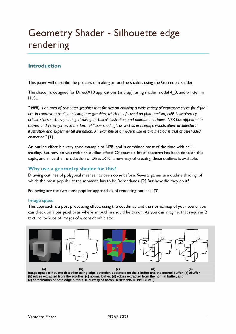
Image space This approach is a post processing effect. using the depthmap and the normalmap of your scene, you can check on a per pixel basis where an outline should be drawn. As you can imagine, that requires 2 texture lookups of images of a considerable size.
(a) (b) (c) (d) (e) Image space silhouette detection using edge detection operators on the z-buffer and the normal buffer. (a) zbuffer, (b) edges extracted from the z-buffer, (c) normal buffer, (d) edges extracted from the normal buffer, and (e) combination of both edge buffers. (Courtesy of Aaron Hertzmann4 © 1999 ACM. )
Vantorre Pieter 2DAE GD3 2
object space
One example of the object space approach works by classifying all polygons as front or back facing, store this in a hash-map, check if an edge has a front facing and a back facing triangle attached to it, and render those edges with a thickness. This requires some preprocessing, and if you have an animated model, this preprocessing has to be done each tick.
As you can see, both methods require quite some computing time, and are quite limited in their capabilities.
"Unfortunately, using shader inking has at least three drawbacks. For one, it uses only the vertex normal. Second, it can miss certain silhouette edges. And third, the varying edge thickness is very difficult to control." [4]
Geometry shader approach With DirectX10, a new shader pipeline stage has been introduced: The Geometry stage. This stage allows you to process data from triangles, lines or points, which gives you alot more possibilities for making changes to the mesh itself. Knowing this, it is definitely worth a shot to do silhouette detection with the geometry shader. Let's get started.
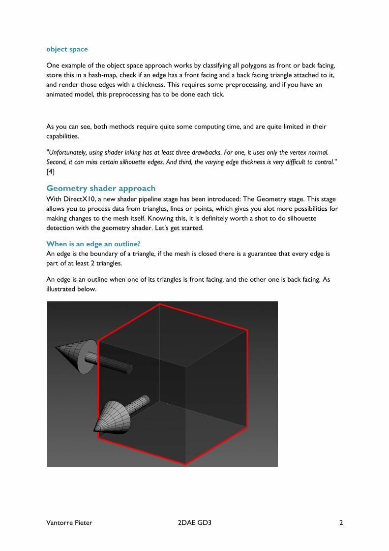
When is an edge an outline? An edge is the boundary of a triangle, if the mesh is closed there is a guarantee that every edge is part of at least 2 triangles.
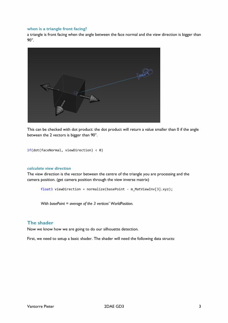
An edge is an outline when one of its triangles is front facing, and the other one is back facing. As illustrated below.
Vantorre Pieter 2DAE GD3 3
when is a triangle front facing? a triangle is front facing when the angle between the face normal and the view direction is bigger than 90°.
This can be checked with dot product: the dot product will return a value smaller than 0 if the angle between the 2 vectors is bigger than 90°.
if(dot(faceNormal, viewDirection) < 0)
calculate view direction The view direction is the vector between the centre of the triangle you are processing and the camera position. (get camera position through the view inverse matrix)
float3 viewDirection = normalize(basePoint - m_MatViewInv[3].xyz);
With basePoint = average of the 3 vertices' WorldPosition.
The shader Now we know how we are going to do our silhouette detection.
First, we need to setup a basic shader. The shader will need the following data structs:
Vantorre Pieter 2DAE GD3 4
struct VS_DATA { float3 Position : POSITION; float3 Normal : NORMAL; }; struct GS_DATA { float4 Position : SV_POSITION; float3 Normal : NORMAL; float EdgeFlag : PSIZE; };
We need the EdgeFlag parameter to make a difference between the existing geometry and the new geometry. This allows us to perform different operations in the pixel shader.
We also need the following pass through vertex shader:
VS_DATA MainVS(VS_DATA vsData) { return vsData; }
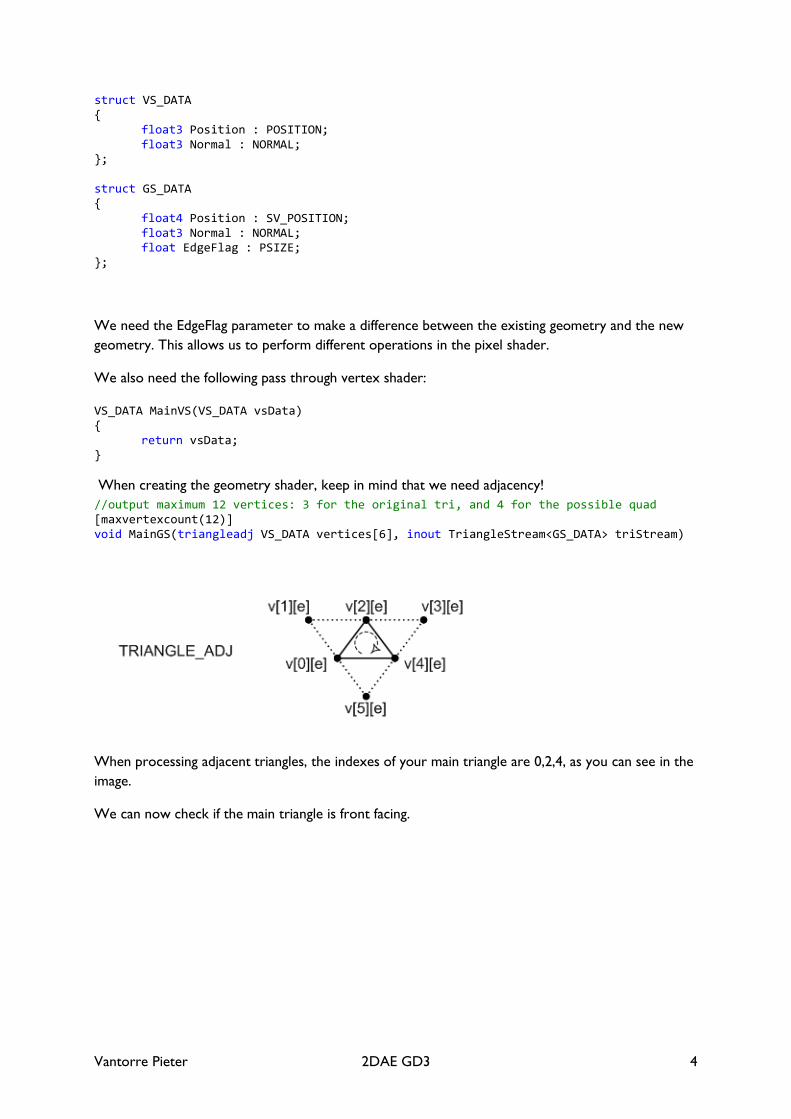
When creating the geometry shader, keep in mind that we need adjacency! //output maximum 12 vertices: 3 for the original tri, and 4 for the possible quad [maxvertexcount(12)] void MainGS(triangleadj VS_DATA vertices[6], inout TriangleStream<GS_DATA> triStream)
When processing adjacent triangles, the indexes of your main triangle are 0,2,4, as you can see in the image.
We can now check if the main triangle is front facing.
Vantorre Pieter 2DAE GD3 5
float4 wp1 = mul(float4(vertices[0].Position,1), m_MatWorld); float4 wp2 = mul(float4(vertices[2].Position,1), m_MatWorld); float4 wp3 = mul(float4(vertices[4].Position,1), m_MatWorld); // Get the normal of the current triangle float3 faceNormal = GetNormal( wp1, wp2, wp3 ); float3 basePoint = float4((wp1 + wp2 + wp3)/3).xyz; float3 viewDirection = normalize(basePoint - m_MatViewInv[3].xyz); viewDirection = normalize(viewDirection); float dotView = dot(faceNormal, viewDirection);
if(dotView < 0) {
The GetNormal method:
float3 GetNormal( float3 A, float3 B, float3 C ) { float3 AB = normalize(B - A); float3 AC = normalize(C - A); return normalize( cross(AB,AC) ); }
if the dotView is smaller than 0, it means the triangle is front facing.
We can now perform the same check for each adjacent triangle to see if they are back facing
// Iterate through the adjacent vertices - as described in the directX sample //"Direct3D10Workshop" - Exercise 2 for( uint i=0; i<6; i+=2 ) { uint iNextTri = (i+2)%6; wp1 = mul(float4(vertices[i].Position,1), m_MatWorld); wp2 = mul(float4(vertices[i+1].Position,1), m_MatWorld); wp3 = mul(float4(vertices[iNextTri].Position,1), m_MatWorld); faceNormal = GetNormal( wp1, wp2, wp3 ); basePoint = float4((wp1 + wp2 + wp3)/3).xyz; viewDirection = normalize(basePoint - m_MatViewInv[3].xyz); dotView = dot(faceNormal, viewDirection); if(dotView >= 0) {
If the adjacent tri is back facing, we know where to make a new quad!
Vantorre Pieter 2DAE GD3 6
for(int v = 0; v < 2; v++) { float3 wsPos = vertices[i].Position + v * vertices[i].Normal * m_EdgeLength; CreateVertex(triStream,wsPos,vertices[i].Normal,3); } for(int v = 0; v < 2; v++) { float3 wsPos = vertices[iNextTri].Position + v * vertices[iNextTri].Normal * m_EdgeLength; CreateVertex(triStream,wsPos,vertices[iNextTri].Normal,3); } triStream.RestartStrip();
Don't forget to always output the original 3 vertices.
//Create Existing Geometry CreateVertex(triStream,vertices[0].Position,vertices[0].Normal,0); CreateVertex(triStream,vertices[2].Position,vertices[2].Normal,0); CreateVertex(triStream,vertices[4].Position,vertices[4].Normal,0);
The CreateVertex method transforms the positions and normals of the vertices to projection space, and appends the vertices to create new geometry.
void CreateVertex(inout TriangleStream<GS_DATA> triStream, float3 pos, float3 normal, float edgeFlag = 0) { //Step 1. Create a GS_DATA object GS_DATA tempData; //Step 2. Transform the position using the WVP Matrix and assign it to (GS_DATA object).Position (Keep in mind: float3 -> float4) tempData.Position = mul(float4(pos,1),m_MatWorldViewProj); //Step 3. Transform the normal using the World Matrix and assign it to (GS_DATA object).Normal (Only Rotation, No translation!) tempData.Normal = mul(normal, (float3x3)m_MatWorld); //Step 4. Assign texCoord to (GS_DATA object).TexCoord tempData.EdgeFlag = edgeFlag; //Step 5. Append (GS_DATA object) to the TriangleStream parameter (TriangleStream::Append(...)) triStream.Append(tempData); }
Vantorre Pieter 2DAE GD3 7
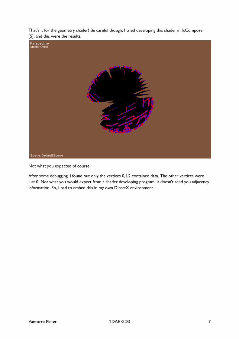
That's it for the geometry shader! Be careful though, I tried developing this shader in fxComposer [5], and this were the results:
Not what you expected of course!
After some debugging, I found out only the vertices 0,1,2 contained data. The other vertices were just 0! Not what you would expect from a shader developing program, it doesn't send you adjacency information. So, I had to embed this in my own DirectX environment.
Vantorre Pieter 2DAE GD3 8
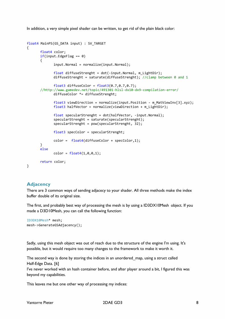
In addition, a very simple pixel shader can be written, to get rid of the plain black color:
float4 MainPS(GS_DATA input) : SV_TARGET { float4 color; if(input.EdgeFlag == 0) { input.Normal = normalize(input.Normal); float diffuseStrenght = dot(-input.Normal, m_LightDir); diffuseStrenght = saturate(diffuseStrenght); //clamp between 0 and 1 float3 diffuseColor = float3(0.7,0.7,0.7); //http://www.gamedev.net/topic/491301-hlsl-dx10-dx9-compilation-error/ diffuseColor *= diffuseStrenght; float3 viewDirection = normalize(input.Position - m_MatViewInv[3].xyz); float3 halfVector = normalize(viewDirection + m_LightDir); float specularStrenght = dot(halfVector, -input.Normal); specularStrenght = saturate(specularStrenght); specularStrenght = pow(specularStrenght, 32); float3 specColor = specularStrenght; color = float4(diffuseColor + specColor,1); } else color = float4(1,0,0,1); return color; }
Adjacency There are 3 common ways of sending adjacecy to your shader. All three methods make the index buffer double of its original size.
The first, and probably best way of processing the mesh is by using a ID3DX10Mesh object. If you made a D3D10Mesh, you can call the following function:
ID3DX10Mesh* mesh; mesh->GenerateGSAdjacency();
Sadly, using this mesh object was out of reach due to the structure of the engine I'm using. It's possible, but it would require too many changes to the framework to make it worth it.
The second way is done by storing the indices in an unordered_map, using a struct called Half-Edge Data. [6] I've never worked with an hash container before, and after player around a bit, I figured this was beyond my capabilities.
This leaves me but one other way of processing my indices:
Vantorre Pieter 2DAE GD3 9
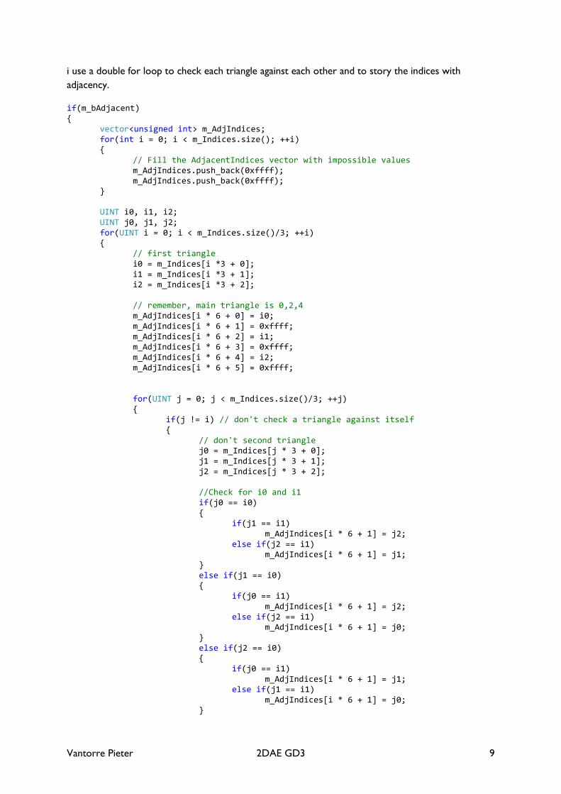
i use a double for loop to check each triangle against each other and to story the indices with adjacency.
if(m_bAdjacent) { vector<unsigned int> m_AdjIndices; for(int i = 0; i < m_Indices.size(); ++i) { // Fill the AdjacentIndices vector with impossible values m_AdjIndices.push_back(0xffff); m_AdjIndices.push_back(0xffff); } UINT i0, i1, i2; UINT j0, j1, j2; for(UINT i = 0; i < m_Indices.size()/3; ++i) { // first triangle i0 = m_Indices[i *3 + 0]; i1 = m_Indices[i *3 + 1]; i2 = m_Indices[i *3 + 2]; // remember, main triangle is 0,2,4 m_AdjIndices[i * 6 + 0] = i0; m_AdjIndices[i * 6 + 1] = 0xffff; m_AdjIndices[i * 6 + 2] = i1; m_AdjIndices[i * 6 + 3] = 0xffff; m_AdjIndices[i * 6 + 4] = i2; m_AdjIndices[i * 6 + 5] = 0xffff; for(UINT j = 0; j < m_Indices.size()/3; ++j) { if(j != i) // don't check a triangle against itself { // don't second triangle j0 = m_Indices[j * 3 + 0]; j1 = m_Indices[j * 3 + 1]; j2 = m_Indices[j * 3 + 2]; //Check for i0 and i1 if(j0 == i0) { if(j1 == i1) m_AdjIndices[i * 6 + 1] = j2; else if(j2 == i1) m_AdjIndices[i * 6 + 1] = j1; } else if(j1 == i0) { if(j0 == i1) m_AdjIndices[i * 6 + 1] = j2; else if(j2 == i1) m_AdjIndices[i * 6 + 1] = j0; } else if(j2 == i0) { if(j0 == i1) m_AdjIndices[i * 6 + 1] = j1; else if(j1 == i1) m_AdjIndices[i * 6 + 1] = j0; }
Vantorre Pieter 2DAE GD3 10
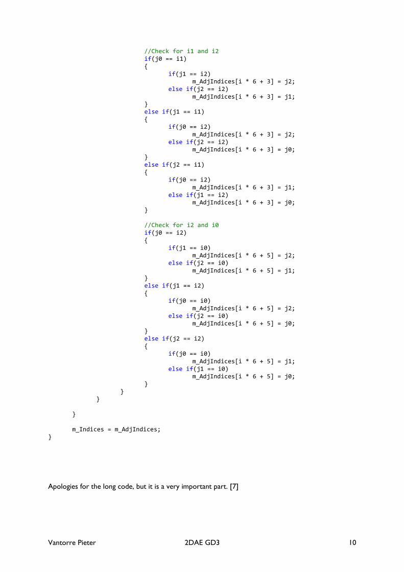
//Check for i1 and i2 if(j0 == i1) { if(j1 == i2) m_AdjIndices[i * 6 + 3] = j2; else if(j2 == i2) m_AdjIndices[i * 6 + 3] = j1; } else if(j1 == i1) { if(j0 == i2) m_AdjIndices[i * 6 + 3] = j2; else if(j2 == i2) m_AdjIndices[i * 6 + 3] = j0; } else if(j2 == i1) { if(j0 == i2) m_AdjIndices[i * 6 + 3] = j1; else if(j1 == i2) m_AdjIndices[i * 6 + 3] = j0; } //Check for i2 and i0 if(j0 == i2) { if(j1 == i0) m_AdjIndices[i * 6 + 5] = j2; else if(j2 == i0) m_AdjIndices[i * 6 + 5] = j1; } else if(j1 == i2) { if(j0 == i0) m_AdjIndices[i * 6 + 5] = j2; else if(j2 == i0) m_AdjIndices[i * 6 + 5] = j0; } else if(j2 == i2) { if(j0 == i0) m_AdjIndices[i * 6 + 5] = j1; else if(j1 == i0) m_AdjIndices[i * 6 + 5] = j0; } } } } m_Indices = m_AdjIndices; }
Apologies for the long code, but it is a very important part. [7]
Vantorre Pieter 2DAE GD3 11
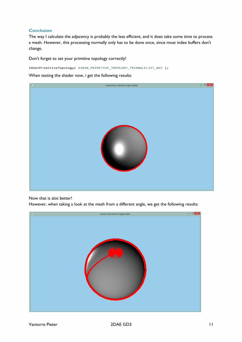
Conclusion The way I calculate the adjacency is probably the less efficient, and it does take some time to process a mesh. However, this processing normally only has to be done once, since most index buffers don't change.
Don't forget to set your primitive topology correctly!
IASetPrimitiveTopology( D3D10_PRIMITIVE_TOPOLOGY_TRIANGLELIST_ADJ );
When testing the shader now, i get the following results:
Now that is alot better! However, when taking a look at the mesh from a different angle, we get the following results:
Vantorre Pieter 2DAE GD3 12
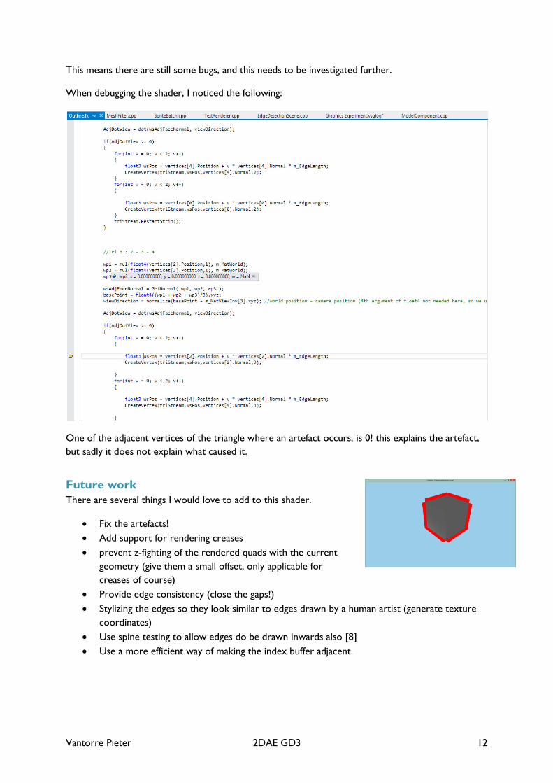
This means there are still some bugs, and this needs to be investigated further.
When debugging the shader, I noticed the following:
One of the adjacent vertices of the triangle where an artefact occurs, is 0! this explains the artefact, but sadly it does not explain what caused it.
Future work There are several things I would love to add to this shader.
• Fix the artefacts! • Add support for rendering creases • prevent z-fighting of the rendered quads with the current
geometry (give them a small offset, only applicable for creases of course)
• Provide edge consistency (close the gaps!) • Stylizing the edges so they look similar to edges drawn by a human artist (generate texture
coordinates) • Use spine testing to allow edges do be drawn inwards also [8] • Use a more efficient way of making the index buffer adjacent.

Vantorre Pieter 2DAE GD3 13
Conclusion I learnt alot by making this shader. Now i truely understand the different spaces a model can be in, and the use of the different matrices used by the shader. I learnt to process indices with adjacency, how to debug shaders in Visual Studio, how to find edges of a model and alot more.
I am not satisfied with the results of this paper, because I still have the artefacts that make this shader quite useless. If these artefacts are fixed however, I will be able to further develop this shader.
Finding silhouette edges is also the basic of using shadow volumes, only there you check if the triangles are back facing from the light and not from the camera. I will try to implement shadow volumes later on.
Thank you for reading
Bibliografy
[1] „Non photorealistic rendering,” Wikipedia, [Online]. Available: http://en.wikipedia.org/wiki/Non-photorealistic_rendering.
[2] [Online]. Available: http://www.borderlandsthegame.com/.
[3] I. e. a. 2003, „A Developer’s Guide to silhouette algorithms for polygonal models,” [Online]. Available: http://www.inf.hs-anhalt.de/~schlechtweg/home/pdf/Isenberg.2003.ADG.pdf.
[4] J. Doss, „Inking the Cube: Edge Detection with Direct3D 10,” Gamasutra, 2008. [Online]. Available: http://www.gamasutra.com/view/feature/130067/sponsored_feature_inking_the_.php.
[5] „Fx Composer,” Nvidia, [Online]. Available: https://developer.nvidia.com/fx-composer.
[6] „Half Edge Data Struct,” [Online]. Available: http://www.cgal.org/Manual/latest/doc_html/cgal_manual/HalfedgeDS/Chapter_main.html.
[7] [Online]. Available: http://www.gamedev.net/topic/499275-good-news-read-please-how-to-generate-adjacency/.
[8] [Online]. Available: http://gfx.cs.princeton.edu/pubs/Cole_2010_TFM/.
[9] P. H. &. P. Vázquez. [Online]. Available: http://cgstarad.com/Docs/GSContours.pdf.
[10] P. Rideout. [Online]. Available: http://prideout.net/blog/?p=54.
[11] K. Hayton. [Online]. Available: http://www.khayton-portfolio.com/samples_silhouette.html.