GEOMETRY PROCESSOR GRAPHICS - IEEE Computer · PDF fileAVLSI GEOMETRY PROCESSOR FORGRAPHICS...
8
Emphasizing ease of scaling and sharing of design tools, a new approach to VLSI systems design may deliver inexpensive specialized hardware. SPECIAL FEATURE A VLSI GEOMETRY PROCESSOR FOR GRAPHICS James Clark Stanford University Most graphics systems must do some geometric processing. Three tasks they frequently share are coordinate transformations of objects, clipping transformed objects to the boundaries of the viewing window, and scaling clipped objects to the viewport of the destination drawing device. The last of these functions often includes perspective division. For real-time line and character graphics, these opera- tions are the most significant computation-intensive tasks. Unless they are done in a parallel way, such as in hardware, the graphics system has no hope for real- time operation. The hardware to do these tasks is, of course, special-purpose, so the cost of real-time two- and three-dimensional graphics systems is relatively ex- pensive compared to the costs of microprocessor systems. Until recently, there has been no significant VLSI development in the special-purpose domain corresponding to the microprocessor in the general- purpose domain. The introduction of a new approach to VLSI design, set forth in the book Introduction to VLSI Systems,' is changing this situation. Several major university projects are now under way that have used this approach to develop a custom VLSI processor or system. One such project, being done at Stanford, has the goal of making a 12-chip system that performs the common geometric functions described above. A single chip type is used in 12 slightly different con- figurations to accomplish 4 X 4 matrix multiplica- tions; line, character, and polygon clipping; and scal- ing of the clipped results to display device coor- dinates. The system will do these functions in a highly parallel organization having an effective A different version of this article appeared in LAMBDA-The Magazine of VLSI Design, Vol. 1, No.2, (3 1980. Reprinted by per- mission. operation rate of about four million floating-point operations per second; 48 identical units, four per chip, each will do a floating-point operation in about 12 microseconds. Thus, the system will transform, clip, and scale incoming floating-point 2-D or 3-D coordinates representing endpoints of lines or ver- tices of polygons at a rate of about 3500 lines, or 900 polygons, every 1/30 second. The single chip type that is the basis of the system is referred to as the Geometry Engine. The Geometry Engine is a vector function unit that allows simple operations on floating-point numbers. It consists of four identical function units, each hav- ing an 8-bit characteristic and (presently) a 20-bit mantissa. It accomplishes this with a very simple structure consisting of five elements-an ALU, three registers, and a stack. The 12-chip system will consist of 1344 copies of a single bit-slice layout of these elements. The Geometry Engine does parallel adds, sub- tracts, and similar two-variable operations on either the mantissa or the characteristic; since one of the registers can shift down and one can shift up, it can also do multiplies and divides at the rate of one multiply or divide step per microcycle. Four pins on the chip will be wired to tell its microcode which of the 12 functions it is to do, according to its position in the subsystem organization. After briefly discussing the graphics functions to be accomplished by the system, we will present a brief history of its development to date, with special emphasis on the architecture/design considerations motivated by the use of NMOS. Some of the reasons for choosing the system timing convention of Seitz2 will also be discussed. Finally, we will draw some con- clusions about the feasibility of having just one per- son (or a small number of people) do the architecture, circuit design, and layout of a VLSI system. July 1980 59
Transcript of GEOMETRY PROCESSOR GRAPHICS - IEEE Computer · PDF fileAVLSI GEOMETRY PROCESSOR FORGRAPHICS...

Emphasizing ease of scaling and sharing of design tools,a new approach to VLSI systems design may deliver
inexpensive specialized hardware.
SPECIAL FEATURE
A VLSI GEOMETRYPROCESSOR
FOR GRAPHICS
James ClarkStanford University
Most graphics systems must do some geometricprocessing. Three tasks they frequently share arecoordinate transformations of objects, clippingtransformed objects to the boundaries of the viewingwindow, and scaling clipped objects to the viewportof the destination drawing device. The last of thesefunctions often includes perspective division. Forreal-time line and character graphics, these opera-tions are the most significant computation-intensivetasks. Unless they are done in a parallel way, such asin hardware, the graphics system has no hope for real-time operation.The hardware to do these tasks is, of course,
special-purpose, so the cost of real-time two- andthree-dimensional graphics systems is relatively ex-pensive compared to the costs of microprocessorsystems. Until recently, there has been no significantVLSI development in the special-purpose domaincorresponding to the microprocessor in the general-purpose domain. The introduction of a new approachto VLSI design, set forth in the book Introduction toVLSI Systems,' is changing this situation. Severalmajor university projects are now under way thathave used this approach to develop a custom VLSIprocessor or system.One such project, being done at Stanford, has the
goal of making a 12-chip system that performs thecommon geometric functions described above. Asingle chip type is used in 12 slightly different con-figurations to accomplish 4 X 4 matrix multiplica-tions; line, character, and polygon clipping; and scal-ing of the clipped results to display device coor-dinates. The system will do these functions in ahighly parallel organization having an effective
A different version of this article appeared in LAMBDA-TheMagazine of VLSI Design, Vol. 1, No.2, (3 1980. Reprinted by per-mission.
operation rate of about four million floating-pointoperations per second; 48 identical units, four perchip, each will do a floating-point operation in about12 microseconds. Thus, the system will transform,clip, and scale incoming floating-point 2-D or 3-Dcoordinates representing endpoints of lines or ver-tices of polygons at a rate of about 3500 lines, or 900polygons, every 1/30 second. The single chip typethat is the basis of the system is referred to as theGeometry Engine.The Geometry Engine is a vector function unit that
allows simple operations on floating-point numbers.It consists of four identical function units, each hav-ing an 8-bit characteristic and (presently) a 20-bitmantissa. It accomplishes this with a very simplestructure consisting of five elements-an ALU, threeregisters, and a stack. The 12-chip system will consistof 1344 copies of a single bit-slice layout of theseelements.The Geometry Engine does parallel adds, sub-
tracts, and similar two-variable operations on eitherthe mantissa or the characteristic; since one of theregisters can shift down and one can shift up, it canalso do multiplies and divides at the rate of onemultiply or divide step per microcycle. Four pins onthe chip will be wired to tell its microcode which of the12 functions it is to do, according to its position in thesubsystem organization.After briefly discussing the graphics functions to
be accomplished by the system, we will present abrief history of its development to date, with specialemphasis on the architecture/design considerationsmotivated by the use of NMOS. Some of the reasonsfor choosing the system timing convention of Seitz2will also be discussed. Finally, we will draw some con-clusions about the feasibility of having just one per-son (or a small number of people) do the architecture,circuit design, and layout of a VLSI system.
July 1980 59

What does the system do?
The three geometric operations that almost everygraphics system must do are illustrated in Figure 1.The first is transformations. Typically, "objects," orpicture subroutines, are defined using such primi-tives as lines, characters, or polygons. These picturesubroutines are usually defined in their own localframe of reference, or coordinate system, since thismakes their definition more general; i.e., their coordi-nates can be entered without regard to how they even-tually might be drawn on the destination display.Thus, the first thing that happens to the objects ontheir way from object memory to the display is a trans-formation of their coordinates, usually into an in-termediate coordinate system convenient for clipping.A convenient way to accomplish this transforma-
tion is with a 4 X 4 matrix. The motivation for thischoice is treated very well in the excellent graphicstextbook, Introduction to Computer Graphics.3 A4 X 4 matrix allows rotations, scaling, translations,and a number of other transformations to be donewith a single entity. It also conveniently handlesboth two- and three-dimensional objects, and two
Figure 1. Three basic operations performed by a graphics system:transformation, clipping, and scaling.
successive transformations can be composed by asimple multiplication of their transformationmatrices. Four Geometry Engines can transform anincoming four-component vector into a four-component vector expressed relative to a coordinatesystem that is "fixed to the observer." Figure 2shows a block diagram of the subsystem organiza-tion; each of the four mm blocks is a separateGeometry Engine chip that does a four-componentvector-dot product. Although each multiply is doneat the rate of one partial product per microcycle, thematrix multiplier has 16 of these products simulta-neously active. Thus, the total transformation time,which is the bandwidth limiting the operation of thesystem, is about 12 microseconds.After transformation, the objects are expressed
relative to a virtual drawing coordinate system inwhich the viewing window is specified. In two dimen-sions, this window is as shown in Figure 1. In threedimensions, the window is a set of planes extendingoutward from the eye of the observer; these planescan be thought of as extending through the rectangledefined by the 2-D boundaries shown in the figure;i.e., the observer sees the planes on edge. This windowrepresents the part of the picture to be mapped ontothe destination display. Objects-points, lines,characters, and polygons (sequences of lines)-are"clipped" to the planes, or window boundaries, oneplane at a time in pipeline fashion (indicated in Figure2 by the clip n units).In the clipper configuration, a Geometry Engine
holds the plane equation for both endpoints of the linein one of its function units, while it holds the 2-D or3-D coordinates for the endpoints in its other threeunits. The sign of the plane equation for each pointtells which side of the plane the point is on. By con-vention, this sign is negative if the point is on the"out" side of the plane, meaning that it is not visibleto the observer because it is outside of the window.Thus, a line segment having both signs negative iscompletely out of the viewing area, while one havingboth signs positive is completely in. The clipperdiscards segments completely outside its plane,passes segments that are completely inside to thenext clipper chip, or finds the point of intersection ofthe segment with the plane and passes the results onto the next clipper chip.In the clipper configuration, the Geometry Engine
first determines if a line is to be discarded or passedon to the next unit, as shown in Figure 3. Since thesetwo cases are the most common, a clipper chiptypically will spend very little time "clipping." Thus,one might say that the clipper chip spends most of itstime "sailing." When a segment crosses a plane, theengine finds the intersection point by a logarithmicsearch for the point. That is, on each microcycle eachof the four units (the plane equation unit and the threecoordinate units) computes the midpoint of itsrepresentation of the line. Choosing one of the end-points as a reference point, the engine then deter-mines if the midpoint is on the same side of the planeas this reference point. If so, the reference point is up-dated by moving it to the midpoint. This is repeated
COMPUTER

until the precision of the mantissa is reached. The al-gorithm is similar to that devised by Sproull andSutherland.4The final geometric function is scaling (see bottom
of Figure 1). This operation scales objects that re-main after clipping from the window to a viewport;the viewport is expressed in the integer coordinatesystem of the destination display. In three dimen-sions, both perspective division and scaling todestination device coordinates simultaneously takeplace. In two dimensions, only scaling is done. Theperspective division/scaling operation requires twofunction units for each coordinate; thus, oneGeometry Engine works for two coordinates, since ithas four function units. The operation is done by us-ing one of the units; it accomplishes the division byarriving at the successive bits of the quotient one at atime, starting with the most significant bit. Ratherthan being accumulated, however, the bits are usedimmediately to determine whether to add the suc-cessive partial products of the viewport scale usingthe other function unit. For example, in the equation
X = (x/w)*Vsx + Vcx,
which is the scaling operation for the x coordinate,one unit computes the quotient x/w one bit at a time,starting with the most significant bit, while the otherunit uses these successive bits to govern the ac-cumulation of the product of this quotient with Vsx.In this way, the perspective division and the multipli-cation of the scaling operation are done simultane-ously. Moreover, since the output device typicallyhas no more than 12 bits of precision, this operationmay stop after 12 microcycles. Then Vcx is added tothe accumulated result. As in the clipper mode of op-eration, the algorithm used is similar to that de-scribed in Sproull and Sutherland.4
A brief design history
Architecture. In July of 1979, Carver Mead of Cal-tech and Lynn Conway and several people from theLSI Systems Group of Xerox Palo Alto ResearchCenter presented an intensive, three-day course on
designing NMOS circuits to some of the faculty andstaff of Stanford. In search of a project, the authorrecalled that the Clipping-Divider, designed and builtby Sproull and Sutherland4 in the early days of SSI,was a relatively high-performance device that oper-
ated with a clock cycle of approximately 200 ns. It at-tained its high performance by having four units op-
erate in parallel, each doing a clip operation some-
what like that described above. Unlike the presentplane-at-a-time configuration, however, the unitswere tightly linked together in a configuration thatsimultaneously clipped lines to the four windowboundaries. (The plane-at-a-time notion is due toSutherland and Hodgman.5) Figure 4 shows an ap-
proximate diagram of this organization. The projectchosen was to implement the Clipping-Divider as a
single NMOS chip.
Figure 2. Data flow in the graphics geometry subsystem. Each of thefour mm blocks is a separate Geometry Engine chip that does a four-component, vector-dot product.
Figure 3. Logarithmic search for an intersection point todetermine if a line is to be discarded or passed on to thenext unit.
A single bit slice for the machine was designed us-ing an interactive circuit layout program. Thislayout, using Mead/Conway design rules at lambda= 3 microns, would require a 80-mm2 chip. In addi-tion, it was unappealing because the architecture in-
July 1980 61

Figure 4. Rough diagram of Sproull and Sutherland's original Clipping-Divider.
THE SHADED AREAS HAVE ACTUALY BEEN MtPEMENTEM.
Figure 5. Plan view of the Geometry Engine.
volved a large amount of interconnecting wiringwithin the bit slice. This wiring consumed as mucharea as the functional units of the bit slice, making itabout twice as wide as it might otherwise be.
In addition to these drawbacks, there was the an-noying problem of transformations. A completegraphics system needs transformations as well asclipping and scaling, and the Clipping-Divider did on-ly the latter functions. Another problem was the feel-ing that a good user interface would require that thecoordinates supplied to the transformation unit befloating-point.
In a discussion of the problem with Jim Rowson ofCaltech, he suggested that, for simplicity, the clip-ping be done one plane at a time. Since puttingeverything on one chip was a (unreasonable) projectgoal, this at first seemed undesirable. Since theauthor was aware of the Reentrant Polygon Clipper,5however, it was clear that this scheme would have anadvantage in that it would work for polygons as wellas lines. That is, by pipelining the clipping operationand keeping a small amount of additional informa-tion and clipping to one plane at a time, it is possibleto clip polygons and lines. The original Clipping-Divider algorithm worked only with lines.Keeping everything on one chip was still a goal. The
next major step came with the realization that asystem like the Clipping-Divider actually does amultiplication in the scaling mode. In the divide/scaleoperation described in the previous section, one oftwo units accumulates the partial products of amultiplication while the other generates bits of a quo-tient. However, two units are required in this modebecause one is doing a division. A solution 'wasachieved by making a simple bit slice with oneregister that shifts up, in addition to the one thatshifts down in the clipper mode, so that one unit coulddo multiplication as well as the division implicit in theclipping mode. Moreover, since a single-plane clipperrequires four function units, as described above, andsince four function units can also simultaneouslymultiply four numbers, it was clearly possible to havea single chip that could do a four-component vector-dot product as well as a single-plane clipping opera-tion.The final step toward making a single chip to ac-
complish these functions came when it wasdiscovered that both an exponent and a mantissawould conveniently fit on either side of the controlpart of the unit, i.e., the programmable logic array (asshown in Figure 5). With one exception, the basic ar-chitecture was fixed at this point.The exception was that no provision had been made
for a matrix stack. A matrix stack allows structuredpictures. It pushes away a current transformationmatrix before going to a "picture subroutine" inmuch the same way that arguments are saved in go-ing to a recursive subroutine in a regular program. Itprovides a picture hierarchy capability. It wasoriginally thought that the matrix stack would be toospace consuming to put on the chip and that it reallybelonged on a separate stack chip. When the time hadcome to consider the issue more seriously, however, it
COMPUTER
INTERCONNECTIONS
62
Ito m r | | was discovered that puttingthe stackon aseparatechip caused a lot of communication problems.
CD, Observe from Figure 2 that the organization has a- i l i W 1 clean, pipeline flow without an external matrix stack.
To place a matrix stack chip so that matrices can be9 l 1! 1& transferred from themm chips on a PUSH command
s~ ' | | and back to the mm chips on a POP command inter-rupts this flow and requires more complicated buscommunication paths.
In puzzling over this need for a stack, the authorrealized that the best place for it, to simplify com-munication, was in the bit slice. Provision had al-ready been made for several extra storage registers inthe bit slice in addition to the accumulator (A), upshifter (U), and down shifter (D). Because the func-tion units, when operating as a polygon clipper,needed several save-point registers, the bit slice atthis time had two additional storage registers, S1 andS2. After actually doing a layout of a variant of thestack cell given in Mead and Conway's book, it wasevident that about nine stack cells took only slightlymore space than the two register cells. This was large-ly due to the need for fewer control lines. Also, sincethe top two elements of the stack were still useful forthe temporary save-point registers, it was clear thatthe stack belonged with the bit slice. In other words,the bit slice became a microrepresentation of the en-
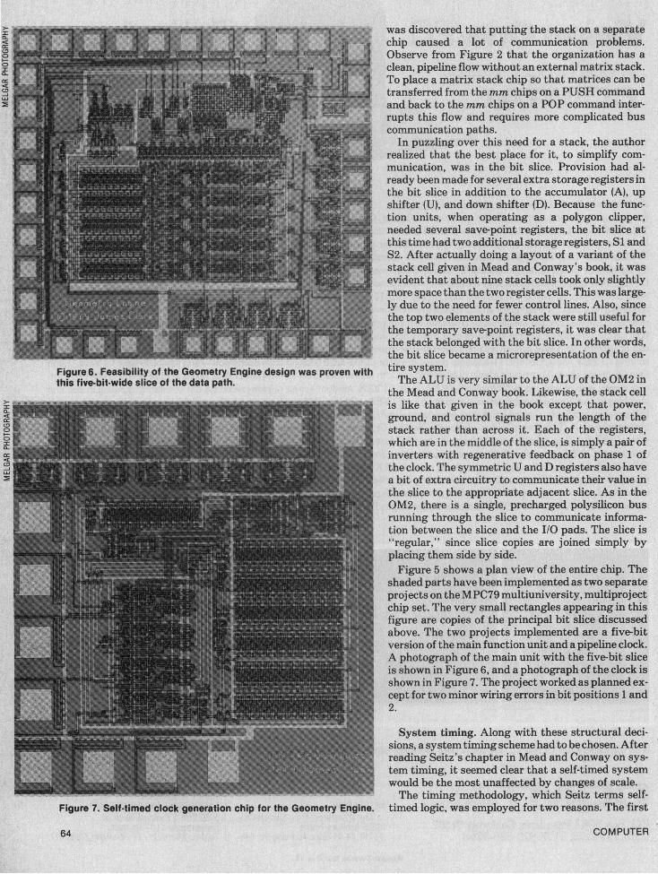
Figure 6. Feasibility of the Geometry Engine design was proven with tire system.this five-bit-wide slice of the data path. The ALU is very similar to the ALU of the OM2 in
the Mead and Conway book. Likewise, the stack cell>I _iis like that given in the book except that power,
<: < , ground, and control signals run the length of the°> stack rather than across it. Each of the registers,
which are in the middle of the slice, is simply a pair ofinverters with regenerative feedback on phase 1 ofthe clock. The symmetric U and D registers also havea bit of extra circuitry to communicate their value inthe slice to the appropriate adjacent slice. As in theOM2, there is a single, precharged polysilicon busrunning through the slice to communicate informa-tion between the slice and the I/O pads. The slice is"regular," since slice copies are joined simply byplacing them side by side.Figure 5 shows a plan view of the entire chip. The
shaded parts have been implemented as two separateprojects on theMPC79 multiuniversity, multiprojectchip set. The very small rectangles appearing in thisfigure are copies of the principal bit slice discussedabove. The two projects implemented are a five-bitversion of the main function unit and a pipeline clock.A photograph of the main unit with the five-bit sliceis shown in Figure 6, and a photograph of the clock isshown in Figure 7. The project worked as planned ex-cept for two minor wiring errors in bit positions 1 and2.
System timing. Along with these structural deci-sions, a system timing scheme had to be chosen. Afterreading Seitz's chapter in Mead and Conway on sys-tem timing, it seemed clear that a self-timed systemwould be the most unaffected by changes of scale.The timing methodology, which Seitz terms self-
Figure 7. Self-timed clock generation chip for the Geometry Engine, timed logic, was employed for two reasons. The first
COMPUTER64

was to avoid the clock skew problems associated withdistributing a clock over a very large circuit. Al-though clock distribution is not a problem at the4-Jn-line dimensions atwhich the circuits will initiallybe implemented, clock skew does become a problemat the 1-JAm-line dimensions that eventually will beused to scale the entire project onto a single chip.With a self-generated clock on each of the 12 originalchips, the scaled system will have 12 separatelytimed subsystems. Moreover, because of the de-creased scale, it will run approximately four times asfast.The other reason for using self-timing was to avoid
synchronization failure. Since a separate clock istightly coupled with the control of each chip, theclock can be synchronously stopped when the unit isidle, waiting for input, or waiting for output to betaken. It can be asynchronously started by the uniton which it is waiting when the unit is ready. This
avoids synchronization failure and allows the clockcycle to be varied according to the needs of the par-ticular microinstruction. The clock chip worked en-tirely as planned. Only the most complicated part ofthe design remained: writing the microcode for thePLA control.
Microprogramming
The Geometry Engine is a quasi-general-purpose,four-component vector function unit. It gets itspower from its architectural simplicity; almost all itscomplexity is in the microcode that drives it. Thismicrocode is a representation of the logic equationsfor its finite state machine, implemented in a pro-grammable logic array. Writing this microcode andmaking minor additions to the principal bit slice to
A language for microcode description andsimulation in VLSI
John HennessyStanford University
Use of the structured design methodology advo-cated by Mead and Conway in Introduction to VLSISystems' leads to chip architectures that employmicrocoded control implemented with a program-mable logic array. Several recent VLSI chip designs-including Clark's Geometry Engine2 and the MITScheme Chip3-have used a design approach basedon a microprogrammed engine. With such an ap-proach, the microprogramming becomes of centralimportance to the design. Few tools currently exist toassist the designer in implementing and debuggingthis microcode. The Scheme Chip Project createdspecial-purpose tools for this purpose. Here we will'discuss a similar set of tools-a language and sys-tem which provide microcode simulation and au-tomated PLA generation. Although this project wasinitiated to support the design of the GeometryEngine, it is a general tool and therefore useful in anymicroprogramming situation where the final im-plementation technique is PLA-based.
Design of microcode within a chip is a tedious anderror-prone task for several reasons. First, theprogramming language is extremely low-level. Thedesigner must deal with a binary machine without thebenefit of a human-engineered interface. Second,many of the microprograms are large, leading to acomplex program lacking in structure. Without ahigher-level standard representation, microprogramsare difficult to comprehend and write correctly.To provide effective simulation of microcode, the
language must provide a description of the environ-ment with which the microcode interacts. Thismicromachine description should be separate from
the environment description, because it increases com-prehensibility of the microcode and because a special-ized language is more appropriate for microprogramdesign.
Given the PLA terms, laying out a PLA manually isboth time-consuming and tedious, leading to unneces-sary errors. However, the process is mechanicallystraightforward. Therefore, a microprogramming lan-guage should provide for automated PLA layout as wellas microcode design.
Since the end product of this design is a FSM- finitestate machine-implemented with PLA techniques, amethod of incorporating details about the implementa-tion is required. This specification should include map-pings between functional specifications in the environ-ment and actual PLA outputs, as well as "pipelining"specifications which force outputs to occur earlier orlater than they occur in the program. Details concerningthe actual PLA layout are also needed, including suchthings as the number of PLAs and the positioning ofeach signal on the PLA.
Defining the micromachine. The description of amicrocoded machine has three major parts: the environ-ment, the FSM control, and the PLA definition and map-ping. The environment describes the other functionalunits controlled by the PLA and is used for simulation.The FSM control defines the outputs and next state ac-tions in the FSM. The PLA description specifies thedetails about the PLA and the mapping between the FSMinputs/outputs and the PLA input/outputs.The environment of the FSM is described in a conven-
tional programming language; it must interface with themicromachine specification both for simulation andgeneration of the PLA. The environment consists ofvariables, procedures, and functions which can be usedto simulate the structure of the subsystems. The en-vironment/controller interface is based on a set of func-tions and procedures. The functions, which must betype boolean, correspond to the inputs to the machine,while the procedures correspond to output signals. We
COMPUTER66

accommodate its requirements have taken approxi-mately 50 percent of the total design time.Design tools in the VLSI design business are still
relatively crude, one of the reasons for the emphasison regular structures in the Mead and Conway book.Experience with the project has shown thatwhen onehas a very homogeneous architecture that minimizesthe layout problem for the main function unit, themost needed design tool is a mechanism for simula-ting the microcode and thence automatically genera-ting a PLA layout from the simulated code. Althoughothers had recognized this need, until recently no onehad provided a well-structured language with asuitable PLA-generating post-processor.A Pascal-based language for this purpose has been
written by Hennessy at Stanford (see box below),and the author has added the PLA generation post-processor.7 This language has two modes of opera-tion-simulation and PLA generation. In the simu-
lation mode, the user defines with Pascal pro-cedures an-algorithmic statement of the function ofthe "environment" driven by the logic equations ofthe microarchitecture. All PLAs are named, with thename providing,their layout orientations and their in-put and output signals with their polarities; for addi-tional convenience, the signals may be labeled as"pipelined," thereby relieving the microprogrammerof worries related to pipelining. The microprogram isthen written in a simple, clean form. The microcode istranslated into Pascal procedures, loaded with the en-vironment procedures, and the result is thensimulated. After satisfactory simulation of themicrocode, the user runs the system in the PLAgeneration mode and the Caltech Intermediate Formfor the PLA layout is output. This form is thenmerged with the layouts of the function units beingdriven by the microcode, and the merged layouts arewired together.
have chosen Pascal as the language for environmentdescription.The microcode is organized as a FSM; a next state
function specifies control flow. To simplify thedesigner's interaction, a default next state is provided.There are at least two major schemes for implementing aFSM which must be considered: a standard finite stateimplementation with a fixed state assignment, and animplementation based on a microcode engine with amicroprogram counter. It is useful to support both ofthese implementation schemes, since each has advan-tages in different situations.
Microcode specification. The micromachine is de-fined as a set of sequentially listed states. Each statecan have a label denoting the state name. The statespecifications are preceded by a set of specifications forstate-independent outputs.
Each state consists of a list of state specifications. Astate specification is similar to a guarded command; itconsists of a predicate part or guard and a list of actions.A guard is a product term whose individual componentsare boolean functions, which are associated with PLA in-puts. If all the predicates are true, the actions should beexecuted. If there are no predicates, the guard is as-sumed to be true and the action is always executed inthat state.
There are two types of actions allowed: outputs andstate change operations. Outputs are invocations of pro-cedures in the environment and correspond to PLA out-puts. The state change directives dictate the next stateand also provide microcode subroutines.To define the relationship between the microcode
specification of the control program and the PLA, thereare three types of things to specify: the input signals,the output signals, and the mapping between environ-ment functions and procedures and I/O signals. PLAsignals are defined by input and output signal declara-tions. Input and output signals are associated with en-vironment functions and procedures by means of signaldefinitions, which appear with the function/procedure
definition. Procedures in the environment without adefinition section are used for simulation purposesonly. The signal definitions provide limited patternmatching, actual parameter substitution, and recur-sively defined patterns.
An implementation. The description language canbe used to drive a microcode sumulation as well asgenerate a PLA layout. In order to do simulation, themicrocode description is supplied with the signaldeclarations and definitions. A single languagetranslator forms the front end for either a microcodesimulation or PLA generation. Presently, simulationis done by creating a Pascal program embodying thesemantics of the microcode.PLA generation is done in two parts. The front end
analyzes the microcode structure and creates prod-uct term lists for each output. The effect of signaldefinition and pipelining is taken into account beforemaking these lists. The PLA layout is then done by aseparate program which inputs the signal descrip-tions and the product term lists. This structure allowsthe insertion of programs which optimize the FSM.
The language and processing system describedhere-whose implementation orientation is PLA-based-documents the microcode at a reasonablelogical level while providing a firm specification toallow extensive simulation, debugging, and error de-tection. It automatically creates the PLA layout need-ed to implement the microcode description.
1. C. A. Mead and L. Conway, Introduction to VLSISystems, Addison-Wesley, Reading, Mass., 1980.
2. J. Clark, "A VLSI Geometry Processor for Graphics,"Computer, this issue.
3. J. Holloway, G. Steele, and G. Sussman, "TheScheme-79 Chip," paper read at MIT Conf. on AdvancedResearch in Integrated Circuits, Cambridge, Mass., Jan.1980.
July 1980 67

DoesVLSI Architecture
Interest You?
The article "A VLSI Geometry Processor For Graphics"by Dr. James H. Clark appearing in this issue is justa sample of the exciting developments you'll find ineach issue of LAMBDA, the magazine of VLSI design.
LAMBDA is a new quarterly publication bringing youthe latest news and developments in VLSI design.LAMBDA is your one-stop source for informationin this dynamic field.
You get clear, concise coverage of:* Design automation for VLSI.* Case histories of new chip designs.* New digital system architectures.* IC fabrication techniques.* Testing aids and strategies.* The latest developments in university and
industrial research centers.
LAMBDA Magazine is helping to lead this fast-changing field. Don't miss the next issue. Subscribeto LAMBDA today!
Act now. Mail coupon to LAMBDA Magazine, P.O. Box50503, Palo Alto, California 94303.
C1 4 issue (1 year)-$16 0 8 issues (2 years)-$30
0 Bill me. C Bill company. C Check enclosed.
Name
Title
Company
Address
City
State Zip
Address is for D home C company.
Above, rates apply only to U.S.A. Foreign rates: Canada and Mexico-$18/year and $34/2 years; Europe and South America - $25/year and $4812years; Japan and Middle East- 527/year and $52/2 years. Rates forcountries other than U.S.A., Canada and Mexico include air mail delivery. Allpayments must be in U.S. dollars.
The flexibility of structuring one's own buildingblocks to implement a specially conceived architec-ture is one of the key features of the Mead and Con-way approach. Their book and the courses taughtfrom it are encouraging a rapid evolution of sharabledesign tools at several major universities and corpor-ations. As a result, small groups, or even individuals,may soon be able to design, simulate, create thelayout for, and readily implement new architectures.The graphics community will benefit from this
trend. Many imaging functions, for example, arehighly repetitive and therefore suitable for special-ized hardware. We can expect that in a few years onewill be able to have a high-performance graphicssystem for not much more than the cost of today'spersonal computers.E
AcknowledgmentsI thank Lynn Conway ofXerox for making available
the resources of her LSI Systems Group, enablingmeto quickly learn the material. Martin Newell was ex-tremely helpful as a source of encouragement and in-sight.
References
1. C. A. Mead and L. Conway, Introduction to VLSISystems, Addison-Wesley, Reading, Mass., 1980.
2. C. L. Seitz, "System Timing," in C. A. Mead and L.Conway, Introduction to VLSI Systems, Addison-Wesley, Reading, Mass., 1980, pp. 218-262.
3. W. M. Newman and R. F. Sproull, Principles of In-teractive Computer Graphics, 2nd ed., McGraw-Hill,New York, 1979.
4. R. F. Sproull and I. E. Sutherland, "A ClippingDivider," AFIPS Conf Proc., Vol. 33, 1968 FJCC,p. 765.
5. I. E. Sutherland and G. W. Hodgman, "ReentrantPolygon Clipping," Comm. ACM, Vol. 17, No. 1, Jan.1974, pp. 32-42.
6. L. A. Conway, A. G. Bell, and M. E. Newell, "MPC79:The Demonstration-Operation ofa Prototype Remote-Entry Fast-Turnaround, VLSI Implementation Sys-tem," paper read at MIT Conf. on Advanced Researchin Integrated Circuits, Cambridge, Mass., Jan. 1980.
7. J. Hennessy, "Microprogram Simulation/PLA Com-pilation," paper read at Stanford Computer Forum,1980.
James H. Clark joined the ElectricalEngineering Department at StanfordUniversity in 1979 to do research inVLSI systems architecture. He was as-sistant professor at the University ofCalifornia at Santa Cruz from 1974 to1977, and a consultant from 1978 to1979.j. 1 e_Anactive researcher in computergraphics sin,e 1973, Clark has exten-
sive experience in building both hardware and softwarecomputing systems. His current research interests are invery low-cost personal computers, high-performance 2- and3-D graphics, VLSI system architecture, and VLSI designaids.
COMPUTER