
GEOMETRY-BASED UNDERSTANDING OF …...relation between form and forces with diagrams linked through...
11
JOURNAL OF THE INTERNATIONAL ASSOCIATION FOR SHELL AND SPATIAL STRUCTURES: J. IASS 285 GEOMETRY-BASED UNDERSTANDING OF STRUCTURES Tom VAN MELE 1 , Lorenz LACHAUER 2 , Matthias RIPPMANN 3 and Philippe BLOCK 4 1 Postdoctoral Researcher, Institute of Technology in Architecture, ETH Zurich, Switzerland, [email protected] 2 Research Assistant, Institute of Technology in Architecture, ETH Zurich, Switzerland, [email protected] 3 Research Assistant, Institute of Technology in Architecture, ETH Zurich, Switzerland, [email protected] 4 Assistant Professor, Institute of Technology in Architecture, ETH Zurich, Switzerland, [email protected] Editor’s Note: Manuscript submitted 27 January 2012; revision received 2 October 2012; accepted 28 October. This paper is open for written discussion, which should be submitted to the IASS Secretariat no later than June 2013. ABSTRACT The development of structures with complex, curved geometry is a complicated process in which spatial and structural considerations are often addressed separately. This paper describes the possibilities of an integrated approach to the form finding of such structures that is based on geometrical rather than analytical or numerical representations of the relation between form and forces. The approach adopts key principles of graphic statics and extends them with the latest research on form finding, structural design and optimisation techniques. Through a series of examples, the paper demonstrates that with implementations of this approach in constraint- based and parametric software, powerful tools can be created for shape and equilibrium explorations of two- and three-dimensional structural systems. These tools provide continuous, bi-directional control over both spatial and structural characteristics, through an intuitive, visual language that is equally accessible to architects and engineers, and can be used in research and professional practice as well as in teaching. Keywords: Structural geometry, structural equilibrium, interactive graphic statics, form finding. 1. INTRODUCTION The development of non-standard building shapes that have strong spatial qualities while being structurally efficient is not a straightforward process, requiring several iterations of design and post-rationalisation. Although the collaboration between architects and engineers in this process is continuously being improved and simplified, for example through the standardisation of data exchange between CAD and FE software, and although powerful tools are available for architectural and structural design and optimization [1-3], there is still a need for an integrated methodology to the design of complex building shapes through which robust formal and structural concepts can be developed simultaneously during the initial form finding stages. In this paper we will discuss an approach to the form finding and analysis of structures that relies on geometrical rather than analytical or numerical representations of the relation between “form and forces” [4] in a structural system. This approach provides continuous, bi-directional control over both spatial and structural characteristics in a common visual language that is equally accessible to architects and engineers and therefore extremely useful during early shape and equilibrium explorations. 1.2. A Graphic Statics-based Approach The fundamental principles of the presented approach can be found in graphic statics, which is a powerful method for analysis and design of primarily two-dimensional structures [4-8]. Its main strength lies in the representation of the reciprocal relation between form and forces with diagrams linked through simple geometric constraints: a form diagram, representing the geometry of the structure, reaction forces and applied loads, and a force diagram, representing both global and local equilibrium of forces acting on and in the structure. With these diagrams, graphic statics provides visual information from which, with some practice, the behaviour of a structural system can be understood. Furthermore, since no programming skills or knowledge of mathematics are required, a non- specialist user can make sophisticated structural
Transcript of GEOMETRY-BASED UNDERSTANDING OF …...relation between form and forces with diagrams linked through...

JOURNAL OF THE INTERNATIONAL ASSOCIATION FOR SHELL AND SPATIAL STRUCTURES: J. IASS
285
GEOMETRY-BASED UNDERSTANDING OF STRUCTURES Tom VAN MELE1, Lorenz LACHAUER 2, Matthias RIPPMANN3 and Philippe BLOCK4
1 Postdoctoral Researcher, Institute of Technology in Architecture, ETH Zurich, Switzerland, [email protected] 2 Research Assistant, Institute of Technology in Architecture, ETH Zurich, Switzerland, [email protected]
3 Research Assistant, Institute of Technology in Architecture, ETH Zurich, Switzerland, [email protected] 4 Assistant Professor, Institute of Technology in Architecture, ETH Zurich, Switzerland, [email protected]
Editor’s Note: Manuscript submitted 27 January 2012; revision received 2 October 2012; accepted 28 October. This paper is open for written discussion, which should be submitted to the IASS Secretariat no later than June 2013. ABSTRACT
The development of structures with complex, curved geometry is a complicated process in which spatial and structural considerations are often addressed separately. This paper describes the possibilities of an integrated approach to the form finding of such structures that is based on geometrical rather than analytical or numerical representations of the relation between form and forces. The approach adopts key principles of graphic statics and extends them with the latest research on form finding, structural design and optimisation techniques. Through a series of examples, the paper demonstrates that with implementations of this approach in constraint-based and parametric software, powerful tools can be created for shape and equilibrium explorations of two- and three-dimensional structural systems. These tools provide continuous, bi-directional control over both spatial and structural characteristics, through an intuitive, visual language that is equally accessible to architects and engineers, and can be used in research and professional practice as well as in teaching. Keywords: Structural geometry, structural equilibrium, interactive graphic statics, form finding. 1. INTRODUCTION
The development of non-standard building shapes that have strong spatial qualities while being structurally efficient is not a straightforward process, requiring several iterations of design and post-rationalisation. Although the collaboration between architects and engineers in this process is continuously being improved and simplified, for example through the standardisation of data exchange between CAD and FE software, and although powerful tools are available for architectural and structural design and optimization [1-3], there is still a need for an integrated methodology to the design of complex building shapes through which robust formal and structural concepts can be developed simultaneously during the initial form finding stages.
In this paper we will discuss an approach to the form finding and analysis of structures that relies on geometrical rather than analytical or numerical representations of the relation between “form and forces” [4] in a structural system. This approach provides continuous, bi-directional control over
both spatial and structural characteristics in a common visual language that is equally accessible to architects and engineers and therefore extremely useful during early shape and equilibrium explorations.
1.2. A Graphic Statics-based Approach
The fundamental principles of the presented approach can be found in graphic statics, which is a powerful method for analysis and design of primarily two-dimensional structures [4-8]. Its main strength lies in the representation of the reciprocal relation between form and forces with diagrams linked through simple geometric constraints: a form diagram, representing the geometry of the structure, reaction forces and applied loads, and a force diagram, representing both global and local equilibrium of forces acting on and in the structure. With these diagrams, graphic statics provides visual information from which, with some practice, the behaviour of a structural system can be understood. Furthermore, since no programming skills or knowledge of mathematics are required, a non-specialist user can make sophisticated structural
Vol. 53 (2012) No. 4 December n. 174
286
designs or perform complex analyses. Most importantly, it is an integrated approach that combines design and analysis into one methodology and graphic construction.
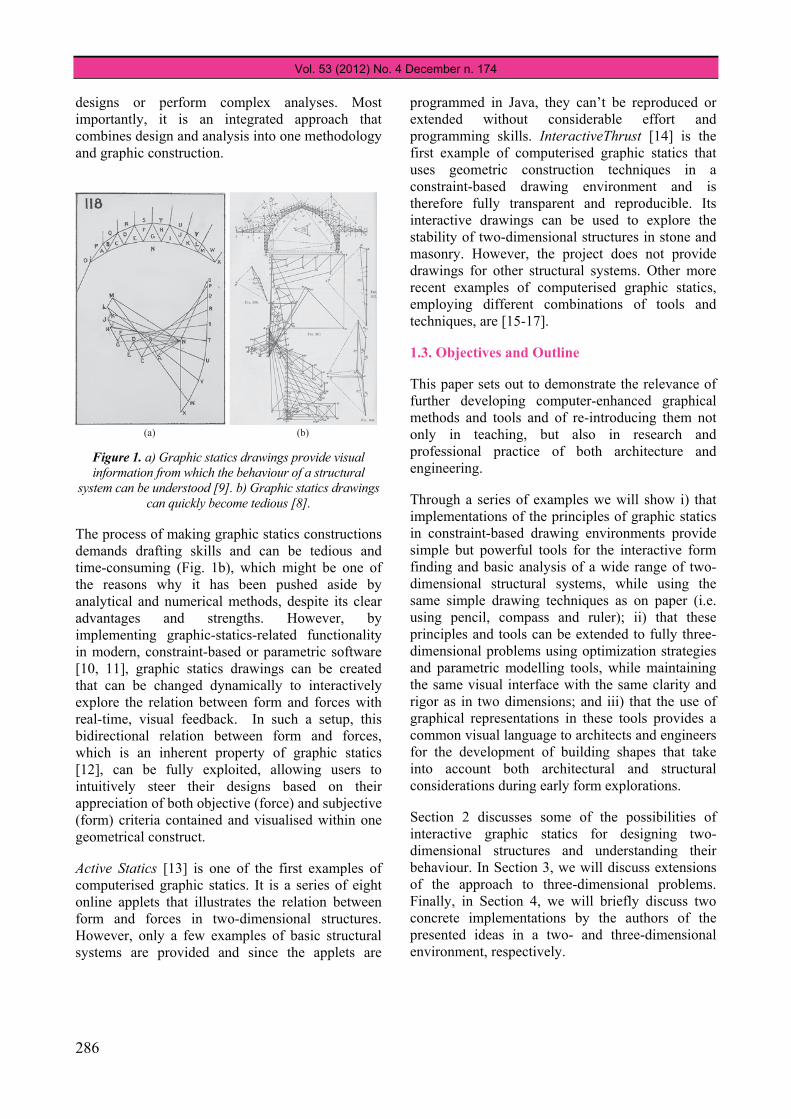
Figure 1. a) Graphic statics drawings provide visual information from which the behaviour of a structural
system can be understood [9]. b) Graphic statics drawings can quickly become tedious [8].
The process of making graphic statics constructions demands drafting skills and can be tedious and time-consuming (Fig. 1b), which might be one of the reasons why it has been pushed aside by analytical and numerical methods, despite its clear advantages and strengths. However, by implementing graphic-statics-related functionality in modern, constraint-based or parametric software [10, 11], graphic statics drawings can be created that can be changed dynamically to interactively explore the relation between form and forces with real-time, visual feedback. In such a setup, this bidirectional relation between form and forces, which is an inherent property of graphic statics [12], can be fully exploited, allowing users to intuitively steer their designs based on their appreciation of both objective (force) and subjective (form) criteria contained and visualised within one geometrical construct.
Active Statics [13] is one of the first examples of computerised graphic statics. It is a series of eight online applets that illustrates the relation between form and forces in two-dimensional structures. However, only a few examples of basic structural systems are provided and since the applets are
programmed in Java, they can’t be reproduced or extended without considerable effort and programming skills. InteractiveThrust [14] is the first example of computerised graphic statics that uses geometric construction techniques in a constraint-based drawing environment and is therefore fully transparent and reproducible. Its interactive drawings can be used to explore the stability of two-dimensional structures in stone and masonry. However, the project does not provide drawings for other structural systems. Other more recent examples of computerised graphic statics, employing different combinations of tools and techniques, are [15-17].
1.3. Objectives and Outline
This paper sets out to demonstrate the relevance of further developing computer-enhanced graphical methods and tools and of re-introducing them not only in teaching, but also in research and professional practice of both architecture and engineering.
Through a series of examples we will show i) that implementations of the principles of graphic statics in constraint-based drawing environments provide simple but powerful tools for the interactive form finding and basic analysis of a wide range of two-dimensional structural systems, while using the same simple drawing techniques as on paper (i.e. using pencil, compass and ruler); ii) that these principles and tools can be extended to fully three-dimensional problems using optimization strategies and parametric modelling tools, while maintaining the same visual interface with the same clarity and rigor as in two dimensions; and iii) that the use of graphical representations in these tools provides a common visual language to architects and engineers for the development of building shapes that take into account both architectural and structural considerations during early form explorations.
Section 2 discusses some of the possibilities of interactive graphic statics for designing two-dimensional structures and understanding their behaviour. In Section 3, we will discuss extensions of the approach to three-dimensional problems. Finally, in Section 4, we will briefly discuss two concrete implementations by the authors of the presented ideas in a two- and three-dimensional environment, respectively.
(a) (b)

JOURNAL OF THE INTERNATIONAL ASSOCIATION FOR SHELL AND SPATIAL STRUCTURES: J. IASS
287
2. INTERACTIVE, GRAPHIC-STATICS-BASED DESIGN OF 2D STRUCTURES
In the following examples we will show how interactive graphic statics can be used to design efficient truss structures by imposing geometrical constraints to the force diagram; design bending-free, freeform arches using the information provided by the funicular line; and understand and explain indeterminacy and the stability of masonry arches.
2.1. Trusses with Constant-force Chords
Consider the problem of designing a truss with a constant-force bottom chord for a given set of loads applied to a top chord with given geometry. For clarity, the applied loads are all taken vertical, equal and evenly spaced along the top chord. However, this is not a limitation.
Figure 2 shows the form (left) and force (right) diagrams of this structural system for a straight top chord [4]. These diagrams can be read as follows: the lengths of the segments in the force diagram represent the magnitude of the forces in the corresponding elements in the form diagram. Using Bow's notation [9], labelling spaces in the form diagram and nodes in the force diagram with the nodes in the latter corresponding to the spaces in the former, the elements of the truss in the force diagram can be named and grouped in the following categories:
• magnitudes of the applied loads: a-b, b-c, c-d, d-e, e-f
• forces in the members of the top chord: a-1, b-2, c-3, d-4, e-5, f-6
• forces in the members of the bottom chord: g-1, g-2, g-3, g-4, g-5, g-6
• forces in the connecting struts: 1-2, 2-3, 3-4, 4-5, 5-6
The dashed solution in Figure 2 has a constant force in the top chord, as can be seen from the equal lengths of the corresponding segments in the force diagram. The solution with continuous lines has a constant force in its bottom chord; all elements in the force diagram corresponding to the bottom
Figure 2. Graphic statics solutions to the problem of
designing a truss with constant-force chords: constant-force top chord (dashed lines), and constant-force bottom
chord (continuous lines). [4]
Figure 3. Implementation of the constant-force bottom
chord principle in an interactive drawing on eQUILIBRIUM [18]. Control over the shape of the top chord in combination with the force constraint on the bottom chord allows for an exploration of freeform
constant force trusses.
chord have the same length, which is obtained by constraining points 1 to 6 to a circle with centre at g and radius corresponding to the desired (constant) magnitude of force in the chord. This geometric constraint on the force diagram results in non-vertical struts in the solution, and their required orientation can be derived directly from the force diagram.
A B C D E F
G
a
b
c
g
d
e
f
1
2
3
4
5
6
1 62 5
3 4
Vol. 53 (2012) No. 4 December n. 174
288
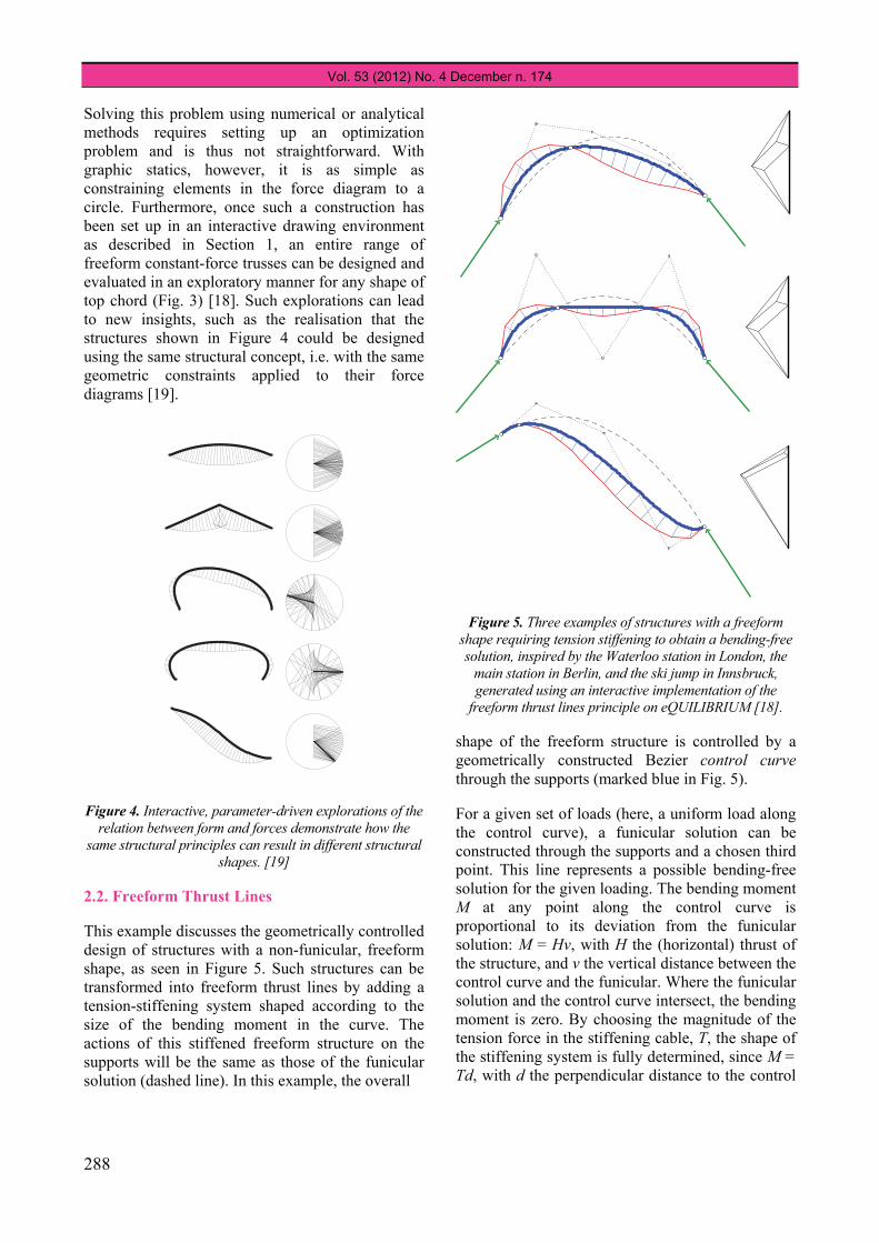
Solving this problem using numerical or analytical methods requires setting up an optimization problem and is thus not straightforward. With graphic statics, however, it is as simple as constraining elements in the force diagram to a circle. Furthermore, once such a construction has been set up in an interactive drawing environment as described in Section 1, an entire range of freeform constant-force trusses can be designed and evaluated in an exploratory manner for any shape of top chord (Fig. 3) [18]. Such explorations can lead to new insights, such as the realisation that the structures shown in Figure 4 could be designed using the same structural concept, i.e. with the same geometric constraints applied to their force diagrams [19].
Figure 4. Interactive, parameter-driven explorations of the relation between form and forces demonstrate how the
same structural principles can result in different structural shapes. [19]
2.2. Freeform Thrust Lines
This example discusses the geometrically controlled design of structures with a non-funicular, freeform shape, as seen in Figure 5. Such structures can be transformed into freeform thrust lines by adding a tension-stiffening system shaped according to the size of the bending moment in the curve. The actions of this stiffened freeform structure on the supports will be the same as those of the funicular solution (dashed line). In this example, the overall
Figure 5. Three examples of structures with a freeform shape requiring tension stiffening to obtain a bending-free solution, inspired by the Waterloo station in London, the
main station in Berlin, and the ski jump in Innsbruck, generated using an interactive implementation of the
freeform thrust lines principle on eQUILIBRIUM [18].
shape of the freeform structure is controlled by a geometrically constructed Bezier control curve through the supports (marked blue in Fig. 5).
For a given set of loads (here, a uniform load along the control curve), a funicular solution can be constructed through the supports and a chosen third point. This line represents a possible bending-free solution for the given loading. The bending moment M at any point along the control curve is proportional to its deviation from the funicular solution: M = Hv, with H the (horizontal) thrust of the structure, and v the vertical distance between the control curve and the funicular. Where the funicular solution and the control curve intersect, the bending moment is zero. By choosing the magnitude of the tension force in the stiffening cable, T, the shape of the stiffening system is fully determined, since M = Td, with d the perpendicular distance to the control

JOURNAL OF THE INTERNATIONAL ASSOCIATION FOR SHELL AND SPATIAL STRUCTURES: J. IASS
289
curve. This system transforms the control curve into a thrust line with the desired freeform shape.
In an interactive environment [18], different configurations of this complex structural system can thus be explored and accurately designed without any calculations, simply by determining the overall shape of the structure using the control points of the Bezier curve, by choosing the shape of the funicular through the location of the zero-bending-point, and by choosing the desired size of the cable force in the stiffening system.
2.4. Static Indeterminacy
The problem shown in Figure 6 can be used in the classroom to explain the concept of static indeterminacy. It also demonstrates that graphic analysis methods are not limited to statically determinate structures and can be used to illustrate the possible equilibrium solutions of (externally) hyperstatic structures [20, 21].
A possible way to approach the problem of determining the stress state of an indeterminate system is to accept that in reality the boundary conditions will never be perfect and that therefore the actual internal stress state of the system is unknown. This can be shown easily with this three-bar system.
Figure 6. An indeterminate three-bar structure with one applied load can have several stress states depending on
the boundary conditions. (a) is the elastic solution.
Figure 6a depicts the elastic solution for bars with the same axial stiffness EA. This is the answer that would be obtained with a linear elastic analysis as the definite solution to this problem. However, if for example the bar segment BC is slightly longer than intended or the middle support has slightly moved downwards compared to its intended location, the tension forces in AB and CD will be higher (Fig. 6b). Similarly, a shorter BC or higher middle support will reduce the tension forces in AB
and CD, and, from a certain point, even cause AB and CD to go in compression (Fig. 6c).
Minimal changes from the idealized situation can cause huge shifts in internal stresses in hyperstatic structures. Unlike analytical or numerical calculation, the force diagram of the graphic statics construction visualizes all possible states of stress (Fig. 6d), and using an interactive implementation, an advanced and often poorly understood structural issue can be explained and explored in a visual and understandable manner.
2.5. Stability of Masonry
Thrust line analysis is a well-known method for the equilibrium analysis (and design) of rigid block assemblies such as masonry structures [22].
In the theoretical “perfect world” situation of the voussoir arch with perfect geometry and homogenous material that fits perfectly between its infinitely rigid foundations, an infinite number of possible states of stress exist. Every state of stress can be represented by a line of thrust contained within the arch. Two extreme situations exist, corresponding to a minimum and maximum thrust at the supports, represented by the deepest and shallowest line in Figure 7.
In the real world however, displacements of the supports will occur (e.g. immediately after decentring) and cause the arch to crack, effectively developing hinges around which parts of the arch can rotate to compensate for the slight increase or decrease in span [22, 23]. Those hinges develop where the possible lines of thrust touch the boundaries of the arch geometry [22]. If the thrust in the arch pushes the foundations outwards, possible crack and hinge locations are determined by the line of minimum thrust. In the opposite case where the arch foundations are pushed inwards by the surroundings (e.g. as the result of a larger thrust in a neighbouring arch), the crack and hinge locations will be determined by the line of maximum thrust. From the moment the arch cracks, the locations of the hinges determine a unique line of thrust and consequently a unique state of stress for the arch. Further movements of the supports will cause the arch to collapse once a line of thrust that is entirely contained within the geometry of the arch can no longer be found; i.e. once an unstable mechanism is formed by the creation of an additional hinge (Fig. 8).
A A A
B B’ B”C C’ C”D D D
PPPP
cd-line
ab-line
a
d
c
c’
c”
b”
b’
bF = 0.52 * PF = 0.36 * PF = 0.23 * P
-l
-l
-
BC
CD
DA
F = 0.69 * PF = .27 * PF = 0.81 * P
-1
l
-l
-
BC
CD
DA
F = .83 * PF = 0.77 * PF = .40 * P
-l
l
2--0
BC
CD
DA
(a) (b) (d)( )vc

Vol. 53 (2012) No. 4 December n. 174
290
Figure 7. Lines of minimum (deep) and maximum (shallow) thrust of an arch. Possible hinge locations are there where these limit thrust lines touch the boundary of
the arch geometry.
Figure 8. An arch on spreading supports has an internal state of stress represented by the line of minimum thrust.
The arch is stable as long as this thrust line is fully contained within the boundaries of the arch. [24]
Note that the complete analysis of the structural integrity of a masonry structure also involves other aspects such as the evaluation of stresses. However, a satisfactory stability analysis is a necessary and required condition for the arch to stand, even when the stresses are well within the allowable bounds [21,22]. The advantage of a graphic-statics-based approach to this stability analysis, as shown here for the self-weight of the arch, is that it allows for the integrated and thus simultaneous evaluation of the structural and kinematical aspects of the problem in a visual and understandable manner [24].
3. INTERACTIVE, GRAPHIC STATICS-BASED FORM FINDING OF 3D STRUCTURES
Although fully three-dimensional graphic statics is possible (see for example [25]), practical applications are extremely complicated and tedious. Therefore in the past, three-dimensional structural systems have been handled by reducing them to a combination of two-dimensional problems, for
example as in [8, 24]. However, by separating horizontal and vertical equilibrium, and under the condition of vertical loading (or, more general, parallel loading), the principles of graphic statics can be applied to three-dimensional surface structures as well. It is beyond the scope of this paper to explain this in detail, but we will summarize the most important principles behind the approach.
Figure 9. Four four-bar structures Gi with the same fixed horizontal projection GH and associated form
diagram Γ are in equilibrium with the same load applied at their central node. Their respective horizontal force equilibriums are given by the
reciprocal force diagrams Γ*i or the polyhedral
Airy stress functions Ĝi, representing 1) a compression-only, 2) a tension-only (hanging), 3) a tension-only (pre-stressed), and 4) a mixed tension-
compression equilibrium solution.
Consider a three-dimensional network G of bars and nodes that is in equilibrium with a set of loads applied to its nodes. The horizontal projection GH of this network can be seen as a form diagram for which a force diagram exists that describes its in-plane equilibrium; and since the vertical loads on G do not appear in the horizontal projection (i.e. the form diagram), the force diagram also describes the horizontal equilibrium of the three-dimensional
1
22
4
35
1 2
4 3
G1
G2
G3
G4
GH
G1
G2
G3
G4
GHΓ
Γ4∗
Γ3∗
Γ2∗
Γ1∗ 1
23
4
3
41
2
3
41
2
2
14
3
JOURNAL OF THE INTERNATIONAL ASSOCIATION FOR SHELL AND SPATIAL STRUCTURES: J. IASS
291
network G [26]. Therefore for a given form diagram and boundary conditions, each force diagram corresponds to a three-dimensional network in equilibrium with the given loads that is uniquely defined up to a scale factor and has the form diagram as its horizontal projection.
As an illustration of this concept, Figure 9 depicts four four-bar, pin-jointed networks G1, G2, G3 and G4 with the same horizontal projection GH and the same vertical load applied to their central node. The force diagrams Γ*
1, Γ*2, Γ*
3 and Γ*4 represent four
different states of in-plane equilibrium of the form diagram Γ, corresponding to a compression-only network (G1), a tension-only hanging network (G2), a tension-only pre-stressed network (G3) and a mixed tension-compression network (G4), respectively. Figure 9 furthermore shows the equivalent polyhedral Airy stress functions [27] for the four networks, which are particularly useful as alternative control mechanisms in the case of mixed compression-tension structures as we will see in Section 3.3.
This example shows that the infinite possible shapes of equilibrium of a network G for a given set of vertical loads and boundary conditions can be explored using the statically indeterminate, planar form diagram corresponding to the horizontal projection of G and the force diagram representing its different states of horizontal equilibrium.
This approach can, for example, be used for the initial form finding of structures for which self-weight is the dominant loading. Note that other load cases than the vertical case may also be considered, as long as the loads are parallel and the projection of G is taken on a plane perpendicular to the direction of the loads.
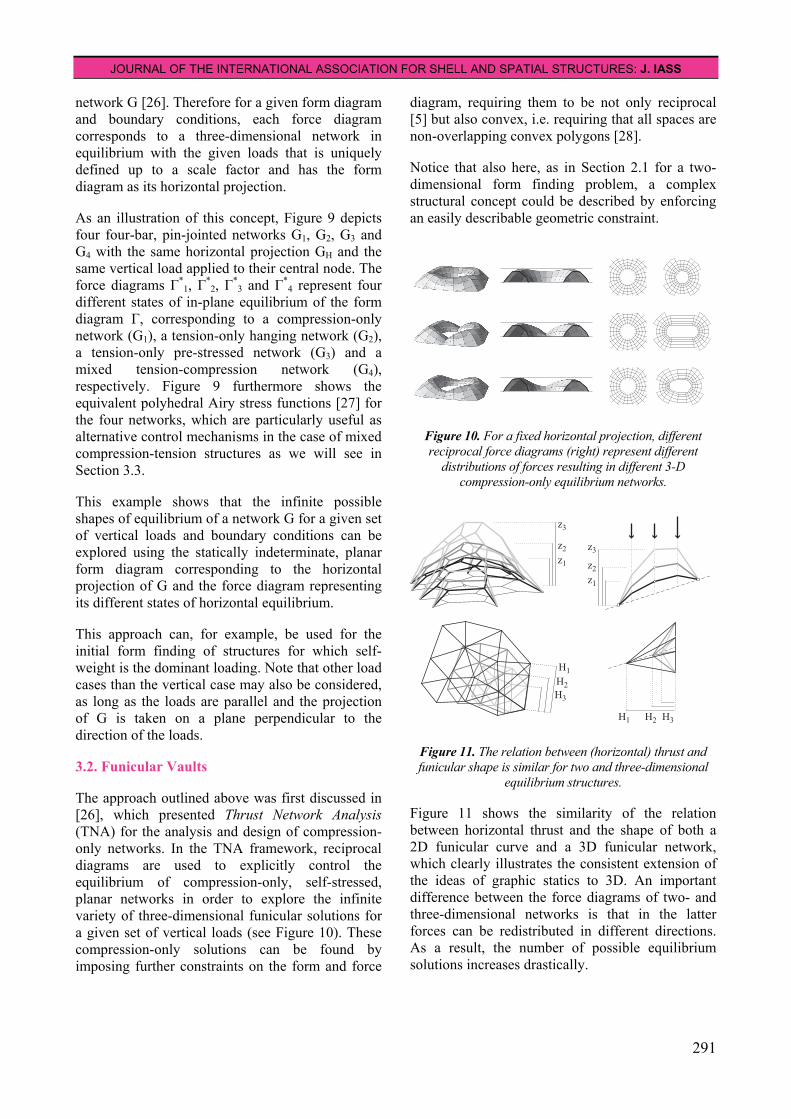
3.2. Funicular Vaults
The approach outlined above was first discussed in [26], which presented Thrust Network Analysis (TNA) for the analysis and design of compression-only networks. In the TNA framework, reciprocal diagrams are used to explicitly control the equilibrium of compression-only, self-stressed, planar networks in order to explore the infinite variety of three-dimensional funicular solutions for a given set of vertical loads (see Figure 10). These compression-only solutions can be found by imposing further constraints on the form and force
diagram, requiring them to be not only reciprocal [5] but also convex, i.e. requiring that all spaces are non-overlapping convex polygons [28].
Notice that also here, as in Section 2.1 for a two-dimensional form finding problem, a complex structural concept could be described by enforcing an easily describable geometric constraint.
Figure 10. For a fixed horizontal projection, different reciprocal force diagrams (right) represent different
distributions of forces resulting in different 3-D compression-only equilibrium networks.
Figure 11. The relation between (horizontal) thrust and funicular shape is similar for two and three-dimensional
equilibrium structures.
Figure 11 shows the similarity of the relation between horizontal thrust and the shape of both a 2D funicular curve and a 3D funicular network, which clearly illustrates the consistent extension of the ideas of graphic statics to 3D. An important difference between the force diagrams of two- and three-dimensional networks is that in the latter forces can be redistributed in different directions. As a result, the number of possible equilibrium solutions increases drastically.
z1z2
z3
z1z2
z3
H3H2H1
H1H2H3

Vol. 53 (2012) No. 4 December n. 174
292
3.3. Hybrid Compression-Tension Shells
It follows from the previous section that by simply removing the convexity constraint on the force diagram that limits the possible equilibrium networks to compression-only solutions, the TNA framework could also be used to design three-dimensional networks in which both tension and compression occur.
Figure 12 shows different equilibrium states for a fixed form diagram. Force diagrams (a) and (b) represent the horizontal equilibrium of compression-only solutions; all spaces in the diagrams are convex and do not overlap. In force diagram (c), however, the spaces overlap because both tension and compression occur. For combined compression-tension solutions the reciprocal force diagrams can thus quickly become illegible. As a result, controlling the forces in such structures using force diagrams becomes unmanageable.
Figure 12. The reciprocal force diagrams (top) and polyhedral Airy stress function (middle) of three
equilibrium solutions (bottom) with the same horizontal projection. a) and b) represent compression-only solutions
and c) a combined compression-tension solution.
By using polyhedral Airy stress functions [27], which are equivalent representations of reciprocal diagrams [28, 30] that do not contain overlaps when tension and compression are mixed, interesting hybrid structures can be generated without loss of legibility of the force diagram and hence control over the equilibrium (Fig. 12c). The stresses in the branches of the equilibrium networks are proportional to the dihedral angles between the
faces adjacent to the corresponding branches in the polyhedral stress function. Concave and convex angles represent either tension or compression, depending on the conventions [31].
Figure 12 hints at the form finding possibilities of an extension of the TNA framework with Airy stress functions, and illustrates again that control over a complex structural system and behaviour is obtained through a geometrical representation and constrained (flat faces) construct.
4. IMPLEMENTATIONS
The authors have developed interactive applications for both two- and three-dimensional shaping of structures. These applications were used to generate the examples in Sections 2 and 3.
4.1. eQUILIBRIUM
The examples in Section 2 were created with an interactive implementation of graphic statics in GeoGebra [10]. The interactive drawings can be found on eQUILIBRIUM, which is an interactive, web-based learning platform for structural design, used for the introductory structures classes in architecture at ETH Zurich [18].
All drawings are produced without calculations, using only geometric construction techniques, as they would be on paper using pencil, compass and ruler. To increase the readability of the models, the constructions are extended with automatic detection of compression and tension. This is done based on the interpretation of form and force diagram, as explained in [8].
4.2. RhinoVAULT
The examples in Section 3 were produced using RhinoVAULT [32], which is a plug-in for Rhinoceros [33] for form finding of compression-only vaults using the TNA framework [34]. Figure 13 shows a design exploration of a compression-only vault with RhinoVAULT. Figure 13d shows the prototype unreinforced masonry vault designed with RhinoVAULT and built at ETH Zurich [35].
It is important in the context of this paper to emphasize that the solving algorithms which allow for the weighted bidirectional implementation of RhinoVAULT were only possible because indeed the relation between force equilibrium and three-
(a) (b) (c)

JOURNAL OF THE INTERNATIONAL ASSOCIATION FOR SHELL AND SPATIAL STRUCTURES: J. IASS
293
dimensional form are explicitly represented by the geometrically linked form and force diagram.
5. CONCLUSIONS
This paper presented the possibilities of using a geometry-based approach to structural form finding that adopts the key principles of graphic statics and extends them to fully three-dimensional problems using structural design and optimisation techniques.
It has been shown that implementations of the resulting methods in modern drawing and modelling software (and in some cases in web-based environments) can be used to create tools for two- and three-dimensional equilibrium design and basic analysis that provide control over the complex relation between the geometry of structures and the forces in them.
Although these tools cannot be used for the complete design and analysis of a building, they are extremely useful during early form finding stages for structurally informed shape explorations that can result in the development of architectural forms that are typically not associated with equilibrium structures. The results of these explorations then provide good starting points for further development.
Furthermore, because of the combined simplicity, readability and power of the graphical representation of form and forces, we argue that these tools are useful not only in teaching, but also in research and practice of both architecture and engineering.
REFERENCES
[1] Oxman R. and Oxman R., The New Structuralism: Design, Engineering and Architectural Technologies, Architectural Design, John Wiley, London, 2010.
[2] Pottmann H., Liu Y., Wallner J., Bobenko A. and Wang W., Geometry of multi-layer freeform structures for architecture, ACM Trans. Graphics, 26/3, Proc. SIGGRAPH. 2007.
[3] Sasaki M., Morphogenesis of Flux Structure, AA Publications, London, 2007.
Figure 13. Overview of TNA-based design process of a
funicular compression-only vault with RhinoVAULT [24]: a) starting geometry, b) integration of open edges, c) final
solution after re-distribution of internal forces.
a
b
c

Vol. 53 (2012) No. 4 December n. 174
294
[4] Allen E. and Zalewski W., Form and Forces: Designing Efficient, Expressive Structures, John Wiley & Sons, New York, 2009.
[5] Maxwell J.C., On Reciprocal Figures and Diagrams of Forces, Philosophical Magazine and Journal Series, Vol. 4, No. 27, 1864, pp. 250-261.
[6] Culmann C., Die graphische Statik, Verlag von Meyer & Zeller, Zurich, 1864/1866.
[7] Cremona L., Le Figure Reciproche nella Statica Graphica, Ulrico Hoepli, Milano, 1879.
[8] Wolfe W.S., Graphical Analysis: A handbook on graphic Statics, McGraw-Hill Book Company, New York, 1921.
[9] Bow R.H., Economics of construction in relation to framed structures, Spon, London, 1873.
[10] Hohenwarter M., GeoGebra, www.geogebra.org
[11] Rutten D., Grasshopper, www.grasshopper3d.com
[12] Kilian, A. Design Exploration through Bidirectional Modelling of Constraints, PhD dissertation, Massachusetts Institute of Technology, Cambridge, USA, 2006.
[13] Greenwold S., Active Statics, acg.media.mit.edu/people/simong/statics
[14] Block P., InteractiveThrust, web.mit.edu/masonry/interactiveThrust
[15] Shearer M., Analyzing and Creating Forms: Rapid Generation of Graphic Statics Solutions Through RhinoScript, Master Thesis, Massachusetts Institute of Technology, Cambridge, USA, 2010.
[16] Lachauer L., Jungjohann H. and Kotnik T., Interactive Parametric Tools for Structural Design, Proceedings of the International Association for Shell and Spatial Structures (IABSE-IASS) Symposium, London, 2011.
[17] Fivet C., Zastavni D., Cap J., Extending Graphic Statics for User-Controlled Structural Morphogenesis, Proceedings of the SMG workshop at the IABSE-IASS Symposium, London, 2011
[18] Van Mele T. and Block P., eQUILIBRIUM, block.arch.ethz.ch/equilibrium
[19] Lachauer L. and Kotnik T., Geometry of Structural Form, Advances of Architectural Geometry 2010, Vienna, Austria, 2010, pp. 193-203.
[20] Kilian A. and Ochsendorf J., Particle-spring systems for structural form finding, Journal of the IASS, Vol. 46, No. 2, 2005, pp. 77-85.
[21] Block P. and Ochsendorf J., Interactive thrust line analysis for masonry structures. Theory and Practice of Construction: Knowledge, Means, and Models, Ravenna, Italy, 2005, pp. 473-483.
[22] Heyman, J., The Stone Skeleton: Structural engineering of masonry architecture, Cambridge University Press, 1995.
[23] Ochsendorf J.A., The Masonry Arch on Spreading Supports, The Structural Engineer, Vol. 84, No. 2, 2006, pp. 29-36.
[24] Block P., Ciblac T. and Ochsendorf J.A., Real-time limit analysis of vaulted masonry buildings, Computers & Structures, Vol. 84, No. 29-30, 2006, pp. 1841-1852.
[25] Föppl, A., Das Fachwerk im Raume, Verlag von B.G. Teubner, Leipzig, 1892.
[26] Block P. and Ochsendorf J., Thrust Network Analysis: A new methodology for three-dimensional equilibrium, Journal of the IASS, Vol. 48, No. 3, 2007, pp. 167-173.
[27] Maxwell, J.C., On reciprocal diagrams in space and their relation to Airy's function of stress, Proceedings of London Mathematical Society, Vol. 2, 1869, pp. 58-60.
JOURNAL OF THE INTERNATIONAL ASSOCIATION FOR SHELL AND SPATIAL STRUCTURES: J. IASS
295
[28] Block P., Thrust Network Analysis: Exploring Three-dimensional Equilibrium, PhD dissertation, Massachusetts Institute of Technology, Cambridge, USA, 2009.
[29] Williams C.J.K., The generation of a class of structural forms for vaults and sails, The Structural Engineer, Vol. 68, No. 12, 1990, pp. 231-235.
[30] Fraternali F., A thrust network approach to the equilibrium problem of unreinforced masonry vaults via polyhedral stress functions, Mechanics Research Comm., Vol. 37, 2010, pp. 198-204.
[31] Crapo H. and Whiteley W., Plane self-stresses and projected polyhedral I: The basic
pattern, Structural Topology, Vol. 20, 1993, pp. 55-78.
[32] Rippmann M., Lachauer L. and Block P., RhinoVAULT, http://block.arch.ethz.ch/tools
[33] McNeel B., Rhino, http://www.rhino3d.com
[34] Rippmann M., Lachauer L. and Block, P., Interactive Vault Design, International Journal of Space Structures, Vol. 27, Nr. 4, 2012, pp. 219-230.
[35] Davis L., Rippmann M., Pawlofsky T. and Block P., Innovative Funicular Tile Vaulting: A prototype in Switzerland, The Structural Engineer, Vol. 90, Nr. 11, 2012, pp. 46-56.


![Symmetry, Integrability and Geometry: Methods and ... · on M associated to an open cone of the fan for M, ˇ B has the form (1.2) where [B pq] is the matrix representing Bwith respect](https://static.fdocuments.in/doc/165x107/5f64fda0fde6d46f6d210f96/symmetry-integrability-and-geometry-methods-and-on-m-associated-to-an-open.jpg)


