Geometry and kinematic evolution of Riedel shear structures ...
11
Geometry and kinematic evolution of Riedel shear structures, Capitol Reef National Park, Utah Yoram Katz a,b, * , Ram Weinberger b , Atilla Aydin c a Institute of Earth Sciences, Hebrew University of Jerusalem, Jerusalem 95501, Israel b Geological Survey of Israel, Jerusalem, Israel c Department of Geological and Environmental Sciences, Stanford University, Stanford, CA, USA Received 27 November 2002 Abstract Riedel shear structures are common fault patterns identified within shear zones and related to the embryonic stages of fault formation. This study focuses on the geometry of outcrop-scale natural shear zones consisting of different generations of Riedel structures, exposed in the Jurassic Navajo sandstone, Capitol Reef National Park, Utah. Geometric analysis of different structures shows that the spacing of synthetic R- deformation bands increases with the spacing of antithetic R 0 -deformation bands. Systematic correlation is found between the R-band spacing and the angles formed between R- and R 0 -bands. Examination of young Riedel structures shows their tendency to localize along narrow, elongated domains sub-parallel to the shear direction and create denser Riedel networks. We suggest that the evolution of Riedel structures is dominated by two mechanisms: (1) discrete faulting in the form of conjugate deformation bands, generally complying with the Mohr – Coulomb criteria, and (2) granular flow, which rotates mainly the R 0 -deformation bands. Both mechanisms are intensified with progressive strain, decreasing the deformation-band spacing and increasing the R- to R 0 -angles. The tendency of young Riedel structures to organize in dense elongated networks is related to strain localization during the shear-zone evolution. We suggest a kinematic explanation for the evolution of Riedel-structure networks, which relates the network geometry to the progressive accumulation and localization of shear strain. q 2003 Elsevier Ltd. All rights reserved. Keywords: Deformation bands; Riedel structures; Strain localization; Shear zones 1. Introduction Riedel structures are networks of shear bands, commonly developed in zones of simple shear during the early stages of faulting. The basic geometry of the Riedel structure consists of conjugate shear bands arranged in en-e ´chelon arrays and denoted by R and R 0 (Fig. 1). The R- and R 0 -bands create an angle of about f/2 and 90 2 f/2 to the general shear-zone direction, respectively, and intersect in an acute angle of b ¼ 90 2 f, where f is the angle of internal friction (Riedel, 1929; Tchalenko, 1968). The R-bands are synthetic to the sense of slip across the shear-zone, forming right- stepping en-e ´chelon arrays along sinistral shear-zones and left-stepping arrays along dextral shear-zones. The R 0 -bands are antithetic, and usually connect overlapping R-bands. The Riedel shear structure, first reported by Cloos (1928) and Riedel (1929) in clay-cake experiments, was realized to be a fundamental structure within shear-zones. Studies of macro-scale fault systems have associated these structures with strike-slip displacement induced by earthquakes (Tchalenko, 1970), basement faulting (Moore, 1979) and interplate shearing (Cunningham, 1993). Studies in meso- scale (e.g. Jamison and Stearns, 1982; Antonellini and Aydin, 1995; Davis et al., 1999; Ortlepp, 2000; Ahlgren, 2001), micro-scale (e.g. Jamison and Stearns, 1982; Arboleya and Engelder, 1995) and laboratory experiments (e.g. Tchalenko, 1970; Naylor et al., 1986) documented Riedel structures of various sizes within different rock types and geologic settings. The present study focuses on the geometrical character- ization and time relationship between Riedel shear struc- tures within the Jurassic Navajo sandstone in Capitol Reef National Park, Utah (Fig. 2). The cataclastic shear bands 0191-8141/$ - see front matter q 2003 Elsevier Ltd. All rights reserved. doi:10.1016/j.jsg.2003.08.003 Journal of Structural Geology 26 (2004) 491–501 www.elsevier.com/locate/jsg * Corresponding author. Tel.: þ 972-2-5314211; fax: þ 972-2-5380688. E-mail address: [email protected] (Y. Katz).
Transcript of Geometry and kinematic evolution of Riedel shear structures ...
Geometry and kinematic evolution of Riedel shear structures,
Capitol Reef National Park, Utah
Yoram Katza,b,*, Ram Weinbergerb, Atilla Aydinc
aInstitute of Earth Sciences, Hebrew University of Jerusalem, Jerusalem 95501, IsraelbGeological Survey of Israel, Jerusalem, Israel
cDepartment of Geological and Environmental Sciences, Stanford University, Stanford, CA, USA
Received 27 November 2002
Abstract
Riedel shear structures are common fault patterns identified within shear zones and related to the embryonic stages of fault formation. This
study focuses on the geometry of outcrop-scale natural shear zones consisting of different generations of Riedel structures, exposed in the
Jurassic Navajo sandstone, Capitol Reef National Park, Utah. Geometric analysis of different structures shows that the spacing of synthetic R-
deformation bands increases with the spacing of antithetic R0-deformation bands. Systematic correlation is found between the R-band
spacing and the angles formed between R- and R0-bands. Examination of young Riedel structures shows their tendency to localize along
narrow, elongated domains sub-parallel to the shear direction and create denser Riedel networks. We suggest that the evolution of Riedel
structures is dominated by two mechanisms: (1) discrete faulting in the form of conjugate deformation bands, generally complying with the
Mohr–Coulomb criteria, and (2) granular flow, which rotates mainly the R0-deformation bands. Both mechanisms are intensified with
progressive strain, decreasing the deformation-band spacing and increasing the R- to R0-angles. The tendency of young Riedel structures to
organize in dense elongated networks is related to strain localization during the shear-zone evolution. We suggest a kinematic explanation for
the evolution of Riedel-structure networks, which relates the network geometry to the progressive accumulation and localization of shear
strain.
q 2003 Elsevier Ltd. All rights reserved.
Keywords: Deformation bands; Riedel structures; Strain localization; Shear zones
1. Introduction
Riedel structures are networks of shear bands, commonly
developed in zones of simple shear during the early stages of
faulting. The basic geometry of the Riedel structure consists
of conjugate shear bands arranged in en-echelon arrays and
denoted by R and R0 (Fig. 1). The R- and R0-bands create an
angle of about f/2 and 90 2 f/2 to the general shear-zone
direction, respectively, and intersect in an acute angle of
b ¼ 90 2 f, where f is the angle of internal friction
(Riedel, 1929; Tchalenko, 1968). The R-bands are synthetic
to the sense of slip across the shear-zone, forming right-
stepping en-echelon arrays along sinistral shear-zones and
left-stepping arrays along dextral shear-zones. The R0-bands
are antithetic, and usually connect overlapping R-bands.
The Riedel shear structure, first reported by Cloos (1928)
and Riedel (1929) in clay-cake experiments, was realized to
be a fundamental structure within shear-zones. Studies of
macro-scale fault systems have associated these structures
with strike-slip displacement induced by earthquakes
(Tchalenko, 1970), basement faulting (Moore, 1979) and
interplate shearing (Cunningham, 1993). Studies in meso-
scale (e.g. Jamison and Stearns, 1982; Antonellini and
Aydin, 1995; Davis et al., 1999; Ortlepp, 2000; Ahlgren,
2001), micro-scale (e.g. Jamison and Stearns, 1982;
Arboleya and Engelder, 1995) and laboratory experiments
(e.g. Tchalenko, 1970; Naylor et al., 1986) documented
Riedel structures of various sizes within different rock types
and geologic settings.
The present study focuses on the geometrical character-
ization and time relationship between Riedel shear struc-
tures within the Jurassic Navajo sandstone in Capitol Reef
National Park, Utah (Fig. 2). The cataclastic shear bands
0191-8141/$ - see front matter q 2003 Elsevier Ltd. All rights reserved.
doi:10.1016/j.jsg.2003.08.003
Journal of Structural Geology 26 (2004) 491–501
www.elsevier.com/locate/jsg
* Corresponding author. Tel.: þ972-2-5314211; fax: þ972-2-5380688.
E-mail address: [email protected] (Y. Katz).

forming Riedel structures in sandstone, commonly termed
deformation bands, are typically ,1 mm in width and may
have offsets of several millimeters. Their formation is
associated with collapse of pore space, breakage and
crushing of grains, and a major reduction of porosity and
permeability (Aydin, 1978; Aydin and Johnson, 1978;
Antonellini and Aydin, 1994). Analysis of dozens of
discrete and nested Riedel structures has shown systematic
correlation between the geometry, the distribution and the
relative age of the structures. This correlation may have
significant implications with regard to the prediction of
shear zone architecture during accumulation of strain.
Moreover, knowing the average permeability of a single
deformation band and once the shear zone architecture is
well defined, hydrological variables of the fault zone, as
conductivity tensor, bulk porosity and tortuosity can be
evaluated. Motivated by the major structural and hydro-
logical significance, this study suggests a kinematic model
for the development of Riedel-structure networks and
correlates them with progressive deformation within shear
zones.
2. Geological setting
The study area is located along the Waterpocket
monocline in Capitol Reef National Park, where Riedel
shear structures are well exposed within outcrops of the
Jurassic Navajo sandstone. Data was collected at the
northern bank of Capitol Wash, which crosses the mono-
cline from west to east, 6 km south of the Fremont River
(Fig. 2). The NW–N-trending monocline is believed to have
initiated at ,75 Ma and to have ceased activity prior to the
Eocene (Baker, 1935; Kelley, 1955; Dumitru et al., 1994).
The Navajo Formation consists of porous, quartz-rich
sandstone and exhibits whitish, cross-bedded massive
outcrops (Kiersch, 1950; Marzolf, 1983, 1990; Antonellini
and Aydin, 1994). It is underlain by shales and sandstones of
the Jurassic Glen–Canyon Group and overlain by shales and
sandstones of the Jurassic San Rafael Group.
Being readily deformable, the Navajo Formation exhibits
various internal deformation features (e.g. Shipton and
Cowie, 2001; Davatzes et al., 2003). Davis (1999) and Davis
et al. (1999) carried out a structural analysis of deformation
band shear-zones in south-central Utah, including the north-
central and southern parts of the Waterpocket monocline. In
the Sheets Gulch area, located approximately 16 km south
of the present study area, strike-slip shear-zones consisting
of Riedel structures were reported to occur in two conjugate
sets, a dextral set striking NE, and a sinistral set striking
ESE, both showing high dip angles of ,758. Davis et al.
(1999) suggested that the conjugate sets accommodated
strain during the Laramide regional shortening perpendicu-
lar to the Waterpocket monocline hinge, and Roznovsky and
Aydin (2001) proposed that major Riedel-structure net-
works concentrate in areas where the monocline changes its
Fig. 1. Basic Riedel shear structures forming sinistral and dextral conjugate
shear-zones. R and R0 are synthetic and antithetic shear bands, b is the angle
between R and R0 and f is the angle of internal friction. s1R denotes the
remote maximum compressive principal stress. Inset: definition of s (R-
band spacing) and s0 (R0-band spacing).
Fig. 2. Location map of Capitol Reef National Park and the study area.
Highways and their numbers are indicated.
Y. Katz et al. / Journal of Structural Geology 26 (2004) 491–501492

Fig. 3. (a) Conjugate sets of E-trending sinistral and NE-trending dextral shear-zones. The rectangle marks the location of the detailed map in (b).
(b) R-deformation bands arranged in en-echelon, right-stepping manner within an E-trending sinistral shear-zone. Overlapping R-bands are connected by NE-
trending dextral R0 arrays and form nested Riedel structures of different sizes.
Y. Katz et al. / Journal of Structural Geology 26 (2004) 491–501 493
orientation due, perhaps, to underlying fault geometry.
Ahlgren (2001) showed systematic spatial change in the
geometry of the shear-bands at Sheets Gulch. He identified
gradual stages of complexity of the Riedel structures along
shear zones and associated them with increasing strain
accommodation. Based on fission-track data, Dumitru et al.
(1994) constrained the maximum temperature and burial
depth of Permian Waterpocket rocks to be ,85–95 8C and
2–3 km just before the creation of the monocline. Assuming
a normal geothermal gradient, this implies a maximum
temperature and burial depth of ,60 8C and 1–2 km for the
overlain Navajo sandstone at that time.
3. Field observations
Documentation of the Riedel networks in Capitol Wash
was carried out using electronic distance measurement
(EDM) for medium scales, digital hand photography for
small scales and compass and tape for direct measurements
of orientations, spacing and displacements. The E-trending
(0908 ^ 108) zones exhibit horizontal striae with sinistral
offsets, and consist of synthetic, right-stepping en-echelon
R-deformation bands (Fig. 3a). The NE-trending
(0458 ^ 108) zones exhibit horizontal striae with dextral
offsets, and consist of synthetic, left-stepping en-echelon R-
deformation bands. Commonly, the R-deformation bands in
the E- and NE-trending zones are connected by antithetic
R0-deformation bands, both of which form Riedel networks
in conjugate sets (Fig. 3b).
In order to geometrically characterize the Riedel shear
structures and understand their evolution, structures of
different sizes were analyzed by measuring the R-band
spacing (denoted s), R0-band spacing (denoted s0) and the
angle between R and R0-bands (denoted b) (Fig. 1). As the
bands are not strictly parallel, spacing and angles were
measured using the technique presented in Fig. 4. The
geometrical analysis revealed the following:
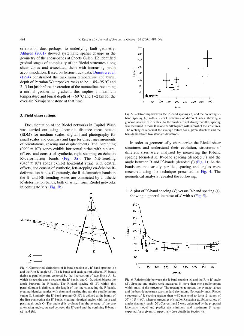
1. A plot of R0-band spacing (s0) versus R-band spacing (s),
showing a general increase of s0 with s (Fig. 5).
Fig. 4. Geometrical definitions of R-band spacing (s), R0-band spacing (s0)
and the R to R0 angle (b). The R-bands and each pair of adjacent R0-bands
define a parallelogram, centered by the intersection of two lines: A–B,
which bisects the angle between the R0-bands, and C–D, which bisects the
angle between the R-bands. The R-band spacing (E–E0) within this
parallelogram is defined as the length of the line connecting the R-bands,
creating identical angles with them and passing through the parallelogram
center O. Similarly, the R0-band spacing (G–G0) is defined as the length of
the line connecting the R0-bands, creating identical angles with them and
passing through O. The angle b is evaluated as the average of the two
alternating angles, created between the R0-band and the confining R-bands
(b1 and b2).
Fig. 5. Relationship between the R0-band spacing (s0) and the bounding R-
band spacing (s) within Riedel structures of different sizes, showing a
general increase of s0 with s. As the bands are not strictly parallel, spacing
was measured in more than one parallelogram within most of the structures.
The rectangles represent the average values for a given structure and the
bars demonstrate two standard deviations.
Fig. 6. Relationship between the R-band spacing (s) and the R to R0 angle
(b). Spacing and angles were measured in more than one parallelogram
within most of the structures. The rectangles represent the average values
and the bars demonstrate two standard deviations. Noticeably, most Riedel
structures of R spacing greater than ,80 mm tend to form b values of
358 , b , 608, whereas structures of smaller R spacing exhibit a variety of
angles that may reach 1208. Curves 1 and 2 were calculated by the proposed
kinematic model and predict the minimum and maximum b values
expected for a given s, respectively (see details in Section 4).
Y. Katz et al. / Journal of Structural Geology 26 (2004) 491–501494
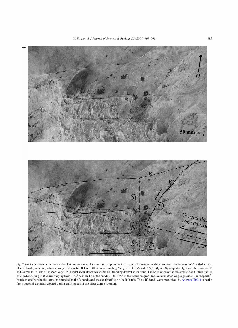
Fig. 7. (a) Riedel shear structures within E-trending sinistral shear-zone. Representative major deformation bands demonstrate the increase of b with decrease
of s. R0 band (thick line) intersects adjacent sinistral R-bands (thin lines), creating b angles of 60, 75 and 858 (b1, b2 and b3, respectively) as s values are 52, 38
and 24 mm (s1, s2 and s3, respectively). (b) Riedel shear structures within NE-trending dextral shear-zone. The orientation of the sinistral R0 band (thick line) is
changed, resulting in b values varying from ,458 near the tip of the band (b1) to ,908 in the interior region (b2). Several other long, sigmoidal-like shaped R0-
bands extend beyond the domains bounded by the R-bands, and are clearly offset by the R-bands. These R0-bands were recognized by Ahlgren (2001) to be the
first structural elements created during early stages of the shear zone evolution.
Y. Katz et al. / Journal of Structural Geology 26 (2004) 491–501 495

2. A plot of R-band spacing (s) versus the angle between R-
and R0-bands (b), showing a systematic relationship
between s and b (Fig. 6). Generally, Riedel structures
exhibiting values of s . 80 mm form angles of
358 , b , 608. Structures of s # 80 mm form a larger
range of angles, 358 , b , 1008, and in rare cases the angle
may reach 1208. The systematic relationship between s and
b and the significance of their lower and upper bound values
are demonstrated for an E-trending shear-zone (Fig. 7a). In
this case, an R0-band is displaced by sinistral R-bands and
divided into three segments. As R-band spacing s decreases,
the angleb between the segment and the bounding R-bands
increases such that b3 . b2 . b1. Fig. 7b shows a
NE-trending shear-zone, where dextral R-bands displace
and divide an R0-band into several segments. The angle b
varies from ,458 near the band’s tips (b1) to ,908 in the
interior region of the shear-zone (b2), where the R-bands are
closely spaced, corresponding to smaller values of s. This
variation results in segmented R0-bands with a general
trace geometry that resembles a sigmoidal-like shape.
3. Detailed examination of several shear zones reveals a
relationship between the relative age of the Riedel
structure and the angle between R- and R0-bands, b.
Commonly, young Riedel structures overprint old
structures within the shear zones (Fig. 8). In these
cases, the young structures exhibit smaller b angles than
those of the old structures (b2 . b1 in Fig. 8).
4. Examination of nested Riedel structures reveals a
systematic relationship between the relative age and
the spatial extent of the structure. Old Riedel
structures usually consist of widely spaced R- and
R0-bands (s and s0 are relatively high), and are widely
distributed across the shear-zone (see Figs. 8 and 9).
Young, overprinting Riedel structures exhibit a
denser band framework and tend to localize along
elongated domains sub-parallel to the shear direction.
Fig. 9 shows a complex network of Riedel structures
within a sinistral shear-zone. The primary Riedel
structure is widely spaced and extends across the
entire shear-zone. It is overprinted by succeeding
Fig. 7 (continued )
Y. Katz et al. / Journal of Structural Geology 26 (2004) 491–501496

secondary Riedel structures, which tend to localize into
dense networks.
4. Geometrical analysis and the impact of shear strain on
Riedel geometry
The field observations show a variety of Riedel structure
geometries. One possibility is that the structures originally
formed with different geometries due to variations in the
host-rock properties, stress states, ambient temperature or
pore pressure during their evolution. Alternatively, the
structures might have formed according to the basic Riedel
geometry and subsequently changed during progressive
deformation. As slip on deformation bands is limited, new
bands form during strain accommodation, and the spacing
between them is reduced. In addition, grain flow sub-
parallel to the R-bands, generated by the increasing stress,
may rotate the R0-bands to different orientations. Assuming
that different b angles measured between R- and R0-
deformation bands are a consequence of rotation, the
geometrical relationship between the R-spacing (s), the R
to R0 angle prior to rotation (b0) and after rotation (b), and
the overall displacement over the Riedel shear structure (d)
is given by (Fig. 10) (Ramsay and Huber, 1983):
tanb ¼tanb0
1 2 ðtanb0Þd
s
ð1Þ
This can be further expressed as:
d
s¼
sinðb2 b0Þ
sinb0sinbð2Þ
where d/s is the shear strain across the zone, defined
primarily by sub-parallel R-bands, and ðb2 b0Þ is the line
rotation angle.
In order to test the above model and establish the
relationship between s and b, measured values of b0 and d
were inserted into Eq. (2). b0 was measured directly within
structures showing no sign of rotation, and was found to
range from 35 to 558. This range is further supported
because it also resembles the angle between the large-scale
E- and NE-trending conjugate strike-slip faults (Fig. 3).
According to the Anderson (1942) theory of faulting, based
on the Mohr–Coulomb failure criterion, conjugate strike-
slip faults intersect at an angle of (90 2 f) where f is the
internal friction angle of the rock (f ¼ ,458 in the present
case study). As the R-bands and R0-bands within Riedel
structures may also be considered as conjugate sets, it is
reasonable that they were initially intersected by b0 ranging
from 35 to 558 as well. The measurements of d revealed
values up to 30 mm. According to the proposed model, both
b0 and d contribute to the final angle b. Curve 1 in the s
versus b data (Fig. 6) was calculated using the lowest values
of the b0 and d ranges (i.e. 358 and null displacement,
respectively) and predicts the minimum b values expected
for a given s. Curve 2 was calculated using the highest
values of the b0 and d ranges (558 and 30 mm, respectively)
and predicts the maximum b values expected for a given s.
Noticeably, most of the field measurements are incorporated
between these two theoretical curves, suggesting that the
proposed model is plausible.
5. Discussion
Differences in the Riedel structure geometry may occur
due to dissimilarities in rock properties, such as packing,
sorting, clay content and other factors governing the angle
of internal friction (Underhill and Woodcock, 1987). Moore
and Byerlee (1992) correlated geometrical variations to
different sliding behavior of the shear-zones, where small b
angles are associated with a stable slip and large b angles
with stick slip. They further proposed, based on laboratory
data, that larger b angles were favored by an increase in
temperature and effective pore pressure. The effect of pore-
fluid pressure on b values was also discussed by Gamond
(1983), Dresen (1991), Byerlee (1992) and Ahlgren (2001).
In the present study, field observations demonstrate
different b angles within adjacent and nested Riedel
Fig. 8. Young Riedel shear structure (thin lines) overprinting an old Riedel
shear structure (thick lines) within a sinistral shear-zone. The deformation
bands of the young structure create a denser framework and smaller b
angles (demonstrated by b1) compared with the spacing and b angles
(demonstrated by b2) of the old structure.
Y. Katz et al. / Journal of Structural Geology 26 (2004) 491–501 497

Fig. 9. Network of Riedel structures within a sinistral shear-zone. Widely-spaced, evenly distributed deformation bands forming a primary Riedel structure (thick
lines) are displaced by succeeding secondary, shorter R and R0-bands, which tend to localize into dense networks. Noticeably, the primary R0-bands form an angle of
,408 with the R-bands within domains of sparse deformation (b1). This angle is typically between 60 and 908 within the dense network domains (b2).
Y. Katz et al. / Journal of Structural Geology 26 (2004) 491–501498
structures. Considering the proximity in space, and perhaps
in time of the structures, it is unlikely that variations in rock
properties, temperature or pore pressure provide an
adequate explanation for the geometrical differences
documented in the field. Alternatively, geometrical differ-
ences may be a result of rotation, either of the stress field
due to local mechanical influences of the nearby propagat-
ing shear bands (Lajtai, 1969; Dresen, 1991; Shipton and
Cowie, 2001), or of the shear bands themselves following
their evolution (Jamison and Stearns, 1982; Mandl, 1987;
Arboleya and Engelder, 1995; An and Sammis, 1996;
Ahlgren, 2001). While not excluding the possibility of
stress-field rotation, the present observations provide
considerable evidence supporting the rotation of the shear
bands themselves as material markers. We therefore
propose that the deformation bands were originally oriented
according to the basic Riedel structure, and later rotated
during progressive deformation. As the deformation bands
divide the rock into blocks, it is possible that these blocks
rotated in a ‘bookshelf’ manner under simple shear (Mandl,
1987). This notion, however, raises three main caveats: (1)
the high porosity and minor cementation of the Navajo
sandstone do not favor rigid block rotation; (2) if such a
rotation occurred, material gaps and overlaps should have
been created along the block boundaries. Structural
consequences of these phenomena are not observed in the
field; (3) rotation should cause the edges of the blocks, i.e.
the R and R0-bands, to rotate by the same amount. However,
the field observations indicate substantial rotation of R0-
bands, yet little or no rotation of R-bands within the same
structures (e.g. Fig. 8).
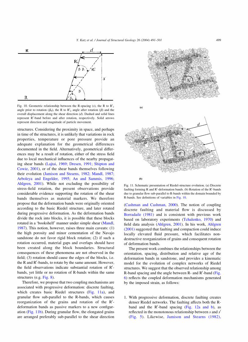
Therefore, we propose that two coupling mechanisms are
associated with progressive deformation: discrete faulting,
which creates basic Riedel structures (Fig. 11a), and
granular flow sub-parallel to the R-bands, which causes
reorganization of the grains and rotation of the R0-
deformation bands as passive markers to a new configur-
ation (Fig. 11b). During granular flow, the elongated grains
are arranged preferably sub-parallel to the shear direction
(Cashman and Cashman, 2000). The notion of coupling
discrete faulting and material flow is discussed by
Borradaile (1981) and is consistent with previous work
based on laboratory experiments (Tchalenko, 1970) and
field data analysis (Ahlgren, 2001). In his work, Ahlgren
(2001) suggested that faulting and compaction could induce
locally elevated fluid pressure, which facilitates non-
destructive reorganization of grains and consequent rotation
of deformation bands.
The present work combines the relationships between the
orientation, spacing, distribution and relative age of the
deformation bands in sandstone, and provides a kinematic
model for the evolution of complex networks of Riedel
structures. We suggest that the observed relationship among
R-band spacing and the angle between R- and R0-band (Fig.
6) reflects the coupled deformation mechanisms generated
by the imposed strain, as follows:
1. With progressive deformation, discrete faulting creates
denser Riedel networks. The faulting affects both the R-
band and the R0-band spacing (Fig. 12a and b), as
reflected in the monotonous relationship between s and s0
(Fig. 5). Likewise, Jamison and Stearns (1982),
Fig. 11. Schematic presentation of Riedel-structure evolution. (a) Discrete
faulting forming R and R0-deformation bands. (b) Rotation of the R0-bands
due to granular flow sub-parallel to R-bands within the domain bounded by
R-bands. See definitions of variables in Fig. 10.
Fig. 10. Geometric relationship between the R-spacing (s), the R to R01
angle prior to rotation (b0), the R to R02 angle after rotation (b) and the
overall displacement along the shear direction (d). Dashed and solid lines
represent R0-band before and after rotation, respectively. Solid arrows
represent direction and magnitude of particle movement.
Y. Katz et al. / Journal of Structural Geology 26 (2004) 491–501 499
Antonellini and Aydin (1995) and Mair et al. (2000)
reported a positive correlation between deformation-
band density and imposed strain. As shown in Fig. 5,
values of s0 which correspond to values of s , ,80 mm
tend to stabilize and average ,10 mm. This phenom-
enon may imply scaling of spacing with the average grain
size, and needs further research.
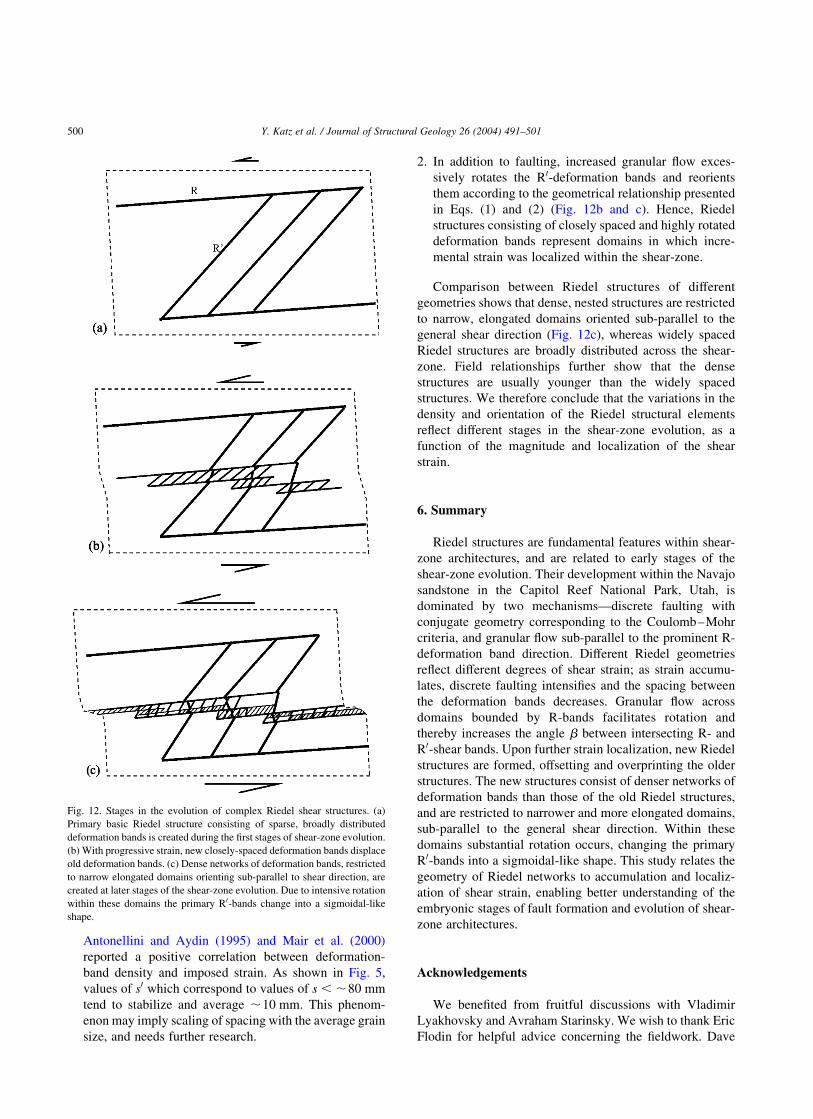
2. In addition to faulting, increased granular flow exces-
sively rotates the R0-deformation bands and reorients
them according to the geometrical relationship presented
in Eqs. (1) and (2) (Fig. 12b and c). Hence, Riedel
structures consisting of closely spaced and highly rotated
deformation bands represent domains in which incre-
mental strain was localized within the shear-zone.
Comparison between Riedel structures of different
geometries shows that dense, nested structures are restricted
to narrow, elongated domains oriented sub-parallel to the
general shear direction (Fig. 12c), whereas widely spaced
Riedel structures are broadly distributed across the shear-
zone. Field relationships further show that the dense
structures are usually younger than the widely spaced
structures. We therefore conclude that the variations in the
density and orientation of the Riedel structural elements
reflect different stages in the shear-zone evolution, as a
function of the magnitude and localization of the shear
strain.
6. Summary
Riedel structures are fundamental features within shear-
zone architectures, and are related to early stages of the
shear-zone evolution. Their development within the Navajo
sandstone in the Capitol Reef National Park, Utah, is
dominated by two mechanisms—discrete faulting with
conjugate geometry corresponding to the Coulomb–Mohr
criteria, and granular flow sub-parallel to the prominent R-
deformation band direction. Different Riedel geometries
reflect different degrees of shear strain; as strain accumu-
lates, discrete faulting intensifies and the spacing between
the deformation bands decreases. Granular flow across
domains bounded by R-bands facilitates rotation and
thereby increases the angle b between intersecting R- and
R0-shear bands. Upon further strain localization, new Riedel
structures are formed, offsetting and overprinting the older
structures. The new structures consist of denser networks of
deformation bands than those of the old Riedel structures,
and are restricted to narrower and more elongated domains,
sub-parallel to the general shear direction. Within these
domains substantial rotation occurs, changing the primary
R0-bands into a sigmoidal-like shape. This study relates the
geometry of Riedel networks to accumulation and localiz-
ation of shear strain, enabling better understanding of the
embryonic stages of fault formation and evolution of shear-
zone architectures.
Acknowledgements
We benefited from fruitful discussions with Vladimir
Lyakhovsky and Avraham Starinsky. We wish to thank Eric
Flodin for helpful advice concerning the fieldwork. Dave
Fig. 12. Stages in the evolution of complex Riedel shear structures. (a)
Primary basic Riedel structure consisting of sparse, broadly distributed
deformation bands is created during the first stages of shear-zone evolution.
(b) With progressive strain, new closely-spaced deformation bands displace
old deformation bands. (c) Dense networks of deformation bands, restricted
to narrow elongated domains orienting sub-parallel to shear direction, are
created at later stages of the shear-zone evolution. Due to intensive rotation
within these domains the primary R0-bands change into a sigmoidal-like
shape.
Y. Katz et al. / Journal of Structural Geology 26 (2004) 491–501500

Dewhurst, Susan Hippler and the Associated Editor, Don
Fisher, provided constructive and useful reviews of the
manuscript. We also thank Bevie Katz for language editing.
This study was supported by grant No. 9800198 from the
United States–Israel Binational Science Foundation (BSF),
Jerusalem, Israel.
References
Ahlgren, S.G., 2001. The nucleation and evolution of Riedel shear-zones as
deformation bands in porous sandstone. Journal of Structural Geology
23, 1203–1214.
An, L.-J., Sammis, C.G., 1996. Development of strike-slip faults: shear
experiments in granular materials and clay using a new technique.
Journal of Structural Geology 18, 1061–1077.
Anderson, E.M., 1942. The Dynamics of Faulting, 1st ed, Oliver and Boyd,
Edinburgh.
Antonellini, M.A., Aydin, A., 1994. Effects of faulting on fluid flow in
porous sandstones: petrophysical properties. American Association of
Petroleum Geologists Bulletin 78, 355–377.
Antonellini, M.A., Aydin, A., 1995. Effects of faulting on fluid flow in
porous sandstones: geometry and spatial distribution. American
Association of Petroleum Geologists Bulletin 79, 642–671.
Arboleya, M.L., Engelder, T., 1995. Concentrated slip zones with
subsidiary shears: their development on three scales in the Cerro
Brass fault zone, Appalachian valley and ridge. Journal of Structural
Geology 17, 519–532.
Aydin, A., 1978. Small faults formed as deformation bands in sandstones.
Pure and Applied Geophysics 116, 913–930.
Aydin, A., Johnson, A.M., 1978. Development of faults as zones of
deformation bands and as slip surfaces in sandstone. Pure and Applied
Geophysics 116, 931–942.
Baker, A.A., 1935. Geologic structure of southeastern Utah. American
Association of Petroleum Geologists Bulletin 19, 1472–1507.
Borradaile, G.J., 1981. Particulate flow of rock and formation of cleavage.
Tectonophysics 72, 305–321.
Byerlee, J., 1992. The change in orientation of subsidiary shears near faults
containing pore fluid under high pressure. Tectonophysics 211,
295–303.
Cashman, S., Cashman, C., 2000. Cataclasis and deformation-band
formation in unconsolidated marine terrace sand, Humboldt County,
California. Geology 28, 111–114.
Cloos, H., 1928. Experimenten zur inneren Tektonic. Centralblatt fur
Mineralogie und Paleontologie B, 609.
Cunningham, W.D., 1993. Strike-slip faults in the southernmost Andes and
the development of Patagonian orocline. Tectonics 12, 169–186.
Davatzes, N.C., Aydin, A., Eichhubl, P., 2003. Overprinting faulting
mechanisms during the development of multiple fault sets in sandstone,
Chimney Rock fault array, Utah, USA. Tectonophysics 363, 1–18.
Davis, G.H., 1999. Structural geology of the Colorado Plateau region of
southern Utah, with special emphasis on deformation bands. Geological
Society of America Special Paper 342, 157pp.
Davis, G.H., Bump, A.P., Garcia, P.E., Ahlgren, S.G., 1999. Conjugate
Riedel deformation band shear-zones. Journal of Structural Geology 22,
169–190.
Dresen, G., 1991. Stress distribution and the orientation of Riedel shears.
Tectonophysics 188, 239–247.
Dumitru, T.A., Duddy, I.A., Green, P.F., 1994. Mesozoic–Cenozoic burial,
uplift and erosion history of the west-central Colorado Plateau. Geology
22, 499–502.
Gamond, J.F., 1983. Displacement features associated with fault zones: a
comparison between observed examples and experimental models.
Journal of Structural Geology 5, 33–45.
Jamison, W.R., Stearns, D.W., 1982. Tectonic deformation of Wingate
sandstone, Colorado National Monument. American Association of
Petroleum Geologists Bulletin 66, 2584–2608.
Kelley, V.C., 1955. Monoclines of the Colorado Plateau. Geological
Society of America Bulletin 66, 789–803.
Kiersch, G.A., 1950. Small-scale structures and other features of Navajo
Sandstone, northern part of the San-Rafael Swell, Utah. American
Association of Petroleum Geologists Bulletin 34, 923–942.
Lajtai, E.Z., 1969. Mechanics of second order faults and tension gashes.
Geological Society of America Bulletin 80, 2253–2272.
Mair, K., Main, I., Elphick, S., 2000. Sequential growth of deformation
bands in the laboratory. Journal of Structural Geology 22, 25–42.
Mandl, G., 1987. Tectonic deformation by rotating parallel faults: the
“bookshelf” mechanism. Tectonophysics 141, 277–316.
Marzolf, J.E., 1983. Changing winds and hydraulic regimes during
deposition of the Navajo and Aztec sandstones, Jurassic(?) south-
western United States. In: Brookfield, M.E., Ahlbrandt, T.S. (Eds.),
Eolian Sediments and Processes, Elsevier, Amsterdam, pp. 635–660.
Marzolf, J.E., 1990. Reconstruction of extensionally dismembered early
Mesozoic sedimentary basins; southwestern Colorado Plateau to the
eastern Mojave Desert. In: Wernicke, B.P. (Eds.), Basin and Range
Extensional Tectonics near the Latitude of Las Vegas, Nevada.
Geological Society of America Memior 176, pp. 477–500.
Moore, D.E., Byerlee, J., 1992. Relationship between sliding behavior and
internal geometry of laboratory fault zones and some creeping and
locked strike-slip faults of California. Tectonophysics 211, 305–316.
Moore, J.M., 1979. Tectonics of the Najad transcurrent fault system, Saudi
Arabia. Journal of Geological Society of London 136, 441–452.
Naylor, M.A., Mandl, G., Sijpesteijn, C.H.K., 1986. Fault geometries in
basement-induced wrench faulting under different initial stress states.
Journal of Structural Geology 8, 737–752.
Ortlepp, W.D., 2000. Observation of mining-induced faults in an intact rock
mass at depth. International Journal of Rock Mechanics and Mining
Sciences 37, 423–436.
Ramsay, J.G., Huber, M.I., 1983. The Techniques of Modern Structural
Geology. Volume 1: Strain Analysis, Academic Press, London.
Riedel, W., 1929. Zur Mechanik Geologischer Brucherscheinungen.
Zentral-blatt fur Mineralogie, Geologie und Paleontologie B, 354–368.
Roznovsky, T.A., Aydin, A., 2001. Concentration of shearing deformation
related to changes in strike of monoclinal fold axes: the Waterpocket
monocline, Utah. Journal of Structural Geology 23, 1567–1579.
Shipton, Z.K., Cowie, P.A., 2001. Damage zone and slip-surface evolution
over mm to km scales in high-porosity Navajo sandstone, Utah. Journal
of Structural Geology 23, 1825–1844.
Tchalenko, J.S., 1968. The evolution of kink-bands and the development of
compression textures in sheared clays. Tectonophysics 6, 159–174.
Tchalenko, J.S., 1970. Similarities between shear-zones of different
magnitudes. Geological Society of America Bulletin 81, 1625–1640.
Underhill, J.R., Woodcock, N.H., 1987. Faulting mechanism in high-
porosity sandstones; New Red Sandstone, Arran, Scotland. In: Jones,
M.E., Prestone, R.M.F. (Eds.), Deformation of Sediments and
Sedimentary Rocks. Geological Society of London Special Publication,
29, pp. 91–105.
Y. Katz et al. / Journal of Structural Geology 26 (2004) 491–501 501