Geometry and Fields -...
46
Geometry Geometry and Fields: and Fields: Further and advanced features Further and advanced features J. Apostolakis & G. Cosmo J. Apostolakis & G. Cosmo
Transcript of Geometry and Fields -...

Geometry Geometry and Fields:and Fields:
Further and advanced featuresFurther and advanced featuresJ. Apostolakis & G. CosmoJ. Apostolakis & G. Cosmo

PART I
Detector DescriptionDetector DescriptionAdvanced featuresAdvanced features
Debugging toolsCreating geometry in simpler way
The Geant4 Geometrical Editor (tabular) Grouping volumesReflections of volumes and hierarchies
User defined solidsInterface to CAD systems

3
Debugging Debugging geometriesgeometries
An overlapping volume is a contained volume which actually protrudes from its mother volume
Volumes are also often positioned in a same volume with the intent of not provoking intersections between themselves. When volumes in a common mother actually intersect themselves are defined as overlapping
Geant4 does not allow for malformed geometriesThe problem of detecting overlaps between volumes is bounded by the complexity of the solid models descriptionUtilities are provided for detecting wrong positioning
Graphical tools (DAVID & OLAP)Kernel run-time commands

4
Debugging tools: DAVIDDebugging tools: DAVIDDAVID is a graphical debugging tool for detecting potential intersections of volumes
It intersects volumes directly, using their graphical representations.
Accuracy of the graphical representation can be tuned to the exact geometrical description.
physical-volume surfaces are automatically decomposed into 3D polygonsintersections of the generated polygons are parsed.If a polygon intersects with another one, the physical volumes associated to these polygons are highlighted in color (red is the default).
DAVID can be downloaded from the Web as external tool for Geant4
http://geant4.kek.jp/GEANT4/vis/DAWN/About_DAVID.html

5
Debugging runDebugging run--time commandstime commands
Built-in run-time commands to activate verification tests for the user geometry are defined
geometry/test/run or geometry/test/grid_testto start verification of geometry for overlapping regions based on a standard grid setup, limited to the first depth level
geometry/test/recursive_test
applies the grid test to all depth levels (may require lots of CPU time!)geometry/test/cylinder_test
shoots lines according to a cylindrical patterngeometry/test/line_test
to shoot a line along a specified direction and positiongeometry/test/position
to specify position for the line_testgeometry/test/direction
to specify direction for the line_test

6
Debugging runDebugging run--time commandstime commands -- 22
Example layout:
GeomTest: no daughter volume extending outside mother detected.GeomTest Error: Overlapping daughter volumes
The volumes Tracker[0] and Overlap[0],both daughters of volume World[0],appear to overlap at the following points in global coordinates: (list truncated)
length (cm) ----- start position (cm) ----- ----- end position (cm) -----240 -240 -145.5 -145.5 0 -145.5 -145.5
Which in the mother coordinate system are:length (cm) ----- start position (cm) ----- ----- end position (cm) -----
. . .Which in the coordinate system of Tracker[0] are:
length (cm) ----- start position (cm) ----- ----- end position (cm) -----. . .
Which in the coordinate system of Overlap[0] are:length (cm) ----- start position (cm) ----- ----- end position (cm) -----
. . .

7
Debugging tools: OLAPDebugging tools: OLAP
Uses tracking of neutral particles to verify boundary crossing in opposite directionsStand-alone batch application
Provided as extended exampleCan be combined with a graphical environment and GUI (ex. Qt library)Integrated in the CMS Iguana Framework

8
Debugging tools: OLAPDebugging tools: OLAP

9
Visualizing detector geometry treeVisualizing detector geometry tree
Built-in commands defined to display the hierarchical geometry tree
As simple ASCII text structureGraphical through GUI (combined with GAG)As XML exportable format
Implemented in the visualization moduleAs an additional graphics driver
G3 DTREE capabilities provided and more

10
The geometrical tree: example

11
GGE (Graphical Geometry Editor)GGE (Graphical Geometry Editor)
Implemented in JAVA, GGE is a graphical geometry editor compliant to Geant4. It allows to:
Describe a detector geometry including:materials, solids, logical volumes, placements
Graphically visualize the detector geometry using a Geant4 supported visualization system, e.g. DAWN Store persistently the detector description Generate the C++ code according to the Geant4 specifications
GGE can be downloaded from Web as a separate tool:http://erpc1.naruto-u.ac.jp/~geant4/

Grouping volumesGrouping volumes
To represent a regular pattern of positioned volumes, composing a more or less complex structure
structures which are hard to describe with simple replicas or parameterised volumesstructures which may consist of different shapes
Assembly volumeacts as an envelope for its daughter volumesits role is over once its logical volume has been placeddaughter physical volumes become independent copies in the final structure

13
G4AssemblyVolumeG4AssemblyVolumeG4AssemblyVolume( G4LogicalVolume* volume,
G4ThreeVector& translation,G4RotationMatrix* rotation);
Helper class to combine logical volumes in arbitrary wayParticipating logical volumes are treated as triplets
logical volume, translation, rotationImprints of the assembly volume are made inside a mother logical volume through G4AssemblyVolume::MakeImprint(…)Each physical volume name is generated automatically
Format: av_WWW_impr_XXX_YYY_ZZZWWW – assembly volume instance numberXXX – assembly volume imprint numberYYY – name of the placed logical volume in the assemblyZZZ – index of the associated logical volume
Generated physical volumes (and related transformations) are automatically managed (creation and destruction)

14
Assembly of volumes:Assembly of volumes:example example --11
// Define a plateG4VSolid* PlateBox = new G4Box( "PlateBox", plateX/2., plateY/2., plateZ/2. );G4LogicalVolume* plateLV = new G4LogicalVolume( PlateBox, Pb, "PlateLV", 0, 0, 0 );
// Define one layer as one assembly volumeG4AssemblyVolume* assemblyDetector = new G4AssemblyVolume();
// Rotation and translation of a plate inside the assemblyG4RotationMatrix Ra; G4ThreeVector Ta;
// Rotation of the assembly inside the worldG4RotationMatrix Rm;
// Fill the assembly by the platesTa.setX( caloX/4. ); Ta.setY( caloY/4. ); Ta.setZ( 0. );assemblyDetector->AddPlacedVolume( plateLV, G4Transform3D(Ra,Ta) );Ta.setX( -1*caloX/4. ); Ta.setY( caloY/4. ); Ta.setZ( 0. );assemblyDetector->AddPlacedVolume( plateLV, G4Transform3D(Ra,Ta) );Ta.setX( -1*caloX/4. ); Ta.setY( -1*caloY/4. ); Ta.setZ( 0. );assemblyDetector->AddPlacedVolume( plateLV, G4Transform3D(Ra,Ta) );Ta.setX( caloX/4. ); Ta.setY( -1*caloY/4. ); Ta.setZ( 0. );assemblyDetector->AddPlacedVolume( plateLV, G4Transform3D(Ra,Ta) );
// Now instantiate the layersfor( unsigned int i = 0; i < layers; i++ ) {
// Translation of the assembly inside the worldG4ThreeVector Tm( 0,0,i*(caloZ + caloCaloOffset) - firstCaloPos );assemblyDetector->MakeImprint( worldLV, G4Transform3D(Rm,Tm) );
}

Assembly of volumes: example Assembly of volumes: example --22

16
Reflecting solidsReflecting solids
G4ReflectedSolid
utility class representing a solid shifted from its original reference frame to a new reflected onethe reflection (G4Reflect[X/Y/Z]3D) is applied as a decomposition into rotation and translation
G4ReflectionFactory
Singleton object using G4ReflectedSolid for generating placements of reflected volumes
Reflections can be applied to CSG and specific solids

17
Reflecting hierarchies of volumes Reflecting hierarchies of volumes -- 11
G4ReflectionFactory::Place(…)Used for normal placements:
i. Performs the transformation decompositionii. Generates a new reflected solid and logical volume
Retrieves it from a map if the reflected object is already creatediii. Transforms any daughter and places them in the given motheriv. Returns a pair of physical volumes, the second being a placement in the
reflected motherG4PhysicalVolumesPairPlace(const G4Transform3D& transform3D, // the transformation
const G4String& name, // the actual nameG4LogicalVolume* LV, // the logical volumeG4LogicalVolume* motherLV, // the mother volumeG4bool noBool, // currently unusedG4int copyNo) // optional copy number

18
Reflecting hierarchies of volumes Reflecting hierarchies of volumes -- 22
G4ReflectionFactory::Replicate(…)
Creates replicas in the given mother volumeReturns a pair of physical volumes, the second being a replica in the reflected mother
G4PhysicalVolumesPair
Replicate(const G4String& name, // the actual nameG4LogicalVolume* LV, // the logical volume
G4LogicalVolume* motherLV, // the mother volumeEaxis axis // axis of replicationG4int replicaNo // number of replicas
G4int width, // width of single replicaG4int offset=0) // optional mother offset

19
User defined solidsUser defined solids
All solids should derive from G4VSolid and implement its abstract interface
will guarantee the solid is treated as any other solid predefined in the kernel
Basic functionalities required for a solidCompute distances to/from the shapeDetect if a point is inside the shapeCompute the surface normal to the shape at a given pointCompute the extent of the shapeProvide few visualization/graphics utilities

20
What a solid should reply toWhat a solid should reply to……-- 11
EInside Inside(const G4ThreeVector& p) const;
Should return, considering a predefined tolerance:kOutside - if the point at offset p is outside the shapes boundarieskSurface - if the point is close less than Tolerance/2 from the surfacekInside - if the point is inside the shape boundaries
G4ThreeVector SurfaceNormal(const G4ThreeVector& p) const;
Should return the outwards pointing unit normal of the shape for the surface closest to the point at offset p.
G4double DistanceToIn(const G4ThreeVector& p,const G4ThreeVector& v) const;
Should return the distance along the normalized vector v to the shape from the point at offset p. If there is no intersection, returns kInfinity. The first intersection resulting from ‘leaving' a surface/volume is discarded. Hence, it is tolerant of points on the surface of the shape

21
What a solid should reply toWhat a solid should reply to……-- 22G4double DistanceToIn(const G4ThreeVector& p) const;
Calculates the distance to the nearest surface of a shape from an outside point p. The distance can be an underestimate
G4double DistanceToOut(const G4ThreeVector& p,
const G4ThreeVector& v,const G4bool calcNorm=false,
G4bool* validNorm=0,
G4ThreeVector* n=0) const;
Returns the distance along the normalised vector v to the shape, from a point at an offset p inside or on the surface of the shape. Intersections with surfaces, when the point is less than Tolerance/2 from a surface must be ignored. If calcNorm is true, then it must also set validNorm to either:
True - if the solid lies entirely behind or on the exiting surface. Then it must set n to the outwards normal vector (the Magnitude of the vector is not defined)False - if the solid does not lie entirely behind or on the exiting surface
G4double DistanceToOut(const G4ThreeVector& p) const;
Calculates the distance to the nearest surface of a shape from an inside point p. The distance can be an underestimate

22
Solid: more functionsSolid: more functions……
G4bool CalculateExtent(const EAxis pAxis,const G4VoxelLimits& pVoxelLimit,const G4AffineTransform& pTransform,
G4double& pMin, G4double& pMax) const;
Calculates the minimum and maximum extent of the solid, when under the specified transform, and within the specified limits. If the solid is not intersected by the region, returnfalse, else return true
Member functions for the purpose of visualization:
void DescribeYourselfTo (G4VGraphicsScene& scene) const;
“double dispatch” function which identifies the solid to the graphics scene
G4VisExtent GetExtent () const;
Provides extent (bounding box) as possible hint to the graphics view

Interface to CAD systemsInterface to CAD systemsModels imported from CAD systems can describe the solid geometry of detectors made by large number of elements with the greatest accuracy and detail
A solid model contains the purely geometrical data representing the solids and their position in a given reference frameMaterial information is generally missing
Solid descriptions of detector models could be imported from CAD systems
e.g. Euclid & Pro/Engineer using STEP AP203 compliant protocol
Tracking in BREP solids created through CAD systems was supported
but since Geant4 5.2 the old NIST derived STEP reader can no longer be supported.

How to import CAD geometriesHow to import CAD geometries
Detector geometry description should be modularizedBy sub-detector and sub-detector componentsEach component in a separate STEP file
G4AssemblyCreator and G4Assembly classes from the STEPinterface module should be used to read a STEP file generated by a CAD system and create the assembled geometry in Geant4
Geometry is generated and described through BREP shapesGeometry modules for each component are assembled in the user code

25
Importing STEP models:Importing STEP models:example example --11
G4AssemblyCreator MyAC("tracker.stp");// Associate a creator to a given STEP file.
MyAC.ReadStepFile();// Reads the STEP file.
STEPentity* ent=0;// No predefined STEP entity in this example.// A dummy pointer is used.
MyAC.CreateG4Geometry(*ent);// Generates GEANT4 geometry objects.
void *pl = MyAC.GetCreatedObject();// Retrieve vector of placed entities.
G4Assembly* assembly = new G4Assembly();// An assembly is an aggregation of placed entities.
assembly->SetPlacedVector(*(G4PlacedVector*)pl);// Initialise the assembly.

26
Importing STEP models:Importing STEP models:example example -- 22
G4int solids = assembly->GetNumberOfSolids();
// Get the total number of solids among all entities.for(G4int c=0; c<solids; c++)
// Generate logical volumes and placements for each solid.{
ps = assembly->GetPlacedSolid(c);
G4LogicalVolume* lv =new G4LogicalVolume(ps->GetSolid(), Lead, "STEPlog");
G4RotationMatrix* hr = ps->GetRotation();G4ThreeVector* tr = ps->GetTranslation();G4VPhysicalVolume* pv =
new G4PVPlacement(hr, *tr, ps->GetSolid()->GetName(),lv, experimentalHall_phys, false, c);
}

PART II
Electromagnetic Fields Electromagnetic Fields

28
Field Contents
1. What is involved in propagating in a field 2. A first example
• Defining a field in Geant43. More capabilities4. Understanding and controlling the
precision

29
Magnetic field: overviewIn order to propagate a particle inside a field (e.g. magnetic, electric or both), we solve the equation of motion of the particle in the field. We use a Runge-Kutta method for the integration of the ordinary differential equations of motion.
Several Runge-Kutta ‘steppers’ are available.In specific cases other solvers can also be used:
In a uniform field, using the analytical solution.In a nearly uniform field (BgsTransportation/future)In a smooth but varying field, with new RK+helix.

30
Magnetic field: overview (cont)Using the method to calculate the track's motion in a field, Geant4 breaks up this curved path into linear chord segments.
We determine the chord segments so that they closely approximate the curved path. We use the chords to interrogate the Navigator, to see whether the track has crossed a volume boundary.
31
Stepping and accuracyYou can set the accuracy of the volume intersection,
by setting a parameter called the “miss distance”it is a measure of the error in whether the approximate track intersects a volume. Default “miss distance” is 3 mm.
One physics/tracking step can create several chords.In some cases, one step consists of several helix turns.
miss distance
‘Tracking’ StepChords
real trajectory

32
Magnetic field: a first exampleCreate your Magnetic field class
Uniform field : Use an object of the G4UniformMagField class
#include "G4UniformMagField.hh"#include "G4FieldManager.hh"#include "G4TransportationManager.hh“
G4MagneticField* magField= new G4UniformMagField( G4ThreeVector(1.0*Tesla,
0.0, 0.0 );
Non-uniform field :Create your own concrete class derived from G4MagneticField
Part 1/2

33
Magnetic field: a first example Tell Geant4 to use your field
Find the global Field ManagerG4FieldManager* globalFieldMgr= G4TransportationManager::GetTransportationManager()
->GetFieldManager();
Set the field for this FieldManager,globalFieldMgr->SetDetectorField(magField);
and create a Chord Finder.globalFieldMgr->CreateChordFinder(magField);
Part 2/2

34
In practice: exampleN04From geant4/examples/novice/N04/src/ExN04DetectorConstruction.cc
G 4 V P h y s i c a l V o l u m e * E x N 0 4 D e t e c t o r C o n s t{ / / - - - - - - - - - - - - - - - - - - - - - - - - - - - - - - - - - / / M a g n e t i c f i e l d / / - - - - - - - - - - - - - - - - - - - - - - - - - - - - - - - - -
s t a t i c G 4 b o o l f i e l d I s I n i t i a l i z e d = i f ( ! f i e l d I s I n i t i a l i z e d ) { E x N 0 4 F i e l d * m y F i e l d = n e w E x N 0 4 F i G 4 F i e l d M a n a g e r * f i e l d M g r = G 4 T r a n s p o r t a t i o n M a n a g e r : : G e t T - > G e t F i e l d M a n a g e r ( ) ; f i e l d M g r - > S e t D e t e c t o r F i e l d ( m y F i e l f i e l d M g r - > C r e a t e C h o r d F i n d e r ( m y F i e f i e l d I s I n i t i a l i z e d = t r u e ; }

35
Beyond your first fieldCreate your own field class
To describe your setup’s EM fieldGlobal field and local fields
The world or detector field managerAn alternative field manager can be associated with any logical volume
Currently the field must accept position global coordinates and return field in global coordinates
Customizing the field propagation classesChoosing an appropriate stepper for your fieldSetting precision parameters

36
Creating your own fieldCreate a class, with one key method – that calculates the
value of the field at a PointPoint [0..2] positionPoint[3] timevoid ExN04Field::GetFieldValue(
const double Point[4],double *field) const
{field[0] = 0.;field[1] = 0.;if(abs(Point[2])<zmax && (sqr(Point[0])+sqr(Point[1]))<rmax_sq){ field[2] = Bz; }else{ field[2] = 0.; }
}

37
Global and local fieldsOne field manager is associated with the ‘world’
Set in G4TransportationManagerOther volumes can override this
By associating a field manager with any logical volumeBy default this is propagated to all its daughter volumes
G4FieldManager* localFieldMgr=new G4FieldManager(magField);
logVolume->setFieldManager(localFieldMgr, true);
where ‘true’ makes it push the field to all the volumes it contains.

38
Precision parameters
Errors come fromBreak-up of curved trajectory into linear chords Numerical integration of equation of motion
or potential approximation of the path,
Intersection of path with volume boundary.Precision parameters enable the user to limit these errors and control performance.
The following slides attempt to explain these parameters and their effects.

39
Volume miss error
Parameter δchord
Effect of this parameter as δchord 0s1step
propagator ~ (8 δchord R curv)1/2
Due to the approximation of the curved path by linear sections (chords)
so long as spropagator < s phys and spropagator > dminintegr
dchord < δchord
δchord
dchordParameter
value
=

40
Integration errorDue to error in the numerical integration (of
equations of motion)
Parameter(s): εintegration
max( || ∆r || / sstep , ||∆p|| / ||p|| ) < εintegration
It limits the size of the integration step.For ClassicalRK4 Stepper
s1stepintegration ~ (εintegration)1/3
for small enough εintegrationThe integration error should be influenced by the precision of the knowledge of the field (measurement or modeling ).
s1step
∆rNsteps ~ (εintegration)-1/3

41
Integration errors (cont.)In practice
εintegration is currently represented by 3 parametersepsilonMin, a minimum value (used for big steps)epsilonMax, a maximum value (used for small steps)DeltaOneStep, a distance error (for intermediate steps)
εintegration= δ one step / s physics
Determining a reasonable valueI suggest it should be the minimum of the ratio (accuracy/distance) between sensitive components, ..
Another parameterdmin is the minimum step of integration
(newly enforced in Geant4 4.0)
Defaults0.5*10-7
0.050.25 mm
Default0.01 mm

42
Intersection errorIn intersecting approximate path with volume boundary
In trial step AB, intersection is found with a volume at CStep is broken up, choosing D, so
SAD = SAB * |AC| / |AB|
If |CD| < δintersectionThen C is accepted as intersection point.
So δint is a position error/bias
A
C
B
D
SAD
p
43
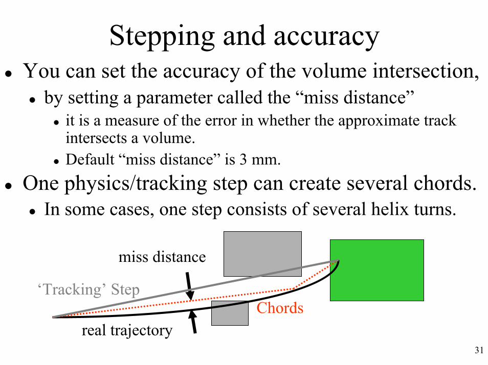
Intersection error (cont)So δint must be small
compared to tracker hit errorIts effect on reconstructed momentum estimates should be calculated
And limited to be acceptable
Cost of small δint is lessthan making δchord smallIs proportional to the number of boundary crossings – not steps.
Quicker convergence / lower costPossible with optimization
adding std algorithm, as in BgsLocation
D
A
E
F
If C is rejected,a new intersectionpoint E is found.E is good enough• if |EF| < δint

44
The ‘driving force’Distinguish cases according to the factor driving the tracking step length
‘physics’, eg in dense materialsfine-grain geometry
Distinguish the factor driving the propagator step length (if different)
Need for accuracy in ‘seeing’ volumeIntegration inaccuracy
Strongly varying field
Potential Influence
G4 Safety improvement
Other Steppers,tuning dmin

45
Where to find the parameters
0.05PropagatorInFieldepsilonMax5 10-7PropagatorInFieldepsilonMin
0.25 mmFieldManagerDeltaOneStepδ one step
0.10 mmFieldManagerDeltaIntersectionδintersection
0.01 mmChordFinderstepMinimumdmin
3.0 mmChordFinderDeltaChordδmiss
DefaultClassNameParameter

46
What if time does not change much?If adjusting these parameters (together) by a significant factor (10 to 100) does not produce results,
Then it is likely that the field propagation is not the dominant (most CPU intensive) part of your program.Look into alternative measures
modifying the physics ‘cuts’ – ie production thresholdsTo create fewer secondaries, and so track fewer particles
determining the number of steps of neutral vs charged particles,
To find whether neutrons, gammas ‘dominate’profiling your application
You can compile using G4PROFILE=yes, run your program and then use “gprof” to get an execution profile.