Meshing of a detailed DrivAer Body with ANSYS Meshing and ...
Upload
lily-batesCategory
view
224download
1
Geometry Abstraction &
Section Meshing
Geometry Abstraction &
Section Meshing
2001 Simulation Seminar
2001

Get There Faster™
Geometric Abstraction and MeshingGeometric Abstraction and Meshing
Design Geometry Realities

Get There Faster™
• Quickly pass through the model
construction phase- Engineering begins after the results are available
Geometry EffectsGeometry Effects
Geometry is the Geometry is the biggest inhibitor to biggest inhibitor to meshing efficiencymeshing efficiency
Geometry provides Geometry provides the most promise to the most promise to CAE impacting CAE impacting design activitiesdesign activities
“Design Engineer needs complete, high quality mesh of any automotive component in less than ½ day”.
Hiroyuki Umetanimanager, Development Dept.Information SystemsToyota Motor Corporation

Get There Faster™
A Break-Down of the CAE ProcessA Break-Down of the CAE Process
• What is the most time consuming process?
Post Processing9% Percentage of TimePercentage of Time
Geometry Creation
42%
SDRC, 1997
Solve4%
Boundary Conditions
9%
Mesh Generation17% Prepare Geometry
for Export
6%
Repair Imported Geometry
13%

Get There Faster™
Direction of SDRC’s CAEDirection of SDRC’s CAE
• Much Focus on Pre-Processing
• Automatic & Robust Tool for building FE Model
Tim
eT
ime
IterationIteration11
Before
Today

Get There Faster™
Improvements during MS5 - MS7Improvements during MS5 - MS7• Some examples of the reduction time to build FE Model
0
5
10
15
20
Time (hours)
MS5 MS6 MS7
Crank Shaft
Bracket
1/101/10
1/501/50

Get There Faster™
Powerful Geometry AbstractionPowerful Geometry Abstraction
•Part contains 300 surfaces. Abstracted to 24 meshing regions

Get There Faster™
Customer EndorsementsCustomer Endorsements
• ZF Automotive supplier to many major OEM’s of
Driveline and chassis technology- Complex parts/assemblies (I.e. transmission cases)
• “Almost 30% development time saved by using I-DEAS
Section Meshing Technology”Dr. Kelkel
ZF, Germany

Get There Faster™
Typical Design GeometryTypical Design Geometry
• Topology Issues- small edges
- compound edges
- sliver surfaces
- high aspect ratio
- missing surfaces
- topology too detailed
- reconstruction
Get There Faster™
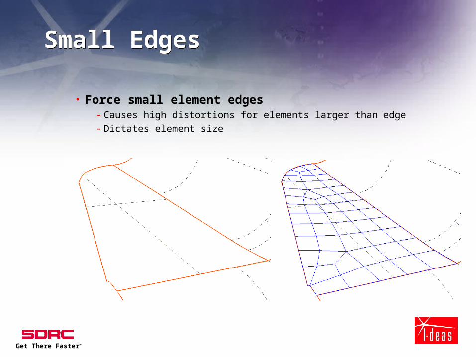
Small EdgesSmall Edges
• Force small element edges- Causes high distortions for elements larger than edge- Dictates element size

Get There Faster™
Sliver SurfacesSliver Surfaces
• Narrow surface which causes distortions
and stretched elements

Get There Faster™
Disconnected SurfacesDisconnected Surfaces
• Surfaces which are not “stitched” together do not
share the same edges
• Causes discontinuous mesh that do not allow forces
to transfer across the discontinuity

Get There Faster™
Poorly Parameterized SurfacesPoorly Parameterized Surfaces• Surfaces which do not have evenly spaced iso
lines do not have evenly spaced parameter space
in 3D
• Results in skewed and stretched elements
• Especially in imported geometry

Get There Faster™
Meshing algorithmsMeshing algorithms
• Bounded by surface shape and
boundaries- can distort elements beyond usefulness
- dictates element size

Get There Faster™
Section MeshingSection Meshing
• Expands the boundaries of surfaces- relaxes mesh area therefore improving quality of elements
- removes boundary and shape constraints that negatively effects meshing

Get There Faster™
Section MeshingSection Meshing
• Permits edge connectors to be removed- Removes requirement of having at least one
element/edge
- Relaxes elements and therefore improves mesh quality

Get There Faster™
Too Much DetailToo Much Detail
• Small holes usually have adverse effect
on mesh- increases number of nodes/elements in unimportant area
of model
- can distort elements because of local curvature
- but are internal boundaries which meshing algorithms must address

Get There Faster™
Too Much DetailToo Much Detail
• Often only one single node is needed to
represent hole for boundary condition
definition
• model more efficient
Get There Faster™
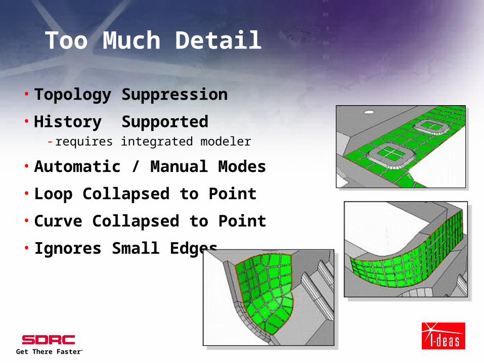
Too Much Detail
• Topology Suppression
• History Supported- requires integrated modeler
• Automatic / Manual Modes
• Loop Collapsed to Point
• Curve Collapsed to Point
• Ignores Small Edges
Get There Faster™
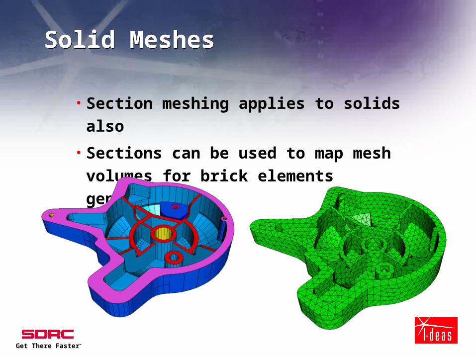
Solid MeshesSolid Meshes
• Section meshing applies to solids also
• Sections can be used to map mesh
volumes for brick elements generation

Get There Faster™
Section MeshingSection Meshing
• Capture Analysis Intent- User Control- Puts the model size (degrees of freedom) within the
control of the user- Does not change the geometry (surfaces, edges, . ) of
the part- Overhead minimal because no additional geometry is
created- all nodes are on original surfaces and elements can span
surface boundaries- Integrity of part is intact
In Short Section Meshing has become the preferred In Short Section Meshing has become the preferred meshing approach to all types of partsmeshing approach to all types of parts

Get There Faster™
Where do I start?Where do I start?
• I know I can abstract my model but with
complex models - How do I find the problem areas?
- What element size should I use?
- How much time should I spend abstracting?
Get There Faster™
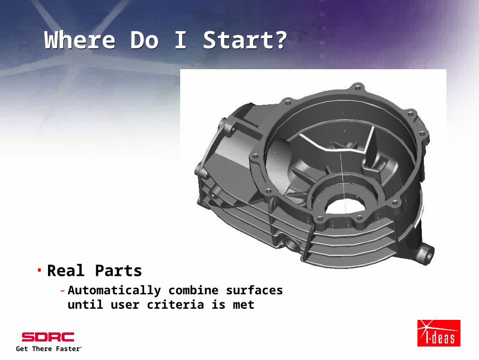
Where Do I Start?Where Do I Start?
• Real Parts- Automatically combine surfaces until user
criteria is met

Get There Faster™
Surface and Section Quality ChecksSurface and Section Quality Checks
• The meshing job is a balance of FEM size (element
size) and how much interaction the user wants to
go through to get the element size he wants
• In the past modeling time was unpredictable
because it was impossible to anticipate how many
of these problem situations would arise
Try element size
Fail
Mesher

Get There Faster™
Quality CheckQuality Check
• Find small edges
• Find sliver surfaces
• Find small holes
• Show me
expendable
connectors

Get There Faster™
Quality ChecksQuality Checks
• Highlight problem
geometry

Get There Faster™
Quality ChecksQuality Checks
• How many bad surfaces do I have?
• Indicates - how much work I have to do to
make useable mesh based on criteria
- if not many I know what element size this geometry will take
- if checks are made on sections, then same indications are available and user knows how much work is left
• Continue until all sections disappear
Get There Faster™
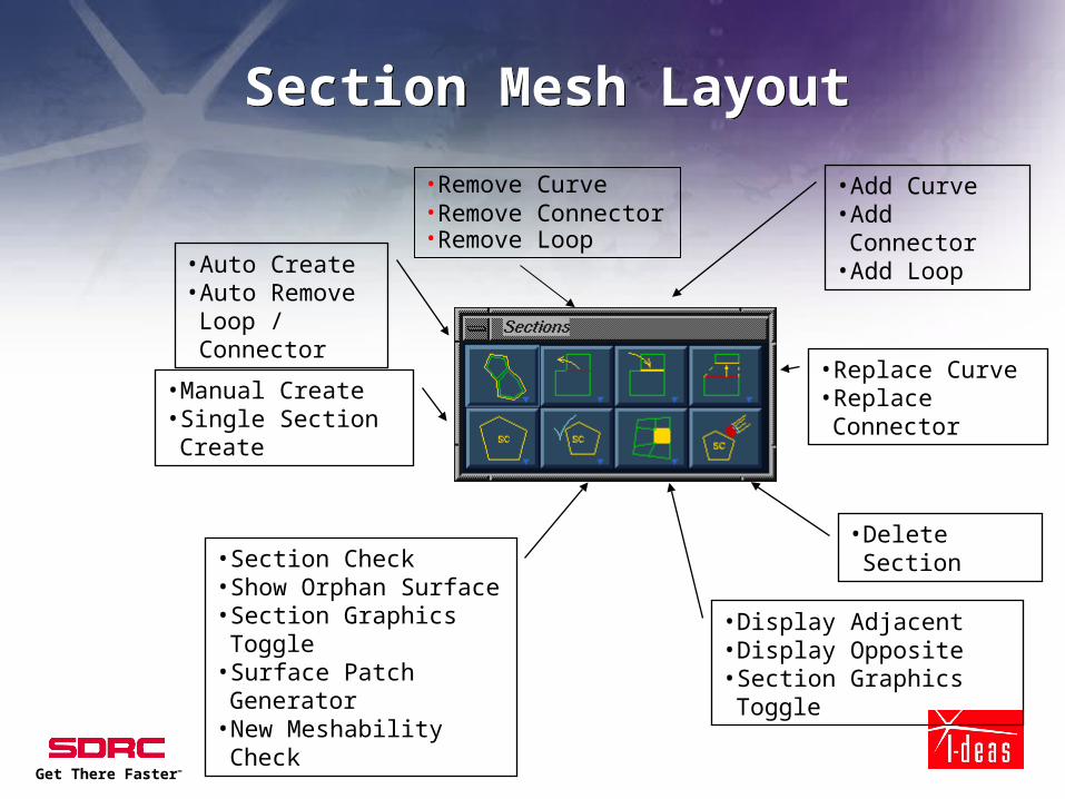
Section Mesh LayoutSection Mesh Layout
• Auto Create• Auto Remove
Loop / Connector
• Manual Create• Single Section Create
• Display Adjacent• Display Opposite• Section Graphics Toggle
• Section Check• Show Orphan Surface• Section Graphics Toggle• Surface Patch Generator• New Meshability Check
• Replace Curve• Replace Connector
• Add Curve• Add Connector• Add Loop
• Delete Section
•Remove Curve•Remove Connector•Remove Loop

Results ResultsIsthmus Surface from IGES
Collapsed region Resulting Single Sectionmulti-looped section
Mesh on the Section

Results ResultsIsthmus Section now combined with adjacent sections using new functionality
Resulting Mesh

Results Results
Isthmus Surface
Resulting Section
Resulting Mesh

Original Surface
MS8 Replace CurveMS8 Replace Curve
Replace A portion of one curve with the other

Replace Curve Replace Curve
Eliminated the pinched area with Replace Curve
Resulting Mesh

Replace Curve Replace Curve
Replace Curve Maintains connection with other sections

Get There Faster™
Mid-Surface Challenges for Section MeshMid-Surface Challenges for Section Mesh
Surfaces aren’t
extended to wall
Surfaces aren’t
trimmed back
and stitched
Surface extend fail
A straight Automatic
Pairing produces this
Get There Faster™
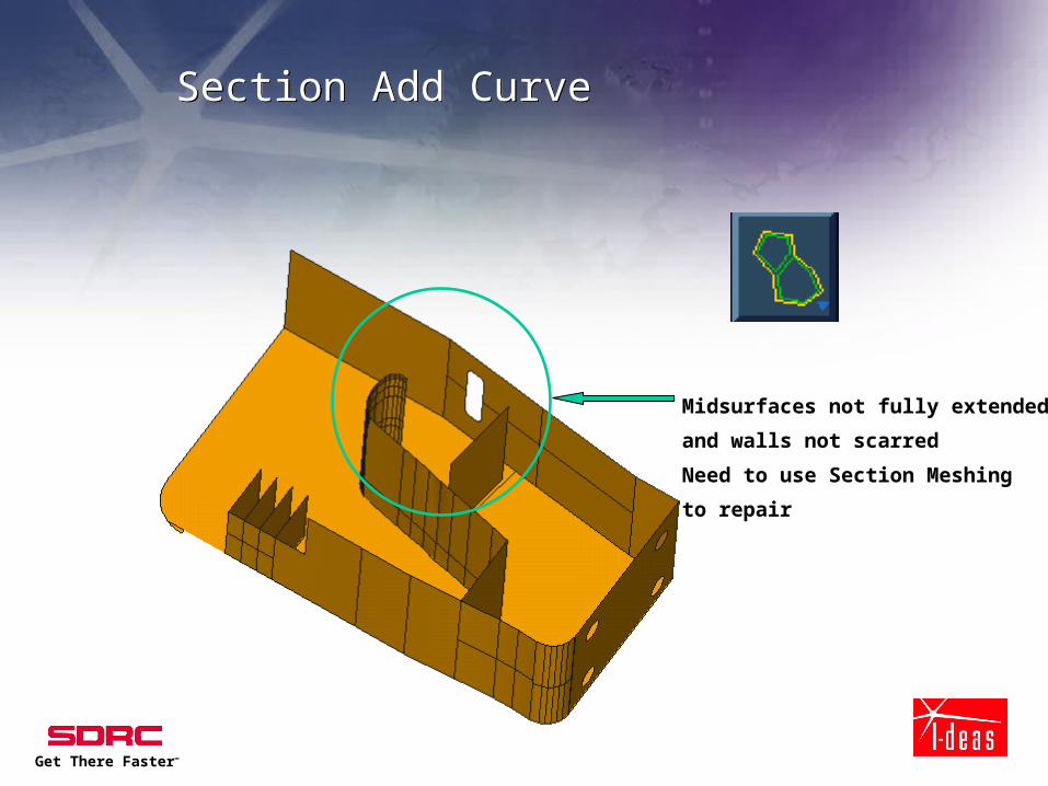
Section Add Curve Section Add Curve
Midsurfaces not fully extended
and walls not scarred
Need to use Section Meshing
to repair

Get There Faster™
Gap too large for auto section to closeGap too large for auto section to close

Get There Faster™
Project surface boundary and replaceProject surface boundary and replace
User
1) Adds Curve projecting
original edge of surface
2) Replace original curve
with projected

Get There Faster™
Quality ChecksQuality Checks
• All geometric problems anticipated
• Meshing reduced to one iteration in most cases

Get There Faster™
Meshing Issues - Tet HexMeshing Issues - Tet Hex
• Tet Hex meshing allow mixing of
Parabolic Tets with Bricks
• Multipoint Constraint elements (MPCs) tie up loose mid nodes

Get There Faster™
Meshing Issues - Manual Control Meshing Issues - Manual Control
Element Project/Element, Orient Off Geometry, Project Element Collapse
/Check Mesh, Element Collapse

Get There Faster™
Meshing Issues - Manual ControlMeshing Issues - Manual Control
Element Extrude Normal

Get There Faster™
Meshing IssuesMeshing Issues
• Element Collapse (under the Quality Checks icon stack)
- Collapse narrow (stretched) linear or parabolic triangular shells

Get There Faster™
Mesh GenerationsMesh Generations
• Brick Elements from shell projection

Get There Faster™
Mesh GenerationMesh Generation
• Project Elements to Surface

Get There Faster™
Augmentation of GeometryAugmentation of Geometry
• Geometric information; physical representation- Additional structure.- Calculation surface to measure energy propagation.- Contact regions, FEM or geometry based.- Weld attachments, reference series of locations
• Non-geometric information; non-physical
representation- interpolated surfaces.- lumped masses, springs, or beams.- gaps, coupled dofs, or constraint equations.

Get There Faster™
Adaptation of the FEMAdaptation of the FEM
• Associative to design definition- geometry change
- abstraction change
- boundary conditions
- loading conditions
- surface mapping
• Surface mapping/compare parts- domestic/imported

Get There Faster™
Mesh GenerationMesh Generation
• Many new options and features for mesh
construction, including:- Automatic tetrahedral to hexahedral interface
- Create Thickness Results
- Element Extrude Normal
- Element Project
- Element Collapse

Get There Faster™
Improve Elements’ QualityImprove Elements’ Quality
• Nodes Drag - Viewing quality values- Improve surface mesh quality
• Auto Settings during meshing- Automatic Mesh Checking & Improvement
• Tetra Fix- Move Mid Nodes + Straighten Edge
• Plump- Fix Flat tet elements

Get There Faster™
Integrated CAE with 3D/CADIntegrated CAE with 3D/CAD
• Surfaces Mapping - Imported Geometry from other CAD
Replace Orphaned Surfaces
Update Mesh on orphaned surfaces

Get There Faster™
Surface MappingSurface Mapping
• Can foreign CAD geometry be Associative to FE data?
• What if the model is a mixture of foreign CAD surfaces and I-DEAS generated geometry complete with history?
Foreign Foreign CADCAD

Get There Faster™
Surface MappingSurface Mapping
• Section meshing used to define
meshing regions

Get There Faster™
Surface MappingSurface Mapping
• New design introduced from packaging detail design work
• User can map new surfaces, edges, and surface normals into correct orientation for feature replacement

Get There Faster™
Surface MappingSurface Mapping
• Associativity reintroduced to the FEM from the mapping process
• Additional features beyond mapped geometry automatically maintained

Get There Faster™
Non-geometric RepresentationNon-geometric Representation
• Midsurface
• Weld points- usually modeled with rigid elements or couples
• Rigid bodies which I do not want to mesh- usually modeled with lumped masses and rigid element- issues about connections and associativity
• Connections to other components which transfer force but not infinitely stiff
- most conveniently modeled between two point with beams and possibly use of some rigid elements
- bolt connections
• Contacting surfaces between two bodies or portions of same part

Get There Faster™
Non-Geometric entitiesNon-Geometric entities
• Rigid elements for U joint link
• Automated meshers need to recognize connection points between nodes on the hole and rigid element connections

Get There Faster™
Non-Geometric entities Non-Geometric entities
• Spring elements and lumped masses need to be associative to the model which are meshed on modeled geometry
Get There Faster™
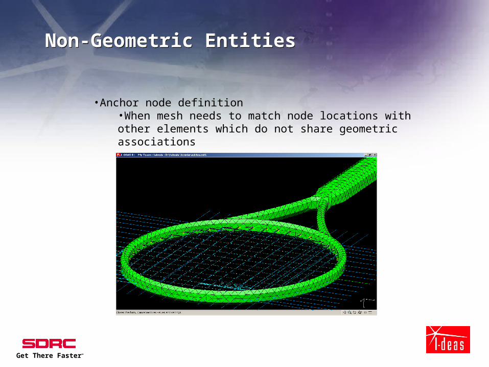
Non-Geometric EntitiesNon-Geometric Entities
•Anchor node definition•When mesh needs to match node locations with other elements which do not share geometric associations

Get There Faster™
Spot WeldSpot Weld
• Automatic meshing of entities without geometry
Spot weld every 40mm
3D points projected onto surface defines meshing node location creates associative element definition for rigid bar or spring

Get There Faster™
SummarySummary
• Section meshing has become the preferred
meshing approach to all model situations where
shell and solid elements are automatically
generated
• Geometry playing a more important role in FE
efficiency- for the CAE processes to have a more positive impact on the
design- to make it a reality to evaluate as many design alternatives- automatically update the design from parameter studies and
optimization activities