Geometric Stiffness and P-Delta Effects
14
GEOMETRIC STIFFNESS AND P- DELTA EFFECTS P-Delta Effects, Due To Dead Load, Can Be Considered Without Iteration For Both Static And Dynamic Analysis 11.1. DEFINITION OF GEOMETRIC STIFFNESS We are all aware that a cable, when subjected to a large tension force, has an increased lateral stiffness. If a long rod is subjected to a large compressive force, and is on the verge of buckling, we know that the lateral stiffness of the rod has been reduced significantly and a small lateral load may cause the rod to buckle. This general type of behavior is caused by a change in the “geometric stiffness” of the structure. It is apparent that this stiffness is a function of the load in the structural member and can be either positive or negative. The fundamental equations for the geometric stiffness for a rod or a cable are very simple to derive. Consider the horizontal cable, shown in Figure 11.1, of length L with an initial tension T. If the cable is subjected to lateral displacements, v i and v j , at both ends, as shown, then additional forces, F i and F i , must be developed for the cable element to be in equilibrium in its displaced position. Note that we have assumed all forces and displacements are positive in the up direction. We have also made the assumption that the displacements are small and do not change the tension in the cable.
Transcript of Geometric Stiffness and P-Delta Effects

GEOMETRIC STIFFNESS AND P- DELTA EFFECTS
P-Delta Effects, Due To Dead Load, Can Be ConsideredWithout Iteration For Both Static And Dynamic Analysis
11.1. DEFINITION OF GEOMETRIC STIFFNESS
We are all aware that a cable, when subjected to a large tension force, has anincreased lateral stiffness. If a long rod is subjected to a large compressive force,and is on the verge of buckling, we know that the lateral stiffness of the rod has beenreduced significantly and a small lateral load may cause the rod to buckle. Thisgeneral type of behavior is caused by a change in the “geometric stiffness” of thestructure. It is apparent that this stiffness is a function of the load in the structuralmember and can be either positive or negative.
The fundamental equations for the geometric stiffness for a rod or a cable are verysimple to derive. Consider the horizontal cable, shown in Figure 11.1, of length Lwith an initial tension T. If the cable is subjected to lateral displacements, vi and vj ,at both ends, as shown, then additional forces, Fi and Fi , must be developed for thecable element to be in equilibrium in its displaced position. Note that we haveassumed all forces and displacements are positive in the up direction. We have alsomade the assumption that the displacements are small and do not change the tensionin the cable.

DYNAMIC ANALYSIS OF STRUCTURES2
i j
Deformed Position
viT
T
T
TL
Fi
Fj
v j
´
´
´
´
Figure 11.1. Forces Acting on a Cable Element
Taking moments about point j in the deformed position, the following equilibriumequation can be written:
FT
Lv vi i j= −( ) (11.1)
And from vertical equilibrium the following equation is apparent:
F Fj i= − (11.2)
Combining Equation 11.1 and 11.2 the lateral forces can be expressed in terms ofthe lateral displacements by the following matrix equation:
F
FT
L
v
vi
j
i
j
=
−−
1 1
1 1 or symbolically, F k vg g= (11.3)
Note that the 2 by 2 geometric stiffness, kg , matrix is not a function of the
mechanical properties of the cable and is only a function of the element’s length and
the force in the element. Hence, the term “geometric” or “stress” stiffness matrix is
introduced in order that the matrix has a different name than the “mechanical”
stiffness matrix which is based on the physical properties of the element. The
geometric stiffness exists in all structures; however, it only becomes important if it
is large compared to the mechanical stiffness of the structural system.
GEOMETRIC STIFFNESS AND P-DELTA EFFECTS 3
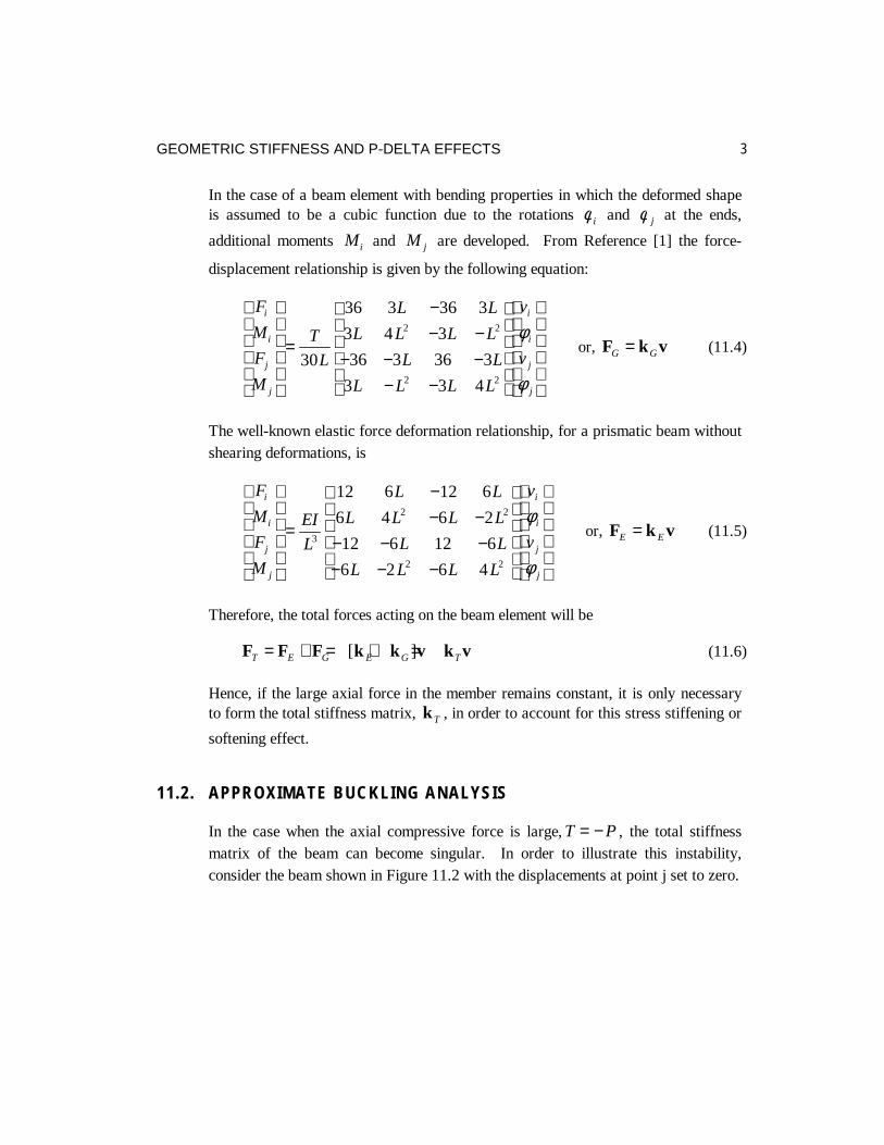
In the case of a beam element with bending properties in which the deformed shapeis assumed to be a cubic function due to the rotations φ i and φ j at the ends,
additional moments Mi and M j are developed. From Reference [1] the force-
displacement relationship is given by the following equation:
F
M
F
M
T
L
L L
L L L L
L L
L L L L
v
v
i
i
j
j
i
i
j
j
=
−− −
− − −− −
30
36 3 36 3
3 4 3
36 3 36 3
3 3 4
2 2
2 2
φ
φ
or, F k vG G= (11.4)
The well-known elastic force deformation relationship, for a prismatic beam withoutshearing deformations, is
F
M
F
M
EI
L
L L
L L L L
L L
L L L L
v
v
i
i
j
j
i
i
j
j
=
−− −
− − −− − −
3
2 2
2 2
12 6 12 6
6 4 6 2
12 6 12 6
6 2 6 4
φ
φ
or, F k vE E= (11.5)
Therefore, the total forces acting on the beam element will be
F F F k k v k vT E G E G T= + = + =[ ] (11.6)
Hence, if the large axial force in the member remains constant, it is only necessaryto form the total stiffness matrix, kT , in order to account for this stress stiffening or
softening effect.
11.2. APPROXIMATE BUCKLING ANALYSIS
In the case when the axial compressive force is large, T P= − , the total stiffnessmatrix of the beam can become singular. In order to illustrate this instability,consider the beam shown in Figure 11.2 with the displacements at point j set to zero.

DYNAMIC ANALYSIS OF STRUCTURES4
L
P EIi j
Figure 11.2 Cantilever Beam Subjected to Buckling Load
From Equation (11.6) the equilibrium equations for the beam, shown in Figure 11.2,are in matrix form
12 36 6 3
6 3 4 4
0
02 2
+ ++ +
=
λ λλ λ φ
L L
L L L L
vi
i
(11.7)
Where λ = − PL
EI
2
30. This eigenvalue problem can be solved for the lowest root
which is
λ1 0 0858= − . or PEI
Lcr = 2 57 2. (11.8)
The well-known exact Euler buckling load for the cantilever beam is given by
PEI
L
EI
Lcr = =π 2
2 242 47. (11.9)
Therefore, the approximate solution Equation (11.8), which is based on a cubicshape, is within five percent of the exact solution.
If the straight line approximation is used, given by Equation (11.3), an approximate
buckling load of 30 2.EI
L is obtained. This is still a reasonable approximation.

GEOMETRIC STIFFNESS AND P-DELTA EFFECTS 5
11.3. P-DELTA ANALYSIS OF BUILDINGS
The use of the geometric stiffness matrix is a general approach to include secondaryeffects in the static and dynamic analysis of all types of structural systems.However, in Civil Structural Engineering it is commonly referred to as P-DeltaAnalysis that is based on a more physical approach. For example, in buildinganalysis the lateral movement of a story mass to a deformed position generatessecond-order overturning moments. This second-order behavior has been termed theP-Delta effect since the additional overturning moments on the building are equal tothe sum of story weights “P” times the lateral displacements “Delta”.
Many techniques have been proposed for evaluating this second-order behavior.Rutenberg [2] summarized the publications on this topic and presents a simplifiedmethod to include these second-order effects. Some methods consider the problemas one of geometric non-linearity and propose iterative solution techniques that canbe numerically inefficient. Also, these iterative methods are not appropriate fordynamic analysis where the P-Delta effect causes lengthening of the periods ofvibration. The equations presented in this section are not new. However, the simpleapproach used in their derivation should add physical insight to the understanding ofP-Delta behavior in buildings [3].
The P-Delta problem can be linearized and the solution to the problem obtaineddirectly and exactly, without iteration, in building type structures where the weightof the structure is constant during lateral motions and the overall structuraldisplacements can be assumed to be small compared to the structural dimensions.Furthermore, the additional numerical effort required is negligible.
The method does not require iteration since the total axial force at a story level isequal to the weight of the building above that level and does not change during theapplication of lateral loads. Therefore, the sum of the column of geometric stiffnessterms associated with the lateral loads cancels and only the axial forces due to theweight of the structure need be included in the evaluation of the geometric stiffnessterms for the complete building.
The effects of P-Delta are implemented in the basic analytical formulation thatcauses the effects to be consistently included in both static and dynamic analyses.The structural displacements and the mode shapes and frequencies thus obtained
DYNAMIC ANALYSIS OF STRUCTURES6
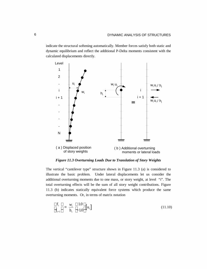
indicate the structural softening automatically. Member forces satisfy both static anddynamic equilibrium and reflect the additional P-Delta moments consistent with thecalculated displacements directly.
( a ) Displaced positionof story weights
( b ) Additional overturningmoments or lateral loads
ui ui
Level
1
2
-
i i
i + 1 i + 1
-
-
-
-
N
wi
wi
hi
uiwi hi/
uiwi hi/
Figure 11.3 Overturning Loads Due to Translation of Story Weights
The vertical “cantilever type” structure shown in Figure 11.3 (a) is considered toillustrate the basic problem. Under lateral displacements let us consider theadditional overturning moments due to one mass, or story weight, at level “i”. Thetotal overturning effects will be the sum of all story weight contributions. Figure11.3 (b) indicates statically equivalent force systems which produce the sameoverturning moments. Or, in terms of matrix notation
[ ]f
f hui
i+1
i
ii
=
−
w 10
10
.
.(11.10)

GEOMETRIC STIFFNESS AND P-DELTA EFFECTS 7
The lateral forces shown in Figure 11.3 (b) can be evaluated for all stories andadded to the external loads on the structure. The resulting lateral equilibriumequation of the structure is
Ku F Lu= + (11.11)
where K is the lateral stiffness matrix with respect to the lateral storydisplacements u. The vector F represents the known lateral loads and L is a matrixthat contains w / hi i factors. Equation (11.11) can be rewritten in the form
K u F* = (11.12)
where K K L* = −
Equation (11.12) can be solved directly for the lateral displacements. If internal memberforces are evaluated from these displacements, consistent with the linear theory used, itwill be found that equilibrium with respect to the deformed position has been obtained.One minor problem exists with the solution of Equation (11.12) - the matrix K* is notsymmetric. However, it can be made symmetric by replacing the lateral loads shown inFigure 11.3 (b) with another statically equivalent load system.
From simple statics the total contribution to overturning, due to the relative storydisplacement “u - ui i+1 ”, can be written as
f
fW
h
u
ui
i+1
i
i
i
i+1
=
−−
10 10
10 10
. .
. .(11.13)
where Wi is the total dead load weight above story “i”. The L matrix is nowsymmetrical and no special non-symmetric equation solver is required.
It is of significant interest to note that Equation (11.13) is the exact form of the“geometric stiffness”, Equation (11.3), for a column including axial force effectsonly. Therefore, the physical development given here is completely equivalent to themore theoretical approach normally used to formulate the incremental stiffness innonlinear structural analysis.
DYNAMIC ANALYSIS OF STRUCTURES8
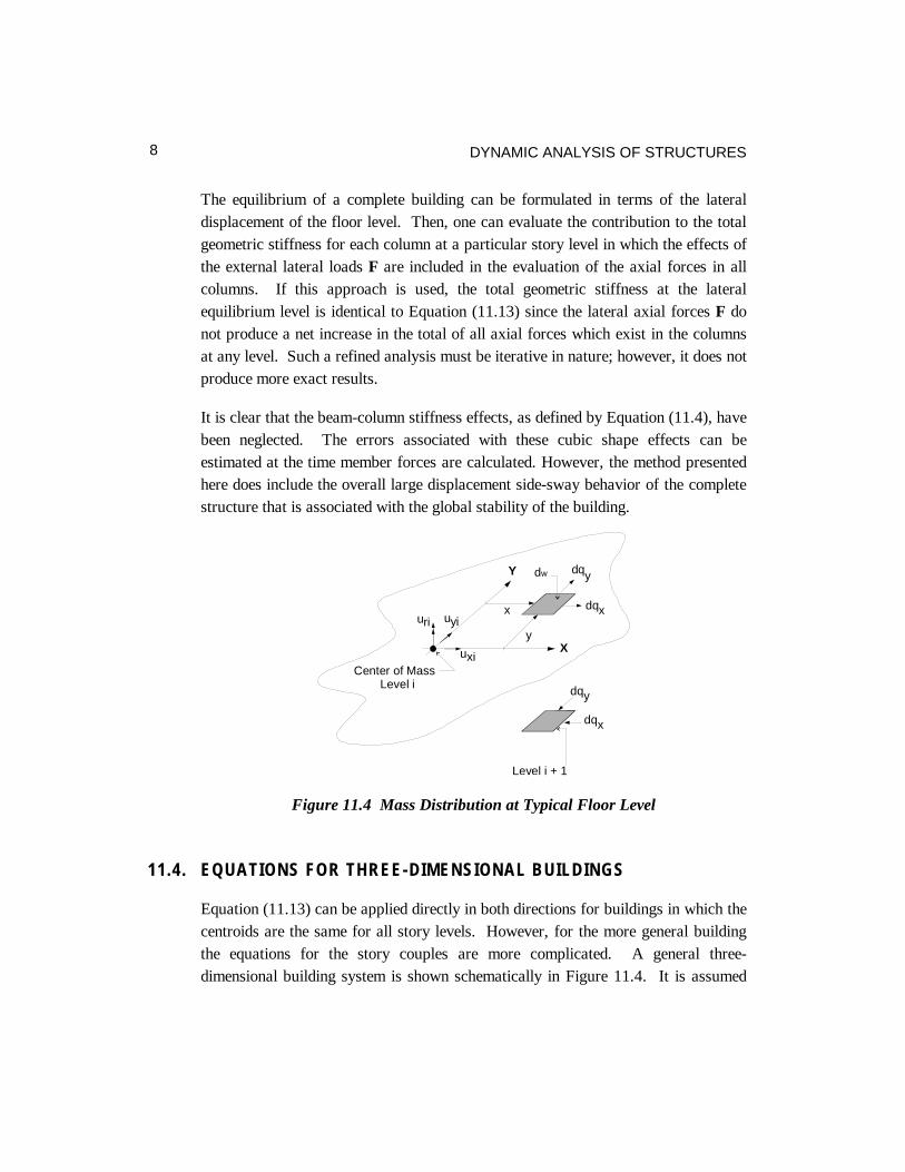
The equilibrium of a complete building can be formulated in terms of the lateraldisplacement of the floor level. Then, one can evaluate the contribution to the totalgeometric stiffness for each column at a particular story level in which the effects ofthe external lateral loads F are included in the evaluation of the axial forces in allcolumns. If this approach is used, the total geometric stiffness at the lateralequilibrium level is identical to Equation (11.13) since the lateral axial forces F donot produce a net increase in the total of all axial forces which exist in the columnsat any level. Such a refined analysis must be iterative in nature; however, it does notproduce more exact results.
It is clear that the beam-column stiffness effects, as defined by Equation (11.4), havebeen neglected. The errors associated with these cubic shape effects can beestimated at the time member forces are calculated. However, the method presentedhere does include the overall large displacement side-sway behavior of the completestructure that is associated with the global stability of the building.
Y
X
dw
Level i
x
y
Center of Mass
Level i + 1
uri uyi
uxi
dqy
dqy
dqx
dqx
Figure 11.4 Mass Distribution at Typical Floor Level
11.4. EQUATIONS FOR THREE-DIMENSIONAL BUILDINGS
Equation (11.13) can be applied directly in both directions for buildings in which thecentroids are the same for all story levels. However, for the more general buildingthe equations for the story couples are more complicated. A general three-dimensional building system is shown schematically in Figure 11.4. It is assumed
GEOMETRIC STIFFNESS AND P-DELTA EFFECTS 9
that the three dimensional building stiffness of the system has been formulated withrespect to the two lateral displacements, u uxi yi, , and rotation, uri , at the center ofmass at each story level. In addition to the overturning forces given by Equation11.13, secondary forces exist due to the distribution of the story mass over a finitefloor size.
The first step, prior to the development of the 6 by 6 geometric stiffness matrix foreach story, is to calculate the location of the center of mass and the rotationalmoment of inertia for all story levels. For a typical story “i” it is then necessary tocalculate the total weight and centroid of the structure above that level. Due to therelative displacements between story “i” and story “i + 1”, from Equation 11.13,forces must be developed to maintain equilibrium. These forces and displacementsmust then be transformed to the center of mass at both level “i” and “i + 1”.
11.5. THE MAGNITUDE OF P-DELTA EFFECTS
The comparison of the results of two analyses with and without P-Delta willillustrate the magnitude of the P-Delta effects. A well-designed building usually haswell-conditioned level by level stiffness/weight ratios. For such structures, P-Deltaeffects are usually not very significant. The changes in displacements and memberforces are less than 10%.
However, if the weight of the structure is high in proportion to the lateral stiffness ofthe structure, the contributions from the P-Delta effects are highly amplified and,under certain circumstances, can change the displacements and member forces by 25percent or more. Excessive P-Delta effects will eventually introduce singularitiesinto the solution, indicating physical structure instability. Such behavior is clearlyindicative of a poorly designed structure that is in need of additional stiffness.
An analysis of a 41-story steel building was conducted with and without P-Deltaeffects. The basic construction was braced frame and welded steel shear wall. Thebuilding was constructed in a region where the principal lateral loading is wind. Theresults are summarized in Table 11.1.

DYNAMIC ANALYSIS OF STRUCTURES10
Table 11.1. P-Delta Effects on Typical Building
Without P-Delta With P-Delta
First Mode Period (seconds) 5.33 5.52
Second Mode Period (seconds) 4.21 4.30
Third Mode Period (seconds) 4.01 4.10
Fourth Mode Period (seconds) 1.71 1.75
Wind Displacement (inches) 7.99 8.33
Since the building is relatively stiff, the P-Delta effects are minimal. Also, it isapparent that P-Delta effects are less important for higher frequencies.
11.6. P-DELTA ANALYSIS WITHOUT COMPUTER PROGRAMMODIFICATION
Many engineers are using general purpose, structural analysis programs forbuildings that cannot be easily modified to include the equations presented here.Equation 11.4 presents the form of the lateral force-displacement equations for story“i”. We note that the form of this 2 x 2 geometric stiffness matrix is the same as thestiffness matrix for a prismatic column that has zero rotations at the top and bottom.Therefore, it is possible to add “dummy columns” between story levels of thebuilding and assign appropriate properties in order to achieve the same effects as theuse of geometric stiffness [2]. The force-displacement equations of the “dummycolumn” are
−
−=
++ 1i
i
3i1i
i
u
u
11
11
h
12EIf
f(11.14)
Therefore, if the moment of inertia of the column is selected as
12E
hWI
2ii−= (11.15)
The dummy column will have the same negative stiffness values as the lineargeometric stiffness

GEOMETRIC STIFFNESS AND P-DELTA EFFECTS 11
11.7. EFFECTIVE LENGTH - K FACTORS
The solution procedure for the P-Delta effects described in this chapter has beenimplemented and verified in the ETABS program. The application of the method ofanalysis presented in this chapter should lead to the elimination of the columneffective length (K-) factors, since the P-Delta effects automatically produce therequired design moment amplifications. Also, the K-factors are approximate,complicated, and time-consuming to calculate. Building codes for concrete [4] andsteel [5] now allow explicit accounting of P-Delta effects as an alternative to themore involved and approximate methods of calculating moment magnificationfactors for most column designs.
11.8. GENERAL FORMULATION OF GEOMETRY STIFFNESS
It is relatively simple to develop the geometric stiffness matrix for any type ofdisplacement based finite element [1]. It is only necessary to add to the linear strain-displacement equations, Equation (2.3), the higher order nonlinear terms. Theselarge strain equations, in a local x-y-z reference system, are
xTyy
Tx
zyyz
xTzz
Tx
zxxz
xTyy
Tx
yxxy
zTz
zz
yTy
yy
xTx
xx
x
u
z
ux
u
z
u
x
u
y
u
z
u
y
ux
u
,,,,
,,,,
,,,,
,,
,,
,,
2
1
2
1
2
1
2
1
2
1
2
1
2
1
2
1
2
1
uuuu
uuuu
uuuu
uu
uu
uu
++∂
∂+
∂∂
=
++∂
∂+∂
∂=
++∂
∂+
∂∂
=
+∂
∂=
+∂
∂=
+∂
∂=
γ
γ
γ
ε
ε
ε
(11.16)
The nonlinear terms are the product of matrices that are defined as

DYNAMIC ANALYSIS OF STRUCTURES12
=
=
=
zz
zy
zx
z
yz
yy
yx
y
xz
xy
xx
x
u
u
u
u
u
u
u
u
u
,
,
,
,
,
,
,
,
,
,
,
, ,, uuu (11.17)
Equation (11.16) can be expressed in terms of the following sum of linear andnonlinear components:
NL ddd += (11.18)
These strain-displacement equations, written in terms of engineering strains and inmatrix notation, are identical to the classical Green-Lagrange strains. This is oftenreferred to as the total Lagrangian approach in which the strains are computed withrespect to the original reference system and the large rigid-body rotation is exact.
If the initial stresses are large, the potential energy of the structure must be modifiedby the addition of the following term:
The initial stresses are defined as
[ ] 00 yzxzxyzzyyxxT σσσσσσ=s (11.19)
Equation (11.19) can be written in the following form:
[ ] dVdV T
z
y
x
zzzyzx
yzyyyx
xzxyxxT
z
Ty
Tx ∫∫ =
=Ω gSg
u
u
u
sss
sss
sss
uuu2
1
2
1
,
,
,
,,,σ (11.20)
The 3 by 3 initial stress matrices are of the following form:
000
0
00
=
ij
ij
ij
ij
σσ
σs (11.21)
Using the same shape functions as used to form the element stiffness matrix, thederivatives of the displacements can be written as
Gug = (11.22)
GEOMETRIC STIFFNESS AND P-DELTA EFFECTS 13
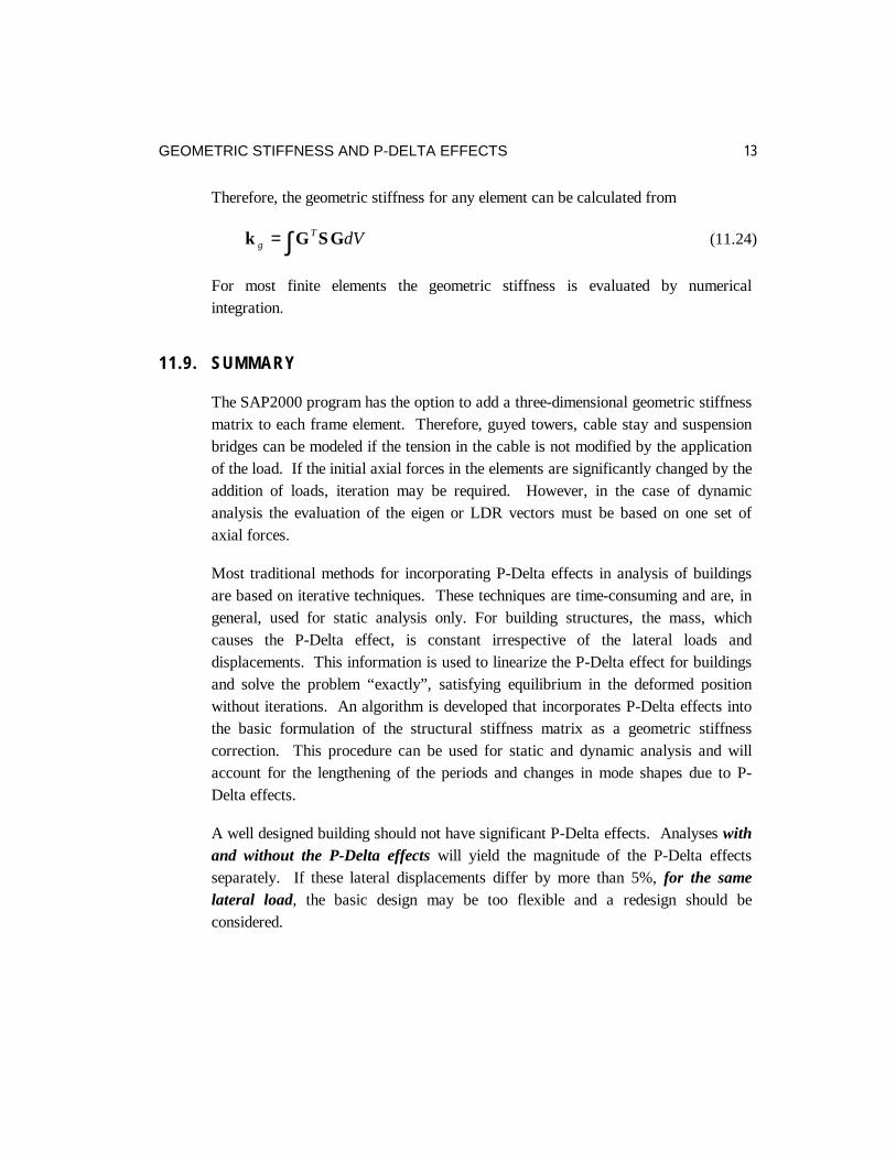
Therefore, the geometric stiffness for any element can be calculated from
dVTg GSGk ∫= (11.24)
For most finite elements the geometric stiffness is evaluated by numericalintegration.
11.9. SUMMARY
The SAP2000 program has the option to add a three-dimensional geometric stiffnessmatrix to each frame element. Therefore, guyed towers, cable stay and suspensionbridges can be modeled if the tension in the cable is not modified by the applicationof the load. If the initial axial forces in the elements are significantly changed by theaddition of loads, iteration may be required. However, in the case of dynamicanalysis the evaluation of the eigen or LDR vectors must be based on one set ofaxial forces.
Most traditional methods for incorporating P-Delta effects in analysis of buildingsare based on iterative techniques. These techniques are time-consuming and are, ingeneral, used for static analysis only. For building structures, the mass, whichcauses the P-Delta effect, is constant irrespective of the lateral loads anddisplacements. This information is used to linearize the P-Delta effect for buildingsand solve the problem “exactly”, satisfying equilibrium in the deformed positionwithout iterations. An algorithm is developed that incorporates P-Delta effects intothe basic formulation of the structural stiffness matrix as a geometric stiffnesscorrection. This procedure can be used for static and dynamic analysis and willaccount for the lengthening of the periods and changes in mode shapes due to P-Delta effects.
A well designed building should not have significant P-Delta effects. Analyses withand without the P-Delta effects will yield the magnitude of the P-Delta effectsseparately. If these lateral displacements differ by more than 5%, for the samelateral load, the basic design may be too flexible and a redesign should beconsidered.

DYNAMIC ANALYSIS OF STRUCTURES14
The current SEAOC Blue Book states “the drift ratio of 0.02/RW serves to define thethreshold of deformation beyond which there may be significant P-Delta effects”.Clearly, if one includes P-Delta effects in all analyses one can disregard thisstatement. If the loads acting on the structure have been reduced by a ductilityfactor RW, however, the P-Delta effects should be amplified by RW in order to reflectultimate load behavior. This can be automatically included in a computer programby using a multiplication factor for the geometric stiffness terms.
It is possible to calculate geometric stiffness matrices for all types of finite elements.The same shape functions used in the development of elastic stiffness matrices areused in the calculation of the geometric stiffness matrix.
11.10. REFERENCES
1. R. D. Cook., D. S. Malkus and M. E. Plesha, Concepts and Applications ofFinite Element Analysis, Third Edition, John Wiley & Sons, Inc, ISBN 0-471-84788-7, 1989.
2. A. Rutenberg, "Simplified P-Delta Analysis for Asymmetric Structures," ASCEJournal of the Structural Division, Vol. 108, No. 9, Sept. 1982.
3. E. L. Wilson and A. Habibullah, "Static and Dynamic Analysis of Multi-StoryBuildings Including P-Delta Effects," Earthquake Spectra, EarthquakeEngineering Research Institute, Vol. 3, No.3, May 1987.
4. Building Code Requirements for Reinforced Concrete (ACI 318-95) andCommentary (ACI 318R-95), American Concrete Institute, Farmington Hills,Michigan, 1995.
5. Load and Resistance Factor Design Specification for Structural SteelBuildings, American Institute of Steel Construction, Inc., Chicago, Illinois,December, 1993.