Geometric parameter optimization of magneto-rheological ...
9
ORIGINAL ARTICLE Open Access Geometric parameter optimization of magneto-rheological damper using design of experiment technique S K Mangal * and Ashwani Kumar Abstract Background: Magneto-rheological (MR) damper is one of the most promising semi-active devices. The MR dampers offer a reliability of a passive system yet maintain the versatility and adaptability of the fully active control devices. Methods: In this paper, an optimization process is developed to optimize the geometrical parameters of an MR damper using finite element method (FEM) coupled with Taguchi approach which is rarely available in the literature. The damping force of the MR damper is selected as an objective function. To achieve this objective, 18 FEM models, based on Taguchi orthogonal array, are developed on ANSYS platform. Results: These results have been analyzed by using the design of experiment (DoE) methodology and an optimized solution is then arrived. The optimal solution is validated experimentally as well as through FEM for 95% confidence level. These results are found to be in good agreement with each other. Conclusions: This paper establishes that numerical technique results, e.g., FEM, can be used over the real experimental results for the geometric parameter optimization of an MR damper. The proposed methodology will save time and resources for designing an optimized MR damper for automotive and other applications. Keywords: Optimization; Magneto-rheological damper; Finite element method; Taguchi technique; Design of experiment; Geometric parameters Background Smart materials are the materials having multiple tunable properties. These material properties are significantly al- tered in a controlled and reversible manner by some ex- ternal stimuli, e.g., current, electric, or magnetic fields, etc (Ashwani and Mangal 2012). Magneto rheological fluid (MRF) is one of such smart materials. The discovery of the MR fluids is credited to Jacob Rabinow in 1948 at the US National Bureau of Standard (Rabinow 1948). Excel- lent features of the MRF technology, e.g., fast response, simple interface between electrical power input and mech- anical power output, and precise controllability, make it most attractive for many industrial applications. These features have triggered considerable research activities on the modeling and design of MR devices, e.g., dampers, valves, clutches, and brakes, etc. When this technology is employed for an automotive damper, it gives a variable damping coefficient which mainly depends on the intensity of the magnetic field induced. This makes vi- bration control/isolation effective over a wide frequency spectrum and is more useful in a real practical sense. A typical magneto-rheological damper consists of cylinder, piston, excitation coil, and the MR fluid which is en- veloped in a cylinder. The MR valves and dampers are designed analytically (Zhu et al. 2012; Wei et al. 2003) as well as using finite element method (Li and Guo 2003; Parlak et al. 2012). An analytical optimization design method is also proposed (Rosenfield and Werely 2004) for the MR valves and dampers which are based on the as- sumption of constant magnetic flux density throughout the magnetic circuit. In the analysis (Rosenfield and Werely 2004), it has been assumed that one region of the magnetic circuit does not saturate prematurely. As the valve performance not only depends on the magnetic cir- cuit but also on the geometry of the ducts through which * Correspondence: [email protected] Mechanical Engineering Department, PEC University of Technology, Chandigarh 160012, India © 2015 Mangal and Kumar; licensee Springer. This is an Open Access article distributed under the terms of the Creative Commons Attribution License (http://creativecommons.org/licenses/by/4.0), which permits unrestricted use, distribution, and reproduction in any medium, provided the original work is properly credited. Mangal and Kumar International Journal of Mechanical and Materials Engineering (2015) 10:4 DOI 10.1186/s40712-015-0031-1
Transcript of Geometric parameter optimization of magneto-rheological ...
Mangal and Kumar International Journal of Mechanicaland Materials Engineering (2015) 10:4 DOI 10.1186/s40712-015-0031-1
ORIGINAL ARTICLE Open Access
Geometric parameter optimization ofmagneto-rheological damper using design ofexperiment techniqueS K Mangal* and Ashwani Kumar
Abstract
Background: Magneto-rheological (MR) damper is one of the most promising semi-active devices. The MR dampersoffer a reliability of a passive system yet maintain the versatility and adaptability of the fully active control devices.
Methods: In this paper, an optimization process is developed to optimize the geometrical parameters of an MRdamper using finite element method (FEM) coupled with Taguchi approach which is rarely available in the literature.The damping force of the MR damper is selected as an objective function. To achieve this objective, 18 FEM models,based on Taguchi orthogonal array, are developed on ANSYS platform.
Results: These results have been analyzed by using the design of experiment (DoE) methodology and an optimizedsolution is then arrived. The optimal solution is validated experimentally as well as through FEM for 95% confidencelevel. These results are found to be in good agreement with each other.
Conclusions: This paper establishes that numerical technique results, e.g., FEM, can be used over the real experimentalresults for the geometric parameter optimization of an MR damper. The proposed methodology will save time andresources for designing an optimized MR damper for automotive and other applications.
Keywords: Optimization; Magneto-rheological damper; Finite element method; Taguchi technique; Design ofexperiment; Geometric parameters
BackgroundSmart materials are the materials having multiple tunableproperties. These material properties are significantly al-tered in a controlled and reversible manner by some ex-ternal stimuli, e.g., current, electric, or magnetic fields, etc(Ashwani and Mangal 2012). Magneto rheological fluid(MRF) is one of such smart materials. The discovery ofthe MR fluids is credited to Jacob Rabinow in 1948 at theUS National Bureau of Standard (Rabinow 1948). Excel-lent features of the MRF technology, e.g., fast response,simple interface between electrical power input and mech-anical power output, and precise controllability, make itmost attractive for many industrial applications. Thesefeatures have triggered considerable research activitieson the modeling and design of MR devices, e.g.,dampers, valves, clutches, and brakes, etc. When this
* Correspondence: [email protected] Engineering Department, PEC University of Technology,Chandigarh 160012, India
© 2015 Mangal and Kumar; licensee Springer. TCommons Attribution License (http://creativecoreproduction in any medium, provided the orig
technology is employed for an automotive damper, it givesa variable damping coefficient which mainly depends onthe intensity of the magnetic field induced. This makes vi-bration control/isolation effective over a wide frequencyspectrum and is more useful in a real practical sense. Atypical magneto-rheological damper consists of cylinder,piston, excitation coil, and the MR fluid which is en-veloped in a cylinder. The MR valves and dampers aredesigned analytically (Zhu et al. 2012; Wei et al. 2003) aswell as using finite element method (Li and Guo 2003;Parlak et al. 2012). An analytical optimization designmethod is also proposed (Rosenfield and Werely 2004) forthe MR valves and dampers which are based on the as-sumption of constant magnetic flux density throughoutthe magnetic circuit. In the analysis (Rosenfield andWerely 2004), it has been assumed that one region of themagnetic circuit does not saturate prematurely. As thevalve performance not only depends on the magnetic cir-cuit but also on the geometry of the ducts through which
his is an Open Access article distributed under the terms of the Creativemmons.org/licenses/by/4.0), which permits unrestricted use, distribution, andinal work is properly credited.

Mangal and Kumar International Journal of Mechanical and Materials Engineering (2015) 10:4 Page 2 of 9
the MR fluid passes, the above assumption has led to asub-optimal solution. One, thus, can say that the re-search on optimal design of an MR damper is still in itsnascent age.The objective of this paper is to optimize geometric pa-
rameters of an MR damper to have its optimized dampingperformance. The optimization of the MR damper is basedon the design of experiment (using Taguchi methodology)and finite element method which is rarely available in theliterature. Based on the critical literature survey, four geo-metric parameters of the MR damper, which influences thedamping force the most are selected. Based on Taguchimethodology, L18 orthogonal array (OA) is selected. As theauthors have found that the FEM results were in goodagreement with the experimental results (Ashwani Kumaret al. 2014; Ashwani and Mangal 2014), the response par-ameter, i.e., damping force of the MR damper as obtainableby the FEM, is employed in the Taguchi technique in placeof the real experimental results. Further, the use of theFEM-based modeling saves the cost of optimization pro-cess. The response parameter of these models is analyzedin the ANOVA to get an optimized solution. The confirm-ation experiment of the optimized MR damper is per-formed by fabricating the MR damper with optimizedgeometric parameters as obtained by design of experiment(DoE) analysis. The field-dependent damping force for theoptimized damper is determined by the FEM (on ANSYSplatform) as well as experimentally. The confirmation ex-periment on the optimized MR damper is found to havegood conformity with the optimal design results for 95%confidence level. The main contribution of this paper is toestablish the approach of optimization of the MR dampergeometry with the sole objective of maximizing the damp-ing force using DoE technique and finite element analysis.The optimization process proposed here has used the nu-merical technique results, e.g., FEM over the real experi-mental results in the optimization process and saved timeand resources for designing of an optimized MR damper.
MethodsModeling and experimental studies of an MR damperWhile modeling of an MR damper, it is assumed thatthe magnetic loop is formed only in the magnetic mater-ial and magnetic flux leakage is negligible in it. Accord-ing to the magnetic Ohm’s law, the magnetic circuitparameters are magnetic reluctance, Ri (AT/WB), mag-netic flux, φ (WB), and magnetic potential, F (AT). Theirrelationship is given as
F ¼ Ri φ; ð1Þ
where F is magnetic potential and is also given as NI,where N is the number of coil turns and I is the current
passed through the coil. The magnetic reluctance, Ri, isgiven as
Ri ¼ Li
μiAi; ð2Þ
where the Li, Ai, and μi are the length (mean path ofmagnetic flux lines in the component), cross sectionalarea of the component, and permeability of ith elementof the magnetic flux path, respectively. The magneticflux, φ, and magnetic flux density, B, are given by:
φ ¼ NIRT
; B ¼ φ
A; ð3Þ
where the RT is the total reluctance of the magneticpath. According to the structural design, one gets a typ-ical magnetic loop for the MR damper (Figure 1). Aftera critical literature survey, the various dimensions of anMR damper prototype are selected and are shown inTable 1. The magnetic flux density (B) of the designedmagnetic circuit is calculated for different current levelsfor the MR damper.For the FEM modeling, the MR damper is an axi-
symmetric solid subjected to axi-symmetric loading. A 2-D FEM modeling is, thus, selected for its analysis throughthe ANSYS platform. The piston, MR fluid gap, and thecylinder are assumed to be stationary component, and itcompletes the magnetic circuit around the coil. In themodeling, 350 turns are wrapped over the piston to makeit electromagnet and to calculate the magnetic flux. TheMR damper is modeled on the ANSYS platform to cal-culate its magnetic flux density in the clearance space ofthe damper. The relationship between the magnetic fluxdensity (B) and yield shear stress (τy) for the LORD MRF-122EG (www.lord.com) fluid is to be determined to evalu-ate the damping force. To determine this relationship,data is extracted from the technical graphs supplied bythe LORD® Corp. Inc., Cary, USA (www.lord.com). Usingcurve fitting techniques of MATLAB software, relation-ship between yield shear stress (τy) and magnetic fluxdensity (B) for the fluid is determined. The correspondingcubical polynomial as obtained by the MATLAB softwareis given as
τy ¼ 6:9� 102� �þ 4� 104
� �B− 1� 105� �
B2
þ 9:1� 104� �
B3 ð4Þ
Thereafter, using the magnetic flux density as deter-mined in the above modeling, the corresponding valuesof the yield shear stress is thus determined.According to Bingham plastic model, based on the
plate modeling (Carlson et al. 1995; Zhao-Dong 2012;Engineering Note-Designing with MR Fluids), thetotal damping force, FD, is the sum of an induced

Figure 1 Typical magnetic loop of an MR damper.
Mangal and Kumar International Journal of Mechanical and Materials Engineering (2015) 10:4 Page 3 of 9
yield stress component, Fτ, and viscous components,Fη, is given as
FD ¼ Fτ þ Fη ¼ 2:07þ 12Qη
12Qηþ 0:4wh2τy
!τyLAp
hsgn vð Þ
þ 1þ whv2Q
� �12ηQLtAp
wh3;
ð5Þwhere
Q ¼ Ap � v ð6Þ
Ap ¼ π
4D2−d2
o
� �; ð7Þ
Table 1 Dimensions of a prototype MR damper
Serialnumber
Parameter Dimensions(mm)
1 Pole length (L) 23
2 Distance between the poles (ℓ) 22
3 Radius of the piston (R) 23
4 Piston rod radius (r) 06
5 Radial distance from piston rod to coil width (H) 07
6 Clearance between piston and cylinder (h) 01
7 Thickness of the cylinder (t) 08
(Ashwani Kumar et al. 2014).
where Q is the volumetric flow rate, Ap is the effectivecross-sectional area of piston, D is the diameter of the pis-ton, d0 is the diameter of the piston rod, υ is the pistonvelocity, τy is the yield shear strength of the MR fluid, η isthe off-state (no magnetic field) viscosity of the MR fluid,L is the effective axial pole length, h is the gap betweenpiston and cylinder, Lt is the total axial pole length, w isthe mean circumference of the damper’s annular flowpath, and sgn(υ) is used to consider the reciprocating mo-tion of the piston. Total damping force of the FEM modelis thus calculated using Equation 5 and is tabulated quan-titatively in the second column of Table 2.Based on the above modeling (Ashwani Kumar et al.
2014; Ashwani and Mangal 2014), an MR damper is fab-ricated of the dimensions as listed in Table 1. The LORDMRF-122EG (www.lord.com) MR fluid is used in thefabricated damper for evaluating its performance (AshwaniKumar et al. 2014). The input current supplied to the MRdamper is varied using Wonder Box kit provided byLORD® Corp. Inc., Cary, USA (www.lord.com). The ex-perimental damping force for different input currents asexperienced by the damper is tabulated in the third col-umn of Table 2. These results are found to be matchingwell with the FEM results.
Results and discussionScheme of experiments and optimizationA design based on Taguchi methodology is developedwith the objective of maximizing the damping force of
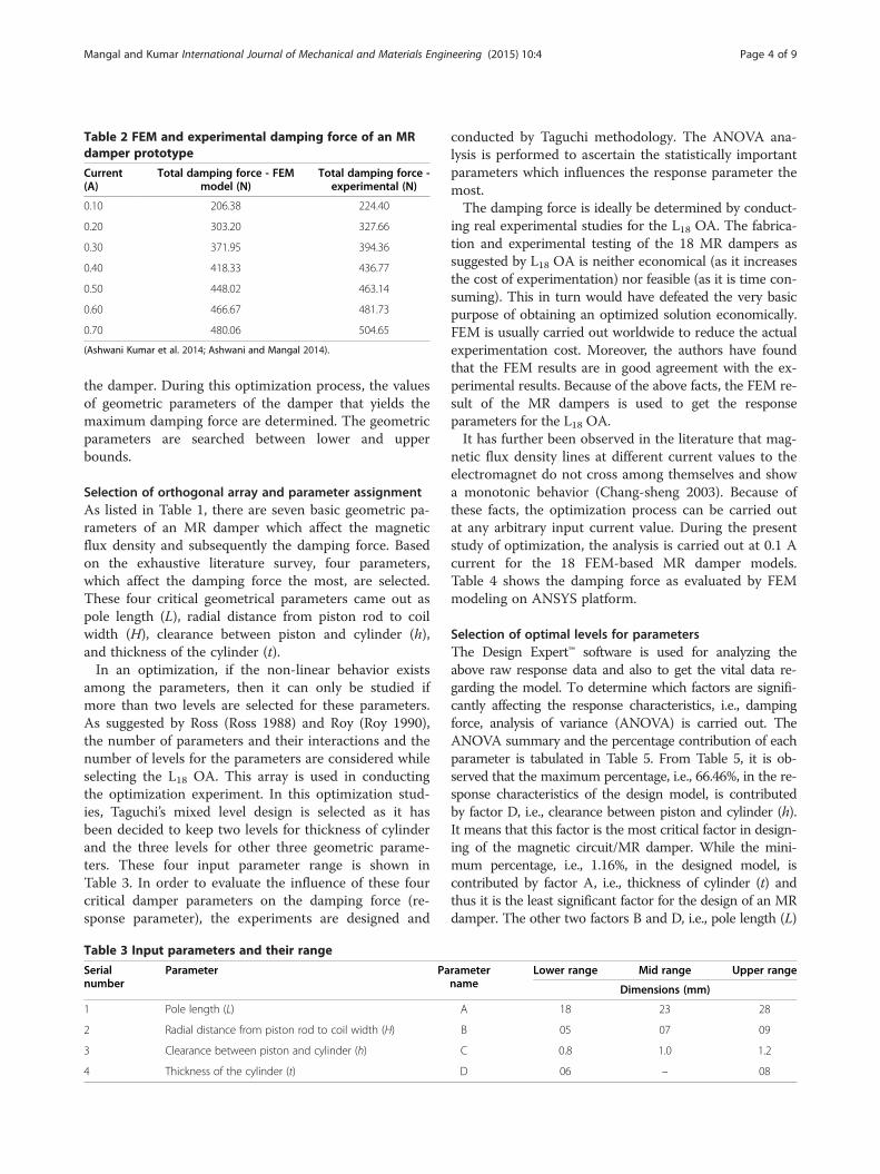
Table 2 FEM and experimental damping force of an MRdamper prototype
Current(A)
Total damping force - FEMmodel (N)
Total damping force -experimental (N)
0.10 206.38 224.40
0.20 303.20 327.66
0.30 371.95 394.36
0.40 418.33 436.77
0.50 448.02 463.14
0.60 466.67 481.73
0.70 480.06 504.65
(Ashwani Kumar et al. 2014; Ashwani and Mangal 2014).
Mangal and Kumar International Journal of Mechanical and Materials Engineering (2015) 10:4 Page 4 of 9
the damper. During this optimization process, the valuesof geometric parameters of the damper that yields themaximum damping force are determined. The geometricparameters are searched between lower and upperbounds.
Selection of orthogonal array and parameter assignmentAs listed in Table 1, there are seven basic geometric pa-rameters of an MR damper which affect the magneticflux density and subsequently the damping force. Basedon the exhaustive literature survey, four parameters,which affect the damping force the most, are selected.These four critical geometrical parameters came out aspole length (L), radial distance from piston rod to coilwidth (H), clearance between piston and cylinder (h),and thickness of the cylinder (t).In an optimization, if the non-linear behavior exists
among the parameters, then it can only be studied ifmore than two levels are selected for these parameters.As suggested by Ross (Ross 1988) and Roy (Roy 1990),the number of parameters and their interactions and thenumber of levels for the parameters are considered whileselecting the L18 OA. This array is used in conductingthe optimization experiment. In this optimization stud-ies, Taguchi’s mixed level design is selected as it hasbeen decided to keep two levels for thickness of cylinderand the three levels for other three geometric parame-ters. These four input parameter range is shown inTable 3. In order to evaluate the influence of these fourcritical damper parameters on the damping force (re-sponse parameter), the experiments are designed and
Table 3 Input parameters and their range
Serialnumber
Parameter Pa
1 Pole length (L)
2 Radial distance from piston rod to coil width (H)
3 Clearance between piston and cylinder (h)
4 Thickness of the cylinder (t)
conducted by Taguchi methodology. The ANOVA ana-lysis is performed to ascertain the statistically importantparameters which influences the response parameter themost.The damping force is ideally be determined by conduct-
ing real experimental studies for the L18 OA. The fabrica-tion and experimental testing of the 18 MR dampers assuggested by L18 OA is neither economical (as it increasesthe cost of experimentation) nor feasible (as it is time con-suming). This in turn would have defeated the very basicpurpose of obtaining an optimized solution economically.FEM is usually carried out worldwide to reduce the actualexperimentation cost. Moreover, the authors have foundthat the FEM results are in good agreement with the ex-perimental results. Because of the above facts, the FEM re-sult of the MR dampers is used to get the responseparameters for the L18 OA.It has further been observed in the literature that mag-
netic flux density lines at different current values to theelectromagnet do not cross among themselves and showa monotonic behavior (Chang-sheng 2003). Because ofthese facts, the optimization process can be carried outat any arbitrary input current value. During the presentstudy of optimization, the analysis is carried out at 0.1 Acurrent for the 18 FEM-based MR damper models.Table 4 shows the damping force as evaluated by FEMmodeling on ANSYS platform.
Selection of optimal levels for parametersThe Design Expert™ software is used for analyzing theabove raw response data and also to get the vital data re-garding the model. To determine which factors are signifi-cantly affecting the response characteristics, i.e., dampingforce, analysis of variance (ANOVA) is carried out. TheANOVA summary and the percentage contribution of eachparameter is tabulated in Table 5. From Table 5, it is ob-served that the maximum percentage, i.e., 66.46%, in the re-sponse characteristics of the design model, is contributedby factor D, i.e., clearance between piston and cylinder (h).It means that this factor is the most critical factor in design-ing of the magnetic circuit/MR damper. While the mini-mum percentage, i.e., 1.16%, in the designed model, iscontributed by factor A, i.e., thickness of cylinder (t) andthus it is the least significant factor for the design of an MRdamper. The other two factors B and D, i.e., pole length (L)
rametername
Lower range Mid range Upper range
Dimensions (mm)
A 18 23 28
B 05 07 09
C 0.8 1.0 1.2
D 06 – 08
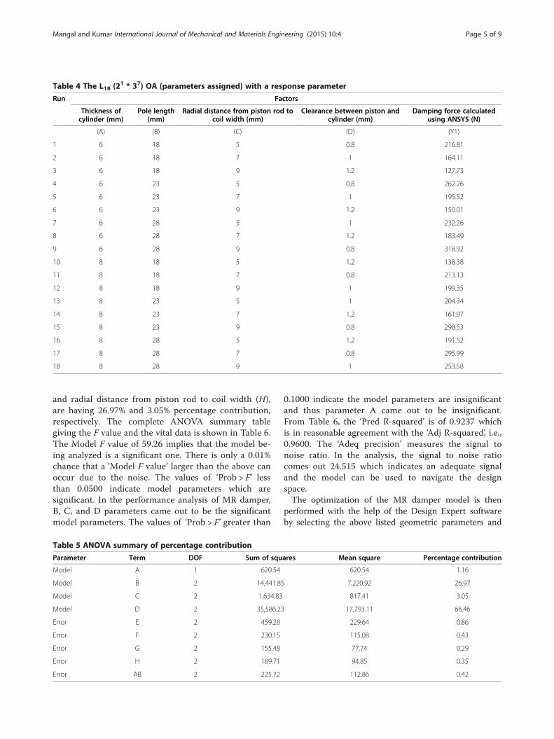
Table 4 The L18 (21 * 37) OA (parameters assigned) with a response parameter
Run Factors
Thickness ofcylinder (mm)
Pole length(mm)
Radial distance from piston rod tocoil width (mm)
Clearance between piston andcylinder (mm)
Damping force calculatedusing ANSYS (N)
(A) (B) (C) (D) (Y1)
1 6 18 5 0.8 216.81
2 6 18 7 1 164.11
3 6 18 9 1.2 127.73
4 6 23 5 0.8 262.26
5 6 23 7 1 195.52
6 6 23 9 1.2 150.01
7 6 28 5 1 232.26
8 6 28 7 1.2 183.49
9 6 28 9 0.8 318.92
10 8 18 5 1.2 138.38
11 8 18 7 0.8 213.13
12 8 18 9 1 199.35
13 8 23 5 1 204.34
14 8 23 7 1.2 161.97
15 8 23 9 0.8 298.53
16 8 28 5 1.2 191.52
17 8 28 7 0.8 295.99
18 8 28 9 1 253.58
Mangal and Kumar International Journal of Mechanical and Materials Engineering (2015) 10:4 Page 5 of 9
and radial distance from piston rod to coil width (H),are having 26.97% and 3.05% percentage contribution,respectively. The complete ANOVA summary tablegiving the F value and the vital data is shown in Table 6.The Model F value of 59.26 implies that the model be-ing analyzed is a significant one. There is only a 0.01%chance that a ‘Model F value’ larger than the above canoccur due to the noise. The values of ‘Prob > F’ lessthan 0.0500 indicate model parameters which aresignificant. In the performance analysis of MR damper,B, C, and D parameters came out to be the significantmodel parameters. The values of ‘Prob > F’ greater than
Table 5 ANOVA summary of percentage contribution
Parameter Term DOF Sum of squ
Model A 1 620.54
Model B 2 14,441.85
Model C 2 1,634.83
Model D 2 35,586.23
Error E 2 459.28
Error F 2 230.15
Error G 2 155.48
Error H 2 189.71
Error AB 2 225.72
0.1000 indicate the model parameters are insignificantand thus parameter A came out to be insignificant.From Table 6, the ‘Pred R-squared’ is of 0.9237 whichis in reasonable agreement with the ‘Adj R-squared’, i.e.,0.9600. The ‘Adeq precision’ measures the signal tonoise ratio. In the analysis, the signal to noise ratiocomes out 24.515 which indicates an adequate signaland the model can be used to navigate the designspace.The optimization of the MR damper model is then
performed with the help of the Design Expert softwareby selecting the above listed geometric parameters and
ares Mean square Percentage contribution
620.54 1.16
7,220.92 26.97
817.41 3.05
17,793.11 66.46
229.64 0.86
115.08 0.43
77.74 0.29
94.85 0.35
112.86 0.42
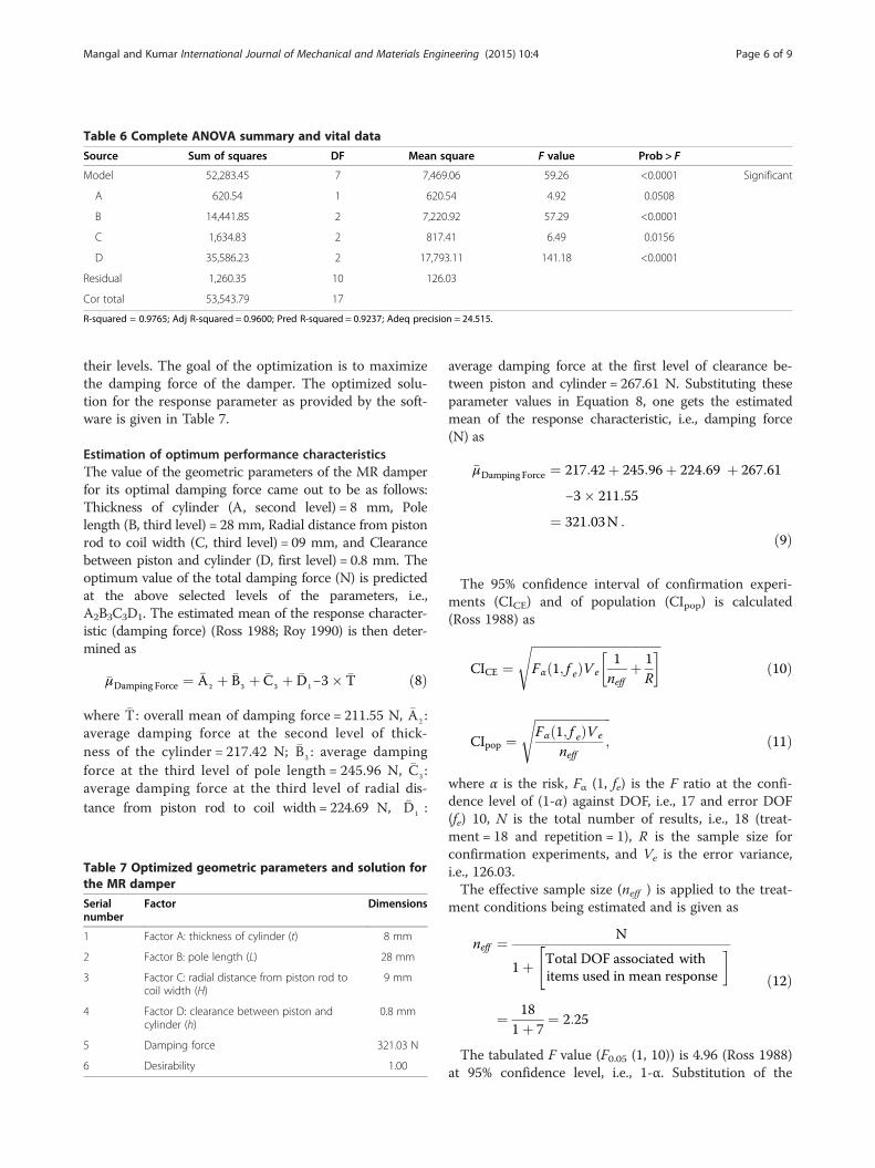
Table 6 Complete ANOVA summary and vital data
Source Sum of squares DF Mean square F value Prob > F
Model 52,283.45 7 7,469.06 59.26 <0.0001 Significant
A 620.54 1 620.54 4.92 0.0508
B 14,441.85 2 7,220.92 57.29 <0.0001
C 1,634.83 2 817.41 6.49 0.0156
D 35,586.23 2 17,793.11 141.18 <0.0001
Residual 1,260.35 10 126.03
Cor total 53,543.79 17
R-squared = 0.9765; Adj R-squared = 0.9600; Pred R-squared = 0.9237; Adeq precision = 24.515.
Mangal and Kumar International Journal of Mechanical and Materials Engineering (2015) 10:4 Page 6 of 9
their levels. The goal of the optimization is to maximizethe damping force of the damper. The optimized solu-tion for the response parameter as provided by the soft-ware is given in Table 7.
Estimation of optimum performance characteristicsThe value of the geometric parameters of the MR damperfor its optimal damping force came out to be as follows:Thickness of cylinder (A, second level) = 8 mm, Polelength (B, third level) = 28 mm, Radial distance from pistonrod to coil width (C, third level) = 09 mm, and Clearancebetween piston and cylinder (D, first level) = 0.8 mm. Theoptimum value of the total damping force (N) is predictedat the above selected levels of the parameters, i.e.,A2B3C3D1. The estimated mean of the response character-istic (damping force) (Ross 1988; Roy 1990) is then deter-mined as
�μDamping Force ¼ �A2 þ �B3 þ �C3 þ �D1−3� �T ð8Þ
where �T: overall mean of damping force = 211.55 N, �A2 :average damping force at the second level of thick-ness of the cylinder = 217.42 N; �B3 : average dampingforce at the third level of pole length = 245.96 N, �C3 :average damping force at the third level of radial dis-tance from piston rod to coil width = 224.69 N, �D1 :
Table 7 Optimized geometric parameters and solution forthe MR damper
Serialnumber
Factor Dimensions
1 Factor A: thickness of cylinder (t) 8 mm
2 Factor B: pole length (L) 28 mm
3 Factor C: radial distance from piston rod tocoil width (H)
9 mm
4 Factor D: clearance between piston andcylinder (h)
0.8 mm
5 Damping force 321.03 N
6 Desirability 1.00
average damping force at the first level of clearance be-tween piston and cylinder = 267.61 N. Substituting theseparameter values in Equation 8, one gets the estimatedmean of the response characteristic, i.e., damping force(N) as
�μDamping Force ¼ 217:42þ 245:96þ 224:69 þ 267:61
−3� 211:55
¼ 321:03N :
ð9Þ
The 95% confidence interval of confirmation experi-ments (CICE) and of population (CIpop) is calculated(Ross 1988) as
CICE ¼ffiffiffiffiffiffiffiffiffiffiffiffiffiffiffiffiffiffiffiffiffiffiffiffiffiffiffiffiffiffiffiffiffiffiffiffiffiffiffiffiffiffiffiFα 1; f eð ÞVe
1neff
þ 1R
� �sð10Þ
CIpop ¼ffiffiffiffiffiffiffiffiffiffiffiffiffiffiffiffiffiffiffiffiffiffiffiffiffiFα 1; f eð ÞVe
neff;
sð11Þ
where α is the risk, Fα (1, fe) is the F ratio at the confi-dence level of (1-α) against DOF, i.e., 17 and error DOF(fe) 10, N is the total number of results, i.e., 18 (treat-ment = 18 and repetition = 1), R is the sample size forconfirmation experiments, and Ve is the error variance,i.e., 126.03.The effective sample size (neff ) is applied to the treat-
ment conditions being estimated and is given as
neff ¼ N
1þ"Total DOF associated withitems used in mean response
�
¼ 181þ 7
¼ 2:25
ð12Þ
The tabulated F value (F0.05 (1, 10)) is 4.96 (Ross 1988)at 95% confidence level, i.e., 1-α. Substitution of the

Table 8 Total damping force comparison for theoptimized MR damper
Current(A)
Total dampingforce - FEMmodel (N)
Total damping force -experimental (N)
Percentage errorof experimentalresults with
relation to FEMone
0.10 314.18 331.20 5.42
0.20 476.26 501.81 5.37
0.30 583.67 609.79 4.48
0.40 649.10 668.99 3.06
0.50 688.12 707.99 2.89
0.60 712.92 731.40 2.59
(a) (
Lid
Cylinder
Piston Rod Piston
(d(c)
Copper winding on Piston
((e)
Figure 2 The various components of the MR damper. (a) Componentsinsulator material. (c) Assembled piston and its rod with copper winding. (rod, and lid. (f) Complete assembly of the optimized MR damper.
Mangal and Kumar International Journal of Mechanical and Materials Engineering (2015) 10:4 Page 7 of 9
above values in Equations 10 and 11 gives the values forconfidence interval of confirmation experiments (CICE)and of population (CIpop) which are given as
CICE ¼ffiffiffiffiffiffiffiffiffiffiffiffiffiffiffiffiffiffiffiffiffiffiffiffiffiffiffiffiffiffiffiffiffiffiffiffiffiffiffiffiffiffiffiffiffiffiffiffiffiffi4:96� 126:03
12:25
þ 11
� �s¼ �30:05 ð13Þ
CIPOP ¼ffiffiffiffiffiffiffiffiffiffiffiffiffiffiffiffiffiffiffiffiffiffiffiffiffiffiffiffi4:96� 126:03
2:25
r¼ �16:67 ð14Þ
b)Grooved portion of piston where winding is to be done
)
Copper winding covered with cloth
f)
Assembly of MR Damper parts
of the optimized MR damper. (b) Grooved portion of piston withd) Copper winding covered with a cloth. (e) Assembly of piston, piston

0.1 0.2 0.3 0.4 0.5 0.6
300
400
500
600
700
800
Tot
al d
ampi
ng fo
rce
(N)
Current (A)
FEM Experimental
Figure 3 Total damping force comparison for optimizedMR damper.
Mangal and Kumar International Journal of Mechanical and Materials Engineering (2015) 10:4 Page 8 of 9
The predicted optimal range for the damping forcebased on confidence interval of confirmation experi-ments (CICE) is given as
μDamping Force−CICE < μDamping Force < μDamping Force þ CICE290:98 < μDamping Force < 351:07
ð15ÞThe 95% conformation interval of the predicted mean
of the damping force for confidence interval of popula-tion (CIpop) is given as
μDamping Force−CIpop < μDamping Force < μDamping Force þ CIpop304:36 < μDamping Force < 337:69
ð16Þ
Modeling of optimized MR damperAfter optimizing the significant MR damper parameters,the FEM modeling and the experimental study are per-formed and are illustrated in this section.
FEM modelingThe optimized MR damper is modeled by the FEM onANSYS platform in a similar manner as illustrated aboveand the total damping force is then determined for themodel. The total damping force is shown in the secondcolumn of Table 8.
Experimental testingBased on the optimization results, an optimized MRdamper is fabricated. The various components of the MRdamper are shown in Figure 2. The optimized MR damperis experimentally tested for its damping performance byusing the MR fluid (LORD MRF-122EG). The inputcurrent is varied from 0.1 A to 0.6 A in a step of 0.1 A.
Confirmation experimentThe purpose of the confirmation experiment is to validatethe conclusions drawn by the ANOVA analysis. A con-firmation experiment for the damping force is conductedat the optimum setting of the geometric parameters onthe ANSYS platform. The confirmation experimentalvalue of damping force is found to be 314.18 N by theFEM modeling and 331.20 N by experimental testing at0.1 A current level. Both these values of the damping forcefall within the 95% confidence interval of the predictedoptimum response parameters (Equations 15 and 16). It,thus, validates the optimization process and results ob-tained in this paper. Table 8 also shows the total dampingforce as obtained by FEM and experimental studies forother different input current values. From the table, theerror in the damping force of the FEM model is found tobe within the 5.50% of the experimental value which is ingood agreement to each other. The comparison between
the FEM and experimental results for the optimizeddamper is shown qualitatively in Figure 3.
ConclusionsIn this paper, the optimization of geometric and responseparameters of an MR damper using statistical toolscoupled with FEM is presented. The geometric parametersare searched between lower and upper bounds havingtwo/three levels for each of these parameters. The FEMmodels in accordance with Taguchi’s methodology basedon orthogonal array (L18 OA) are developed on ANSYSplatform for the MR damper at 0.1 A. The results are sta-tistically analyzed using ANOVA to determine the optimalgeometric parameters. From the ANOVA analysis, it isconcluded that the working clearance between piston andcylinder (h) parameter showed the maximum contributionfor the damping force while pole length (L) and radial dis-tance from piston rod to coil width (H) parameters arefound to have intermediate contribution and the cylinderthickness (t) parameter had the least contribution for theoptimization process. The optimized solution of thedamper given by the optimization process is tested experi-mentally as well as through FEM for 95% confidence levelat 0.1 A. The results on the optimized damper conformedwell to the optimal design results (as given by the DoE). It,thus, validated the proposed model of optimization ofdamping force for an MR damper.This paper demonstrates and establishes an optimiza-
tion of geometric parameters of MR damper using statis-tical tools, i.e., DoE and FEM results. The proposedmethod not only saves the time but also the resources forthe designing of an optimized MR damper. The process il-lustrated in this paper will be useful for future automotivedesign engineers for predicting an optimized dampingforce of an MR damper.

Mangal and Kumar International Journal of Mechanical and Materials Engineering (2015) 10:4 Page 9 of 9
Competing interestsThe authors declare that they have no competing interests.
Authors’ contributionsThe work has been done jointly by the two authors. Both authors have readand approved the final manuscript.
Received: 24 August 2014 Accepted: 26 January 2015
ReferencesS K Mangal and Ashwani Kumar, “Experimental and numerical studies of
magneto-rheological (MR) damper” Chinese Journal of Engineering, vol. 2014,7 pages, 2014, doi:10.1155/2014/915694, Hindawi Publishing Corporation
Ashwani, K, & Mangal, SK. (2012). Properties and applications of controllablefluids: A review. International Journal of Mechanical Engineering Research,2(1), 57–66.
Ashwani, K, & Mangal, SK. (2014). “Mathematical and experimental analysis ofmagneto rheological damper”. International Journal of Mechanic SystemsEngg, 4(1), 11–15.
Carlson, JD, Catanzarite, DM, & St. Clair, KA. (1996). Commercial MagnetorheologicalFluid Devices. International Journal of Modern Physics B, 10(23-24), 2857–2865.
Chang-sheng, ZHU. (2003). A disc-type magneto-rheologic fluid damper. Journalof Zhejiang University science, 4(5), 514–519.
Designing with MR fluids. (1999) Lord Corporation Engineering Note, Thomas LordResearch Center, Cary, NC, USA.
Li, WH, & Guo, NQ. (2003). Finite element analysis and simulation evaluation ofmagnetorheological valve. Journal of Advanced Manufacturing Technology,21, 438–445.
Parlak, Z, Engin, T, & Calli, I. (2012). Optimal design of MR damper via finiteelement analyses of fluid dynamic and magnetic field. Mechatronics -The Science of Intelligent Machines, 22, 890–903.
Rabinow, J. (1948). The magnetic fluid clutch. Transactions of the AIEEE, 67, 1308–1315.Rosenfield, NC, & Werely, NM. (2004). Volume-constrained optimization of MR
and ER valves and dampers. Smart Materials and Structures, 13, 1303–1313.Ross, PJ. (1988). Taguchi techniques for quality engineering. New York: McGraw-Hills
Book Company.Roy, RK. (1990). A primer on Taguchi method. New York: Van Nostrand Reinhold.H. Wei and N. M. Wereley, Non-dimensional damping analysis of flow mode
magnetorheological and electrorheological dampers, Proceedings of ASME2003 International Mechanical Engineering Congress and Exposition, 2003;Washington, DC; USA, November 15–21, 2003, 265-272.
www.lord.com. http://www.lordfulfillment.com/upload/DS7027.pdfZhao-Dong, X. (2012). Da-Huan Jia & Xiang-Cheng Zhang, Performance tests and
mathematical model considering magnetic saturation for magnetorheologicaldamper. Journal of Intelligent Material Systems and structures, 23(12), 1331–1349.
Zhu, X, Jing, X, & Cheng, L. (2012). Optimal design of control valves inmagnetorheological fluid dampers using a nondimensional analyticalmethod. Journal of Intelligent Material Systems and Structures, 24(1), 108–129.
Submit your manuscript to a journal and benefi t from:
7 Convenient online submission
7 Rigorous peer review
7 Immediate publication on acceptance
7 Open access: articles freely available online
7 High visibility within the fi eld
7 Retaining the copyright to your article
Submit your next manuscript at 7 springeropen.com