Geometric Optics The Law of Reflection Optics The Study of Light.
80
Geometric Optics The Law of Reflection
-
Upload
brooke-knight -
Category
Documents
-
view
224 -
download
1
Transcript of Geometric Optics The Law of Reflection Optics The Study of Light.
Geometric Optics
The Law of Reflection

Optics
The Study of Light

Areas of Optics Geometric Optics
Light as a ray. Physical Optics
Light as a wave. Quantum Optics
Light as a particle.

Reflection Reflection occurs when light
bounces off a surface. There are two types of reflection
Specular reflection Off a shiny surface
Diffuse reflection Off a rough surface

Mirrors are great reflectors
Plane Mirror
shiny
+dark
-
shiny
+shiny
+dark
-dark
-
Spherical Mirrors
convex concave

Light Rays
Mathematical rays never bend
But light rays can, if they interact with materials!

Let’s take a closer look at a plane mirror
Plane Mirror
+ -Incident ray
Reflected ray
normal
A normal is a line that is
perpendicular to the mirror.

Ray tracing Ray tracing is a method of
constructing an image using the model of light as a ray.
We use ray tracing to construct optical images produced by mirrors and lenses.
Ray tracing lets us describe what happens to the light as it interacts with a medium.

Law of Reflection Lab
a) Hold a plane mirror upright on a sheet of graph paper that is on top of cardboard. Stick three pins through the graph paper on the same side of the mirror such that they appear to your eye to be in a straight line. (See the whiteboard for details)
b) Draw a normal to the surface of the mirror, as well as the incident and reflected rays.
c) Measure the angles of incidence and reflection.d) Repeat two or three times with different angles.e) Tabulate your angles of incidence and reflection.What can you say about the angles of incidence and
reflection?TURN IN ONE DRAWING PER GROUP. Include each
person’s name and period number.

Law of Reflection
The angle of incidence of reflected light equals the angle of reflection.
r = I
Note that angles are measured relative to a normal to the mirror surface.
shiny (+) dark (-)
plane mirrorlight source
incidentray
normal
reflectedray
r
i

Sample Problem A ray of light reflects from a plane mirror with
an angle of incidence of 37o. If the mirror is rotated by an angle of 5o, through what angle is the reflected ray rotated?

Solution
i = 370
r = 37050
50
i = 420
r = 420
42o + 5o = 47o relative to horizontal47o - 37o = 10o rotation of reflected ray

Sample Problem Standing 2.0 m in front of a small
vertical mirror, you see the reflection of your belt buckle, which is 0.70 m below your eyes What is the vertical location of the mirror
relative to the level of your eyes? If you move backward until you are 6.0 m
from the mirror, will you still see the buckle, or will you see a point on your body that is above or below the buckle?

Solution
buckle
mirror
eye
The mirror must be 0.35 m below the level of your eye.If you move backward, you’ll still see the belt buckle, since the triangles will still be similar.
0.7
0 m
0.3
5 m
0.3
5 m
2.0 m r
i

Wednesday, August 30, 2006
The Plane Mirror and Optical Images

Optical images Nature
real (converging rays) virtual (diverging rays)
Orientation upright inverted
Size true enlarged reduced

Ray tracing: plane mirror Construct the image using two rays.
+ -
object5 cm
Image-5 cm
Reflected rays are diverging.
Extend reflected
rays behind mirror.
Name the image:Virtual, upright, true size

Spherical mirrors There are two types of spherical mirrors
shiny shiny
concave convex
+ + --(where reflected rays go) (where reflected rays go) (dark side)(dark side)
Focal length, f, is positive Focal length, f, is negative

Parts of aSpherical Concave Mirror
Principle axis
+ - These are the
main parts of a spherical concave mirror.
The focal length is half of the radius of curvature.
The focal length is positive for this type of mirror.
R = 2f
Focus fCenter
R
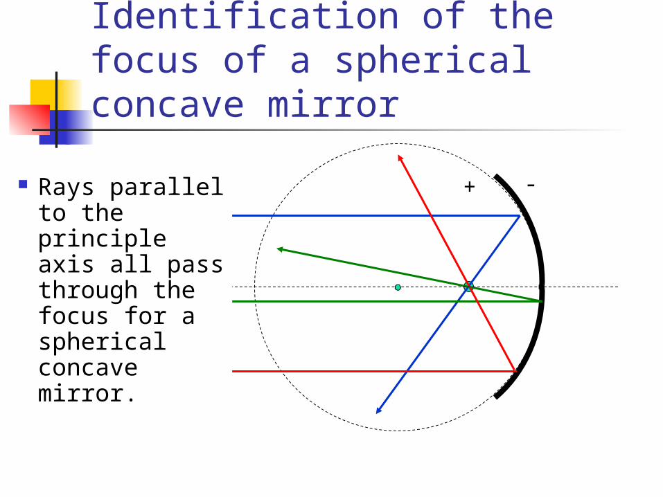
Identification of the focus of a spherical concave mirror
+ - Rays parallel to the principle axis all pass through the focus for a spherical concave mirror.
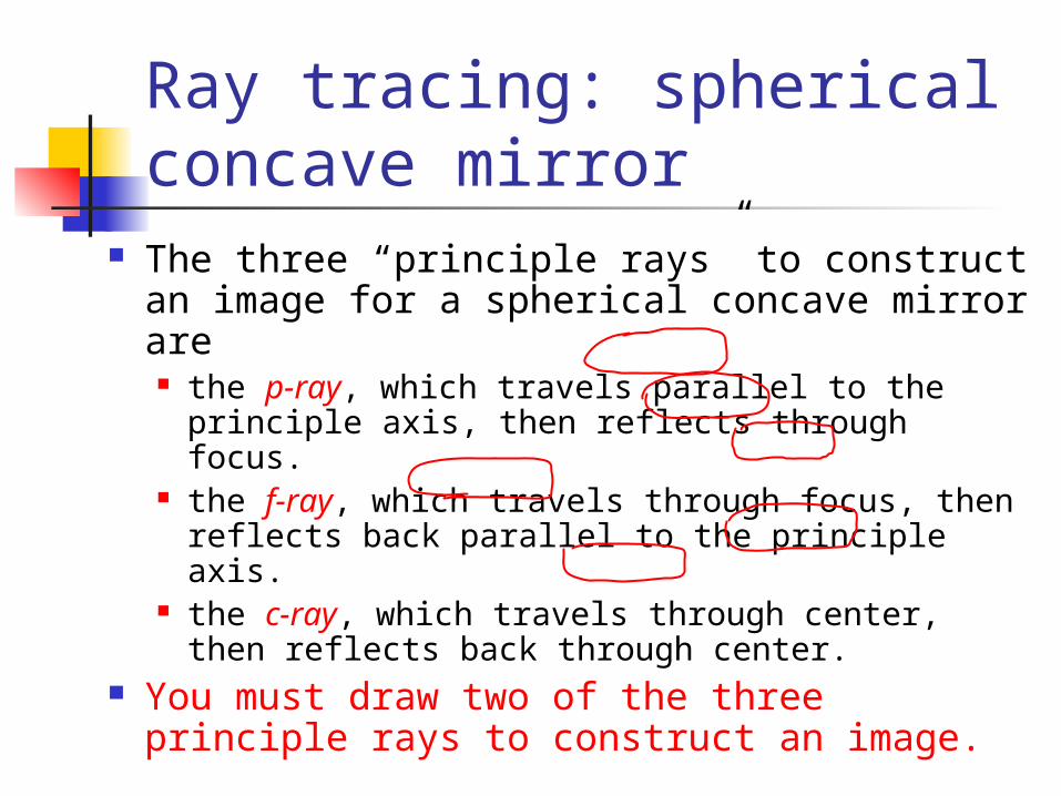
Ray tracing: spherical concave mirror
The three “principle rays” to construct an image for a spherical concave mirror are the p-ray, which travels parallel to the
principle axis, then reflects through focus. the f-ray, which travels through focus, then
reflects back parallel to the principle axis. the c-ray, which travels through center, then
reflects back through center. You must draw two of the three principle
rays to construct an image.

Ray tracing: spherical concave mirror
Construct the image for an object located outside the center of curvature.
It is only necessary to draw 2 of the three principle rays!
C F
Real, Inverted, Reduced
Image
p
f
c

C F
Real, Inverted,
True Image
Ray tracing: spherical concave mirror
Construct the image for an object located at the center of curvature.
Name the image.

C F
Real, Inverted, Enlarged
Image
Ray tracing: spherical concave mirror
Construct the image for an object located between the center of curvature and the focus.
Name the image.

C F
No image is formed.
Construct the image for an object located at the focus.
Ray tracing: spherical concave mirror

C F
Virtual, Upright,
Enlarged Image
Construct the image for an object located inside the focus.
Name the image.
Ray tracing: spherical concave mirror

Problema) Construct 2 ray diagrams to illustrate what
happens to the size of the image as an object is brought nearer to a spherical concave mirror when the object outside the focus.
b) Repeat part a) for an object which is brought nearer to the mirror but is inside the focus.

Solution a)
The image becomes larger when you move the object closer.

Solution b)
The image becomes smaller when you move the object closer.

Mirror equation #1 1/si + 1/so = 1/f
si: image distance so: object distance f: focal length

Mirror equation # 2 M = hi/ho = -si/so
si: image distance so: object distancem hi: image height ho: object height M: magnification

Sample Problem A spherical concave mirror, focal length 20 cm,
has a 5-cm high object placed 30 cm from it.a) Draw a ray diagram and construct the image.
c) Name the image

Sample Problem A spherical concave mirror, focal length 20 cm,
has a 5-cm high object placed 30 cm from it.b) Use the mirror equations to calculate
i. the position of image
ii. the magnification
iii. the size of image

Parts of aSpherical Convex Mirror
These are the main parts of a spherical convex mirror.
The focal length is half of the radius of curvature, and both are on the dark side of the mirror.
The focal length is negative for this type of mirror.
Principle axis
CenterFocus
+ -

Ray tracing: spherical convex mirror
Construct the image for an object located outside a spherical convex mirror.
Name the image.
F C
Virtual, Upright
, Reduce
d Image

Problem Construct 2 ray diagrams to illustrate what
happens to the size of the image as an object is brought nearer to a spherical convex mirror.

Problem A spherical concave mirror, focal length 10 cm,
has a 2-cm high object placed 5 cm from it.a) Draw a ray diagram and construct the image.
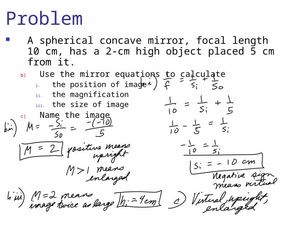
Problem A spherical concave mirror, focal length 10 cm,
has a 2-cm high object placed 5 cm from it.b) Use the mirror equations to calculate
i. the position of imageii. the magnificationiii. the size of image
c) Name the image

Problem A spherical convex mirror, focal length 15 cm,
has a 4-cm high object placed 10 cm from it.a) Draw a ray diagram and construct the image.
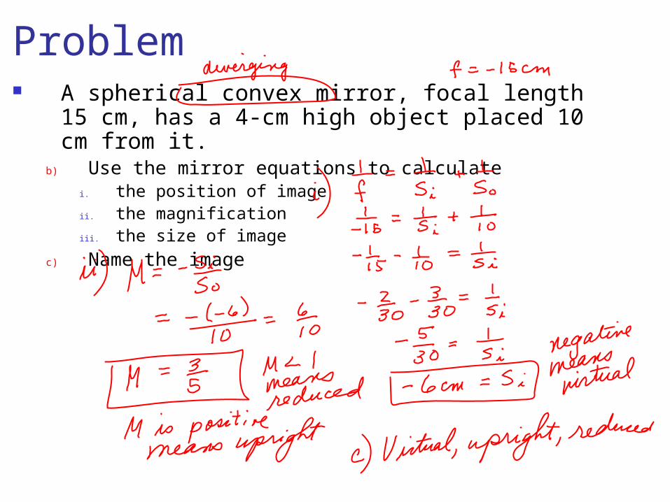
Problem A spherical convex mirror, focal length 15 cm,
has a 4-cm high object placed 10 cm from it.b) Use the mirror equations to calculate
i. the position of imageii. the magnificationiii. the size of image
c) Name the image
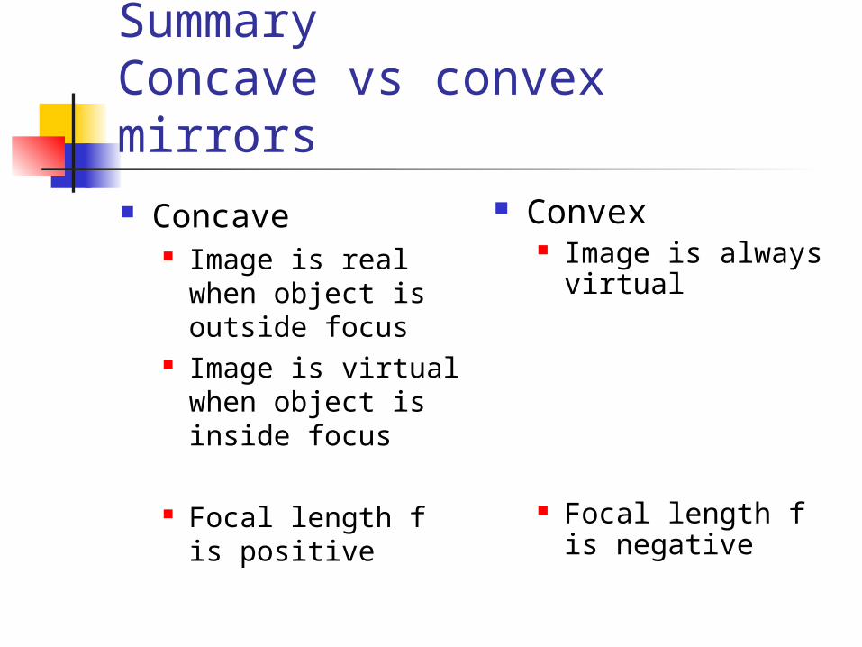
SummaryConcave vs convex mirrors Concave
Image is real when object is outside focus
Image is virtual when object is inside focus
Focal length f is positive
Convex Image is always
virtual
Focal length f is negative

Definition: Refraction Refraction is the movement of light
from one medium into another medium. Refraction cause a change in speed of
light as it moves from one medium to another.
Refraction can cause bending of the light at the interface between media.

Index of Refraction
speed of light in vacuumspeed of light in medium
n = c/v
n =

When light slows down… …it bends. Let’s take a look at a
simulation. URL:
http://www.walter-fendt.de/ph14e/huygenspr.htm

Snell’s Lawn1sin 1 = n2sin 2
n1
n2
1
angle of incidence
2
angle of refraction

n1 < n2
When the index of refraction increases, light bends toward the normal.
n1
n2
1
2When n1 < n2
1 > 2

n1 > n2
n1
n2
1
2
When the index of refraction decreases, light bends away from the normal.
When n1 > n2
1 < 2

Problem Light enters an oil from the air at an angle of 50o with
the normal, and the refracted beam makes an angle of 33o with the normal.
a) Draw this situation.b) Calculate the index of refraction of the oil.c) Calculate the speed of light in the oil

Problem Light enters water from a layer of oil at an angle of
50o with the normal. The oil has a refractive index of 1.65, and the water has a refractive index of 1.33.
a) Draw this situation.b) Calculate the angle of refraction.c) Calculate the speed of light in the oil, and in the water

ProblemLight enters a prism as shown, and passes through the prism.
a) Complete the path of the light through the prism, and show the angle it will make when it leaves the prism.
b) If the refractive index of the glass is 1.55, calculate the angle of refraction when it leaves the prism.
c) How would the answer to b) change if the prism were immersed in water?
30o
60oglass
air

Problem
Light enters a prism made of air from glass.a) Complete the path of the light through the prism, and show
the angle it will make when it leaves the prism.b) If the refractive index of the glass is 1.55, calculate the angle
of refraction when it leaves the prism.
30o
60o
glass
air

Dispersion The separation of white light into
colors due to different refractive indices for different wavelengths is called dispersion.
Dispersion is often called the prism effect.

Dispersion
Which color of light has the greatest refractive index?

Critical Angle of Incidence The smallest angle of incidence for
which light cannot leave a medium is called the critical angle of incidence.
If light passes into a medium with a greater refractive index than the original medium, it bends away from the normal and the angle of refraction is greater than the angle of incidence.
If the angle of refraction is > 90o, the light cannot leave the medium.

Critical Angle of Incidence
This drawing reminds us that when light refracts from a medium with a larger n into one with a smaller n, it bends away from the normal.
n1
n2
n1 > n2

Critical Angle of Incidence
This shows light hitting a boundary at the critical angle of incidence, where the angle of refraction is 90o. No refraction occurs!
n1
n2
c
r = 90o
n1 > n2
Ray reflects instead of refracting.

Critical Angle of Incidence
Instead of refraction, total internal reflection occurs when the angle of incidence exceeds the critical angle.
n1
n2
c
r = 90o
n1 > n2
Ray reflects instead of refracting.

Calculating Critical Angle
n1sin(1) = n2sin(90o) n1sin(c) = n2sin(90o) sin(c) = n2/ n1 c = sin-1(n2/n1)

Problem (separate sheet)A. What is the critical angle of incidence for a gemstone with
refractive index 2.45 if it is in air?
B. If you immerse the gemstone in water (refractive index 1.33), what does this do to the critical angle of incidence?

Lenses There are two types of lenses.
converging
++-
-(where refracted rays go)
Focal length, f, is positive
Focal length, f, is negative
(where refracted rays go)
diverging
Thicker in middle
Thinner in middle

Lens ray tracing Ray tracing is also used for lenses. We use the same principle rays we
used for mirrors. the p-ray, which travels parallel to the
principle axis, then refracts through focus. the f-ray, which travels through focus, then
refracts parallel to the principle axis. the c-ray, which travels through center and
continues without bending. You must draw 2 of the 3 principle rays.
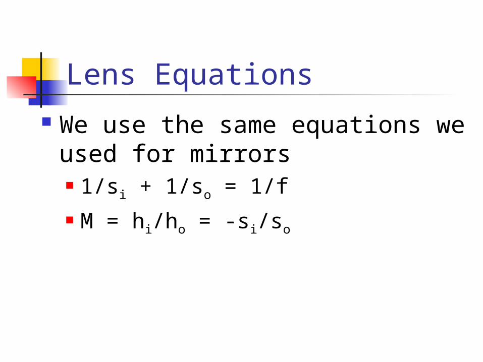
Lens Equations We use the same equations we
used for mirrors 1/si + 1/so = 1/f M = hi/ho = -si/so

Identification of the focus
All rays parallel to the principle axis refract through the focus of a converging lens.
F

Ray tracing: converging lens
Construct the image for an object located outside 2F.
It is only necessary to draw 2 of the three principle rays!
C F
Real, Inverted, Reduced
Image
F2F 2F
+-
p cf

Construct the image for an object located at 2F.
C F
Real, Inverted,
True Image
F2F 2F
+-
Ray tracing: converging lens

Construct the image for an object located between F and 2F.
C F
Real, Inverted, Enlarged
Image
F2F
+-
Ray tracing: converging lens
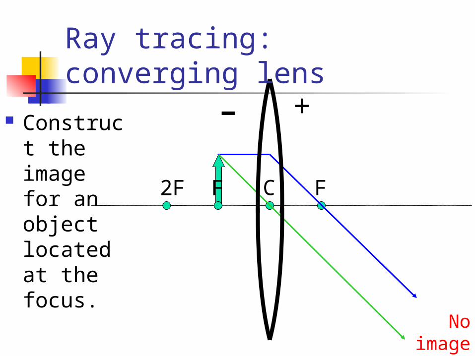
Construct the image for an object located at the focus.
C F
No image
F2F
+-
Ray tracing: converging lens

Construct the image for an object located inside the focus.
C F
Virtual, Upright,
Enlarged Image
F
+-
Ray tracing: converging lens

For converging lenses f is positive so is positive si is positive for real images and
negative for virtual images M is negative for real images and
positive for virtual images hi is negative for real images and
positive for virtual images

Diverging lens
Construct the image for an object located in front of a diverging lens.
C F
Virtual, Upright,
Reduced Image
F
+-
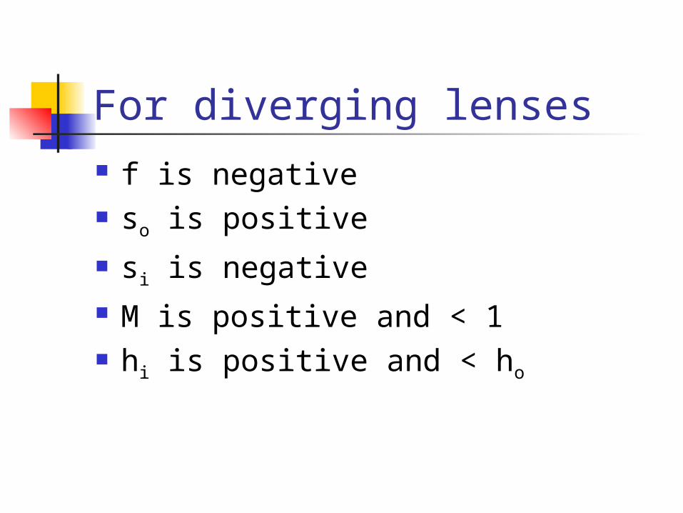
For diverging lenses f is negative so is positive si is negative M is positive and < 1 hi is positive and < ho

Problem A converging lens, focal length 20
cm, has a 5-cm high object placed 30 cm from it.
a) Draw a ray diagram and construct the image.
b) Use the lens equations to calculatei. the position of imageii. the magnificationiii. the size of image
c) Name the image

Solution a) and c)
C FF
+-a)
c) Real, Inverted, Enlarged

Solution b)
i. 1/si + 1/so = 1/f
1/si + 1/30 = 1/20
1/si = 1/20 - 1/30 = 3/60 –2/60 = 1/60
si = 60 cm
ii. M = - si/so = -60/30 = -2
iii. M = hi/ ho
hi = M ho= (-2)5 = -10 cm

Problem A converging lens, focal length 10
cm, has a 2-cm high object placed 5 cm from it.
a) Draw a ray diagram and construct the image.
b) Use the lens equations to calculatei. the position of imageii. the magnificationiii. the size of image
c) Name the image

Solution a) and c)
a)
c) Virtual, Upright, Enlarged
C FF
+-

Solution b)
i. 1/si + 1/so = 1/f
1/si + 1/5 = 1/10
1/si = 1/10 - 1/5 = 1/10 –2/10 = -1/10
si = -10 cm
ii. M = - si/so = -(-10)/5 = 2
iii. M = hi/ ho
hi = M ho= (2)2 = 4 cm

Problem A diverging lens, focal length -15
cm, has a 4-cm high object placed 10 cm from it.
a) Draw a ray diagram and construct the image.
b) Use the lens equations to calculatei. the position of imageii. the magnificationiii. the size of image
c) Name the image

Solution a) and c)
a)
c) Virtual, Upright, Reduced
C FF
+-

Solution b)
i. 1/si + 1/so = 1/f
1/si + 1/10 = 1/(-15)
1/si = -1/10 - 1/15 = -3/30 – 2/30 = -5/30 = -1/6
si = -6 cm
ii. M = - si/so = -(-6)/10 = 0.6
iii. M = hi/ ho
hi = M ho= (0.6)(4) = 2.4 cm