Geology and Soils Study for a Proposed 100MW Wind Energy ... site/appendices... · Wind Energy...
37
APPENDIX C Geology and Soils Study for a Proposed 100MW Wind Energy Project, Kajiado District, Kenya Report Prepared for Kipeto Energy Limited March 2012
Transcript of Geology and Soils Study for a Proposed 100MW Wind Energy ... site/appendices... · Wind Energy...

APPENDIX C
Geology and Soils Study for a Proposed 100MW Wind Energy Project, Kajiado District, Kenya
Report Prepared for
Kipeto Energy Limited
March 2012

Geology and Soils Study for a Proposed 100MW Wind Energy Project, Kajiado District,
Kenya
Prepared for:
Kipeto Energy Limited
14 Riverside, Riverside Drive, Westlands
P. O. Box 8366 – 00200
Nairobi, Kenya
Prepared by:
Eliud Wamwangi, Reg. Geologist P. O. Box 667 – 00517
NAIROBI
March 2012
Compiled by:
Mr. Eliud Wamwangi
Registered Geologist

TABLE OF CONTENTS
1 EXECUTIVE SUMMARY .............................................................. 5
2 INTRODUCTION ........................................................................ 7
2.1 Description of the Project Area .............................................................. 7
2.2 Objectives of the Study .......................................................................... 7
3 METHODOLOGY OF THE STUDY ................................................. 8
3.1 Desktop study ........................................................................................ 8
3.2 Field Survey Methodology ..................................................................... 8
3.2.1 Reconnaissance survey .................................................................................... 8
3.2.2 Geophysical survey .......................................................................................... 8
3.2.3 Digging of Trial pits .......................................................................................... 9
4 BASELINE STUDY OF THE SOILS AND GEOLOGY CONDITIONS ... 10
4.1 Soils ..................................................................................................... 10
4.1.1 Introduction ................................................................................................... 10
4.1.2 Type of Soils ................................................................................................... 10
4.1.3 Results of Digging Trial pits ............................................................................ 10
4.2 Geology ............................................................................................... 12
4.2.1 Introduction ................................................................................................... 12
4.2.2 Geology of Project Area ................................................................................. 12
4.2.3 Results of Geophysics..................................................................................... 15
5 POTENTIAL IMPACTS ON THE SOILS AND GEOLOGY ................. 17
5.1 Introduction ......................................................................................... 17
5.2 Potential Impacts in Construction phase ............................................. 17
5.3 Potential Impacts in Operational Phase ............................................... 19
6 IMPACT ASSESSMENT ............................................................. 20
7 PROPOSED MITIGATION MEASURES ........................................ 23
7.1 Mitigation Measures in Construction Phase ........................................ 23
7.2 Mitigation Measures in Operational Phase .......................................... 24
8 ENVIRONMENTAL MANAGEMENT PLAN .................................. 25
9 CONCLUSIONS ARISING FROM THE STUDY .............................. 26
9.1 Conclusions.......................................................................................... 26
9.2 Recommended Future Monitoring Requirements ............................... 26
10 GAPS IN KNOWLEDGE AND UNCERTAINTIES ......................... 27
10.1 Gaps in Knowledge ........................................................................... 27
10.2 Uncertainties Encountered During Study .......................................... 27
11 APPENDICES ......................................................................... 28
12 PICTURES OF SOME CAVES ENCOUNTERED IN THE PROJECT AREA ........................................................................................... 35

KipetoGeologyandSoilsStudy Page5
1 EXECUTIVESUMMARY
This Report presents the results of a baseline study of the Soils and Geology of Kipeto area where a wind farm project is proposed. It is located in Kipeto/Oloyiankalani Sub-location, Keekonyokie Location of Ngong Division in Kajiado North District. The Kipeto area is generally a highland volcanic plain and plateau standing above the lower Athi plains to the east and the Rift Valley System to the west. The relatively high altitude of the area makes it ideal for a wind farm project due to the good windy conditions that prevail there. The project targets to produce about 100 megawatts of electricity power at the project’s maturity development.
Kipeto area is predominantly covered by black cotton soil which is underlain by volcanic rocks, mainly agglomerates, tuffs and phonolites. The area has several faults running north-south. There are also small to medium sized caves found in some of the outcrops of the volcanic rocks spread out in the area. This report outlines the baseline soil and geological environment, the sensitivity of this baseline environment in relation to the proposed project and the potential impacts that may emanate due to it. Mitigation measures are recommended in order to ensure that the potential adverse impacts of the proposed project on this environment are mitigated.
The report concludes that the greatest disturbance and risk to pollution of the soils and geology is expected during the construction phase of the project as this is when there will be a lot of excavation for the wind turbine foundations, access tracks construction, trenching for underground cables, and construction of a substation. It will also be the time when there will be a lot of vehicles and heavy machinery at the site that may be sources of hydro-carbon substance leaks.
Mitigation measures recommended include construction of access tracks with stone and laterite (murram) that are well compacted to carry the weight of expected heavy vehicles. The tracks should also be constructed in such a way as to allow for easy drainage of surface run-off on either side of the track to minimize the potential for water-logging and land slippage around the track. In steeply sloped areas the side drainage trenches of the tracks should have concrete barriers at intervals of around 30 to 50 metres (depending on the slope) to check erosion and deep cutting of the trench. Stockpiles of excavated materials will be stored in designated areas at minimum distance of 10m from any nearby watercourses or drains to minimize risk of silt laden surface water runoff entering water courses.
Other mitigation measures include refueling of vehicles/machinery offsite. Where necessary, construction machinery will be re-fuelled onsite by means of a mobile fuel bowser by experienced personnel. This will be done only at designated, bunded area of hard-standing that is situated a minimum of 10m from surface water bodies. The volume of traffic is expected to significantly decrease after the construction phase and at full operation of the wind turbines. This will consequently decrease risk of spillage and leakage of oils, fuels and other contaminants as the only vehicles expected will be those bringing the maintenance crew.

KipetoGeologyandSoilsStudy Page6
It is however, recommended that routine checks are carried out around the wind turbine sites to ensure that any leakage of oil/petroleum from the maintenance vehicles does not go undetected. A spill kit will be located within the depot to ensure that any minor leaks of oil are cleaned up immediately on detection.
KipetoGeologyandSoilsStudy Page7
2 INTRODUCTION
2.1 DescriptionoftheProjectArea
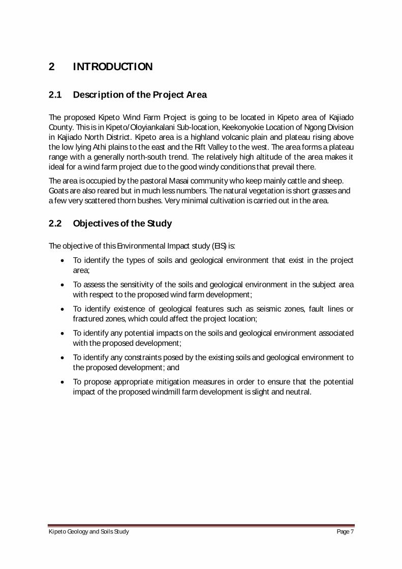
The proposed Kipeto Wind Farm Project is going to be located in Kipeto area of Kajiado County. This is in Kipeto/Oloyiankalani Sub-location, Keekonyokie Location of Ngong Division in Kajiado North District. Kipeto area is a highland volcanic plain and plateau rising above the low lying Athi plains to the east and the Rift Valley to the west. The area forms a plateau range with a generally north-south trend. The relatively high altitude of the area makes it ideal for a wind farm project due to the good windy conditions that prevail there.
The area is occupied by the pastoral Masai community who keep mainly cattle and sheep. Goats are also reared but in much less numbers. The natural vegetation is short grasses and a few very scattered thorn bushes. Very minimal cultivation is carried out in the area.
2.2 ObjectivesoftheStudy
The objective of this Environmental Impact study (EIS) is:
· To identify the types of soils and geological environment that exist in the project area;
· To assess the sensitivity of the soils and geological environment in the subject area with respect to the proposed wind farm development;
· To identify existence of geological features such as seismic zones, fault lines or fractured zones, which could affect the project location;
· To identify any potential impacts on the soils and geological environment associated with the proposed development;
· To identify any constraints posed by the existing soils and geological environment to the proposed development; and
· To propose appropriate mitigation measures in order to ensure that the potential impact of the proposed windmill farm development is slight and neutral.
KipetoGeologyandSoilsStudy Page8
3 METHODOLOGYOFTHESTUDY
3.1 Desktopstudy
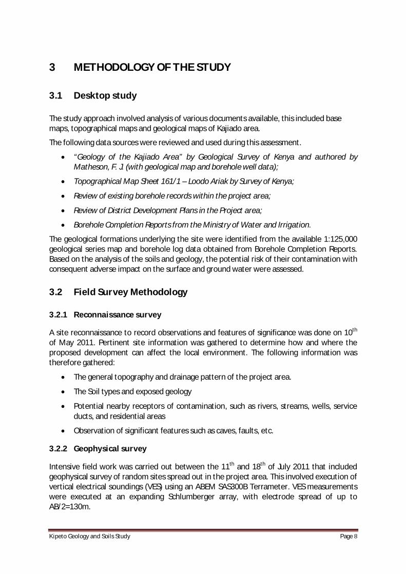
The study approach involved analysis of various documents available, this included base maps, topographical maps and geological maps of Kajiado area.
The following data sources were reviewed and used during this assessment.
· “Geology of the Kajiado Area” by Geological Survey of Kenya and authored by Matheson, F. J. (with geological map and borehole well data);
· Topographical Map Sheet 161/1 – Loodo Ariak by Survey of Kenya;
· Review of existing borehole records within the project area;
· Review of District Development Plans in the Project area;
· Borehole Completion Reports from the Ministry of Water and Irrigation.
The geological formations underlying the site were identified from the available 1:125,000 geological series map and borehole log data obtained from Borehole Completion Reports. Based on the analysis of the soils and geology, the potential risk of their contamination with consequent adverse impact on the surface and ground water were assessed.
3.2 FieldSurveyMethodology
3.2.1 Reconnaissancesurvey
A site reconnaissance to record observations and features of significance was done on 10th of May 2011. Pertinent site information was gathered to determine how and where the proposed development can affect the local environment. The following information was therefore gathered:
· The general topography and drainage pattern of the project area.
· The Soil types and exposed geology
· Potential nearby receptors of contamination, such as rivers, streams, wells, service ducts, and residential areas
· Observation of significant features such as caves, faults, etc.
3.2.2 Geophysicalsurvey
Intensive field work was carried out between the 11th and 18th of July 2011 that included geophysical survey of random sites spread out in the project area. This involved execution of vertical electrical soundings (VES) using an ABEM SAS300B Terrameter. VES measurements were executed at an expanding Schlumberger array, with electrode spread of up to AB/2=130m.

KipetoGeologyandSoilsStudy Page9
The basic principles of resistivity method, is that the electrical properties of rocks in the upper part of the earth’s crust are determined by lithology, porosity and the degree of pore space saturation and the salinity of the pore water. These factors contribute to the resistivity of a material (the reciprocal of the electrical conductivity). The nature of the subsurface geological formation and the depth to the base rock and aquifers can thus be determined.
3.2.3 DiggingofTrialpits
The excavation of trial pits in the project area was carried out simultaneously with the geophysical survey between the 11th and 18th of July 2011 to find out the nature and type of the top-soil and determine the depth to base rock. The trial pit sites were at the point of the VES sites. The trial pit sites concentrated on the crests and flat raised ground in the Kipeto area as they were considered to be likely target areas for location of the windmill masts. There was also a bias on farms where the owners had agreed on their use for the project and had signed agreements on the same.
KipetoGeologyandSoilsStudy Page10
4 BASELINESTUDYOFTHESOILSANDGEOLOGYCONDITIONS
4.1 Soils
4.1.1 Introduction
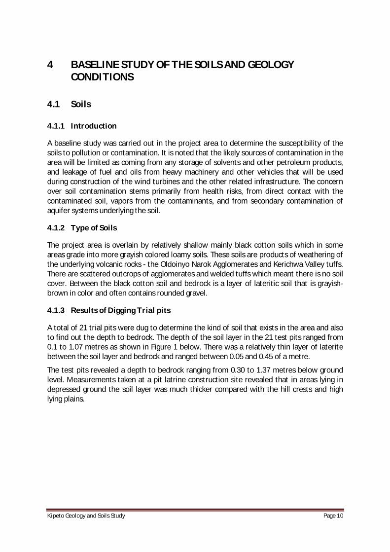
A baseline study was carried out in the project area to determine the susceptibility of the soils to pollution or contamination. It is noted that the likely sources of contamination in the area will be limited as coming from any storage of solvents and other petroleum products, and leakage of fuel and oils from heavy machinery and other vehicles that will be used during construction of the wind turbines and the other related infrastructure. The concern over soil contamination stems primarily from health risks, from direct contact with the contaminated soil, vapors from the contaminants, and from secondary contamination of aquifer systems underlying the soil.
4.1.2 TypeofSoils
The project area is overlain by relatively shallow mainly black cotton soils which in some areas grade into more grayish colored loamy soils. These soils are products of weathering of the underlying volcanic rocks - the Oldoinyo Narok Agglomerates and Kerichwa Valley tuffs. There are scattered outcrops of agglomerates and welded tuffs which meant there is no soil cover. Between the black cotton soil and bedrock is a layer of lateritic soil that is grayish-brown in color and often contains rounded gravel.
4.1.3 ResultsofDiggingTrialpits
A total of 21 trial pits were dug to determine the kind of soil that exists in the area and also to find out the depth to bedrock. The depth of the soil layer in the 21 test pits ranged from 0.1 to 1.07 metres as shown in Figure 1 below. There was a relatively thin layer of laterite between the soil layer and bedrock and ranged between 0.05 and 0.45 of a metre.
The test pits revealed a depth to bedrock ranging from 0.30 to 1.37 metres below ground level. Measurements taken at a pit latrine construction site revealed that in areas lying in depressed ground the soil layer was much thicker compared with the hill crests and high lying plains.

KipetoGeologyandSoilsStudy Page11
Source: Wamwangi, E. K. (2011)
The soil layer in the pit latrine was 1.42 metres while the lateritic layer was 0.91 of a metre. The data of each trial pit is summarized in Table 1 below:
Table 1: Summary of Trial Pit Data
VES No. of Pit Site
UTM Location 37m Altitude (m.a.s.l.)
Thickness (m) Depth to Bedrock (m) Easting Southing Top soil Laterite
4 0242441 9808866 2002 1.02 0.07 1.09
5 0239017 9808084 1907 0.25 0.05 0.30
6 0239740 9808772 1934 0.71 0.05 0.76
7 0240796 9809114 2000 0.81 0.10 0.91
8 0243595 9809550 2037 0.46 0.05 0.51
9 0244515 9811712 1966 0.53 0.13 0.66
10 0243557 9812014 1997 0.38 0.13 0.51
11 0242105 9812346 2026 0.51 0.10 0.61
12 0240190 9810628 1986 0.46 0.07 0.53
13 0240978 9817064 1914 0.46 0.15 0.61
14 0240316 9816312 1987 1.07 0.30 1.37
15 0240344 9815440 2015 0.56 0.08 0.64
16 0243013 9814302 2028 0.46 0.07 0.53
17 0244263 9814964 1986 0.51 0.05 0.56
18 0237580 9808744 1980 0.48 0.18 0.66
0.1 – 1.07m
0.05 – 0.45m
Figure 1: Sketch of a Test Pit
Black cotton soil
Laterite and gravel
Volcanic rock (tuff or phonolite)
Ground level

KipetoGeologyandSoilsStudy Page12
VES No. of Pit Site
UTM Location 37m Altitude (m.a.s.l.)
Thickness (m) Depth to Bedrock (m) Easting Southing Top soil Laterite
19 0237894 9809564 1989 0.41 0.20 0.61
20 0238433 9810556 2022 0.28 0.31 0.59
21 0242623 9812022 2016 0.2 0.45 0.65
22 0244653 9808990 1921 0.1 0.28 0.38
23 0243706 9809438 2028 0.41 0.07 0.48
24 0243036 9808120 2008 0.41 0.18 0.59
The relatively shallow soil profile implies that any contaminant percolating in the soil will reach the bedrock rather quickly and start spreading directed by the bedrock profile. Contamination of the deeper subsurface geological formations and aquifers may also take place through fractures within the bedrock which would allow vertical penetration of contaminants
4.2 Geology
4.2.1 Introduction
The general geology of the project area comprises of Tertiary volcanic rocks which overlay the Archaean Basement System forming an unconformity. The volcanic rocks are associated with the formation of the Rift Valley system on the western side of the project area. The extrusion of the various layers of volcanic rocks took place in the Pliocene to Miocene period which is associated with the most active period of the rift faulting. The Basement System is part of the metamorphic Mozambique Belt that stretches from Mozambique in the south through Tanzania, Kenya and into Ethiopia to the north.
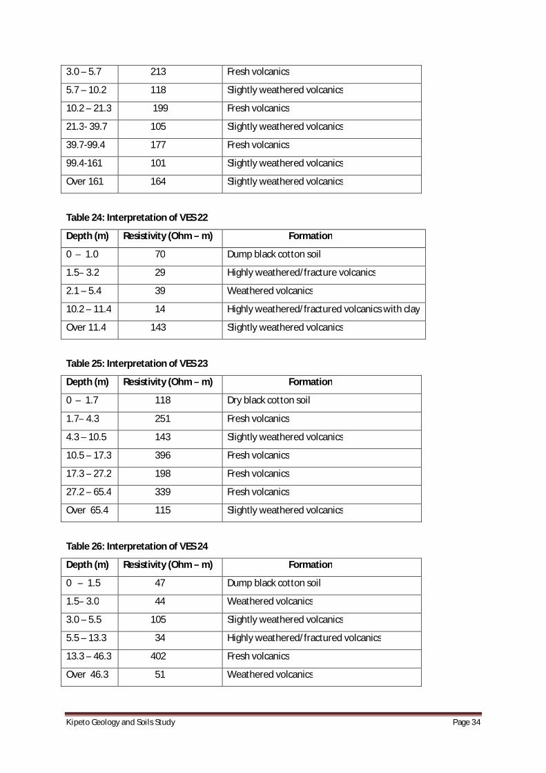
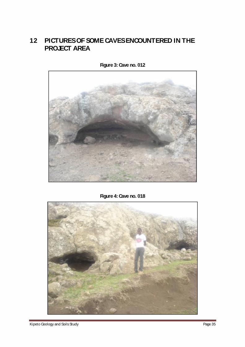
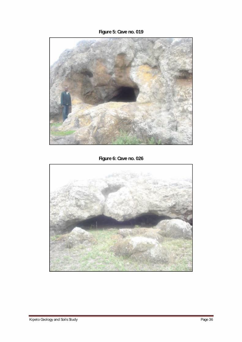
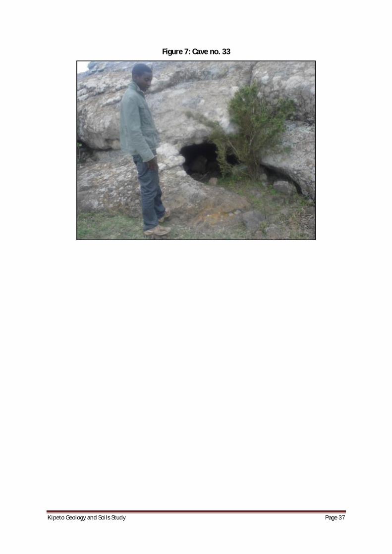
The project area lies in the Ol Doinyo Narok plateau which ranges between 1850 and 2035 metres above mean sea level. The area has many faults with a predominant north-south trend. There are prominent outcrops of phonolites and trachytic tuffs spread in the area. Small to medium sized caves were also observed with the small ones averaging around three metres wide by one metre high and two metres horizontal depth. The largest cave was about 25m wide, 7.5m high and 10m deep (see Figures 3 to 7 in the Appendices). Not much is known about the genesis of these caves but some had indications of being partly due to erosion by water.
4.2.2 GeologyofProjectArea
The geology of Kipeto area is composed of a generally thin layer of black cotton soil which is underlain by agglomerates of tuffs, trachytes and phonolites. Most of the area is covered by Ol Doinyo Narok Agglomerates which grades into Kerichwa Valley tuffs in the north of the project area. Figure 2 illustrates the surface geology. Below is the geologic succession of the area:
KipetoGeologyandSoilsStudy Page13
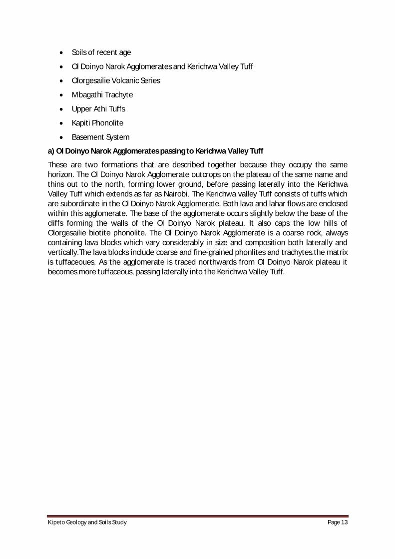
· Soils of recent age
· Ol Doinyo Narok Agglomerates and Kerichwa Valley Tuff
· Olorgesailie Volcanic Series
· Mbagathi Trachyte
· Upper Athi Tuffs
· Kapiti Phonolite
· Basement System
a) Ol Doinyo Narok Agglomerates passing to Kerichwa Valley Tuff
These are two formations that are described together because they occupy the same horizon. The Ol Doinyo Narok Agglomerate outcrops on the plateau of the same name and thins out to the north, forming lower ground, before passing laterally into the Kerichwa Valley Tuff which extends as far as Nairobi. The Kerichwa valley Tuff consists of tuffs which are subordinate in the Ol Doinyo Narok Agglomerate. Both lava and lahar flows are enclosed within this agglomerate. The base of the agglomerate occurs slightly below the base of the cliffs forming the walls of the Ol Doinyo Narok plateau. It also caps the low hills of Olorgesailie biotite phonolite. The Ol Doinyo Narok Agglomerate is a coarse rock, always containing lava blocks which vary considerably in size and composition both laterally and vertically.The lava blocks include coarse and fine-grained phonlites and trachytes.the matrix is tuffaceoues. As the agglomerate is traced northwards from Ol Doinyo Narok plateau it becomes more tuffaceous, passing laterally into the Kerichwa Valley Tuff.
Project Site
KipetoGeologyandSoilsStudy Page14
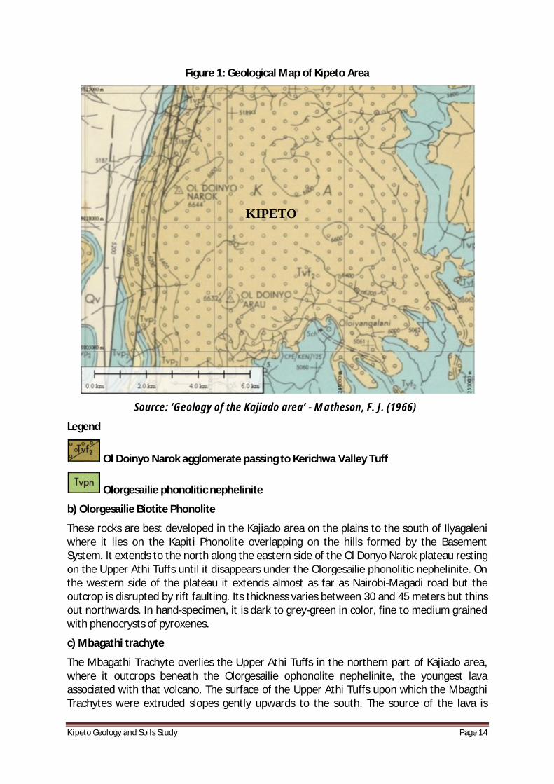
Figure 1: Geological Map of Kipeto Area
Source: ‘Geology of the Kajiado area’ - Matheson, F. J. (1966)
Legend
Ol Doinyo Narok agglomerate passing to Kerichwa Valley Tuff
Olorgesailie phonolitic nephelinite
b) Olorgesailie Biotite Phonolite
These rocks are best developed in the Kajiado area on the plains to the south of Ilyagaleni where it lies on the Kapiti Phonolite overlapping on the hills formed by the Basement System. It extends to the north along the eastern side of the Ol Donyo Narok plateau resting on the Upper Athi Tuffs until it disappears under the Olorgesailie phonolitic nephelinite. On the western side of the plateau it extends almost as far as Nairobi-Magadi road but the outcrop is disrupted by rift faulting. Its thickness varies between 30 and 45 meters but thins out northwards. In hand-specimen, it is dark to grey-green in color, fine to medium grained with phenocrysts of pyroxenes.
c) Mbagathi trachyte
The Mbagathi Trachyte overlies the Upper Athi Tuffs in the northern part of Kajiado area, where it outcrops beneath the Olorgesailie ophonolite nephelinite, the youngest lava associated with that volcano. The surface of the Upper Athi Tuffs upon which the Mbagthi Trachytes were extruded slopes gently upwards to the south. The source of the lava is
KIPETO
KipetoGeologyandSoilsStudy Page15
thought to be to the north where it is thickest while it peters out southwards. When fresh the trachyte is grey in color and has numerous small laths of clear feldspar, usually orientating in the direction of flow which are set in a thick trachytic mix. Weathered surfaces are soft and rusty-brown in color.
d) Upper Athi Tuffs
These are a group of tuffs and ashes laid down by explosive volcanic activity on top of the western part of the Kapiti Phonlite. It is thought they were laid down in water because they are stratified. As the tuffs are friable they do not build any pronounced features but form a capping on the Kapiti Phonolite that is exposed for long distances along rivers that have rapidly eroded through the Upper Athi Tuffs. They are light grey when fresh and yellowish when weathered. Bands which are darker and lighter in colour are subordinate, but crystals of feldspars and melanocratic minerals are often scattered in the matrix.
e) Kapiti Phonolites
The Kapiti phonolite forms a flat surface with little dissections and has few outcrops except in some river valleys. On the plains it occurs as rounded exfoliated boulders. Its thickness is variable since it was extruded around hills rising above the sub-Miocene peneplain, but attains a maximum of between 60 and 90 metres at the edge of the Rift Valley.
The rocks consist of a dark greenish grey microcrystalline groundmass with numerous large, white, elongated feldspar phenocrysts and less frequent waxy, nepheline hexagons. The Kapiti Phonolite is thought to have been extruded from fissures or small vents because no associated central volcanoes are visible where it occurs, although they could be buried under younger rocks.
f) Basement System
The Basement system forms the floor of the volcanics and represents an old land surface with considerable relief. The gneisses, limestones and quartzites of the Basement system are thought to be sedimentary in origin because of their composition and layering. These rocks are not exposed in the project area but can be found further east in the lower plains towards Kajiado Town.
4.2.3 ResultsofGeophysics
The interpreted geophysical data indicates that the general area in which the wind farm project is going to be constructed has the following characteristics:
· The subsurface geological formations are highly fractured and most of the layers have true resistivity of less than 100 Ohm-metre.
· There are shallow aquifers of between 20 and 40 metres below ground level and deeper aquifers of between 100 and 150 metres below ground level.
· The upper sub-surface geology is vulnerable to the infiltration of hydro-carbon pollutants in the event of leakage of petroleum hydrocarbons from heavy vehicles operating in the project area during construction which could lead to the local aquifer systems being contaminated.
· The rock strength is comprised with fractures, weathering.
KipetoGeologyandSoilsStudy Page16
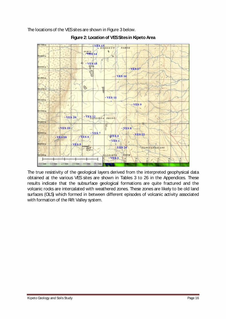
The locations of the VES sites are shown in Figure 3 below.
Figure 2: Location of VES Sites in Kipeto Area
The true resistivity of the geological layers derived from the interpreted geophysical data obtained at the various VES sites are shown in Tables 3 to 26 in the Appendices. These results indicate that the subsurface geological formations are quite fractured and the volcanic rocks are intercalated with weathered zones. These zones are likely to be old land surfaces (OLS) which formed in between different episodes of volcanic activity associated with formation of the Rift Valley system.

KipetoGeologyandSoilsStudy Page17
5 POTENTIALIMPACTSONTHESOILSANDGEOLOGY
5.1 Introduction
The potential impacts on the soils and geological environment as a result of implementation of the proposed windmill farm project, in the absence of suitable mitigation measures, are expected to be as follows:
· Disturbance of soils and subsurface geological formations during the following activities:
o Creation of temporary construction compounds and crane platform areas;
o Construction of foundations for the wind turbines;
o Construction of a substation;
o Upgrade of existing access tracks and construction of new access tracks.
o Laying of electrical cables.
· Disposal of excess excavated material that could potentially be eroded to water bodies;
· Leakage of oil and fuels from storage areas and from site vehicles and machinery.
5.2 PotentialImpactsinConstructionphase
The construction phase of the proposed wind farm project involves the following key activities that may have potential adverse impacts on the local soils and geology, if not appropriately managed:
· Excavation and stockpiling of material at the location of proposed wind turbine masts and access tracks;
· Disposal of excess excavated material;
· Pollution of nearby surface water from the wash out from the excavated materials;
· Contamination of soils, surface water and groundwater from leakage of oils and fuel;
· Excavation of laterite material (murram) for grading of access tracks.
Effects that can occur during construction or operations include:
o Cut and fill activities leading to soil erosion
o Removal of vegetation and landscaping leading to soil erosion
o Use of heavy equipment resulting in soil compaction
o Impacts to fractured topography (surface collapse)
o Impervious surface increase resulting in increased runoff and soil erosion

KipetoGeologyandSoilsStudy Page18
o Vehicle movements on unpaved surfaces resulting in increased soil erosion and compaction
o Fires resulting in reduced vegetation and increased soil erosion
o Increased vulnerability to a geologic hazard such as seismic activity and the probability that such an event could result in injury.
There is the potential for the loss of soil and other excavated material through erosion caused by run off during rainy weather or from wind during the dry period during the construction phase of the proposed development. This is considered a negative and moderate impact in the absence of suitable mitigation measures. The nature of the construction activities will involve the stripping and stockpiling of soil and other excavated material until it is reinstated, when required.
The continuous use of heavy machinery and other vehicles on unsealed areas of ground has the potential to adversely impact on the soil structure, which is considered a direct impact. This is considered a negative and moderate impact in the absence of suitable mitigation measures. The wind turbines and associated structures will be located in range land areas and therefore the use of machinery will be limited to assigned access tracks and areas agreed with landowners. The time taken for the use of heavy machinery on each part of the site will be limited. During construction of the wind turbines, there is a risk of accidental pollution incidences, which are considered direct impacts, from the following sources:
· Spillage or leakage of oils and fuels stored on site;
· Spillage or leakage of oils and fuels from construction machinery or site vehicles;
· Spillage of oil or fuel from refueling machinery on site;
· Spillage or leakage from onsite toilet facilities; and
· The use of concrete and cement for the foundations of the wind turbines.
Laterite material (murram) to be used for grading the access tracks will be obtained from outside the project area. Thick layers of laterite are available in the area of Basement System rock formations found to the east of Kipeto towards Kajiado Town. To excavate this resource the proponent needs to make an agreement with the land owner, get a letter of no objection from the Mines and Geology Department in the Ministry of Environment and Mineral Resources, and get another letter of no objection from the National Environmental Management Authority (NEMA).
The above potential impacts are considered negative and significant. During the initial site preparation and construction stage, there will be a large volume of machinery on the subject site, which is likely to include diesel powered trucks, excavators, bulldozers, cranes and graders.
The potential impacts to the underlying soil from the construction of the proposed development could derive from accidental spillage of fuels, oils, paints and solvents, which could adversely affect soil and bedrock quality, if allowed to infiltrate to ground during storage and dispensing operations. The underlying groundwater quality could also be affected, indirectly, if surface contamination migrates downwards.

KipetoGeologyandSoilsStudy Page19
5.3 PotentialImpactsinOperationalPhase
The operation of the proposed wind farm project is not expected to have a notable impact on the underlying soil or geological environment during normal operating conditions. Routinely vehicles carrying maintenance staff will visit the site. Potential impacts on the soils and geological environment during the operational phase are expected to include minor, localized contamination in the event of leakage of oil/fuel from the maintenance vehicles. This is considered a direct, negative, short term and very slight impact. The construction of access tracks using a stone base and the presence of a surface water drain alongside the access track will help prevent rutting and gulling of the ground surface.
KipetoGeologyandSoilsStudy Page20
6 IMPACTASSESSMENT
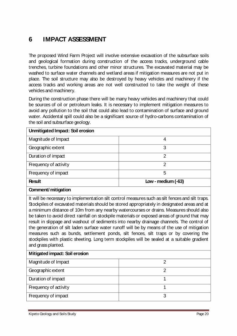
The proposed Wind Farm Project will involve extensive excavation of the subsurface soils and geological formation during construction of the access tracks, underground cable trenches, turbine foundations and other minor structures. The excavated material may be washed to surface water channels and wetland areas if mitigation measures are not put in place. The soil structure may also be destroyed by heavy vehicles and machinery if the access tracks and working areas are not well constructed to take the weight of these vehicles and machinery.
During the construction phase there will be many heavy vehicles and machinery that could be sources of oil or petroleum leaks. It is necessary to implement mitigation measures to avoid any pollution to the soil that could also lead to contamination of surface and ground water. Accidental spill could also be a significant source of hydro-carbons contamination of the soil and subsurface geology.
Unmitigated Impact: Soil erosion
Magnitude of Impact 4
Geographic extent 3
Duration of impact 2
Frequency of activity 2
Frequency of impact 5
Result Low - medium (-63)
Comment/mitigation
It will be necessary to implementation silt control measures such as silt fences and silt traps. Stockpiles of excavated materials should be stored appropriately in designated areas and at a minimum distance of 10m from any nearby watercourses or drains. Measures should also be taken to avoid direct rainfall on stockpile materials or exposed areas of ground that may result in slippage and washout of sediments into nearby drainage channels. The control of the generation of silt laden surface water runoff will be by means of the use of mitigation measures such as bunds, settlement ponds, silt fences, silt traps or by covering the stockpiles with plastic sheeting. Long term stockpiles will be sealed at a suitable gradient and grass planted.
Mitigated impact: Soil erosion
Magnitude of Impact 2
Geographic extent 2
Duration of impact 1
Frequency of activity 1
Frequency of impact 3

KipetoGeologyandSoilsStudy Page21
Result Very low (-20)
Unmitigated Impact: Ground contamination from oil, fuel and chemical leaks
Magnitude of Impact 4
Geographic extent 3
Duration of impact 4
Frequency of activity 3
Frequency of impact 4
Result Medium – High (-77)
Comment/mitigation
Storage of chemicals will be in bunded areas of sufficient capacity while refueling of vehicles/machinery will be expected to be done offsite. Where necessary, construction machinery will be re-fuelled onsite by means of a mobile fuel bowser done by trained personnel. This will be done in designated, bunded areas of hard-standing that are situated a minimum of 10m from surface water bodies. A spill tray and an emergency response spill kit will be brought onto the site with the mobile fuel bowser during refueling operations.
Mitigated impact: Ground contamination from oil, fuel and chemical leaks
Magnitude of Impact 2
Geographic extent 2
Duration of impact 2
Frequency of activity 2
Frequency of impact 2
Result Very low (-24)
Unmitigated Impact: Destruction of soil structure by heavy vehicles
Magnitude of Impact 3
Geographic extent 2
Duration of impact 4
Frequency of activity 4
Frequency of impact 4
Result Low – Medium (-72)
Comment/mitigation
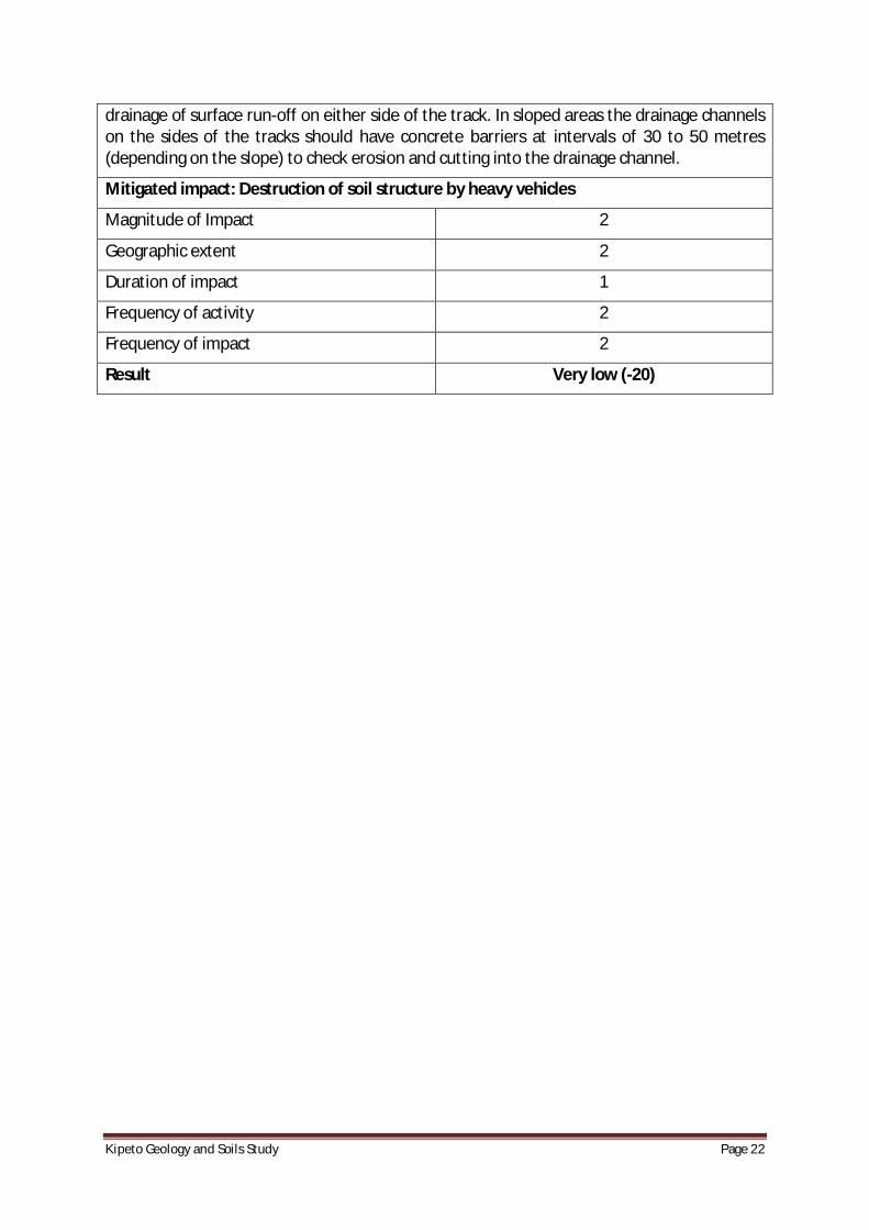
Used of approved access routes and use of stone and laterite (murram) on access tracks to protect underlying soil. This should be well compacted in order to carry the weight of the expected heavy vehicles. The tracks should be constructed in such a way as to allow for easy
KipetoGeologyandSoilsStudy Page22
drainage of surface run-off on either side of the track. In sloped areas the drainage channels on the sides of the tracks should have concrete barriers at intervals of 30 to 50 metres (depending on the slope) to check erosion and cutting into the drainage channel.
Mitigated impact: Destruction of soil structure by heavy vehicles
Magnitude of Impact 2
Geographic extent 2
Duration of impact 1
Frequency of activity 2
Frequency of impact 2
Result Very low (-20)

KipetoGeologyandSoilsStudy Page23
7 PROPOSEDMITIGATIONMEASURES
7.1 MitigationMeasuresinConstructionPhase
It is proposed that the access tracks be constructed of stone and laterite (murram) which should be well compacted in order to carry the weight of the expected heavy vehicles. This should consequently minimize the potential for soil erosion through surface runoff and also minimize the destruction of the soil structure, which could occur by the continuous use of these heavy vehicles on unsealed tracks. The tracks should be constructed in such a way as to allow for easy drainage of surface run-off on either side of the track. This will minimize the potential for water-logging and land slippage around the track. In sloped areas the drainage channels on the sides of the tracks should have concrete barriers at intervals of 30 to 50 metres (depending on the slope) to check erosion and deepening of the drainage channel.
Stockpiles of excavated materials should be stored appropriately in a designated area of the site at a minimum distance of 10m from any nearby watercourses or drains. Measures should also be taken to avoid rainfall on stockpile materials or exposed areas of ground resulting in slippage and washout of sediments into nearby drainage channels. As most of the excavated material is expected to be reused, the generation of significant quantities of surplus spoil is not expected. Excess excavation material should be removed from the site and appropriately deposited in a designated area where it will have minimal chances of being eroded into drainage channels. This would best be in a depressed area that does not have an outlet into the local drainage system.
The control of the generation of silt laden surface water runoff will be by means of the use of mitigation measures such as bunds, settlement ponds, silt fences or by covering the stockpiles with plastic sheeting. Any runoff from stockpiles will be passed through a silt trap or buffer zone prior to any discharge to local watercourses. Stockpiles will be sealed at a suitable gradient and grass planted, if stored long term.
The refueling of vehicles/machinery will be expected to be done offsite. Where necessary, construction machinery will be re-fuelled onsite by means of a mobile fuel bowser (comprising a double skinned tank) accompanied by trained personnel. Refueling operations will only take place at a designated, bunded area of hard-standing that is situated a minimum of 10m from surface water bodies. A spill tray and an emergency response spill kit will be brought onto the site with the mobile fuel bowser during refueling operations. Site personnel operating machinery or vehicles on the site will be trained in the use of emergency spill kits. The spill tray will be placed beneath the fill point of the vehicle and the emergency response spill kit will be used in the event of an accidental spill.
In order to minimize any adverse impact on the underlying subsurface strata from material spillages, all oils, solvents and paints used during construction will be stored within specially constructed bunded areas or suitable bunded lockable storage containers. Filling and draw-off points will be located entirely within the bunded area(s). Drainage from the bunded area(s) shall be diverted for collection and safe disposal.
KipetoGeologyandSoilsStudy Page24
It is recommended that areas affected during construction phase of the wind farm project but that will be outside the perimeter of each windmill compound be rehabilitated by planting grass. This will reduce potential of soil erosion. The overall area that will eventually be covered by the windmills and substation will be relatively small compared with the total project area and therefore the effect on the local population’s livelihood of keeping livestock will be slight.
Strict supervision of contractors will be adhered to so as to ensure that all plant and equipment utilized onsite is in good working condition. Any equipment not meeting the required standard will not be permitted for use within the site. This will minimize the risk of soils, subsoil and bedrock becoming contaminated through site activity.
7.2 MitigationMeasuresinOperationalPhase
The volume of traffic is expected to significantly decrease after the construction phase full operation of the wind turbines commences. The only vehicles expected will be those bringing the maintenance crew and therefore there will be a decreased risk of spillage and leakage of oils, fuels and other contaminants from these vehicles.
However, it is recommended that routine checks are carried out around the wind turbine sites to ensure that any leakage of oil/petroleum from the maintenance vehicles does not go undetected. A spill kit will be located within the depot to ensure that any minor leaks of oil are cleaned up immediately on detection.
KipetoGeologyandSoilsStudy Page25
8 ENVIRONMENTALMANAGEMENTPLAN
The purpose of an EMP is to ensure that social and environmental impacts, risks and liabilities identified during the EIA process are effectively managed during the construction and operation phase of the project. The EMP specifies the mitigation and management measures to which the proposer is committed, and shows how the organizational capacity and resources to implement these measures will be mobilized. The EMP also shows how mitigation and management measures will be scheduled.
The EMP for the soils and geology environment will therefore be a part of the whole project EMP dealing with all the environmental components of the Wind Farm Project. The EMP will highlight the sequence of environmental audit by a qualified person to ensure implementation and compliance of all the mitigation measures recommended in the final EIS report.
KipetoGeologyandSoilsStudy Page26
9 CONCLUSIONSARISINGFROMTHESTUDY
9.1 Conclusions
From the foregoing study of the Kipeto area it may be concluded that the main risk to the soil and geological environment is during the construction phase when there will be a lot of excavations for road track, wind turbine foundation and cabling. However if the proposed mitigation measures are implemented the residual effect on this environment will be slight.
9.2 RecommendedFutureMonitoringRequirements
Monitoring required during the construction phase will comprise monitoring of nearby surface water quality in order to ensure that the proposed works do not adversely impact on its quality via soil erosion. The site supervisor will conduct routine monitoring by visual means to ensure that the site works (vehicles, equipment and fuel/chemical storage areas) are not adversely impacting on the soils and geological environment.

KipetoGeologyandSoilsStudy Page27
10 GAPSINKNOWLEDGEANDUNCERTAINTIES
10.1 GapsinKnowledge
The caves in the Kipeto area have not been studied and no previous literature on the same was available. The genesis of these caves is not clearly known although some showed enhanced effect of water erosion cutting into the agglomerates and pyroclastics.
10.2 UncertaintiesEncounteredDuringStudy
It could not clearly be determined either from visual observation or from the geophysics conducted in the area whether the caves phenomena is also found in the subsurface. This has direct implication on the location of the turbines and kind of foundations to be constructed. This however may be resolved by carrying out Geotechnical surveys for each location marked for a wind turbine construction.
KipetoGeologyandSoilsStudy Page28
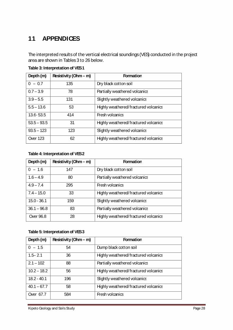
11 APPENDICES
The interpreted results of the vertical electrical soundings (VES) conducted in the project area are shown in Tables 3 to 26 below.
Table 3: Interpretation of VES 1
Depth (m) Resistivity (Ohm – m) Formation
0 – 0.7 135 Dry black cotton soil
0.7 – 3.9 78 Partially weathered volcanics
3.9 – 5.5 131 Slightly weathered volcanics
5.5 – 13.6 53 Highly weathered/fractured volcanics
13.6- 53.5 414 Fresh volcanics
53.5 – 93.5 31 Highly weathered/fractured volcanics
93.5 – 123 123 Slightly weathered volcanics
Over 123 62 Highly weathered/fractured volcanics
Table 4: Interpretation of VES 2
Depth (m) Resistivity (Ohm – m) Formation
0 – 1.6 147 Dry black cotton soil
1.6 – 4.9 80 Partially weathered volcanics
4.9 – 7.4 295 Fresh volcanics
7.4 – 15.0 33 Highly weathered/fractured volcanics
15.0 - 36.1 159 Slightly weathered volcanics
36.1 – 96.8 83 Partially weathered volcanics
Over 96.8 28 Highly weathered/fractured volcanics
Table 5: Interpretation of VES 3
Depth (m) Resistivity (Ohm – m) Formation
0 – 1.5 54 Dump black cotton soil
1.5– 2.1 36 Highly weathered/fractured volcanics
2.1 – 102 88 Partially weathered volcanics
10.2 – 18.2 56 Highly weathered/fractured volcanics
18.2 - 40.1 196 Slightly weathered volcanics
40.1 – 67.7 58 Highly weathered/fractured volcanics
Over 67.7 584 Fresh volcanics

KipetoGeologyandSoilsStudy Page29
Table 6: Interpretation of VES 4
Depth (m) Resistivity (Ohm – m) Formation
0 – 1.3 47 Dump black cotton soil
1.3– 2.1 113 Slightly weathered volcanics
2.1 – 3.2 56 Highly weathered/fractured volcanics
3.2 – 9.7 160 Slightly weathered volcanics
9.7 - 16.5 91 Partially weathered volcanics
16.5 – 51.1 271 Fresh volcanics
Over 51.1 29 Highly weathered/fractured volcanics
Table 7: Interpretation of VES 5
Depth (m) Resistivity (Ohm – m) Formation
0 – 1.5 171 Dry black cotton soil
1.5– 8.0 39 Highly weathered/fractured volcanics
8.0 – 15.8 60 Partially weathered volcanics
15.8 – 30.7 16 Highly weathered/fractured volcanics
Over 30.7 62 Partially weathered volcanics
Table 8: Interpretation of VES 6
Depth (m) Resistivity (Ohm – m) Formation
0 – 1.3 153 Dry black cotton soil
1.3– 6.4 90 Partially weathered volcanics
6.4 – 20.7 225 Fresh volcanics
20.7 – 38.5 46 Highly weathered/fractured volcanics
38.5 – 62.9 190 Fresh volcanics
62.7- 107.4 56 Partially weathered volcanics
Over 107.4 131 Slightly weathered volcanics
Table 9: Interpretation of VES 7
Depth (m) Resistivity (Ohm – m) Formation
0 – 0.8 144 Dry black cotton soil
0.8– 2.6 55 Weathered volcanics
2.6 – 3.5 108 Slightly weathered volcanics
3.5 – 9.2 22 Highly weathered/fractured volcanics
9.2 - 26.4 248 Fresh volcanics
KipetoGeologyandSoilsStudy Page30
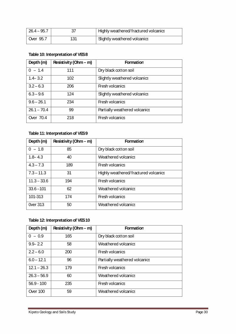
26.4 – 95.7 37 Highly weathered/fractured volcanics
Over 95.7 131 Slightly weathered volcanics
Table 10: Interpretation of VES 8
Depth (m) Resistivity (Ohm – m) Formation
0 – 1.4 111 Dry black cotton soil
1.4– 3.2 102 Slightly weathered volcanics
3.2 – 6.3 206 Fresh volcanics
6.3 – 9.6 124 Slightly weathered volcanics
9.6 – 26.1 234 Fresh volcanics
26.1 – 70.4 99 Partially weathered volcanics
Over 70.4 218 Fresh volcanics
Table 11: Interpretation of VES 9
Depth (m) Resistivity (Ohm – m) Formation
0 – 1.8 85 Dry black cotton soil
1.8– 4.3 40 Weathered volcanics
4.3 – 7.3 189 Fresh volcanics
7.3 – 11.3 31 Highly weathered/fractured volcanics
11.3 – 33.6 194 Fresh volcanics
33.6 –101 62 Weathered volcanics
101-313 174 Fresh volcanics
0ver 313 50 Weathered volcanics
Table 12: Interpretation of VES 10
Depth (m) Resistivity (Ohm – m) Formation
0 – 0.9 165 Dry black cotton soil
9.9– 2.2 58 Weathered volcanics
2.2 – 6.0 200 Fresh volcanics
6.0 – 12.1 96 Partially weathered volcanics
12.1 – 26.3 179 Fresh volcanics
26.3 – 56.9 60 Weathered volcanics
56.9 - 100 235 Fresh volcanics
Over 100 59 Weathered volcanics
KipetoGeologyandSoilsStudy Page31
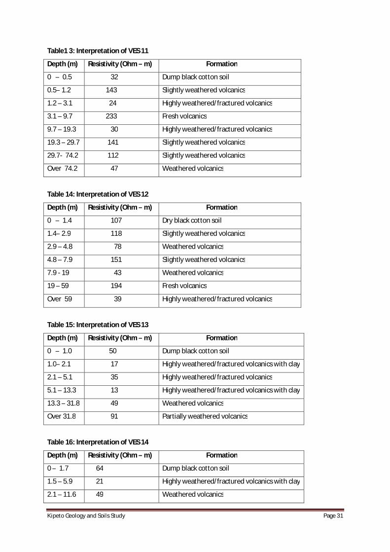
Table1 3: Interpretation of VES 11
Depth (m) Resistivity (Ohm – m) Formation
0 – 0.5 32 Dump black cotton soil
0.5– 1.2 143 Slightly weathered volcanics
1.2 – 3.1 24 Highly weathered/fractured volcanics
3.1 – 9.7 233 Fresh volcanics
9.7 – 19.3 30 Highly weathered/fractured volcanics
19.3 – 29.7 141 Slightly weathered volcanics
29.7- 74.2 112 Slightly weathered volcanics
Over 74.2 47 Weathered volcanics
Table 14: Interpretation of VES 12
Depth (m) Resistivity (Ohm – m) Formation
0 – 1.4 107 Dry black cotton soil
1.4– 2.9 118 Slightly weathered volcanics
2.9 – 4.8 78 Weathered volcanics
4.8 – 7.9 151 Slightly weathered volcanics
7.9 - 19 43 Weathered volcanics
19 – 59 194 Fresh volcanics
Over 59 39 Highly weathered/fractured volcanics
Table 15: Interpretation of VES 13
Depth (m) Resistivity (Ohm – m) Formation
0 – 1.0 50 Dump black cotton soil
1.0– 2.1 17 Highly weathered/fractured volcanics with clay
2.1 – 5.1 35 Highly weathered/fractured volcanics
5.1 – 13.3 13 Highly weathered/fractured volcanics with clay
13.3 – 31.8 49 Weathered volcanics
Over 31.8 91 Partially weathered volcanics
Table 16: Interpretation of VES 14
Depth (m) Resistivity (Ohm – m) Formation
0 – 1.7 64 Dump black cotton soil
1.5 – 5.9 21 Highly weathered/fractured volcanics with clay
2.1 – 11.6 49 Weathered volcanics

KipetoGeologyandSoilsStudy Page32
10.2 – 20.2 17 Highly weathered/fractured volcanics with clay
18.2 – 68.1 88 Partially weathered volcanics
Over 68.1 25 Highly weathered/fractured volcanics with clay
Table 17: Interpretation of VES 15
Depth (m) Resistivity (Ohm – m) Formation
0 – 0.6 9 Clayey and dump black cotton soil
0.6– 3.7 43 Weathered volcanics
3.7 – 10.1 22 Highly weathered/fractured volcanics with clay
10.1 – 89.4 134 Slightly weathered volcanics
Over 89.4 45 Weathered volcanics
Table 18: Interpretation of VES 16
Depth (m) Resistivity (Ohm – m) Formation
0 – 2.9 96 Dry black cotton soil
2.9– 4.6 43 Weathered volcanics
4.6 – 11.4 139 Slightly weathered volcanics
11.4 – 14.0 50 Weathered volcanics
14.0 – 40.7 118 Slightly weathered volcanics
40.7 -73.6 42 Weathered volcanics
73.6- 117.9 166 Slightly weathered volcanics
Over 117.9 68 Weathered volcanics
Table 19: Interpretation of VES 17
Depth (m) Resistivity (Ohm – m) Formation
0 – 1.1 49 Dump black cotton soil
1.5– 4.0 15 Highly weathered/fractured volcanics with clay
2.1 – 12.6 96 Partially weathered volcanics
10.2 – 25.9 28 Highly weathered/fractured volcanics
18.2 – 61.6 227 Fresh volcanics
40.1 – 87.9 43 Weathered volcanics
Over 87.9 122 Slightly weathered volcanics

KipetoGeologyandSoilsStudy Page33
Table 20: Interpretation of VES 18
Depth (m) Resistivity (Ohm – m) Formation
0 – 1.2 40 Dump black cotton soil
1.2– 2.8 22 Highly weathered/fracture volcanics
2.8 – 4.5 84 Partially weathered volcanics
4.5 – 10.7 14 Highly weathered/fractured volcanics with clay
10.7 – 20 126 Slightly weathered volcanics
20 – 23 40 Weathered volcanics
23 - 52.6 140 Slightly weathered volcanics
Over 52.6 16 Highly weathered/fractured volcanics with clay
Table 21: Interpretation of VES 19
Depth (m) Resistivity (Ohm – m) Formation
0 – 1.3 41 Dump black cotton soil
1.3– 2.6 25 Highly weathered/fractured volcanics
2.6 – 6.7 51 Weathered volcanics
6.7 – 10.9 39 Highly weathered/fracture volcanics
10.9 – 26.9 310 Fresh volcanics
Over 26.9 22 Highly weathered/fractured volcanics with clay
Table 22: Interpretation of VES 20
Depth (m) Resistivity (Ohm – m) Formation
0 – 0.9 50 Dump black cotton soil
0.9– 2.4 19 Highly weathered/fractured volcanics with clay
2.4 – 7.0 48 Weathered volcanics
7.0 – 14.0 16 Highly weathered/fractured volcanics with clay
14.0 – 30.0 66 Weathered volcanics
30.0 – 64.6 14 Highly weathered/fracture volcanics with clay
Over 64.6 61 Weathered volcanics
Table 23: Interpretation of VES 21
Depth (m) Resistivity (Ohm – m) Formation
0 – 0.6 34 Dump black cotton soil
1.5– 2.0 138 Slightly weathered volcanics
2.1 – 3.0 42 Weathered volcanics
KipetoGeologyandSoilsStudy Page34
3.0 – 5.7 213 Fresh volcanics
5.7 – 10.2 118 Slightly weathered volcanics
10.2 – 21.3 199 Fresh volcanics
21.3- 39.7 105 Slightly weathered volcanics
39.7-99.4 177 Fresh volcanics
99.4-161 101 Slightly weathered volcanics
Over 161 164 Slightly weathered volcanics
Table 24: Interpretation of VES 22
Depth (m) Resistivity (Ohm – m) Formation
0 – 1.0 70 Dump black cotton soil
1.5– 3.2 29 Highly weathered/fracture volcanics
2.1 – 5.4 39 Weathered volcanics
10.2 – 11.4 14 Highly weathered/fractured volcanics with clay
Over 11.4 143 Slightly weathered volcanics
Table 25: Interpretation of VES 23
Depth (m) Resistivity (Ohm – m) Formation
0 – 1.7 118 Dry black cotton soil
1.7– 4.3 251 Fresh volcanics
4.3 – 10.5 143 Slightly weathered volcanics
10.5 – 17.3 396 Fresh volcanics
17.3 – 27.2 198 Fresh volcanics
27.2 – 65.4 339 Fresh volcanics
Over 65.4 115 Slightly weathered volcanics
Table 26: Interpretation of VES 24
Depth (m) Resistivity (Ohm – m) Formation
0 – 1.5 47 Dump black cotton soil
1.5– 3.0 44 Weathered volcanics
3.0 – 5.5 105 Slightly weathered volcanics
5.5 – 13.3 34 Highly weathered/fractured volcanics
13.3 – 46.3 402 Fresh volcanics
Over 46.3 51 Weathered volcanics
KipetoGeologyandSoilsStudy Page35
12 PICTURESOFSOMECAVESENCOUNTEREDINTHEPROJECTAREA
Figure 3: Cave no. 012
Figure 4: Cave no. 018
KipetoGeologyandSoilsStudy Page36
Figure 5: Cave no. 019
Figure 6: Cave no. 026
KipetoGeologyandSoilsStudy Page37
Figure 7: Cave no. 33