Geog 495 GIS Database Design Midterm review. Outlines 1.Database Concepts 2.Relational Database...
45
Geog 495 GIS Database Design Midterm review
-
Upload
bethany-pope -
Category
Documents
-
view
233 -
download
2
Transcript of Geog 495 GIS Database Design Midterm review. Outlines 1.Database Concepts 2.Relational Database...
Geog 495GIS Database Design
Midterm review
Outlines
1. Database Concepts
2. Relational Database
3. Object-oriented Database
4. Entity-Relationship Diagram
5. Unified Modeling Language
6. Normalization
1. Database concepts
• Data vs. Information
• Data vs. Database
• DBMS vs. Database system
• Level of abstraction
• Data independence
• Different database models
• Architecture of database system

Data vs. Information
• Data: raw fact
• Information: data processed to reveal meaning
• Database system transforms data into information through queries
Data vs. Database
• Database is a collection of related data
• Database stores data in an organized manner (i.e. minimal data redundancy)
• Database exists, first and the foremost, to serve users’ requirements
DBMS vs. DB system
• DBMS allows users to access data (i.e. interface between users and database)
• DB system is composed of DBMS, people, database, and procedures
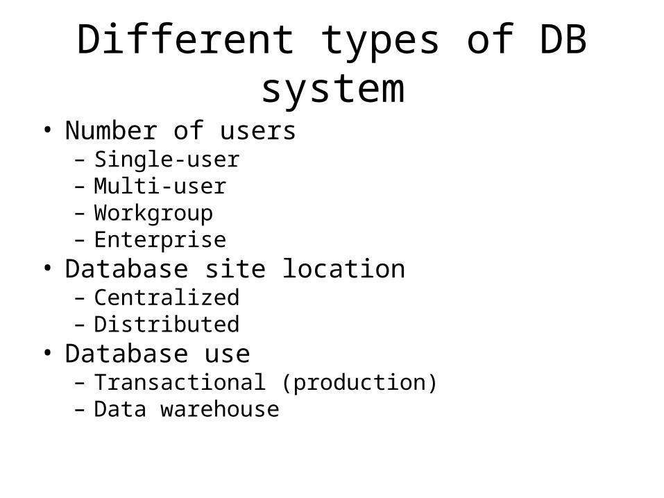
Different types of DB system
• Number of users– Single-user– Multi-user– Workgroup– Enterprise
• Database site location– Centralized– Distributed
• Database use– Transactional (production)– Data warehouse
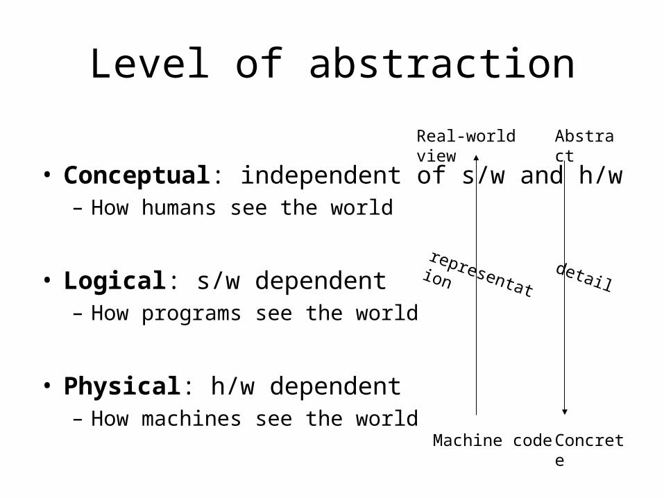
Level of abstraction
• Conceptual: independent of s/w and h/w– How humans see the world
• Logical: s/w dependent– How programs see the world
• Physical: h/w dependent– How machines see the world
Real-world view
Machine code
Abstract
Concrete
representationdetail
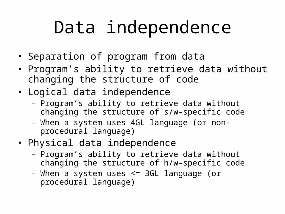
Data independence
• Separation of program from data• Program’s ability to retrieve data without changing the
structure of code• Logical data independence
– Program’s ability to retrieve data without changing the structure of s/w-specific code
– When a system uses 4GL language (or non-procedural language)
• Physical data independence– Program’s ability to retrieve data without changing the structure
of h/w-specific code– When a system uses <= 3GL language (or procedural language)
Database models
• Hierarchical
• Network
• Relational
• Object-oriented
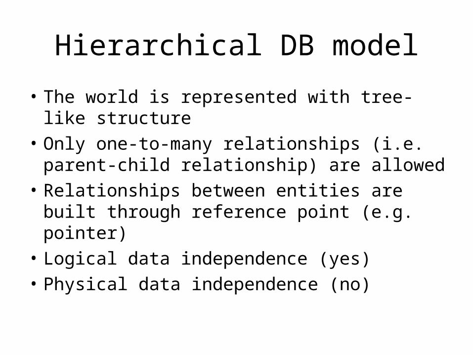
Hierarchical DB model
• The world is represented with tree-like structure
• Only one-to-many relationships (i.e. parent-child relationship) are allowed
• Relationships between entities are built through reference point (e.g. pointer)
• Logical data independence (yes)
• Physical data independence (no)

Network DB model
• The world is represented with web-like structure
• Many-to-many relationships are allowed
• Relationships between entities are built through reference point (e.g. pointer)
• Logical data independence (yes)
• Physical data independence (no)
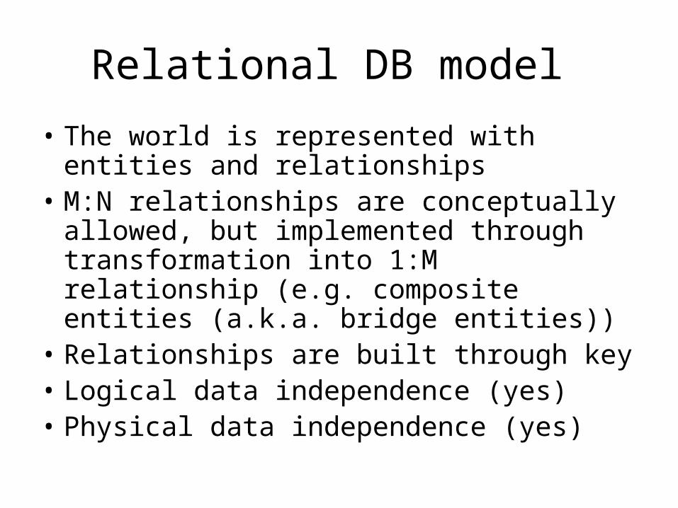
Relational DB model
• The world is represented with entities and relationships
• M:N relationships are conceptually allowed, but implemented through transformation into 1:M relationship (e.g. composite entities (a.k.a. bridge entities))
• Relationships are built through key• Logical data independence (yes)• Physical data independence (yes)
Object-oriented DB model
• The world is represented with a collection of objects
• Object embeds attribute, operation and relationships
• Complex objects can be represented through abstract data type
• Embody OO concepts such as encapsulation, inheritance and polymorphism

Architecture of DB system
1. External viewuser’s view, local (incomplete)
2. Conceptual/logical viewdesigner’s view, global
3. Internal viewProgrammer’s view
• Physical viewImplementation view, contains most details
• Organized by level of abstraction• Data independence is embodied by the proper
separation between four layers

2. Relational DB
• Representation
• Table
• Key
• Integrity rules
• Relationships
Representation
• The world are viewed as entities and relationships
• Entities are modeled as table
• Relationships are built through common attributes between entities
Table
• Row represents a single entity
• Column represents attribute
• Cell represents a single value in the intersection between row and column
Key
• One or more attributes (columns) that determines other attributes
• Primary key– Uniquely identifies entity (should be unique)– Should be Not Null (non-empty)
• Foreign key– Common attributes that link one table to another
tables– Placed in M side table in reference to primary key to 1
side table
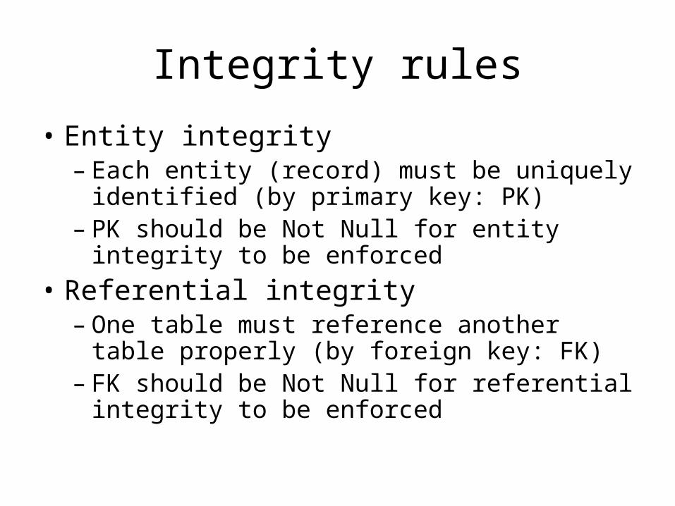
Integrity rules
• Entity integrity– Each entity (record) must be uniquely
identified (by primary key: PK)– PK should be Not Null for entity integrity to be
enforced
• Referential integrity– One table must reference another table
properly (by foreign key: FK)– FK should be Not Null for referential integrity
to be enforced
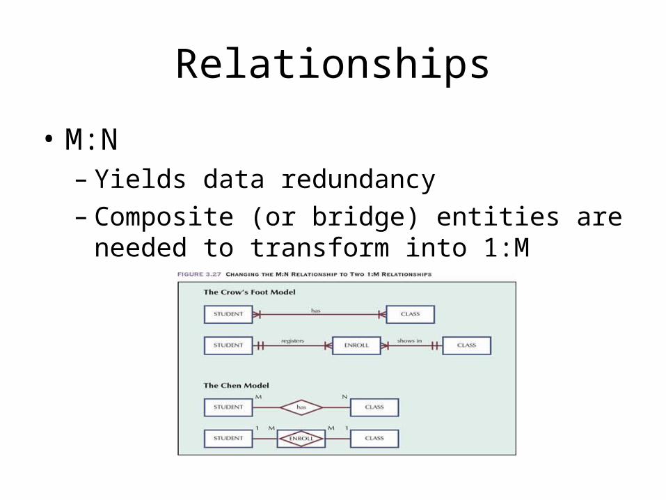
Relationships
• M:N– Yields data redundancy– Composite (or bridge) entities are needed to
transform into 1:M
3. Object-oriented DB
• Object
• Difference between object in OODB and entity in RDB
• Object and class
• OO concepts
Object
• Object has– OID (identity): system-generated– Instance variables (attributes): ADT allowed,
thus the representation of complex entities are possible
– Methods (operations): make objects act upon them, thus entities become autonomous

Objects (OODB) vs. Entities (RDB)
Objects, unlike entities• Identity is not state-dependent
– Because OID is system-generated
• Relationship is embedded in the object– Because objects store the reference to other
objects in themselves
• Autonomous – Because objects can use methods stored in
class

Object and Class
• Class is a collection of objects with similar attributes and behaviors
• Object is an instance of class from conceptual point of view
• Class is an instantiation of objects from implementation point of view (i.e. Object is implemented through class: e.g. object uses the methods stored in class)
• Objects are organized by class hierarchy
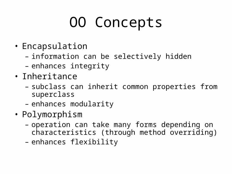
OO Concepts
• Encapsulation– information can be selectively hidden – enhances integrity
• Inheritance– subclass can inherit common properties from
superclass – enhances modularity
• Polymorphism– operation can take many forms depending on
characteristics (through method overriding) – enhances flexibility
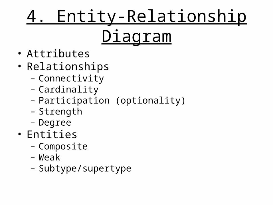
4. Entity-Relationship Diagram
• Attributes• Relationships
– Connectivity– Cardinality– Participation (optionality)– Strength– Degree
• Entities– Composite– Weak– Subtype/supertype
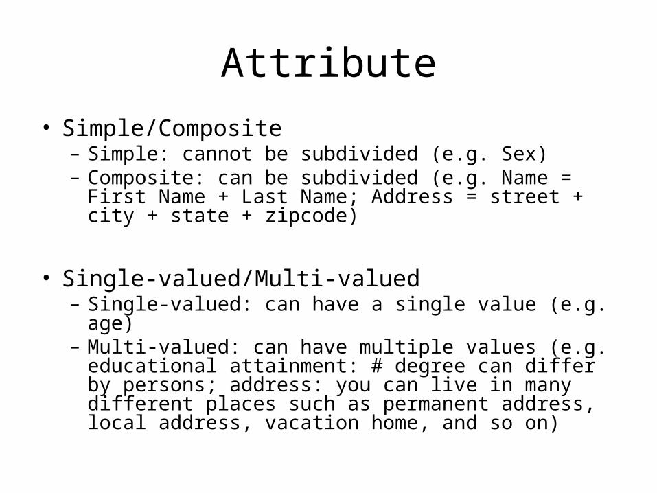
Attribute
• Simple/Composite– Simple: cannot be subdivided (e.g. Sex)– Composite: can be subdivided (e.g. Name = First
Name + Last Name; Address = street + city + state + zipcode)
• Single-valued/Multi-valued– Single-valued: can have a single value (e.g. age) – Multi-valued: can have multiple values (e.g.
educational attainment: # degree can differ by persons; address: you can live in many different places such as permanent address, local address, vacation home, and so on)

Relationships
• Connectivity: 1:1, 1:M, M:N• Cardinalities: the number of entity
occurrence associated with another entity• Participation: optional/mandatory,
determined by cardinalities• Strength: existence-dependency + PK
derived from other table• Degree: the number of entities associated
with the relationship
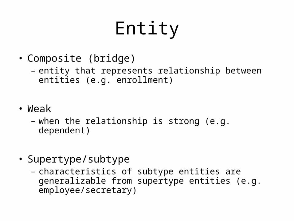
Entity
• Composite (bridge)– entity that represents relationship between entities
(e.g. enrollment)
• Weak– when the relationship is strong (e.g. dependent)
• Supertype/subtype– characteristics of subtype entities are generalizable
from supertype entities (e.g. employee/secretary)
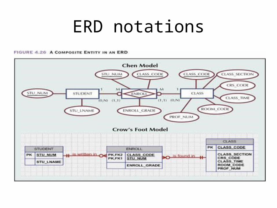
ERD notations

5. UML
• What is UML?
• Why UML?
• UML Diagrams
• Class Diagram
What is UML?
• Standardized modeling language for OO system design & analysis
• UML notation 1.0 was formed in 1996, version 2.0 as of 2005
• Graphic notations: in between natural language (too imprecise) and programming language (too precise thus too much details)
• Use different diagrams depending on different perspectives (conceptual, logical, physical)
Why UML?
• Let’s make OO system design unified• Let’s make OO system design visual and easy-
to-learn• Let’s make OO system design independent of
different programming languages• Let’s promote good things about OO principles
– Modularity/code reusability• Let’s make system extensible
– Stereotype, tagged value, constraint• Let’s make model interchange easier
– XMI (XML Modeling Interchange)
UML Diagrams
• Behavior diagram– Describe behavioral aspect of system– Use case diagram, activity diagram
• Structure diagram– Show the static structure of the model– Class diagram, package diagram– Component diagram, deployment diagram
• Interaction diagram– Represents different aspects of interaction– Sequence diagram, collaboration diagram
Class Diagram (overview)
• Shows the static structure of object-oriented database or database that is implemented in OO system
• Equivalent to ERD with some differences such as operation and more semantics on relationships
• Can be seen from three different perspectives (conceptual, specification, implementation)
Class Diagram: class
• Class is represented as three-part compartments (name, attribute, operation)
• Naming notation of attribute – [visibility] name: data type = [initial-value]
• Naming notation of operations– [visibility] name (parameter-list: data type):
[return value type]
Class Diagram: relationship
• Association• Aggregation: part-whole relation• Composition: strong form of aggregation• Generalization: general/unique properties• Dependency: implementation of one class is
dependent on another class
• Multiplicities: # participants associated with relationship
• Navigability: shows the direction of navigation between classes
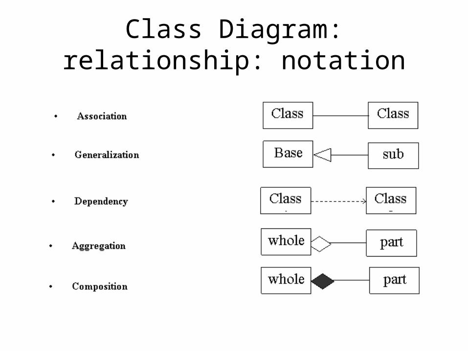
Class Diagram: relationship: notation

6. Normalization
• What is normalization?
• 1NF
• 2NF
• 3NF

What is normalization?
• Process for correcting table structure to minimize data redundancies
• Usually follows three-step procedures: conversion 1NF 2NF 3NF
• Operated by functional dependency between attributes
• Two types of functional dependencies– Partial dependency: nonkey attributes are dependent
on a part of composite PK– Transitive dependency: nonkey attributes are
dependent on another nonkey attributes

First Normal Form (1NF)
• No repeating groups
• PK is defined
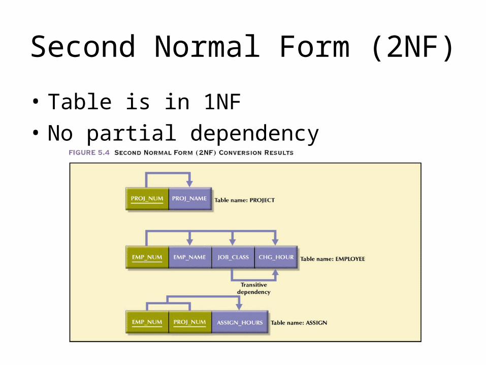
Second Normal Form (2NF)
• Table is in 1NF
• No partial dependency
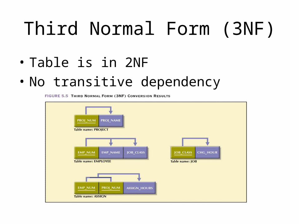
Third Normal Form (3NF)
• Table is in 2NF
• No transitive dependency

Questions & concerns?
• Please talk to me
• Take advantage of office hours (Wed 2:30-4:30): tutorial is the best way to communicate I believe.
• Please do some reading before you show up in the class.