Geodesy, Map Projections and Coordinate Systems Geodesy - the shape of the earth and definition of...
83
Geodesy, Map Projections and Coordinate Systems • Geodesy - the shape of the earth and definition of earth datums • Map Projection - the transformation of a curved earth to a flat map • Coordinate systems - (x,y,z) coordinate systems for map data Instructor: Dr. Ayse Kilic Civil Engineering and School of Natural Resources University of Nebraska *Some of the slide material is adapted from from Dr. David Maidment of the University of Texas and Dr. David Tarboton of Utah State University
-
Upload
hubert-fleming -
Category
Documents
-
view
234 -
download
5
Transcript of Geodesy, Map Projections and Coordinate Systems Geodesy - the shape of the earth and definition of...

Geodesy, Map Projections and Coordinate Systems
• Geodesy - the shape of the earth and definition of earth datums
• Map Projection - the transformation of a curved earth to a flat map
• Coordinate systems - (x,y,z) coordinate systems for map data
Instructor: Dr. Ayse KilicCivil Engineering and School of Natural Resources
University of Nebraska*Some of the slide material is adapted from from Dr. David Maidment of the University of Texas and Dr. David Tarboton of Utah State University
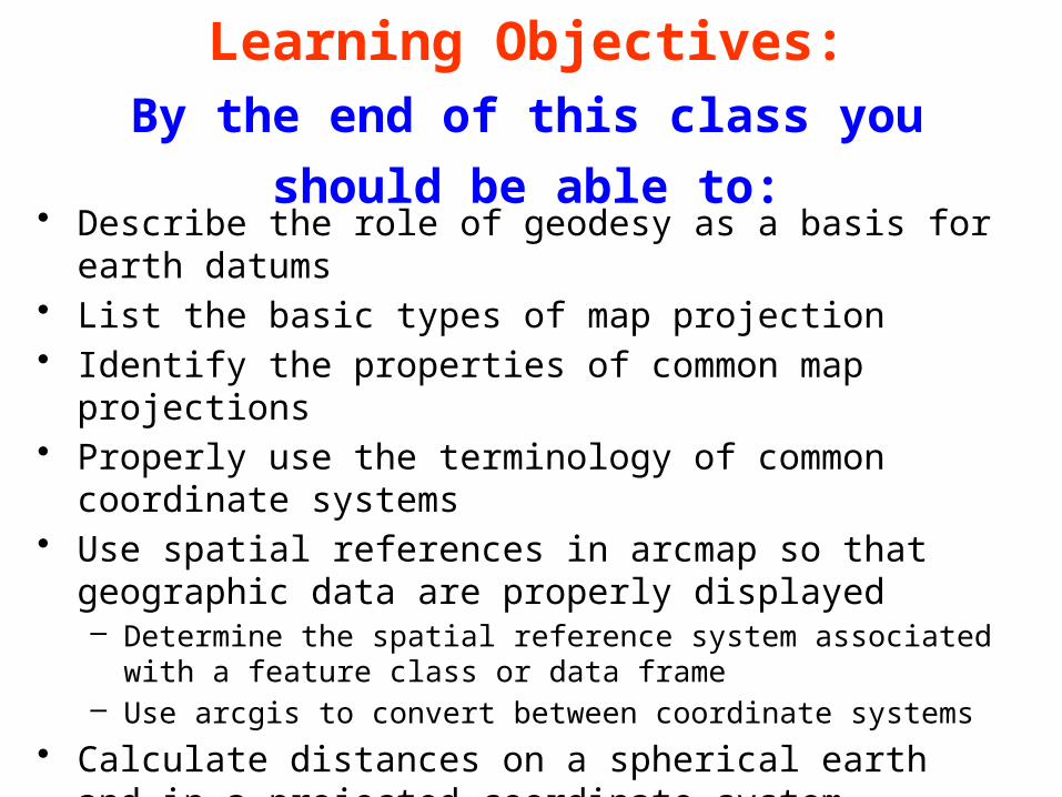
Learning Objectives:By the end of this class you should be able to:
• Describe the role of geodesy as a basis for earth datums• List the basic types of map projection• Identify the properties of common map projections• Properly use the terminology of common coordinate systems• Use spatial references in arcmap so that geographic data are
properly displayed– Determine the spatial reference system associated with a feature class or
data frame– Use arcgis to convert between coordinate systems
• Calculate distances on a spherical earth and in a projected coordinate system
3
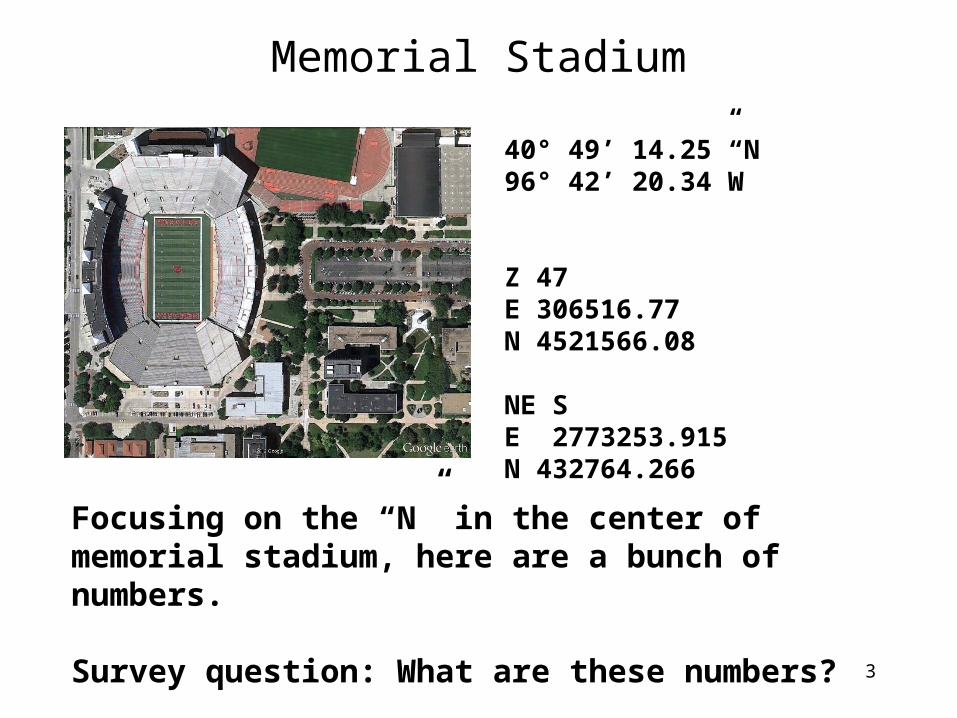
Memorial Stadium
40° 49’ 14.25” N96° 42’ 20.34”W
Z 47E 306516.77N 4521566.08
NE SE 2773253.915 N 432764.266
Focusing on the “N” in the center of memorial stadium, here are a bunch of numbers.
Survey question: What are these numbers?

Memorial Stadium
4
40° 49’ 14.25” N96° 42’ 20.34”W
Z 47E 306516.77N 4521566.08
NE SE 2773253.915 N 432764.266
Global Coordinate System
(Latitude/Longitude)
Universal Transverse
Mercator (UTM)
State Plane Coordinate
System (SPCS) Nebraska South
They all point to the same place, but they have different referencesWe’re going to talk about what those numbers mean and what they do for us

Readings: Introductionhttp://resources.arcgis.com/en/help/getting-started/articles/026n0000000s000000.htm
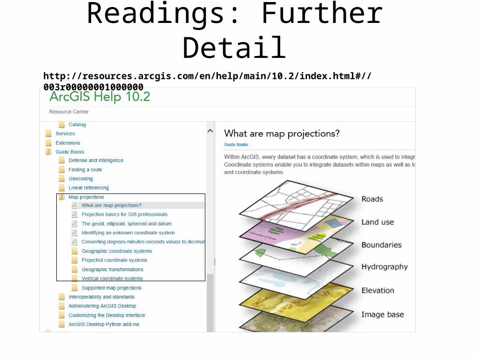
Readings: Further Detailhttp://resources.arcgis.com/en/help/main/10.2/index.html#//003r00000001000000

7
History on maps
Ancient “Globe”Sun and stars rotating about “Island Earth”
The oldest known maps are preserved on Babylonian Clay Tablets from about 600 B.C.
Greek world view 300 BC
150 BC – Hipparchus of Rhodes invented the concept of Lat/Long
Ptolemaic world 150 AD(1493 depiction)
Mercator’s Map-1569 AD• Cylindrical projection – putting
a round globe onto a piece of paper with meaningful accuracy
• Medieval Maps
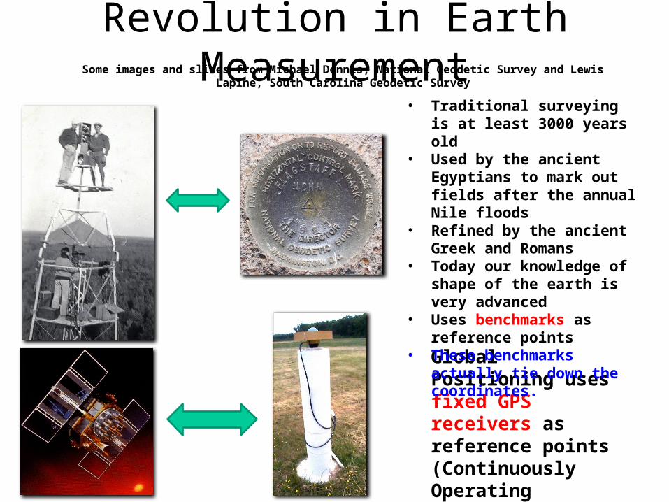
Revolution in Earth Measurement
Global Positioning uses fixed GPS receivers as reference points (Continuously Operating Reference System, CORS)
Some images and slides from Michael Dennis, National Geodetic Survey and Lewis Lapine, South Carolina Geodetic Survey
• Traditional surveying is at least 3000 years old
• Used by the ancient Egyptians to mark out fields after the annual Nile floods
• Refined by the ancient Greek and Romans
• Today our knowledge of shape of the earth is very advanced
• Uses benchmarks as reference points
• These benchmarks actually tie down the coordinates.

HOW ACCURATE CAN WE KNOW A LOCATION? (and is it static?)
If we really want to know the location very accurately, we have to appreciate every point on the earth is moving because of tectonic plates.
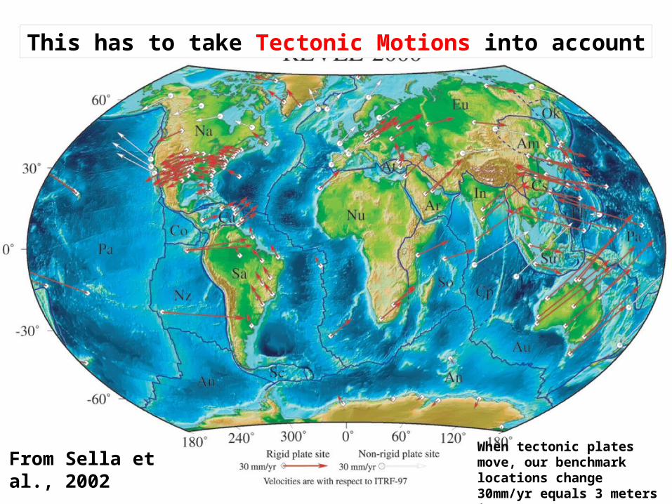
Tectonic Motions
From Sella et al., 2002
This has to take Tectonic Motions into account
When tectonic plates move, our benchmark locations change30mm/yr equals 3 meters in 100 years

HORIZONTAL TECTONIC MOTIONS
Pacific Plate
North American Plate
Motion in cm/year
When is California not in North America … …. when its on the Pacific Plate!

{Latitude (f), Longitude (l), Elevation (z)}
Survey Benchmark
This leads to adjustments in locations of the national network of survey benchmarks
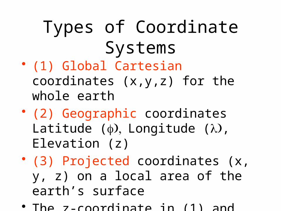
Types of Coordinate Systems
• (1) Global Cartesian coordinates (x,y,z) for the whole earth
• (2) Geographic coordinates Latitude ( ), fLongitude ( )l , Elevation (z)
• (3) Projected coordinates (x, y, z) on a local area of the earth’s surface
• The z-coordinate in (1) and (3) is defined geometrically; in (2) the z-coordinate is defined gravitationally
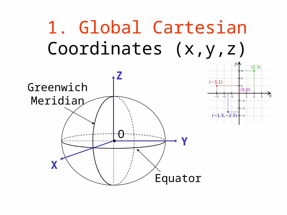
1. Global Cartesian Coordinates (x,y,z)
O
X
Z
Y
GreenwichMeridian
Equator
•
Spatial Reference = Datum + Projection + Coordinate system
• For consistent analysis the spatial reference of data sets should be the same.
• ArcGIS does projection on the fly so it can display data with different spatial references properly if they are properly specified. (but it is “safest” if all layers are in the same projection)– Earth datums define standard values of the ellipsoid and geoid– Different datums use different estimates for the precise shape and
size of the Earth (reference ellipsoids).
• ArcGIS terminology– Define projection. Specify the projection for some data without
changing the data.– Project. Change the data from one projection to another.
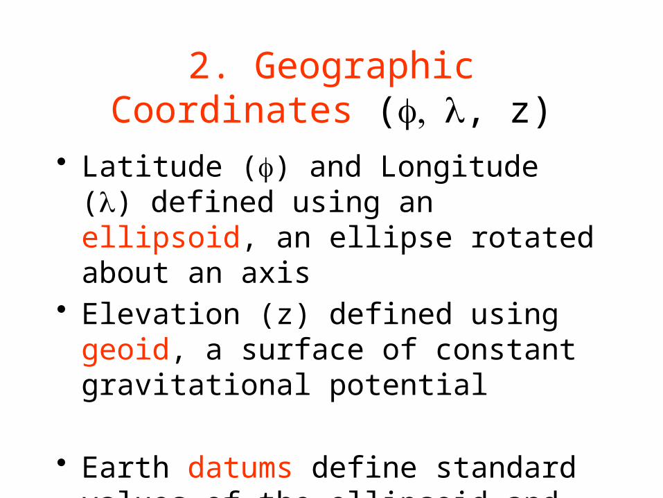
2. Geographic Coordinates ( , f l, z)
• Latitude (f) and Longitude (l) defined using an ellipsoid, an ellipse rotated about an axis
• Elevation (z) defined using geoid, a surface of constant gravitational potential
• Earth datums define standard values of the ellipsoid and geoid

GEOID
• The geoid is the shape that the surface of the oceans would take under the influence of Earth's gravitation and rotation alone, in the absence of other influences such as winds and tides.
• All points on the geoid have the same gravitational potential. • The force of gravity acts everywhere perpendicular to the geoid, meaning that
plumb lines point perpendicular and water levels parallel to the geoid.
• Geoid is mean sea level at a particular point and varies with gravitational potential
• Geoid is where mean sea level would be if there was an ocean at that location
• Geoid elevation is usually below the land surface

Shape of the Earth
We think of the earth as a sphere
It is actually a spheroid, slightly larger in radius at
the equator than at the poles
The earth is not round!
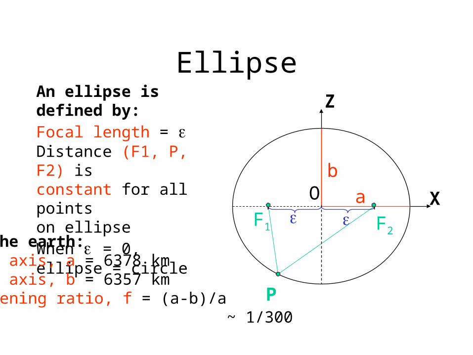
Ellipse
P
F2
O
F1
a
b
X
Z
An ellipse is defined by:Focal length = Distance (F1, P, F2) isconstant for all pointson ellipseWhen = 0, ellipse = circle
For the earth:Major axis, a = 6378 kmMinor axis, b = 6357 kmFlattening ratio, f = (a-b)/a ~ 1/300

Ellipsoid or SpheroidRotate an ellipse around an axis
O
X
Z
Ya ab
Rotational axis
An Ellipse is 2 dimensionalA Spheroid is 3 dimensional
The X, Y, and Z axes are at 90 degree angles to each other

Standard Ellipsoids
Ellipsoid Majoraxis, a (m)
Minoraxis, b (m)
Flatteningratio, f
Clarke(1866)
6,378,206 6,356,584 1/294.98
GRS80 6,378,137 6,356,752 1/298.57
Ref: Snyder, Map Projections, A working manual, USGSProfessional Paper 1395, p.12

Geodetic Datums• World Geodetic System (WGS) – is a global system for
defining latitude (f) and longitude (l) on earth and does not change even with tectonic movement (military).Therefore, latitude and longitude coordinates of a point in Lincoln will change with time if Lincoln moves.
• North American Datum (NAD) – is a system defined for locating fixed objects on the earth’s surface and includes tectonic movement (civilian) (Everything is moving). Therefore, latitude and longitude coordinates of a point in Lincoln will not change with time if Lincoln moves.
• Lincoln (40.8106° N, 96.6803° W)
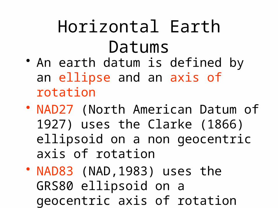
Horizontal Earth Datums• An earth datum is defined by an ellipse and
an axis of rotation• NAD27 (North American Datum of 1927)
uses the Clarke (1866) ellipsoid on a non geocentric axis of rotation
• NAD83 (NAD,1983) uses the GRS80 ellipsoid on a geocentric axis of rotation
• WGS84 (World Geodetic System of 1984) uses GRS80, almost the same as NAD83

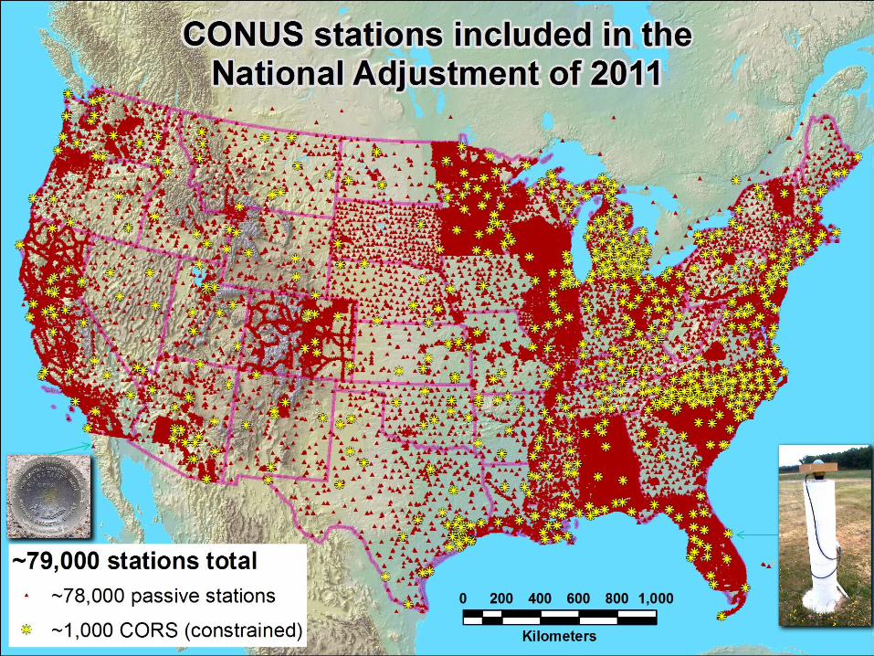
Adjustments of the NAD83 Datum
Slightly different (f, l) for benchmarks
Continuously Operating Reference SystemCanadian Spatial Reference SystemNational Spatial Reference SystemHigh Accuracy Reference Network

Representations of the Earth
Earth surface
EllipsoidSea surface
Geoid
Mean Sea Level is a surface of constant gravitational potential called the Geoid

THE GEOID AND TWO ELLIPSOIDS
GRS80-WGS84(NAD83)
CLARKE 1866 (NAD27)
GEOID
Earth Mass Center
Approximately 236 meters
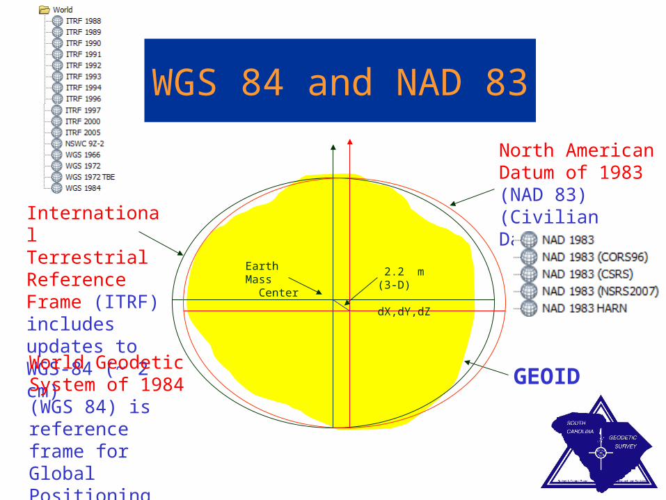
WGS 84 and NAD 83
International Terrestrial Reference Frame (ITRF) includes updates to WGS-84 (~ 2 cm)
North American Datum of 1983 (NAD 83) (Civilian Datum of US)
Earth Mass Center
2.2 m (3-D) dX,dY,dZ
GEOIDWorld Geodetic System of 1984 (WGS 84) is reference frame for Global Positioning Systems

Latitude ( ) & f Longitude ( ) l

Strict definition of Latitude, f
(1) Take a point S on the surface of the ellipsoid and define there the tangent plane, mn(2) Define the line pq through S and normal to thetangent plane(3) Angle pqr which this line makes with the equatorialplane is the latitude f, of point S
O f
Sm
nq
p
r

Cutting Plane of a Meridian
P
Meridian
Equator
plane
Prime Meridian

Definition of Longitude, l
0°E, W
90°W(-90 °)
180°E, W
90°E(+90 °)
-120°
-30°
-60°
-150°
30°
-60°
120°
150°
l
l = the angle between a cutting plane on the prime meridianand the cutting plane on the meridian through the point, P
P

Latitude and Longitude on a Sphere
Meridian of longitude
Parallel of latitude
X
Y
ZN
EW
=0-
90°S
P
OR
=0-180°E
=0-90°N
•
Greenwichmeridian
=0°
•
Equator =0°
•
•=0-180°W
- Geographic longitude - Geographic latitude
R - Mean earth radius
O - Geocenter
Length on Meridians and Parallels
0 N
30 N
DfRe
Re
RR
A
BC
Dl
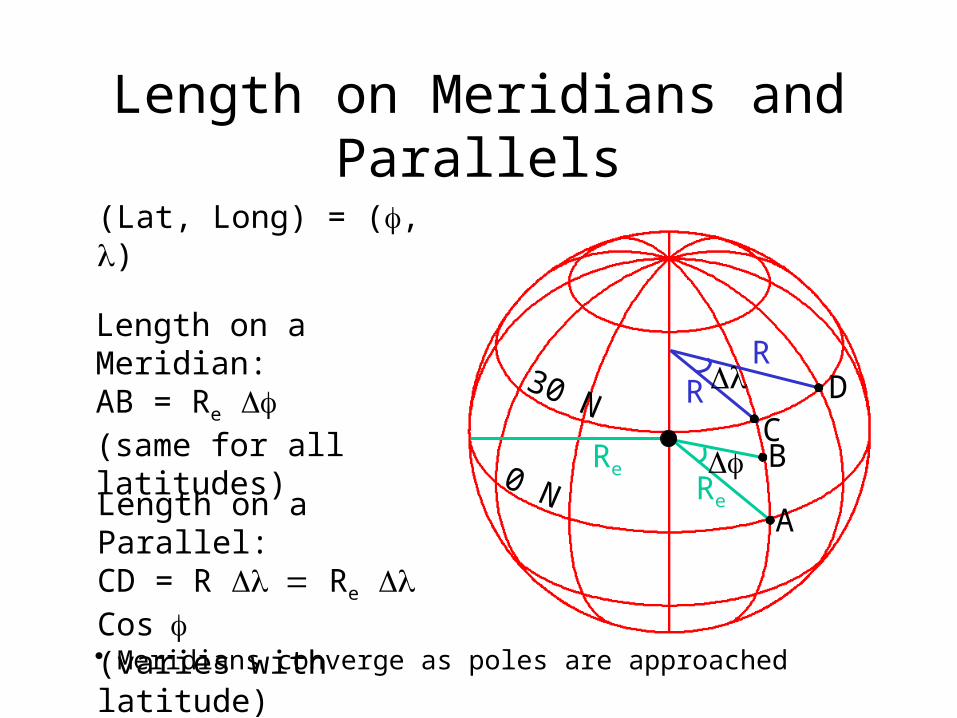
(Lat, Long) = (f, l)
Length on a Meridian:AB = Re Df(same for all latitudes)
Length on a Parallel:CD = R =Dl Re Dl Cos f(varies with latitude)
D
• Meridians converge as poles are approached

Example: What is the length of a 1º increment along on a meridian and on a parallel at 30N, 90W?Radius of the earth = 6370 km.
Solution: • A 1º angle has first to be converted to radians2p radians = 360 º, so 1º = 2p/360 = 2*3.1416/360 = 0.0175 radians
• For the meridian, DL = Re = 6370 * 0.0175 = Df 111 km
• For the parallel, DL = Re Dl Cos f = 6370 * 0.0175 * Cos 30 = 96.5 km• Meridians converge as poles are approached

Curved Earth Distance(from A to B)
Shortest distance is along a “Great Circle”
A “Great Circle” is the intersection of a sphere with a plane going through its center.
1. Spherical coordinates converted to Cartesian coordinates.
2. Vector dot product used to calculate angle from latitude and longitude
3. Great circle distance is R, where R=6378.137 km2
X
Z
Y•
AB
)]cos(coscossin[sincos 1BABABARDist
Ref: Meyer, T.H. (2010), Introduction to Geometrical and Physical Geodesy, ESRI Press, Redlands, p. 108
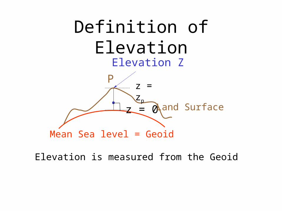
Definition of ElevationElevation Z
•
Pz = zp
z = 0
Mean Sea level = Geoid
Land Surface
Elevation is measured from the Geoid

Three systems for measuring elevationWhat reference system (datum) is used?
1. Orthometric heights (land surveys, geoid)2. Ellipsoidal heights (lidar, GPS)3. Tidal heights (Sea water level)
Earth surface
EllipsoidSea surface
Geoid
Geoid is mean sea level at a particular point and varies with gravitational potential

Three systems for measuring elevation
Orthometric heights(land surveys, geoid)
Ellipsoidal heights(lidar, GPS)
Tidal heights(Sea water level)
Conversion among these height systems has some uncertainty

Trends in Tide Levels(coastal flood risk is changing)
Charleston, SC
+ 1.08 ft/century
- 4.16 ft/century+ 2.13 ft/century
Juneau, AK
Galveston, TX
1900 2000
1900 2000
1900 2000

Gravity Anomaly
Ocean
Geoid
Earth surface
Ellipsoid
Gravity Anomaly
Gravity anomaly is the elevation difference betweena standard shape of the earth (ellipsoid) and a surfaceof constant gravitational potential (geoid)
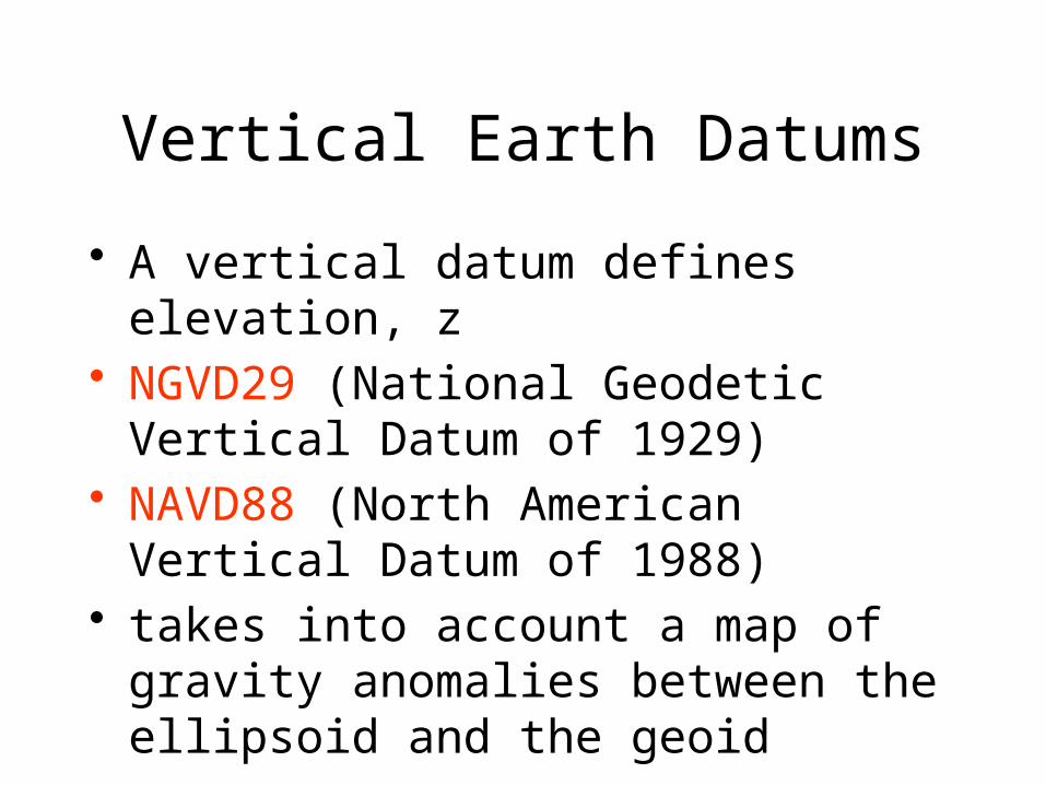
Vertical Earth Datums
• A vertical datum defines elevation, z• NGVD29 (National Geodetic Vertical
Datum of 1929)• NAVD88 (North American Vertical Datum
of 1988)• takes into account a map of gravity
anomalies between the ellipsoid and the geoid

Converting Vertical Datums• Corps program Corpscon (not in ArcInfo)
– http://crunch.tec.army.mil/software/corpscon/corpscon.html
Point file attributed with the elevation difference between NGVD 29 and NAVD 88
NGVD 29 terrain + adjustment= NAVD 88 terrain elevation

Importance of geodetic datumsNAVD88 – NGVD29 (cm)
NAVD88 higher in West
NGVD29 higher in East
Orthometric datum height shifts are significant relative to BFE accuracy, so standardization on NAVD88 is justified
More than 1 meter difference
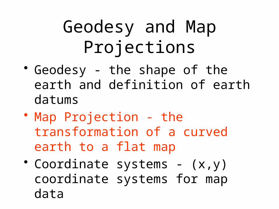
Geodesy and Map Projections
• Geodesy - the shape of the earth and definition of earth datums
• Map Projection - the transformation of a curved earth to a flat map
• Coordinate systems - (x,y) coordinate systems for map data

Earth to Globe to Map
Representative Fraction
Globe distanceEarth distance
=
Map Scale:Map Projection:
Scale Factor
Map distanceGlobe distance
=
(e.g. 1:24,000)(e.g. 0.9996)
To prepare a map, the earth is first reduced to a globe and then projected onto a flat surface

Geographic and Projected Coordinates
( , f l) (x, y)Map Projection
Map projection is how we go from the ‘true’ global (spheroid) system to a ‘flat’ X-Y system. There are many, many map projection systems.

How do we make Maps?-- Types of Projections --
• Conic (Albers Equal Area, Lambert Conformal Conic) - good for East-West land areas
• Cylindrical (Transverse Mercator) - good for North-South land areas
• Azimuthal (Lambert Azimuthal Equal Area) - good for global views
These projection techniques are how we create the ‘flat’ map from the globe

Projections Preserve Some Earth Properties (but not all at once)
• Area - correct earth surface area (Albers Equal Area) important for mass balances
• Shape - local angles are shown correctly (Lambert Conformal Conic)
• Direction - all directions are shown correctly relative to the center (Lambert Azimuthal Equal Area)
• Distance - preserved along particular lines• Some projections preserve two properties

Conic Projections(Albers Equal Area, Lambert Conformal Conic)
In the Secant method, a Cone is placed over the globe but cuts through the surface. The cone and globe meet along two latitude lines. These are the standard parallels. The cone is cut along the line of longitude that is opposite the central meridian and flattened into a plane.
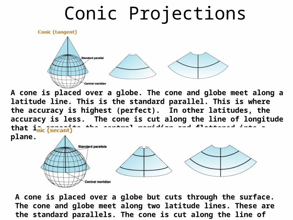
Conic Projections
A cone is placed over a globe. The cone and globe meet along a latitude line. This is the standard parallel. This is where the accuracy is highest (perfect). In other latitudes, the accuracy is less. The cone is cut along the line of longitude that is opposite the central meridian and flattened into a plane.
A cone is placed over a globe but cuts through the surface. The cone and globe meet along two latitude lines. These are the standard parallels. The cone is cut along the line of longitude that is opposite the central meridian and flattened into a plane.

Cylindrical Projections(Transverse Mercator)
Transverse
Oblique
Projecting the sphere onto a cylinder tangent
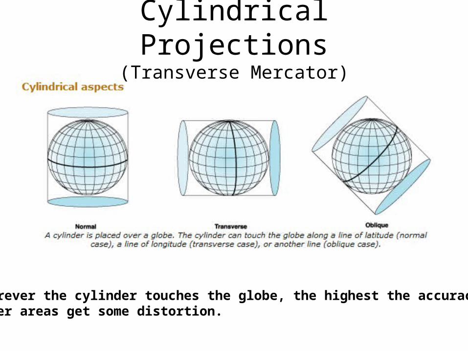
Cylindrical Projections(Transverse Mercator)
Wherever the cylinder touches the globe, the highest the accuracy. Other areas get some distortion.

Azimuthal (Lambert)
• A plane is placed over a globe. The plane can touch the globe at the pole (polar case), the equator (equatorial case), or another line (oblique case).
• All azimuthal projections preserve the azimuth (angle) from a reference point
• Presenting true direction (but not necessarily distance) to any other points.
• Also called planar since several of them are obtained straightforwardly by direct perspective projection to a plane surface.
Use this method if accuracy in ‘direction’ is more important than accuracy in ‘distance.’
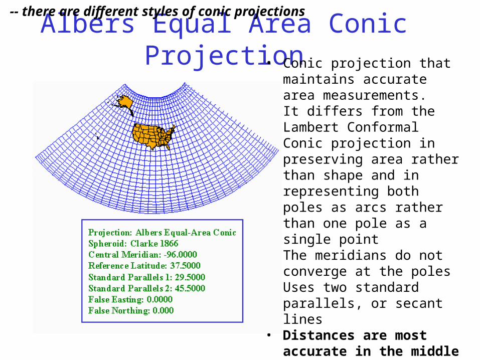
Albers Equal Area Conic Projection• Conic projection that
maintains accurate area measurements.
• It differs from the Lambert Conformal Conic projection in preserving area rather than shape and in representing both poles as arcs rather than one pole as a single point
• The meridians do not converge at the poles
• Uses two standard parallels, or secant lines
• Distances are most accurate in the middle latitudes.
-- there are different styles of conic projections

Lambert Conformal Conic Projection
• Portrays shape more accurately than area
• The State Plane Coordinate System uses this projection for all zones that have a greater east–west extent
• Represents the poles as a single point
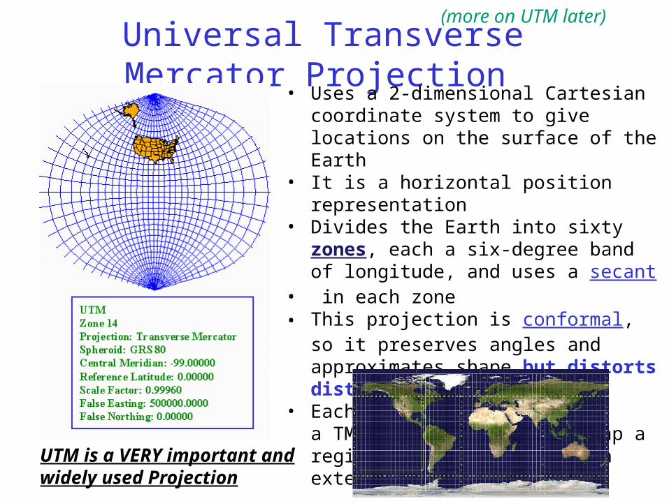
Universal Transverse Mercator Projection• Uses a 2-dimensional Cartesian coordinate
system to give locations on the surface of the Earth
• It is a horizontal position representation• Divides the Earth into sixty zones, each a six-
degree band of longitude, and uses a secant• in each zone• This projection is conformal, so it preserves
angles and approximates shape but distorts distance and area
• Each of the 60 zones uses a TM projection that can map a region of large north-south extent with low distortion
UTM is a VERY important and widely used Projection
(more on UTM later)
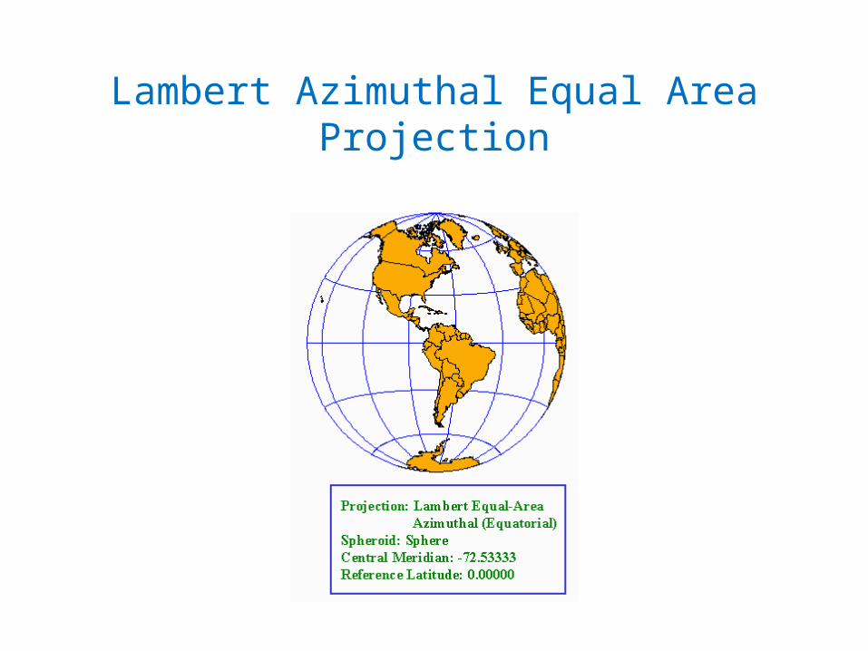
Lambert Azimuthal Equal Area Projection

Web Mercator Projection(used for ESRI Basemaps)
The spatial reference for the ArcGIS Online / Google Maps / Bing Maps tiling scheme is WGS 1984 Web Mercator (Auxiliary Sphere).
Web Mercator is one of the most popular coordinate systems used in web applications because it fits the entire globe into a square area that can be covered by 256 by 256 pixel tiles.
Web Mercator Projection is also used by Google Maps

Central Meridian
Standard Parallel (0,0)
(20037, 19971 km)Distance from origin = earth rad * π
6378 km
6357 km
Earth radius
Web Mercator Parameters

Projection and Datum
Two datasets can differ in both the projection and the datum, so it is important to know both for every dataset.

Geodesy and Map Projections
• Geodesy - the shape of the earth and definition of earth datums
• Map Projection - the transformation of a curved earth to a flat map
• Coordinate systems - (x,y) coordinate systems for map data
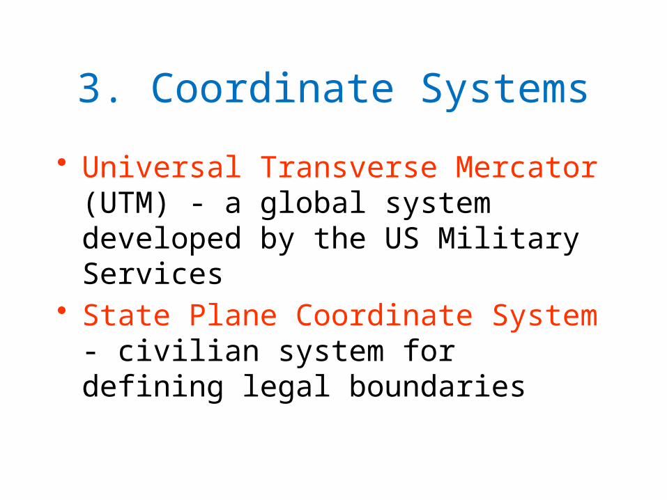
3. Coordinate Systems
• Universal Transverse Mercator (UTM) - a global system developed by the US Military Services
• State Plane Coordinate System - civilian system for defining legal boundaries

3. Coordinate System
(fo,lo)(xo,yo)
X
Y
Origin
A planar coordinate system is defined by a pairof orthogonal (x,y) axes drawn through an origin
The origin can be wherever the user wishes. However, there are standard locations.
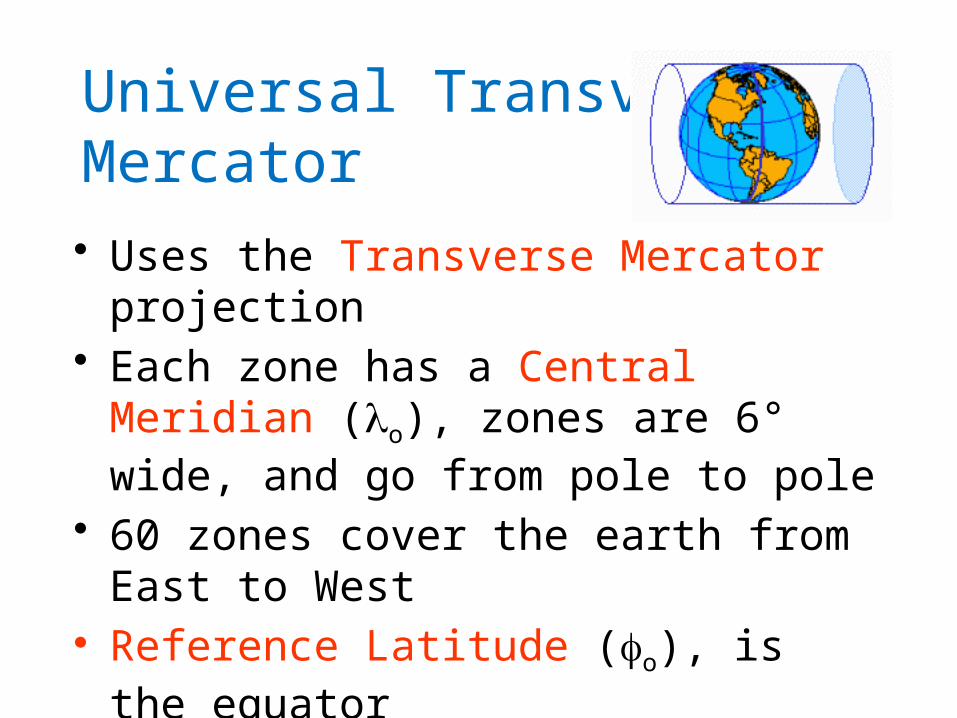
Universal Transverse Mercator
• Uses the Transverse Mercator projection• Each zone has a Central Meridian (lo), zones
are 6° wide, and go from pole to pole• 60 zones cover the earth from East to West• Reference Latitude (fo), is the equator
• (Xshift, Yshift) = (xo,yo) = (500000, 0) in the Northern Hemisphere, units are meters

UTM Zone 14
Equator-120° -90 ° -60 °
-102° -96°
-99°
Origin
6°
Zone 14 runs through Nebraska.

State Plane Coordinate System
• Defined for each State in the United States• East-West States (e.g. Texas) use Lambert
Conformal Conic, North-South States (e.g. California) use Transverse Mercator
• Nebraska has one zone, and Texas has five zones (North, North Central, Central, South Central, South) to give accurate representation
• Greatest accuracy for local measurements
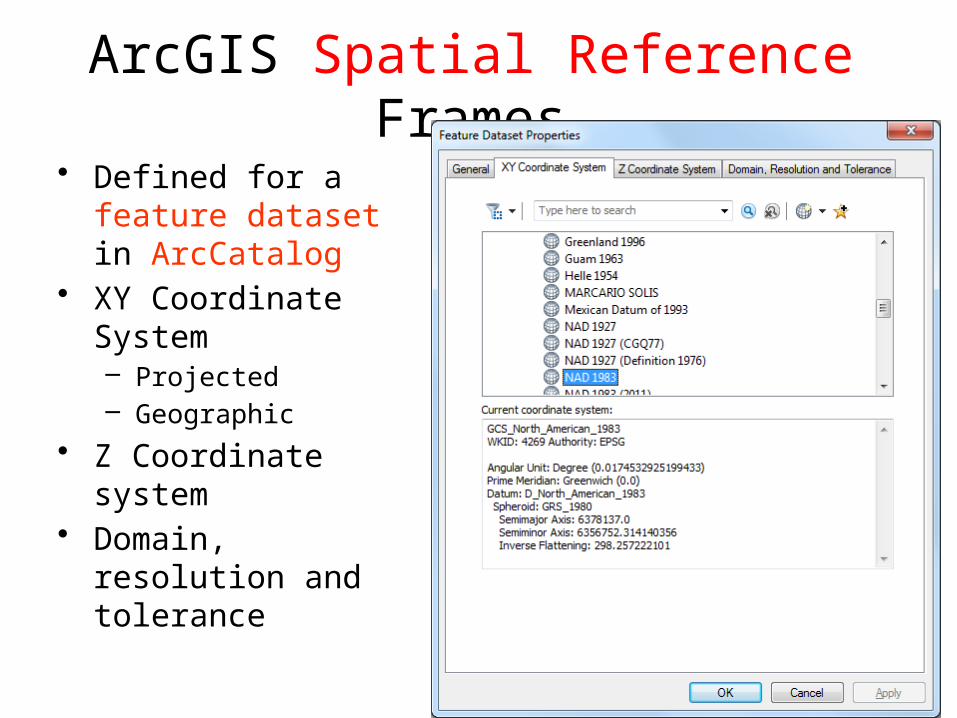
ArcGIS Spatial Reference Frames
• Defined for a feature dataset in ArcCatalog
• XY Coordinate System– Projected– Geographic
• Z Coordinate system• Domain, resolution and
tolerance

Horizontal Coordinate Systems
• Geographic coordinates (decimal degrees)• Projected coordinates (length units, ft or meters)
There are many, many coordinate systems available in Arc!

Vertical Coordinate Systems
• None for 2D data
• Necessary for 3D data

ArcGIS .prj files
The ‘prj’ file is used by Arc to hold information on the specific projection

Summary Concepts• The spatial reference of a dataset comprises
datum, projection and coordinate system.• For consistent analysis the spatial reference of
data sets should be the same.• ArcGIS does projection on the fly so can display
data with different spatial references properly if they are properly specified (but it is best to project layers to the same basis to check accuracy of overlapping).
• ArcGIS terminology– Define projection. Specify the projection for some
data without changing the data.– Project. Change the data from one projection to
another.

• Two basic locational systems: geometric or Cartesian (x, y, z) and geographic or gravitational ( , f l, z)
• Mean sea level surface or geoid is approximated by an ellipsoid to define an earth datum which gives ( , ) f l and distance above geoid gives (z)
Summary Concepts (Cont.)

Summary Concepts (Cont.)
• To prepare a map, the earth is first reduced to a globe and then projected onto a flat surface
• Three basic types of map projections: conic, cylindrical and azimuthal
• A particular projection is defined by a datum, a projection type and a set of projection parameters

Summary Concepts (Cont.)
• Standard coordinate systems use particular projections over zones of the earth’s surface
• Types of standard coordinate systems: UTM, State Plane
• Web Mercator coordinate system (WGS84 datum) is standard for ArcGIS basemaps

(Press and hold)
Trimble GeoXHTMGarmin GPSMAP 276C GPS Receiver
Global Positioning Systems
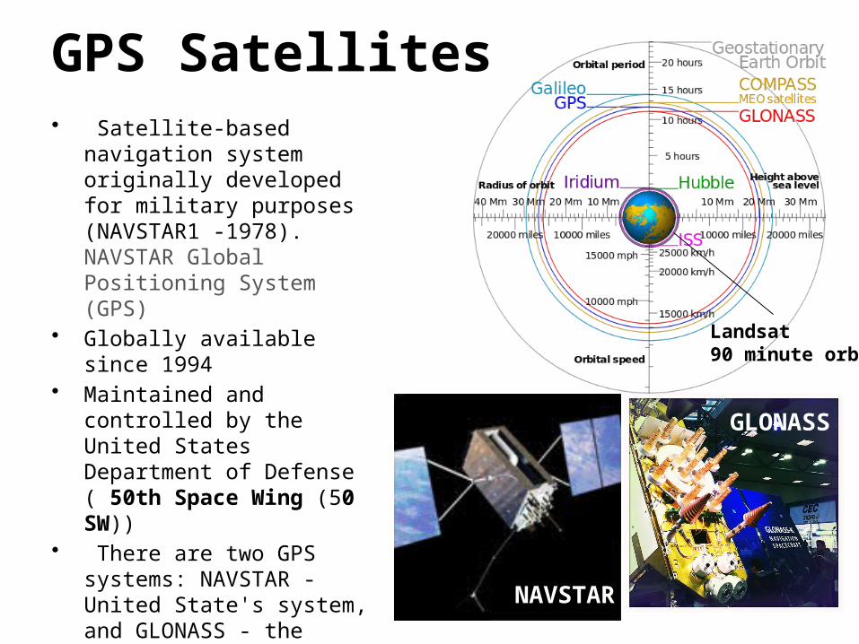
GPS Satellites• Satellite-based navigation system
originally developed for military purposes (NAVSTAR1 -1978). NAVSTAR Global Positioning System (GPS)
• Globally available since 1994• Maintained and controlled by the
United States Department of Defense ( 50th Space Wing (50 SW))
• There are two GPS systems: NAVSTAR - United State's system, and GLONASS - the Russian version
• GPS permits users to determine their three-dimensional position, velocity, and time.
NAVSTAR
GLONASS
Landsat90 minute orbit
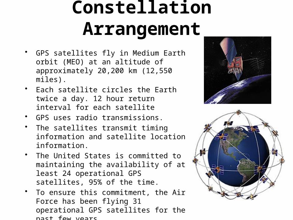
Constellation Arrangement
• GPS satellites fly in Medium Earth orbit (MEO) at an altitude of approximately 20,200 km (12,550 miles).
• Each satellite circles the Earth twice a day. 12 hour return interval for each satellite
• GPS uses radio transmissions. • The satellites transmit timing information and
satellite location information. • The United States is committed to maintaining the
availability of at least 24 operational GPS satellites, 95% of the time.
• To ensure this commitment, the Air Force has been flying 31 operational GPS satellites for the past few years.
• Satellites are distributed among six offset orbital planes
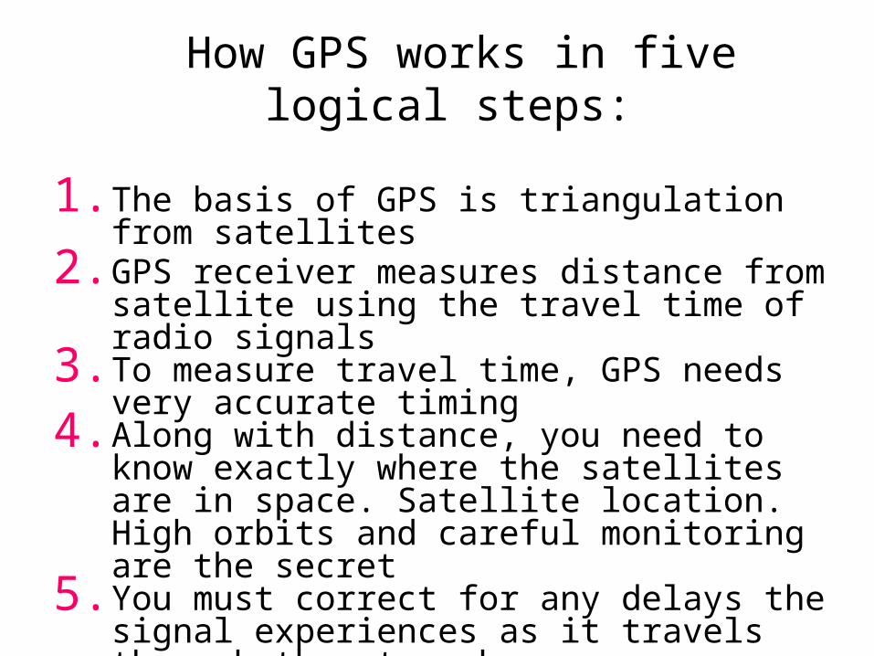
How GPS works in five logical steps:
1. The basis of GPS is triangulation from satellites2. GPS receiver measures distance from satellite using
the travel time of radio signals3. To measure travel time, GPS needs very accurate
timing 4. Along with distance, you need to know exactly
where the satellites are in space. Satellite location. High orbits and careful monitoring are the secret
5. You must correct for any delays the signal experiences as it travels through the atmosphere
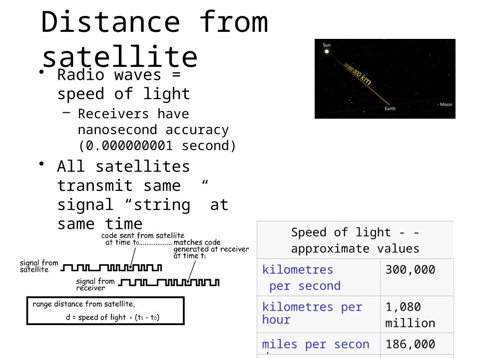
Distance from satellite• Radio waves = speed of
light– Receivers have nanosecond
accuracy (0.000000001 second)
• All satellites transmit same signal “string” at same time– Difference in time from
satellite to time received gives distance from satellite
Speed of light - -approximate values
kilometres per second 300,000
kilometres per hour 1,080 million
miles per second 186,000
miles per hour 671 million

Triangulation
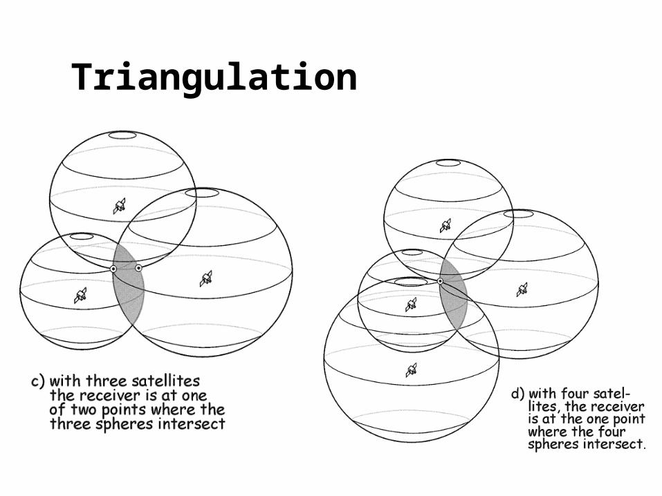
Triangulation

Differential GPS
• Differential GPS uses the time sequence of observed errors at fixed locations to adjust simultaneous measurements at mobile receivers
• A location measurement accurate to 1 cm horizontally and 2cm vertically is now possible in 3 minutes with a mobile receiver
• More accurate measurements if the instrument is left in place longer