
Geo Synthetics
30
Reinforced Soil Slopes 1 Soil Slope Design Guidelines 2 for Firm Foundations 5 Stability Analysis 9 Charts for Preliminary Design 14 Example Design Problem 19 Specification 24 Installation Guidelines 29 Geosynthetics for soil reinforcement REINFORCED SOIL ENGINEERING
description
soil reinforcement
Transcript of Geo Synthetics

Reinforced Soil Slopes 1
Soil Slope Design Guidelines 2
for Firm Foundations 5
Stability Analysis 9
Charts for Preliminary Design 14
Example Design Problem 19
Specification 24
Installation Guidelines 29
Geosynthetics forsoil reinforcement
R E I N F O R C E D S O I L E N G I N E E R I N G

reinforced soil slopes
Steepened slopes have become increasingly advantageous due
to the desire to increase land usage and decrease site develop-
ment costs. The proven concept of tensile reinforcement allows
construction of slopes with far steeper face angles than are per-
mitted by the soils natural angle of repose. Steepened slopes
reinforced with Mirafi® geosynthetics can increase land usage
substantially while providing a natural appearance.
The stability of a reinforced soil slope can be threatened by ero-
sion due to surface water runoff, or more severe forces associ-
ated with water currents and wave attack. Slope face erosion
may create rills and gullies, and result in surface sloughing and
possibly deep-seated failure (Berg.1993). Erosion control and
re-vegetation measures must, therefore, be an integral part of all
reinforced soil slope system designs. The type of erosion control
facing option selected depends on the finished slope face angle.
ADVANTAGES• Economics: significantly lowers site development costs by
providing soil retaining solutions without the costs of retainingwall facade materials
• Usability: drastically increases the amount of usable landwithin a given parcel without the cost of a traditional retainingwall
• Aesthetics: allows incorporation of ‘green’ surface
• Efficiency: speeds development and construction of site
• Reliability: proven design methodologies lead to successfulimplementation of steepened slopes.
APPLICATIONS
• Highway embankments
• Dikes and Levees
• Landslide repair
• Residential developments
• Commercial/ Office parks
• Landfills
steepened slope
unreinforced slope
firm foundation soil

Reinforced soil slopes with face angles less than 45 degreesare typically protected with soft armor systems. The functionof a soft armor system is to facilitate vegetation growth thatprovides long term erosion protection to the slope face. A
soft armor system consists of a temporary or permanent ero-sion blanket, a cellular confinement system, or other type oferosion control device along with natural vegetation. Twocommon soft armor facing options are shown below.
When slope face angles increase to greater than 45 degrees,a more durable facing system is required. Reinforced soilslopes with face angles greater than 45 degrees are typical-ly protected with hard armor systems. The function of a hardarmor system is to provide long term erosion protection tothe slope face. A hard armor system may also use vegeta-
tion as a means of erosion control. A hard armor systemconsists of a welded wire mesh or basket, stacked cellularconfinement panels, an open face SRW unit, or other type ofprotection device. These systems may also use natural veg-etation as a means of protection. Four common hard armorfacing options are shown below.
Cellular Confinement StabilizationRolled-Erosion Control Product (RECP)
Open Face SRW FacingWelded Wire Basket Facing
Gabion Basket FacingStacked Cellular Confinement Facing
Soft Armor (Slope Face Angle less than 45˚)
Hard Armor (Slope face angle greater than 45˚)
erosion protection options

Slopes are common geographic features located adjacent to highways and along the periphery of building sites in manyareas of the country. For construction on highway and building projects, relatively flat areas are preferred. These areas mustbe excavated out of the existing terrain, often leaving significant grade changes at the edges of the excavation. The eco-nomic feasibility of constructing a particular highway alignment or the development of a parcel of land may be determinedby the ability to create sufficient flat, or level, land to satisfy space safety, or access requirements. Reinforced steepenedslopes provide a cost-effective means to achieve more efficient grade changes than is possible with unreinforced slopes.Figure 1 illustrates some of the applications of reinforced steepened slopes.
REINFORCED STEEPENED SLOPE SYSTEM ON A FIRM FOUNDATION
Applications of a Reinforced Steepened Slope System
Figure 1: Applications Using Reinforced Steepened Slopes
Overview. Geosynthetic reinforced steepened slopes are soil structures constructed with slope face angles up to as high as70 degrees from horizontal. Typical unreinforced soil slopes are limited to slope face angles of approximately 25 to 30 degreesor less, depending on the slope soil. The additional steepness provided by reinforced slopes minimizes the extent to whichgrade change structures, i.e. slopes or walls, must encroach into highway right-of-way or onto building sites as shown in Fig2.
Details of a Reinforced Steepened Slope System
Figure 2: Conventional vs. Steepened Slopes

System Components. Like conventional soil slopes, reinforced slopes are constructed by compacting soil in layers whileshifting the face of the slope back to create the desired angle. Subsequently, the face is protected from erosion by vegeta-tion or other means. Additional geosynthetic elements maybe incorporated into reinforced steepened slopes to minimizeground water seepage and to enhance the stability of the steepened slope and the erosion resistance of the facing. The fol-lowing are the typical components of a geosynthetic reinforced steepened slope system:
• Foundation - Stable soil or bedrock upon which the slope is constructed. Stability in the foundation isassumed.
• Retained Soil - The soil which remains in place beyond the limits of the excavation.
• Subsurface Drainage - Geosynthetic drainage medium installed at the limits of the reinforced soil zone tocontrol, collect, and route ground water seepage.
• Reinforced Soil - The soil which is placed in lifts adjacent to the retained soil and incorporates horizontallayers of reinforcement to create the sloped structure.
• Primary Reinforcement- Geosynthetic, either geogrid or geotextile with sufficient strength and soil com-patible modulus, placed horizontally within the slope to provide tensile forces to resist instability.
• Secondary Reinforcement - Geosynthetic, either geogrid or geotextile that is used to locally stabilize theslope face during and after slope construction.
• Surface Protection - The erosion resistant covering of the finished slope surface.
Figure 3 shows typical components of areinforced steepened slope system andtheir relative locations. The primary rein-forcement provides a tensile strength com-ponent within the reinforced soil zone thatallows a slope to stand at steeper anglesthan would normally be achieved withoutreinforcement.
Figure 3: Typical Components of a Reinforced Steepened Slope System
Slope Geometry. The actual steepness requirements for a slope will result from the site layout and will be determined byassessing the topographic relationship between the toe line and the crest line. The grades, or steepness, of the slope aswell as slope height, will generally vary along the slope alignment requiring the designer to select reasonably spaced, repre-sentative cross-sections for reinforcement design. When selecting slope angle, β, and slope height, H, slope angles shouldbe no steeper than 70° and slope heights may be limited by surface water runoff considerations
Foundation Conditions. Slope stability analysis generally assumes that the foundation is firm, i.e. strong and stable, rela-tive to the slope fill soils and thus deep-seated failure modes are not typically a concern. Still, the designer must assess thefoundation conditions in the proximity of a proposed reinforced slope to assure that a failure plane passing through the foun-dation is unlikely. Soil test borings can be made to estimate subsoil strength and to locate geologic faults and ground waterelevations.
Site Specific Design Considerations

Ground Water. Ground water is a potential source of problems in soil structures. Unexpected ground water seepage canalter fill and foundation properties, cause internal erosion, "slicken" potential failure surfaces or increase horizontal and ver-tical loadings. All of these conditions can be minimized by identifying ground water sources, controlling seepage from them,and designing for the resulting expected soil moisture conditions. Whenever possible, ground water elevations should bemaintained well below the foundation level.
Fill. Reinforced slopes can be constructed from a wide variety of soils. This often allows on-site soils to be used, minimiz-ing the need to transport material on or off site. Preferred fill materials are predominately granular or low plasticity fine-grainedsoils. Fill soil properties should be obtained from laboratory testing of the candidate soils. Selecting soil properties for use indesign is discussed later.
Surcharge Loading. Additional vertical and horizontal loads are applied to the reinforced slope system by any surcharge orexternally applied loading, that is imposed upon the system. These loadings can result from structures, vehicles, or evenadditional soil masses. Applicable surcharge loadings must be resolved into corresponding horizontal and vertical forces onthe reinforced slope system. One way of doing this is to transform the surcharge load, q, into an equivalent additional soillayer equal to q/γ.
Other External Loading. Other externally applied loading such as point loads, seismic loads, or hydrostatic loads arebeyond the scope of this document, but must still be addressed by the designer if they are present.
Fill Soil and Geosynthetic Reinforcement Properties
Material Selection. Each prospective fill type will develop unique strength and reinforcement interaction properties underthe expected compaction and soil moisture conditions. Therefore, the cost-effectiveness of a reinforced slope can be affect-ed by the fill and corresponding reinforcement type selected. A thorough evaluation of potential fill and reinforcement mate-rials is necessary to identify the best possible combination.
Soil Properties. The critical equilibrium for steep reinforced slopes is usually governed by long term stability conditions. Thesoil strength is thus described in terms of its maximum unit weight, γmax, effective friction angle φ'f, and effective cohesion,c'(2). These properties are used to determine the stability of soil layers under design loadings. Table 1 outlines some typicalsoil types and ranges of associated soil properties. This information is for general groups of soils and should be used onlyas a guide. Specific soil properties for the foundation, fill and embankment soils on a given project should be determinedfrom field and laboratory testing.
Soil properties used in the design of reinforced slopes must reflect the expected in-situ conditions. Cohesion in the soil is oftenneglected which provides additional conservatism to the design. The controlled placement of the fill and the flexibility of the fin-ished structure generally assures a drained, large strain condition. The soil strength is properly described by either a largestrain or a factored peak effective soil friction angle, φ'f. The factored soil friction angle is calculated using Equation 1.
φ'f = tan-1 [(tanφ') /FS] (Eqn 1)
Table 1: Typical Soil Properties (1)
MDD** Std OptimumSoil Description USCS (Deg) Compact Moisture
Class* 0’ (lb/ft3) Content (%)Well-graded sand-gravel GW >38 125-135 11 - 8Poorly-graded sand-gravel GP >37 115-125 14 - 11Silty gravels, poorly graded sand-gravel-silt GM >34 120-135 12 - 8Clayey gravels, poorly graded sand-gravel-clay GC >31 115-130 14 - 9Well graded clean sand, gravelly sands SW 38 110-130 16 - 9Poorly-graded clean sands, gravelly sands SP 37 100-120 21 - 12Silty clays, sand-silts - clays SM 34 110-125 16 - 11Clayey sands, sand-clays SC 31 105-125 19 - 11Silts and clayey silts ML 32 95-120 24 - 12Clays of low plasticity CL 28 95-120 24 - 12Clayey silts, elastic silts MH 25 70-95 40 - 24Clays of high plasticity CH 19 75-105 36 - 19*Unified Soil Classification System**MDD=max dry density

Geosynthetic Reinforcement. The geosynthetic reinforcement, i.e. geogrids or geotextiles, used in slopes must satisfy bothstrength and soil interaction requirements. The strength requirements focus on the long term design strength (LTDS) of thereinforcement. Soil interaction properties include coefficients of direct sliding, Cds, and pullout, Ci.
Strength Properties. For reinforced soil structures it is important that the reinforcement be "compatible" with the soil. Thismeans that the long term design strength of the reinforcement should be acheived at a total strain level (elastic + creep) cor-responding to a strain in the soil matching peak soil strength. For most soils the strain level at peak soil strength is between3% and 10% and is easily determined by laboratory testing. As a result, a total strain level not to exceed 10% is common-ly used for steepened slopes, though a limiting strain of 5% may be appropriate if sensitive structures are adjacent to theslope.
The long term design strength (LTDS) of a reinforcement is determined by applying partial factors of safety to the ultimatetensile strength. These partial factors of safety account for creep, chemical and biological durability and installation dam-age. Equation 2 is used to calculate LTDS. Table 2 provides LTDS values in the primary machine strength direction (MD) forselected Mirafi® reinforcement products.
LTDS = Tult / [RFcr x RFid x RFd] (Eqn 2)
where: Tult = ultimate wide width tensile strength RFcr = reduction factor for creep deformationRFd = reduction factor for durability RFid = reduction factor for installation damage
LTDS (In sand)Geosynthetic (lb/ft)Miragrid® 2XT 949Miragrid® 3XT 1558Miragrid® 5XT 2234Miragrid® 7XT 2961Miragrid® 8XT 3636Miragrid® 10XT 4312
Table 2- LTDS for Selected Geosynthetics
Soil Interaction Properties. The coefficient of direct sliding, Cds, and the pullout interaction coefficient, Ci , are both meas-ures of the interaction between the geosynthetic and the soil and are determined by laboratory testing. The value Cds is usedin the calculation of factors of safety involving a block of soil sliding over a geosynthetic layer. Ci is used to determine thelength of geosynthetic which must extend beyond the critical failure surface to fully develop, or anchor, the reinforcement.Equation 3 is used to calculate this ‘embedment’ length, L. Table 3 provides Cds, and Ci values for selected Mirafi® geosyn-thetics in typical soils (4,5,6).
Tpull = 2 x Ci x L x o’v x tanφ'f (Eqn 3)
Table 3- Coefficient of Shear Stress Interaction for Mirafi® Construction Products
Coefficient of Shear Stress Interaction Ci Coefficient of Direct Sliding Cds
Miragrid®
Soil Type Geogrids Sands 0.9-1.0 0.9Silts 0.8-0.9 0.8Clays 0.7-0.8 0.7Note: These values are for preliminary design purposes only. Specific test results are available from the Mirafi® Technical Services Department, upon request.

STABILITY ANALYSIS FOR STEEPENED SLOPES AND EMBANKMENTS OVER STABLE FOUNDATIONS
The two-part wedge analysis method for a soil slope or embankment over a stable foundation can be referenced to Figure4. A trial failure mechanism is defined by potential linear failure surfaces that are assumed to propagate from a point on theslope (point A) to a breakpoint (B) and then exit at the slope surface at point (C) located at or beyond the slope crest. Thepotential failure zone therefore comprises two soil masses (wedges) identified as regions 1 and 2 in the figure. If a reinforce-ment layer intersects a potential failure surface then it provides a horizontal restraining force that is included in the overallcalculation of horizontal force equilibrium.
In a typical analysis a large number of two-part wedge geometries must be inspected in order that the critical geometry isfound (i.e. the two-part wedge giving the lowest factor-of-safety against slope failure). It is clear that the only practical methodof identifying the critical failure mechanism is to use a computer program. Computer programs RSS, available from FederalHighway Administration by ADAMA (FHWA NH1-00-043) engineering can be used to carry out two and three part wedgeanalysis for slopes with varying geometrics, soil properties, and groundwater elevations. Other commercial software pro-grams are also available.
Two-part Wedge Analysis
Figure 4: Two-part wedge analysis
The stability calculations for an assumed two-part wedge failure mechanism can be referenced to Figure 4.
For illustration purposes, the procedures described in the section are restricted to reinforced slopes with uniform, cohe-sionless soils (i.e., c'= 0, φ'>0) and the groundwater table well below the toe elevation.
The destabilizing forces acting on the slope include the bulk weight of the trial wedges W1 and W2 and any uniformly dis-tributed surcharge q. The resisting forces include the shear resistance developed along the bottom and top failure planes,S1 and S2 and the horizontal tensile forces developed by the intersected reinforcement layers. The shearing resistance alongthe failure planes AB and BC are assumed to be Coulomb type with S1 = N1 x tanφ’f and S2 = N2 x tanφ’f. The soil frictionangle used in the computation is the factored soil friction angle (φ’f) calculated according to Equation 1.
The quantity P2 in Figure 4 is the unbalanced force that is required to keep the upper wedge at limit equilibrium. In general,the orientation of the interslice friction angle will be 0 < λ < φ’f. A conservative assumption is λ = 0 (i.e., results in a saferdesign).
The factor-of-safety (FS) against failure of a trial two-part wedge is the minimum value that can be applied to the peak soilfriction coefficient so that the horizontal destabilizing force P Is just equal to the sum of the factored horizontal tensile capac-ities of the reinforcement layers ST/FS. The sum ΣT is calculated from the tensile capabilities of the reinforcement layers thatare intersected by the trial failure surfaces (i.e., T2 through T6 in Figure 4).
Stability Calculations
q

The out-of-balance horizontal force P is calculated using Equation 4a, 4b and 4c. The wedge weights W1 and W2 includethe net vertical force due to any uniformly distributed surcharge load acting over the slope surface.
The maximum tensile force Ti available from any individual reinforcement layer is the lesser of the long term design strength(LTDS) or the design pullout capacity of the geosynthetic, Tpull.
P = P2cos λ+ (P2sinλ + W2) { sinθ2 - cosθ2tanφ’f } (Eqn 4a)cosθ2 + sinθ2tanφ’f
where, P2cosλ = W1 { tanθ1 - tanφ’f } (Eqn 4b)1+ tanθ1 tanφ’f
and φ’f = tan-1{ tanφ’f } (Eqn 4c & Eqn 1)FS
A summary of possible failure mechanisms that must be examined to find the critical mechanism is illustrated in Figure 5.Other permutations include external base sliding in which no reinforcement layers are intersected by the upper wedge.
Figure 5: Some Two-Part Wedge Failure Mechanisms
Figure 5b illustrates an internal direct sliding mechanism in which the bottom wedge boundary coincides with a layer of rein-forcement. Conventional practice is to assume that the potential shear resistance along this bottom surface is modified bythe presence of the reinforcement layer. For this condition the friction coefficient term (tanφ’f) in the denominator and numer-ator of Equation 4a becomes (α x tanφ’f) where α is the direct sliding coefficient. The magnitude of the direct sliding coeffi-cient is restricted to α < φ’f. For Miragrid® geogrid products in combination with well-compacted granular soils, Mirafi®
Construction Products recommends a value of α =0.9 for preliminary design purposes. For final design and analysis pur-poses a representative value of the direct sliding coefficient can be determined from the results of direct shear box testing.These tests should use the proposed geosynthetic reinforcement material and slope soils prepared to the same conditionsas in the field.
Internal Sliding

A minimum factor-of-safety for reinforced slopes with frictional soils is FS=1.5 applied to Eqn 1. The actual choice of factor-of-safety should be based on the recommendation of a geotechnical engineer who is familiar with the soils at the site, slopefunction, additional loads, proposed reinforcement material and method of construction.
Circular Slip Analysis
This section reviews circular slip methods of analysis for the design and analysis of steepened slopes and embankmentsover stable foundations. For design purposes, the slopes are assumed to be seated on competent foundation soils or rockthat are incompressible. Potential failure surfaces are assumed to be restricted to the slope soils or embankment fill abovethe stable foundation.
The method of analysis described in the manual is based on a modified "Bishop's Simplified Solution" in which the factor-of-safety against slope failure is described by the ratio of the sum of resisting moments to the sum of driving moments cal-culated using the method of slices. The driving moments are due to soil self weight and any surface loadings. The resistingmoments are proportional to the mobilized soil shearing resistance developed along the failure surface. This conventionaland widely used method of analysis can be easily modified to include the resisting moment due to any reinforcement layerthat intersects a trial failure surface. The methodology described in this section follows the recommendations contained inthe FHWA guidelines(3) for reinforced slopes.
In the examples to follow the soils are assumed to be granular materials and stability calculations are based on an effectivestress analysis. The analysis are therefore appropriate for drained soils.
Unreinforced Slope
The factor-of-safety FSu for an unreinforced slope is expressed as:
FSu = Resisting Moment = Mr (Eqn 5) Driving Moment Md
The slope can be divided into a convenient number of slices as illustrated in Figure 6 for a prescribed center-of-rotation 0and Radius R. The factor-of-safety Equation 5 can be expanded as shown in Equation 6. Here the summation signs are withrespect to the vertical slices.
The parameters shown in Figure 6 and in Equation 6 are:
W = total weight of slice based on bulk unit weight of soil plus surcharge loading (q x b) if present q = uniformly distributed surcharge acting at crest of slope b = the horizontal width of the sliceψ = the angle formed by the tangent to the midpoint of the slice and the horizontalc’ = soil cohesion at base of slice φ’ = peak soil friction angle at base of sliceru = dimensionless pore water pressure coefficient
FSu = 1 Σ [{c'b + W(1 - ru)tanφ’} secψ ] (Eqn 6)ΣWsinψ 1 + tanψtanφ'
FSu
The porewater pressure coefficient ru can be approximated using the approach illustrated in Figure 6. The result may be asmall error that is conservative. For any slice that does not intersect the groundwater table ru = 0.
Factor-of-Safety

The presence of the factor-of-safety term on both sides of Equation 6 means that for a prescribed trial failure circle, a processof successive iterations is required until the solution converges to a unique value of FSu. Clearly, the computations requiredto perform this calculation and to inspect a potentially large number of critical slip circles means that the analysis is best per-formed using a computer program.
Commercially available computer programs such as G Slope from Mitre Software Corporation, RSS from FHWA, ReSSA andReSlope from ADAMA Engineering, STABL from Purdue Universiy, and UTEXAS4 from the University of Texas, as well asothers, can be used fro this purpose.
Reinforced Slope
The factor-of-safety FSr for a reinforced slope is expressed as:
FSr = FSu + resisting movement due to reinforcement (Eqn 7) driving moment
The right hand term represents the additional factor-of-safety against slope failure due to the stabilizing effect of the tensilegeosynthetic reinforcement. Referring to Figure 7, the factor-of-safety expression for the reinforced slope case can beexpressed as:
FSr = FSu + (ΣTiRTi/cosψ1) (Eqn 8)
MD
Figure 6: Circular Slip Analysis and Method of Slices for Unreinforced Slope

Here the summation term is with respect to the reinforcement layers and the tangent slopes ψi of the circular slip surface atthe point of intersection with each reinforcement layer i. Some engineers argue that the restoring force Ti will act parallel tothe slip surface if the reinforcement products are extensible materials (e.g. Miragrid®). Extensible reinforcement products areable to conform to the geometry of the failure surface at incipient collapse of the slope.
The magnitude of the tensile force Ti used for each layer in the summation term in Equation 8 is the lesser of:
1. The long term design strength of the reinforcement (LTDS). This is the working tensile load level below which the rein-forcement remains intact and does not undergo excessive straining.
2. The pullout capacity of the embedded length of the reinforcement beyond the slip circle (i.e. length Ia in Figure 7). Thequantity Ti must not exceed the pullout capacity (Tpull) of the reinforcement. The calculation of pullout capacity is performedby using equation 3.
The above method can be used with commercially available software for circular slip analysis of unreinforced slopes providedthat the magnitude of the driving moment MD is available in the output. The magnitude of the right hand term in Equation 8
Figure 8: Approximate Method to Calculate the Factor-of-Safety for a Reinforced Slope(3)
Figure 7: Circular Slip Analysis and Method of Slices for Reinforced Slope

can then be computed by hand or by using a simple computer spreadsheet. Alternatively, the approximate methoddescribed in the following section can be used to give a reasonably conservative estimate of the reinforced slope factor-of-safety.
Approximate Method to Calculate Factor-of-Safety for Trial Reinforced Slope
For preliminary design purposes the factor-of-safety from the results of an unreinforced slope stability analysis can be mod-ified to estimate the factor-of-safety for the corresponding reinforced slope using extensible reinforcement (refer to Figure 8):
Step 1. Calculate FSu for the unreinforced slope and determine the geometry of the corresponding critical slip circle.
Step 2. Calculate the total available restoring force ΣTi based on the sum of the LTDS of all reinforcement layers that inter-sect the critical slip circle from Step 1.
Step 3. Assume that ΣTi acts parallel to the critical unreinforced slip circle and calculate the factor-of-safety for the reinforcedslope as follows:
FSr = FSu + R x ΣTi (Eqn 9)MD
External Stability of a Reinforced Soil Mass over a Stable Foundation(3)
The FHWA guidelines contain recommendations for the analysis of external sliding stability of a reinforced soil mass over astable foundation. The sliding mechanism assumed in these calculations is conceptually identical to the sliding mechanismillustrated in Figure 5d. The reinforced soil mass is treated as an equivalent gravity structure with a mass equal to the rein-forced zone above the base. The factor-of-safety against base sliding is calculated as the ratio of base sliding resistance(force/unit width of slope) to driving force resulting from the retained slope materials.
The limits of the reinforced soil mass can be estimated using the Design Chart Method described in the next section or theresults of circular sup analysis described in the previous section.
CHARTS FOR PRELIMINARY DESIGN OF STEEPENED SLOPESAND EMBANKMENTS OVER STABLE FOUNDATIONS
This section describes how the designer can use a series of charts to carry out a preliminary design of a reinforced soil slopeor embankment. The preliminary designs that result from this approach are restricted to slopes or embankments composedof free-draining granular soils and constructed over stable foundations. The charts have been generated using a conven-tional two-part wedge limit equilibrium method of analysis and cover the case of simple geometry with a range of slopesfrom 90 degrees (vertical) to 30 degrees and a range of soils with friction angles from 15 degrees to 50 degrees. A factoredsoil friction angle φ’f (Equation 1) should be used with the design charts to account for variability in soil properties and uncer-tainty in slope geometry and loading.
Principal Assumptions
The basic assumptions used to generate the charts are as follows:
1. The foundation soils below the toe of the slope are stable and any potential instability is restricted to the free-draining
cohesionless granular soil mass above the elevation of the toe.
2. The groundwater table is well below the toe of the slope.
3. The properties of the soil are uniquely described by a uniform bulk unit weight λ and a peak friction angle φ’ (degrees).
4. The intersection of failure surfaces with the slope boundaries occurs at the toe of the slope and at points beyond the
crest.
5. lnterslice forces have been assumed to act at an angle of λ = φ’ to the horizontal.
6. No additional slope loadings due to seismic forces are present.
7. The primary reinforcement utilized is a Mirafi® reinforcement product.

Calculation of Factored Soil Friction Angle for Design
A factor-of-safety FS should be applied to the soil peak friction angle to account for variability in soil properties and uncer-tainty in slope geometry and loading. For routine slopes a value of FS = 1.5 is typical. However, it is the responsibility of thegeotechnical engineer to recommend an appropriate factor-of-safety based on site conditions, external loading and slopefunction. The factored soil friction angle φ’f is used in the calculations described in the following text. The factored soil fric-tion angle is calculated as follows:
φ’f = tan-1{(tanφ’) /FS} (Eqn 10)
Design ChartsCoefficient of Earth Pressure (Chart 1)In order to estimate the minimum number of primary reinforcement layers in a slope it is necessary to calculate the net hori-zontal force P required to just maintain the slope at limit equilibrium. The approach adopted to generate the design charts is todetermine the critical two-part wedge that yields the maximum required horizontal force P. The geometry used in the two-partwedge analysis is illustrated in Figure 9.
Chart 1 gives the maximum equivalent coefficient of active earth pressure K based on a search of all potential two-partwedges for a given β and factored friction angle (i.e φ’ =φ’f). The magnitude of force P is determined by examining a very largenumber of wedge geometries defined by a grid of break-points superimposed on the slope cross-section. For each break-point the angle θ2 was varied to determine the maximum out-of balance force P. The analysis assumed that interslice forcesact at 1/3 the height of the interslice boundary (the point of application is a concern in eccentricity calculations described in thenext section).
Chart 1: Equivalent Coefficient of Earth Pressure, K= f(φ’f, β)

The constraint that the width L of the reinforced zone must be sufficient to capture the critical two-part wedge is illustrated inFigure 10. The calculation for adequate reinforcement zone width to prevent base sliding can be referred to Figure 11. The cal-culations to determine the minimum base width to prevent sliding were based on the following factor-of-safety relationship:
FS = S (Eqn 11)P2cosλ
= α (W1 = P2sinλ ) tanφ’ = 1P2cosλ
Figure 9:Two-Part Wedge Anaylysis toCalculate Unbalanced HorizontalForce P.
Figure 10:Reinforced Zone ContainingCritical Two-Part Wedge
Figure 11:Free Body Diagram for Calculationof Base Sliding
Minimum Reinforcement Length (Chart 2)
The calculation of the minimum length of reinforcement was based on the following criteria:
1. All reinforcement lengths are equal (i.e. truncation parallel to the slope face).2. The reinforced zone must have sufficient length L to contain the critical unreinforced two-part wedge.3. The reinforced zone must have sufficient length L that the slope does not slide outward.4. The reinforced zone must have sufficient length L that tensile vertical stresses are not developed along the surface of the
foundation soils (i.e., base eccentricity must fall within the middle third of the base width L).

Here the parameter S is the shearing resistance acting at the base of the slope and is controlled by the friction angle of theslope soils φ’, the weight of wedge W1 (hence width of the reinforced zone L) and the coefficient of direct sliding (which hasbeen taken as α = 0.9). The quantity P2 is the unbalanced interslice force acting on wedge 1 by the right hand side wedge2.
The calculation for base eccentricity can be referenced to Figure 12. The analysis involves progressively increasing the basedimension L until the linear distribution of vertical base pressure σ’v, is compressive everywhere for maximum values of P2.
The results of analysis are presented in normalized form L/H on Chart 2 for the condition λ = φ’ (where φ’ = φ’f). Here, L isthe length of reinforcement and H is the height of the slope.
Calculation of Minimum Number of Reinforcement Layers
The equivalent coefficient of earth pressure K for design is determined from Chart 1 using φ’f. The minimum number of rein-forcement layers Nmin can be calculated as follows:
Nmin >= P = (1/2) KγH2 (Eqn 12)LTDS LTDS
Here term LTDS denotes the long term design strength (allowable working stress) of the Mirafi® reinforcement products.
Chart 2: Minimum Ration of Reinforcement Length to Slope Height L/H to containCritical Two-Part Wedge and Satisfy Sliding and Eccentricity Criteria.

Calculation of Minimum Length of ReinforcementThe minimum reinforcement length L is calculated from Chart 2 based on φ’f, β, and the height of the slope H.
Calculation of Maximum (Primary) Reinforcement Spacing
The calculation of maximum reinforcement spacing Svmax at any depth z below the crest of the slope can be carried out usingthe following relationship:
Svmax = > LTDS (Eqn 13)Kγz
Here the quantity LTDS refers to the long term design strength of the reinforcement and parameter K to the coefficient ofearth pressure established from Chart 1. The value of Svmax in Equation 23 is dependent on the magnitude of bulk moist unitweight of the soil γ, the value K and the LTDS of the reinforcement. Hence, it is not practical to provide a general chart toestimate Svmax. A spacing design chart based on the example problem at the end of this chapter illustrates the procedure.
Figure 12Free body diagram associatedwith calculation of minimumreinforcement length L to ensurecompressive bearing pressuresat base of slope (i.e., baseeccentricity <L/6)
Uniform Surcharge
The influence of a uniformly distributed surcharge q acting at the crest of the slope (Figure 13) can be considered by ana-lyzing a slope with an equivalent unsurcharged height H' where:
H' = H + q/γ (Eqn 14)
The replacement of the surcharged slope height by an equivalent unsurcharged height H' is valid for q/γ < O.2H. For greatersurcharge pressures a more detailed slope stability analysis should be carried out.
Figure 13: Modified Slope Height to Incline Influence of Uniformly Distributed Surcharge

Example Design Problem
The following design example is related to the proposed slope geometry and site parameters shown inExample Figure 1. The engineer is required to recommend a reinforcement layout using Miragrid® geogrid rein-forcement products.
Example Figure 1:Proposed slope geometry and soilparameters for design example.
Step 1
Select design parameters for soil and Miragrid properties
Embankment soil properties:
Peak friction angle, φ’ = 30o Slope height, H = 30 ft Cohesion. c' = 0 psf Uniform surcharge pressure, q = 250 psf bulk unit weight, γ = 125 pcf Slope angle, β = 45o
Slope factor-of-safety, FS = 1.5
Geogrid properties: Long term design strength (LTDS), in Type 3 backfill: sand, silt, clay:Miragrid 2XT = 949 lb/ftMiragrid 3XT = 1558 lb/ftMiragrid 5XT = 2234 lb/ftMiragrid 7XT = 2961 lb/ftMiragrid 8XT = 3636 lb/ftMiragrid 10XT = 4312 lb/ft
Step 2
Calculate factored friction angle φ’f:φ’f = tan-1 { (tanφ’)/ FS}φ’f = tan-1 {(tan30o)/1.5} = 21.0o

Step 3
Calculate equivalent slope height H:
H’ = H + (q/γ)H’ = 30 + (250/125) = 32 ft
Step 4
Determine the force coefficient K, from Chart 1 using the slope angle β, and the factored friction angle φ’f:
K = 0.18
Step 5
Determine the total horizontal force P that must be resisted by the Miragrid® reinforcement layers:
P = (1/2) Kγ (H’)2
P = (1/2) 0.18 (125)(32)2 = 11520 lb/ft
Step 6
Calculate minimum number of Miragrid® layers Nmin required to counter unbalanced force P:
Nmin = P/(LTDS)Nmin = for Miragrid 2XT = 11520/949 = 12.1 layers - 13 layersNmin = for Miragrid 3XT = 11520/1558 = 7.4 layers - use 8 layersNmin = for Miragrid 5XT = 11520/2234 = 5.2 layers - use 6 layersNmin = for Miragrid 7XT = 11520/2961 = 3.89 layers - use 4 layersNmin = for Miragrid 8XT = 11520/3636 = 3.2 layers - use 4 layers
Step 7
Determine the required embedment length of primary geogrid from Chart 2 using factored friction angleφ’f,slope angle β and modified slope height H’:
L/H’ ratio from Chart 2 = 1.0L = (L/H’) (H’)L = (1.0) (32) = 32.0 ft
Step 8
Calculate the maximum allowable vertical spacing for each Miragrid product using:
Svmax = (LTDS) / (Kγz)

Where z is the distance from the top of the slope with height H'. It may be convenient to develop a chart suchas that shown in Example Figure 2. Select spacing of geogrid layers starting from the bottorn of the slope andworking up. For example: the spacing chart illustrates that Miragrid® 7XT, 8XT, and 10XT would not be rec-ommended since at any elevation in the slope they are too strong and the spacing would be controlled by the4 foot maximum spacing criterion recommended in the FHWA guidelines. A more reasonable selection wouldbe Miragrid® 2XT, 3XT, 5XT or a combination of these products.
Miragrid 8XTLTDS = 3636 lbs/ft
Miragrid 7XTLTDS = 2961 lbs/ft
Miragrid 5XTLTDS = 2234 lbs/ft
Miragrid 3XTLTDS = 1558 lbs/ft
Miragrid 2XTLTDS = 949 lbs/ft
Svmax = LTDSK γ z
Example Figure 2: Example Design ProblemCalculation of maximum spacing for primary reinforcement
(K - 0.18, γ = 125 lbs/ft3 and H’ = 32 ft)
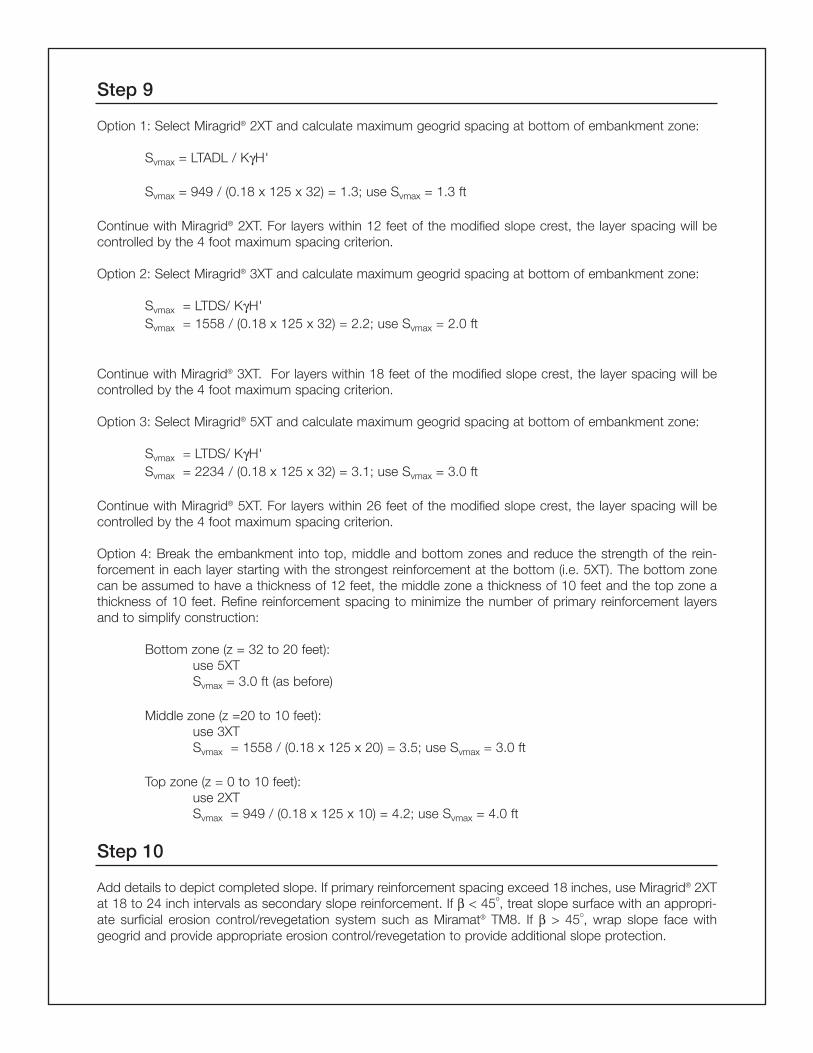
Step 9
Option 1: Select Miragrid® 2XT and calculate maximum geogrid spacing at bottom of embankment zone:
Svmax = LTADL / KγH'
Svmax = 949 / (0.18 x 125 x 32) = 1.3; use Svmax = 1.3 ft
Continue with Miragrid® 2XT. For layers within 12 feet of the modified slope crest, the layer spacing will becontrolled by the 4 foot maximum spacing criterion.
Option 2: Select Miragrid® 3XT and calculate maximum geogrid spacing at bottom of embankment zone:
Svmax = LTDS/ KγH'Svmax = 1558 / (0.18 x 125 x 32) = 2.2; use Svmax = 2.0 ft
Continue with Miragrid® 3XT. For layers within 18 feet of the modified slope crest, the layer spacing will becontrolled by the 4 foot maximum spacing criterion.
Option 3: Select Miragrid® 5XT and calculate maximum geogrid spacing at bottom of embankment zone:
Svmax = LTDS/ KγH'Svmax = 2234 / (0.18 x 125 x 32) = 3.1; use Svmax = 3.0 ft
Continue with Miragrid® 5XT. For layers within 26 feet of the modified slope crest, the layer spacing will becontrolled by the 4 foot maximum spacing criterion.
Option 4: Break the embankment into top, middle and bottom zones and reduce the strength of the rein-forcement in each layer starting with the strongest reinforcement at the bottom (i.e. 5XT). The bottom zonecan be assumed to have a thickness of 12 feet, the middle zone a thickness of 10 feet and the top zone athickness of 10 feet. Refine reinforcement spacing to minimize the number of primary reinforcement layersand to simplify construction:
Bottom zone (z = 32 to 20 feet):use 5XTSvmax = 3.0 ft (as before)
Middle zone (z =20 to 10 feet):use 3XTSvmax = 1558 / (0.18 x 125 x 20) = 3.5; use Svmax = 3.0 ft
Top zone (z = 0 to 10 feet):use 2XTSvmax = 949 / (0.18 x 125 x 10) = 4.2; use Svmax = 4.0 ft
Step 10
Add details to depict completed slope. If primary reinforcement spacing exceed 18 inches, use Miragrid® 2XTat 18 to 24 inch intervals as secondary slope reinforcement. If β < 45o, treat slope surface with an appropri-ate surficial erosion control/revegetation system such as Miramat® TM8. If β > 45o, wrap slope face withgeogrid and provide appropriate erosion control/revegetation to provide additional slope protection.

Step 11
Sketch slope showing primary and secondary reinforcement as noted on Example Figure 3. The final recom-mended design will be based on a layout that is a compromise between the requirement layers and the desireto keep the layout as simple as possible to ease construction.
Step 12
Verify the internal stability and calculate the external stability of the cross section using slope stability meth-ods. Since the computations required to perform the required number of calculations would be prohibitive toperform by hand, the analyses are best performed by computer program. Failure modes including, by notlimited to, multiple wedge type internal faiure modes, sliding block or translational and circular arc rotationalexternal failure modes should be considered. Site-specific conditions will often control the reinforcementscheme chosen for the final reinforced slope cross sections.
References
1.Carter, M. and S.P. Bentley (1991). Correlations of Soil Properties. Pentech Press, London. pp. 46, 90-91.2.Jewell, R.A. (1991). Revised Design Charts for Steep Reinforced Slopes. Reinforced Embankments: Theory
and Practice. D.A. Shercliff, Editor, Thomas Telford LTD., London. pp. 1-30.3.Geotextile Design and Construction Guidelines (1989a). NHI Course No. 13213, Pub. No. FHWA-HI-95-039,
Revised April 1998.4.Mirafi Miragrid Reinforced Soil Submittal Binder, TC Mirafi. 1998.5.Geosyntec Consultants. Final Report Geosynthetic Pullout Testing - Select Miragrid XT Geogrids with Con-
crete Sand, April, 2001.6.Koutsourais, M., Sandri, D., and Swan, R. Soil Interation Characteristics of Geotextiles and Geogrids. Con-
ference Proceedings from the Sixth International conference of Geosynthetics, vol 2, pp. 739-744.
Example Figure 3: Example Miragrid® Reinforcement Layout

Specification for Geosynthetic Used as Soil Reinforcement in Mechanically Stabilized Earth Retaining Structures
1 GENERAL
1.1 SECTION INCLUDESA. Geosynthetic to provide reinforcement for mechanically stabilized earth retaining structures. The primary functionof the geosynthetic is reinforcement.
1.2 RELATED SECTIONSA. Section 02050 - Basic Site Materials and MethodsB. Section 02100 - Site RemediationC. Section 02200 - Site PreparationD. Section 02300 - EarthworkE. Section 02830 - Retaining Walls
1.3 UNIT PRICESA. Method of Measurement: By the square meter (or square yard - as indicated in contract documents) includingseams, overlaps, and wastage.B. Basis of Payment: By the square meter (or square yard - as indicated in contract documents) installed.
1.4 REFERENCESA. AASHTO Standards
1. T88 - Particle Size Analysis of Soils2. T90 - Determining the Plastic Limit and Plasticity Index of Soils3. T99 - The Moisture-Density Relations of Soils Using a 5.5lb (2.5 kg) Rammer and a 12 in (305 mm) Drop4. Standard Specifications for Highway Bridges
B. American Society for Testing and Materials (ASTM):1. D 123 - Standard Terminology Relating to Textiles2. D 276 - Test Method for Identification of Fibers in Textiles3. D 4354 - Practice for Sampling of Geosynthetics for Testing4. D 4355 - Test Method for Deterioration of Geotextiles from Exposure to Ultraviolet Light and Water (Xenon-Arc
Type Apparatus)5. D 4439 - Terminology for Geotextiles6. D 4595 - Test Method for Tensile Properties of Geotextiles by the Wide-Width Strip Method7. D 4759 - Practice for Determining the Specification Conformance of Geosynthetics8. D 4873 - Guide for Identification, Storage, and Handling of Geotextiles9. D 5262 - Test Method for Evaluating the Unconfined Tension Creep Behavior of Geosynthetics10. D 5321 - Test Method for Determining the Coefficient of Soil and Geosynthetic or Geosynthetic and Geosyn
thetic Friction by the Direct Shear Method
C. National Concrete Masonry Association (NCMA) - Design Manual for Segmental Retaining Walls, Second Edition,1997.
D. Geosynthetic Research Institute:1. GRI-GT6 - Geotextile Pullout2. GRI-GT7 - Determination of the Long-Term Design Strength of Geotextiles3. GRI-GG4 (b) - Determination of the Long-Term Design Strength of Flexible Geogrids4. GRI-GG5 - Test Method for Geogrid Pullout
E. Federal Highway Administration (FHWA)1. FHWA NHI-00-043 March 2000 - Mechanically Stabilized Earth Walls and Reinforced Soil Slopes Design and
Construction Guidelines2. FHWA NHI-00-044-Sept. 2000 - Corrosion/Degradation of Soil Reinforcements for Mechanically Stabilized
Earth Walls and Reinforced Soil Slopes

F. American Association for Laboratory Accreditation (A2LA)G. Geosynthetic Accreditation Institute (GAI) - Laboratory Accreditation Program (LAP).
1.5 DEFINITIONS
A. Minimum Average Roll Value (MARV): Property value calculated as mean minus two standard deviations. Statistically,it yields a 97.5 percent degree of confidence that any sample taken during quality assurance testing will exceedvalue reported.
1.6 SUBMITTALS
A. Submit the following:1. Certification: The contractor shall provide to the Engineer a certificate stating the name of the manufacturer,
product name, style number, chemical composition of the filaments or yarns and other pertinent information tofully describe the geosynthetic. The Certification shall state that the furnished geosynthetic meets MARV require-ments of the specification as evaluated under the Manufacturer's quality control program. The Certification shallbe attested to by a person having legal authority to bind the Manufacturer.
1.7 QUALITY ASSURANCE
A. Manufacturer Qualifications: 1. Geosynthetic Accreditation Institute (GAI)- Laboratory Accreditation Program (LAP)2. American Association for Laboratory Accreditation (A2LA)
1.8 DELIVERY, STORAGE, AND HANDLING
A. Geosynthetic labeling, shipment, and storage shall follow ASTM D 4873. Product labels shall clearly show the man-ufacturer or supplier name, style name, and roll number.
B. Each geosynthetic roll shall be wrapped with a material that will protect the geosynthetic from damage due to ship-ment, water, sunlight, and contaminants.
C. During storage, geosynthetic rolls shall be elevated off the ground and adequately covered to protect them from thefollowing: site construction damage, precipitation, extended ultraviolet radiation including sunlight, chemicals that arestrong acids or strong bases, flames including welding sparks, excess temperatures, and any other environmentalconditions that may damage the physical property values of the geosynthetic.
2 PRODUCTS
2.1 MANUFACTURERS
A. MIRAFI® Construction Products365 South Holland DrivePendergrass, GA, 30567United States of America1-888-795-08081-706-693-22261-706-693-2083, faxwww.mirafi.comwww.miragrid.com
2.2 MATERIALS
A. Primary Reinforcement Geosynthetic:1. The geosynthetic shall be manufactured with fibers consisting of long-chain synthetic polymers composed of at
least 95 percent by weight of polyolefins or polyesters. They shall form a stable network such that the filamentsor yarns retain their dimensional stability relative to each other, including selvages.
2. The geosynthetic shall meet the requirements of Table 1. All numeric values in Table 1 represent MARV in theprincipal reinforcement direction.
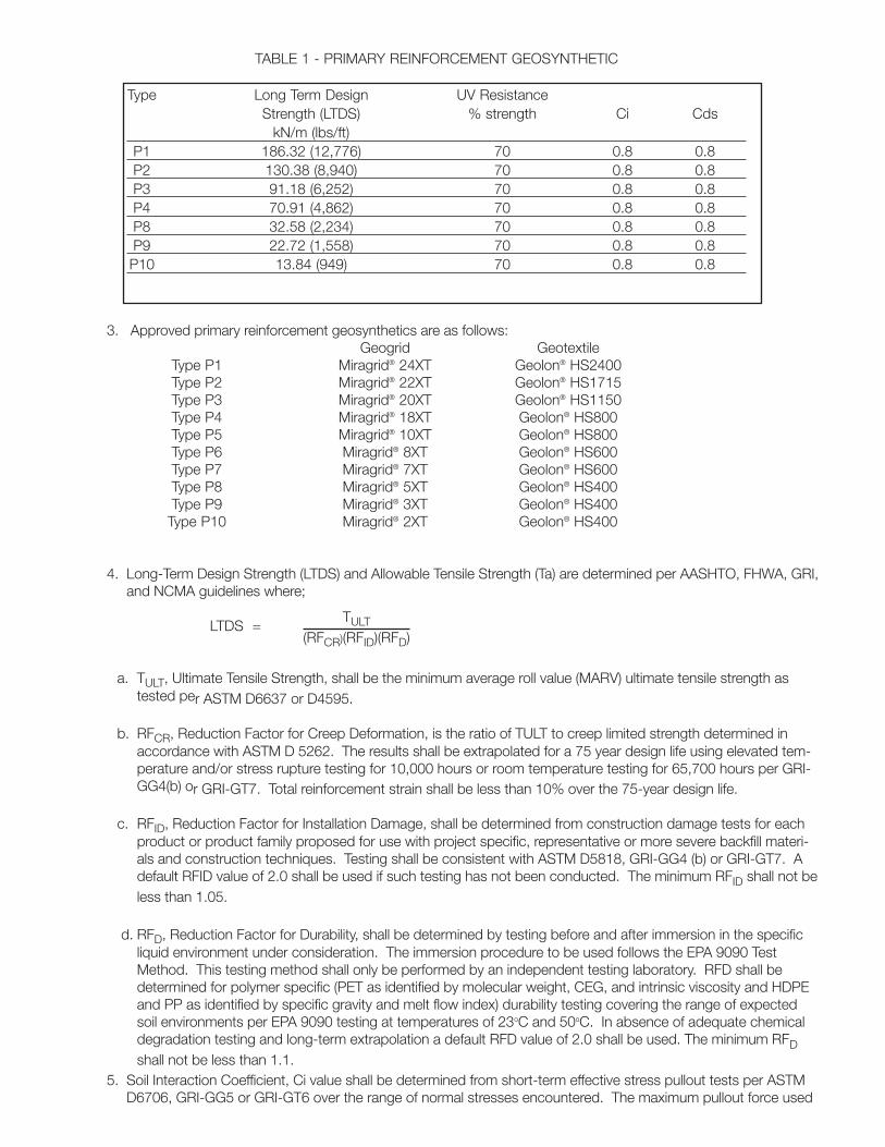
TABLE 1 - PRIMARY REINFORCEMENT GEOSYNTHETIC
Type Long Term Design UV ResistanceStrength (LTDS) % strength Ci Cds
kN/m (lbs/ft)P1 186.32 (12,776) 70 0.8 0.8P2 130.38 (8,940) 70 0.8 0.8P3 91.18 (6,252) 70 0.8 0.8P4 70.91 (4,862) 70 0.8 0.8P8 32.58 (2,234) 70 0.8 0.8P9 22.72 (1,558) 70 0.8 0.8P10 13.84 (949) 70 0.8 0.8
3. Approved primary reinforcement geosynthetics are as follows: Geogrid Geotextile
Type P1 Miragrid® 24XT Geolon® HS2400Type P2 Miragrid® 22XT Geolon® HS1715Type P3 Miragrid® 20XT Geolon® HS1150Type P4 Miragrid® 18XT Geolon® HS800Type P5 Miragrid® 10XT Geolon® HS800Type P6 Miragrid® 8XT Geolon® HS600Type P7 Miragrid® 7XT Geolon® HS600Type P8 Miragrid® 5XT Geolon® HS400Type P9 Miragrid® 3XT Geolon® HS400Type P10 Miragrid® 2XT Geolon® HS400
4. Long-Term Design Strength (LTDS) and Allowable Tensile Strength (Ta) are determined per AASHTO, FHWA, GRI,and NCMA guidelines where;
LTDS =
a. TULT, Ultimate Tensile Strength, shall be the minimum average roll value (MARV) ultimate tensile strength astested per ASTM D6637 or D4595.
b. RFCR, Reduction Factor for Creep Deformation, is the ratio of TULT to creep limited strength determined inaccordance with ASTM D 5262. The results shall be extrapolated for a 75 year design life using elevated tem-perature and/or stress rupture testing for 10,000 hours or room temperature testing for 65,700 hours per GRI-GG4(b) or GRI-GT7. Total reinforcement strain shall be less than 10% over the 75-year design life.
c. RFID, Reduction Factor for Installation Damage, shall be determined from construction damage tests for eachproduct or product family proposed for use with project specific, representative or more severe backfill materi-als and construction techniques. Testing shall be consistent with ASTM D5818, GRI-GG4 (b) or GRI-GT7. Adefault RFID value of 2.0 shall be used if such testing has not been conducted. The minimum RFID shall not beless than 1.05.
d. RFD, Reduction Factor for Durability, shall be determined by testing before and after immersion in the specificliquid environment under consideration. The immersion procedure to be used follows the EPA 9090 TestMethod. This testing method shall only be performed by an independent testing laboratory. RFD shall bedetermined for polymer specific (PET as identified by molecular weight, CEG, and intrinsic viscosity and HDPEand PP as identified by specific gravity and melt flow index) durability testing covering the range of expectedsoil environments per EPA 9090 testing at temperatures of 23oC and 50oC. In absence of adequate chemicaldegradation testing and long-term extrapolation a default RFD value of 2.0 shall be used. The minimum RFDshall not be less than 1.1.
5. Soil Interaction Coefficient, Ci value shall be determined from short-term effective stress pullout tests per ASTMD6706, GRI-GG5 or GRI-GT6 over the range of normal stresses encountered. The maximum pullout force used
TULT(RFCR)(RFID)(RFD)

to determine Ci shall be limited to the lesser of Ta or the force that yields 1.5 inches displacement. The minimumCi value shall not be less than 0.8, determined as follows:
Ci = F 2LσN tanϕ
where F = Pullout Force (lb/ft), per GRI-GG5 or GRI-GT6L = Geosynthetic Embedment Length in Test (ft)σN = Effective Normal Stress (psf)ϕ = Effective Soil Friction Angle, Degrees
6. Direct Sliding Coefficient, Cds value shall be determined in accordance with ASTM D 5321 over the range of nor-mal stresses encountered. The minimum Cds value shall not be less than 0.8, determined as follows:
Cds = RdsLσN tanϕ
where Rds = Maximum Shear Resistance (lb/ft), per ASTM D 5321L = Stationary Length of Geosynthetic (ft)σN = Effective Normal Stress (psf)ϕ = Effective Soil Friction Angle, Degrees
7. UV Resistance shall be determined in accordance with ASTM D 4355. Geosynthetics shall retain a minimum of70% of the Ultimate Tensile Strength per ASTM D 4595 after UV exposure.
B. Secondary Reinforcement Geosynthetic:1. The geosynthetic shall be manufactured with fibers consisting of long-chain synthetic polymers composed of at
least 95 percent by weight of polyolefins or polyesters. They shall form a stable network such that the filamentsor yarns retain their dimensional stability relative to each other, including selvages.
2. The geosynthetic shall meet the requirements of Table 2. All numeric values in Table 2 represent MARV in theprincipal reinforcement direction.
TABLE 2 - SECONDARY REINFORCEMENT GEOSYNTHETIC
Ultimate Tensile Strength UV Resistance Type ASTM D 4595 ASTM D 4355 %
kN/m (lbs/ft) strength retainedS1 58.33 (4000) 70S2 39.38 (2700) 70S3 29.17 (2000) 70S4 21.88 (1500) 70
3. Approved geosynthetics are as follows:Geogrid Geotextile
Type S1 BasXgrid® 12 Geolon® HP570Type S2 BasXgrid® 11 Geolon® HP370Type S3 BasXgrid® 11 Geolon® HP370Type S4 BasXgrid® 11 Geolon® HP370
2.3 QUALITY CONTROL
A. Manufacturing Quality Control: Testing shall be performed at a laboratory accredited by GAI-LAP and A2LA for testsrequired for the geosynthetic, at frequency meeting or exceeding ASTM D 4354.
B. Ultraviolet Stability shall be verified by an independent laboratory on the geosynthetic or a geosynthetic of similarconstruction and yarn type.

3 EXECUTION
3.1 PREPARATION
A. Foundation soil shall be excavated to the lines and grades as shown on the construction drawings or as directed bythe Engineer. Over-excavated areas shall be filled with compacted backfill material as per project specifications oras directed by the Engineer. As a minimum, foundation soil shall be proof rolled prior to backfill and geosyntheticplacement.
3.2 INSTALLATION
A. Geosynthetic shall be laid at the proper elevation and orientation as shown on the construction drawings or asdirected by the Engineer. Contractor shall verify correct orientation of the geosynthetic.
B. Geosynthetic may be temporarily secured in-place with staples, pins, sand bags or backfill as required by fill proper-ties, fill placement procedure or weather condition, or as directed by the Engineer.
C. Primary geosynthetic may not be overlapped or connected mechanically to form splices in the primary strengthdirection. Single panel lengths are required in the primary strength direction. No overlapping is required betweenadjacent rolls unless specified by the Engineer.
D. Backfill material shall be placed in lifts and compacted as directed under project specifications. Backfill shall beplaced, spread and compacted in such a manner as to minimize the development of wrinkles in and/or movementof the geosynthetic. A minimum fill thickness of 150 mm (6 in) is required prior to the operation of tracked vehiclesover the geosynthetic.
E. Turning of tracked vehicles should be kept to minimum to prevent tracks from displacing the fill and damaging thegeosynthetic. Rubber tired equipment may pass over the geosynthetic reinforcement at low speeds, less than 16km/hr (10 mph). Sudden braking and sharp turns shall be avoided. Any geosynthetic damaged during installationshall be replaced by the Contractor at no additional cost to the Owner.
END OF SECTION
INSTALLATION GUIDELINES FOR GEOSYNTHETIC REINFORCED STEEPENED SLOPES
This document is prepared to help ensure that the geosynthetic reinforced soil slope, once installed, will perform itsintended design function. To do so, the geosynthetic must be identified, handled, stored, and installed in such a waythat its physical property values are not affected and that the design conditions are ultimately met as intended. Thisdocument contains information consistent with generally accepted methods of identifying, handling, storing andinstalling geosynthetic materials. Failure to follow these guidelines may result in the unnecessary failure of the geosyn-thetic in a properly designed application.
Material Identification, Storage and Handling
The geotextile shall be rolled on cores having strength sufficient to avoid collapse or other damage from normal use.Each roll shall be wrapped with a plastic covering to protect the geosynthetic from damage during shipping and han-dling, and shall be identified with a durable gummed label or the equivalent, clearly readable on the outside of thewrapping for the roll. The label shall show the manufacturer's name, the style number, and the roll number. Roll identifi-cation corresponding to the proposed location of the roll as shown on the construction drawings and as approved bythe Engineer, Owner and Contractor can be provided.
While unloading or transferring the geosynthetic from one location to another, prevent damage to the wrapping, core,label, or to the geosynthetic itself. If the geosynthetic is to be stored for an extended period of time, the geosyntheticshall be located and placed in a manner that ensures the integrity of the wrapping, core, and label as well as the physicalproperties of geosynthetic. This can be accomplished by elevating the geosynthetic off the ground on dunnage andensuring that it is adequately covered and protected from ultraviolet radiation including sunlight, chemicals that are strongacids or strong bases, fire or flames including welding sparks, temperatures in excess of 60C (140F), and human or ani-mal destruction.
Foundation Soil/Subgrade PreparationPrepare the surface on which the geosynthetic is to be placed so that no damage to the geosynthetic will occur.Foundation/subgrade soil should be excavated to the lines and grades as shown on the construction drawings oras directed by the Engineer. Over excavated areas should be filled with compacted backfill material as directed by theEngineer. The foundation/subgrade soil should be cleared of all deleterious materials and the surface should besmooth and level such that any shallow depressions and humps do not exceed 6 in (15 cm) in depth and height.The foundation/subgrade soils should be proofrolled prior to geosynthetic and backfill placement. This exercise shouldbe performed prior to each successive geosynthetic layer that is installed.
The foundation soils shall be compacted to 95 percent of optimum dry density and plus or minus three (3) percent-age points of the optimum moisture content, according to test method ASTM D698 or as specified by the Engineer. Itis recommended that cohesive soils be compacted in maximum lifts of 6 in (15 cm) to 8 in (20 cm) and granular soils inlifts of 9 in (23 cm) to 12 in (30 cm) compacted thickness.
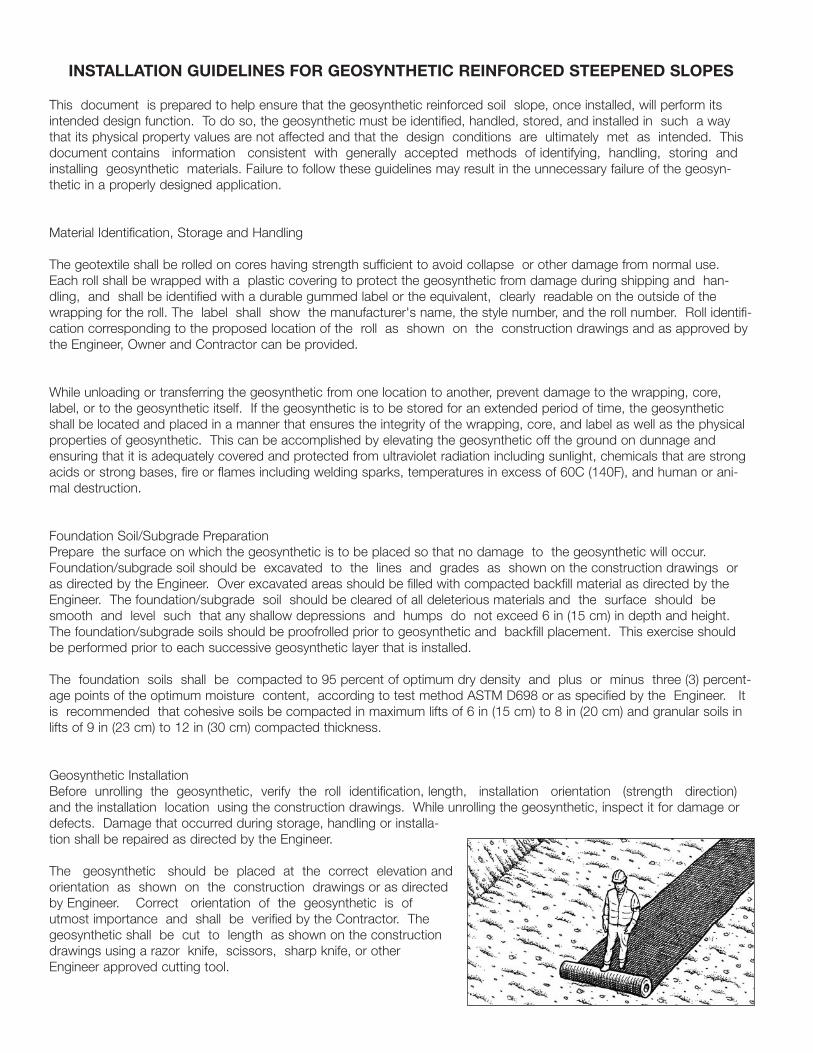
Geosynthetic InstallationBefore unrolling the geosynthetic, verify the roll identification, length, installation orientation (strength direction)and the installation location using the construction drawings. While unrolling the geosynthetic, inspect it for damage ordefects. Damage that occurred during storage, handling or installa-tion shall be repaired as directed by the Engineer.
The geosynthetic should be placed at the correct elevation andorientation as shown on the construction drawings or as directedby Engineer. Correct orientation of the geosynthetic is ofutmost importance and shall be verified by the Contractor. Thegeosynthetic shall be cut to length as shown on the constructiondrawings using a razor knife, scissors, sharp knife, or otherEngineer approved cutting tool.
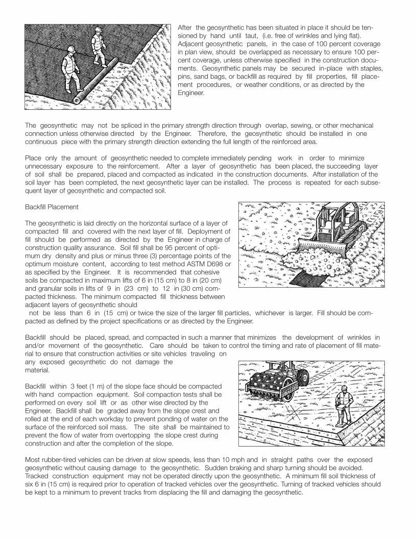
After the geosynthetic has been situated in place it should be ten-sioned by hand until taut, (i.e. free of wrinkles and lying flat).Adjacent geosynthetic panels, in the case of 100 percent coveragein plan view, should be overlapped as necessary to ensure 100 per-cent coverage, unless otherwise specified in the construction docu-ments. Geosynthetic panels may be secured in-place with staples,pins, sand bags, or backfill as required by fill properties, fill place-ment procedures, or weather conditions, or as directed by theEngineer.
The geosynthetic may not be spliced in the primary strength direction through overlap, sewing, or other mechanicalconnection unless otherwise directed by the Engineer. Therefore, the geosynthetic should be installed in onecontinuous piece with the primary strength direction extending the full length of the reinforced area.
Place only the amount of geosynthetic needed to complete immediately pending work in order to minimizeunnecessary exposure to the reinforcement. After a layer of geosynthetic has been placed, the succeeding layerof soil shall be prepared, placed and compacted as indicated in the construction documents. After installation of thesoil layer has been completed, the next geosynthetic layer can be installed. The process is repeated for each subse-quent layer of geosynthetic and compacted soil.
Backfill Placement
The geosynthetic is laid directly on the horizontal surface of a layer ofcompacted fill and covered with the next layer of fill. Deployment offill should be performed as directed by the Engineer in charge ofconstruction quality assurance. Soil fill shall be 95 percent of opti-mum dry density and plus or minus three (3) percentage points of theoptimum moisture content, according to test method ASTM D698 oras specified by the Engineer. It is recommended that cohesivesoils be compacted in maximum lifts of 6 in (15 cm) to 8 in (20 cm)and granular soils in lifts of 9 in (23 cm) to 12 in (30 cm) com-pacted thickness. The minimum compacted fill thickness betweenadjacent layers of geosynthetic should
not be less than 6 in (15 cm) or twice the size of the larger fill particles, whichever is larger. Fill should be com-pacted as defined by the project specifications or as directed by the Engineer.
Backfill should be placed, spread, and compacted in such a manner that minimizes the development of wrinkles inand/or movement of the geosynthetic. Care should be taken to control the timing and rate of placement of fill mate-rial to ensure that construction activities or site vehicles traveling onany exposed geosynthetic do not damage thematerial.
Backfill within 3 feet (1 m) of the slope face should be compactedwith hand compaction equipment. Soil compaction tests shall beperformed on every soil lift or as other wise directed by theEngineer. Backfill shall be graded away from the slope crest androlled at the end of each workday to prevent ponding of water on thesurface of the reinforced soil mass. The site shall be maintained toprevent the flow of water from overtopping the slope crest duringconstruction and after the completion of the slope.
Most rubber-tired vehicles can be driven at slow speeds, less than 10 mph and in straight paths over the exposedgeosynthetic without causing damage to the geosynthetic. Sudden braking and sharp turning should be avoided.Tracked construction equipment may not be operated directly upon the geosynthetic. A minimum fill soil thickness ofsix 6 in (15 cm) is required prior to operation of tracked vehicles over the geosynthetic. Turning of tracked vehicles shouldbe kept to a minimum to prevent tracks from displacing the fill and damaging the geosynthetic.

Drainage
Groundwater infiltration and/or surface water runoff can cause saturation of the reinforced fill soil that will significantlyreduce soil strength and reduce the stability of the reinforced mass. If the slope was not designed with extra reinforce-ment to handle these reduced soil strengths, then an engineered drainage system should be provided to prevent the fillfrom becoming saturated.
Protection of the Slope Face
For reinforced slopes, 1:1 V or flatter, the slope face is hydroseeded and covered with a material that will retain soilparticles and promote vegetative growth. For slopes steeper than 1:1 V or in areas where vegetation is difficult toestablish, the slope can be treated with durable facing (i.e. wire L-baskets, shotcrete, landscaping timbers, gabions,etc.).


![Synthetics Compendium A4 Sheets[1][1]](https://static.fdocuments.in/doc/165x107/545fb886af79593c758b4f51/synthetics-compendium-a4-sheets11.jpg)
