Genesis 2 Measuring System - Chief Technology...nated the damage, Genesis 2 computerized measuring...
42
Genesis 2 Measuring System R Owners Manual 1999 © Chief Automotive Systems, Inc.
Transcript of Genesis 2 Measuring System - Chief Technology...nated the damage, Genesis 2 computerized measuring...
Genesis 2 Measuring System
R
Owners Manual
1999 © Chief Automotive Systems, Inc.
GENESIS 2OWNERS MANUAL
R
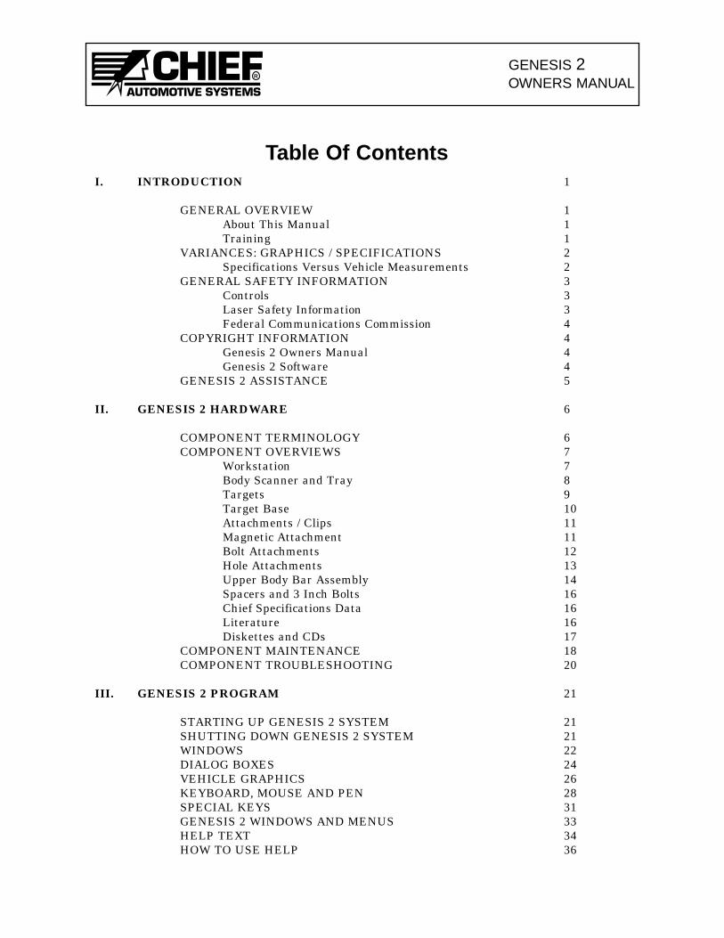
Table Of ContentsI. INTRODUCTION 1
GENERAL OVERVIEW 1About This Manual 1Training 1
VARIANCES: GRAPHICS / SPECIFICATIONS 2Specifications Versus Vehicle Measurements 2
GENERAL SAFETY INFORMATION 3Controls 3Laser Safety Information 3Federal Communications Commission 4
COPYRIGHT INFORMATION 4Genesis 2 Owners Manual 4Genesis 2 Software 4
GENESIS 2 ASSISTANCE 5
II. GENESIS 2 HARDWARE 6
COMPONENT TERMINOLOGY 6COMPONENT OVERVIEWS 7
Workstation 7Body Scanner and Tray 8Targets 9Target Base 10Attachments / Clips 11Magnetic Attachment 11Bolt Attachments 12Hole Attachments 13Upper Body Bar Assembly 14Spacers and 3 Inch Bolts 16Chief Specifications Data 16Literature 16Diskettes and CDs 17
COMPONENT MAINTENANCE 18COMPONENT TROUBLESHOOTING 20
III. GENESIS 2 PROGRAM 21
STARTING UP GENESIS 2 SYSTEM 21SHUTTING DOWN GENESIS 2 SYSTEM 21WINDOWS 22DIALOG BOXES 24VEHICLE GRAPHICS 26KEYBOARD, MOUSE AND PEN 28SPECIAL KEYS 31GENESIS 2 WINDOWS AND MENUS 33HELP TEXT 34HOW TO USE HELP 36

GENESIS 2OWNERS MANUAL
R
GENESIS 2 COMPUTERIZED MEASURING SYSTEM LIMITED WARRANTY AGREEMENT
Chief Automotive Systems, Inc. warrants for one year from date of purchase any components of its Genesis 2Computerized Measuring System and three years for its Genesis 2 Gold Computerized Measuring Systemwhich do not perform satisfactorily due to defect caused by faulty material or workmanship. THE WARRAN-TY DESCRIBED HEREIN SHALL BE IN LIEU OF ANY OTHER WARRANTY, EXPRESS OR IMPLIED,INCLUDING BUT NOT LIMITED TO, ANY IMPLIED WARRANTY OF MERCHANTABILITY, OF FITNESSFOR A PARTICULAR PURPOSE, OF TITLE, OR OTHERWISE ON THE PART OF CHIEF AUTOMOTIVESYSTEMS, INC. AND MITCHELL INTERNATIONAL REGARDING THE EQUIPMENT, THE SPECIFICA-TIONS CONTAINED THEREIN OR ANY UNIT THEREOF. Chief's obligation under this warranty is limit-ed to the repair or replacement of components which are defective and which have not been misused, carelesslyhandled, or defaced by the repair or repairs made or attempted by others. Chief Automotive Systems, Inc. doesnot assume responsibility for any injury or property damage resulting from the operator's misuse of this prod-uct. Unless a statement made by any representative of Chief Automotive Systems, Inc. is identified as a war-ranty, any such statements shall not be construed to constitute warranties and do not form part of the basisof the bargain; it being expressly understood that such statements are merely made in the course of the nego-tiations of the parties. FURTHERMORE, Chief Automotive Systems, Inc. specifically excludes or disclaimsany warranty, express or implied, based on any sample or model shown by Chief Automotive Systems, Inc. tothe buyer for demonstration purposes only.
LIMITATION OF REMEDIES. The parties agree that the buyer's sole and exclusive remedy against ChiefAutomotive Systems, Inc. shall be for the repair or replacement of components which are defective and whichhave not been misused, carelessly handled, or defaced by the repair or repairs made or attempted by others.The buyer agrees that no other remedy (including, but not limited to, incidental or consequential damages forlost profits, lost sales, injury to person or property, or any other incidental or consequential loss) shall be avail-able to him. This exclusive remedy shall not be deemed as to have failed of its essential purpose so long asChief Automotive Systems, Inc. is willing and able to repair or replace defective parts in the prescribed man-ner.
Prior to the return of any merchandise for a warranty claim, contact the Customer ServiceDepartment (800-445-9262) for a Returned Goods Authorization Number and instructions. Nogoods may be returned without a Returned Goods Authorization Number.
The buyer shall be required to deliver the defective part to Chief Automotive Systems, Inc. UNLESS (1) thepart was destroyed as a result of its defect or of any defect in any part covered in this warranty, AND (2) Chiefis reasonably satisfied that the part was defective at the time of its failure.
DISCLAIMER OF WARRANTYTHE GRAPHICS AND DATA SUPPLIED WITH THE GENESIS 2 SYSTEM HAVE BEEN COMPILEDFROM AUTHORITATIVE SOURCES. EVERY EFFORT HAS BEEN MADE BY CHIEFAUTOMOTIVE SYSTEMS, INC., TO ASSURE ACCURACY; HOWEVER, MANUFACTURINGCHANGES, ERRORS OR OMISSIONS MIGHT OCCUR. CHIEF AUTOMOTIVE SYSTEMS, INC.DOES NOT ASSUME RESPONSIBILITY NOR CAN IT BE HELD RESPONSIBLE FOR THE LOSSOR DAMAGE RESULTING FROM VEHICLE MANUFACTURER'S CHANGES, ERRORS, OR OMIS-SIONS IN THIS SYSTEM.
GENESIS 2 COMPUTERIZED MEASURING SYSTEM WARRANTY REGISTRATION FORM
Please fill out completely and detach from Genesis 2 Owners Manual. Return form to:
Chief Automotive Systems, Inc., Box 1368, Grand Island, Ne. 68802-1368
Accepted this __________ day of ___________________________________, 19 _____.
Serial Numbers:
System ______________________
Body Scanner ________________
Computer____________________
Monitor______________________
Printer_______________________
Shop Name: __________________________________________________
Address: _____________________________________________________
City, State, Zip: ________________________________________________
By: _________________________________________________________
Title: ________________________________________________________

GENESIS 2OWNERS MANUAL
I. INTRODUCTION
GENERAL OVERVIEW
Whether detecting misalignment in a vehicle’s structure or verifying repairs have elimi-nated the damage, Genesis 2 computerized measuring system can do the job. Genesis 2integrates the precision of laser scanning with a computerized data base for unmatchedaccuracy in collision repair and analysis. In addition to showing extent of collision dam-age, Genesis 2 monitors progress throughout the repair and verifies the vehicle’s struc-ture is correctly aligned. Printed reports verify the vehicle’s structural condition byshowing overhead diagrams that display centerline, datum line and datum height mea-surements.
The Genesis 2 system measures on the principle of triangulation. The system’s electronicBody Scanner houses two rotating Laser Lights that project toward light-reflectiveTargets (each bearing a unique code) that are suspended from vehicle’s reference points.The Body Scanner houses two photo sensors that identify the angle of revolving laserreflections. This information is transferred to the computer which performs the triangu-lation and Target identification functions.
About This Manual
This manual provides information on basic hardware components. It also provides perti-nent information regarding startup/shutdown procedures, examples of on-screenWindows/Dialog Boxes and Vehicle Graphics, Keyboard/Mouse/Pen functions, SpecialKeys, and information on how to use the Genesis 2 Help Text. Pertinent software func-tions and parts ordering information appear in the Genesis 2 Basic Training Manual andGenesis 2 Parts Manual.
Chief Automotive Systems, Inc. reserves the right to alter product specifica-tions and/or package components without notice. Also, components shown inthis manual may vary slightly in appearance from those that are actually sup-plied with the Genesis 2 computerized measuring system.
Training
Chief Automotive Systems, Inc. also offers professional training. For maximum produc-tivity and equipment utilization, each person operating a Genesis 2 computerized mea-suring system should receive training conducted by Chief Training Department person-el. For information about training locations and dates, contact Chief AutomotiveSystems, Inc., P.O. Box 1368, 1924 East Fourth St., Grand Island, Nebraska 68802-1368,308/384-9747, Attn: Training Department School Coordinator or contact your local rep-resentative.
1
R

GENESIS 2OWNERS MANUAL
VARIANCES: GRAPHICS/SPECIFICATIONS
Graphics
The Graphics displayed by the Genesis 2 computerized measuring system are of high quali-ty and have been checked for accuracy, but may not reflect the vehicle’s actual appearance inevery detail. Variances may exist as a result of changes made by vehicle manufacturers ordetails omitted as a result of space limitations.
Specifications Versus Vehicle Measurements
A vehicle’s final measurements may vary from specifications listed and still be aligned cor-rectly. Variances between vehicle measurements and specifications result from one or a com-bination of the following conditions:
• Vehicle specifications are compiled from vehicle manufacturer’s engineering drawingsand/or the measuring of new (undamaged) vehicles.
• Most vehicle manufacturers control only a small number of reference points on vehicle’slower structure. These reference points are commonly referred to as master control points,class one control points, principle locating points, etc. Each of these control points is usu-ally held to a tolerance of plus or minus 3mm in three dimensions (length, width, height).Other reference points have a larger tolerance, but generally, a tolerance of plus or minus5mm in three dimensions (length, width, height) is considered ‘normal’ according to ChiefAutomotive Systems, Inc. experience. In Arrow Display Mode, reference point measure-ments that exceed tolerance appear in ‘red’ whereas those falling within tolerance appearin ‘blue’.
• Some reference points used for dimensioning the same make and model of vehicle varyfrom one manufacturing plant to another. Also, periodic manufacturing improvements canaffect the location of points used for dimensioning.
Key points to remember when realigning a vehicle:
• Length and width dimensions on each side of vehicle should be within plus or minus 3mmof each other when control or reference points are symmetrical. Frequently, the height atfront and rear of vehicle will exceed this tolerance according to Chief Automotive Systems,Inc. experience.
• When excessive pressure is needed near end of realignment process, and when area aroundspot welds begins to deform, ‘stop pulling’ and ‘re-evaluate the repair’. This situation usu-ally occurs when a vehicle’s components were not placed on specification during manufac-ture. In this case, continuing to pull in an attempt to achieve an exact specification mayactually damage the vehicle.
• When a vehicle’s dimensions vary beyond ‘normal’ tolerances, it is the repair technician’sresponsibility to determine if dimensional variances will affect suspension and steeringalignment, the safe operation and handling of vehicle, and alignment of body panels.
2
R
GENESIS 2OWNERS MANUAL
R
3
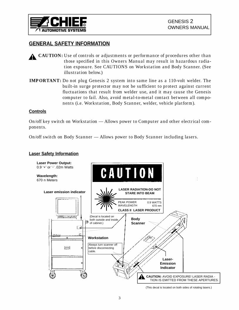
Always turn scanner offbefore disconnectingcable.
Laser emission indicator
BodyScanner
Workstation
Laser-EmissionIndicator
CAUTION: AVOID EXPOSURE! LASER RADIA -TION IS EMITTED FROM THESE APERTURES.
!
(This decal is located on both sides of rotating lasers.)
Laser Power Output:0.9 ‘+’ or ‘-’ .02m Watts
Wavelength:670 n Meters
(Decal is located onboth outside and insideof cabinet.)
LASER RADIATION-DO NOTSTARE INTO BEAM
PEAK POWERWAVELENGTH
0.9 WATTS670 nm
CLASS II LASER PRODUCT
GENERAL SAFETY INFORMATION
! CAUTION: Use of controls or adjustments or performance of procedures other thanthose specified in this Owners Manual may result in hazardous radia-tion exposure. See CAUTIONS on Workstation and Body Scanner. (Seeillustration below.)
IMPORTANT: Do not plug Genesis 2 system into same line as a 110-volt welder. Thebuilt-in surge protector may not be sufficient to protect against currentfluctuations that result from welder use, and it may cause the Genesiscomputer to fail. Also, avoid metal-to-metal contact between all compo-nents (i.e. Workstation, Body Scanner, welder, vehicle platform).
Controls
On/off key switch on Workstation — Allows power to Computer and other electrical com-ponents.
On/off switch on Body Scanner — Allows power to Body Scanner including lasers.
Laser Safety Information
General Safety Information (continued)
Federal Communications Commission
Genesis 2 computerized measuring system has been tested and found to comply with lim-its for a Class A digital device, pursuant to Part 15 of the FCC Rules. These limits aredesigned to provide reasonable protection against harmful interference when equipmentis operated in a commercial environment. This equipment generates, uses, and can radi-ate radio frequency energy and, if not installed and used in accordance with owners andtraining manuals provided, may cause harmful interference to radio communications.Operation of this equipment in a residential area is likely to cause harmful interferencein which case the user will be required to correct the interference at his own expense.
COPYRIGHT INFORMATION
Genesis 2 Owners Manual
Chief Automotive Systems, Inc. © 1999. All Rights Reserved. No part of this work coveredby copyrights hereon may be reproduced or copied in any form or by any means includ-ing, but not limited to, graphics, electronic, or mechanical, including photocopying, tap-ing, printing or information storage and retrieval systems — without written permissionof Chief Automotive Systems, Inc., Grand Island, Nebraska, U.S.A. All inquiries relatingto use of this information should be addressed to Chief Automotive Systems, Inc., Tel (+)800-445-9262, Fax (+1) 308-384-8966.
Genesis 2 Software
Chief Automotive Systems, Inc. © 1999. All Rights Reserved. No part of this work coveredby copyrights hereon may be reproduced or copied in any form or by any means includ-ing, but not limited to, graphics, electronic, or mechanical, including photocopying, tap-ing, printing or information storage and retrieval systems — without written permissionof Chief Automotive Systems, Inc., Grand Island, Nebraska, U.S.A. All inquiries relatingto use of this information should be addressed to Chief Automotive Systems, Inc., Tel (+)800-445-9262, Fax (+1) 308-384-8966.
Portions © Iterated Systems, Inc. 1990-1993. All Rights Reserved. Fractal image com-pression and decompression are covered by U.S. patents and other international patentsbelonging to Iterated Systems, Inc. All inquiries relating to use of the technology shouldbe addressed to Iterated Systems, Inc. Tel (+1) 404-840-0633, Fax (+1) 404-840-0806.
4
GENESIS 2OWNERS MANUAL
R
GENESIS 2OWNERS MANUAL
R
GENESIS 2 ASSISTANCE
Chief Automotive Systems, Inc. offers assistance to Genesis 2 program operators. Whencontacting Chief Automotive Systems, Inc., operators should be prepared to give theirname, telephone number (including area code), version of software in use and nature ofproblem encountered. To identify version of software in use, select ‘About’ from list ofitems under Help heading in any Menu Bar. In U.S.A., call toll free 800-445-9262, ext.333. If outside U.S.A., contact an authorized Chief Automotive Systems, Inc. representa-tive.
Computer Program Updates
Updates and changes to computer programs will be issued from time to time via com-puter CDs. Explanations of changes and instructions for installing them will accompanythe CDs.
Specification Updates/Corrections
Annually, and as required, updates and additions to vehicle specifications (and instruc-tions for installation) will be made available for purchase.
Keeping Records of Service and Updates
Owners should keep records of services performed and updates provided. These recordswill be helpful when placing calls to the toll free support number.
5
GENESIS 2OWNERS MANUAL
R
II. GENESIS 2 HARDWARE
COMPONENT TERMINOLOGY
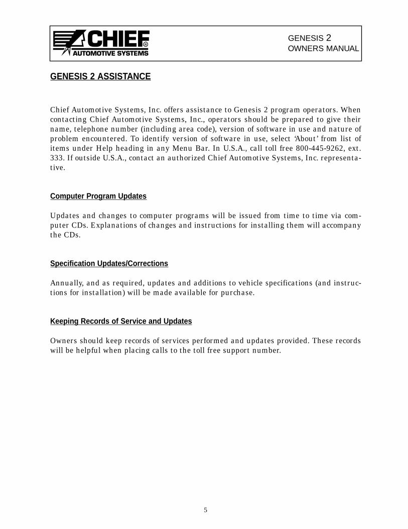
Equipment in Chief ’s Genesis 2 Computerized Measuring System (see Figure 1) is easyto use and provides accurate readings. Its basic components include:
• Computer [1] • Targets [8] and Attachments/Clips [9]• Display Monitor [2] • Upper Body Bar [10]• Keyboard [3] • Anchoring Spacer [*]• Printer [4] • Literature [*]• Workstation [5] (*Not shown in Figure 1 — see following• Power Supply [*] pages)• Body Scanner [6] and Tray [7]
6
10
68 2
3
4
1
5
7
9
Figure 1
! CAUTION: Use of controls, adjustments or performance of procedures other than those specified in this manual may result in a breach of warranty andcould result in hazardous radiation exposure. See CAUTIONS onWorkstation and Body Scanner.
(Optional)
GENESIS 2OWNERS MANUAL
R
COMPONENT OVERVIEWS
Workstation
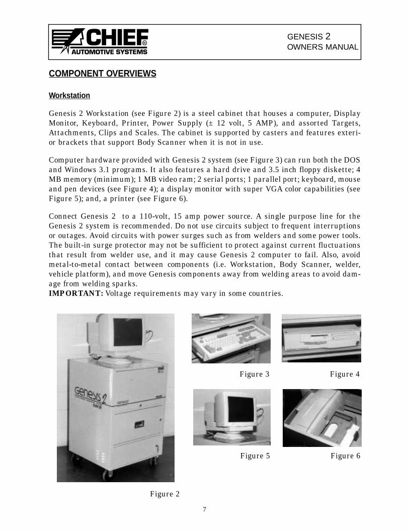
Genesis 2 Workstation (see Figure 2) is a steel cabinet that houses a computer, DisplayMonitor, Keyboard, Printer, Power Supply (± 12 volt, 5 AMP), and assorted Targets,Attachments, Clips and Scales. The cabinet is supported by casters and features exteri-or brackets that support Body Scanner when it is not in use.
Computer hardware provided with Genesis 2 system (see Figure 3) can run both the DOSand Windows 3.1 programs. It also features a hard drive and 3.5 inch floppy diskette; 4MB memory (minimum); 1 MB video ram; 2 serial ports; 1 parallel port; keyboard, mouseand pen devices (see Figure 4); a display monitor with super VGA color capabilities (seeFigure 5); and, a printer (see Figure 6).
Connect Genesis 2 to a 110-volt, 15 amp power source. A single purpose line for theGenesis 2 system is recommended. Do not use circuits subject to frequent interruptionsor outages. Avoid circuits with power surges such as from welders and some power tools.The built-in surge protector may not be sufficient to protect against current fluctuationsthat result from welder use, and it may cause Genesis 2 computer to fail. Also, avoidmetal-to-metal contact between components (i.e. Workstation, Body Scanner, welder,vehicle platform), and move Genesis components away from welding areas to avoid dam-age from welding sparks.IMPORTANT: Voltage requirements may vary in some countries.
7
Figure 2
Figure 3 Figure 4
Figure 5 Figure 6
GENESIS 2OWNERS MANUAL
R
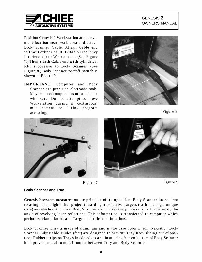
Body Scanner and Tray
Genesis 2 system measures on the principle of triangulation. Body Scanner houses tworotating Laser Lights that project toward light reflective Targets (each bearing a uniquecode) on vehicle’s structure. Body Scanner also houses two photo sensors that identify theangle of revolving laser reflections. This information is transferred to computer whichperforms triangulation and Target identification functions.
Body Scanner Tray is made of aluminum and is the base upon which to position BodyScanner. Adjustable guides (feet) are designed to prevent Tray from sliding out of posi-tion. Rubber strips on Tray’s inside edges and insulating feet on bottom of Body Scannerhelp prevent metal-to-metal contact between Tray and Body Scanner.
8
Figure 7 Figure 9
Position Genesis 2 Workstation at a conve-nient location near work area and attachBody Scanner Cable. Attach Cable endwithout cylindrical RFI (Radio FrequencyInterference) to Workstation. (See Figure7.) Then attach Cable end with cylindricalRFI suppressor to Body Scanner. (SeeFigure 8.) Body Scanner ‘on’/’off ’ switch isshown in Figure 9.
IMPORTANT: Computer and BodyScanner are precision electronic tools.Movement of components must be donewith care. Do not attempt to moveWorkstation during a ‘continuous’measurement or during programaccessing. Figure 8
GENESIS 2OWNERS MANUAL
R
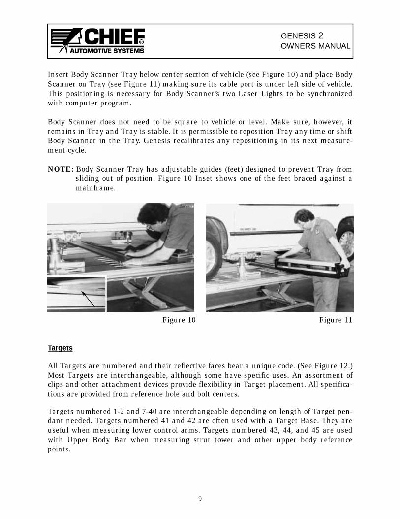
Insert Body Scanner Tray below center section of vehicle (see Figure 10) and place BodyScanner on Tray (see Figure 11) making sure its cable port is under left side of vehicle.This positioning is necessary for Body Scanner’s two Laser Lights to be synchronizedwith computer program.
Body Scanner does not need to be square to vehicle or level. Make sure, however, itremains in Tray and Tray is stable. It is permissible to reposition Tray any time or shiftBody Scanner in the Tray. Genesis recalibrates any repositioning in its next measure-ment cycle.
NOTE: Body Scanner Tray has adjustable guides (feet) designed to prevent Tray fromsliding out of position. Figure 10 Inset shows one of the feet braced against amainframe.
Figure 10 Figure 11
Targets
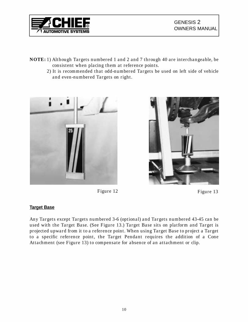
All Targets are numbered and their reflective faces bear a unique code. (See Figure 12.)Most Targets are interchangeable, although some have specific uses. An assortment ofclips and other attachment devices provide flexibility in Target placement. All specifica-tions are provided from reference hole and bolt centers.
Targets numbered 1-2 and 7-40 are interchangeable depending on length of Target pen-dant needed. Targets numbered 41 and 42 are often used with a Target Base. They areuseful when measuring lower control arms. Targets numbered 43, 44, and 45 are usedwith Upper Body Bar when measuring strut tower and other upper body referencepoints.
9
GENESIS 2OWNERS MANUAL
R
NOTE: 1) Although Targets numbered 1 and 2 and 7 through 40 are interchangeable, beconsistent when placing them at reference points.
2) It is recommended that odd-numbered Targets be used on left side of vehicleand even-numbered Targets on right.
Target Base
Any Targets except Targets numbered 3-6 (optional) and Targets numbered 43-45 can beused with the Target Base. (See Figure 13.) Target Base sits on platform and Target isprojected upward from it to a reference point. When using Target Base to project a Targetto a specific reference point, the Target Pendant requires the addition of a ConeAttachment (see Figure 13) to compensate for absence of an attachment or clip.
10
Figure 12 Figure 13

GENESIS 2OWNERS MANUAL
R
Attachments and Clips
A variety of Attachments and Clips allow Targets to be mounted to practically any ref-erence hole or bolt. These include Magnetic Attachments, Bolt Attachments, andReference Hole Attachments.
Magnetic Attachment
Magnetic Attachments (see Figures 14 and 15) are used on bottom of structural memberswhen reference holes or other mounting locations are not accessible. This attachment,used primarily for comparative measurements, should be positioned so that its verticalsurface is flush with vertical surface of structural member it mounts to. The Target canthen be mounted in attachment’s clip.
The magnet on the attachment is strong and will maintain its holding power if cared forproperly. A Magnet Keeper (see Inset — Figure 15) should be positioned on magnet whenthe attachment is not in use.
IMPORTANT: Never use arc welder or heat near Magnetic Attachment as this tends toreduce its holding power.
Figure 15
Figure 14
11

GENESIS 2OWNERS MANUAL
R
Bolt Attachments
Nylon Base ‘Bolt Attachments’ have a strong gripping capability and are designed to fitthe wide range of bolts (and nuts) used on a vehicle’s structure. The small size graspsbolts/nuts with a 10 to 20mm diameter. The medium size grasps bolts/nuts with a 15 to25mm diameter, and the large size grasps bolts/nuts with a 25 to 35mm diameter.
The Nylon Base Attachments work equally well on the bottom of a structural componentor on the side of a structural component. (See Figure 16 and its Inset.) The nylon baseswivels to allow for easy Target adjustments.IMPORTANT: Bolt Attachments (Metal Clip style) previously supplied with Genesis 2
systems can still be used to mount Targets. The current Genesis 2 pro-gram, however, assumes existing Bolt Attachments (Nylon Base) are inuse until operator inputs correct information in Change AttachmentDialog Box.
Magnetic Bolt Head Attachments - (Optional) also have a strong gripping capability andare designed to fit a wide range of bolt heads. (Figure 17 and its inset show an exampleof a magnetic bolt head attachment.)
Threaded Attachments - (Optional) allow operator to thread the attachment onto extrud-ing bolt threads. (Figure 18 and its inset show an example of a threaded attachment.)
12
Figure 17Figure 16
Figure 18

GENESIS 2OWNERS MANUAL
R
Hole Attachments (Nylon Base)
Reference Hole Attachments are designed to snap into all types of reference holes. Theattachments are made of aluminum and are provided in varying sizes ranging from10mm to 32mm in diameter. In the Genesis 2 program these attachments are identifiedas Aluminum Snap-Ins.
Reference Hole Attachments work equally well on the bottom of a structural componentor on the side of a structural component. (See Figures 19 and 20.) Each attachment (seeInset Figure 18) features a nylon base which swivels to allow for easy Target adjustments.
In addition to the aluminum attachments, a small metal clip is provided for mountingTargets to reference holes measuring 5 to 10mm in diameter. (See Figure 21.)
IMPORTANT: 1) When using Reference Hole Attachments (Nylon Base) in elongated(oval) reference holes, refer to Point Information Dialog Box for cor-rect positioning.
2) Reference Hole Attachments (Metal Clip Style) that were previouslysupplied with Genesis 2 systems can still be used to mount Targets.Current Genesis 2 program, however, assumes existing ReferenceHole Attachments (Nylon Base) are in use until operator inputs cor-rect information in Change Attachment Dialog Box.
13
Figure 20
Figure 21
Figure 19
GENESIS 2OWNERS MANUAL
R
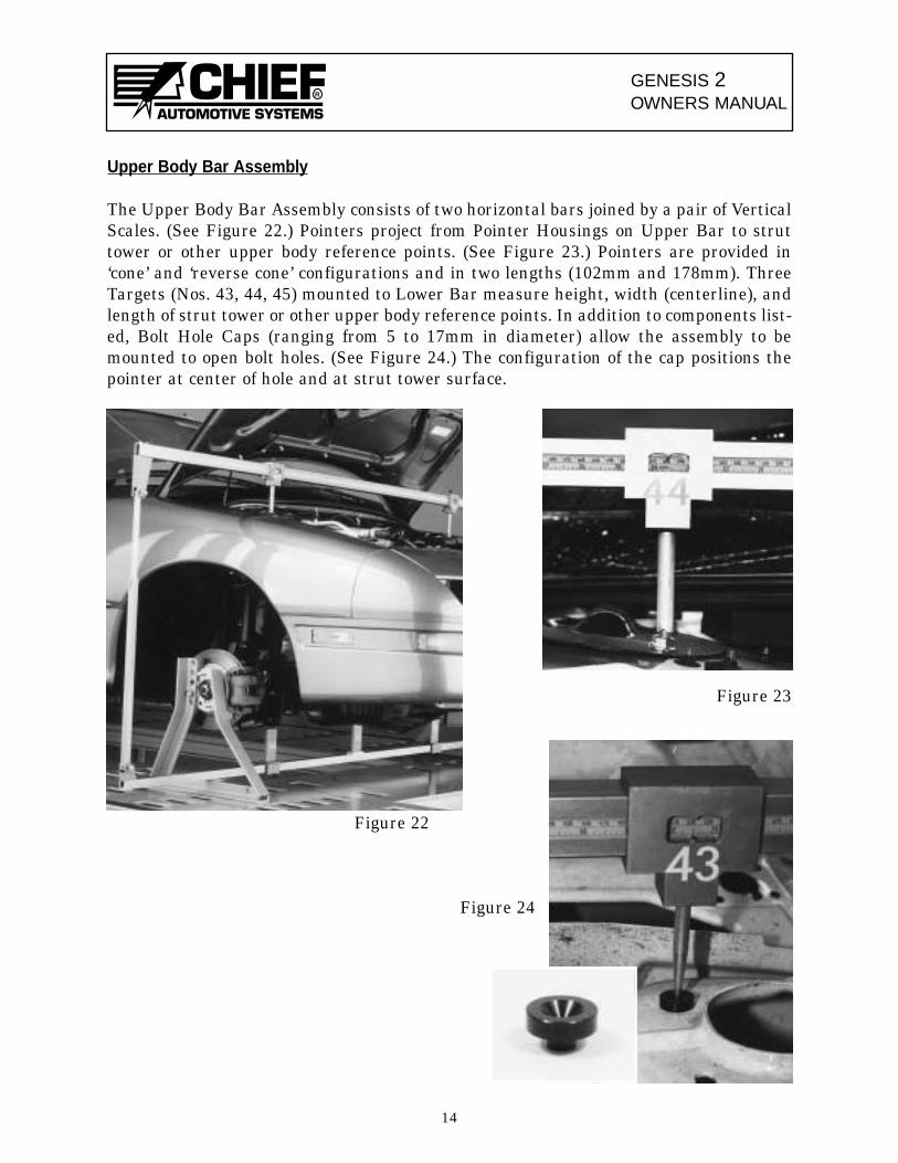
Upper Body Bar Assembly
The Upper Body Bar Assembly consists of two horizontal bars joined by a pair of VerticalScales. (See Figure 22.) Pointers project from Pointer Housings on Upper Bar to struttower or other upper body reference points. (See Figure 23.) Pointers are provided in‘cone’ and ‘reverse cone’ configurations and in two lengths (102mm and 178mm). ThreeTargets (Nos. 43, 44, 45) mounted to Lower Bar measure height, width (centerline), andlength of strut tower or other upper body reference points. In addition to components list-ed, Bolt Hole Caps (ranging from 5 to 17mm in diameter) allow the assembly to bemounted to open bolt holes. (See Figure 24.) The configuration of the cap positions thepointer at center of hole and at strut tower surface.
Figure 23
Figure 22
Figure 24
14
GENESIS 2OWNERS MANUAL
R
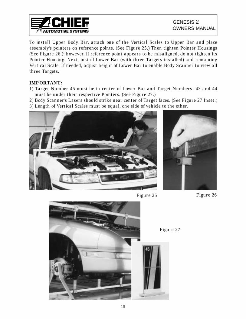
To install Upper Body Bar, attach one of the Vertical Scales to Upper Bar and placeassembly’s pointers on reference points. (See Figure 25.) Then tighten Pointer Housings(See Figure 26.); however, if reference point appears to be misaligned, do not tighten itsPointer Housing. Next, install Lower Bar (with three Targets installed) and remainingVertical Scale. If needed, adjust height of Lower Bar to enable Body Scanner to view allthree Targets.
IMPORTANT:1) Target Number 45 must be in center of Lower Bar and Target Numbers 43 and 44
must be under their respective Pointers. (See Figure 27.)2) Body Scanner’s Lasers should strike near center of Target faces. (See Figure 27 Inset.)3) Length of Vertical Scales must be equal, one side of vehicle to the other.
15
Figure 25 Figure 26
Figure 27

GENESIS 2OWNERS MANUAL
R
Spacers and 3 Inch Bolts
Genesis 2 Measuring System works well with all of Chief ’s anchoring systems; however,a slight modification may be required when using Chief ’s original Universal AnchoringSystem. Whenever the anchoring tubes of this system prevent the mounting of Targetsin the rear corners of the vehicle’s center section, operators should offset the clamp barsusing the spacers and 3 inch bolts provided. (See Figure 28.) The spacers and bolts posi-tion the rear anchoring stands wider than normal allowing Targets to hang vertically.
Figure 28
Chief Specifications Data
Specifications of domestic and foreign vehicles are stored in the Genesis 2 Computeralong with provisions for periodic updates.
Literature
Literature provided with Genesis 2 system includes Genesis 2 Owners Manual, Genesis2 Basic Training Manual, Genesis 2 Parts Manual, user manual(s) for Computer,Microsoft Windows®; and Printer.
In addition to this printed literature, the Genesis 2 system features an On-Line HelpText that is readily accessible whenever using the program. In addition, there is also anOn-Line How To Use Help System. (These Help features are addressed in greater detaillater in this manual.)
16
(Spacers and 3 inchbolts are provided foroffsetting clamp bar.)
Spacer
GENESIS 2OWNERS MANUAL
R
Diskettes and CDs
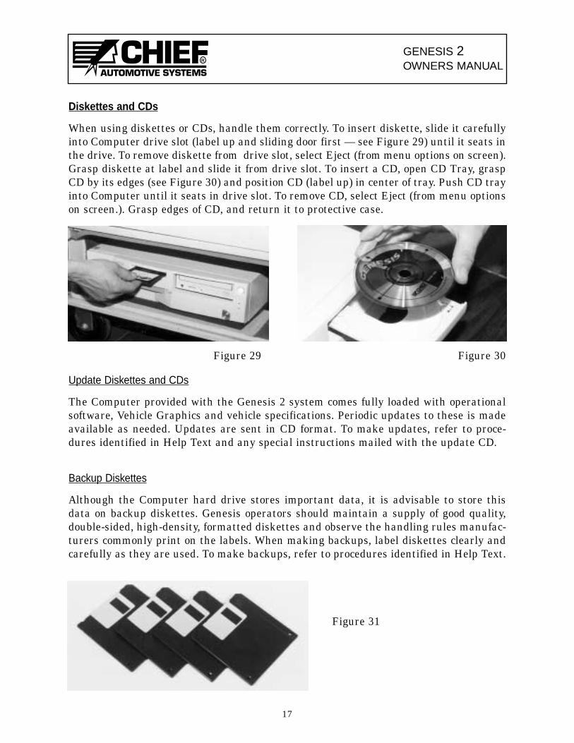
When using diskettes or CDs, handle them correctly. To insert diskette, slide it carefullyinto Computer drive slot (label up and sliding door first — see Figure 29) until it seats inthe drive. To remove diskette from drive slot, select Eject (from menu options on screen).Grasp diskette at label and slide it from drive slot. To insert a CD, open CD Tray, graspCD by its edges (see Figure 30) and position CD (label up) in center of tray. Push CD trayinto Computer until it seats in drive slot. To remove CD, select Eject (from menu optionson screen.). Grasp edges of CD, and return it to protective case.
Figure 29 Figure 30
Update Diskettes and CDs
The Computer provided with the Genesis 2 system comes fully loaded with operationalsoftware, Vehicle Graphics and vehicle specifications. Periodic updates to these is madeavailable as needed. Updates are sent in CD format. To make updates, refer to proce-dures identified in Help Text and any special instructions mailed with the update CD.
Backup Diskettes
Although the Computer hard drive stores important data, it is advisable to store thisdata on backup diskettes. Genesis operators should maintain a supply of good quality,double-sided, high-density, formatted diskettes and observe the handling rules manufac-turers commonly print on the labels. When making backups, label diskettes clearly andcarefully as they are used. To make backups, refer to procedures identified in Help Text.
Figure 31
17
COMPONENT MAINTENANCE(See also User’s Manuals For Computer And Printer)
Other than cleaning, factory maintenance by qualified technicians is required for all com-ponents. Be sure system’s power is ‘off’ while cleaning is performed. In dusty, or dirtyenvironments, periodic cleaning is necessary. Specific instructions for cleaning criticalcomponents are described below.
Wipe all parts clean using a lint-free, low-abrasion cloth using only an ammonia-basedglass cleaner. Never use solvents or alcohol-based cleaners of any kind on any part ofGenesis system.
Workstation Air Filters
After disconnecting Workstation power source, remove air filters and wash them in warmwater and a mild detergent. Shake off excess water, allow to dry, and reinstall.
Body Scanner Care
Do not plug or unplug cable from Body Scanner unless it is turned off.
Keep Body Scanner away from areas being undercoated, primed or painted. Keep heataway from Body Scanner when using a torch for thermal stress relieving of structuralcomponents.
Use only special tool kit provided to clean plastic lens on top of hub, filter lens on side ofhub, and Fresnell lens on plate directly above hub.
Clean all Body Scanner parts with a lint-free, low-abrasion cloth and a good quality glassor ammonia cleaner. Never use solvents or alcohol-based cleaners on Body Scanner lenses.
Care of Targets
Keep Targets away from areas being undercoated, primed or painted, and away fromheat when using a torch for thermal stress relieving of structural components.
Use a lint-free, low-abrasion cloth and a good quality glass or ammonia cleaner to cleanTargets. Do not use solvents.
Avoid scratching or gouging the Target’s reflective surface.
18
GENESIS 2OWNERS MANUAL
R
GENESIS 2OWNERS MANUAL
R
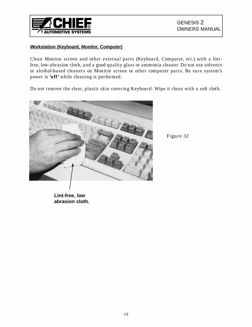
Workstation (Keyboard, Monitor, Computer)
Clean Monitor screen and other external parts (Keyboard, Computer, etc.) with a lint-free, low-abrasion cloth, and a good quality glass or ammonia cleaner. Do not use solventsor alcohol-based cleaners on Monitor screen or other computer parts. Be sure system’spower is ‘off’ while cleaning is performed.
Do not remove the clear, plastic skin covering Keyboard. Wipe it clean with a soft cloth.
19
Lint-free, lowabrasion cloth.
Figure 32
COMPONENT TROUBLESHOOTING
Genesis 2 computerized measuring system contains on-line troubleshooting assistancedesigned to identify and eliminate problems that arise when using the system. In mostinstances, troubleshooting problems are signaled by “Error Messages” that appear onscreen. Genesis 2 Help Text contains information and possible solutions for these “ErrorMessages”.
There are two methods of accessing troubleshooting assistance.
• Press F1 Key on Keyboard when “Error Message” appears. This method accesses a spe-cific Help Page immediately.
• Access Help Index by Menu selection or Tool Bar Icon. Then select Troubleshooting toaccess a specific menu. Each selection made in this process channels the operator to thehelp that’s desired.
Although “Error Messages” identify problems when Genesis 2 system is up and running,they obviously cannot identify problems when system is down. The following suggestionsare provided when system’s major components are not functioning. In addition to infor-mation listed here and in Genesis 2 Help Text, refer also to User’s Manuals for theComputer and Printer. If troubleshooting problem(s) can not be solved after reviewingthese sources of information, contact Chief Automotive Systems, Inc. for assistance. (SeePage 5 for instructions.)
No Power To System Components
Computer, Monitor, Keyboard, Mouse, Pen, Body Scanner, Printer
• Make sure Genesis 2 system is connected to a live 110-volt, 15 amp power source. A sin-gle purpose line for Genesis 2 is recommended. Do not use circuits subject to frequentinterruptions or outages. Also, avoid circuits with power surges such as from weldersand some power tools.IMPORTANT: Voltage requirements may vary in some countries.
• Check all electrical and cable connections (i.e. power source, back of Workstation, insideWorkstation, back of Computer, back of Printer, end of Body Scanner).
• Check fuses on back of Workstation and replace if blown.
• Inspect all electrical wiring and cable for damage or wear.
• Make sure ‘on’/’off ’ switches are in ‘on’ position (Computer, Body Scanner, Printer).
20
GENESIS 2OWNERS MANUAL
R

GENESIS 2OWNERS MANUAL
R
III. GENESIS 2 PROGRAM
STARTING UP GENESIS 2 SYSTEM
Turn system power switch ‘on’. (Figure 33 shows switch at rear of workstation.)
Computer will examine its circuits and prepare to run Genesis 2 system. This process iscalled ‘booting up the computer’. It takes several seconds to complete.
When Genesis 2 ‘Title Screen’ is displayed, ‘booting up’ procedure is complete. Genesis 2Main Menu Window will appear a few seconds after the Title Screen.
Figure 33
SHUTTING DOWN GENESIS 2 SYSTEM
To shut down Genesis 2 System, select Exit from list of items below File heading inGenesis 2 Main Menu Window. (See Figure 2.) This step accesses Program ManagerWindow. Then select Exit Windows from list of items under File heading. This accessesDialog Box which reads “This Will End Your Windows Session”. Select OK and then turnpower switch at back of workstation to ‘off ’.
21
Vehicle Options
Genesis 2
Update
Print Setup
Back Up
Restore
Import
Exit
File
Figure 34
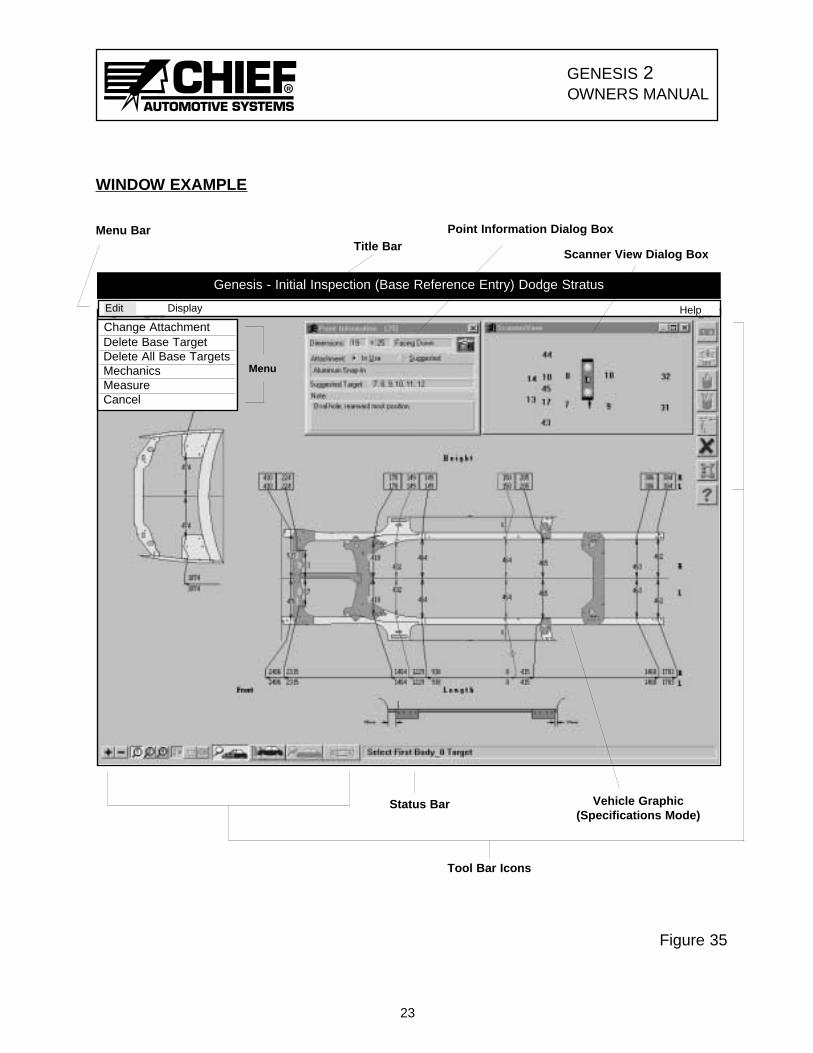
WINDOWS
Genesis 2 program is provided in a Windows software format that allows operators tomanage work easily and efficiently. All work applications appear on Windows which arebasically large rectangular areas on screen. Most Windows have certain elements in com-mon, for example: Title Bar, Menu Bar. Not all Windows, however, have every element.
In addition to elements that appear on a Window, there are other elements that appearalong right side or bottom edge of Window. Such elements vary from one Window toanother.
Figure 35 identifies some of the basic elements that appear either directly on Windowsor at the right side or bottom edge of Windows. Elements identified on the illustrationare described below. The illustration displayed is representative of a Repair Window withthe Zoom feature in use.
To work within a Window, operators have option of using Keyboard, Mouse, or Pendevices or a combination of any two or all three. Specific information on using thesedevices appears on Pages 28 through 32 and in Genesis on-line Help Text.
Title Bar — Identifies Window. (Located across top of Window.)
Menu Bar — Identifies Menu Headings. (Located across top of page belowTitle Bar.)
Menu Headings — Identifies menu lists that are available.
Menu List — Identifies tasks computer is ready to perform.
Scroll Bars — Used to expand Window when enlarged image of Vehicle Graphicexceeds display area.
Tool Bar Icons (Buttons) — Used to perform certain functions quickly. Graphic suggests
purpose or identity of function.
Status Bar — Systematically appears at bottom of Window to provide on-screen help throughout Genesis Program. Brief messages either instruct operator as to next course of action or describe purpose of menu selections or ToolBar Icons.
Dialog Box — Box that appears on Window for inputting, viewing or editing information.
Vehicle Graphic — Top view of vehicle’s substructure showing reference point locations, vehicle measurements, and direction of misalignment. (See additional information on Vehicle Graphics on Pages 26-27.)
22
GENESIS 2OWNERS MANUAL
R
R
GENESIS 2OWNERS MANUAL
Genesis - Initial Inspection (Base Reference Entry) Dodge Stratus
Title BarPoint Information Dialog Box
Scanner View Dialog Box
Tool Bar Icons
Vehicle Graphic(Specifications Mode)
Status Bar
Figure 35
23
Change AttachmentDelete Base TargetDelete All Base TargetsMechanicsMeasureCancel
Menu
WINDOW EXAMPLE
Menu Bar
DisplayEdit Help

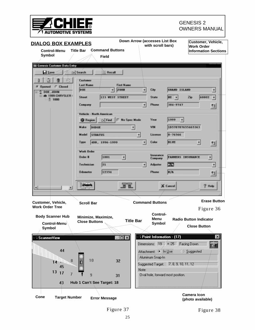
DIALOG BOXES
Dialog Boxes appear on a Window when operator must supply additional information tocomplete a task or when operatorn needs to access information. Most Dialog Boxesrequire selection of options, whereas others require inputting (typing) of information.
Most Dialog Boxes have elements in common, for example: Title Bars, CommandButtons, and Control-Menu Symbol Button. Not all Dialog Boxes have every element.
Figures 36-38 identify some of the different styles of Dialog Boxes and some of the dif-ferent elements within Dialog Boxes. Figure 36 shows a Customer Data Entry DialogBox; Figure 37 shows a Scanner View Dialog Box; and, Figure 38 shows a PointInformation Dialog Box. Elements that appear in these Dialog Boxes are described below.
To work within or move a Dialog Box, operators have may use Keyboard, Mouse, or Pendevices or a combination of any two or all three. Specific information on the use of thesedevices within Dialog Boxes appears on Pages 28-30 and in Genesis on-line Help Text.
Title Bar — Identifies Dialog Box. (Located across top of Dialog Box.)
Command Button — Used to perform certain functions quickly. Graphic suggests purpose or identity of function.
Field — Specific line for inputting, viewing, editing information.
Cursor — Operator controlled indicator that appears on Windows, Dialog Boxes, and Help Pages. Changes shape as per application.
List Box — Listing of choices that are available.
Close Button — Used to remove Dialog Box from Window. (Located in upper rightcorner of Dialog Box.)
Scroll Bars — Used to expand List Box when information exceeds display area.
Target Numbers — Numbers in Scanner View Dialog Box represent Targets mounted to vehicle and are displayed as per their positioning relative to Body Scanner.
Cone (Scanner View) — Identifies Target(s) not seen by Body Scanner.
Body Scanner — Graphic in Scanner View Dialog Box represents Body Scanner. Laser Hubs are identified as Hub 1 (on left side of vehicle) and Hub 2 (on right side of vehicle.)
Radio Button — Diamond-shaped indicator on Dialog Boxes that identifies component that is in use or is suggested.
Control-Menu _ Accesses Menu List for Restore, Move, Size, Mimimize, MaximizeSymbol and Close Functions.
24
GENESIS 2OWNERS MANUAL
R
GENESIS 2OWNERS MANUAL
R
25
DIALOG BOX EXAMPLES Customer, Vehicle,Work OrderInformation SectionsTitle Bar
Down Arrow (accesses List Box with scroll bars)
Field
Command ButtonsCustomer, Vehicle,Work Order Tree
Erase Button
Command Buttons
Title Bar
Camera Icon(photo available)
Radio Button Indicator
Cone
Hub 1 Can’t See Target: 18
Target Number Error Message
Body Scanner Hub
Close Button
Minimize, Maximize,Close Buttons
Figure 36
Figure 37 Figure 38
Control-MenuSymbol
Control-MenuSymbol
Control-MenuSymbol
Scroll Bar
GENESIS 2OWNERS MANUAL
R
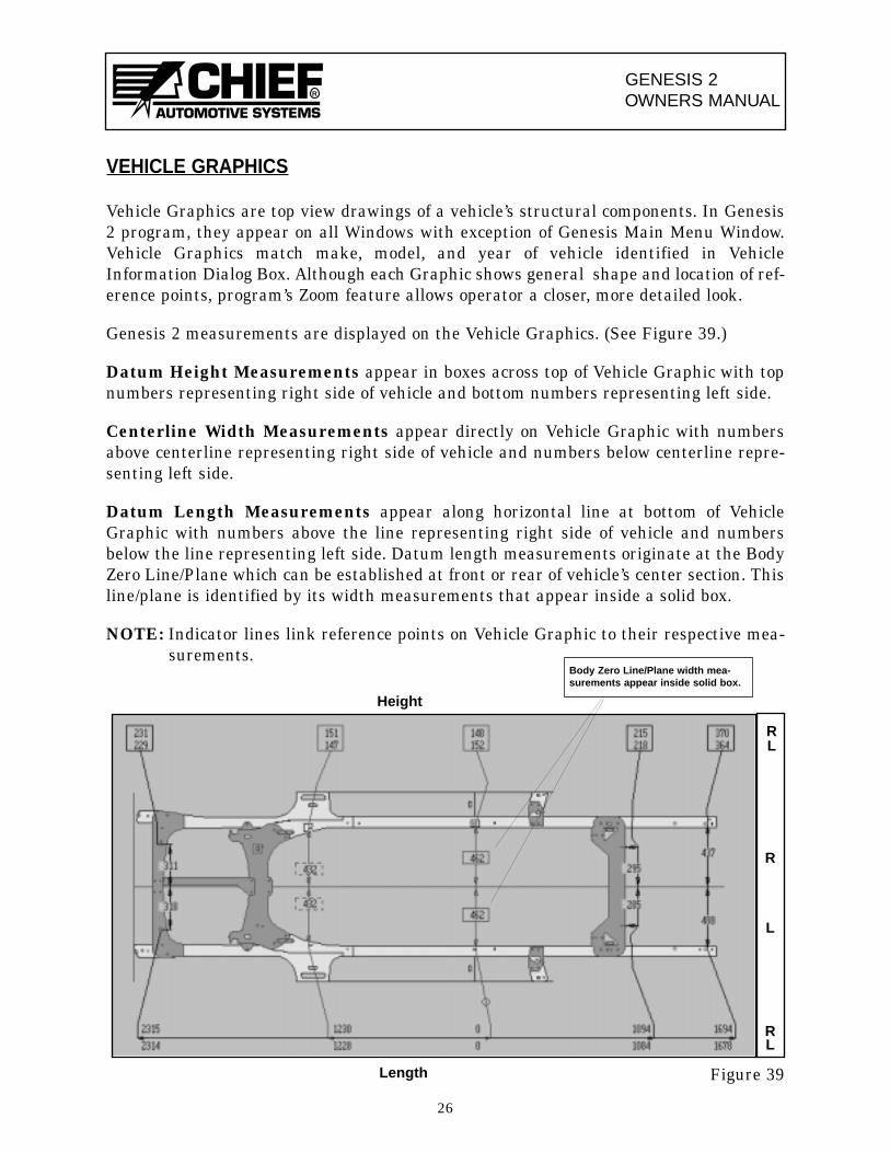
VEHICLE GRAPHICS
Vehicle Graphics are top view drawings of a vehicle’s structural components. In Genesis2 program, they appear on all Windows with exception of Genesis Main Menu Window.Vehicle Graphics match make, model, and year of vehicle identified in VehicleInformation Dialog Box. Although each Graphic shows general shape and location of ref-erence points, program’s Zoom feature allows operator a closer, more detailed look.
Genesis 2 measurements are displayed on the Vehicle Graphics. (See Figure 39.)
Datum Height Measurements appear in boxes across top of Vehicle Graphic with topnumbers representing right side of vehicle and bottom numbers representing left side.
Centerline Width Measurements appear directly on Vehicle Graphic with numbersabove centerline representing right side of vehicle and numbers below centerline repre-senting left side.
Datum Length Measurements appear along horizontal line at bottom of VehicleGraphic with numbers above the line representing right side of vehicle and numbersbelow the line representing left side. Datum length measurements originate at the BodyZero Line/Plane which can be established at front or rear of vehicle’s center section. Thisline/plane is identified by its width measurements that appear inside a solid box.
NOTE: Indicator lines link reference points on Vehicle Graphic to their respective mea-surements.
Figure 39
26
Body Zero Line/Plane width mea-surements appear inside solid box.
R
L
RL
RL
Height
Length
GENESIS 2OWNERS MANUAL
R
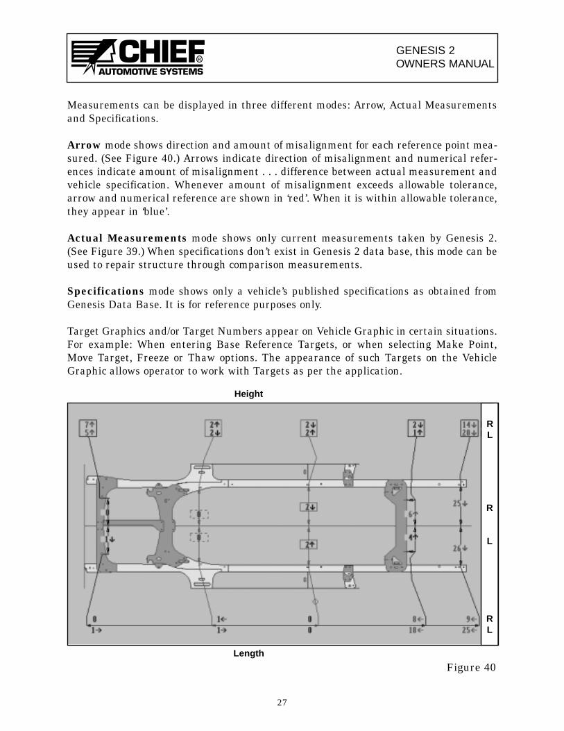
Measurements can be displayed in three different modes: Arrow, Actual Measurementsand Specifications.
Arrow mode shows direction and amount of misalignment for each reference point mea-sured. (See Figure 40.) Arrows indicate direction of misalignment and numerical refer-ences indicate amount of misalignment . . . difference between actual measurement andvehicle specification. Whenever amount of misalignment exceeds allowable tolerance,arrow and numerical reference are shown in ‘red’. When it is within allowable tolerance,they appear in ‘blue’.
Actual Measurements mode shows only current measurements taken by Genesis 2.(See Figure 39.) When specifications don’t exist in Genesis 2 data base, this mode can beused to repair structure through comparison measurements.
Specifications mode shows only a vehicle’s published specifications as obtained fromGenesis Data Base. It is for reference purposes only.
Target Graphics and/or Target Numbers appear on Vehicle Graphic in certain situations.For example: When entering Base Reference Targets, or when selecting Make Point,Move Target, Freeze or Thaw options. The appearance of such Targets on the VehicleGraphic allows operator to work with Targets as per the application.
27
R
L
RL
RL
Height
Length
Figure 40
GENESIS 2OWNERS MANUAL
R
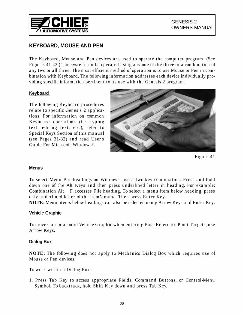
KEYBOARD, MOUSE AND PEN
The Keyboard, Mouse and Pen devices are used to operate the computer program. (SeeFigures 41-43.) The system can be operated using any one of the three or a combination ofany two or all three. The most efficient method of operation is to use Mouse or Pen in com-bination with Keyboard. The following information addresses each device individually pro-viding specific information pertinent to its use with the Genesis 2 program.
Keyboard
Figure 41
Menus
To select Menu Bar headings on Windows, use a two key combination. Press and holddown one of the Alt Keys and then press underlined letter in heading. For example:Combination Alt + F accesses File heading. To select a menu item below heading, pressonly underlined letter of the item’s name. Then press Enter Key.NOTE: Menu items below headings can also be selected using Arrow Keys and Enter Key.
Vehicle Graphic
To move Cursor around Vehicle Graphic when entering Base Reference Point Targets, useArrow Keys.
Dialog Box
NOTE: The following does not apply to Mechanics Dialog Box which requires use ofMouse or Pen devices.
To work within a Dialog Box:
1. Press Tab Key to access appropriate Fields, Command Buttons, or Control-MenuSymbol. To backtrack, hold Shift Key down and press Tab Key.
28
The following Keyboard proceduresrelate to specific Genesis 2 applica-tions. For information on commonKeyboard operations (i.e. typingtext, editing text, etc.), refer toSpecial Keys Section of this manual(see Pages 31-32) and read User’sGuide For Microsoft Windows®.
GENESIS 2OWNERS MANUAL
R
2. Type information in appropriate Fields or scroll for it when List Boxes appear. ArrowKeys scroll one item at a time and Page Up and Page Down Keys scroll one group ofitems at a time.
3. Select appropriate Command Button and press Enter Key.
4. In some Dialog Boxes, move indicators using a two key combination. Press and holdone of the Alt Keys and then press underlined letter of the selection.
IMPORTANT: When working in a Dialog Box, DO NOT press Enter Key until perti-nent information has been inputted and appropriate CommandButton has been selected.
To Move, Close, And/Or Activate:
1. To move a Dialog Box using Keyboard, press Alt + Space Bar. Then select Move frommenu and press Enter Key. Use Arrow Keys to move Dialog Box to appropriate loca-tion and then press Enter Key again.
2. To close a Dialog Box using Keyboard, access Control-Menu Symbol (upper left corner)and press Enter Key. Then use Arrow Keys to select Close and press Enter Key again.
3. When two Dialog Boxes are displayed at same time, only one will be activated. To acti-vate the other, press Alt + F6 Key. Title Bar of activated Dialog Box will appear high-lighted.
Genesis 2 Help Pages
1. To access Help Index, press F1 Key upon accessing Genesis 2 Main Menu Window orselect Index from list of items under Help heading in any Menu Bar.
2. To access specific Help about information displayed (i.e. highlighted Menu items,Dialog Boxes, Vehicle Graphics, Status Bar Messages, Error Messages, etc.), press F1Key. NOTE: In regard to Dialog Boxes, specific Help can also be accessed by selecting
which appears in most Dialog Boxes.
How To Use Help
To access How To Use Help, first access any Genesis 2 Help Page. Then press F1 Key orselect How To Use Help from list of items under Help heading in Menu Bar.
29
?Help
GENESIS 2OWNERS MANUAL
R
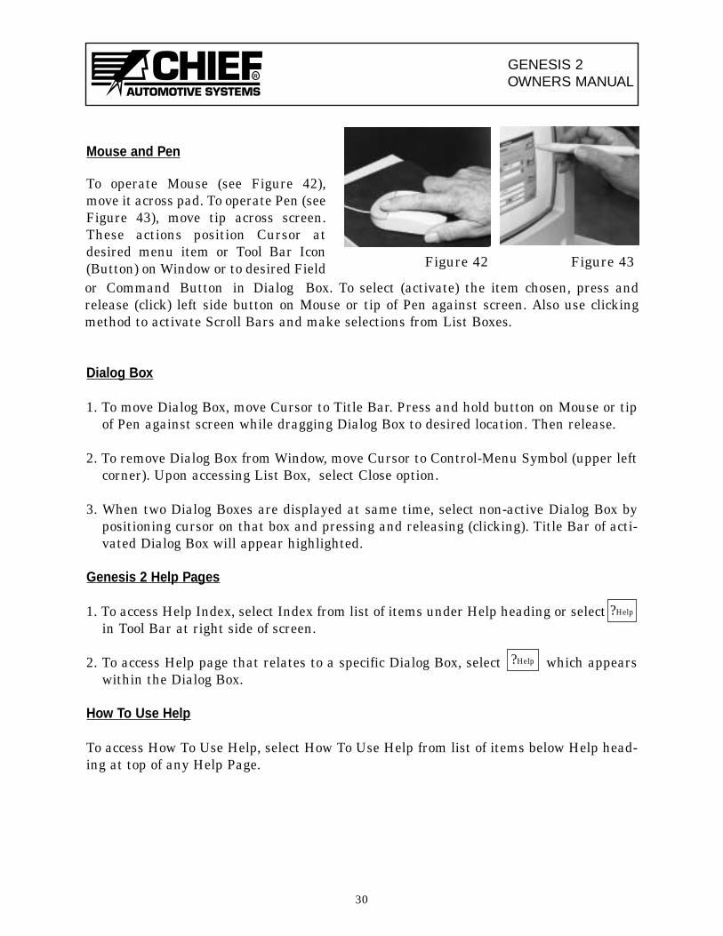
Mouse and Pen
Dialog Box
1. To move Dialog Box, move Cursor to Title Bar. Press and hold button on Mouse or tipof Pen against screen while dragging Dialog Box to desired location. Then release.
2. To remove Dialog Box from Window, move Cursor to Control-Menu Symbol (upper leftcorner). Upon accessing List Box, select Close option.
3. When two Dialog Boxes are displayed at same time, select non-active Dialog Box bypositioning cursor on that box and pressing and releasing (clicking). Title Bar of acti-vated Dialog Box will appear highlighted.
Genesis 2 Help Pages
1. To access Help Index, select Index from list of items under Help heading or selectin Tool Bar at right side of screen.
2. To access Help page that relates to a specific Dialog Box, select which appearswithin the Dialog Box.
How To Use Help
To access How To Use Help, select How To Use Help from list of items below Help head-ing at top of any Help Page.
30
or Command Button in Dialog Box. To select (activate) the item chosen, press andrelease (click) left side button on Mouse or tip of Pen against screen. Also use clickingmethod to activate Scroll Bars and make selections from List Boxes.
?Help
?Help
To operate Mouse (see Figure 42),move it across pad. To operate Pen (seeFigure 43), move tip across screen.These actions position Cursor atdesired menu item or Tool Bar Icon(Button) on Window or to desired Field Figure 42 Figure 43
GENESIS 2OWNERS MANUAL
R
SPECIAL KEYS
As previously indicated, Genesis 2 program can be operated using any one of the threedevices or a combination of any two or all three.
When using Keyboard either solely or in combination with other devices, operators willuse not only the ‘letter’ and ‘number’ keys but the specialty keys as well. Many of thesekeys provide a more convenient method for moving around in Windows, Dialog Boxes andHelp Pages.
Following is a listing of special keys that are used in Genesis 2 Program.
Alt (alternate key) — Two key combination involving Alt Key + another key.
Arrow Keys — Used to move Cursor up or down and right or left, also moveshighlighted Cursor in some applications.
Backspace Key — Moves Cursor backwards to erase last character.
Control Key — Two key combination involving Ctrl Key + another key.
Delete Key — Removes one character to right of Cursor or all highlighted areas.
End Key — Moves Cursor to end of field.
Enter Key — Used in Keyboard operation only. Used to select items from menus, close Dialog Boxes, access other Dialog Boxes, enter Targets on Vehicle Graphic, select Command Buttons, dispose of Help Pop-ups. Serves same function as Mouse button and tip ofPen.
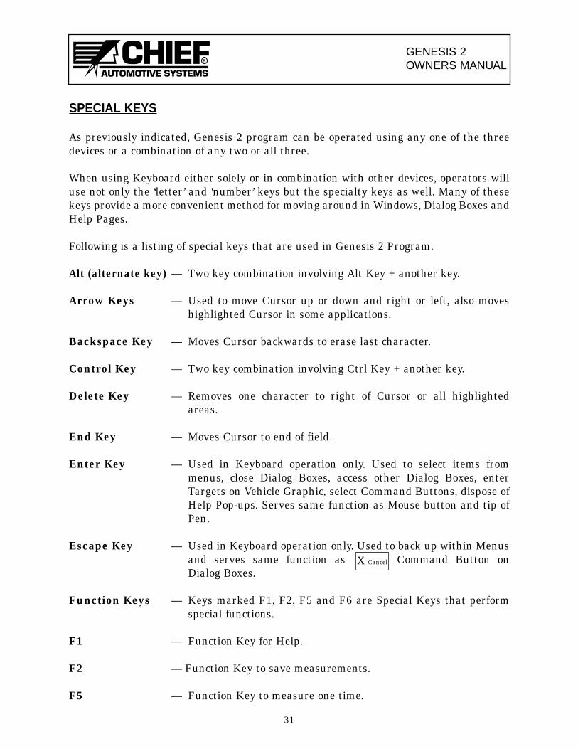
Escape Key — Used in Keyboard operation only. Used to back up within Menus and serves same function as Command Button on Dialog Boxes.
Function Keys — Keys marked F1, F2, F5 and F6 are Special Keys that perform special functions.
F1 — Function Key for Help.
F2 — Function Key to save measurements.
F5 — Function Key to measure one time.
31
X Cancel
F6 — Function Key to start or stop continuous measuring.
Home Key — Moves Cursor to beginning of field.
Insert Key — Inserts text without erasing other text.
Num Lock Key — On/Off Key for cluster of number keys on lower right side of Keyboard.
Number Keys — Two sets of Number Keys available on Keyboard.
Page Down Key — Used for scrolling downward through page when text extendsbeyond Window.
Page Up Key — Used for scrolling upward through page when text extends beyond Window.
Print Screen Key — Command Key for printing current Genesis 2 Window.
Shift Key — Serves same function as typewriter shift key.
Tab Key — Used to move around in Help and in Dialog Box.
Typewriter Keys — Same as typewriter.
32
GENESIS 2OWNERS MANUAL
R

GENESIS 2 WINDOWS AND MENUS
The Genesis 2 software program utilizes five Windows: Main Menu Window; InitialInspection Window; Repair Window; Final Inspection Window; and, Recall Window.The Windows feature Menu Bars which identify operations or commands that areavailable for that Window. (See Genesis 2 Basic Training Manual.)
Menu selections appearing below Menu Bar headings identify tasks system is ready toperform. To make selections, operators have option of using Keyboard, Mouse or Pendevices or a combination of any two or all three. Specific information on using thesedevices is covered on Pages 28 through 32 of this manual and in Genesis 2 on-line HelpText.
IMPORTANT:
• Refer to Genesis 2 on-line Help Text for a more detailed description of menu selectionsand for related procedural information. For information on How To Use Help, see HowTo Use Help on Pages 36-39 or access the on-line How To Use Help System. Refer alsoto User’s Guide for Microsoft Windows.
• Menu selections that appear dimmed are inaccessible.
• Tool Bar Icons (Buttons) provide a faster way to perform tasks than the menu selec-tion method. See Tool Bar Icons (Buttons) in Genesis 2 Basic Training Manual.
33
GENESIS 2OWNERS MANUAL
R
GENESIS 2OWNERS MANUAL
R
HELP TEXT
The On-Line Help Text provides assistance on practically all aspects of Genesis 2 com-puterized measuring system. Information ranges from installation of hardware compo-nents to software utilization.
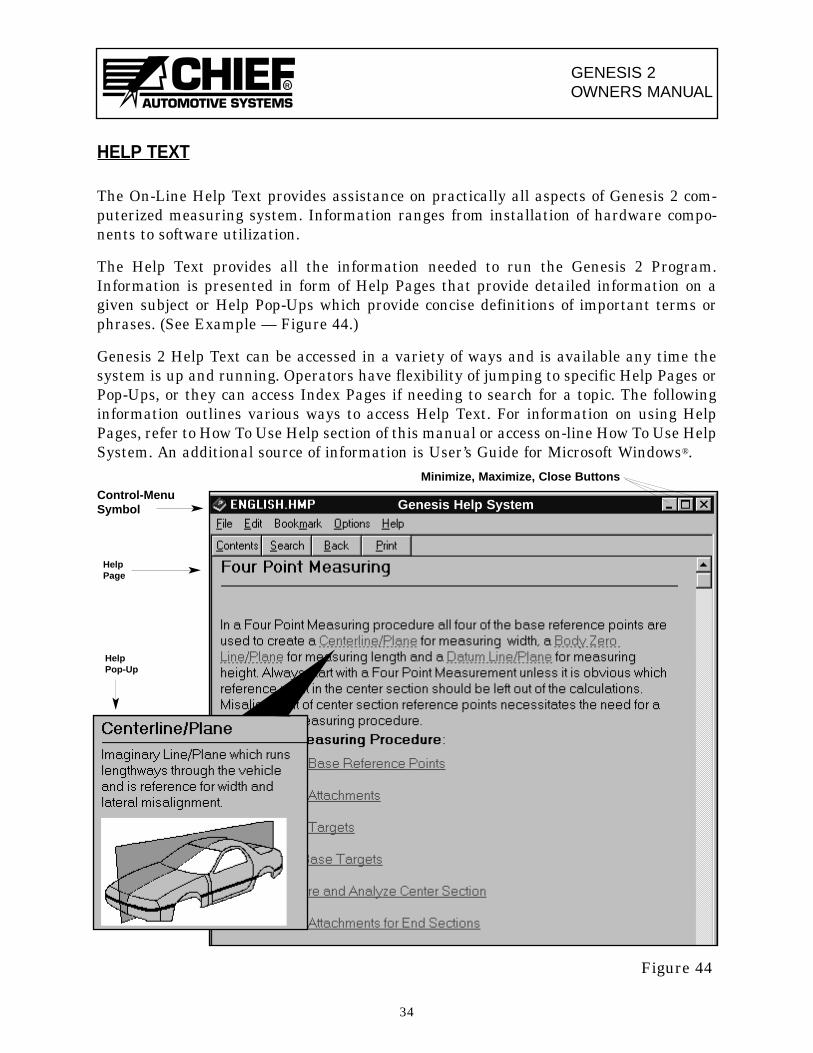
The Help Text provides all the information needed to run the Genesis 2 Program.Information is presented in form of Help Pages that provide detailed information on agiven subject or Help Pop-Ups which provide concise definitions of important terms orphrases. (See Example — Figure 44.)
Genesis 2 Help Text can be accessed in a variety of ways and is available any time thesystem is up and running. Operators have flexibility of jumping to specific Help Pages orPop-Ups, or they can access Index Pages if needing to search for a topic. The followinginformation outlines various ways to access Help Text. For information on using HelpPages, refer to How To Use Help section of this manual or access on-line How To Use HelpSystem. An additional source of information is User’s Guide for Microsoft Windows®.
34
HelpPop-Up
HelpPage
Genesis Help System
Figure 44
Minimize, Maximize, Close Buttons
Control-MenuSymbol
GENESIS 2OWNERS MANUAL
R
To Access Specific Help From Window Or Dialog Box
IMPORTANT: See Keyboard/Mouse/Pen on Pages 28-32 for information on movingaround (and making selections) in Windows and Dialog Boxes. See HowTo Use Help on Pages 36-39 for information on obtaining additional helpafter accessing a Help Page.
• Highlight specific menu item and press F1 Key.• Select (Command Button) in active Dialog Box or press F1 Key when active
Dialog Box appears on Window.• When there are no active Dialog Boxes on Window, press F1 Key to access definitions
for that Window’s Menus and Tool Bar Icons. The lone exception is when Title Bar ofWindow indicates Base Reference Entry. The F1 Key then accesses Base ReferenceEntry procedures. From this procedures page, operator has option to access definitionsfor Base Reference Entry Menus and Tool Bar Icons.NOTE: 1. Dialog Boxes are active when Title Bars are highlighted.
2. When an active Dialog Box appears, remove it from Window prior to pressing F1 Key.
• To access Help Index, select Index from list of items under Help heading or select(Help Icon) from Tool Bar.
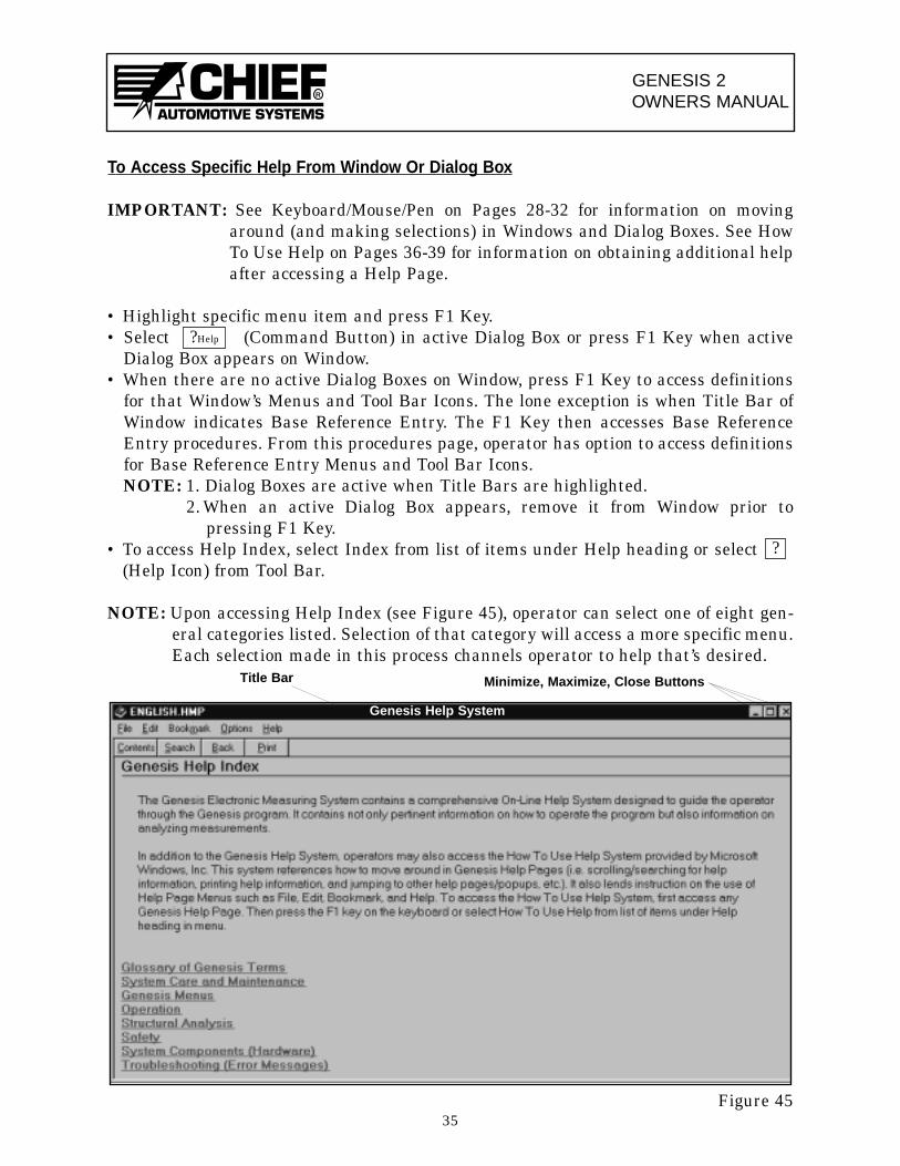
NOTE: Upon accessing Help Index (see Figure 45), operator can select one of eight gen-eral categories listed. Selection of that category will access a more specific menu.Each selection made in this process channels operator to help that’s desired.
Figure 4535
?Help
?
Genesis Help System
Minimize, Maximize, Close ButtonsTitle Bar
GENESIS 2OWNERS MANUAL
R
HOW TO USE HELP
NOTE: In addition to the following information on How To Use Help, refer to on-lineHow To Use Help System and User’s Guide for Microsoft Windows®.
Upon accessing a specific Help Page or Index Page, operators can easily move through-out Help Text to access additional information as needed. As noted in Help Text infor-mation on Pages 34-35 , the basic way to do this is by jumping from one Help Page toanother Help Page or to a Help Pop-Up.
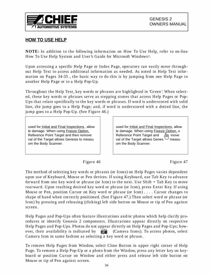
Throughout the Help Text, key words or phrases are highlighted in ‘Green’. When select-ed, these key words or phrases serve as stepping stones that access Help Pages or Pop-Ups that relate specifically to the key words or phrases. If word is underscored with solidline, the jump goes to a Help Page; and, if word is underscored with a dotted line, thejump goes to a Help Pop-Up. (See Figure 46.)
Figure 46 Figure 47
The method of selecting key words or phrases (or Icons) on Help Pages varies dependentupon use of Keyboard, Mouse or Pen devices. If using Keyboard, use Tab Key to advanceforward from one key word or phrase (or Icon) to the next. Use Shift + Tab Key to moverearward. Upon reaching desired key word or phrase (or Icon), press Enter Key. If usingMouse or Pen, position Cursor on Key word or phrase (or Icon) . . . . Cursor changes toshape of hand when correctly positioned. (See Figure 47.) Then select word or phrase (orIcon) by pressing and releasing (clicking) left side button on Mouse or tip of Pen againstscreen.
Help Pages and Pop-Ups often feature illustrations and/or photos which help clarify pro-cedures or identify Genesis 2 components. Illustrations appear directly on respectiveHelp Pages and Pop-Ups. Photos do not appear directly on Help Pages and Pop-Ups; how-ever, their availability is indicated by (Camera Icons). To access photos, selectCamera Icon in same fashion as selecting a key word or phrase.
To remove Help Pages from Window, select Close Button in upper right corner of HelpPage. To remove a Help Pop-Up or a photo from the Window, press any letter key on key-board or position Cursor on Window and either press and release left side button onMouse or tip of Pen against screen.
36
used for Initial and Final Inspections , allowle damage. When using Freeze Option,Reference Point Target and then removeval of the Target allows Genesis to measuom the Body Scanner.
used for Initial and Final Inspections, allowle damage. When using Freeze Option, oReference Point Target and moveval of the Target allows Genes measuom the Body Scanner.

GENESIS 2OWNERS MANUAL
R
Help Page Features
Each Help Page in Genesis 2 Help Text has certain elements in common. These include aMenu Bar, Command Buttons, Scroll Bars, Minimize and Maximize options and a Closeoption. (See Example — Figure 48.) Scroll Bars exist on some of pages.
Menu Bar allows operators to access File, Edit, Bookmark, Options and Help Functions.Command Buttons allow operator to access information quickly. Minimize and Maximizefeatures enlarge and reduce Help Page and Close option removes it from Window. ScrollBars allow access to information that does not fit on Window.
Minimize and Maximize options allow only limited sizing of Help Page. Using Mouse orPen, position Cursor at vertical or horizontal border or at corner of Help Page . . . Cursorwill change to shape of double arrow. Press and hold down left side button on Mouse ortip of Pen against screen. Drag Cursor to enlarge or reduce Help Page and then release.
Using Keyboard, press Alt + Space Bar to access menu list below Control-Menu Symbolat left side of Title Bar. Using Arrow Keys, select Size and press Enter Key. Move Cursor(using Arrow Keys) to vertical or horizontal border or to corner of Help Page. Continueusing Arrow Keys to size the Help Page. When sized correctly, press Enter Key.
37
Genesis Help System Title Bar
Menu BarCommandButtons
ScrollBars
HelpPageTitle
Figure 48
Genesis Help System
ControlMenuSymbol(accessesMimimize,Maximize,Close,options)
GENESIS 2OWNERS MANUAL
R
Help Page Command Buttons
Command Button accesses Genesis Help Index.
Command Button accesses Dialog Box that allows operator to do an alphabetical search for desired Help Topic.
Command Button allows operator to return to previously displayed Help Page.
Command Button accesses Dialog Box that allows operator to print theGenesis 2 Help page displayed.
NOTE: When accessing on-line How To Use Help System, a Command Buttonappears with and Command Buttons.Selection of Button accesses a listing of common terms used inWindows Program. Selection of a term from listing accesses its definition. Toaccess on-line How To Use Help System, first access a Genesis Help Page and doone of the following: Select How To Use Help from list of items under Help head-ing; or, press F1 Key.
Control-Menu Symbol
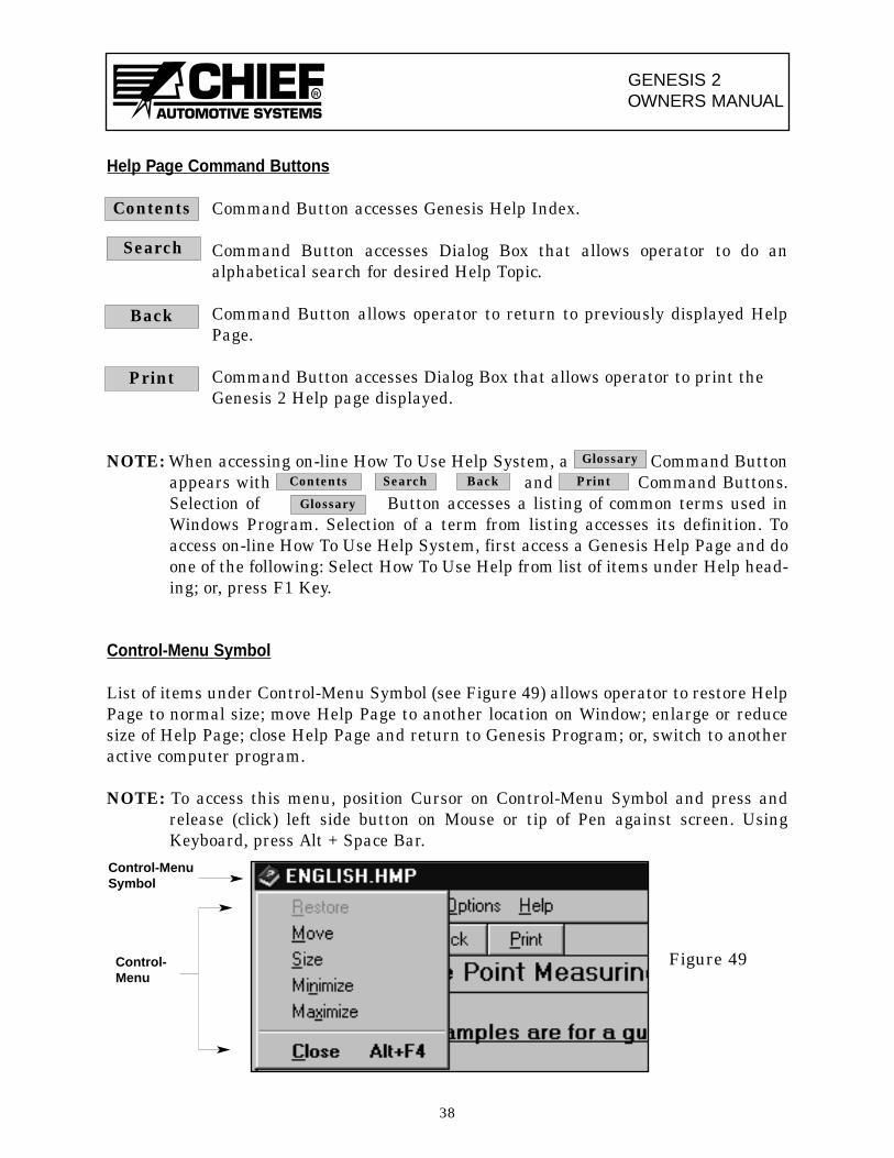
List of items under Control-Menu Symbol (see Figure 49) allows operator to restore HelpPage to normal size; move Help Page to another location on Window; enlarge or reducesize of Help Page; close Help Page and return to Genesis Program; or, switch to anotheractive computer program.
NOTE: To access this menu, position Cursor on Control-Menu Symbol and press andrelease (click) left side button on Mouse or tip of Pen against screen. UsingKeyboard, press Alt + Space Bar.
38
Contents
Search
Back
Glossary
Contents Search Back Print
Glossary
Figure 49Control-Menu
Control-MenuSymbol

R
Form G 2 OM (Rev. 5/99)Part No. 798510
Chief reserves the right to alter product specifications and/orpackage components without notice.
P.O. Box 1368Grand Island, Nebraska 68802-1368Phone 308-384-9747Fax 308-384-8966
INTAIRCO S.A.R.L.CA de TREMBLAY CHARLES DE GAULLE18, rue Henri FARMAN93297 TREMBLAY EN FRANCE CEDEXTEL 01 41 51 16 80FAX 01 48 60 09 88

![Genesis 1 2 [ ] Genesis 2-3 3 [ ] J AN UAR Y...J A N U A R Y 1 [_] Genesis 1 2 [_] Genesis 2-3 3 [_] Genesis 4-5 4 [_] Genesis 6-7 5 [_] Genesis 8-9 6 [_] Genesis 10-11 7 [_] Genesis](https://static.fdocuments.in/doc/165x107/60739b02ef6edb568a6ea6ad/genesis-1-2-genesis-2-3-3-j-an-uar-y-j-a-n-u-a-r-y-1-genesis-1-2.jpg)