Generic Verification Protocol for Vortex Separation … Verification Protocol for Vortex...
42
-
Upload
trinhthien -
Category
Documents
-
view
233 -
download
1
Transcript of Generic Verification Protocol for Vortex Separation … Verification Protocol for Vortex...

Generic Verification Protocol for Vortex Separation-DRAFT 4.2
ACKNOWLEDGEMENTS AND PREFACE
The USEPA and NSF International would like to acknowledge those persons who participated in the preparation, review and approval of this Protocol. Without their hard work and dedication to the project, this document would not have been approved through the process which has been set forth for this ETV project.
Generic Verification Protocol for Vortex Separation
Writer:
George Zukovs –XCG Consultants Ltd.
Reviewers:
John LaGorga and Dan Davis-Moffa & Associates
Technology Panel Members
Ms. Meei-Lih Ahmad
Mr. Mervyn Bowen
Mr. Richard Field
Mr. Stephen Hides
Ms. Mary Stinson
Mr. Philippe Topalian
Mr. Randy West
Mr. Peter Young
Mr. Jim Zaccagnino
Mr. George Zukovs
iii

Generic Verification Protocol for Vortex Separation-DRAFT 4.2
GLOSSARY OF TERMS (to be updated in final version)
Accuracy - a measure of the closeness of an individual measurement or the average of a number of measurements to the true value and includes random error and systematic error.
Bias - the systematic or persistent distortion of a measurement process that causes errors in one direction.
Comparability – a qualitative term that expresses confidence that two data sets can contribute to a common analysis and interpolation.
Core Parameter – a water quality parameter used to define test equipment performance. Core parameters shall be used at all testing sites and represent the minimum required.
EPA - the United States Environmental Protection Agency, its staff or authorized representatives
Field Testing Organization – An organization qualified to conduct verification testing of high-rate vortex separation technologies in accordance with protocols established under the Wet Weather Flow Technologies Pilot..
Manufacturer –a business that assembles or sells vortex separation technology equipment.
NSF – NSF International, its staff, or other authorized representatives.
Owner-a municipality, industry or other entity that would own and operate a full scale vortex separation facility.
Precision - a measure of the agreement between replicate measurements of the same property made under similar conditions.
Protocol – a written document that clearly states the objectives, goals, and scope of the study as well as the test plan(s) for the conduct of the study. A protocol shall be used for reference during Manufacturer participation in the verification testing program.
Representativeness - a measure of the degree to which data accurately and precisely represent a characteristic of a population parameter at a sampling point or for a process conditions or environmental condition.
iv
Generic Verification Protocol for Vortex Separation-DRAFT 4.2
Standard Operating Procedure – a written document containing specific procedures and protocols to ensure that quality assurance requirements are maintained.
Quality Assurance Project Plan – a written document that describes the implementation of quality assurance and quality control activities during the life cycle of the project.
Test Plan – A written document that establishes the detailed test procedures for verifying the performance of a specific technology. It also defines the roles of the specific parties involved in the testing and contains instructions for sample and data collection, sample handling and preservation, and quality assurance and quality control requirements relevant to a given test site.
Treatability Parameter- a water quality parameter used to define testing conditions or maximum removal efficiency
Verification – A process to establish the evidence on the range of performance of equipment and/or device such as a chemically-enhanced high-rate separator under specific conditions following a predetermined study protocol(s) and test plan(s).
Verification Report – a written document prepared by the FTO containing all raw and analyzed data, all QA/QC data sheets, descriptions of all collected data, a detailed description of all procedures and methods used in the verification testing, and all QA/QC results. The Test Plan(s) shall be included as part of this document.
Verification Statement –a written document that summarizes a final report reviewed and approved by NSF on behalf of EPA or directly by EPA.
v
Generic Verification Protocol for Vortex Separation-DRAFT 4.2
1. INTRODUCTION
This document contains the generic protocol to be employed for the verification testing of vortex separation equipment used for the treatment of combined sewer overflows (CSOs). The protocol has been prepared under the Environmental Technologies Verification (ETV) program.
The goal of verification testing is to provide objective information to manufacturers, owners, and staff of regulatory agencies regarding technology performance. Verification testing results in the issuance of a Verification Report documenting the the procedures and outcomes of a Site Specific Test and the issuance of a Verification Statement summarizing the site specific testing. More information about the ETV program can be found on the Internet at http://www.epa.gov/etv,or http://www.nsf.org/etv.
1.1 The Environmental Technologies Verification Program
The purpose of the ETV Program is three fold. Specifically, the program is intended to:
1. Evaluate the performance of innovative and commercially available environmental technologies;
2. Provide objective information about technology performance to permit writers, buyers and users, among others; and,
3. Facilitate “real world” implementation of promising technologies.
The ETV Program is subdivided into twelve individual pilot projects, one of which is the Wet Weather Flow (WWF) Technologies Pilot concerned with technologies appropriate for the treatment of wet weather flows, among other issues.
The verification testing process established by the United States Environmental Protection Agency (EPA) and the National Sanitation Foundation (NSF), is intended to serve as a template for conducting verification tests for various wet weather flow technologies. The goal of the verification testing process is to generate high quality data for verification of equipment performance.
The verification testing of vortex separation equipment is being overseen by NSF International with the participation of manufacturers, under the sponsorship of the EPA Office of Research and Development, with oversight by National Risk Management Research Laboratory’s Urban Watershed Management Branch (Edison, NJ) ,). NSF’s role is to provide technical and administrative leadership in conducting the testing. It is important to note that verification of the equipment does not mean that the equipment is “certified” by NSF or EPA. Instead, the verification testing pilot projects are a formal mechanism by which the performance of equipment can be determined by these two organizations.
1-1
Generic Verification Protocol for Vortex Separation-DRAFT 4.2
1.2 Verification Testing Process
The verification testing process consists of three phases as shown in Figure 1.1. They include:
Planning – The planning phase involves a number of characterization activities culminating in the preparation of a site specific Test Plan.
1-2

Generic Verification Protocol for Vortex Separation-DRAFT 4.2
POL
ICY
ET
V P
RO
GR
AM
VE
RIF
ICA
TIO
N T
EST
ING SOPs Technical
Assessments
Site Specific Test Plan
QA Project Plan
Data Assessment
Verification Reporting
Defensible Verification Statement
¤ Consensus Standards(ANSI/ ASQC E4) ¤ EPA Policies
¤ ETV Quality Management Plan (QMP) ¤ Wet Weather Flow Technologies QMP
¤ Site characterization ¤ Influent Characterization ¤ Experimental Design
¤ Verification Testing
¤ Data Assessment ¤ Verification
Reporting
PLANNING
Conduct Study/ Experiment
VERIFICATION DATA ASSESSMENT &
REPORTING
Figure 1.1 Verification Testing Process
1-3
Generic Verification Protocol for Vortex Separation-DRAFT 4.2
Verification Testing – This phase includes the actual verification testing activities.
Data Assessment and Reporting – This last phase includes all data analysis and verification steps as well as Verification Report preparation.
Figure 1.1 also shows the relationship of the verification testing process to higher level quality management plans (QMPs), EPA policies and consensus standards such as ANSI/ASQC E4.
1.3 Purpose and Scope of Protocol
This document contains guidance to Field Testing Organizations (FTOs), Manufacturers and Owners for verification testing of vortex separation facilities. Instructions are provided for preparation of Test Plans, execution of testing, data reduction and analysis, and reporting..
1.4 Vortex Separation Vortex separation devices are a class of physical treatment technology that employ the use of cylindrical chambers to induce rotational forces that separate settleable solids and associated pollutants. The vortex action concentrates solids into an underflow stream or underflow sump, thereby removing the solids and associated pollutants from the effluent stream.
Vortex separation devices have essentially no moving parts and rely on the inertial forces induced by the flow-path to collect and remove the concentrated pollutants. In some cases, the design of the device allows for the capture of floatable material.
The operation of a vortex separation device is as follows:
• Flow enters the unit through an inlet pipe and begins to fill the vortex separator unit,
• Solid-liquid separation is effected through the development of a vortex. The vortex action concentrates the solid particles in the underflow. Solid liquid separation is achieved due to differences in inertia between solid particles and the liquid and gravitational forces on the solid particles.
• The underflow or concentrated flow, containing the separated solid particles, exits through the base of the unit. The underflow is routed to a wastewater treatment facility for final treatment, or may be retained in an integral sump for removal at a later time.
• Some configurations include gross solids (floatables/aesthetic pollutants) capture mechanisms and are able to route the captured material to a wastewater treatment facility for final treatment;
• Overflow, containing the clarified liquid, discharges over a weir and is routed to a receiving water.
1-4
Generic Verification Protocol for Vortex Separation-DRAFT 4.2
• At the end of the storm event, the storm related influent first declines to less than the underflow rate. The storm event ends resulting in an end to the influent to the unit. When the water level in the unit begins to drop below the level of the overflow weir, the unit no longer overflows. Underflows continue until the vortex separator unit is completely empty. The separator may then be cleaned in anticipation of the next storm event.
1.5 Considerations in Verification Testing
1.5.1 Range of Testing
Ideally, the verification testing of vortex separation devices should occur under a wide range of storm and corresponding influent quantity and quality conditions. The test equipment should also be operated for each verification test through a full operating cycle. Verification testing under these conditions is the least constrained and therefore produces the most meaningful Verification Statement.
1.5.2 Performance Indicators and Quality Parameters
The performance evaluation of vortex separation devices is based on the assessment through site specific testing of the following:
• Treatment performance measured by test equipment effluent concentrations and test equipment removal efficiencies for selected water quality parameters.
• Operations and maintenance performance measured by a number of quantitative and qualitative O&M indicators including use of consumables (i.e., water and power), labor requirements, ease of operation among other factors.
The water quality parameters used to assess treatment performance include two categories or groups of parameters as follows (see Section 2.4):
• Core parameters which are water quality parameters used in all verification testing. The core parameter list is the minimum required for testing purposes.
• Supplemental parameters which are water quality parameters additional to the core parameters selected for a particular test site. Supplemental parameters are selected by the FTO in conjunction with the Manufacturer and Owner.
In addition to the core and supplemental parameters used to evaluate test unit treatment performance, verification testing will require measurement of other parameters termed treatability parameters at various stages of the testing process. Treatability parameters include water quality parameters such as settling velocity distribution (SVD) that help define the maximum removal efficiency of the test unit.
Details of performance indicators and quality parameters are presented in Section 2.0 of this protocol.
1-5

Generic Verification Protocol for Vortex Separation-DRAFT 4.2
2. PLANNING
2.1 Development of the Test Plan
The FTO shall prepare a Test Plan specific to each location where testing is proposed. The Test Plan shall be prepared in consultation with the facility Owner and equipment Manufacturer, and shall be reviewed by NSF prior to implementation. This Protocol provides guidelines for developing the Test Plan.
The specific contents of the Test Plan will vary from site to site; however, at a minimum, the Test Plan shall address the following elements:
• Scope and Purpose of Verification Test
• Roles and responsibilities of Verification Testing Participants
• Site Characteristics
• Influent Characteristics
• Technology Description and Capabilities
• Operational Characterization
• Experimental Design
• Field Operations Procedures
• Quality Assurance Project Plan
• Data Management, Analysis and Reporting
• Health, Safety and Environmental Plan
• References
The following sections of this protocol establish guidelines for preparing each required section of a Test Plan
2.2 Purpose of Verification Testing
Once responsibilities have been clearly delineated, the next step is to determine the general and specific objectives of the proposed verification testing. The testing objectives should support the desired Verification Statement. In general, the objectives of verification testing shall be to determine the:
• Performance of specific vortex separation equipment relative to the Manufacturer’s stated range of equipment capabilities;
2-1

Generic Verification Protocol for Vortex Separation-DRAFT 4.2
• Resources and costs required to operate the equipment;
• Range of operating conditions and the ease of operation of the equipment;
• Impact of influent characteristics on the performance of the equipment; and,
• Impact of the equipment operating cycle, including start-up, dynamic operation, and shut-down on treatment and operations and maintenance performance..
2.3 Equipment Verification Testing Responsibilities
Management of wet weather wastewater discharges such as CSOs, is generally a municipal or metropolitan sewerage agency responsibility. Hence, the testing of vortex separation equipment will involve multiple parties, each with responsibilities during verification testing. They include:
• Field Testing Organization • Manufacturer • Municipality or sewerage agency (Owner) • NSF International
• US Environmental Protection Agency
The general responsibilities of each party are presented in the following sections. The Test Plan should, wherever possible, identify the specific individuals who will fulfil the responsibilities of the party.
In addition to the parties listed, regulatory agencies because of their approval and permitting powers, can have an important role to play following verification testing. It is therefore recommended that the appropriate authorities be advised of proposed testing and be requested to indicate their particular requirements or issues. In turn, the FTO in conjunction with the Manufacturer and Owner should in so far as possible, incorporate agency requirements and issues within the site specific Test Plan.
2.3.1 Responsibilities of Field Testing Organization
The FTO shall prepare the site specific Test Plan for each site where testing is to take place. The FTO will have responsibility for the development of the Test Plan(s) and the implementation and completion of verification testing.
The FTO shall have the following responsibilities:
• Preparation of the site- specific Test Plan.
• Evaluation and reporting on the performance of the equipment;
2-2

Generic Verification Protocol for Vortex Separation-DRAFT 4.2
• Scheduling and co-ordinating all the activities of all verification testing participants including establishing a communication network and providing logistical support on an as needed basis;
• Selecting locations as test sites that can provide influent water appropriate for verification testing;
• Managing, evaluating, interpreting and reporting on data generated by verification testing.
• Preparation and review of Verification Report
2.3.2 Responsibilities of Manufacturer
The Manufacturer shall have the following responsibilities:
• Initiate application to ETV for testing;
• Selection of the FTO (in co-operation with the Owner);
• Provision of complete, field ready equipment for verification testing;
• Provision of logistical and technical support as required;
• Provision of assistance to the FTO on the operation and monitoring of the equipment during the verification testing; and,
• Consultation with FTO on preparation of site specific Test Plan.
• Review of Verification Report and Statement
• Equpment Operations with or without on-site assistance by the Manufacturer.
2.3.3 Responsibilities of the Owner
The Owner shall have the following responsibilities:
• Selection of the FTO (in co-operation with the Manufacturer);
• Provision of a suitable test site;
• Provision of logistical and technical support as may be agreed upon by the FTO, Manufacturer and Owner;
• Provide assistance during testing as may be agreed upon by the FTO, Manufacturer and Owner; and,
• Review of the Test Plan and Verification Report.
2.3.4 Responsibilities of NSF
It is understood that NSF as an ETV partner, is acting on behalf of the EPA, and in this capacity NSF shall have the following responsibilities:
• Approval of the FTO;
2-3
Generic Verification Protocol for Vortex Separation-DRAFT 4.2
• Review of the site specific Test Plan;
• Approval of Test Plan in conjunction with the Technology Test Panel;
• On-site audit of test procedures;
• Review and dissemination of the Verification Report; and
• Approval of the Verification Report in conjunction with the WWF Technologies Pilot Stakeholder Advisory Group
• Preparation and dissemination of the Verification Statement.
Responsibilities of U.S. EPA • Review and approval of Test Plan
• Review and approval of Verification Report
• Review and approval of Verification Statement
• Posting of Verification Report and Statement on EPA Website
2.4 Site Characterization
Site characteristics are unique to each test site. Site characterization is necessary to support development of an appropriate Test Plan. An accurate description of site characteristics allows the reader of a Verification Report to assess the context within which testing was carried out. In turn, this knowledge facilitates a better understanding of the transferability of a Verification Statement from one site to another.
The Test Plan shall clearly identify details of the Test Site including the following:
• Plan and profile of test equipment, including its layout on the site;
• Location of influent to the test equipment;
• Details of any pre-treatment of influent prior to entry into the test equipment;
• Underflow discharge location;
• Floatables/aesthetic pollutants discharge location;
• Effluent discharge location;
• All proposed monitoring and sampling locations; and,
• Other relevant or unique features of the test site.
Other site related information may provide additional useful detail on factors that influence test unit influent quantity and quality characteristics. This information, if available, should be considered during Test Plan development. It is not, however, a
2-4

Generic Verification Protocol for Vortex Separation-DRAFT 4.2
requirement of this protocol that these data be presented either in the Test Plan or the Verification Document.
The test plan shall include a full description the flow monitoring and water quality sampling equipment . This information will include capabilities and characteristics of the equipment, sampling method, plan and profile of sampling points. Calibration or verification of the accuracy of the flow measurement shall be required.
2.5 Influent Characterization
The purpose of influent characterization is first to obtain an understanding of the storm influent flow behaviour and quality characteristics. Influent characterization should address both the quality and quantity characteristics of the range of expected wet weather flows.
Sufficient information shall be assembled to establish the wet weather flow quantity and quality characteristics to ensure proper structuring of subsequent test phases.
In some cases, sufficient existing data may be available such that the FTO can forego storm influent characterization, as part of verification testing.
The FTO will need to document influent characterization in the Test Plan and subsequently in the Verification Report. In the event that existing data are employed, the FTO will need to present details of the data collection procedures, including monitoring and sampling methods, QA/QC and data analysis and reporting procedures.
Influent characterization shall include two components:
• Flow Characterization
• Quality Characterization.
2.5.1 Flow Characterization
Flow monitoring for characterization of storm influent to the treatment unit shall be carried out at a representative location. Flow data shall be obtained using industry standard procedures appropriate to the site. Details of flow monitoring methods, calibration procedures, and data editing and evaluation procedures, shall be documented. As noted above, sufficient flow data shall be collected to assess a range of influent flow conditions.
2.5.2 Quality Characterization
Sampling for quality characterization of the raw influent (prior to any pre-treatment) shall be carried out at a representative location. The samples collected shall be well mixed and therefore representative of the particles throughout the depth of flow. The sampling technique employed shall ensure sampling is representative, taking into
2-5
Generic Verification Protocol for Vortex Separation-DRAFT 4.2
consideration the potential for settleable solids stratification in the flow. Industry standard procedures shall be employed for sample collection, preservation, storage and subsequent analysis. Details of sampling methods, storage and preservation techniques, analytical methods and field and laboratory QA/QC procedures, shall be documented.
The raw influent shall be characterized for the following:
• Core performance parameters including TSS, settleable solids, floatables,;
• Supplemental performance parameters such as BOD5 and COD or others, as may be selected by the FTO; and,
• Treatability parameters such as settling velocity distribution (SVD). Settling velocity profiles shall be conducted on a minimum of two samples during the first flush and on a minimum of one sample during the remainder of the storm, or a total of three settling velocity profiles. Ideally, discrete analyses should be performed and a composite S.V.D. determined at 0-30 minutes, 30 to 90 minutes, and 90+ minutes.
Again, sufficient quality data should be collected to assess a range of storm conditions, quality variations within storm events and to correlate quality variations with storm and inter-event characteristics.
The quality data shall support the following:
• Assessment of the variation of storm influent quality (core and supplemental, and treatability) throughout storm events. It is particularly important to examine the incidence of peak concentration periods that may challenge the test equipment, including so called “first flush” phenomena;
• Assessment of the variation of SVD throughout storm events. This parameter will provide insight into expected treatment unit behavior throughout the course of the storm event;
• Assessment of storm influent quality averaged for a number of storm events including event averages and an overall (multi-event) average;
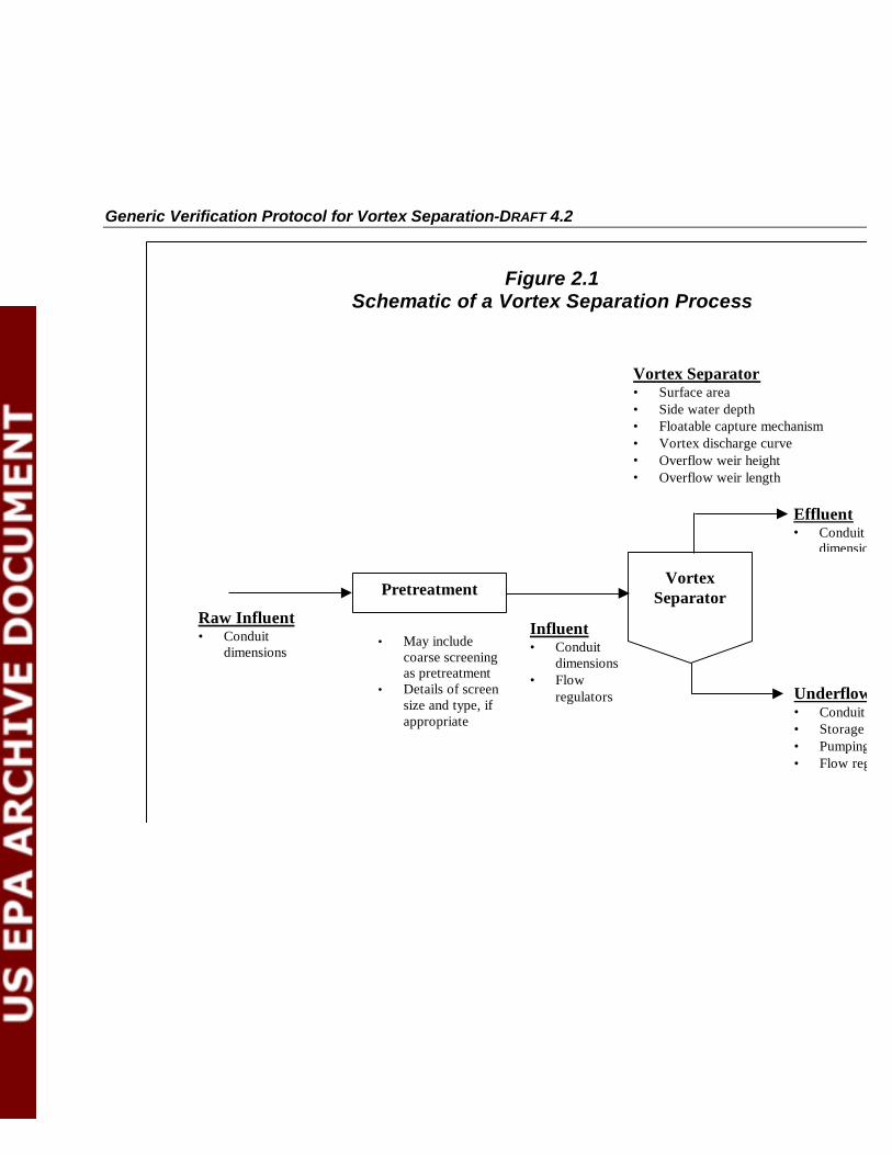
2.6 Equipment Description
A simple schematic of a typical vortex separation process for wet weather flow treatment is provided in Figure 2.1. All ancillary equipment used in verification testing shall be provided by the Manufacturer along with technical assistance and technical support on an as-needed basis to the FTO during the operation and monitoring of the equipment.
2-6
Generic Verification Protocol for Vortex Separation-DRAFT 4.2
Vortex Separator
Figure 2.1Schematic of a Vortex Separation Process
Influent • Conduit
dimensions • Flow
regulators
Vortex Separator • Surface area • Side water depth • Floatable capture mechanism • Vortex discharge curve • Overflow weir height • Overflow weir length
Raw Influent • Conduit
dimensions
Pretreatment
• May include coarse screening as pretreatment
• Details of screen size and type, if appropriate
Effluent • Conduit
dimensions
Underflow • Conduit dimensions • Storage volume (if any) • Pumping (if any) • Flow regulators
Generic Verification Protocol for Vortex Separation-DRAFT 4.2
The Test Plan(s) shall include the following information on the equipment to be tested:
• Full description of the vortex separator along with relevant photograph perspectives or schematics;
• A description of the scientific concepts on which the design of the equipment was based;
• A detailed description of physical condition of the equipment including its weight, ruggedness, and size;
• Definition of the range of flows for which the equipment is suitable for use;
• A detailed description of requirements of the equipment including general environmental requirements, limitations, and any consumables. The description shall also include an estimate of the range of underflow and overflow rates;
• Identification of any special licensing requirements associated with the operation of the equipment; and,
• Discussion of the factors which impact on the performance on the equipment.
In addition to providing the equipment, the Manufacturer shall attach data plates to each piece of equipment in an accessible location. The data plates shall, at a minimum, contain the following information:
• Equipment name;
• Model number; and,
• Manufacturer’s name and address.
2.7 Experimental Design
2.7.1 Purpose and Scope of Experimental Design
The purpose of the experimental design is to define the test conditions, performance measures, measurement requirements and data quality indicators for verification testing.
The elements that shall be considered in the experimental design are as follows:
• Verification testing objectives;
• Test equipment influent characteristics;
• Test equipment operating conditions;
• Test equipment performance measures;
• Other measured data; and,
2-8

Generic Verification Protocol for Vortex Separation-DRAFT 4.2
• Data quality indicators.
Verification testing objectives have been previously discussed in Section 2.2 and further discussion will not be added here. Guidance regarding the remaining aspects of the experimental design is presented in the following sub-sections.
2.7.2 Test Equipment Influent Characteristics
Results of any testing are only valid for the conditions under which the test is performed. As a result, the experimental design shall cover the range of events anticipated for a specific site in terms of both flow and influent quality.
The experimental design presented in the Test Plan shall indicate the minimum requirements for the nature (i.e., duration and range of flow and quality variation) and number of storm events to be used for testing.
Storm influent is the result of rainfall and/or snowmelt phenomena. Influent quality variations are generally observed through the course of a storm event. For purposes of verification testing, the duration of a storm event is defined as the period starting at the onset of rainfall and/or snowmelt induced flow increase until influent flows return to typical dry weather rates.
Correlation of influent flow data with rainfall or temperature measurements can help define the duration of storm events and is recommended though not mandatory.
2.7.2.1 Nature of Storm Events
Ideally, testing should reflect the full range of rainfall induced influent quantity and quality conditions the test equipment will need to treat.
The equipment shall be tested for a number of storm events that encompass flows exceeding 67% of the equipment design capacity (Qd) for any continuous period of a storm event, with a minimum duration of 3 times the hydraulic residence time (HRT), calculated using Qd and the total volume of the test equipment as supplied by the manufacturer.
The results of testing with sustained high flows (Q peak) ‡0.67 Qd for 3 times HRT shall be discretely reported as evidence indicative of performance under peak flow conditions.
Testing using storms producing influent flows <0.67 Qd (peak or otherwise) with total storm durations greater than 3 times test unit HRT calculated using Qd shall be acceptable. Results from testing with influent flows <0.67 Qd and the required duration shall be reported separately.
Storm events of duration less than 3 times the test unit HRT calculated at Qd, shall not be used for verification testing purposes.
2-9
Generic Verification Protocol for Vortex Separation-DRAFT 4.2
2.7.2.2 Number of Storm Events
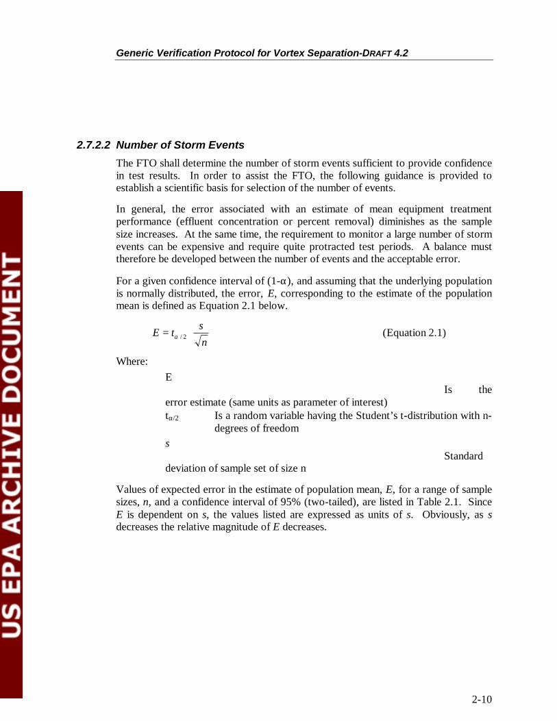
The FTO shall determine the number of storm events sufficient to provide confidence in test results. In order to assist the FTO, the following guidance is provided to establish a scientific basis for selection of the number of events.
In general, the error associated with an estimate of mean equipment treatment performance (effluent concentration or percent removal) diminishes as the sample size increases. At the same time, the requirement to monitor a large number of storm events can be expensive and require quite protracted test periods. A balance must therefore be developed between the number of events and the acceptable error.
For a given confidence interval of (1-a), and assuming that the underlying population is normally distributed, the error, E, corresponding to the estimate of the population mean is defined as Equation 2.1 below.
� s �E = ta / 2 �� �� (Equation 2.1)
Ł n ł Where:
E Is the
error estimate (same units as parameter of interest) ta/2 Is a random variable having the Student’s t-distribution with n
degrees of freedom s
Standard deviation of sample set of size n
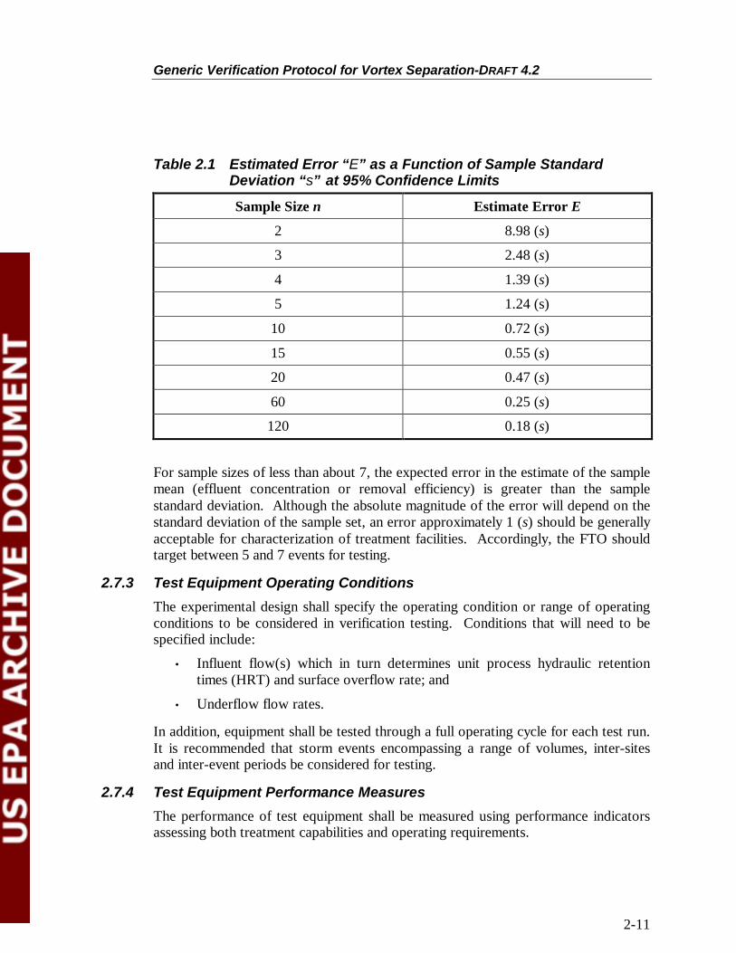
Values of expected error in the estimate of population mean, E, for a range of sample sizes, n, and a confidence interval of 95% (two-tailed), are listed in Table 2.1. Since E is dependent on s, the values listed are expressed as units of s. Obviously, as s decreases the relative magnitude of E decreases.
2-10
Generic Verification Protocol for Vortex Separation-DRAFT 4.2
Table 2.1 Estimated Error “E” as a Function of Sample Standard Deviation “s” at 95% Confidence Limits
Sample Size n Estimate Error E
2 8.98 (s)
3 2.48 (s)
4 1.39 (s)
5 1.24 (s)
10 0.72 (s)
15 0.55 (s)
20 0.47 (s)
60 0.25 (s)
120 0.18 (s)
For sample sizes of less than about 7, the expected error in the estimate of the sample mean (effluent concentration or removal efficiency) is greater than the sample standard deviation. Although the absolute magnitude of the error will depend on the standard deviation of the sample set, an error approximately 1 (s) should be generally acceptable for characterization of treatment facilities. Accordingly, the FTO should target between 5 and 7 events for testing.
2.7.3 Test Equipment Operating Conditions
The experimental design shall specify the operating condition or range of operating conditions to be considered in verification testing. Conditions that will need to be specified include:
• Influent flow(s) which in turn determines unit process hydraulic retention times (HRT) and surface overflow rate; and
• Underflow flow rates.
In addition, equipment shall be tested through a full operating cycle for each test run. It is recommended that storm events encompassing a range of volumes, inter-sites and inter-event periods be considered for testing.
2.7.4 Test Equipment Performance Measures
The performance of test equipment shall be measured using performance indicators assessing both treatment capabilities and operating requirements.
2-11

Generic Verification Protocol for Vortex Separation-DRAFT 4.2
2.7.4.1 Treatment Performance
The following performance indicators shall be determined for all core and supplemental parameters with the exception of floatables:
1. Flow-weighted average effluent concentration of the quality parameter of interest (Ceff p,t) for all core and supplemental performance parameters except floatables.
2. Gross removal efficiency calculated using flow-weighted average influent and effluent concentrations for the parameter of interest (GR p,t).
3. Net removal efficiency calculated using flow-weighted average influent and effluent concentrations for the parameter of interest (NR p,t).
4. Treatment factor calculated using flow-weighted average influent and underflow concentrations for the parameter of interest (TF p,t).
5. Concentration factor calculated using flow-weighted average effluent and underflow concentrations for the parameter of interest (CF p,t).
6. Flow Related Treatment Factor using flow-weighted average influent and overflow for the parameter of interest (FRTFp,t).1
The recommended flow-weighting scheme is based upon the incremental flow volume in the time interval prior to the sub-sample being taken.
Both the concentration and treatment efficiency performance indicators shall be calculated for the total storm.
The treatment performance indicators for all core parameters with the exception of floatables are calculated as follows:
�n
Ci , p DVi
Ceff p,t = i=1 n
� DVi i=1
(Equation 2.2)
Where: Ci,p (mg/L) Is the instantaneous concentration of quality
parameter p at the end of the ith sampling interval
1 Note that if representative underflow sampling proves too difficult due to low hydraulic surface loading rates, blocking of underflow tubes and lines, etc., an additional treatment performance measure may be calculated, the Flow Related Treatment Factor or ratio of Gross Removal Efficiency to the Flow Split. The flow split is the volumetric removal efficiency, or proportion of total inflow routed on to WWTP through the unit’s underflow.
2-12
Generic Verification Protocol for Vortex Separation-DRAFT 4.2
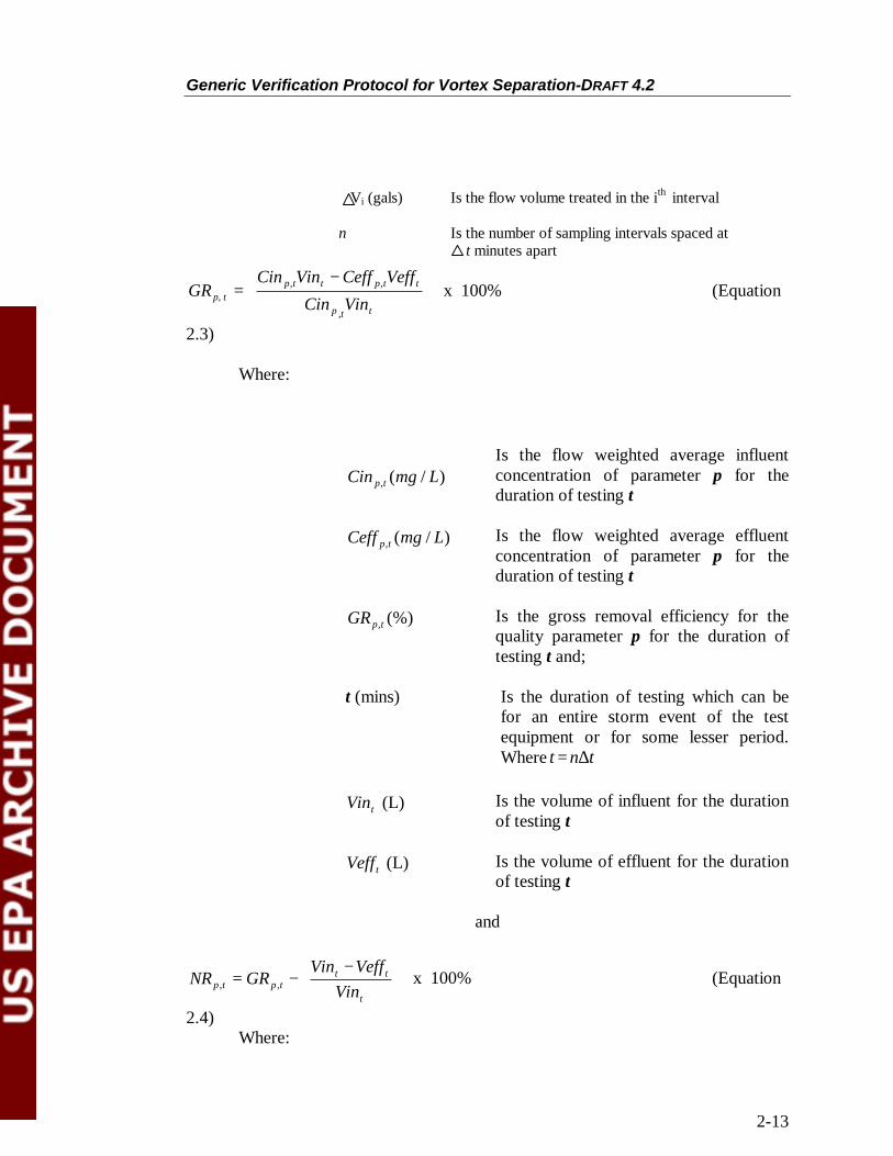
Vi (gals) Is the flow volume treated in the ith interval
n Is the number of sampling intervals spaced at t minutes apart
�Cin Vin - Ceff Veff � GRp, t = �
� p,t
Cint
Vint
p,t t
�� x 100% (Equation
Ł p ,t ł 2.3)
Where:
Is the flow weighted average influent Cin p,t (mg / L) concentration of parameter p for the
duration of testing t
Ceff p,t (mg / L) Is the flow weighted average effluent concentration of parameter p for the duration of testing t
GRp,t (%) Is the gross removal efficiency for the quality parameter p for the duration of testing t and;
t (mins) Is the duration of testing which can be for an entire storm event of the test equipment or for some lesser period. Where t = nDt
Vint (L) Is the volume of influent for the duration of testing t
tVeff (L) Is the volume of effluent for the duration of testing t
and
p tNR , = p tGR , - ��Ł � -
t
tt
Vin VeffVin
��ł �
x 100% (Equation
2.4) Where:
2-13

Generic Verification Protocol for Vortex Separation-DRAFT 4.2
NRp ,t Is the net removal efficiency for the parameter p over the duration of testing t
and
Cu p ,tTFp ,t = Cin p ,t
(Equation 2.5)
Where:
TFp,t Is the treatment factor for the parameter p over the duration of testing t
Cu p ,t (mg/L) Is the flow weighted average underflow concentration for the parameter p over duration of testing t
and Ceffp,tCFp,t = Cup,t
(Equation 2.6)
Where: CFp ,t Is the average concentration factor for the
parameter p over duration of testing t
The core quality parameters that shall be used for evaluating test equipment treatment performance are as follows:
• Total suspended solids – (TSS);
• Settleable solids
2-14

Generic Verification Protocol for Vortex Separation-DRAFT 4.2
• Floatables (see next section)
Supplemental quality parameters such as BOD5 or COD can be included in the Verification Report and Statement at the request of the Manufacturer provided appropriate sampling and analytical protocols have been followed. Representative methods or references for testing for core and supplemental parameters are listed in Table 2.2.
2-15

Generic Verification Protocol for Vortex Separation-DRAFT 4.2
Table 2.2 Testing Reference/Methodology for Core and Supplemental Parameters VORTEX
Parameter Reference or Methodology
TSS EPA 160.2
Settable Solids EPA 160.5
BOD5 EPA 405.1
COD EPA 410.1
SVD SOP Required
2.7.4.2 Treatment Performance – Floatables
To assess the performance of the vortex unit in removing floatables of certain sizes or buoyancies, the mass and volume of floatables can be used.
(FRE) The floatables removal efficiency for a Vortex separator can be defined as follows:
FRE = ( t
tt
Fin FeffFin - ) x 100% (Equation 2.7)
Where:
tFin (lbs, ft3) Is the floatables influent mass or volume for the duration of testing t
tFeff (lbs, ft3) Is the floatables effluent mass or volume for the duration of testing t
FRE Is the floatables removal efficiency based upon floatables mass, and/ or volume, and/ or surface area
All treatment performance measures shall be calculated for each test run with storms of duration >3 x HRT. Average of test runs of appropriate duration with peak flows ‡ 0.67 x Qd and with peak flows <0.67 x Qd shall be presented separately.
2-16

Generic Verification Protocol for Vortex Separation-DRAFT 4.2
2.7.4.3 Test Equipment Operations and Maintenance Performance Indicators
Both quantitative and qualitative performance indicators shall be evaluated to assess test equipment operations and maintenance performance.
Qualitative O&M performance indicators shall be prepared by the FTO, in conjunction with the Manufacturer and Owner and shall include:
• Observations regarding ease of operation during all phases of operation;
• Log of any operating problems recorded during testing;
• Quality of the O&M manual; and,
• Observations regarding labor requirements during all phases of operation.
Quantitative O&M performance indicators shall include:
• Duration in hours of typical start-up and shut-down/clean-out operations;
• Duration in hours of typical start-up and shut-down/clean-out operations;
• Measured headloss through the vortex separator;
• Underflow mass production measured as lbs./MG treated;
• Underflow volume production measured as gals/MG treated;
• Underflow characteristics:
- continuous or intermittent flow;
- average sludge flow during a test run measured as GPM;
- peak sludge flow during a test run measured as GPM.
All the O&M performance indicators shall be measured on a test by test basis. Indicator data shall be presented for each test as well as averages calculated for all testing segregated into storm events where peak flows are ‡ 0.67 Qd and < 0.67 Qd for durations > 3 x HRT.
2.7.5 Other Measured Data
Additional information needs to be collected to allow for interpretation of the verification statement from site to site. These include both influent and effluent quality characteristics and operational conditions.
2.7.5.1 Influent and Effluent Characteristics
Influent characteristics may vary significantly from site to site and event to event. As a result, there is a need to monitor parameters in addition to the core parameters to fully document the characteristics of the influent wastewater and the resulting effluent characteristics. The following is a recommended list of monitoring parameters to characterize the streams:
2-17

Generic Verification Protocol for Vortex Separation-DRAFT 4.2
• TSS*;
• Settling velocity distribution (SVD);
• Floatables*; and,
• Settleable solids*
Notes: *Core performance parameters
Other supplemental performance parameters may be included to more fully characterize the influent and effluent streams.
2.7.5.2 Operational parameters
All operating conditions need to be measured for each verification run for interpretation of results. The following is a list of the operating conditions which need to be measured for each run:
• All flows to the process;
• Underflow flows and variations;
• Measured headloss
2.7.6 Data Quality Indicators
Data quality indicators (DQIs) qualitative and quantitative descriptors are used in interpreting the degree of acceptability or utility of data. Principal DQIs include:
• Precision;
• Bias;
• Accuracy;
• Representativeness;
• Comparability; and,
• Completeness.
The acronym PARCC is often employed to stand for the principal DQIs.
The FTO shall determine acceptable values or qualitative descriptors for all PARCC indicators in advance of verification testing as part of the experimental design. The assessment of data quality will require specific field and laboratory procedures to determine the data quality indicators. All details of DQI selection and values shall be documented in the Test Plan. Reference shall be made to EPA Guidance for Quality Assurance Project Plans – Appendix D (EPA QA/G5, 1998) and Guidance for the Data Quality Objectives Process (EPA QA/G-4, 1994) for details.
2-18
Generic Verification Protocol for Vortex Separation-DRAFT 4.2
2.8 Quality Assurance
The FTO will be required to include discussion on quality assurance prior to the start of verification testing as part of the Test Plan. The quality assurance (QA) discussion will specify procedures that shall be used to ensure data quality and integrity. The FTO will need to adhere closely to the procedures specified to ensure that data generated by verification testing can serve as a basis for performance verification.
The discussion can be subdivided into the following main areas:
• Project management;
• Measurement/ data acquisition;
• Assessment/ oversight; and,
• Data validation and usability.
The following sections provide an overview of the requirements of each area. Specific information on the requirements is contained within the EPA Guidance for Quality Assurance Plans (EPA QA/G-5).
2.8.1 Project Management
The QA discussion shall include documentation on the management of the project, the project history and objectives, and the responsibilities of each of the participants. The purpose of this element is to ensure that the project approach and goals are clearly stated and understood by all participants. This area shall include a list of individuals involved in the project, their roles and responsibilities, a concise definition of the purpose of the study, a project schedule including a task organization chart, documentation of the data quality objectives, special training and certification requirements, and a complete list of required documentation for the study.
2.8.2 Measurement/Data Acquisition
The QA discussion shall include specific information on all aspects of the experimental design including a detailed description of each component. Specific requirements in the area of measurement and data acquisition are as follows:
• A schedule of project sampling, analysis, and peer review activities;
• Documentation of any assumptions made in the design of the experiment and all procedures for locating and selecting environmental samples;
• Validation of any non-standard sampling or measurement techniques to assess the potential impact on the representativeness of the data generated;
2-19

Generic Verification Protocol for Vortex Separation-DRAFT 4.2
• Description of the requirements for sampling handling and custody in the field, laboratory and in transport. The description shall include examples of sample labels, custody forms, and sample custody logs;
• Documentation of analytical methods and equipment and the specific performance for each method. be Reference shall be made to Standard Methods (APHA 1999 ) or USEPA Methods (EPA 6001/A-79-020);
• Identification of required measurement quality control checks for both the field and the laboratory. Information presented shall include the frequency of each type of QC check and references for the procedures used to calculate each of the QC statistics;
• Identification of all equipment calibration requirements including standards for calibration, and calibration methods;
• Identification of any types of data needed for project implementation obtained from non-measurement sources including definition of acceptance criteria and discussion on the limitations on the use of any such data.
2.8.3 Assessment
The QA discussion shall include a detailed section on the methods to be used to assess the effectiveness of the implementation of the QA/QC activities. Specifically, this section shall provide information on the types of assessments to be completed, description of response actions, and details on the types of reports to management to be completed.
The number, frequency and type of assessments activities to be used in the project shall be specified including a definition of the scope of the authority of the assessors and when they are authorized to act, how responses to non-conforming conditions would be addressed and the individuals responsible for implementation of the response action.
2.8.4 Data Validation and Usability
Data validation and usability will ensure that individual data collected conform to specific criteria developed to ensure data reconciliation with the project’s objectives. QA activities will form the bulk of data validation and usability. The QA discussion will need to include specific information on data review, validation, and verification requirements including the criteria used to review and validate data, validation and verification methods, and reconciliation with data quality objectives.
As part of the assessment of data quality, five data quality indicators (DQI) can be used to interpret the degree of acceptability or utility of the data. The QA discussion shall include a protocol for assessing these five data quality indicators and acceptable
2-20
Generic Verification Protocol for Vortex Separation-DRAFT 4.2
limits and criteria for each of these indicators. (See Section 2.7 Experimental Design).
2.9 Health Safety and Environmental Plan
The Test Plan shall include details on safety procedures to be followed during the fieldwork. Safety conditions addressed shall include the following:
• Storage, handling and disposal of hazardous chemicals;
• Conformance with applicable electrical and plumbing codes at the test site;
• Ventilation equipment for trailers or buildings housing equipment if gases are present which may pose a safety hazard;
• Any other specific safety or environmental issues associated with a specific piece of equipment; and,
• Any permitting requirements for directly discharged effluents.
• Confined space entry.
2-21

Generic Verification Protocol for Vortex Separation-DRAFT 4.2
3. VERIFICATION TESTING
The objective of verification testing is to operate the treatment equipment provided by the Manufacturer and assess its ability to meet the effluent concentration goals and removal efficiencies when treating wet weather flow.
Vortex separation equipment will be operated for verification testing purposes on CSOs.
3.1 Nature of Influent
Verification testing shall be based upon testing over a number of storm events. (See Section 2.6.3).
The nature of influent(s) and the number of events used in verification testing will be the decision of the FTO. In any event, the details of the proposed number and nature of testing events shall be documented in the Test Plan.
3.1.1 Operating Cycle
Each test shall be comprised of a complete operating cycle consisting of the following:
• Start-up Phase;
• Normal Dynamic Operation Phase; and,
• Shutdown Phase.
The start-up phase will consist of allowing the separator to fill before effluent discharge begins.
Normal dynamic operation refers to the period after filling when influent is continuing to enter the vortex separator. During this period, the influent flows and/or quality characteristics will be varying according to the wet weather conditions being encountered up to the maximum flow handling capacity of the equipment. The duration of this phase will be dependent on the wet weather event experienced or the duration of testing.
For small events, influent to the vortex separation device may not be sufficient to fill the unit completely. A vortex may not be formed and no overflow from the unit will occur. In this case, normal dynamic operation will not occur.
Following a storm, the influent flow rate will drop below the underflow rate and the volume in the cortex vessel will fall. At this point, the underflow will continue until the tank is completely drained. This period is termed the shutdown phase.
3-1

Generic Verification Protocol for Vortex Separation-DRAFT 4.2
3.1.2 Measured Parameters and Measured Process Stream
Verification testing shall include the following measured parameters:
• Core treatment performance parameters;
• Any supplemental performance parameters selected by the FTO;
• Treatability parameters; and,
• All measurements supporting determination of Operations and Maintenance performance parameters.
Measured process streams during verification testing shall include:
• Influent to test equipment;
• Effluent from test equipment;
• Underflow from test equipment; and,
• Any captured residuals (e.g. floatables).
3.1.3 Sampling and Monitoring Strategy
Sampling of all streams shall be carried out at a representative location using industry standard procedures. Automatic samples may be employed for sampling but it will be incumbent upon the FTO to demonstrate that the use of automatic sampling equipment does not bias test results.
For all parameters with the exception of floatables, the estimation of treatment performance efficiencies for each core parameter for various durations, requires that sequential sub-samples be collected. The FTO shall collect discrete samples at predetermined time intervals (Dt) during the entire duration of verification testing.
A protocol for floatables sampling was recently developed for New York City (Monitoring and Sampling Plan, Corona Avenue Vortex Facility, New York City Bureau of Environmental (Engineering, 1999). Reference should be made to this document for details of floatables sampling.
It is recognized that for storm events, it is difficult, if not impossible, to predict the exact duration of a particular event. At the same time, when automatic sampling equipment is employed, the total duration of sampling must be pre-determined. The FTO shall review rainfall and influent flow (e.g. CSO or stormwater) historical data and determine the appropriate frequency and number of sub-samples based upon this information. If the review of historical data finds evidence that the influent flow shows a “first flush” phenomena, sampling shall be more frequent during the “first flush” phase of testing.
3-2

Generic Verification Protocol for Vortex Separation-DRAFT 4.2
It is recommended that continuous flow monitoring of the influent, overflow, and underflow streams also be undertaken. The FTO may adopt alternative monitoring approaches but will be required to document the details of these approaches and to provide assurance that alternative approaches will produce appropriate data quality.
3-3

Generic Verification Protocol for Vortex Separation-DRAFT 4.2
4. DATA ASSESSMENT AND REPORTING
4.1 Data Assessment
Verification testing will generate a significant amount of data. All raw data shall be included along with all analysis results in the Verification Report. Raw data shall be included in hard copy form and in electronic format. Data in electronic format shall be included in generally commercially available programs for word processing, spreadsheet or database processing, or commercial software developed especially for data collection and processing on a specific hardware instrument or piece of equipment.
Data assessment steps shall include:
• Data verification/ Validation confirming that requirements of QC acceptance have been met. (e.g. comparison of DQIs);
• Data reduction, summarizing and/ or averaging data; and,
• Synthesis of results into tables and charts.
The Verification Report shall be a comprehensive document containing all raw and analyzed data, all QA/QC data sheets, a description of all types of data collected, a detailed description of the testing procedure and methods, results and QA/QC results. The Test Plan(s) shall also be included as part of the Verification Report.
All raw test data shall be included in the verification test study records. Raw test data includes all paper records including field notebooks, bench sheets, field data sheets, custody sheets, and instrument printouts.
4-1
Generic Verification Protocol for Vortex Separation-DRAFT 4.2
4.2 Performance Results
4.2.1 Treatment Performance
Results will be presented in the Verification Report and Verification Statement for monitored storms of duration > 3 x HRT. Results shall be stratified into two groups for peak flows ‡ 0.67 Qd and for peak flows < 0.67 Qd. The following shall be reported:
• Average effluent concentrations and 95% confidence intervals for the full storm or the duration of sampling (Ceff);
• Gross removal efficiency from influent to effluent and 95% confidence intervals (GR);
• Verification in removal efficiency related to intra-events in flow.
• Net removal efficiency and 95% confidence intervals (NR);
• Treatment factor (TF);
• Concentration factor (CF); and,
• Time variation of effluent concentrations.
For each concentration and removal efficiency parameter, average results from each verification run completed along with their 95% confidence intervals will be presented. Overall averages segregated by peak flow (‡ 0.67 Qd and < 0.67 Qd) shall also be calculated and presented along with their 95% confidence intervals.
Data analysis should be included to assess variations in performance or removal efficiency related to intra-event variations in flow. The removal data should be paired with the actual flows through the unit; the data shall be presented as removal efficiencies over various flow rates. This information is needed to determine if the unit performs over a limited range of flow rates, or if it performs with minor variations over a wide range of flow rates. This information is crucial for selecting a technology and sizing a facility.
For the analytical data obtained during the verification testing, 95% confidence intervals shall be calculated by the FTO for core parameter effluent concentrations and removal efficiencies. As the name implies, a confidence interval describes the range in which any population measurement may exist with a specified percent confidence. The following formula can be employed for confidence interval calculation for normally distributed parameters:
where:
X n ) ( Equation 4.1 )95%Confidence Interval = X –tn- 1,0.975 (S /
4-2

Generic Verification Protocol for Vortex Separation-DRAFT 4.2
Is the sample mean;
S Is the
sample standard deviation;
n Is the number of independent measurements in the data set; and,
t Is the Student’s distribution value with n-1 degrees of freedom
Please note that Section 4.2.1 is based on the assumption that the results obtained from analysis of samples will be normally distributed. This may not be the case; it may be obvious that a graph of the data would be skewed. In such instances, it may be more appropriate to apply the relevant statistics to the log transforms of the basic data and then apply the relevant inverse transforms as appropriate. In other words, a log normal distribution may need to be determined to obtain a nearly normal distribution.
4.2.2 O&M Performance
The following data or information shall be presented in the Verification Report and Verification Statement regarding test equipment operations and maintenance performance:
Qualitative O&M performance indications shall include:
• Observations regarding ease of operation during all phases of operation;
• Log of any operating problems recorded during testing;
• Quality of the O&M manual; and,
• Observations regarding labour requirements during all phases of operation.
Quantitative O&M performance indicators shall include:
• Duration in hours of typical start-up and shut-down/clean-out operations;
• Electrical consumption (if appropriate) for all unit processes measured as kWh per MG treated;
4-3
Generic Verification Protocol for Vortex Separation-DRAFT 4.2
• Consumables unit cost measured as $ per MG treated. Unit costs used for this calculation as well as an appropriate cost index value (e.g. ENR index) shall also be presented as supporting information;
• Waste sludge mass production measured as lbs./MG treated;
• Waste sludge volume production measured as gals/MG treated;
• Waste sludge flow characteristics:
- continuous or intermittent flow;
- average sludge flow during a test run measured as gpm;
- peak sludge flow during a test run measured as gpm.
All the O&M performance indicators shall be measured on a test by test basis. Indicator data shall be presented for each test as well as averages calculated for testing stratified by flows (peak ‡ 0.67 Qd and peak flow < 0.67 Qd).
4.2.3 Other Measured Data
All other measured data including the following shall also be reported in the Verification Report:
Influent and Effluent Characteristics
All influent and effluent data for core and supplemental treatment performance parameters shall be presented as indicated in Section 4.2.1. Influent and effluent treatability parameters shall include the following:
• Settling velocity distribution.
Flow weighted average concentration and data range shall be presented for each test run. Actual storm influent data shall also be differentiated for storms with Q peak ‡ 0.67 Qd and Q peak < 0.67 Qd. All test run data shall be averaged across all runs and presented as average and range.
Measured Operational Parameters
Measured operational parameters shall include:
• Influent and effluent flows;
• Underflow flows; and,
• Electrical utilization (if appropriate).
For actual and simulated influent test runs, the FTO shall report the following in addition to the requirements in Section 4.2.2:
• The time variation of influent, effluent and underflow flows;
4-4

Generic Verification Protocol for Vortex Separation-DRAFT 4.2
• Average and peak influent and effluent flow rates;
• Total volume of effluent, influent and underflow/sludge produced; and,
• Electrical utilization (if appropriate) in kWh for the test run.
Data shall be reported for each test run and clearly indicated as simulated or actual storm influent and again for actual influents, be differentiated as Q peak ‡ 0.67 Qd or Q peak < 0.67 Qd.
Calculated Operational Parameters
Calculated operational parameters shall include the following in addition to the data requested in Section 4.2.2.
• Vortex vessel HRT and surface overflow rate (SOR) calculated for average and peak flows during a test run.
Calculated operation parameters shall be evaluated and presented for each storm influent test run and again be differentiated by the Q peak criterion.
4.3 Verification Report The FTO shall prepare a draft Verification Report describing the verification testing that was carried out and the results of that testing. The Verification report shall undergo a complete review by NSF International and the EPA, as well as a peer review as recommended by the Technology Panel on High Rate Separation. The vendor shall review and be provided the opportunity for input on its content. This report should fully describe the technology and the verification of its performance characteristics. At a minimum, shall include the following items:
• Introduction • Executive Summary • Description and Identification of Product Tested • Procedures and Methods Used in Testing • Results and Discussion • Conclusions and Recommendations
4.4 Verification Statement
NSF and EPA shall prepare a Verification Statement that briefly summarizes the Verification Report for issuance to the technology vendor. TheVerification Statement shall provide a brief description of the testing conducted and a synopsis of the performance results. The Statement is intended to provide vendors a tool by which to promote the strengths and benefits of their produc
4-5

Generic Verification Protocol for Vortex Separation-DRAFT 4.2
5. REFERENCES
ANSI/ASQC: Specifications and Guidelines for Quality Systems for Environmental Data Collection and Environmental Technology Programs (E4), 1994.
United States Environmental Protection Agency: Environmental Technology Verification Program-Quality and Management Plan for the Pilot Period (1995 – 2000), EPA/600/R-98/064, 1998. Office of Research and Development, Cincinnati, Ohio.
New York City Bureau of Environmental Engineering, Monitoring and Sampling Plan Corona Avenue Vortex Facility, 1999, New York City.
NSF International, Quality Management Plan, ETV Pilot – Wet Weather Flow Technologies, 2000. Ann Arbor, Michigan
United States Environmental Protection Agency, Methods for Analysis of Water and Wastes, EPA/600/4-79-020. Office of Research and Development, Washington, D.C.
APHA, AWWA, and WEF: Standard Methods for the Examination of Water and Wastewater. Washington, D.C. 20th Edition, 1999.
United States Environmental _Protection Agency: EPA Guidance for Quality Assurance Project Plans, EPA QA/G-5, EPA/600/R-98-018, 1998. Office of Research and Development, Washington, D.C.
United States Environmental Protection Agency, Guidance for the Data Quality Objectives Process, EPA QA/G-4, EPA/600/R-96-055, 1996. Office of Research and Development, Washington, D.C.
United States Environmental Protection Agency, Field Evaluation of a Swirl Degritter at Tamworth, New South Wales, Australia, EPA/600/R-81-063. Municipal Environmental Research Laboratory, Edison, New Jersey, 08817.
Journal of the New England Water Environment Association “Swirl Technology: Proper Design, Application and Evaluation” by Richard Field, Thomas P. O’Connor, and Howard Cowan, May 1995.
Journal of Environmental Engineering , ASCE Div., “Swirl Technology: Enhancement of Design, Evaluation, and Apllication” by Richard Field and Thomas P. O’Connor, August 1996.
5-1
XCG File #3-1077-01
DRAFT VERSION 4.2
GENERIC VERIFICATION PROTOCOL FOR
VORTEX SEPARATION
MAY 26,2000
Submitted to:
NSF INTERNATIONAL
789 DIXBORO ROAD
ANN ARBOR, MICHIGAN 48105
Submitted by:
XCG CONSULTANTS LTD.1 PORT STREET EAST, SUITE 201
MISSISSAUGA, ONTARIO
L5G 4N1
With Support From The:
U.S. ENVIRONMENTAL PROTECTION AGENCY ENVIRONMENTAL TECHNOLOGY VERIFICATION PROGRAM

TABLE OF CONTENTS Page No.
TABLE OF CONTENTS.................................................................................................. iACKNOWLEDGEMENTS AND PREFACE:....................................................................... iiiGLOSSARY OF TERMS................................................................................................ iv1. INTRODUCTION................................................................................................ i
1.1 The Environmental Technologies Verification Program .................. 1-11.2 Verification Testing Process............................................................ 1-21.3 Purpose and Scope of Protocol ........................................................ 1-41.4 Vortex Separation ........................................................................... 1-41.5 Considerations in Verification Testing ............................................ 1-5
1.5.1 Range of Testing ................................................................. 1-51.5.2 Performance Indicators and Quality Parameters................... 1-5
2. PLANNING… … … … … … … … … … … … … … … … … … … … … … … … … … … 2-1 2.1 Development of the Test Plan.......................................................... 2-12.2 Purpose of Verification Testing ........................................................ 2-12.3 Equipment Verification Testing Responsibilities ............................. 2-2
2.3.1 Responsibilities of Field Testing Organization..................... 2-22.3.2 Responsibilities of Manufacturer ......................................... 2-32.3.3 Responsibilities of the Owner .............................................. 2-32.3.4 Responsibilities of NSF ....................................................... 2-32.3.5 Responsibilities of USEPA .................................................. 2-4
2.4 Site Characterization ........................................................................ 2-42.5 Influent Characterization .................................................................. 2-5
2.5.1 Flow Characterization.......................................................... 2-52.5.2 Quality Characterization ...................................................... 2-5
2.6 Equipment Description..................................................................... 2-62.7 Experimental Design ........................................................................ 2-8
2.7.1 Purpose and Scope of Experimental Design ......................... 2-82.7.2 Test Equipment Influent Characteristics............................... 2-92.7.3 Test Equipment Operating Conditions ............................... 2-112.7.4 Test Equipment Performance Measures ............................. 2-112.7.5 Other Measured Data......................................................... 2-172.7.6 Data Quality Indicators...................................................... 2-18
2. 8 Quality Assurance .......................................................................... 2-192.8.1 Project Management .......................................................... 2-192.8.2 Measurement/Data Acquisition.......................................... 2-192.8.3 Assessment........................................................................ 2-202.8.4 Data Validation and Usability ............................................ 2-20
2.9 Health Safety and Environmental Plan ........................................... 2-213. VERIFICATION TESTING ............................................................................... 3-1
3.1 Nature of Influent............................................................................. 3-1
i
3.1.1 Operating Cycle................................................................... 3-13.1.2 Measured Parameters and Measured Process Stream............ 3-23.1.3 Sampling and Monitoring Strategy ...................................... 3-2
4. DATA ASSESSMENT AND REPORTING............................................................. 4-14.1 Data Assessment .............................................................................. 4-14.2 Performance Results......................................................................... 4-2
4.2.1 Treatment Performance........................................................ 4-24.2.2 O&M Performance .............................................................. 4-34.2.3 Other Measured Data........................................................... 4-4
4.3 Verification Report .......................................................................... 4-44.4 Verification Statement...................................................................... 4-5
5. REFERENCES.................................................................................................... 5-1
FIGURES
Figure 1.1 Verification Testing Process............................................................ 1-2Figure 2.1 Schematic of a Vortex Separation Process....................................... 2-7
TABLES
Table 2.1 Estimated Error "E" as a Function of Sample Standard Deviation "s" at 95% Confidence Limits ............................................................. 2-11
Table 2.2 Parameters and Reference or Methodology ................................... 2-16
ii