
Generic unwanted emission characteristics of … · Generic unwanted emission characteristics of...
95
Recommendation ITU-R M.2071-1 (02/2017) Generic unwanted emission characteristics of mobile stations using the terrestrial radio interfaces of IMT-Advanced M Series Mobile, radiodetermination, amateur and related satellite services
Transcript of Generic unwanted emission characteristics of … · Generic unwanted emission characteristics of...
Recommendation ITU-R M.2071-1 (02/2017)
Generic unwanted emission characteristics of mobile stations using
the terrestrial radio interfaces of IMT-Advanced
M Series
Mobile, radiodetermination, amateur
and related satellite services
ii Rec. ITU-R M.2071-1
Foreword
The role of the Radiocommunication Sector is to ensure the rational, equitable, efficient and economical use of the radio-
frequency spectrum by all radiocommunication services, including satellite services, and carry out studies without limit
of frequency range on the basis of which Recommendations are adopted.
The regulatory and policy functions of the Radiocommunication Sector are performed by World and Regional
Radiocommunication Conferences and Radiocommunication Assemblies supported by Study Groups.
Policy on Intellectual Property Right (IPR)
ITU-R policy on IPR is described in the Common Patent Policy for ITU-T/ITU-R/ISO/IEC referenced in Annex 1 of
Resolution ITU-R 1. Forms to be used for the submission of patent statements and licensing declarations by patent holders
are available from http://www.itu.int/ITU-R/go/patents/en where the Guidelines for Implementation of the Common
Patent Policy for ITU-T/ITU-R/ISO/IEC and the ITU-R patent information database can also be found.
Series of ITU-R Recommendations
(Also available online at http://www.itu.int/publ/R-REC/en)
Series Title
BO Satellite delivery
BR Recording for production, archival and play-out; film for television
BS Broadcasting service (sound)
BT Broadcasting service (television)
F Fixed service
M Mobile, radiodetermination, amateur and related satellite services
P Radiowave propagation
RA Radio astronomy
RS Remote sensing systems
S Fixed-satellite service
SA Space applications and meteorology
SF Frequency sharing and coordination between fixed-satellite and fixed service systems
SM Spectrum management
SNG Satellite news gathering
TF Time signals and frequency standards emissions
V Vocabulary and related subjects
Note: This ITU-R Recommendation was approved in English under the procedure detailed in Resolution ITU-R
1.
Electronic Publication
Geneva, 2017
ITU 2017
All rights reserved. No part of this publication may be reproduced, by any means whatsoever, without written permission of ITU.
Rec. ITU-R M.2071-1 1
RECOMMENDATION ITU-R M.2071-1*
Generic unwanted emission characteristics of mobile stations using
the terrestrial radio interfaces of IMT-Advanced
(Question ITU-R 229 3/5)
(2015-2017)
Scope
This Recommendation provides the generic unwanted emission characteristics of mobile stations using the
terrestrial radio interfaces of IMT-Advanced, suitable for establishing the technical basis for global circulation
of IMT-Advanced terminals. The information about unwanted emissions included in this Recommendation
could also be used as guidance by Administrations for cases not specifically covered herein. Implementation
of characteristics of mobile stations using the terrestrial radio interfaces of IMT-Advanced in any of the bands
included in this Recommendation is subject to compliance with the Radio Regulations.
Keywords
IMT-Advanced, emission characteristics, out-of-band, unwanted, mobile station
The ITU Radiocommunication Assembly,
considering
a) that unwanted emissions consist of both spurious and out-of-band (OoB) emissions according
to No. 1.146 of the Radio Regulations (RR) and that spurious and OoB emissions are defined in
RR Nos. 1.145 and 1.144, respectively;
b) that limitation of the maximum permitted levels of unwanted emissions of IMT-Advanced
mobile stations (MSs) is necessary to protect other radio systems and services from interference and
to enable coexistence between different technologies;
c) that too stringent limits may lead to an increase in size or in complexity of IMT-Advanced
radio equipment;
d) that every effort should be made to keep limits for unwanted emissions at the lowest possible
values taking account of economic factors and technological limitations;
e) that Recommendation ITU-R SM.329 relates to the effects, measurements and limits to be
applied to spurious domain emissions;
f) that the same spurious emission limits apply equally to MSs of all radio interfaces;
g) that Recommendation ITU-R SM.1541 relating to OoB emission specifies generic limits in
the OoB domain which generally constitute the least restrictive OoB emission limits and encourages
the development of more specific limits for each system;
h) that the levels of spurious emissions of IMT-Advanced terminals shall comply with the limits
specified in RR Appendix 3;
i) that Recommendation ITU-R M.1579 establishes the technical basis for global circulation of
IMT-2000 and IMT-Advanced MSs;
* This Recommendation should be brought to the attention of Radiocommunication Study Group 1.
2 Rec. ITU-R M.2071-1
j) that one of the basic requirements of global circulation is that the MS does not cause harmful
interference in any country where it is taken;
k) that the harmonization of unwanted emission limits will facilitate global use and access to a
global market;
l) that unwanted emission limits are dependent on the transmitter emission characteristics in
addition to depending on services operating in other bands;
m) that the technology used by a system and its conformance with the recommended
specifications and standards in Recommendation ITU-R M.2012 defines that system as
IMT-Advanced regardless of the frequency band of operation,
noting
a) the work carried out by standardization bodies to define limits to protect other radio systems
and services from interference and to enable coexistence between different technologies;
b) that IMT-Advanced mobile stations must comply with local, regional, and international
regulations for OoB and spurious emissions relevant to their operations, wherever such regulations
apply;
c) that the notes and annexes of this Recommendation – being based on the ongoing work in
standardization bodies – in order to reflect the wide applicability of IMT-Advanced technologies and
to maintain consistency with the technology specifications, may contain material which reflects
information related to the technology applications in bands other than those identified for IMT,
noting further
that there are ongoing studies within ITU-R regarding the protection of other services from unwanted
emissions of IMT-Advanced stations to address further cases of compatibility,
recommends
1 that the unwanted emission characteristics of IMT-Advanced mobile stations should be based
on the limits contained in the technology specific Annexes 1 and 2 which correspond to the terrestrial
radio interface specifications referenced in recommends 1 of Recommendation ITU-R M.2012;
2 that the unwanted emission characteristics of IMT-Advanced mobile stations in Annexes
1 and 2 should apply in Regions and countries in which corresponding bands are identified for IMT
in the Radio regulations**.
Annex 1 – LTE-Advanced1
Annex 2 – WirelessMAN-Advanced2
** In other cases the unwanted emission characteristics of IMT-Advanced mobile stations in Annexes 1 and 2
are provided for information. Administrations may choose to apply the unwanted characteristics in
Annexes 1 and 2 for the bands not identified for IMT at their national level, bearing in mind global
circulation aspects.
1 Developed by 3GPP as LTE Release 10 and Beyond (LTE-Advanced).
2 Developed by IEEE as the WirelessMAN-Advanced specification incorporated in IEEE Std 802.16
beginning with approval of IEEE Std 802.16m.
Rec. ITU-R M.2071-1 3
Annex 1
LTE-Advanced
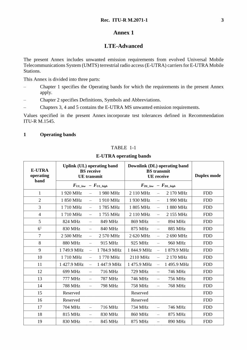
The present Annex includes unwanted emission requirements from evolved Universal Mobile
Telecommunications System (UMTS) terrestrial radio access (E-UTRA) carriers for E-UTRA Mobile
Stations.
This Annex is divided into three parts:
– Chapter 1 specifies the Operating bands for which the requirements in the present Annex
apply.
– Chapter 2 specifies Definitions, Symbols and Abbreviations.
– Chapters 3, 4 and 5 contains the E-UTRA MS unwanted emission requirements.
Values specified in the present Annex incorporate test tolerances defined in Recommendation
ITU-R M.1545.
1 Operating bands
TABLE 1-1
E-UTRA operating bands
E-UTRA
operating
band
Uplink (UL) operating band
BS receive
UE transmit
Downlink (DL) operating band
BS transmit
UE receive Duplex mode
FUL_low – FUL_high FDL_low – FDL_high
1 1 920 MHz – 1 980 MHz 2 110 MHz – 2 170 MHz FDD
2 1 850 MHz – 1 910 MHz 1 930 MHz – 1 990 MHz FDD
3 1 710 MHz – 1 785 MHz 1 805 MHz – 1 880 MHz FDD
4 1 710 MHz – 1 755 MHz 2 110 MHz – 2 155 MHz FDD
5 824 MHz – 849 MHz 869 MHz – 894 MHz FDD
61 830 MHz – 840 MHz 875 MHz – 885 MHz FDD
7 2 500 MHz – 2 570 MHz 2 620 MHz – 2 690 MHz FDD
8 880 MHz – 915 MHz 925 MHz – 960 MHz FDD
9 1 749.9 MHz – 1 784.9 MHz 1 844.9 MHz – 1 879.9 MHz FDD
10 1 710 MHz – 1 770 MHz 2110 MHz – 2 170 MHz FDD
11 1 427.9 MHz – 1 447.9 MHz 1 475.9 MHz – 1 495.9 MHz FDD
12 699 MHz – 716 MHz 729 MHz – 746 MHz FDD
13 777 MHz – 787 MHz 746 MHz – 756 MHz FDD
14 788 MHz – 798 MHz 758 MHz – 768 MHz FDD
15 Reserved Reserved FDD
16 Reserved Reserved FDD
17 704 MHz – 716 MHz 734 MHz – 746 MHz FDD
18 815 MHz – 830 MHz 860 MHz – 875 MHz FDD
19 830 MHz – 845 MHz 875 MHz – 890 MHz FDD
4 Rec. ITU-R M.2071-1
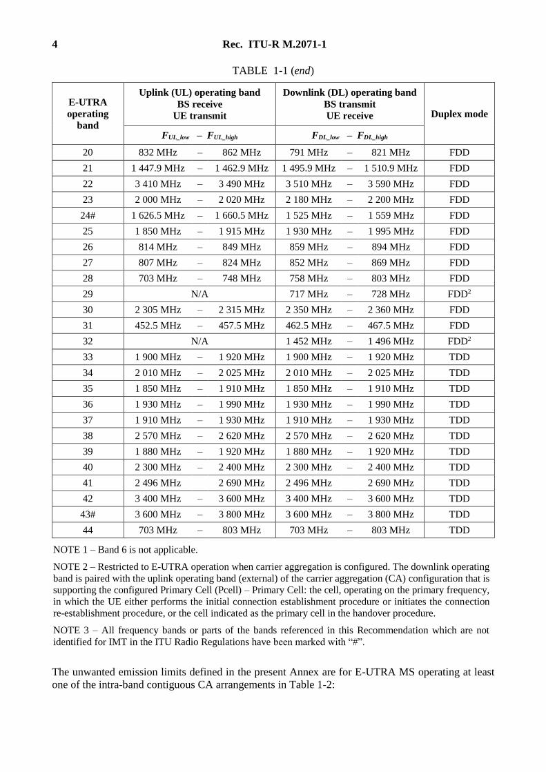
TABLE 1-1 (end)
E-UTRA
operating
band
Uplink (UL) operating band
BS receive
UE transmit
Downlink (DL) operating band
BS transmit
UE receive Duplex mode
FUL_low – FUL_high FDL_low – FDL_high
20 832 MHz – 862 MHz 791 MHz – 821 MHz FDD
21 1 447.9 MHz – 1 462.9 MHz 1 495.9 MHz – 1 510.9 MHz FDD
22 3 410 MHz – 3 490 MHz 3 510 MHz – 3 590 MHz FDD
23 2 000 MHz – 2 020 MHz 2 180 MHz – 2 200 MHz FDD
24# 1 626.5 MHz – 1 660.5 MHz 1 525 MHz – 1 559 MHz FDD
25 1 850 MHz – 1 915 MHz 1 930 MHz – 1 995 MHz FDD
26 814 MHz – 849 MHz 859 MHz – 894 MHz FDD
27 807 MHz – 824 MHz 852 MHz – 869 MHz FDD
28 703 MHz – 748 MHz 758 MHz – 803 MHz FDD
29 N/A 717 MHz – 728 MHz FDD2
30 2 305 MHz – 2 315 MHz 2 350 MHz – 2 360 MHz FDD
31 452.5 MHz – 457.5 MHz 462.5 MHz – 467.5 MHz FDD
32 N/A 1 452 MHz – 1 496 MHz FDD2
33 1 900 MHz – 1 920 MHz 1 900 MHz – 1 920 MHz TDD
34 2 010 MHz – 2 025 MHz 2 010 MHz – 2 025 MHz TDD
35 1 850 MHz – 1 910 MHz 1 850 MHz – 1 910 MHz TDD
36 1 930 MHz – 1 990 MHz 1 930 MHz – 1 990 MHz TDD
37 1 910 MHz – 1 930 MHz 1 910 MHz – 1 930 MHz TDD
38 2 570 MHz – 2 620 MHz 2 570 MHz – 2 620 MHz TDD
39 1 880 MHz – 1 920 MHz 1 880 MHz – 1 920 MHz TDD
40 2 300 MHz – 2 400 MHz 2 300 MHz – 2 400 MHz TDD
41 2 496 MHz 2 690 MHz 2 496 MHz 2 690 MHz TDD
42 3 400 MHz – 3 600 MHz 3 400 MHz – 3 600 MHz TDD
43# 3 600 MHz – 3 800 MHz 3 600 MHz – 3 800 MHz TDD
44 703 MHz – 803 MHz 703 MHz – 803 MHz TDD
NOTE 1 – Band 6 is not applicable.
NOTE 2 – Restricted to E-UTRA operation when carrier aggregation is configured. The downlink operating
band is paired with the uplink operating band (external) of the carrier aggregation (CA) configuration that is
supporting the configured Primary Cell (Pcell) – Primary Cell: the cell, operating on the primary frequency,
in which the UE either performs the initial connection establishment procedure or initiates the connection
re-establishment procedure, or the cell indicated as the primary cell in the handover procedure.
NOTE 3 – All frequency bands or parts of the bands referenced in this Recommendation which are not
identified for IMT in the ITU Radio Regulations have been marked with “#”.
The unwanted emission limits defined in the present Annex are for E-UTRA MS operating at least
one of the intra-band contiguous CA arrangements in Table 1-2:
Rec. ITU-R M.2071-1 5
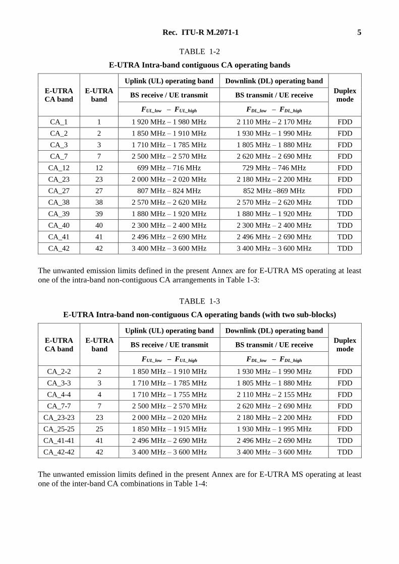
TABLE 1-2
E-UTRA Intra-band contiguous CA operating bands
E-UTRA
CA band
E-UTRA
band
Uplink (UL) operating band Downlink (DL) operating band
Duplex
mode BS receive / UE transmit BS transmit / UE receive
FUL_low – FUL_high FDL_low – FDL_high
CA_1 1 1 920 MHz – 1 980 MHz 2 110 MHz – 2 170 MHz FDD
CA_2 2 1 850 MHz – 1 910 MHz 1 930 MHz – 1 990 MHz FDD
CA_3 3 1 710 MHz – 1 785 MHz 1 805 MHz – 1 880 MHz FDD
CA_7 7 2 500 MHz – 2 570 MHz 2 620 MHz – 2 690 MHz FDD
CA_12 12 699 MHz – 716 MHz 729 MHz – 746 MHz FDD
CA_23 23 2 000 MHz – 2 020 MHz 2 180 MHz – 2 200 MHz FDD
CA_27 27 807 MHz – 824 MHz 852 MHz –869 MHz FDD
CA_38 38 2 570 MHz – 2 620 MHz 2 570 MHz – 2 620 MHz TDD
CA_39 39 1 880 MHz – 1 920 MHz 1 880 MHz – 1 920 MHz TDD
CA_40 40 2 300 MHz – 2 400 MHz 2 300 MHz – 2 400 MHz TDD
CA_41 41 2 496 MHz – 2 690 MHz 2 496 MHz – 2 690 MHz TDD
CA_42 42 3 400 MHz – 3 600 MHz 3 400 MHz – 3 600 MHz TDD
The unwanted emission limits defined in the present Annex are for E-UTRA MS operating at least
one of the intra-band non-contiguous CA arrangements in Table 1-3:
TABLE 1-3
E-UTRA Intra-band non-contiguous CA operating bands (with two sub-blocks)
E-UTRA
CA band
E-UTRA
band
Uplink (UL) operating band Downlink (DL) operating band
Duplex
mode BS receive / UE transmit BS transmit / UE receive
FUL_low – FUL_high FDL_low – FDL_high
CA_2-2 2 1 850 MHz – 1 910 MHz 1 930 MHz – 1 990 MHz FDD
CA_3-3 3 1 710 MHz – 1 785 MHz 1 805 MHz – 1 880 MHz FDD
CA_4-4 4 1 710 MHz – 1 755 MHz 2 110 MHz – 2 155 MHz FDD
CA_7-7 7 2 500 MHz – 2 570 MHz 2 620 MHz – 2 690 MHz FDD
CA_23-23 23 2 000 MHz – 2 020 MHz 2 180 MHz – 2 200 MHz FDD
CA_25-25 25 1 850 MHz – 1 915 MHz 1 930 MHz – 1 995 MHz FDD
CA_41-41 41 2 496 MHz – 2 690 MHz 2 496 MHz – 2 690 MHz TDD
CA_42-42 42 3 400 MHz – 3 600 MHz 3 400 MHz – 3 600 MHz TDD
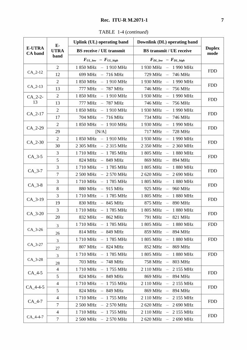
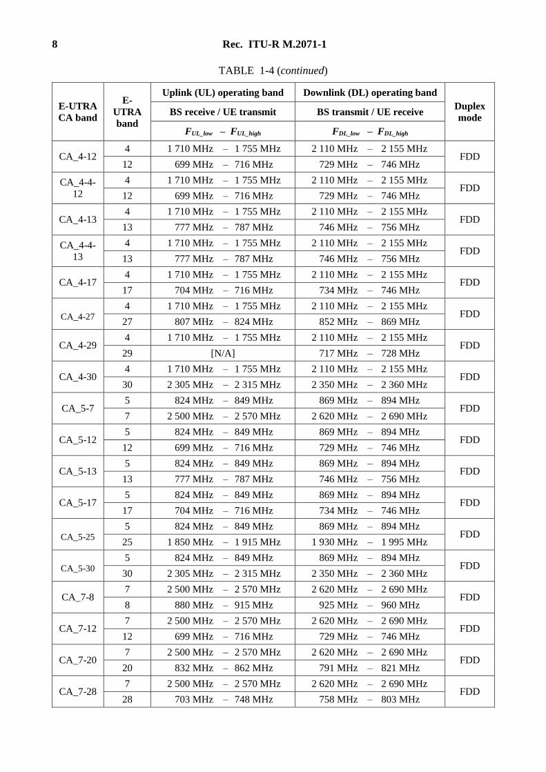
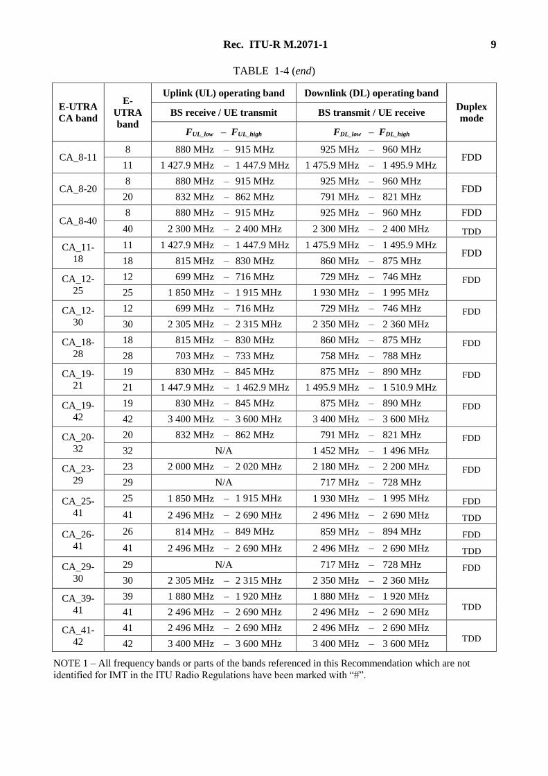
The unwanted emission limits defined in the present Annex are for E-UTRA MS operating at least
one of the inter-band CA combinations in Table 1-4:
6 Rec. ITU-R M.2071-1
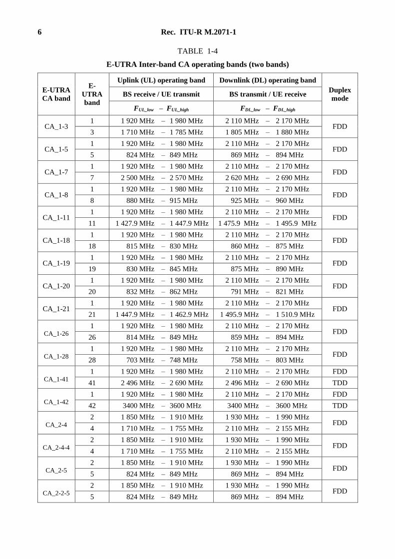
TABLE 1-4
E-UTRA Inter-band CA operating bands (two bands)
E-UTRA
CA band
E-
UTRA
band
Uplink (UL) operating band Downlink (DL) operating band
Duplex
mode BS receive / UE transmit BS transmit / UE receive
FUL_low – FUL_high FDL_low – FDL_high
CA_1-3 1 1 920 MHz – 1 980 MHz 2 110 MHz – 2 170 MHz
FDD 3 1 710 MHz – 1 785 MHz 1 805 MHz – 1 880 MHz
CA_1-5 1 1 920 MHz – 1 980 MHz 2 110 MHz – 2 170 MHz
FDD 5 824 MHz – 849 MHz 869 MHz – 894 MHz
CA_1-7 1 1 920 MHz – 1 980 MHz 2 110 MHz – 2 170 MHz
FDD 7 2 500 MHz – 2 570 MHz 2 620 MHz – 2 690 MHz
CA_1-8 1 1 920 MHz – 1 980 MHz 2 110 MHz – 2 170 MHz
FDD 8 880 MHz – 915 MHz 925 MHz – 960 MHz
CA_1-11 1 1 920 MHz – 1 980 MHz 2 110 MHz – 2 170 MHz
FDD 11 1 427.9 MHz – 1 447.9 MHz 1 475.9 MHz – 1 495.9 MHz
CA_1-18 1 1 920 MHz – 1 980 MHz 2 110 MHz – 2 170 MHz
FDD 18 815 MHz – 830 MHz 860 MHz – 875 MHz
CA_1-19 1 1 920 MHz – 1 980 MHz 2 110 MHz – 2 170 MHz
FDD 19 830 MHz – 845 MHz 875 MHz – 890 MHz
CA_1-20 1 1 920 MHz – 1 980 MHz 2 110 MHz – 2 170 MHz
FDD 20 832 MHz – 862 MHz 791 MHz – 821 MHz
CA_1-21 1 1 920 MHz – 1 980 MHz 2 110 MHz – 2 170 MHz
FDD 21 1 447.9 MHz – 1 462.9 MHz 1 495.9 MHz – 1 510.9 MHz
CA_1-26 1 1 920 MHz – 1 980 MHz 2 110 MHz – 2 170 MHz
FDD 26 814 MHz – 849 MHz 859 MHz – 894 MHz
CA_1-28 1 1 920 MHz – 1 980 MHz 2 110 MHz – 2 170 MHz
FDD 28 703 MHz – 748 MHz 758 MHz – 803 MHz
CA_1-41 1 1 920 MHz – 1 980 MHz 2 110 MHz – 2 170 MHz FDD
41 2 496 MHz – 2 690 MHz 2 496 MHz – 2 690 MHz TDD
CA_1-42 1 1 920 MHz – 1 980 MHz 2 110 MHz – 2 170 MHz FDD
42 3400 MHz – 3600 MHz 3400 MHz – 3600 MHz TDD
CA_2-4 2 1 850 MHz – 1 910 MHz 1 930 MHz – 1 990 MHz
FDD 4 1 710 MHz – 1 755 MHz 2 110 MHz – 2 155 MHz
CA_2-4-4 2 1 850 MHz – 1 910 MHz 1 930 MHz – 1 990 MHz
FDD 4 1 710 MHz – 1 755 MHz 2 110 MHz – 2 155 MHz
CA_2-5 2 1 850 MHz – 1 910 MHz 1 930 MHz – 1 990 MHz
FDD 5 824 MHz – 849 MHz 869 MHz – 894 MHz
CA_2-2-5 2 1 850 MHz – 1 910 MHz 1 930 MHz – 1 990 MHz
FDD 5 824 MHz – 849 MHz 869 MHz – 894 MHz
Rec. ITU-R M.2071-1 7
TABLE 1-4 (continued)
E-UTRA
CA band
E-
UTRA
band
Uplink (UL) operating band Downlink (DL) operating band
Duplex
mode BS receive / UE transmit BS transmit / UE receive
FUL_low – FUL_high FDL_low – FDL_high
CA_2-12 2 1 850 MHz – 1 910 MHz 1 930 MHz – 1 990 MHz
FDD 12 699 MHz – 716 MHz 729 MHz – 746 MHz
CA_2-13 2 1 850 MHz – 1 910 MHz 1 930 MHz – 1 990 MHz
FDD 13 777 MHz – 787 MHz 746 MHz – 756 MHz
CA_2-2-
13
2 1 850 MHz – 1 910 MHz 1 930 MHz – 1 990 MHz FDD
13 777 MHz – 787 MHz 746 MHz – 756 MHz
CA_2-17 2 1 850 MHz – 1 910 MHz 1 930 MHz – 1 990 MHz
FDD 17 704 MHz – 716 MHz 734 MHz – 746 MHz
CA_2-29 2 1 850 MHz – 1 910 MHz 1 930 MHz – 1 990 MHz
FDD 29 [N/A] 717 MHz – 728 MHz
CA_2-30 2 1 850 MHz – 1 910 MHz 1 930 MHz – 1 990 MHz
FDD 30 2 305 MHz – 2 315 MHz 2 350 MHz – 2 360 MHz
CA_3-5 3 1 710 MHz – 1 785 MHz 1 805 MHz – 1 880 MHz
FDD 5 824 MHz – 849 MHz 869 MHz – 894 MHz
CA_3-7 3 1 710 MHz – 1 785 MHz 1 805 MHz – 1 880 MHz
FDD 7 2 500 MHz – 2 570 MHz 2 620 MHz – 2 690 MHz
CA_3-8 3 1 710 MHz – 1 785 MHz 1 805 MHz – 1 880 MHz
FDD 8 880 MHz – 915 MHz 925 MHz – 960 MHz
CA_3-19 3 1 710 MHz – 1 785 MHz 1 805 MHz – 1 880 MHz
FDD 19 830 MHz – 845 MHz 875 MHz – 890 MHz
CA_3-20 3 1 710 MHz – 1 785 MHz 1 805 MHz – 1 880 MHz
FDD 20 832 MHz – 862 MHz 791 MHz – 821 MHz
CA_3-26 3 1 710 MHz – 1 785 MHz 1 805 MHz – 1 880 MHz FDD
26 814 MHz – 849 MHz 859 MHz – 894 MHz
CA_3-27 3 1 710 MHz – 1 785 MHz 1 805 MHz – 1 880 MHz FDD
27 807 MHz – 824 MHz 852 MHz – 869 MHz
CA_3-28 3 1 710 MHz – 1 785 MHz 1 805 MHz – 1 880 MHz FDD
28 703 MHz – 748 MHz 758 MHz – 803 MHz
CA_4-5 4 1 710 MHz – 1 755 MHz 2 110 MHz – 2 155 MHz
FDD 5 824 MHz – 849 MHz 869 MHz – 894 MHz
CA_4-4-5 4 1 710 MHz – 1 755 MHz 2 110 MHz – 2 155 MHz
FDD 5 824 MHz – 849 MHz 869 MHz – 894 MHz
CA_4-7 4 1 710 MHz – 1 755 MHz 2 110 MHz – 2 155 MHz
FDD 7 2 500 MHz – 2 570 MHz 2 620 MHz – 2 690 MHz
CA_4-4-7 4 1 710 MHz – 1 755 MHz 2 110 MHz – 2 155 MHz
FDD 7 2 500 MHz – 2 570 MHz 2 620 MHz – 2 690 MHz
8 Rec. ITU-R M.2071-1
TABLE 1-4 (continued)
E-UTRA
CA band
E-
UTRA
band
Uplink (UL) operating band Downlink (DL) operating band
Duplex
mode BS receive / UE transmit BS transmit / UE receive
FUL_low – FUL_high FDL_low – FDL_high
CA_4-12 4 1 710 MHz – 1 755 MHz 2 110 MHz – 2 155 MHz
FDD 12 699 MHz – 716 MHz 729 MHz – 746 MHz
CA_4-4-
12
4 1 710 MHz – 1 755 MHz 2 110 MHz – 2 155 MHz FDD
12 699 MHz – 716 MHz 729 MHz – 746 MHz
CA_4-13 4 1 710 MHz – 1 755 MHz 2 110 MHz – 2 155 MHz
FDD 13 777 MHz – 787 MHz 746 MHz – 756 MHz
CA_4-4-
13
4 1 710 MHz – 1 755 MHz 2 110 MHz – 2 155 MHz FDD
13 777 MHz – 787 MHz 746 MHz – 756 MHz
CA_4-17 4 1 710 MHz – 1 755 MHz 2 110 MHz – 2 155 MHz
FDD 17 704 MHz – 716 MHz 734 MHz – 746 MHz
CA_4-27 4 1 710 MHz – 1 755 MHz 2 110 MHz – 2 155 MHz
FDD 27 807 MHz – 824 MHz 852 MHz – 869 MHz
CA_4-29 4 1 710 MHz – 1 755 MHz 2 110 MHz – 2 155 MHz
FDD 29 [N/A] 717 MHz – 728 MHz
CA_4-30 4 1 710 MHz – 1 755 MHz 2 110 MHz – 2 155 MHz
FDD 30 2 305 MHz – 2 315 MHz 2 350 MHz – 2 360 MHz
CA_5-7 5 824 MHz – 849 MHz 869 MHz – 894 MHz
FDD 7 2 500 MHz – 2 570 MHz 2 620 MHz – 2 690 MHz
CA_5-12 5 824 MHz – 849 MHz 869 MHz – 894 MHz
FDD 12 699 MHz – 716 MHz 729 MHz – 746 MHz
CA_5-13 5 824 MHz – 849 MHz 869 MHz – 894 MHz
FDD 13 777 MHz – 787 MHz 746 MHz – 756 MHz
CA_5-17 5 824 MHz – 849 MHz 869 MHz – 894 MHz
FDD 17 704 MHz – 716 MHz 734 MHz – 746 MHz
CA_5-25 5 824 MHz – 849 MHz 869 MHz – 894 MHz
FDD 25 1 850 MHz – 1 915 MHz 1 930 MHz – 1 995 MHz
CA_5-30 5 824 MHz – 849 MHz 869 MHz – 894 MHz
FDD 30 2 305 MHz – 2 315 MHz 2 350 MHz – 2 360 MHz
CA_7-8 7 2 500 MHz – 2 570 MHz 2 620 MHz – 2 690 MHz
FDD 8 880 MHz – 915 MHz 925 MHz – 960 MHz
CA_7-12 7 2 500 MHz – 2 570 MHz 2 620 MHz – 2 690 MHz
FDD 12 699 MHz – 716 MHz 729 MHz – 746 MHz
CA_7-20 7 2 500 MHz – 2 570 MHz 2 620 MHz – 2 690 MHz
FDD 20 832 MHz – 862 MHz 791 MHz – 821 MHz
CA_7-28 7 2 500 MHz – 2 570 MHz 2 620 MHz – 2 690 MHz
FDD 28 703 MHz – 748 MHz 758 MHz – 803 MHz
Rec. ITU-R M.2071-1 9
TABLE 1-4 (end)
E-UTRA
CA band
E-
UTRA
band
Uplink (UL) operating band Downlink (DL) operating band
Duplex
mode BS receive / UE transmit BS transmit / UE receive
FUL_low – FUL_high FDL_low – FDL_high
CA_8-11 8 880 MHz – 915 MHz 925 MHz – 960 MHz
FDD 11 1 427.9 MHz – 1 447.9 MHz 1 475.9 MHz – 1 495.9 MHz
CA_8-20 8 880 MHz – 915 MHz 925 MHz – 960 MHz
FDD 20 832 MHz – 862 MHz 791 MHz – 821 MHz
CA_8-40 8 880 MHz – 915 MHz 925 MHz – 960 MHz FDD
40 2 300 MHz – 2 400 MHz 2 300 MHz – 2 400 MHz TDD
CA_11-
18
11 1 427.9 MHz – 1 447.9 MHz 1 475.9 MHz – 1 495.9 MHz FDD
18 815 MHz – 830 MHz 860 MHz – 875 MHz
CA_12-
25
12 699 MHz – 716 MHz 729 MHz – 746 MHz FDD
25 1 850 MHz – 1 915 MHz 1 930 MHz – 1 995 MHz
CA_12-
30
12 699 MHz – 716 MHz 729 MHz – 746 MHz FDD
30 2 305 MHz – 2 315 MHz 2 350 MHz – 2 360 MHz
CA_18-
28
18 815 MHz – 830 MHz 860 MHz – 875 MHz FDD
28 703 MHz – 733 MHz 758 MHz – 788 MHz
CA_19-
21
19 830 MHz – 845 MHz 875 MHz – 890 MHz FDD
21 1 447.9 MHz – 1 462.9 MHz 1 495.9 MHz – 1 510.9 MHz
CA_19-
42
19 830 MHz – 845 MHz 875 MHz – 890 MHz FDD
42 3 400 MHz – 3 600 MHz 3 400 MHz – 3 600 MHz
CA_20-
32
20 832 MHz – 862 MHz 791 MHz – 821 MHz FDD
32 N/A 1 452 MHz – 1 496 MHz
CA_23-
29
23 2 000 MHz – 2 020 MHz 2 180 MHz – 2 200 MHz FDD
29 N/A 717 MHz – 728 MHz
CA_25-
41
25 1 850 MHz – 1 915 MHz 1 930 MHz – 1 995 MHz FDD
41 2 496 MHz – 2 690 MHz 2 496 MHz – 2 690 MHz TDD
CA_26-
41
26 814 MHz – 849 MHz 859 MHz – 894 MHz FDD
41 2 496 MHz – 2 690 MHz 2 496 MHz – 2 690 MHz TDD
CA_29-
30
29 N/A 717 MHz – 728 MHz FDD
30 2 305 MHz – 2 315 MHz 2 350 MHz – 2 360 MHz
CA_39-
41
39 1 880 MHz – 1 920 MHz 1 880 MHz – 1 920 MHz TDD
41 2 496 MHz – 2 690 MHz 2 496 MHz – 2 690 MHz
CA_41-
42
41 2 496 MHz – 2 690 MHz 2 496 MHz – 2 690 MHz TDD
42 3 400 MHz – 3 600 MHz 3 400 MHz – 3 600 MHz
NOTE 1 – All frequency bands or parts of the bands referenced in this Recommendation which are not
identified for IMT in the ITU Radio Regulations have been marked with “#”.
10 Rec. ITU-R M.2071-1
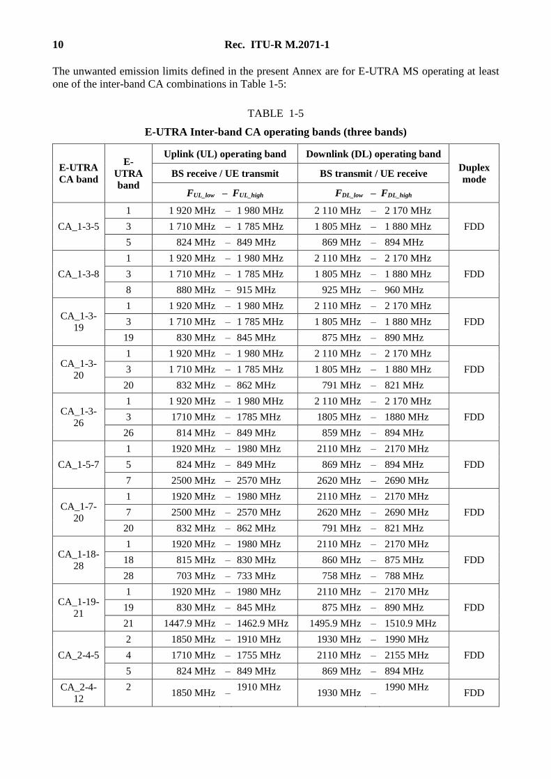
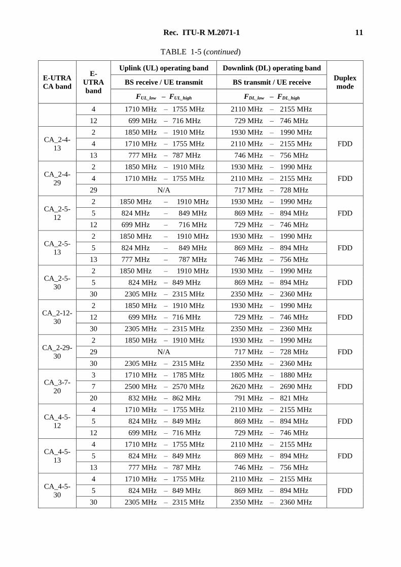
The unwanted emission limits defined in the present Annex are for E-UTRA MS operating at least
one of the inter-band CA combinations in Table 1-5:
TABLE 1-5
E-UTRA Inter-band CA operating bands (three bands)
E-UTRA
CA band
E-
UTRA
band
Uplink (UL) operating band Downlink (DL) operating band
Duplex
mode BS receive / UE transmit BS transmit / UE receive
FUL_low – FUL_high FDL_low – FDL_high
CA_1-3-5
1 1 920 MHz – 1 980 MHz 2 110 MHz – 2 170 MHz
FDD 3 1 710 MHz – 1 785 MHz 1 805 MHz – 1 880 MHz
5 824 MHz – 849 MHz 869 MHz – 894 MHz
CA_1-3-8
1 1 920 MHz – 1 980 MHz 2 110 MHz – 2 170 MHz
FDD 3 1 710 MHz – 1 785 MHz 1 805 MHz – 1 880 MHz
8 880 MHz – 915 MHz 925 MHz – 960 MHz
CA_1-3-
19
1 1 920 MHz – 1 980 MHz 2 110 MHz – 2 170 MHz
FDD 3 1 710 MHz – 1 785 MHz 1 805 MHz – 1 880 MHz
19 830 MHz – 845 MHz 875 MHz – 890 MHz
CA_1-3-
20
1 1 920 MHz – 1 980 MHz 2 110 MHz – 2 170 MHz
FDD 3 1 710 MHz – 1 785 MHz 1 805 MHz – 1 880 MHz
20 832 MHz – 862 MHz 791 MHz – 821 MHz
CA_1-3-
26
1 1 920 MHz – 1 980 MHz 2 110 MHz – 2 170 MHz
FDD 3 1710 MHz – 1785 MHz 1805 MHz – 1880 MHz
26 814 MHz – 849 MHz 859 MHz – 894 MHz
CA_1-5-7
1 1920 MHz – 1980 MHz 2110 MHz – 2170 MHz
FDD 5 824 MHz – 849 MHz 869 MHz – 894 MHz
7 2500 MHz – 2570 MHz 2620 MHz – 2690 MHz
CA_1-7-
20
1 1920 MHz – 1980 MHz 2110 MHz – 2170 MHz
FDD 7 2500 MHz – 2570 MHz 2620 MHz – 2690 MHz
20 832 MHz – 862 MHz 791 MHz – 821 MHz
CA_1-18-
28
1 1920 MHz – 1980 MHz 2110 MHz – 2170 MHz
FDD 18 815 MHz – 830 MHz 860 MHz – 875 MHz
28 703 MHz – 733 MHz 758 MHz – 788 MHz
CA_1-19-
21
1 1920 MHz – 1980 MHz 2110 MHz – 2170 MHz
FDD 19 830 MHz – 845 MHz 875 MHz – 890 MHz
21 1447.9 MHz – 1462.9 MHz 1495.9 MHz – 1510.9 MHz
CA_2-4-5
2 1850 MHz – 1910 MHz 1930 MHz – 1990 MHz
FDD 4 1710 MHz – 1755 MHz 2110 MHz – 2155 MHz
5 824 MHz – 849 MHz 869 MHz – 894 MHz
CA_2-4-
12
2 1850 MHz –
1910 MHz 1930 MHz –
1990 MHz FDD
Rec. ITU-R M.2071-1 11
TABLE 1-5 (continued)
E-UTRA
CA band
E-
UTRA
band
Uplink (UL) operating band Downlink (DL) operating band
Duplex
mode BS receive / UE transmit BS transmit / UE receive
FUL_low – FUL_high FDL_low – FDL_high
4 1710 MHz – 1755 MHz 2110 MHz – 2155 MHz
12 699 MHz – 716 MHz 729 MHz – 746 MHz
CA_2-4-
13
2 1850 MHz – 1910 MHz 1930 MHz – 1990 MHz
FDD 4 1710 MHz – 1755 MHz 2110 MHz – 2155 MHz
13 777 MHz – 787 MHz 746 MHz – 756 MHz
CA_2-4-
29
2 1850 MHz – 1910 MHz 1930 MHz – 1990 MHz
FDD 4 1710 MHz – 1755 MHz 2110 MHz – 2155 MHz
29 N/A 717 MHz – 728 MHz
CA_2-5-
12
2 1850 MHz – 1910 MHz 1930 MHz – 1990 MHz
FDD 5 824 MHz – 849 MHz 869 MHz – 894 MHz
12 699 MHz – 716 MHz 729 MHz – 746 MHz
CA_2-5-
13
2 1850 MHz – 1910 MHz 1930 MHz – 1990 MHz
FDD 5 824 MHz – 849 MHz 869 MHz – 894 MHz
13 777 MHz – 787 MHz 746 MHz – 756 MHz
CA_2-5-
30
2 1850 MHz – 1910 MHz 1930 MHz – 1990 MHz
FDD 5 824 MHz – 849 MHz 869 MHz – 894 MHz
30 2305 MHz – 2315 MHz 2350 MHz – 2360 MHz
CA_2-12-
30
2 1850 MHz – 1910 MHz 1930 MHz – 1990 MHz
FDD 12 699 MHz – 716 MHz 729 MHz – 746 MHz
30 2305 MHz – 2315 MHz 2350 MHz – 2360 MHz
CA_2-29-
30
2 1850 MHz – 1910 MHz 1930 MHz – 1990 MHz
FDD 29 N/A 717 MHz – 728 MHz
30 2305 MHz – 2315 MHz 2350 MHz – 2360 MHz
CA_3-7-
20
3 1710 MHz – 1785 MHz 1805 MHz – 1880 MHz
FDD 7 2500 MHz – 2570 MHz 2620 MHz – 2690 MHz
20 832 MHz – 862 MHz 791 MHz – 821 MHz
CA_4-5-
12
4 1710 MHz – 1755 MHz 2110 MHz – 2155 MHz
FDD 5 824 MHz – 849 MHz 869 MHz – 894 MHz
12 699 MHz – 716 MHz 729 MHz – 746 MHz
CA_4-5-
13
4 1710 MHz – 1755 MHz 2110 MHz – 2155 MHz
FDD 5 824 MHz – 849 MHz 869 MHz – 894 MHz
13 777 MHz – 787 MHz 746 MHz – 756 MHz
CA_4-5-
30
4 1710 MHz – 1755 MHz 2110 MHz – 2155 MHz
FDD 5 824 MHz – 849 MHz 869 MHz – 894 MHz
30 2305 MHz – 2315 MHz 2350 MHz – 2360 MHz
12 Rec. ITU-R M.2071-1
TABLE 1-5 (end)
E-UTRA
CA band
E-
UTR
A
band
Uplink (UL) operating band Downlink (DL) operating band
Duplex
mode BS receive / UE transmit BS transmit / UE receive
FUL_low – FUL_high FDL_low – FDL_high
CA_4-7-12
4 1710 MHz – 1755 MHz 2110 MHz – 2155 MHz
FDD 7 2500 MHz – 2570 MHz 2620 MHz – 2690 MHz
12 699 MHz – 716 MHz 729 MHz – 746 MHz
CA_4-12-30
4 1710 MHz – 1755 MHz 2110 MHz – 2155 MHz
FDD 12 699 MHz – 716 MHz 729 MHz – 746 MHz
30 2305 MHz – 2315 MHz 2350 MHz – 2360 MHz
CA_4-29-30
4 1710 MHz – 1755 MHz 2110 MHz – 2155 MHz
FDD 29 N/A 717 MHz – 728 MHz
30 2305 MHz – 2315 MHz 2350 MHz – 2360 MHz
CA_7-8-20
7 2500 MHz – 2570 MHz 2620 MHz – 2690 MHz
FDD 8 880 MHz – 915 MHz 925 MHz – 960 MHz
20 832 MHz – 862 MHz 791 MHz – 821 MHz
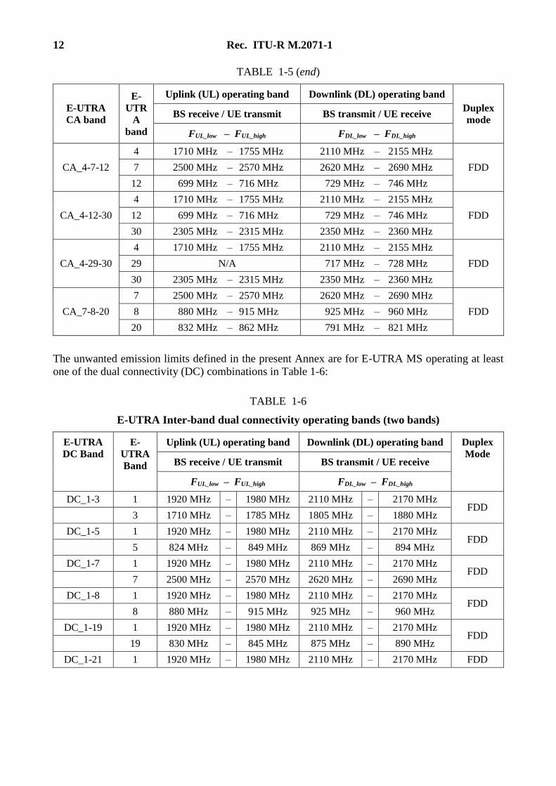
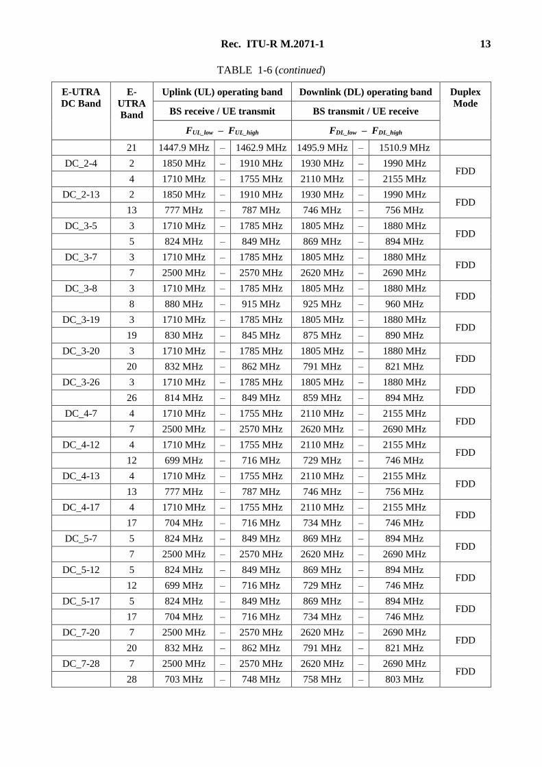
The unwanted emission limits defined in the present Annex are for E-UTRA MS operating at least
one of the dual connectivity (DC) combinations in Table 1-6:
TABLE 1-6
E-UTRA Inter-band dual connectivity operating bands (two bands)
E-UTRA
DC Band
E-
UTRA
Band
Uplink (UL) operating band Downlink (DL) operating band Duplex
Mode BS receive / UE transmit BS transmit / UE receive
FUL_low – FUL_high FDL_low – FDL_high
DC_1-3 1 1920 MHz – 1980 MHz 2110 MHz – 2170 MHz FDD
3 1710 MHz – 1785 MHz 1805 MHz – 1880 MHz
DC_1-5 1 1920 MHz – 1980 MHz 2110 MHz – 2170 MHz FDD
5 824 MHz – 849 MHz 869 MHz – 894 MHz
DC_1-7 1 1920 MHz – 1980 MHz 2110 MHz – 2170 MHz FDD
7 2500 MHz – 2570 MHz 2620 MHz – 2690 MHz
DC_1-8 1 1920 MHz – 1980 MHz 2110 MHz – 2170 MHz FDD
8 880 MHz – 915 MHz 925 MHz – 960 MHz
DC_1-19 1 1920 MHz – 1980 MHz 2110 MHz – 2170 MHz FDD
19 830 MHz – 845 MHz 875 MHz – 890 MHz
DC_1-21 1 1920 MHz – 1980 MHz 2110 MHz – 2170 MHz FDD
Rec. ITU-R M.2071-1 13
TABLE 1-6 (continued)
E-UTRA
DC Band
E-
UTRA
Band
Uplink (UL) operating band Downlink (DL) operating band Duplex
Mode BS receive / UE transmit BS transmit / UE receive
FUL_low – FUL_high FDL_low – FDL_high
21 1447.9 MHz – 1462.9 MHz 1495.9 MHz – 1510.9 MHz
DC_2-4 2 1850 MHz – 1910 MHz 1930 MHz – 1990 MHz FDD
4 1710 MHz – 1755 MHz 2110 MHz – 2155 MHz
DC_2-13 2 1850 MHz – 1910 MHz 1930 MHz – 1990 MHz FDD
13 777 MHz – 787 MHz 746 MHz – 756 MHz
DC_3-5 3 1710 MHz – 1785 MHz 1805 MHz – 1880 MHz FDD
5 824 MHz – 849 MHz 869 MHz – 894 MHz
DC_3-7 3 1710 MHz – 1785 MHz 1805 MHz – 1880 MHz FDD
7 2500 MHz – 2570 MHz 2620 MHz – 2690 MHz
DC_3-8 3 1710 MHz – 1785 MHz 1805 MHz – 1880 MHz FDD
8 880 MHz – 915 MHz 925 MHz – 960 MHz
DC_3-19 3 1710 MHz – 1785 MHz 1805 MHz – 1880 MHz FDD
19 830 MHz – 845 MHz 875 MHz – 890 MHz
DC_3-20 3 1710 MHz – 1785 MHz 1805 MHz – 1880 MHz FDD
20 832 MHz – 862 MHz 791 MHz – 821 MHz
DC_3-26 3 1710 MHz – 1785 MHz 1805 MHz – 1880 MHz FDD
26 814 MHz – 849 MHz 859 MHz – 894 MHz
DC_4-7 4 1710 MHz – 1755 MHz 2110 MHz – 2155 MHz FDD
7 2500 MHz – 2570 MHz 2620 MHz – 2690 MHz
DC_4-12 4 1710 MHz – 1755 MHz 2110 MHz – 2155 MHz FDD
12 699 MHz – 716 MHz 729 MHz – 746 MHz
DC_4-13 4 1710 MHz – 1755 MHz 2110 MHz – 2155 MHz FDD
13 777 MHz – 787 MHz 746 MHz – 756 MHz
DC_4-17 4 1710 MHz – 1755 MHz 2110 MHz – 2155 MHz FDD
17 704 MHz – 716 MHz 734 MHz – 746 MHz
DC_5-7 5 824 MHz – 849 MHz 869 MHz – 894 MHz FDD
7 2500 MHz – 2570 MHz 2620 MHz – 2690 MHz
DC_5-12 5 824 MHz – 849 MHz 869 MHz – 894 MHz FDD
12 699 MHz – 716 MHz 729 MHz – 746 MHz
DC_5-17 5 824 MHz – 849 MHz 869 MHz – 894 MHz FDD
17 704 MHz – 716 MHz 734 MHz – 746 MHz
DC_7-20 7 2500 MHz – 2570 MHz 2620 MHz – 2690 MHz FDD
20 832 MHz – 862 MHz 791 MHz – 821 MHz
DC_7-28 7 2500 MHz – 2570 MHz 2620 MHz – 2690 MHz FDD
28 703 MHz – 748 MHz 758 MHz – 803 MHz
14 Rec. ITU-R M.2071-1
TABLE 1-6 (end)
E-UTRA
DC Band
E-
UTRA
Band
Uplink (UL) operating band Downlink (DL) operating band Duplex
Mode BS receive / UE transmit BS transmit / UE receive
FUL_low – FUL_high FDL_low – FDL_high
DC_19-21 19 830 MHz – 845 MHz 875 MHz – 890 MHz FDD
21 1447.9 MHz – 1462.9 MHz 1495.9 MHz – 1510.9 MHz
DC_39-41 39 1880 MHz – 1920 MHz 1880 MHz – 1920 MHz TDD
41 2496 MHz – 2690 MHz 2496 MHz – 2690 MHz
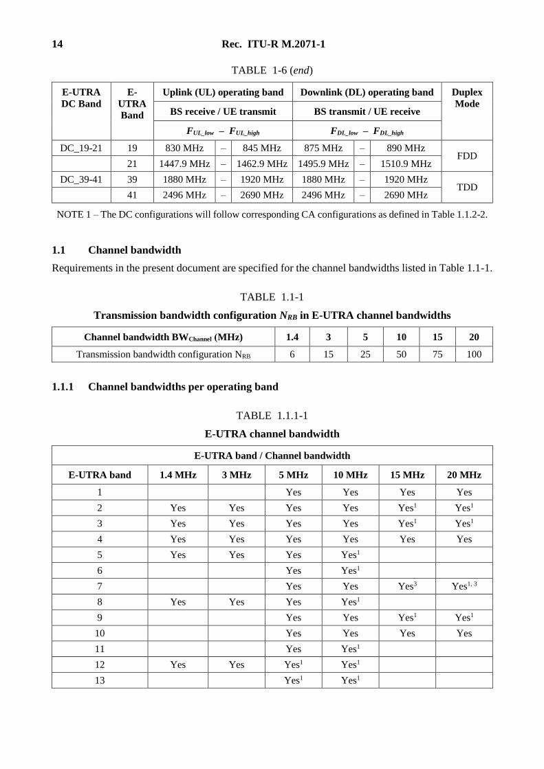
NOTE 1 – The DC configurations will follow corresponding CA configurations as defined in Table 1.1.2-2.
1.1 Channel bandwidth
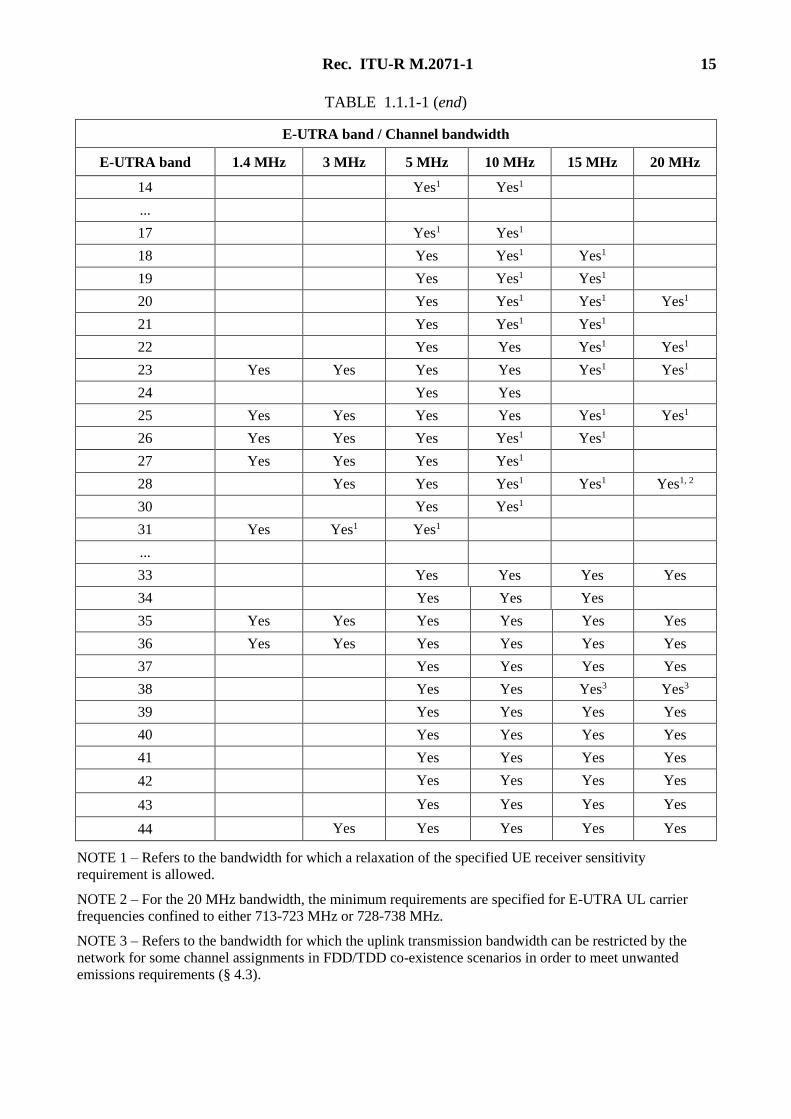
Requirements in the present document are specified for the channel bandwidths listed in Table 1.1-1.
TABLE 1.1-1
Transmission bandwidth configuration NRB in E-UTRA channel bandwidths
Channel bandwidth BWChannel (MHz) 1.4 3 5 10 15 20
Transmission bandwidth configuration NRB 6 15 25 50 75 100
1.1.1 Channel bandwidths per operating band
TABLE 1.1.1-1
E-UTRA channel bandwidth
E-UTRA band / Channel bandwidth
E-UTRA band 1.4 MHz 3 MHz 5 MHz 10 MHz 15 MHz 20 MHz
1 Yes Yes Yes Yes
2 Yes Yes Yes Yes Yes1 Yes1
3 Yes Yes Yes Yes Yes1 Yes1
4 Yes Yes Yes Yes Yes Yes
5 Yes Yes Yes Yes1
6 Yes Yes1
7 Yes Yes Yes3 Yes1, 3
8 Yes Yes Yes Yes1
9 Yes Yes Yes1 Yes1
10 Yes Yes Yes Yes
11 Yes Yes1
12 Yes Yes Yes1 Yes1
13 Yes1 Yes1
Rec. ITU-R M.2071-1 15
TABLE 1.1.1-1 (end)
E-UTRA band / Channel bandwidth
E-UTRA band 1.4 MHz 3 MHz 5 MHz 10 MHz 15 MHz 20 MHz
14 Yes1 Yes1
...
17 Yes1 Yes1
18 Yes Yes1 Yes1
19 Yes Yes1 Yes1
20 Yes Yes1 Yes1 Yes1
21 Yes Yes1 Yes1
22 Yes Yes Yes1 Yes1
23 Yes Yes Yes Yes Yes1 Yes1
24 Yes Yes
25 Yes Yes Yes Yes Yes1 Yes1
26 Yes Yes Yes Yes1 Yes1
27 Yes Yes Yes Yes1
28 Yes Yes Yes1 Yes1 Yes1, 2
30 Yes Yes1
31 Yes Yes1 Yes1
...
33 Yes Yes Yes Yes
34 Yes Yes Yes
35 Yes Yes Yes Yes Yes Yes
36 Yes Yes Yes Yes Yes Yes
37 Yes Yes Yes Yes
38 Yes Yes Yes3 Yes3
39 Yes Yes Yes Yes
40 Yes Yes Yes Yes
41 Yes Yes Yes Yes
42 Yes Yes Yes Yes
43 Yes Yes Yes Yes
44 Yes Yes Yes Yes Yes
NOTE 1 – Refers to the bandwidth for which a relaxation of the specified UE receiver sensitivity
requirement is allowed.
NOTE 2 – For the 20 MHz bandwidth, the minimum requirements are specified for E-UTRA UL carrier
frequencies confined to either 713-723 MHz or 728-738 MHz.
NOTE 3 – Refers to the bandwidth for which the uplink transmission bandwidth can be restricted by the
network for some channel assignments in FDD/TDD co-existence scenarios in order to meet unwanted
emissions requirements (§ 4.3).
16 Rec. ITU-R M.2071-1
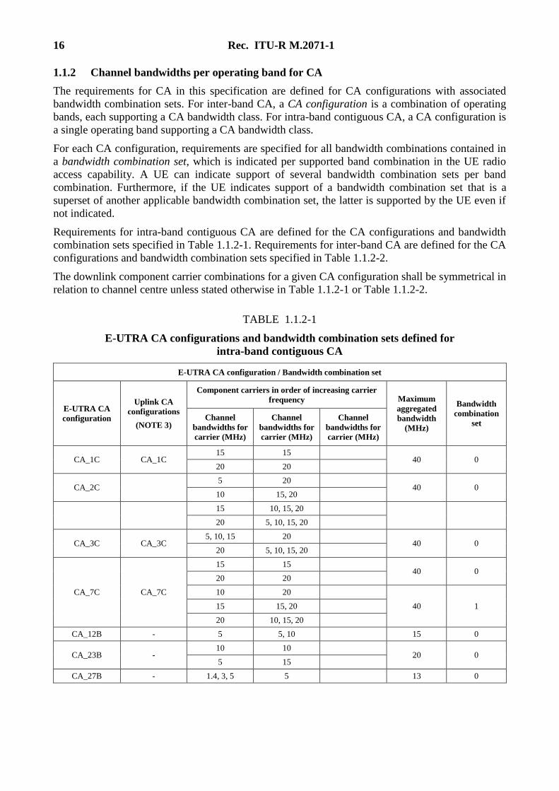
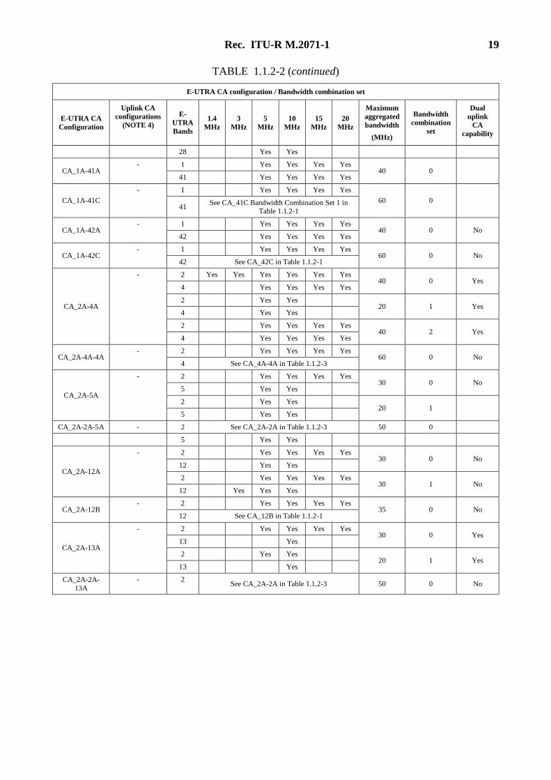
1.1.2 Channel bandwidths per operating band for CA
The requirements for CA in this specification are defined for CA configurations with associated
bandwidth combination sets. For inter-band CA, a CA configuration is a combination of operating
bands, each supporting a CA bandwidth class. For intra-band contiguous CA, a CA configuration is
a single operating band supporting a CA bandwidth class.
For each CA configuration, requirements are specified for all bandwidth combinations contained in
a bandwidth combination set, which is indicated per supported band combination in the UE radio
access capability. A UE can indicate support of several bandwidth combination sets per band
combination. Furthermore, if the UE indicates support of a bandwidth combination set that is a
superset of another applicable bandwidth combination set, the latter is supported by the UE even if
not indicated.
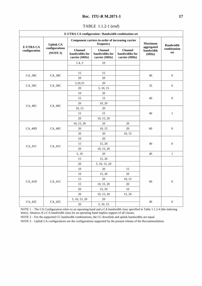
Requirements for intra-band contiguous CA are defined for the CA configurations and bandwidth
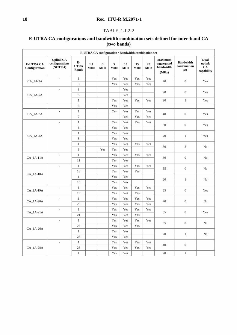
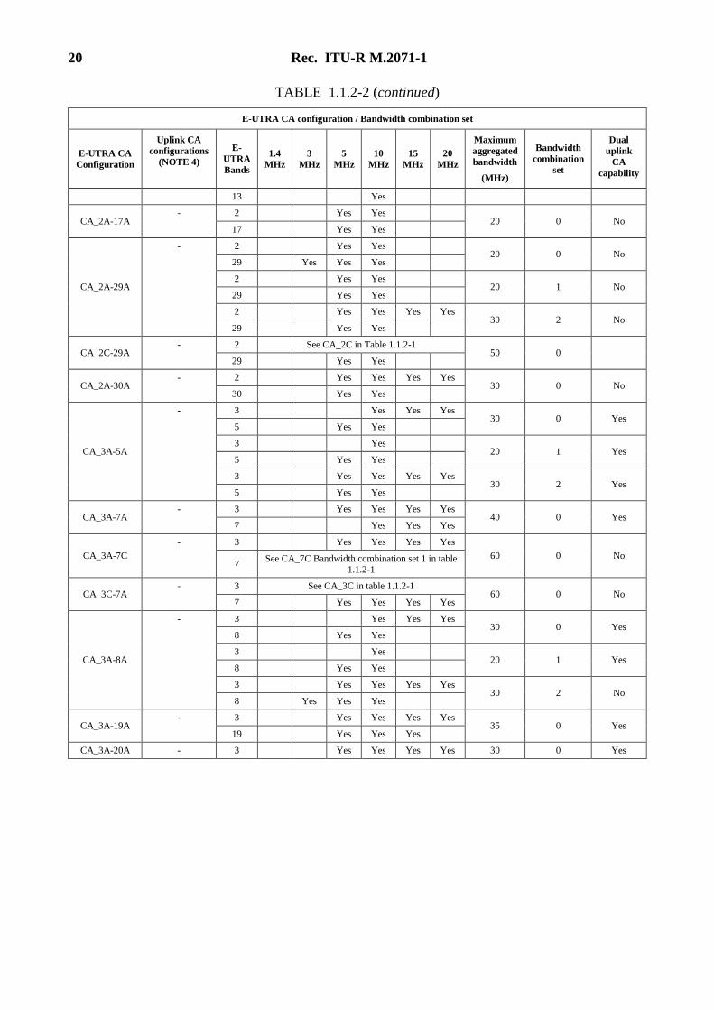
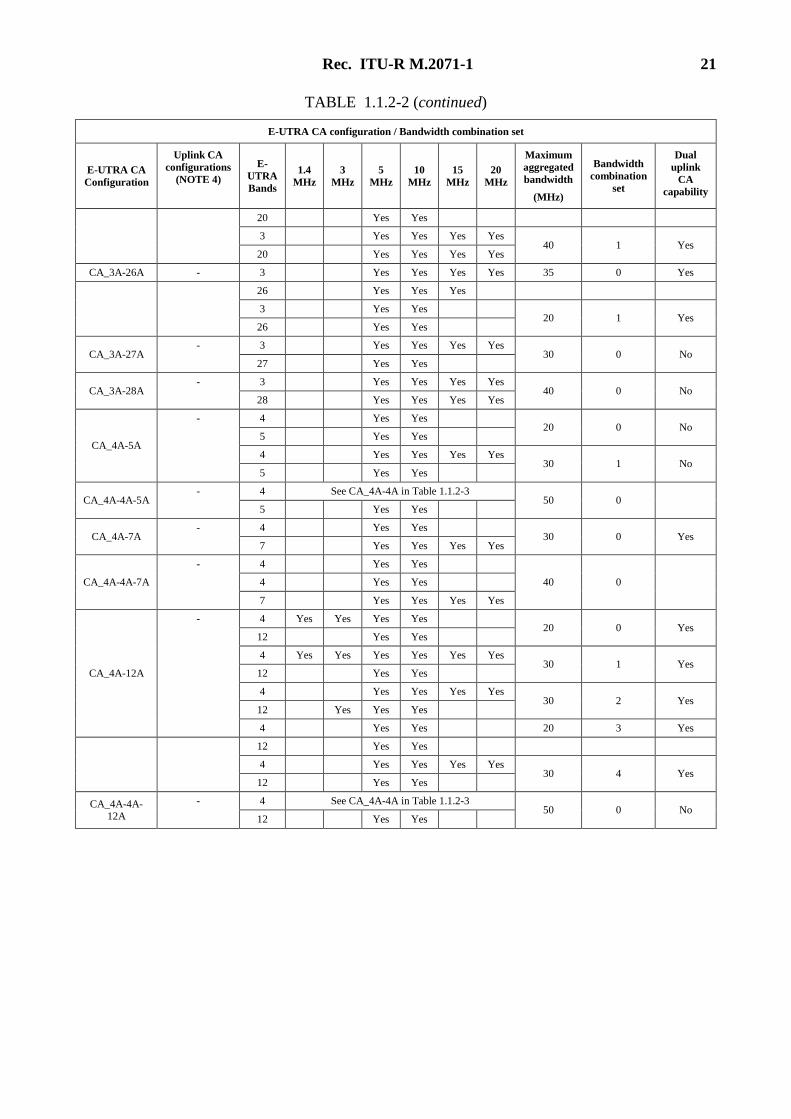
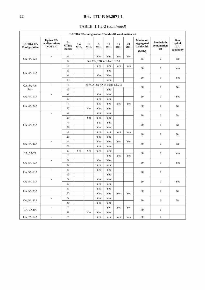
combination sets specified in Table 1.1.2-1. Requirements for inter-band CA are defined for the CA
configurations and bandwidth combination sets specified in Table 1.1.2-2.
The downlink component carrier combinations for a given CA configuration shall be symmetrical in
relation to channel centre unless stated otherwise in Table 1.1.2-1 or Table 1.1.2-2.
TABLE 1.1.2-1
E-UTRA CA configurations and bandwidth combination sets defined for
intra-band contiguous CA
E-UTRA CA configuration / Bandwidth combination set
E-UTRA CA
configuration
Uplink CA
configurations
(NOTE 3)
Component carriers in order of increasing carrier
frequency Maximum
aggregated
bandwidth
(MHz)
Bandwidth
combination
set Channel
bandwidths for
carrier (MHz)
Channel
bandwidths for
carrier (MHz)
Channel
bandwidths for
carrier (MHz)
CA_1C CA_1C 15 15
40 0 20 20
CA_2C 5 20
40 0 10 15, 20
15 10, 15, 20
20 5, 10, 15, 20
CA_3C CA_3C 5, 10, 15 20
40 0 20 5, 10, 15, 20
CA_7C CA_7C
15 15 40 0
20 20
10 20
40 1 15 15, 20
20 10, 15, 20
CA_12B - 5 5, 10 15 0
CA_23B - 10 10
20 0 5 15
CA_27B - 1.4, 3, 5 5 13 0
Rec. ITU-R M.2071-1 17
TABLE 1.1.2-1 (end)
E-UTRA CA configuration / Bandwidth combination set
E-UTRA CA
configuration
Uplink CA
configurations
(NOTE 3)
Component carriers in order of increasing carrier
frequency Maximum
aggregated
bandwidth
(MHz)
Bandwidth
combination
set Channel
bandwidths for
carrier (MHz)
Channel
bandwidths for
carrier (MHz)
Channel
bandwidths for
carrier (MHz)
1.4, 3 10
CA_38C CA_38C 15 15
40 0 20 20
CA_39C CA_39C 5,10,15 20
35 0 20 5, 10, 15
CA_40C CA_40C
10 20
40 0 15 15
20 10, 20
10, 15 20
40 1 15 15
20 10, 15, 20
CA_40D CA_40C
10, 15, 20 20 20
60 0 20 10, 15 20
20 20 10, 15
CA_41C CA_41C
10 20
40 0 15 15, 20
20 10, 15, 20
5, 10 20 40 1
15 15, 20
20 5, 10, 15, 20
CA_41D CA_41C
10 20 15
60 0
10 15, 20 20
15 20 10, 15
15 10, 15, 20 20
20 15, 20 10
20 10, 15, 20 15, 20
CA_42C CA_42C 5, 10, 15, 20 20
40 0 20 5, 10, 15
NOTE 1 – The CA Configuration refers to an operating band and a CA bandwidth class specified in Table 1.1.2-4 (the indexing
letter). Absence of a CA bandwidth class for an operating band implies support of all classes.
NOTE 2 – For the supported CC bandwidth combinations, the CC downlink and uplink bandwidths are equal.
NOTE 3 – Uplink CA configurations are the configurations supported by the present release of the Recommendation.
18 Rec. ITU-R M.2071-1
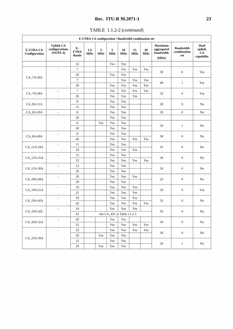
TABLE 1.1.2-2
E-UTRA CA configurations and bandwidth combination sets defined for inter-band CA
(two bands)
E-UTRA CA configuration / Bandwidth combination set
E-UTRA CA
Configuration
Uplink CA
configurations
(NOTE 4)
E-
UTRA
Bands
1.4
MHz
3
MHz
5
MHz
10
MHz
15
MHz
20
MHz
Maximum
aggregated
bandwidth
(MHz)
Bandwidth
combination
set
Dual
uplink
CA
capability
CA_1A-3A - 1 Yes Yes Yes Yes
40 0 Yes 3 Yes Yes Yes Yes
CA_1A-5A
- 1 Yes 20 0 Yes
5 Yes
1 Yes Yes Yes Yes 30 1 Yes
5 Yes Yes
CA_1A-7A - 1 Yes Yes Yes Yes
40 0 Yes 7 Yes Yes Yes
CA_1A-8A
- 1 Yes Yes Yes Yes 30 0 Yes
8 Yes Yes
1 Yes Yes 20 1 Yes
8 Yes Yes
1 Yes Yes Yes Yes 30 2 No
8 Yes Yes Yes
CA_1A-11A - 1 Yes Yes Yes Yes
30 0 No 11 Yes Yes
CA_1A-18A
- 1 Yes Yes Yes Yes 35 0 No
18 Yes Yes Yes
1 Yes Yes 20 1 No
18 Yes Yes
CA_1A-19A - 1 Yes Yes Yes Yes
35 0 Yes 19 Yes Yes Yes
CA_1A-20A - 1 Yes Yes Yes Yes
40 0 No 20 Yes Yes Yes Yes
CA_1A-21A - 1 Yes Yes Yes Yes
35 0 Yes 21 Yes Yes Yes
CA_1A-26A
- 1 Yes Yes Yes Yes 35 0 No
26 Yes Yes Yes
1 Yes Yes 20 1 No
26 Yes Yes
CA_1A-28A
- 1 Yes Yes Yes Yes 40 0
28 Yes Yes Yes Yes
1 Yes Yes 20 1
Rec. ITU-R M.2071-1 19
TABLE 1.1.2-2 (continued)
E-UTRA CA configuration / Bandwidth combination set
E-UTRA CA
Configuration
Uplink CA
configurations
(NOTE 4)
E-
UTRA
Bands
1.4
MHz
3
MHz
5
MHz
10
MHz
15
MHz
20
MHz
Maximum
aggregated
bandwidth
(MHz)
Bandwidth
combination
set
Dual
uplink
CA
capability
28 Yes Yes
CA_1A-41A - 1 Yes Yes Yes Yes
40 0 41 Yes Yes Yes Yes
CA_1A-41C
- 1 Yes Yes Yes Yes
60 0 41
See CA_41C Bandwidth Combination Set 1 in Table 1.1.2-1
CA_1A-42A - 1 Yes Yes Yes Yes
40 0 No 42 Yes Yes Yes Yes
CA_1A-42C - 1 Yes Yes Yes Yes
60 0 No 42 See CA_42C in Table 1.1.2-1
CA_2A-4A
- 2 Yes Yes Yes Yes Yes Yes 40 0 Yes
4 Yes Yes Yes Yes
2 Yes Yes 20 1 Yes
4 Yes Yes
2 Yes Yes Yes Yes 40 2 Yes
4 Yes Yes Yes Yes
CA_2A-4A-4A - 2 Yes Yes Yes Yes
60 0 No 4 See CA_4A-4A in Table 1.1.2-3
CA_2A-5A
- 2 Yes Yes Yes Yes 30 0 No
5 Yes Yes
2 Yes Yes 20 1
5 Yes Yes
CA_2A-2A-5A - 2 See CA_2A-2A in Table 1.1.2-3 50 0
5 Yes Yes
CA_2A-12A
- 2 Yes Yes Yes Yes 30 0 No
12 Yes Yes
2 Yes Yes Yes Yes 30 1 No
12 Yes Yes Yes
CA_2A-12B - 2 Yes Yes Yes Yes
35 0 No 12 See CA_12B in Table 1.1.2-1
CA_2A-13A
- 2 Yes Yes Yes Yes 30 0 Yes
13 Yes
2 Yes Yes 20 1 Yes
13 Yes
CA_2A-2A-
13A
- 2 See CA_2A-2A in Table 1.1.2-3 50 0 No
20 Rec. ITU-R M.2071-1
TABLE 1.1.2-2 (continued)
E-UTRA CA configuration / Bandwidth combination set
E-UTRA CA
Configuration
Uplink CA
configurations
(NOTE 4)
E-
UTRA
Bands
1.4
MHz
3
MHz
5
MHz
10
MHz
15
MHz
20
MHz
Maximum
aggregated
bandwidth
(MHz)
Bandwidth
combination
set
Dual
uplink
CA
capability
13 Yes
CA_2A-17A - 2 Yes Yes
20 0 No 17 Yes Yes
CA_2A-29A
- 2 Yes Yes 20 0 No
29 Yes Yes Yes
2 Yes Yes 20 1 No
29 Yes Yes
2 Yes Yes Yes Yes 30 2 No
29 Yes Yes
CA_2C-29A - 2 See CA_2C in Table 1.1.2-1
50 0 29 Yes Yes
CA_2A-30A - 2 Yes Yes Yes Yes
30 0 No 30 Yes Yes
CA_3A-5A
- 3 Yes Yes Yes 30 0 Yes
5 Yes Yes
3 Yes 20 1 Yes
5 Yes Yes
3 Yes Yes Yes Yes 30 2 Yes
5 Yes Yes
CA_3A-7A - 3 Yes Yes Yes Yes
40 0 Yes 7 Yes Yes Yes
CA_3A-7C
- 3 Yes Yes Yes Yes
60 0 No 7
See CA_7C Bandwidth combination set 1 in table 1.1.2-1
CA_3C-7A - 3 See CA_3C in table 1.1.2-1
60 0 No 7 Yes Yes Yes Yes
CA_3A-8A
- 3 Yes Yes Yes 30 0 Yes
8 Yes Yes
3 Yes 20 1 Yes
8 Yes Yes
3 Yes Yes Yes Yes 30 2 No
8 Yes Yes Yes
CA_3A-19A - 3 Yes Yes Yes Yes
35 0 Yes 19 Yes Yes Yes
CA_3A-20A - 3 Yes Yes Yes Yes 30 0 Yes
Rec. ITU-R M.2071-1 21
TABLE 1.1.2-2 (continued)
E-UTRA CA configuration / Bandwidth combination set
E-UTRA CA
Configuration
Uplink CA
configurations
(NOTE 4)
E-
UTRA
Bands
1.4
MHz
3
MHz
5
MHz
10
MHz
15
MHz
20
MHz
Maximum
aggregated
bandwidth
(MHz)
Bandwidth
combination
set
Dual
uplink
CA
capability
20 Yes Yes
3 Yes Yes Yes Yes 40 1 Yes
20 Yes Yes Yes Yes
CA_3A-26A - 3 Yes Yes Yes Yes 35 0 Yes
26 Yes Yes Yes
3 Yes Yes 20 1 Yes
26 Yes Yes
CA_3A-27A - 3 Yes Yes Yes Yes
30 0 No 27 Yes Yes
CA_3A-28A - 3 Yes Yes Yes Yes
40 0 No 28 Yes Yes Yes Yes
CA_4A-5A
- 4 Yes Yes 20 0 No
5 Yes Yes
4 Yes Yes Yes Yes 30 1 No
5 Yes Yes
CA_4A-4A-5A - 4 See CA_4A-4A in Table 1.1.2-3
50 0 5 Yes Yes
CA_4A-7A - 4 Yes Yes
30 0 Yes 7 Yes Yes Yes Yes
CA_4A-4A-7A
- 4 Yes Yes
40 0 4 Yes Yes
7 Yes Yes Yes Yes
CA_4A-12A
- 4 Yes Yes Yes Yes 20 0 Yes
12 Yes Yes
4 Yes Yes Yes Yes Yes Yes 30 1 Yes
12 Yes Yes
4 Yes Yes Yes Yes 30 2 Yes
12 Yes Yes Yes
4 Yes Yes 20 3 Yes
12 Yes Yes
4 Yes Yes Yes Yes 30 4 Yes
12 Yes Yes
CA_4A-4A-12A
- 4 See CA_4A-4A in Table 1.1.2-3 50 0 No
12 Yes Yes
22 Rec. ITU-R M.2071-1
TABLE 1.1.2-2 (continued)
E-UTRA CA configuration / Bandwidth combination set
E-UTRA CA
Configuration
Uplink CA
configurations
(NOTE 4)
E-
UTRA
Bands
1.4
MHz
3
MHz
5
MHz
10
MHz
15
MHz
20
MHz
Maximum
aggregated
bandwidth
(MHz)
Bandwidth
combination
set
Dual
uplink
CA
capability
CA_4A-12B - 4 Yes Yes Yes Yes
35 0 No 12 See CA_12B in Table 1.1.2-1
CA_4A-13A
- 4 Yes Yes Yes Yes 30 0 Yes
13 Yes
4 Yes Yes 20 1 Yes
13 Yes
CA_4A-4A-13A
- 4 See CA_4A-4A in Table 1.1.2-3 50 0 No
13 Yes
CA_4A-17A - 4 Yes Yes
20 0 Yes 17 Yes Yes
CA_4A-27A - 4 Yes Yes Yes Yes
30 0 No 27 Yes Yes Yes
CA_4A-29A
- 4 Yes Yes 20 0 No
29 Yes Yes Yes
4 Yes Yes 20 1 No
29 Yes Yes
4 Yes Yes Yes Yes 30 2 No
29 Yes Yes
CA_4A-30A - 4 Yes Yes Yes Yes
30 0 No 30 Yes Yes
CA_5A-7A - 5 Yes Yes Yes Yes
30 0 Yes 7 Yes Yes Yes
CA_5A-12A - 5 Yes Yes
20 0 Yes 12 Yes Yes
CA_5A-13A - 5 Yes Yes
20 0 13 Yes
CA_5A-17A - 5 Yes Yes
20 0 Yes 17 Yes Yes
CA_5A-25A - 5 Yes Yes
30 0 No 25 Yes Yes Yes Yes
CA_5A-30A - 5 Yes Yes
20 0 No 30 Yes Yes
CA_7A-8A - 7 Yes Yes Yes
30 0 8 Yes Yes Yes
CA_7A-12A - 7 Yes Yes Yes Yes 30 0
Rec. ITU-R M.2071-1 23
TABLE 1.1.2-2 (continued)
E-UTRA CA configuration / Bandwidth combination set
E-UTRA CA
Configuration
Uplink CA
configurations
(NOTE 4)
E-
UTRA
Bands
1.4
MHz
3
MHz
5
MHz
10
MHz
15
MHz
20
MHz
Maximum
aggregated
bandwidth
(MHz)
Bandwidth
combination
set
Dual
uplink
CA
capability
12 Yes Yes
CA_7A-20A
- 7 Yes Yes Yes 30 0 Yes
20 Yes Yes
7 Yes Yes Yes 40 1 Yes
20 Yes Yes Yes Yes
CA_7A-28A - 7 Yes Yes Yes Yes
35 0 Yes 28 Yes Yes Yes
CA_8A-11A - 8 Yes Yes
20 0 No 11 Yes Yes
CA_8A-20A - 8 Yes Yes 20 0 No
20 Yes Yes
8 Yes Yes Yes 20 1 No
20 Yes Yes
CA_8A-40A - 8 Yes Yes
30 0 No 40 Yes Yes Yes Yes
CA_11A-18A - 11 Yes Yes
25 0 No 18 Yes Yes Yes
CA_12A-25A - 12 Yes Yes
30 0 No 25 Yes Yes Yes Yes
CA_12A-30A - 12 Yes Yes
20 0 No 30 Yes Yes
CA_18A-28A - 18 Yes Yes Yes
25 0 No 28 Yes Yes
CA_19A-21A - 19 Yes Yes Yes
30 0 Yes 21 Yes Yes Yes
CA_19A-42A - 19 Yes Yes Yes
35 0 No 42 Yes Yes Yes Yes
CA_19A-42C - 19 Yes Yes Yes
55 0 No 42 See CA_42C in Table 1.1.2-1
CA_20A-32A - 20 Yes Yes
30 0 No 32 Yes Yes Yes Yes
CA_23A-29A
- 23 Yes Yes Yes Yes 30 0 No
29 Yes Yes Yes
23 Yes Yes 20 1 No
29 Yes Yes Yes
24 Rec. ITU-R M.2071-1
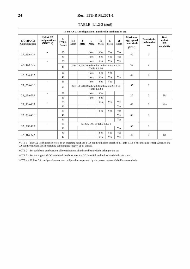
TABLE 1.1.2-2 (end)
E-UTRA CA configuration / Bandwidth combination set
E-UTRA CA
Configuration
Uplink CA
configurations
(NOTE 4)
E-
UTRA
Bands
1.4
MHz
3
MHz
5
MHz
10
MHz
15
MHz
20
MHz
Maximum
aggregated
bandwidth
(MHz)
Bandwidth
combination
set
Dual
uplink
CA
capability
CA_25A-41A - 25 Yes Yes Yes Yes
40 0 41 Yes Yes Yes Yes
CA_25A-41C
- 25 Yes Yes Yes Yes
60 0 41
See CA_41C Bandwidth Combination Set 1 in Table 1.1.2-1
CA_26A-41A - 26 Yes Yes Yes
40 0 41 Yes Yes Yes Yes
CA_26A-41C
- 26 Yes Yes Yes
55 0 41
See CA_41C Bandwidth Combination Set 1 in Table 1.1.2-1
CA_29A-30A - 29 Yes Yes
20 0 No 30 Yes Yes
CA_39A-41A - 39 Yes Yes Yes
40 0 Yes 41 Yes
CA_39A-41C
- 39 Yes Yes Yes
60 0 41 Yes
41 Yes
CA_39C-41A - 39 See CA_39C in Table 1.1.2-1
55 0 41 Yes
CA_41A-42A - 41 Yes Yes Yes
40 0 No 42 Yes Yes Yes
NOTE 1 – The CA Configuration refers to an operating band and a CA bandwidth class specified in Table 1.1.2-4 (the indexing letter). Absence of a CA bandwidth class for an operating band implies support of all classes.
NOTE 2 – For each band combination, all combinations of indicated bandwidths belong to the set.
NOTE 3 – For the supported CC bandwidth combinations, the CC downlink and uplink bandwidths are equal.
NOTE 4 – Uplink CA configurations are the configurations supported by the present release of the Recommendation.
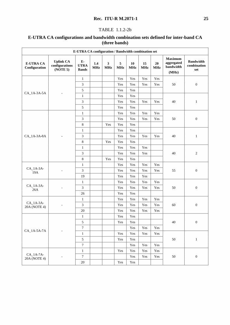
Rec. ITU-R M.2071-1 25
TABLE 1.1.2-2b
E-UTRA CA configurations and bandwidth combination sets defined for inter-band CA
(three bands)
E-UTRA CA configuration / Bandwidth combination set
E-UTRA CA
Configuration
Uplink CA
configurations
(NOTE 5)
E-
UTRA
Bands
1.4
MHz
3
MHz
5
MHz
10
MHz
15
MHz
20
MHz
Maximum
aggregated
bandwidth
(MHz)
Bandwidth
combination
set
CA_1A-3A-5A -
1 Yes Yes Yes Yes
50 0 3 Yes Yes Yes Yes
5 Yes Yes
1 Yes Yes
40 1 3 Yes Yes Yes Yes
5 Yes Yes
CA_1A-3A-8A -
1 Yes Yes Yes Yes
50 0 3 Yes Yes Yes Yes
8 Yes Yes Yes
1 Yes Yes
40 1 3 Yes Yes Yes Yes
8 Yes Yes Yes
1 Yes Yes Yes
40 2 3 Yes Yes Yes
8 Yes Yes Yes
CA_1A-3A-
19A -
1 Yes Yes Yes Yes
55 0 3 Yes Yes Yes Yes
19 Yes Yes Yes
CA_1A-3A-
26A -
1 Yes Yes Yes Yes
50 0 3 Yes Yes Yes Yes
26 Yes Yes
CA_1A-3A-
20A (NOTE 4) -
1 Yes Yes Yes Yes
60 0 3 Yes Yes Yes Yes
20 Yes Yes Yes Yes
CA_1A-5A-7A -
1 Yes Yes
40 0 5 Yes Yes
7 Yes Yes Yes
1 Yes Yes Yes Yes
50 1 5 Yes Yes
7 Yes Yes Yes
CA_1A-7A-
20A (NOTE 4) -
1 Yes Yes Yes Yes
50 0 7 Yes Yes Yes
20 Yes Yes
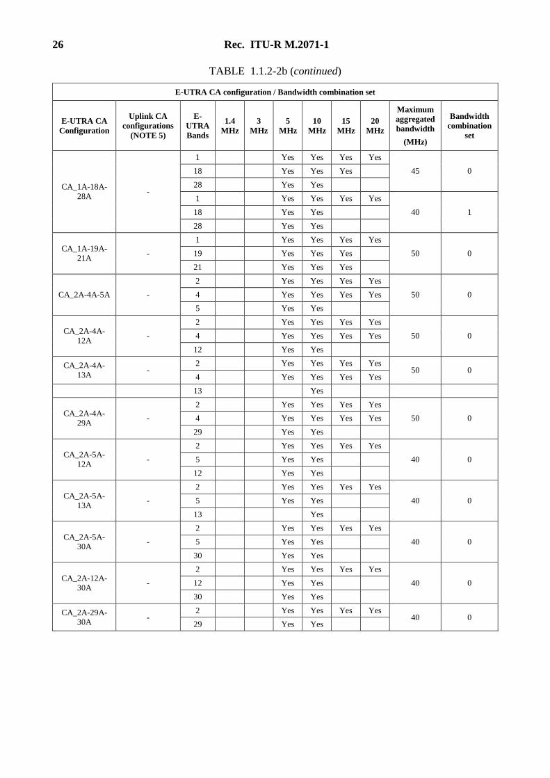
26 Rec. ITU-R M.2071-1
TABLE 1.1.2-2b (continued)
E-UTRA CA configuration / Bandwidth combination set
E-UTRA CA
Configuration
Uplink CA
configurations
(NOTE 5)
E-
UTRA
Bands
1.4
MHz
3
MHz
5
MHz
10
MHz
15
MHz
20
MHz
Maximum
aggregated
bandwidth
(MHz)
Bandwidth
combination
set
CA_1A-18A-
28A -
1 Yes Yes Yes Yes
45 0 18 Yes Yes Yes
28 Yes Yes
1 Yes Yes Yes Yes
40 1 18 Yes Yes
28 Yes Yes
CA_1A-19A-
21A -
1 Yes Yes Yes Yes
50 0 19 Yes Yes Yes
21 Yes Yes Yes
CA_2A-4A-5A -
2 Yes Yes Yes Yes
50 0 4 Yes Yes Yes Yes
5 Yes Yes
CA_2A-4A-
12A -
2 Yes Yes Yes Yes
50 0 4 Yes Yes Yes Yes
12 Yes Yes
CA_2A-4A-
13A -
2 Yes Yes Yes Yes 50 0
4 Yes Yes Yes Yes
13 Yes
CA_2A-4A-
29A -
2 Yes Yes Yes Yes
50 0 4 Yes Yes Yes Yes
29 Yes Yes
CA_2A-5A-
12A -
2 Yes Yes Yes Yes
40 0 5 Yes Yes
12 Yes Yes
CA_2A-5A-
13A -
2 Yes Yes Yes Yes
40 0 5 Yes Yes
13 Yes
CA_2A-5A-
30A -
2 Yes Yes Yes Yes
40 0 5 Yes Yes
30 Yes Yes
CA_2A-12A-
30A -
2 Yes Yes Yes Yes
40 0 12 Yes Yes
30 Yes Yes
CA_2A-29A-
30A -
2 Yes Yes Yes Yes 40 0
29 Yes Yes
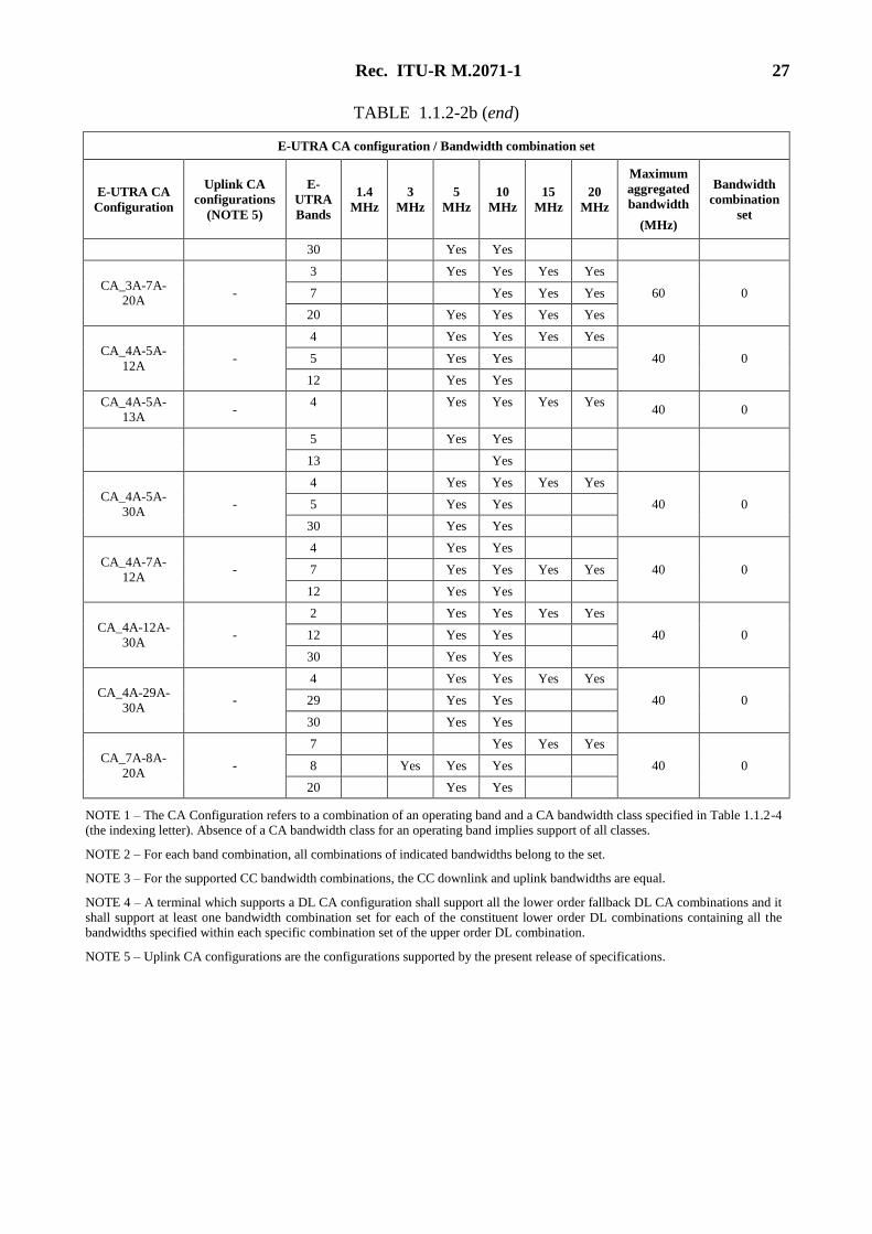
Rec. ITU-R M.2071-1 27
TABLE 1.1.2-2b (end)
E-UTRA CA configuration / Bandwidth combination set
E-UTRA CA
Configuration
Uplink CA
configurations
(NOTE 5)
E-
UTRA
Bands
1.4
MHz
3
MHz
5
MHz
10
MHz
15
MHz
20
MHz
Maximum
aggregated
bandwidth
(MHz)
Bandwidth
combination
set
30 Yes Yes
CA_3A-7A-20A
-
3 Yes Yes Yes Yes
60 0 7 Yes Yes Yes
20 Yes Yes Yes Yes
CA_4A-5A-
12A -
4 Yes Yes Yes Yes
40 0 5 Yes Yes
12 Yes Yes
CA_4A-5A-
13A -
4 Yes Yes Yes Yes 40 0
5 Yes Yes
13 Yes
CA_4A-5A-
30A -
4 Yes Yes Yes Yes
40 0 5 Yes Yes
30 Yes Yes
CA_4A-7A-
12A -
4 Yes Yes
40 0 7 Yes Yes Yes Yes
12 Yes Yes
CA_4A-12A-
30A -
2 Yes Yes Yes Yes
40 0 12 Yes Yes
30 Yes Yes
CA_4A-29A-
30A -
4 Yes Yes Yes Yes
40 0 29 Yes Yes
30 Yes Yes
CA_7A-8A-
20A -
7 Yes Yes Yes
40 0 8 Yes Yes Yes
20 Yes Yes
NOTE 1 – The CA Configuration refers to a combination of an operating band and a CA bandwidth class specified in Table 1.1.2-4 (the indexing letter). Absence of a CA bandwidth class for an operating band implies support of all classes.
NOTE 2 – For each band combination, all combinations of indicated bandwidths belong to the set.
NOTE 3 – For the supported CC bandwidth combinations, the CC downlink and uplink bandwidths are equal.
NOTE 4 – A terminal which supports a DL CA configuration shall support all the lower order fallback DL CA combinations and it
shall support at least one bandwidth combination set for each of the constituent lower order DL combinations containing all the bandwidths specified within each specific combination set of the upper order DL combination.
NOTE 5 – Uplink CA configurations are the configurations supported by the present release of specifications.
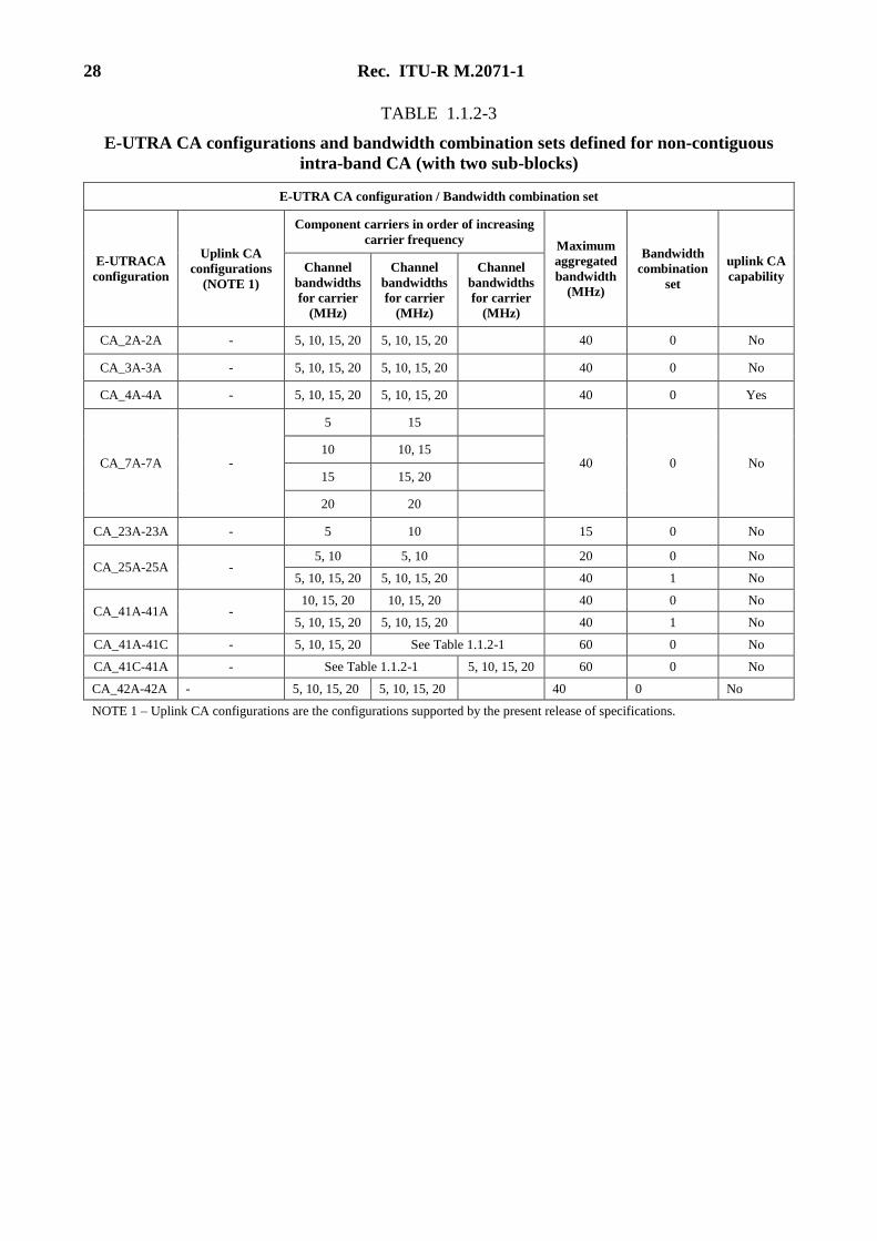
28 Rec. ITU-R M.2071-1
TABLE 1.1.2-3
E-UTRA CA configurations and bandwidth combination sets defined for non-contiguous
intra-band CA (with two sub-blocks)
E-UTRA CA configuration / Bandwidth combination set
E-UTRACA
configuration
Uplink CA
configurations
(NOTE 1)
Component carriers in order of increasing
carrier frequency Maximum
aggregated
bandwidth
(MHz)
Bandwidth
combination
set
uplink CA
capability Channel
bandwidths
for carrier
(MHz)
Channel
bandwidths
for carrier
(MHz)
Channel
bandwidths
for carrier
(MHz)
CA_2A-2A - 5, 10, 15, 20 5, 10, 15, 20 40 0 No
CA_3A-3A - 5, 10, 15, 20 5, 10, 15, 20 40 0 No
CA_4A-4A - 5, 10, 15, 20 5, 10, 15, 20 40 0 Yes
CA_7A-7A -
5 15
40 0 No 10 10, 15
15 15, 20
20 20
CA_23A-23A - 5 10 15 0 No
CA_25A-25A - 5, 10 5, 10 20 0 No
5, 10, 15, 20 5, 10, 15, 20 40 1 No
CA_41A-41A - 10, 15, 20 10, 15, 20 40 0 No
5, 10, 15, 20 5, 10, 15, 20 40 1 No
CA_41A-41C - 5, 10, 15, 20 See Table 1.1.2-1 60 0 No
CA_41C-41A - See Table 1.1.2-1 5, 10, 15, 20 60 0 No
CA_42A-42A - 5, 10, 15, 20 5, 10, 15, 20 40 0 No
NOTE 1 – Uplink CA configurations are the configurations supported by the present release of specifications.
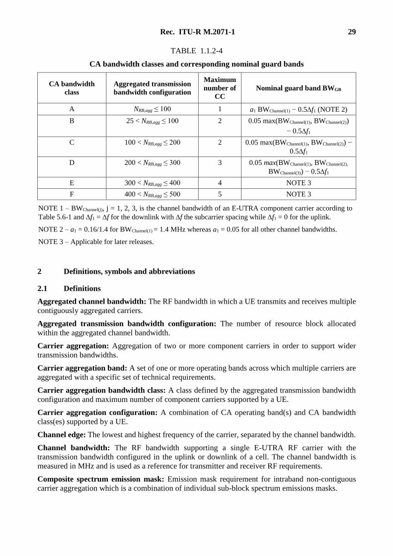
Rec. ITU-R M.2071-1 29
TABLE 1.1.2-4
CA bandwidth classes and corresponding nominal guard bands
CA bandwidth
class
Aggregated transmission
bandwidth configuration
Maximum
number of
CC
Nominal guard band BWGB
A NRB,agg ≤ 100 1 a1 BWChannel(1) − 0.5f1 (NOTE 2)
B 25 < NRB,agg ≤ 100 2 0.05 max(BWChannel(1), BWChannel(2))
− 0.5f1
C 100 < NRB,agg ≤ 200 2 0.05 max(BWChannel(1), BWChannel(2)) −
0.5f1
D 200 < NRB,agg ≤ 300 3 0.05 max(BWChannel(1), BWChannel(2),
BWChannel(3)) − 0.5f1
E 300 < NRB,agg ≤ 400 4 NOTE 3
F 400 < NRB,agg ≤ 500 5 NOTE 3
NOTE 1 – BWChannel(j), j = 1, 2, 3, is the channel bandwidth of an E-UTRA component carrier according to
Table 5.6-1 and f1 = f for the downlink with f the subcarrier spacing while f1 = 0 for the uplink.
NOTE 2 – a1 = 0.16/1.4 for BWChannel(1) = 1.4 MHz whereas a1 = 0.05 for all other channel bandwidths.
NOTE 3 – Applicable for later releases.
2 Definitions, symbols and abbreviations
2.1 Definitions
Aggregated channel bandwidth: The RF bandwidth in which a UE transmits and receives multiple
contiguously aggregated carriers.
Aggregated transmission bandwidth configuration: The number of resource block allocated
within the aggregated channel bandwidth.
Carrier aggregation: Aggregation of two or more component carriers in order to support wider
transmission bandwidths.
Carrier aggregation band: A set of one or more operating bands across which multiple carriers are
aggregated with a specific set of technical requirements.
Carrier aggregation bandwidth class: A class defined by the aggregated transmission bandwidth
configuration and maximum number of component carriers supported by a UE.
Carrier aggregation configuration: A combination of CA operating band(s) and CA bandwidth
class(es) supported by a UE.
Channel edge: The lowest and highest frequency of the carrier, separated by the channel bandwidth.
Channel bandwidth: The RF bandwidth supporting a single E-UTRA RF carrier with the
transmission bandwidth configured in the uplink or downlink of a cell. The channel bandwidth is
measured in MHz and is used as a reference for transmitter and receiver RF requirements.
Composite spectrum emission mask: Emission mask requirement for intraband non-contiguous
carrier aggregation which is a combination of individual sub-block spectrum emissions masks.
30 Rec. ITU-R M.2071-1
Composite spurious emission requirement: Spurious emission requirement for intraband non-
contiguous carrier aggregation which is a combination of individual sub-block spurious emission
requirements.
Contiguous carriers: A set of two or more carriers configured in a spectrum block where there are
no RF requirements based on co-existence for un-coordinated operation within the spectrum block.
Contiguous resource allocation: A resource allocation of consecutive resource blocks within one
carrier or across contiguously aggregated carriers. The gap between contiguously aggregated carriers
due to the nominal channel spacing is allowed.
Contiguous spectrum: Spectrum consisting of a contiguous block of spectrum with no sub-block
gaps.
Enhanced performance requirements type A: This defines performance requirements assuming as
baseline receiver reference symbol based linear minimum mean square error interference rejection
combining.
Inter-band carrier aggregation: Carrier aggregation of component carriers in different operating
bands.
NOTE – Carriers aggregated in each band can be contiguous or non-contiguous.
Intra-band contiguous carrier aggregation: Contiguous carriers aggregated in the same operating
band.
Intra-band non-contiguous carrier aggregation: Non-contiguous carriers aggregated in the same
operating band.
Lower sub-block edge: The frequency at the lower edge of one sub-block. It is used as a frequency
reference point for both transmitter and receiver requirements.
Non-contiguous spectrum: Spectrum consisting of two or more sub-blocks separated by sub-block
gap(s).
Sub-block: This is one contiguous allocated block of spectrum for transmission and reception by the
same UE. There may be multiple instances of sub-blocks within an RF bandwidth.
Sub-block bandwidth: The bandwidth of one sub-block.
Sub-block gap: A frequency gap between two consecutive sub-blocks within an RF bandwidth,
where the RF requirements in the gap are based on co-existence for un-coordinated operation.
Synchronized operation: Operation of TDD in two different systems, where no simultaneous uplink
and downlink occur.
Unsynchronized operation: Operation of TDD in two different systems, where the conditions for
synchronized operation.
Upper sub-block edge: The frequency at the upper edge of one sub-block. It is used as a frequency
reference point for both transmitter and receiver requirements.
2.2 Symbols
For the purposes of the present Recommendation, the following symbols apply:
BWChannel Channel bandwidth
BWChannel_CA Aggregated channel bandwidth, expressed in MHz
BWGB Virtual guard band to facilitate transmitter (receiver) filtering above/below
edge CCs
Rec. ITU-R M.2071-1 31
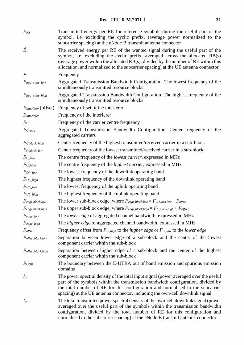
ERS Transmitted energy per RE for reference symbols during the useful part of the
symbol, i.e. excluding the cyclic prefix, (average power normalized to the
subcarrier spacing) at the eNode B transmit antenna connector
Ês The received energy per RE of the wanted signal during the useful part of the
symbol, i.e. excluding the cyclic prefix, averaged across the allocated RB(s)
(average power within the allocated RB(s), divided by the number of RE within this
allocation, and normalized to the subcarrier spacing) at the UE antenna connector
F Frequency
Fagg_alloc_low Aggregated Transmission Bandwidth Configuration. The lowest frequency of the
simultaneously transmitted resource blocks
Fagg_alloc_high Aggregated Transmission Bandwidth Configuration. The highest frequency of the
simultaneously transmitted resource blocks
FInterferer (offset) Frequency offset of the interferer
FInterferer Frequency of the interferer
FC Frequency of the carrier centre frequency
FC_agg Aggregated Transmission Bandwidth Configuration. Center frequency of the
aggregated carriers
FC,block, high Center frequency of the highest transmitted/received carrier in a sub-block
FC,block, low Center frequency of the lowest transmitted/received carrier in a sub-block
FC_low The centre frequency of the lowest carrier, expressed in MHz
FC_high The centre frequency of the highest carrier, expressed in MHz
FDL_low The lowest frequency of the downlink operating band
FDL_high The highest frequency of the downlink operating band
FUL_low The lowest frequency of the uplink operating band
FUL_high The highest frequency of the uplink operating band
Fedge,block,low The lower sub-block edge, where Fedge,block,low = FC,block,low − Foffset.
Fedge,block,high The upper sub-block edge, where Fedge,block,high = FC,block,high + Foffset.
Fedge_low The lower edge of aggregated channel bandwidth, expressed in MHz
Fedge_high The higher edge of aggregated channel bandwidth, expressed in MHz
Foffset Frequency offset from FC_high to the higher edge or FC_low to the lower edge
Foffset,block,low Separation between lower edge of a sub-block and the center of the lowest
component carrier within the sub-block
Foffset,block,high Separation between higher edge of a sub-block and the center of the highest
component carrier within the sub-block
FOOB The boundary between the E-UTRA out of band emission and spurious emission
domains
Io The power spectral density of the total input signal (power averaged over the useful
part of the symbols within the transmission bandwidth configuration, divided by
the total number of RE for this configuration and normalised to the subcarrier
spacing) at the UE antenna connector, including the own-cell downlink signal
Ior The total transmitted power spectral density of the own-cell downlink signal (power
averaged over the useful part of the symbols within the transmission bandwidth
configuration, divided by the total number of RE for this configuration and
normalised to the subcarrier spacing) at the eNode B transmit antenna connector
32 Rec. ITU-R M.2071-1
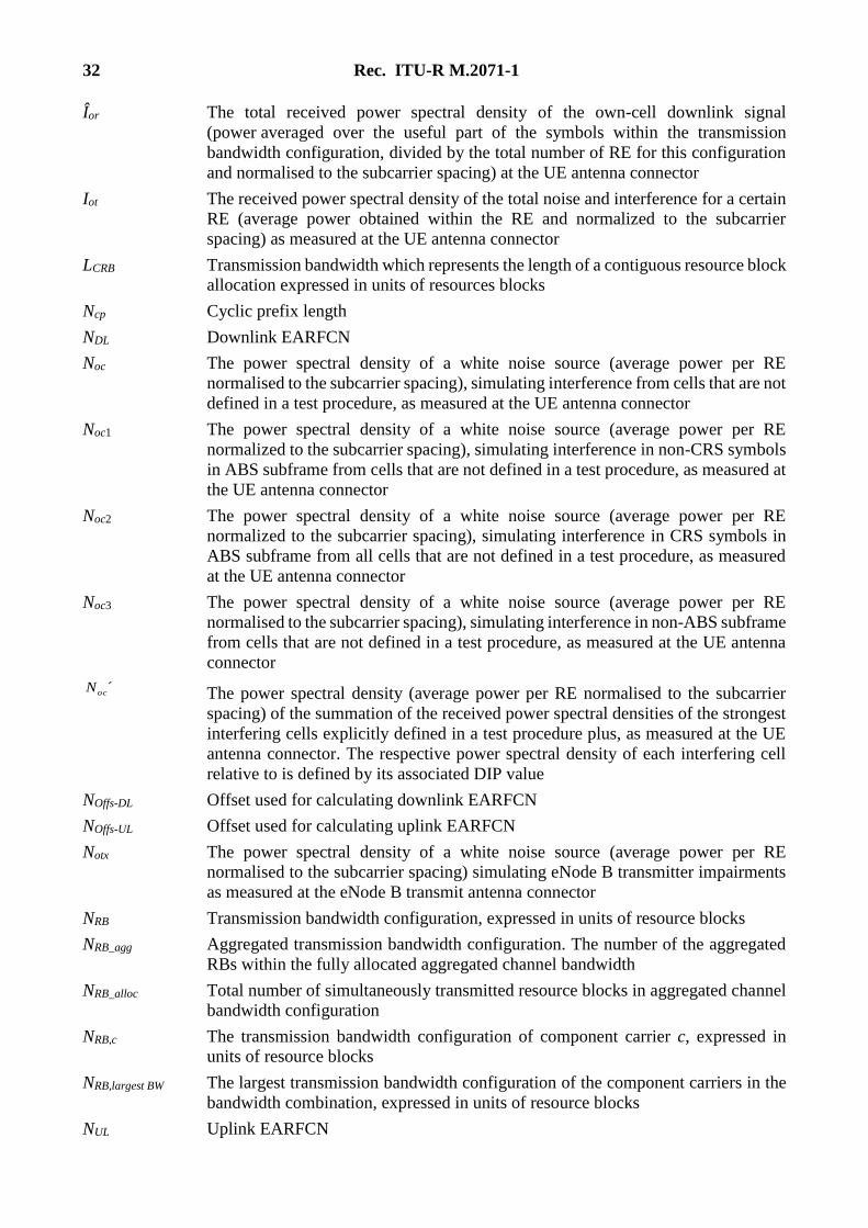
Îor The total received power spectral density of the own-cell downlink signal
(power averaged over the useful part of the symbols within the transmission
bandwidth configuration, divided by the total number of RE for this configuration
and normalised to the subcarrier spacing) at the UE antenna connector
Iot The received power spectral density of the total noise and interference for a certain
RE (average power obtained within the RE and normalized to the subcarrier
spacing) as measured at the UE antenna connector
LCRB Transmission bandwidth which represents the length of a contiguous resource block
allocation expressed in units of resources blocks
Ncp Cyclic prefix length
NDL Downlink EARFCN
Noc The power spectral density of a white noise source (average power per RE
normalised to the subcarrier spacing), simulating interference from cells that are not
defined in a test procedure, as measured at the UE antenna connector
Noc1 The power spectral density of a white noise source (average power per RE
normalized to the subcarrier spacing), simulating interference in non-CRS symbols
in ABS subframe from cells that are not defined in a test procedure, as measured at
the UE antenna connector
Noc2 The power spectral density of a white noise source (average power per RE
normalized to the subcarrier spacing), simulating interference in CRS symbols in
ABS subframe from all cells that are not defined in a test procedure, as measured
at the UE antenna connector
Noc3 The power spectral density of a white noise source (average power per RE
normalised to the subcarrier spacing), simulating interference in non-ABS subframe
from cells that are not defined in a test procedure, as measured at the UE antenna
connector
´ocN The power spectral density (average power per RE normalised to the subcarrier
spacing) of the summation of the received power spectral densities of the strongest
interfering cells explicitly defined in a test procedure plus, as measured at the UE
antenna connector. The respective power spectral density of each interfering cell
relative to is defined by its associated DIP value
NOffs-DL Offset used for calculating downlink EARFCN
NOffs-UL Offset used for calculating uplink EARFCN
Notx The power spectral density of a white noise source (average power per RE
normalised to the subcarrier spacing) simulating eNode B transmitter impairments
as measured at the eNode B transmit antenna connector
NRB Transmission bandwidth configuration, expressed in units of resource blocks
NRB_agg Aggregated transmission bandwidth configuration. The number of the aggregated
RBs within the fully allocated aggregated channel bandwidth
NRB_alloc Total number of simultaneously transmitted resource blocks in aggregated channel
bandwidth configuration
NRB,c The transmission bandwidth configuration of component carrier c, expressed in
units of resource blocks
NRB,largest BW The largest transmission bandwidth configuration of the component carriers in the
bandwidth combination, expressed in units of resource blocks
NUL Uplink EARFCN
Rec. ITU-R M.2071-1 33
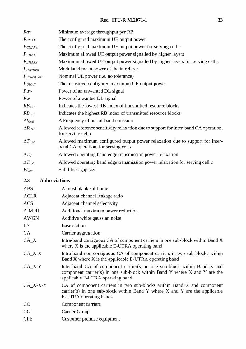
Rav Minimum average throughput per RB
PCMAX The configured maximum UE output power
PCMAX,c The configured maximum UE output power for serving cell c
PEMAX Maximum allowed UE output power signalled by higher layers
PEMAX,c Maximum allowed UE output power signalled by higher layers for serving cell c
PInterferer Modulated mean power of the interferer
PPowerClass Nominal UE power (i.e. no tolerance)
PUMAX The measured configured maximum UE output power
Puw Power of an unwanted DL signal
Pw Power of a wanted DL signal
RBstart Indicates the lowest RB index of transmitted resource blocks
RBend Indicates the highest RB index of transmitted resource blocks
ΔfOoB Δ Frequency of out-of-band emission
ΔRIB,c Allowed reference sensitivity relaxation due to support for inter-band CA operation,
for serving cell c
ΔTIB,c Allowed maximum configured output power relaxation due to support for inter-
band CA operation, for serving cell c
TC Allowed operating band edge transmission power relaxation
TC,c Allowed operating band edge transmission power relaxation for serving cell c
Wgap Sub-block gap size
2.3 Abbreviations
ABS Almost blank subframe
ACLR Adjacent channel leakage ratio
ACS Adjacent channel selectivity
A-MPR Additional maximum power reduction
AWGN Additive white gaussian noise
BS Base station
CA Carrier aggregation
CA_X Intra-band contiguous CA of component carriers in one sub-block within Band X
where X is the applicable E-UTRA operating band
CA_X-X Intra-band non-contiguous CA of component carriers in two sub-blocks within
Band X where X is the applicable E-UTRA operating band
CA_X-Y Inter-band CA of component carrier(s) in one sub-block within Band X and
component carrier(s) in one sub-block within Band Y where X and Y are the
applicable E-UTRA operating band
CA_X-X-Y CA of component carriers in two sub-blocks within Band X and component
carrier(s) in one sub-block within Band Y where X and Y are the applicable
E-UTRA operating bands
CC Component carriers
CG Carrier Group
CPE Customer premise equipment
34 Rec. ITU-R M.2071-1
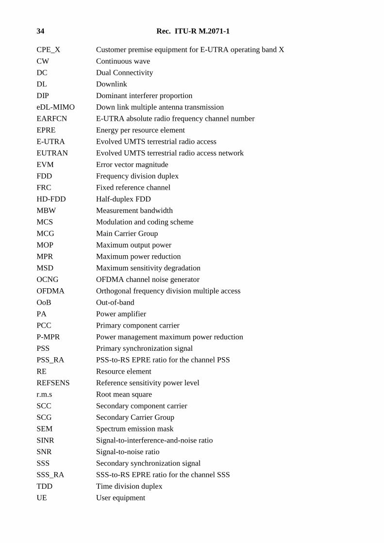
CPE_X Customer premise equipment for E-UTRA operating band X
CW Continuous wave
DC Dual Connectivity
DL Downlink
DIP Dominant interferer proportion
eDL-MIMO Down link multiple antenna transmission
EARFCN E-UTRA absolute radio frequency channel number
EPRE Energy per resource element
E-UTRA Evolved UMTS terrestrial radio access
EUTRAN Evolved UMTS terrestrial radio access network
EVM Error vector magnitude
FDD Frequency division duplex
FRC Fixed reference channel
HD-FDD Half-duplex FDD
MBW Measurement bandwidth
MCS Modulation and coding scheme
MCG Main Carrier Group
MOP Maximum output power
MPR Maximum power reduction
MSD Maximum sensitivity degradation
OCNG OFDMA channel noise generator
OFDMA Orthogonal frequency division multiple access
OoB Out-of-band
PA Power amplifier
PCC Primary component carrier
P-MPR Power management maximum power reduction
PSS Primary synchronization signal
PSS_RA PSS-to-RS EPRE ratio for the channel PSS
RE Resource element
REFSENS Reference sensitivity power level
r.m.s Root mean square
SCC Secondary component carrier
SCG Secondary Carrier Group
SEM Spectrum emission mask
SINR Signal-to-interference-and-noise ratio
SNR Signal-to-noise ratio
SSS Secondary synchronization signal
SSS_RA SSS-to-RS EPRE ratio for the channel SSS
TDD Time division duplex
UE User equipment
Rec. ITU-R M.2071-1 35
UL Uplink
UL-MIMO Up link multiple antenna transmission
UMTS Universal mobile telecommunications system
UTRA UMTS terrestrial radio access
UTRAN UMTS terrestrial radio access network
xCH_RA xCH-to-RS EPRE ratio for the channel xCH in all transmitted OFDM symbols not
containing RS
xCH_RB xCH-to-RS EPRE ratio for the channel xCH in all transmitted OFDM symbols
containing RS
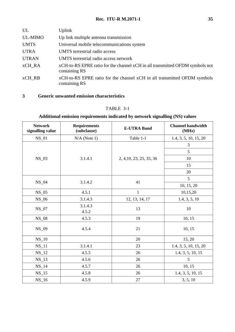
3 Generic unwanted emission characteristics
TABLE 3-1
Additional emission requirements indicated by network signalling (NS) values
Network
signalling value
Requirements
(subclause) E-UTRA Band
Channel bandwidth
(MHz)
NS_01 N/A (Note 1) Table 1-1 1.4, 3, 5, 10, 15, 20
NS_03 3.1.4.1 2, 4,10, 23, 25, 35, 36
3
5
10
15
20
NS_04 3.1.4.2 41 5
10, 15, 20
NS_05 4.5.1 1 10,15,20
NS_06 3.1.4.3 12, 13, 14, 17 1.4, 3, 5, 10
NS_07 3.1.4.3
4.5.2 13 10
NS_08 4.5.3 19 10, 15
NS_09 4.5.4 21 10, 15
NS_10 20 15, 20
NS_11 3.1.4.1 23 1.4, 3, 5, 10, 15, 20
NS_12 4.5.5 26 1.4, 3, 5, 10, 15
NS_13 4.5.6 26 5
NS_14 4.5.7 26 10, 15
NS_15 4.5.8 26 1.4, 3, 5, 10, 15
NS_16 4.5.9 27 3, 5, 10
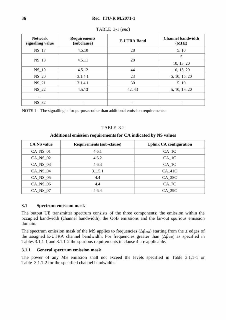
36 Rec. ITU-R M.2071-1
TABLE 3-1 (end)
Network
signalling value
Requirements
(subclause) E-UTRA Band
Channel bandwidth
(MHz)
NS_17 4.5.10 28 5, 10
NS_18 4.5.11 28 5
10, 15, 20
NS_19 4.5.12 44 10, 15, 20
NS_20 3.1.4.1 23 5, 10, 15, 20
NS_21 3.1.4.1 30 5, 10
NS_22 4.5.13 42, 43 5, 10, 15, 20
...
NS_32 - - -
NOTE 1 – The signalling is for purposes other than additional emission requirements.
TABLE 3-2
Additional emission requirements for CA indicated by NS values
CA NS value Requirements (sub-clause) Uplink CA configuration
CA_NS_01 4.6.1 CA_1C
CA_NS_02 4.6.2 CA_1C
CA_NS_03 4.6.3 CA_1C
CA_NS_04 3.1.5.1 CA_41C
CA_NS_05 4.4 CA_38C
CA_NS_06 4.4 CA_7C
CA_NS_07 4.6.4 CA_39C
3.1 Spectrum emission mask
The output UE transmitter spectrum consists of the three components; the emission within the
occupied bandwidth (channel bandwidth), the OoB emissions and the far-out spurious emission
domain.
The spectrum emission mask of the MS applies to frequencies (ΔfOoB) starting from the ± edges of
the assigned E-UTRA channel bandwidth. For frequencies greater than (ΔfOoB) as specified in
Tables 3.1.1-1 and 3.1.1-2 the spurious requirements in clause 4 are applicable.
3.1.1 General spectrum emission mask
The power of any MS emission shall not exceed the levels specified in Table 3.1.1-1 or
Table 3.1.1-2 for the specified channel bandwidths.
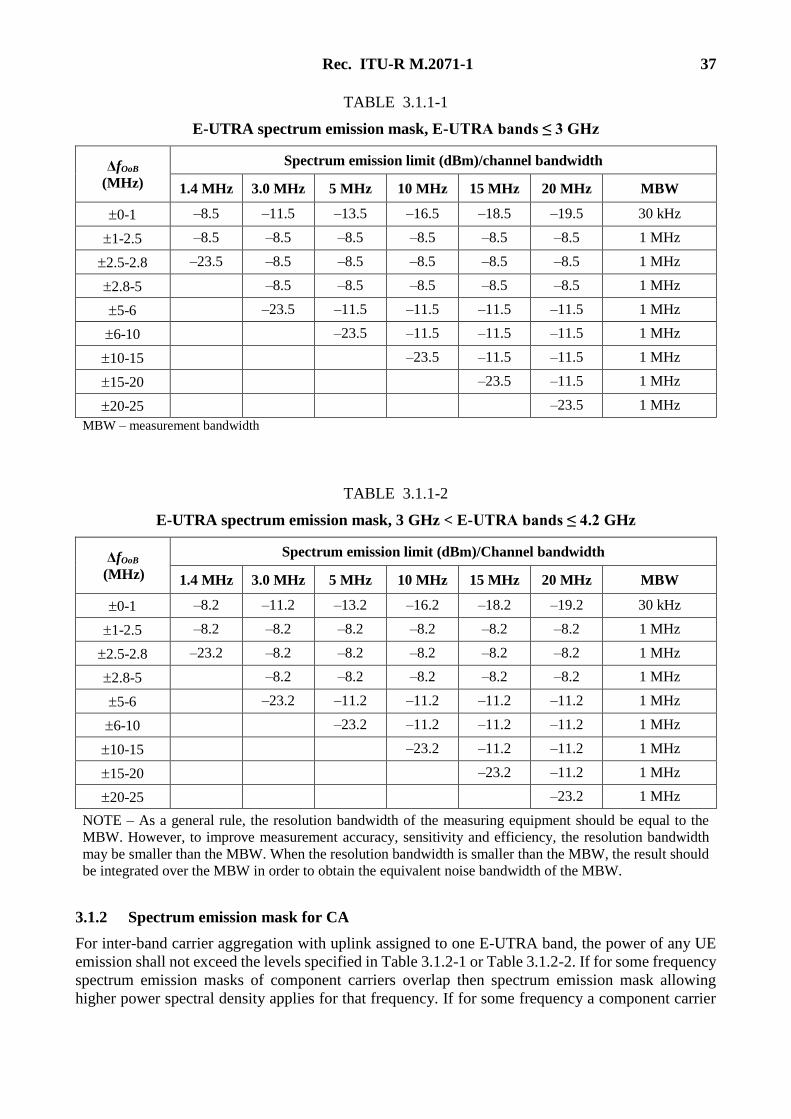
Rec. ITU-R M.2071-1 37
TABLE 3.1.1-1
E-UTRA spectrum emission mask, E-UTRA bands ≤ 3 GHz
ΔfOoB
(MHz)
Spectrum emission limit (dBm)/channel bandwidth
1.4 MHz 3.0 MHz 5 MHz 10 MHz 15 MHz 20 MHz MBW
0-1 –8.5 –11.5 –13.5 –16.5 –18.5 –19.5 30 kHz
1-2.5 –8.5 –8.5 –8.5 –8.5 –8.5 –8.5 1 MHz
2.5-2.8 –23.5 –8.5 –8.5 –8.5 –8.5 –8.5 1 MHz
2.8-5 –8.5 –8.5 –8.5 –8.5 –8.5 1 MHz
5-6 –23.5 –11.5 –11.5 –11.5 –11.5 1 MHz
6-10 –23.5 –11.5 –11.5 –11.5 1 MHz
10-15 –23.5 –11.5 –11.5 1 MHz
15-20 –23.5 –11.5 1 MHz
20-25 –23.5 1 MHz
MBW – measurement bandwidth
TABLE 3.1.1-2
E-UTRA spectrum emission mask, 3 GHz < E-UTRA bands ≤ 4.2 GHz
ΔfOoB
(MHz)
Spectrum emission limit (dBm)/Channel bandwidth
1.4 MHz 3.0 MHz 5 MHz 10 MHz 15 MHz 20 MHz MBW
0-1 –8.2 –11.2 –13.2 –16.2 –18.2 –19.2 30 kHz
1-2.5 –8.2 –8.2 –8.2 –8.2 –8.2 –8.2 1 MHz
2.5-2.8 –23.2 –8.2 –8.2 –8.2 –8.2 –8.2 1 MHz
2.8-5 –8.2 –8.2 –8.2 –8.2 –8.2 1 MHz
5-6 –23.2 –11.2 –11.2 –11.2 –11.2 1 MHz
6-10 –23.2 –11.2 –11.2 –11.2 1 MHz
10-15 –23.2 –11.2 –11.2 1 MHz
15-20 –23.2 –11.2 1 MHz
20-25 –23.2 1 MHz
NOTE – As a general rule, the resolution bandwidth of the measuring equipment should be equal to the
MBW. However, to improve measurement accuracy, sensitivity and efficiency, the resolution bandwidth
may be smaller than the MBW. When the resolution bandwidth is smaller than the MBW, the result should
be integrated over the MBW in order to obtain the equivalent noise bandwidth of the MBW.
3.1.2 Spectrum emission mask for CA
For inter-band carrier aggregation with uplink assigned to one E-UTRA band, the power of any UE
emission shall not exceed the levels specified in Table 3.1.2-1 or Table 3.1.2-2. If for some frequency
spectrum emission masks of component carriers overlap then spectrum emission mask allowing
higher power spectral density applies for that frequency. If for some frequency a component carrier
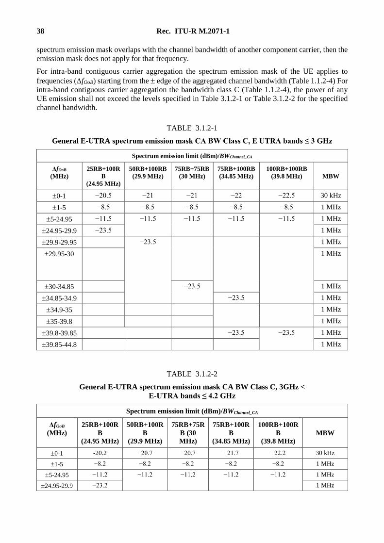
38 Rec. ITU-R M.2071-1
spectrum emission mask overlaps with the channel bandwidth of another component carrier, then the
emission mask does not apply for that frequency.
For intra-band contiguous carrier aggregation the spectrum emission mask of the UE applies to
frequencies (ΔfOoB) starting from the edge of the aggregated channel bandwidth (Table 1.1.2-4) For
intra-band contiguous carrier aggregation the bandwidth class C (Table 1.1.2-4), the power of any
UE emission shall not exceed the levels specified in Table 3.1.2-1 or Table 3.1.2-2 for the specified
channel bandwidth.
TABLE 3.1.2-1
General E-UTRA spectrum emission mask CA BW Class C, E UTRA bands ≤ 3 GHz
Spectrum emission limit (dBm)/BWChannel_CA
ΔfOoB
(MHz)
25RB+100R
B
(24.95 MHz)
50RB+100RB
(29.9 MHz)
75RB+75RB
(30 MHz)
75RB+100RB
(34.85 MHz)
100RB+100RB
(39.8 MHz) MBW
0-1 −20.5 −21 −21 −22 −22.5 30 kHz
1-5 −8.5 −8.5 −8.5 −8.5 −8.5 1 MHz
5-24.95 −11.5 −11.5 −11.5 −11.5 −11.5 1 MHz
24.95-29.9 −23.5 1 MHz
29.9-29.95 −23.5 1 MHz
29.95-30 1 MHz
30-34.85 −23.5 1 MHz
34.85-34.9 −23.5 1 MHz
34.9-35 1 MHz
35-39.8 1 MHz
39.8-39.85 −23.5 −23.5 1 MHz
39.85-44.8 1 MHz
TABLE 3.1.2-2
General E-UTRA spectrum emission mask CA BW Class C, 3GHz <
E-UTRA bands ≤ 4.2 GHz
Spectrum emission limit (dBm)/BWChannel_CA
ΔfOoB
(MHz)
25RB+100R
B
(24.95 MHz)
50RB+100R
B
(29.9 MHz)
75RB+75R
B (30
MHz)
75RB+100R
B
(34.85 MHz)
100RB+100R
B
(39.8 MHz)
MBW
0-1 -20.2 −20.7 −20.7 −21.7 −22.2 30 kHz
1-5 −8.2 −8.2 −8.2 −8.2 −8.2 1 MHz
5-24.95 −11.2 −11.2 −11.2 −11.2 −11.2 1 MHz
24.95-29.9 −23.2 1 MHz
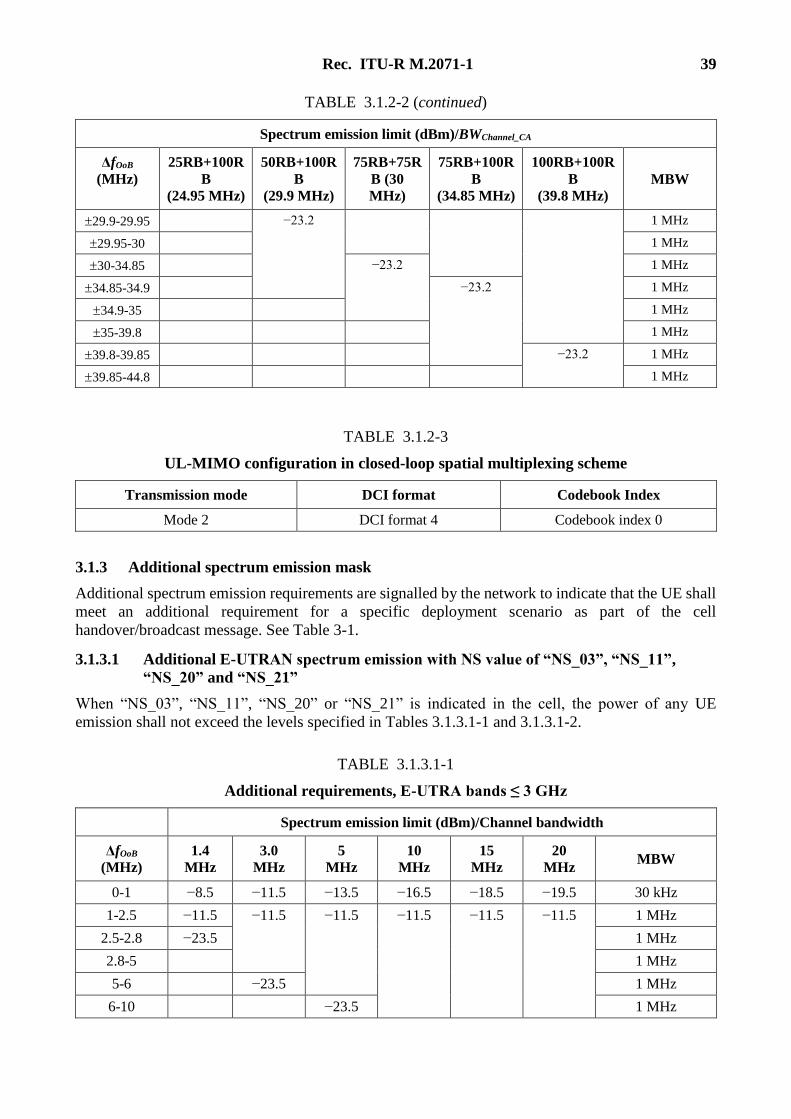
Rec. ITU-R M.2071-1 39
TABLE 3.1.2-2 (continued)
Spectrum emission limit (dBm)/BWChannel_CA
ΔfOoB
(MHz)
25RB+100R
B
(24.95 MHz)
50RB+100R
B
(29.9 MHz)
75RB+75R
B (30
MHz)
75RB+100R
B
(34.85 MHz)
100RB+100R
B
(39.8 MHz)
MBW
29.9-29.95 −23.2 1 MHz
29.95-30 1 MHz
30-34.85 −23.2 1 MHz
34.85-34.9 −23.2 1 MHz
34.9-35 1 MHz
35-39.8 1 MHz
39.8-39.85 −23.2 1 MHz
39.85-44.8 1 MHz
TABLE 3.1.2-3
UL-MIMO configuration in closed-loop spatial multiplexing scheme
Transmission mode DCI format Codebook Index
Mode 2 DCI format 4 Codebook index 0
3.1.3 Additional spectrum emission mask
Additional spectrum emission requirements are signalled by the network to indicate that the UE shall
meet an additional requirement for a specific deployment scenario as part of the cell
handover/broadcast message. See Table 3-1.
3.1.3.1 Additional E-UTRAN spectrum emission with NS value of “NS_03”, “NS_11”,
“NS_20” and “NS_21”
When “NS_03”, “NS_11”, “NS_20” or “NS_21” is indicated in the cell, the power of any UE
emission shall not exceed the levels specified in Tables 3.1.3.1-1 and 3.1.3.1-2.
TABLE 3.1.3.1-1
Additional requirements, E-UTRA bands ≤ 3 GHz
Spectrum emission limit (dBm)/Channel bandwidth
ΔfOoB
(MHz)
1.4
MHz
3.0
MHz
5
MHz
10
MHz
15
MHz
20
MHz MBW
0-1 −8.5 −11.5 −13.5 −16.5 −18.5 −19.5 30 kHz
1-2.5 −11.5 −11.5 −11.5 −11.5 −11.5 −11.5 1 MHz
2.5-2.8 −23.5 1 MHz
2.8-5 1 MHz
5-6 −23.5 1 MHz
6-10 −23.5 1 MHz
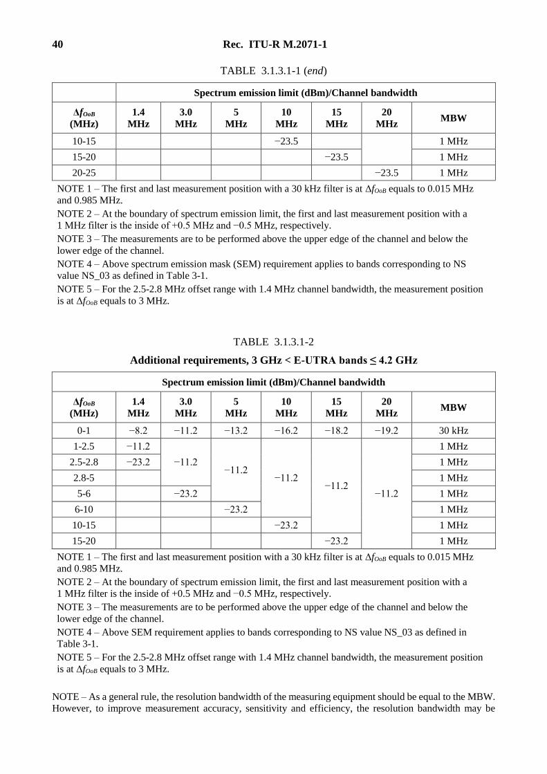
40 Rec. ITU-R M.2071-1
TABLE 3.1.3.1-1 (end)
Spectrum emission limit (dBm)/Channel bandwidth
ΔfOoB
(MHz)
1.4
MHz
3.0
MHz
5
MHz
10
MHz
15
MHz
20
MHz MBW
10-15 −23.5 1 MHz
15-20 −23.5 1 MHz
20-25 −23.5 1 MHz
NOTE 1 – The first and last measurement position with a 30 kHz filter is at ΔfOoB equals to 0.015 MHz
and 0.985 MHz.
NOTE 2 – At the boundary of spectrum emission limit, the first and last measurement position with a
1 MHz filter is the inside of +0.5 MHz and −0.5 MHz, respectively.
NOTE 3 – The measurements are to be performed above the upper edge of the channel and below the
lower edge of the channel.
NOTE 4 – Above spectrum emission mask (SEM) requirement applies to bands corresponding to NS
value NS_03 as defined in Table 3-1.
NOTE 5 – For the 2.5-2.8 MHz offset range with 1.4 MHz channel bandwidth, the measurement position
is at ΔfOoB equals to 3 MHz.
TABLE 3.1.3.1-2
Additional requirements, 3 GHz < E-UTRA bands ≤ 4.2 GHz
Spectrum emission limit (dBm)/Channel bandwidth
ΔfOoB
(MHz)
1.4
MHz
3.0
MHz
5
MHz
10
MHz
15
MHz
20
MHz MBW
0-1 −8.2 −11.2 −13.2 −16.2 −18.2 −19.2 30 kHz
1-2.5 −11.2
−11.2 −11.2
−11.2 −11.2
−11.2
1 MHz
2.5-2.8 −23.2 1 MHz
2.8-5 1 MHz
5-6 −23.2 1 MHz
6-10 −23.2 1 MHz
10-15 −23.2 1 MHz
15-20 −23.2 1 MHz
NOTE 1 – The first and last measurement position with a 30 kHz filter is at ΔfOoB equals to 0.015 MHz
and 0.985 MHz.
NOTE 2 – At the boundary of spectrum emission limit, the first and last measurement position with a
1 MHz filter is the inside of +0.5 MHz and −0.5 MHz, respectively.
NOTE 3 – The measurements are to be performed above the upper edge of the channel and below the
lower edge of the channel.
NOTE 4 – Above SEM requirement applies to bands corresponding to NS value NS_03 as defined in
Table 3-1.
NOTE 5 – For the 2.5-2.8 MHz offset range with 1.4 MHz channel bandwidth, the measurement position
is at ΔfOoB equals to 3 MHz.
NOTE – As a general rule, the resolution bandwidth of the measuring equipment should be equal to the MBW.
However, to improve measurement accuracy, sensitivity and efficiency, the resolution bandwidth may be
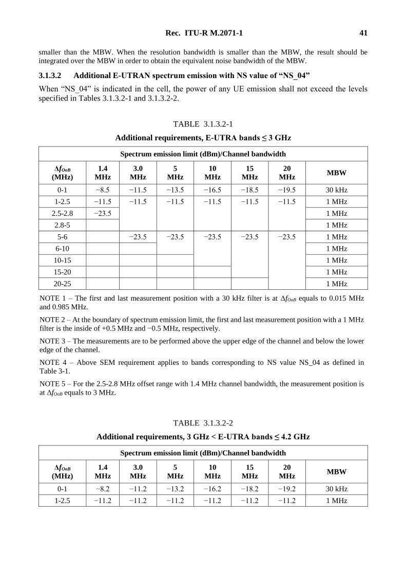
Rec. ITU-R M.2071-1 41
smaller than the MBW. When the resolution bandwidth is smaller than the MBW, the result should be
integrated over the MBW in order to obtain the equivalent noise bandwidth of the MBW.
3.1.3.2 Additional E-UTRAN spectrum emission with NS value of “NS_04”
When “NS_04” is indicated in the cell, the power of any UE emission shall not exceed the levels
specified in Tables 3.1.3.2-1 and 3.1.3.2-2.
TABLE 3.1.3.2-1
Additional requirements, E-UTRA bands ≤ 3 GHz
Spectrum emission limit (dBm)/Channel bandwidth
ΔfOoB
(MHz)
1.4
MHz
3.0
MHz
5
MHz
10
MHz
15
MHz
20
MHz MBW
0-1 −8.5 −11.5 −13.5 −16.5 −18.5 −19.5 30 kHz
1-2.5 −11.5 −11.5 −11.5 −11.5 −11.5 −11.5 1 MHz
2.5-2.8 −23.5 1 MHz
2.8-5 1 MHz
5-6 −23.5 −23.5 −23.5 −23.5 −23.5 1 MHz
6-10 1 MHz
10-15 1 MHz
15-20 1 MHz
20-25 1 MHz
NOTE 1 – The first and last measurement position with a 30 kHz filter is at ΔfOoB equals to 0.015 MHz
and 0.985 MHz.
NOTE 2 – At the boundary of spectrum emission limit, the first and last measurement position with a 1 MHz
filter is the inside of +0.5 MHz and −0.5 MHz, respectively.
NOTE 3 – The measurements are to be performed above the upper edge of the channel and below the lower
edge of the channel.
NOTE 4 – Above SEM requirement applies to bands corresponding to NS value NS_04 as defined in
Table 3-1.
NOTE 5 – For the 2.5-2.8 MHz offset range with 1.4 MHz channel bandwidth, the measurement position is
at ΔfOoB equals to 3 MHz.
TABLE 3.1.3.2-2
Additional requirements, 3 GHz < E-UTRA bands ≤ 4.2 GHz
Spectrum emission limit (dBm)/Channel bandwidth
ΔfOoB
(MHz)
1.4
MHz
3.0
MHz
5
MHz
10
MHz
15
MHz
20
MHz MBW
0-1 −8.2 −11.2 −13.2 −16.2 −18.2 −19.2 30 kHz
1-2.5 −11.2 −11.2 −11.2 −11.2 −11.2 −11.2 1 MHz
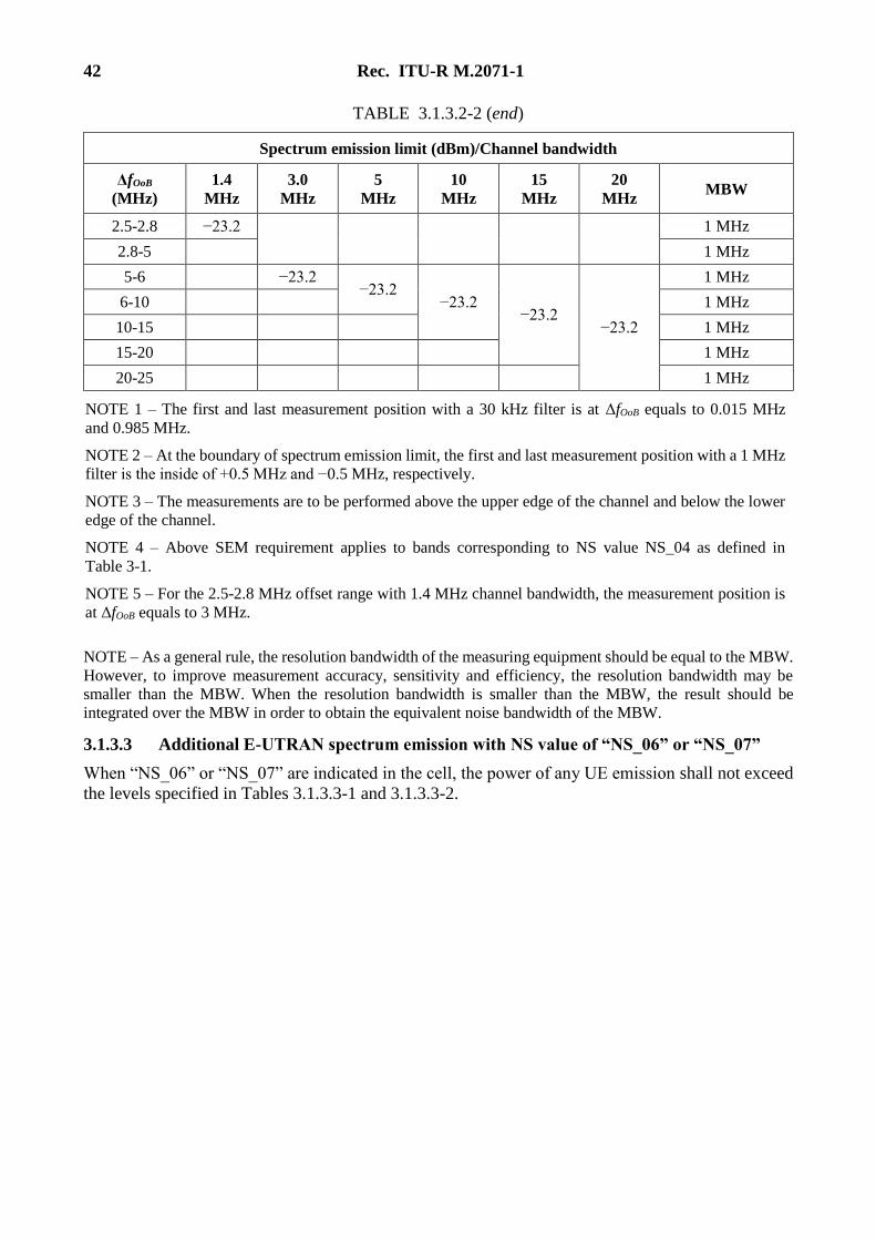
42 Rec. ITU-R M.2071-1
TABLE 3.1.3.2-2 (end)
Spectrum emission limit (dBm)/Channel bandwidth
ΔfOoB
(MHz)
1.4
MHz
3.0
MHz
5
MHz
10
MHz
15
MHz
20
MHz MBW
2.5-2.8 −23.2
1 MHz
2.8-5 1 MHz
5-6 −23.2 −23.2
−23.2 −23.2
−23.2
1 MHz
6-10 1 MHz
10-15 1 MHz
15-20 1 MHz
20-25 1 MHz
NOTE 1 – The first and last measurement position with a 30 kHz filter is at ΔfOoB equals to 0.015 MHz
and 0.985 MHz.
NOTE 2 – At the boundary of spectrum emission limit, the first and last measurement position with a 1 MHz
filter is the inside of +0.5 MHz and −0.5 MHz, respectively.
NOTE 3 – The measurements are to be performed above the upper edge of the channel and below the lower
edge of the channel.
NOTE 4 – Above SEM requirement applies to bands corresponding to NS value NS_04 as defined in
Table 3-1.
NOTE 5 – For the 2.5-2.8 MHz offset range with 1.4 MHz channel bandwidth, the measurement position is
at ΔfOoB equals to 3 MHz.
NOTE – As a general rule, the resolution bandwidth of the measuring equipment should be equal to the MBW.
However, to improve measurement accuracy, sensitivity and efficiency, the resolution bandwidth may be
smaller than the MBW. When the resolution bandwidth is smaller than the MBW, the result should be
integrated over the MBW in order to obtain the equivalent noise bandwidth of the MBW.
3.1.3.3 Additional E-UTRAN spectrum emission with NS value of “NS_06” or “NS_07”
When “NS_06” or “NS_07” are indicated in the cell, the power of any UE emission shall not exceed
the levels specified in Tables 3.1.3.3-1 and 3.1.3.3-2.
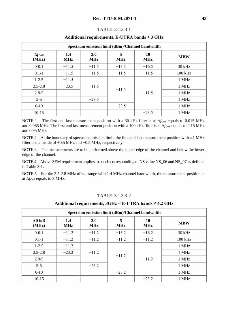
Rec. ITU-R M.2071-1 43
TABLE 3.1.3.3-1
Additional requirements, E-UTRA bands ≤ 3 GHz
Spectrum emission limit (dBm)/Channel bandwidth
ΔfOoB
(MHz)
1.4
MHz
3.0
MHz
5
MHz
10
MHz MBW
0-0.1 −11.5 −11.5 −13.5 −16.5 30 kHz
0.1-1 −11.5 −11.5 −11.5 −11.5 100 kHz
1-2.5 −11.5
−11.5 −11.5
−11.5
1 MHz
2.5-2.8 −23.5 1 MHz
2.8-5 1 MHz
5-6 −23.5 1 MHz
6-10 −23.5 1 MHz
10-15 −23.5 1 MHz
NOTE 1 – The first and last measurement position with a 30 kHz filter is at ΔfOoB equals to 0.015 MHz
and 0.085 MHz. The first and last measurement position with a 100 kHz filter is at ΔfOoB equals to 0.15 MHz
and 0.95 MHz.
NOTE 2 – At the boundary of spectrum emission limit, the first and last measurement position with a 1 MHz
filter is the inside of +0.5 MHz and −0.5 MHz, respectively.
NOTE 3 – The measurements are to be performed above the upper edge of the channel and below the lower
edge of the channel.
NOTE 4 – Above SEM requirement applies to bands corresponding to NS value NS_06 and NS_07 as defined
in Table 3-1.
NOTE 5 – For the 2.5-2.8 MHz offset range with 1.4 MHz channel bandwidth, the measurement position is
at ΔfOoB equals to 3 MHz.
TABLE 3.1.3.3-2
Additional requirements, 3GHz < E-UTRA bands ≤ 4.2 GHz
Spectrum emission limit (dBm)/Channel bandwidth
ΔfOoB
(MHz)
1.4
MHz
3.0
MHz
5
MHz
10
MHz MBW
0-0.1 −11.2 −11.2 −13.2 −16.2 30 kHz
0.1-1 −11.2 −11.2 −11.2 −11.2 100 kHz
1-2.5 −11.2
−11.2 −11.2
−11.2
1 MHz
2.5-2.8 −23.2 1 MHz
2.8-5 1 MHz
5-6 −23.2 1 MHz
6-10 −23.2 1 MHz
10-15 −23.2 1 MHz
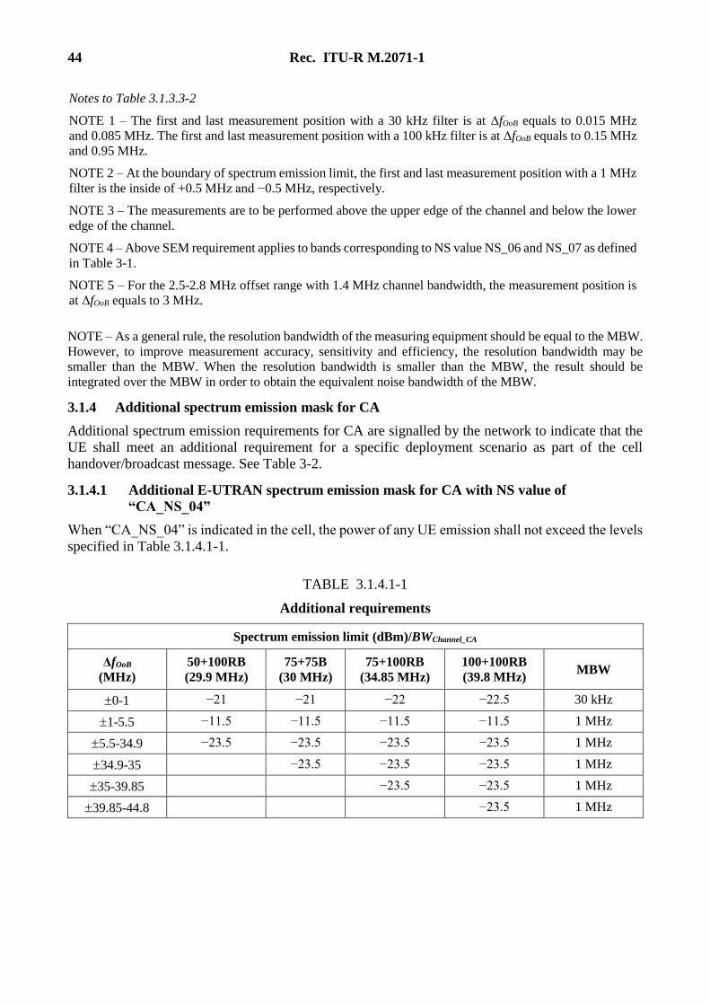
44 Rec. ITU-R M.2071-1
Notes to Table 3.1.3.3-2
NOTE 1 – The first and last measurement position with a 30 kHz filter is at ΔfOoB equals to 0.015 MHz
and 0.085 MHz. The first and last measurement position with a 100 kHz filter is at ΔfOoB equals to 0.15 MHz
and 0.95 MHz.
NOTE 2 – At the boundary of spectrum emission limit, the first and last measurement position with a 1 MHz
filter is the inside of +0.5 MHz and −0.5 MHz, respectively.
NOTE 3 – The measurements are to be performed above the upper edge of the channel and below the lower
edge of the channel.
NOTE 4 – Above SEM requirement applies to bands corresponding to NS value NS_06 and NS_07 as defined
in Table 3-1.
NOTE 5 – For the 2.5-2.8 MHz offset range with 1.4 MHz channel bandwidth, the measurement position is
at ΔfOoB equals to 3 MHz.
NOTE – As a general rule, the resolution bandwidth of the measuring equipment should be equal to the MBW.
However, to improve measurement accuracy, sensitivity and efficiency, the resolution bandwidth may be
smaller than the MBW. When the resolution bandwidth is smaller than the MBW, the result should be
integrated over the MBW in order to obtain the equivalent noise bandwidth of the MBW.
3.1.4 Additional spectrum emission mask for CA
Additional spectrum emission requirements for CA are signalled by the network to indicate that the
UE shall meet an additional requirement for a specific deployment scenario as part of the cell
handover/broadcast message. See Table 3-2.
3.1.4.1 Additional E-UTRAN spectrum emission mask for CA with NS value of
“CA_NS_04”
When “CA_NS_04” is indicated in the cell, the power of any UE emission shall not exceed the levels
specified in Table 3.1.4.1-1.
TABLE 3.1.4.1-1
Additional requirements
Spectrum emission limit (dBm)/BWChannel_CA
ΔfOoB
(MHz)
50+100RB
(29.9 MHz)
75+75B
(30 MHz)
75+100RB
(34.85 MHz)
100+100RB
(39.8 MHz) MBW
0-1 −21 −21 −22 −22.5 30 kHz
1-5.5 −11.5 −11.5 −11.5 −11.5 1 MHz
5.5-34.9 −23.5 −23.5 −23.5 −23.5 1 MHz
34.9-35 −23.5 −23.5 −23.5 1 MHz
35-39.85 −23.5 −23.5 1 MHz
39.85-44.8 −23.5 1 MHz
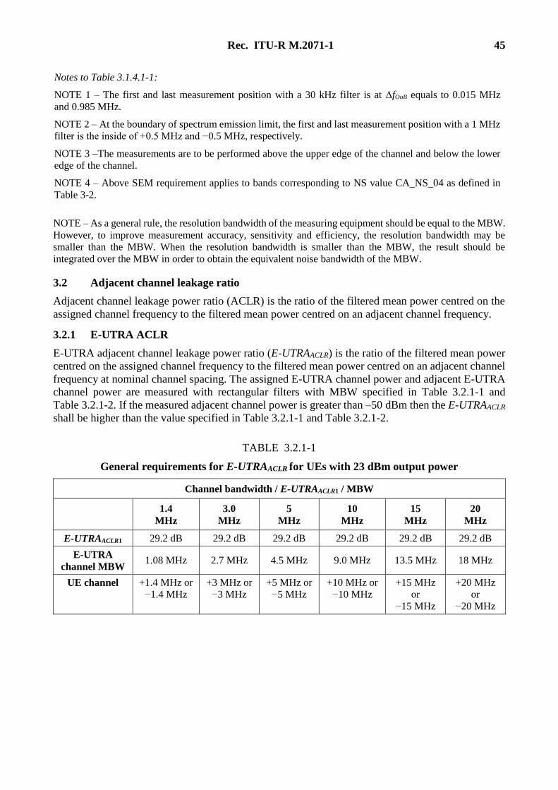
Rec. ITU-R M.2071-1 45
Notes to Table 3.1.4.1-1:
NOTE 1 – The first and last measurement position with a 30 kHz filter is at ΔfOoB equals to 0.015 MHz
and 0.985 MHz.
NOTE 2 – At the boundary of spectrum emission limit, the first and last measurement position with a 1 MHz
filter is the inside of +0.5 MHz and −0.5 MHz, respectively.
NOTE 3 –The measurements are to be performed above the upper edge of the channel and below the lower
edge of the channel.
NOTE 4 – Above SEM requirement applies to bands corresponding to NS value CA_NS_04 as defined in
Table 3-2.
NOTE – As a general rule, the resolution bandwidth of the measuring equipment should be equal to the MBW.
However, to improve measurement accuracy, sensitivity and efficiency, the resolution bandwidth may be
smaller than the MBW. When the resolution bandwidth is smaller than the MBW, the result should be
integrated over the MBW in order to obtain the equivalent noise bandwidth of the MBW.
3.2 Adjacent channel leakage ratio
Adjacent channel leakage power ratio (ACLR) is the ratio of the filtered mean power centred on the
assigned channel frequency to the filtered mean power centred on an adjacent channel frequency.
3.2.1 E-UTRA ACLR
E-UTRA adjacent channel leakage power ratio (E-UTRAACLR) is the ratio of the filtered mean power
centred on the assigned channel frequency to the filtered mean power centred on an adjacent channel
frequency at nominal channel spacing. The assigned E-UTRA channel power and adjacent E-UTRA
channel power are measured with rectangular filters with MBW specified in Table 3.2.1-1 and
Table 3.2.1-2. If the measured adjacent channel power is greater than –50 dBm then the E-UTRAACLR
shall be higher than the value specified in Table 3.2.1-1 and Table 3.2.1-2.
TABLE 3.2.1-1
General requirements for E-UTRAACLR for UEs with 23 dBm output power
Channel bandwidth / E-UTRAACLR1 / MBW
1.4
MHz
3.0
MHz
5
MHz
10
MHz
15
MHz
20
MHz
E-UTRAACLR1 29.2 dB 29.2 dB 29.2 dB 29.2 dB 29.2 dB 29.2 dB
E-UTRA
channel MBW 1.08 MHz 2.7 MHz 4.5 MHz 9.0 MHz 13.5 MHz 18 MHz
UE channel +1.4 MHz or
−1.4 MHz
+3 MHz or
−3 MHz
+5 MHz or
−5 MHz
+10 MHz or
−10 MHz
+15 MHz
or
−15 MHz
+20 MHz
or
−20 MHz
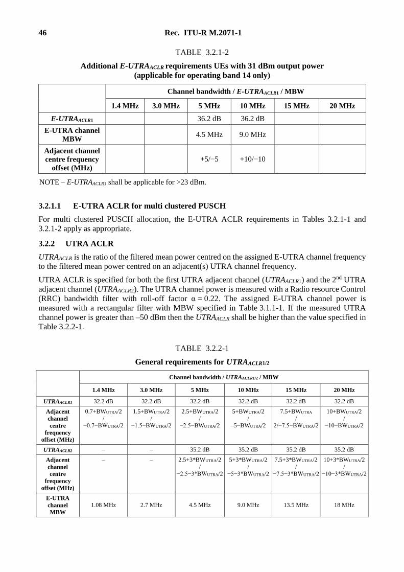
46 Rec. ITU-R M.2071-1
TABLE 3.2.1-2
Additional E-UTRAACLR requirements UEs with 31 dBm output power
(applicable for operating band 14 only)
Channel bandwidth / E-UTRAACLR1 / MBW
1.4 MHz 3.0 MHz 5 MHz 10 MHz 15 MHz 20 MHz
E-UTRAACLR1 36.2 dB 36.2 dB
E-UTRA channel
MBW 4.5 MHz 9.0 MHz
Adjacent channel
centre frequency
offset (MHz)
+5/−5 +10/−10
NOTE – E-UTRAACLR1 shall be applicable for >23 dBm.
3.2.1.1 E-UTRA ACLR for multi clustered PUSCH
For multi clustered PUSCH allocation, the E-UTRA ACLR requirements in Tables 3.2.1-1 and
3.2.1-2 apply as appropriate.
3.2.2 UTRA ACLR
UTRAACLR is the ratio of the filtered mean power centred on the assigned E-UTRA channel frequency
to the filtered mean power centred on an adjacent(s) UTRA channel frequency.
UTRA ACLR is specified for both the first UTRA adjacent channel (UTRAACLR1) and the 2nd UTRA
adjacent channel (UTRAACLR2). The UTRA channel power is measured with a Radio resource Control
(RRC) bandwidth filter with roll-off factor α = 0.22. The assigned E-UTRA channel power is
measured with a rectangular filter with MBW specified in Table 3.1.1-1. If the measured UTRA
channel power is greater than –50 dBm then the UTRAACLR shall be higher than the value specified in
Table 3.2.2-1.
TABLE 3.2.2-1
General requirements for UTRAACLR1/2
Channel bandwidth / UTRAACLR1/2 / MBW
1.4 MHz 3.0 MHz 5 MHz 10 MHz 15 MHz 20 MHz
UTRAACLR1 32.2 dB 32.2 dB 32.2 dB 32.2 dB 32.2 dB 32.2 dB
Adjacent
channel
centre
frequency
offset (MHz)
0.7+BWUTRA/2
/
−0.7−BWUTRA/2
1.5+BWUTRA/2
/
−1.5−BWUTRA/2
2.5+BWUTRA/2
/
−2.5−BWUTRA/2
5+BWUTRA/2
/
–5−BWUTRA/2
7.5+BWUTRA
/
2/−7.5−BWUTRA/2
10+BWUTRA/2
/
−10−BWUTRA/2
UTRAACLR2 – – 35.2 dB 35.2 dB 35.2 dB 35.2 dB
Adjacent
channel
centre
frequency
offset (MHz)
– – 2.5+3*BWUTRA/2
/ −2.5−3*BWUTRA/2
5+3*BWUTRA/2
/ −5−3*BWUTRA/2
7.5+3*BWUTRA/2
/ −7.5−3*BWUTRA/2
10+3*BWUTRA/2
/ −10−3*BWUTRA/2
E-UTRA
channel
MBW
1.08 MHz 2.7 MHz 4.5 MHz 9.0 MHz 13.5 MHz 18 MHz
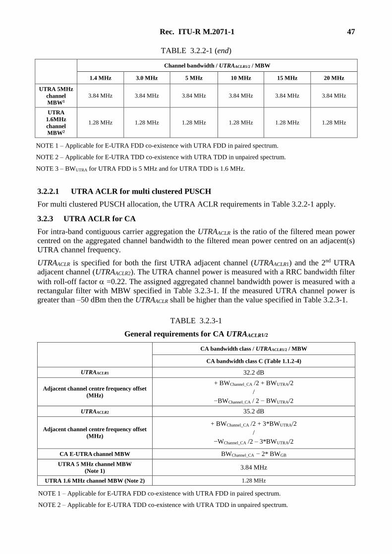
Rec. ITU-R M.2071-1 47
TABLE 3.2.2-1 (end)
Channel bandwidth / UTRAACLR1/2 / MBW
1.4 MHz 3.0 MHz 5 MHz 10 MHz 15 MHz 20 MHz
UTRA 5MHz
channel
MBW1
3.84 MHz 3.84 MHz 3.84 MHz 3.84 MHz 3.84 MHz 3.84 MHz
UTRA
1.6MHz
channel
MBW2
1.28 MHz 1.28 MHz 1.28 MHz 1.28 MHz 1.28 MHz 1.28 MHz
NOTE 1 – Applicable for E-UTRA FDD co-existence with UTRA FDD in paired spectrum.
NOTE 2 – Applicable for E-UTRA TDD co-existence with UTRA TDD in unpaired spectrum.
NOTE 3 – BWUTRA for UTRA FDD is 5 MHz and for UTRA TDD is 1.6 MHz.
3.2.2.1 UTRA ACLR for multi clustered PUSCH
For multi clustered PUSCH allocation, the UTRA ACLR requirements in Table 3.2.2-1 apply.
3.2.3 UTRA ACLR for CA
For intra-band contiguous carrier aggregation the UTRAACLR is the ratio of the filtered mean power
centred on the aggregated channel bandwidth to the filtered mean power centred on an adjacent(s)
UTRA channel frequency.
UTRAACLR is specified for both the first UTRA adjacent channel (UTRAACLR1) and the 2nd UTRA
adjacent channel (UTRAACLR2). The UTRA channel power is measured with a RRC bandwidth filter
with roll-off factor =0.22. The assigned aggregated channel bandwidth power is measured with a
rectangular filter with MBW specified in Table 3.2.3-1. If the measured UTRA channel power is
greater than –50 dBm then the UTRAACLR shall be higher than the value specified in Table 3.2.3-1.
TABLE 3.2.3-1
General requirements for CA UTRAACLR1/2
CA bandwidth class / UTRAACLR1/2 / MBW
CA bandwidth class C (Table 1.1.2-4)
UTRAACLR1 32.2 dB
Adjacent channel centre frequency offset
(MHz)
+ BWChannel_CA /2 + BWUTRA/2
/
−BWChannel_CA / 2 − BWUTRA/2
UTRAACLR2 35.2 dB
Adjacent channel centre frequency offset
(MHz)
+ BWChannel_CA /2 + 3*BWUTRA/2
/
−WChannel_CA /2 – 3*BWUTRA/2
CA E-UTRA channel MBW BWChannel_CA − 2* BWGB
UTRA 5 MHz channel MBW
(Note 1) 3.84 MHz
UTRA 1.6 MHz channel MBW (Note 2) 1.28 MHz
NOTE 1 – Applicable for E-UTRA FDD co-existence with UTRA FDD in paired spectrum.
NOTE 2 – Applicable for E-UTRA TDD co-existence with UTRA TDD in unpaired spectrum.
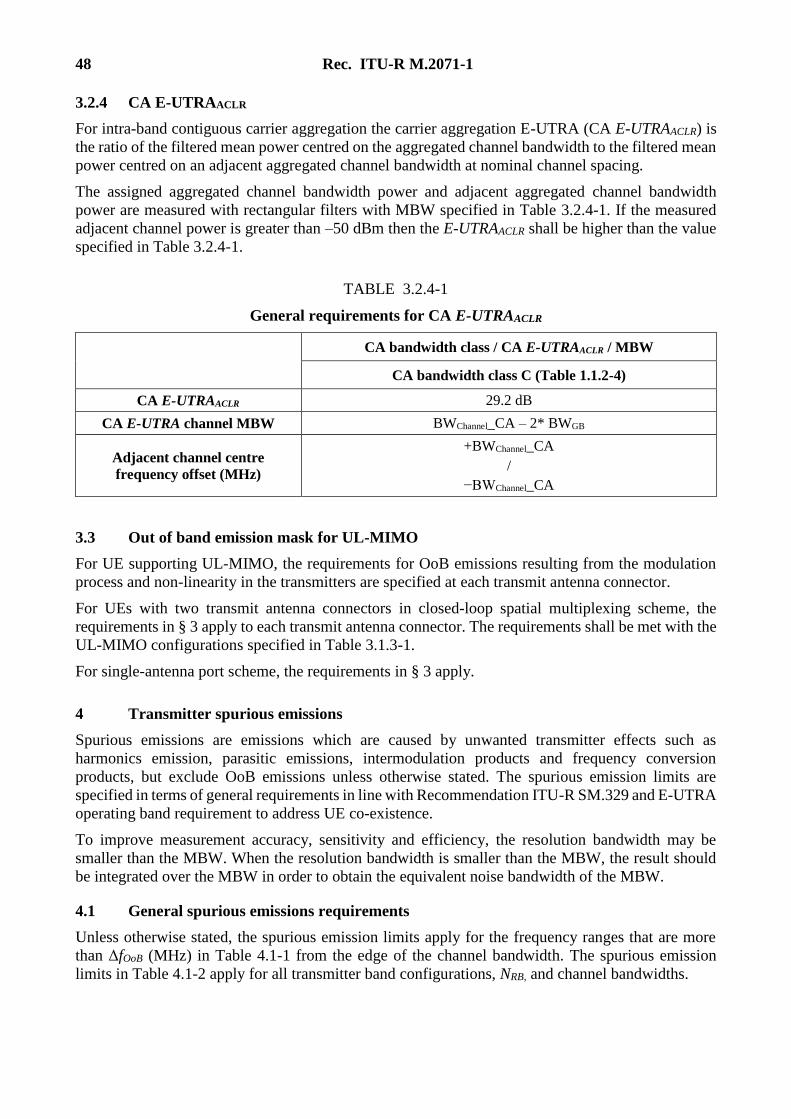
48 Rec. ITU-R M.2071-1
3.2.4 CA E-UTRAACLR
For intra-band contiguous carrier aggregation the carrier aggregation E-UTRA (CA E-UTRAACLR) is
the ratio of the filtered mean power centred on the aggregated channel bandwidth to the filtered mean
power centred on an adjacent aggregated channel bandwidth at nominal channel spacing.
The assigned aggregated channel bandwidth power and adjacent aggregated channel bandwidth
power are measured with rectangular filters with MBW specified in Table 3.2.4-1. If the measured
adjacent channel power is greater than –50 dBm then the E-UTRAACLR shall be higher than the value
specified in Table 3.2.4-1.
TABLE 3.2.4-1
General requirements for CA E-UTRAACLR
CA bandwidth class / CA E-UTRAACLR / MBW
CA bandwidth class C (Table 1.1.2-4)
CA E-UTRAACLR 29.2 dB
CA E-UTRA channel MBW BWChannel_CA – 2* BWGB
Adjacent channel centre
frequency offset (MHz)
+BWChannel_CA
/
−BWChannel_CA
3.3 Out of band emission mask for UL-MIMO
For UE supporting UL-MIMO, the requirements for OoB emissions resulting from the modulation
process and non-linearity in the transmitters are specified at each transmit antenna connector.
For UEs with two transmit antenna connectors in closed-loop spatial multiplexing scheme, the
requirements in § 3 apply to each transmit antenna connector. The requirements shall be met with the
UL-MIMO configurations specified in Table 3.1.3-1.
For single-antenna port scheme, the requirements in § 3 apply.
4 Transmitter spurious emissions
Spurious emissions are emissions which are caused by unwanted transmitter effects such as
harmonics emission, parasitic emissions, intermodulation products and frequency conversion
products, but exclude OoB emissions unless otherwise stated. The spurious emission limits are
specified in terms of general requirements in line with Recommendation ITU-R SM.329 and E-UTRA
operating band requirement to address UE co-existence.
To improve measurement accuracy, sensitivity and efficiency, the resolution bandwidth may be
smaller than the MBW. When the resolution bandwidth is smaller than the MBW, the result should
be integrated over the MBW in order to obtain the equivalent noise bandwidth of the MBW.
4.1 General spurious emissions requirements
Unless otherwise stated, the spurious emission limits apply for the frequency ranges that are more
than ΔfOoB (MHz) in Table 4.1-1 from the edge of the channel bandwidth. The spurious emission
limits in Table 4.1-2 apply for all transmitter band configurations, NRB, and channel bandwidths.
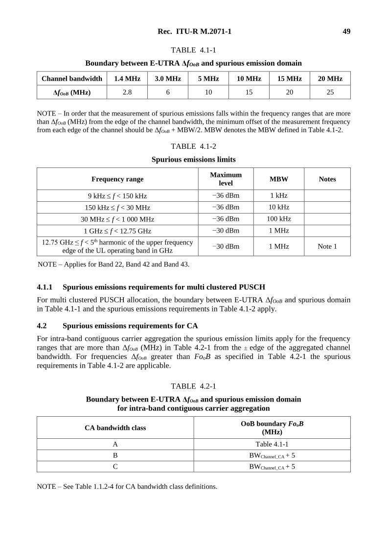
Rec. ITU-R M.2071-1 49
TABLE 4.1-1
Boundary between E-UTRA ΔfOoB and spurious emission domain
Channel bandwidth 1.4 MHz 3.0 MHz 5 MHz 10 MHz 15 MHz 20 MHz
ΔfOoB (MHz) 2.8 6 10 15 20 25
NOTE – In order that the measurement of spurious emissions falls within the frequency ranges that are more
than ΔfOoB (MHz) from the edge of the channel bandwidth, the minimum offset of the measurement frequency
from each edge of the channel should be ΔfOoB + MBW/2. MBW denotes the MBW defined in Table 4.1-2.
TABLE 4.1-2
Spurious emissions limits
Frequency range Maximum
level MBW Notes
9 kHz f < 150 kHz −36 dBm 1 kHz
150 kHz f < 30 MHz −36 dBm 10 kHz
30 MHz f < 1 000 MHz −36 dBm 100 kHz
1 GHz f < 12.75 GHz −30 dBm 1 MHz
12.75 GHz ≤ f < 5th harmonic of the upper frequency
edge of the UL operating band in GHz −30 dBm 1 MHz Note 1
NOTE – Applies for Band 22, Band 42 and Band 43.
4.1.1 Spurious emissions requirements for multi clustered PUSCH
For multi clustered PUSCH allocation, the boundary between E-UTRA ΔfOoB and spurious domain
in Table 4.1-1 and the spurious emissions requirements in Table 4.1-2 apply.
4.2 Spurious emissions requirements for CA
For intra-band contiguous carrier aggregation the spurious emission limits apply for the frequency
ranges that are more than ΔfOoB (MHz) in Table 4.2-1 from the edge of the aggregated channel
bandwidth. For frequencies ΔfOoB greater than FooB as specified in Table 4.2-1 the spurious
requirements in Table 4.1-2 are applicable.
TABLE 4.2-1
Boundary between E-UTRA ΔfOoB and spurious emission domain
for intra-band contiguous carrier aggregation
CA bandwidth class OoB boundary FooB
(MHz)
A Table 4.1-1
B BWChannel_CA + 5
C BWChannel_CA + 5
NOTE – See Table 1.1.2-4 for CA bandwidth class definitions.
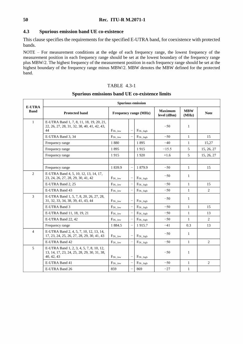
50 Rec. ITU-R M.2071-1
4.3 Spurious emission band UE co-existence
This clause specifies the requirements for the specified E-UTRA band, for coexistence with protected
bands.
NOTE – For measurement conditions at the edge of each frequency range, the lowest frequency of the
measurement position in each frequency range should be set at the lowest boundary of the frequency range
plus MBW/2. The highest frequency of the measurement position in each frequency range should be set at the
highest boundary of the frequency range minus MBW/2. MBW denotes the MBW defined for the protected
band.
TABLE 4.3-1
Spurious emissions band UE co-existence limits
E-UTRA
Band
Spurious emission
Protected band Frequency range (MHz) Maximum
level (dBm)
MBW
(MHz) Note
1 E-UTRA Band 1, 7, 8, 11, 18, 19, 20, 21,
22, 26, 27, 28, 31, 32, 38, 40, 41, 42, 43, 44 FDL_low − FDL_high
−50 1
E-UTRA Band 3, 34 FDL_low − FDL_high −50 1 15
Frequency range 1 880 1 895 −40 1 15,27
Frequency range 1 895 1 915 −15.5 5 15, 26, 27
Frequency range 1 915 1 920 +1.6 5 15, 26, 27
Frequency range 1 839.9 − 1 879.9 −50 1 15
2 E-UTRA Band 4, 5, 10, 12, 13, 14, 17,
23, 24, 26, 27, 28, 29, 30, 41, 42 FDL_low − FDL_high −50 1
E-UTRA Band 2, 25 FDL_low − FDL_high −50 1 15
E-UTRA Band 43 FDL_low − FDL_high −50 1 2
3 E-UTRA Band 1, 5, 7, 8, 20, 26, 27, 28,
31, 32, 33, 34, 38, 39, 41, 43, 44 FDL_low − FDL_high −50 1
E-UTRA Band 3 FDL_low − FDL_high −50 1 15
E-UTRA Band 11, 18, 19, 21 FDL_low − FDL_high −50 1 13
E-UTRA Band 22, 42 FDL_low − FDL_high −50 1 2
Frequency range 1 884.5 − 1 915.7 −41 0.3 13
4 E-UTRA Band 2, 4, 5, 7, 10, 12, 13, 14,
17, 23, 24, 25, 26, 27, 28, 29, 30, 41, 43 FDL_low − FDL_high −50 1
E-UTRA Band 42 FDL_low − FDL_high −50 1 2
5 E-UTRA Band 1, 2, 3, 4, 5, 7, 8, 10, 12,
13, 14, 17, 23, 24, 25, 28, 29, 30, 31, 38, 40, 42, 43 FDL_low − FDL_high
−50 1
E-UTRA Band 41 FDL_low − FDL_high −50 1 2
E-UTRA Band 26 859 − 869 −27 1
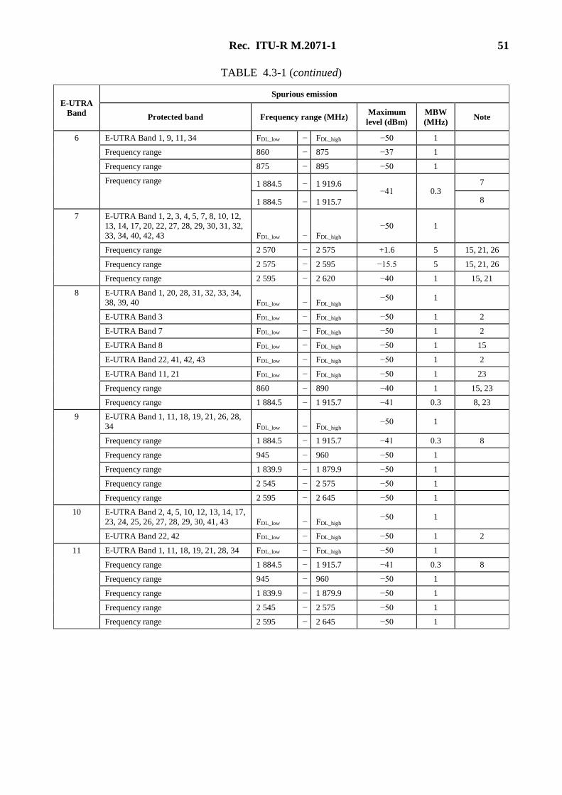
Rec. ITU-R M.2071-1 51
TABLE 4.3-1 (continued)
E-UTRA
Band
Spurious emission
Protected band Frequency range (MHz) Maximum
level (dBm)
MBW
(MHz) Note
6 E-UTRA Band 1, 9, 11, 34 FDL_low − FDL_high −50 1
Frequency range 860 − 875 −37 1
Frequency range 875 − 895 −50 1
Frequency range 1 884.5 − 1 919.6 −41 0.3
7
1 884.5 − 1 915.7 8
7 E-UTRA Band 1, 2, 3, 4, 5, 7, 8, 10, 12,
13, 14, 17, 20, 22, 27, 28, 29, 30, 31, 32,
33, 34, 40, 42, 43 FDL_low − FDL_high
−50 1
Frequency range 2 570 − 2 575 +1.6 5 15, 21, 26
Frequency range 2 575 − 2 595 −15.5 5 15, 21, 26
Frequency range 2 595 − 2 620 −40 1 15, 21
8 E-UTRA Band 1, 20, 28, 31, 32, 33, 34,
38, 39, 40 FDL_low − FDL_high −50 1
E-UTRA Band 3 FDL_low − FDL_high −50 1 2
E-UTRA Band 7 FDL_low − FDL_high −50 1 2
E-UTRA Band 8 FDL_low − FDL_high −50 1 15
E-UTRA Band 22, 41, 42, 43 FDL_low − FDL_high −50 1 2
E-UTRA Band 11, 21 FDL_low − FDL_high −50 1 23
Frequency range 860 − 890 −40 1 15, 23
Frequency range 1 884.5 − 1 915.7 −41 0.3 8, 23
9 E-UTRA Band 1, 11, 18, 19, 21, 26, 28,
34 FDL_low − FDL_high −50 1
Frequency range 1 884.5 − 1 915.7 −41 0.3 8
Frequency range 945 − 960 −50 1
Frequency range 1 839.9 − 1 879.9 −50 1
Frequency range 2 545 − 2 575 −50 1
Frequency range 2 595 − 2 645 −50 1
10 E-UTRA Band 2, 4, 5, 10, 12, 13, 14, 17,
23, 24, 25, 26, 27, 28, 29, 30, 41, 43 FDL_low − FDL_high −50 1
E-UTRA Band 22, 42 FDL_low − FDL_high −50 1 2
11 E-UTRA Band 1, 11, 18, 19, 21, 28, 34 FDL_low − FDL_high −50 1
Frequency range 1 884.5 − 1 915.7 −41 0.3 8
Frequency range 945 − 960 −50 1
Frequency range 1 839.9 − 1 879.9 −50 1
Frequency range 2 545 − 2 575 −50 1
Frequency range 2 595 − 2 645 −50 1
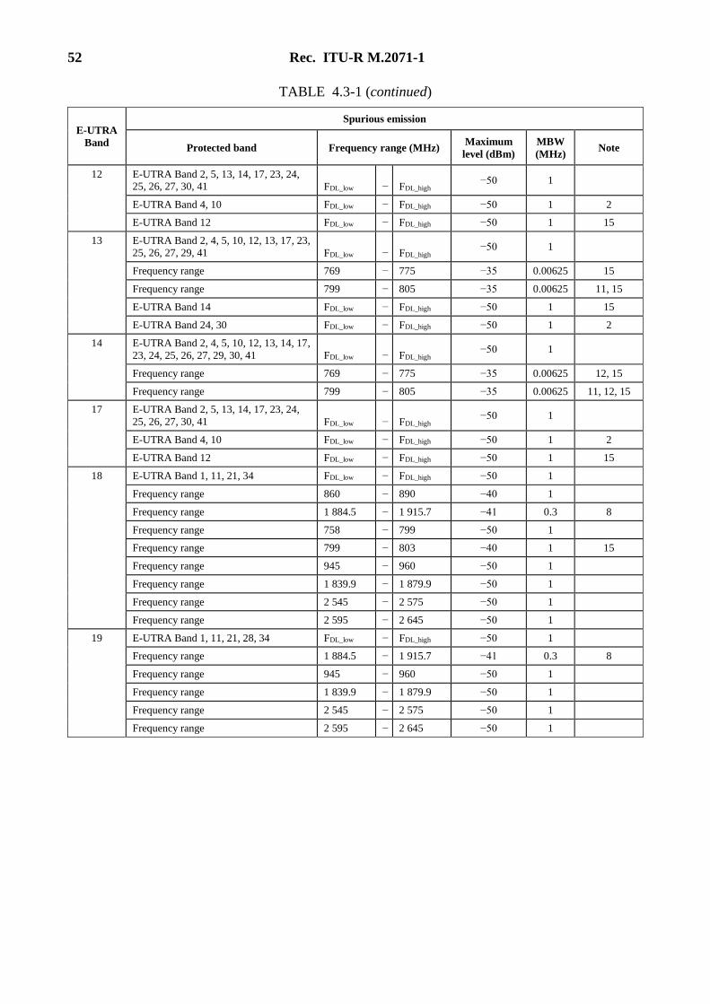
52 Rec. ITU-R M.2071-1
TABLE 4.3-1 (continued)
E-UTRA
Band
Spurious emission
Protected band Frequency range (MHz) Maximum
level (dBm)
MBW
(MHz) Note
12 E-UTRA Band 2, 5, 13, 14, 17, 23, 24, 25, 26, 27, 30, 41 FDL_low − FDL_high
−50 1
E-UTRA Band 4, 10 FDL_low − FDL_high −50 1 2
E-UTRA Band 12 FDL_low − FDL_high −50 1 15
13 E-UTRA Band 2, 4, 5, 10, 12, 13, 17, 23,
25, 26, 27, 29, 41 FDL_low − FDL_high −50 1
Frequency range 769 − 775 −35 0.00625 15
Frequency range 799 − 805 −35 0.00625 11, 15
E-UTRA Band 14 FDL_low − FDL_high −50 1 15
E-UTRA Band 24, 30 FDL_low − FDL_high −50 1 2
14 E-UTRA Band 2, 4, 5, 10, 12, 13, 14, 17,
23, 24, 25, 26, 27, 29, 30, 41 FDL_low − FDL_high −50 1
Frequency range 769 − 775 −35 0.00625 12, 15
Frequency range 799 − 805 −35 0.00625 11, 12, 15
17 E-UTRA Band 2, 5, 13, 14, 17, 23, 24,
25, 26, 27, 30, 41 FDL_low − FDL_high −50 1
E-UTRA Band 4, 10 FDL_low − FDL_high −50 1 2
E-UTRA Band 12 FDL_low − FDL_high −50 1 15
18 E-UTRA Band 1, 11, 21, 34 FDL_low − FDL_high −50 1
Frequency range 860 − 890 −40 1
Frequency range 1 884.5 − 1 915.7 −41 0.3 8
Frequency range 758 − 799 −50 1
Frequency range 799 − 803 −40 1 15
Frequency range 945 − 960 −50 1
Frequency range 1 839.9 − 1 879.9 −50 1
Frequency range 2 545 − 2 575 −50 1
Frequency range 2 595 − 2 645 −50 1
19 E-UTRA Band 1, 11, 21, 28, 34 FDL_low − FDL_high −50 1
Frequency range 1 884.5 − 1 915.7 −41 0.3 8
Frequency range 945 − 960 −50 1
Frequency range 1 839.9 − 1 879.9 −50 1
Frequency range 2 545 − 2 575 −50 1
Frequency range 2 595 − 2 645 −50 1
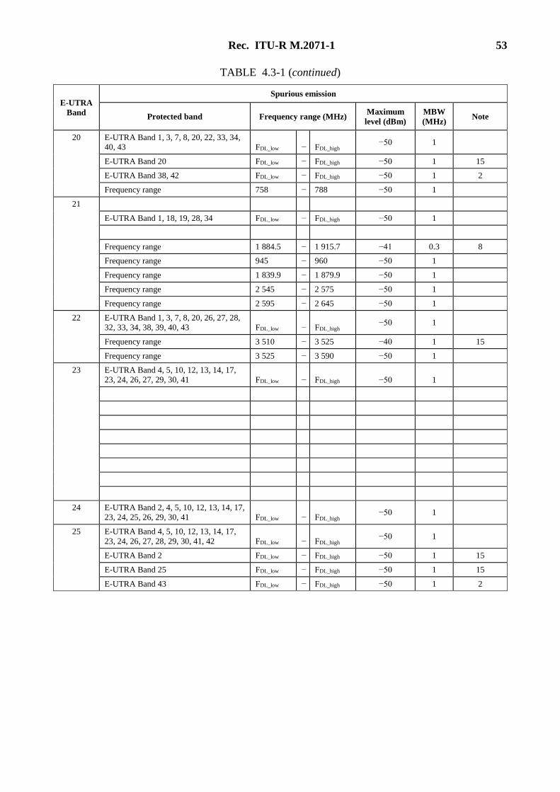
Rec. ITU-R M.2071-1 53
TABLE 4.3-1 (continued)
E-UTRA
Band
Spurious emission
Protected band Frequency range (MHz) Maximum
level (dBm)
MBW
(MHz) Note
20 E-UTRA Band 1, 3, 7, 8, 20, 22, 33, 34, 40, 43 FDL_low − FDL_high
−50 1
E-UTRA Band 20 FDL_low − FDL_high −50 1 15
E-UTRA Band 38, 42 FDL_low − FDL_high −50 1 2
Frequency range 758 − 788 −50 1
21
E-UTRA Band 1, 18, 19, 28, 34 FDL_low − FDL_high −50 1
Frequency range 1 884.5 − 1 915.7 −41 0.3 8
Frequency range 945 − 960 −50 1
Frequency range 1 839.9 − 1 879.9 −50 1
Frequency range 2 545 − 2 575 −50 1
Frequency range 2 595 − 2 645 −50 1
22 E-UTRA Band 1, 3, 7, 8, 20, 26, 27, 28,
32, 33, 34, 38, 39, 40, 43 FDL_low − FDL_high −50 1
Frequency range 3 510 − 3 525 −40 1 15
Frequency range 3 525 − 3 590 −50 1
23 E-UTRA Band 4, 5, 10, 12, 13, 14, 17,
23, 24, 26, 27, 29, 30, 41 FDL_low − FDL_high −50 1
24 E-UTRA Band 2, 4, 5, 10, 12, 13, 14, 17,
23, 24, 25, 26, 29, 30, 41 FDL_low − FDL_high −50 1
25 E-UTRA Band 4, 5, 10, 12, 13, 14, 17,
23, 24, 26, 27, 28, 29, 30, 41, 42 FDL_low − FDL_high −50 1
E-UTRA Band 2 FDL_low − FDL_high −50 1 15
E-UTRA Band 25 FDL_low − FDL_high −50 1 15
E-UTRA Band 43 FDL_low − FDL_high −50 1 2
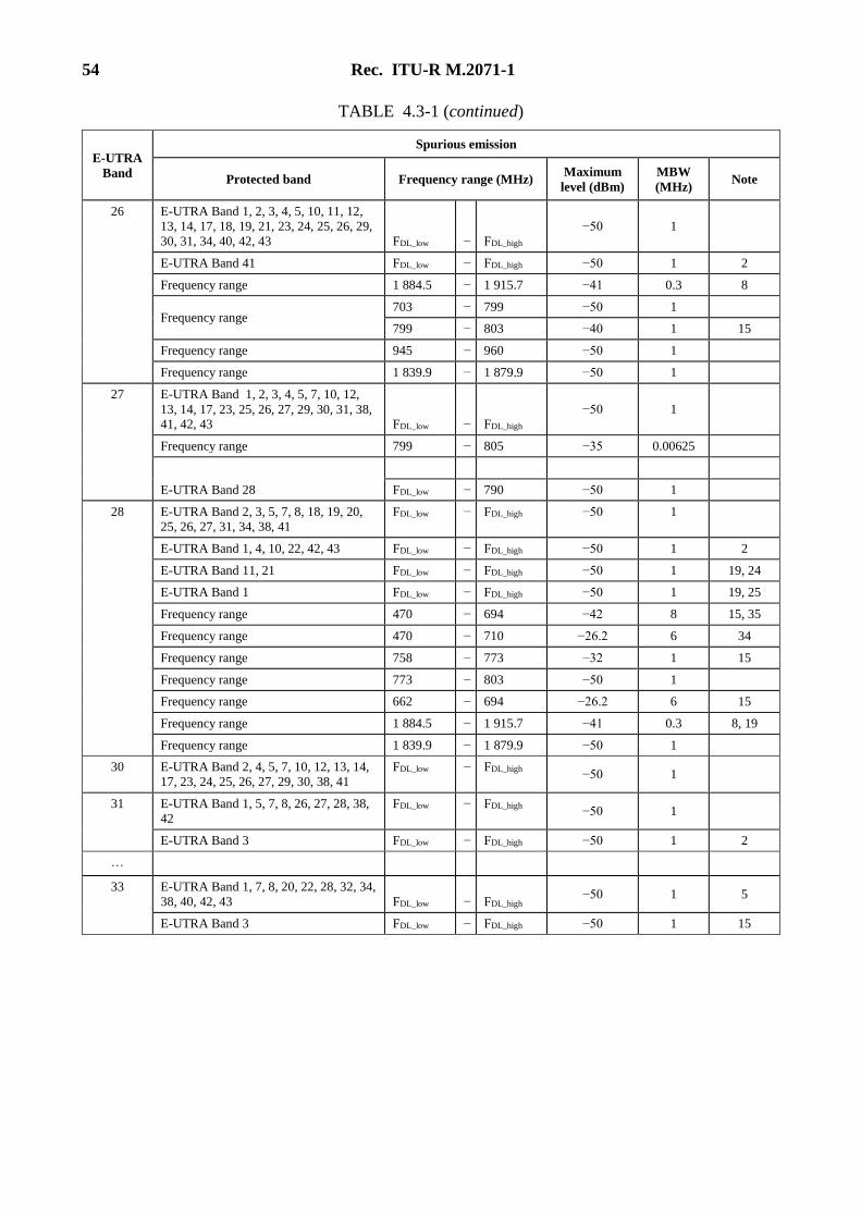
54 Rec. ITU-R M.2071-1
TABLE 4.3-1 (continued)
E-UTRA
Band
Spurious emission
Protected band Frequency range (MHz) Maximum
level (dBm)
MBW
(MHz) Note
26 E-UTRA Band 1, 2, 3, 4, 5, 10, 11, 12,
13, 14, 17, 18, 19, 21, 23, 24, 25, 26, 29,
30, 31, 34, 40, 42, 43 FDL_low − FDL_high
−50 1
E-UTRA Band 41 FDL_low − FDL_high −50 1 2
Frequency range 1 884.5 − 1 915.7 −41 0.3 8
Frequency range 703 − 799 −50 1
799 − 803 −40 1 15
Frequency range 945 − 960 −50 1
Frequency range 1 839.9 − 1 879.9 −50 1
27 E-UTRA Band 1, 2, 3, 4, 5, 7, 10, 12,
13, 14, 17, 23, 25, 26, 27, 29, 30, 31, 38, 41, 42, 43 FDL_low − FDL_high
−50 1
Frequency range 799 − 805 −35 0.00625
E-UTRA Band 28
FDL_low − 790 −50 1
28 E-UTRA Band 2, 3, 5, 7, 8, 18, 19, 20,
25, 26, 27, 31, 34, 38, 41
FDL_low − FDL_high −50 1
E-UTRA Band 1, 4, 10, 22, 42, 43 FDL_low − FDL_high −50 1 2
E-UTRA Band 11, 21 FDL_low − FDL_high −50 1 19, 24
E-UTRA Band 1 FDL_low − FDL_high −50 1 19, 25
Frequency range 470 − 694 −42 8 15, 35
Frequency range 470 − 710 −26.2 6 34
Frequency range 758 − 773 −32 1 15
Frequency range 773 − 803 −50 1
Frequency range 662 − 694 −26.2 6 15
Frequency range 1 884.5 − 1 915.7 −41 0.3 8, 19
Frequency range 1 839.9 − 1 879.9 −50 1
30 E-UTRA Band 2, 4, 5, 7, 10, 12, 13, 14,
17, 23, 24, 25, 26, 27, 29, 30, 38, 41
FDL_low − FDL_high −50 1
31 E-UTRA Band 1, 5, 7, 8, 26, 27, 28, 38,
42
FDL_low − FDL_high −50 1
E-UTRA Band 3 FDL_low − FDL_high −50 1 2
…
33 E-UTRA Band 1, 7, 8, 20, 22, 28, 32, 34,
38, 40, 42, 43 FDL_low − FDL_high −50 1 5
E-UTRA Band 3 FDL_low − FDL_high −50 1 15
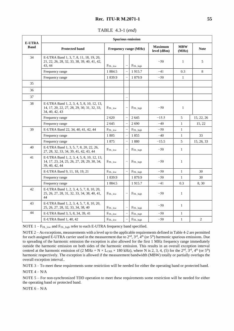
Rec. ITU-R M.2071-1 55
TABLE 4.3-1 (end)
E-UTRA
Band
Spurious emission
Protected band Frequency range (MHz) Maximum
level (dBm)
MBW
(MHz) Note
34 E-UTRA Band 1, 3, 7, 8, 11, 18, 19, 20,
21, 22, 26, 28, 32, 33, 38, 39, 40, 41, 42,
43, 44 FDL_low − FDL_high
−50 1 5
Frequency range 1 884.5 − 1 915.7 −41 0.3 8
Frequency range 1 839.9 − 1 879.9 −50 1
35
36
37 −
38 E-UTRA Band 1, 2, 3, 4, 5, 8, 10, 12, 13,
14, 17, 20, 22, 27, 28, 29, 30, 31, 32, 33, 34, 40, 42, 43
FDL_low − FDL_high −50 1
Frequency range 2 620 − 2 645 −15.5 5 15, 22, 26
Frequency range 2 645 − 2 690 −40 1 15, 22
39 E-UTRA Band 22, 34, 40, 41, 42, 44 FDL_low − FDL_high −50 1
Frequency range 1 805 − 1 855 −40 1 33
Frequency range 1 875 − 1 880 −15.5 5 15, 26, 33
40 E-UTRA Band 1, 3, 5, 7, 8, 20, 22, 26,
27, 28, 32, 33, 34, 39, 41, 42, 43, 44 FDL_low − FDL_high −50 1
41 E-UTRA Band 1, 2, 3, 4, 5, 8, 10, 12, 13,
14, 17, 23, 24, 25, 26, 27, 28, 29, 30, 34,
39, 40, 42, 44
FDL_low − FDL_high −50 1
E-UTRA Band 9, 11, 18, 19, 21 FDL_low − FDL_high −50 1 30
Frequency range 1 839.9 1 879.9 −50 1 30
Frequency range 1 884.5 1 915.7 −41 0.3 8, 30
42 E-UTRA Band 1, 2, 3, 4, 5, 7, 8, 10, 20,
25, 26, 27, 28, 31, 32, 33, 34, 38, 40, 41, 44
FDL_low − FDL_high −50 1
43 E-UTRA Band 1, 2, 3, 4, 5, 7, 8, 10, 20,
25, 26, 27, 28, 32, 33, 34, 38, 40 FDL_low − FDL_high −50 1
44 E-UTRA Band 3, 5, 8, 34, 39, 41 FDL_low − FDL_high −50 1
E-UTRA Band 1, 40, 42 FDL_low − FDL_high −50 1 2
NOTE 1 – FDL_low and FDL_high refer to each E-UTRA frequency band specified.
NOTE 2 – As exceptions, measurements with a level up to the applicable requirements defined in Table 4-2 are permitted
for each assigned E-UTRA carrier used in the measurement due to 2nd, 3rd, 4th (or 5th) harmonic spurious emissions. Due
to spreading of the harmonic emission the exception is also allowed for the first 1 MHz frequency range immediately
outside the harmonic emission on both sides of the harmonic emission. This results in an overall exception interval
centred at the harmonic emission of (2 MHz + N × LCRB × 180 kHz), where N is 2, 3, 4, (5) for the 2nd, 3rd, 4th (or 5th)
harmonic respectively. The exception is allowed if the measurement bandwidth (MBW) totally or partially overlaps the
overall exception interval..
NOTE 3 – To meet these requirements some restriction will be needed for either the operating band or protected band.
NOTE 4 – N/A
NOTE 5 – For non-synchronized TDD operation to meet these requirements some restriction will be needed for either
the operating band or protected band.
NOTE 6 – N/A
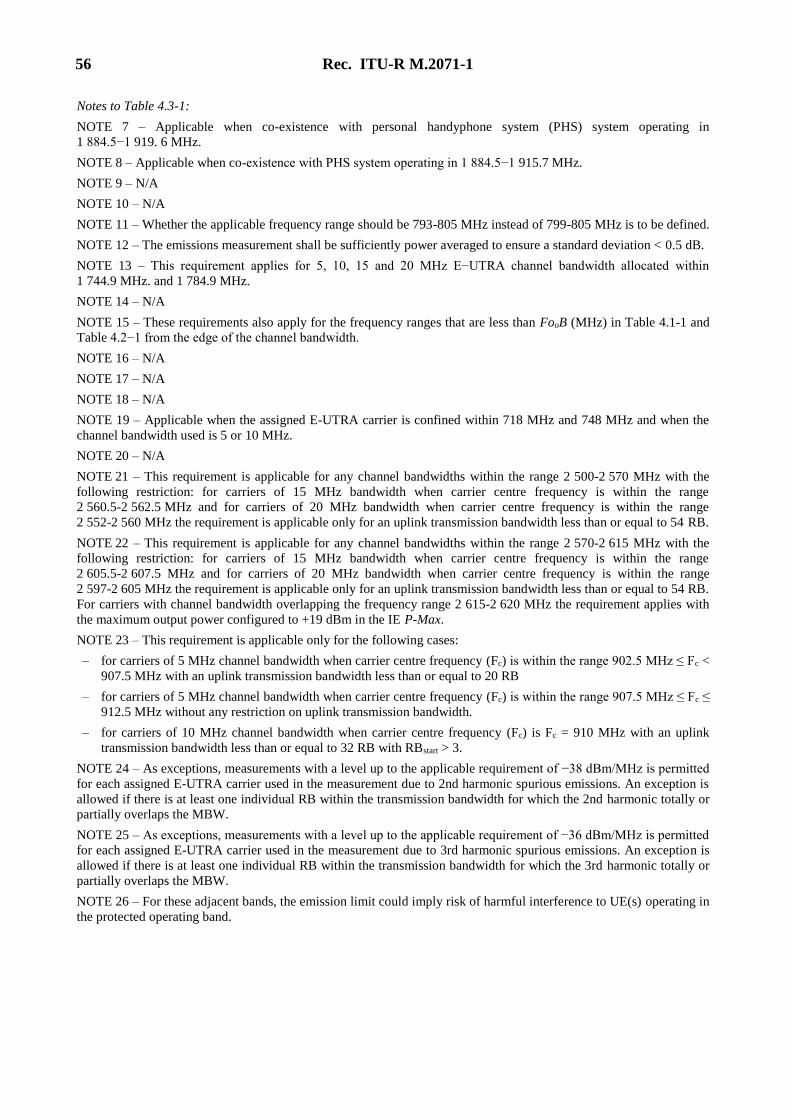
56 Rec. ITU-R M.2071-1
Notes to Table 4.3-1:
NOTE 7 – Applicable when co-existence with personal handyphone system (PHS) system operating in
1 884.5−1 919. 6 MHz.
NOTE 8 – Applicable when co-existence with PHS system operating in 1 884.5−1 915.7 MHz.
NOTE 9 – N/A
NOTE 10 – N/A
NOTE 11 – Whether the applicable frequency range should be 793-805 MHz instead of 799-805 MHz is to be defined.
NOTE 12 – The emissions measurement shall be sufficiently power averaged to ensure a standard deviation < 0.5 dB.
NOTE 13 – This requirement applies for 5, 10, 15 and 20 MHz E−UTRA channel bandwidth allocated within
1 744.9 MHz. and 1 784.9 MHz.
NOTE 14 – N/A
NOTE 15 – These requirements also apply for the frequency ranges that are less than FooB (MHz) in Table 4.1-1 and
Table 4.2−1 from the edge of the channel bandwidth.
NOTE 16 – N/A
NOTE 17 – N/A
NOTE 18 – N/A
NOTE 19 – Applicable when the assigned E-UTRA carrier is confined within 718 MHz and 748 MHz and when the
channel bandwidth used is 5 or 10 MHz.
NOTE 20 – N/A
NOTE 21 – This requirement is applicable for any channel bandwidths within the range 2 500-2 570 MHz with the
following restriction: for carriers of 15 MHz bandwidth when carrier centre frequency is within the range
2 560.5-2 562.5 MHz and for carriers of 20 MHz bandwidth when carrier centre frequency is within the range
2 552-2 560 MHz the requirement is applicable only for an uplink transmission bandwidth less than or equal to 54 RB.
NOTE 22 – This requirement is applicable for any channel bandwidths within the range 2 570-2 615 MHz with the
following restriction: for carriers of 15 MHz bandwidth when carrier centre frequency is within the range
2 605.5-2 607.5 MHz and for carriers of 20 MHz bandwidth when carrier centre frequency is within the range
2 597-2 605 MHz the requirement is applicable only for an uplink transmission bandwidth less than or equal to 54 RB.
For carriers with channel bandwidth overlapping the frequency range 2 615-2 620 MHz the requirement applies with
the maximum output power configured to +19 dBm in the IE P-Max.
NOTE 23 – This requirement is applicable only for the following cases:
– for carriers of 5 MHz channel bandwidth when carrier centre frequency (Fc) is within the range 902.5 MHz ≤ Fc <
907.5 MHz with an uplink transmission bandwidth less than or equal to 20 RB
– for carriers of 5 MHz channel bandwidth when carrier centre frequency (Fc) is within the range 907.5 MHz ≤ Fc ≤
912.5 MHz without any restriction on uplink transmission bandwidth.
– for carriers of 10 MHz channel bandwidth when carrier centre frequency (Fc) is Fc = 910 MHz with an uplink
transmission bandwidth less than or equal to 32 RB with RBstart > 3.
NOTE 24 – As exceptions, measurements with a level up to the applicable requirement of −38 dBm/MHz is permitted
for each assigned E-UTRA carrier used in the measurement due to 2nd harmonic spurious emissions. An exception is
allowed if there is at least one individual RB within the transmission bandwidth for which the 2nd harmonic totally or
partially overlaps the MBW.
NOTE 25 – As exceptions, measurements with a level up to the applicable requirement of −36 dBm/MHz is permitted
for each assigned E-UTRA carrier used in the measurement due to 3rd harmonic spurious emissions. An exception is
allowed if there is at least one individual RB within the transmission bandwidth for which the 3rd harmonic totally or
partially overlaps the MBW.
NOTE 26 – For these adjacent bands, the emission limit could imply risk of harmful interference to UE(s) operating in
the protected operating band.
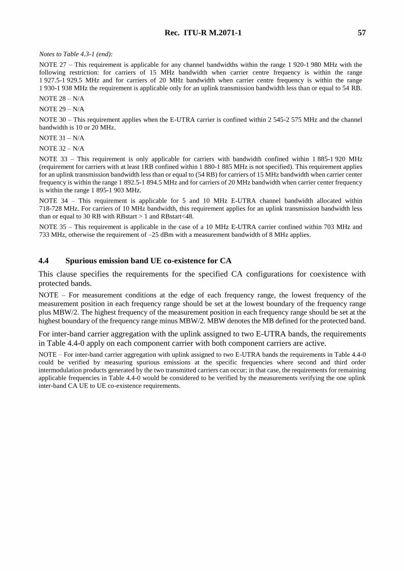
Rec. ITU-R M.2071-1 57
Notes to Table 4.3-1 (end):
NOTE 27 – This requirement is applicable for any channel bandwidths within the range 1 920-1 980 MHz with the
following restriction: for carriers of 15 MHz bandwidth when carrier centre frequency is within the range
1 927.5-1 929.5 MHz and for carriers of 20 MHz bandwidth when carrier centre frequency is within the range
1 930-1 938 MHz the requirement is applicable only for an uplink transmission bandwidth less than or equal to 54 RB.
NOTE 28 – N/A
NOTE 29 – N/A
NOTE 30 – This requirement applies when the E-UTRA carrier is confined within 2 545-2 575 MHz and the channel
bandwidth is 10 or 20 MHz.
NOTE 31 – N/A
NOTE 32 – N/A
NOTE 33 – This requirement is only applicable for carriers with bandwidth confined within 1 885-1 920 MHz
(requirement for carriers with at least 1RB confined within 1 880-1 885 MHz is not specified). This requirement applies
for an uplink transmission bandwidth less than or equal to (54 RB) for carriers of 15 MHz bandwidth when carrier center
frequency is within the range 1 892.5-1 894.5 MHz and for carriers of 20 MHz bandwidth when carrier center frequency
is within the range 1 895-1 903 MHz.
NOTE 34 – This requirement is applicable for 5 and 10 MHz E-UTRA channel bandwidth allocated within
718-728 MHz. For carriers of 10 MHz bandwidth, this requirement applies for an uplink transmission bandwidth less
than or equal to 30 RB with RBstart > 1 and RBstart<48.
NOTE 35 – This requirement is applicable in the case of a 10 MHz E-UTRA carrier confined within 703 MHz and
733 MHz, otherwise the requirement of –25 dBm with a measurement bandwidth of 8 MHz applies.
4.4 Spurious emission band UE co-existence for CA
This clause specifies the requirements for the specified CA configurations for coexistence with
protected bands.
NOTE – For measurement conditions at the edge of each frequency range, the lowest frequency of the
measurement position in each frequency range should be set at the lowest boundary of the frequency range
plus MBW/2. The highest frequency of the measurement position in each frequency range should be set at the
highest boundary of the frequency range minus MBW/2. MBW denotes the MB defined for the protected band.
For inter-band carrier aggregation with the uplink assigned to two E-UTRA bands, the requirements
in Table 4.4-0 apply on each component carrier with both component carriers are active.
NOTE – For inter-band carrier aggregation with uplink assigned to two E-UTRA bands the requirements in Table 4.4-0
could be verified by measuring spurious emissions at the specific frequencies where second and third order
intermodulation products generated by the two transmitted carriers can occur; in that case, the requirements for remaining
applicable frequencies in Table 4.4-0 would be considered to be verified by the measurements verifying the one uplink
inter-band CA UE to UE co-existence requirements.
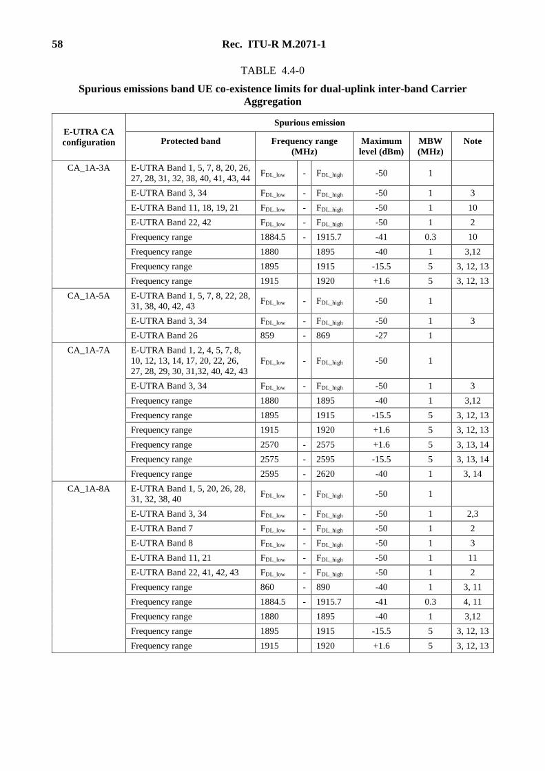
58 Rec. ITU-R M.2071-1
TABLE 4.4-0
Spurious emissions band UE co-existence limits for dual-uplink inter-band Carrier
Aggregation
E-UTRA CA
configuration
Spurious emission
Protected band Frequency range
(MHz)
Maximum
level (dBm)
MBW
(MHz)
Note
CA_1A-3A E-UTRA Band 1, 5, 7, 8, 20, 26,
27, 28, 31, 32, 38, 40, 41, 43, 44 FDL_low - FDL_high -50 1
E-UTRA Band 3, 34 FDL_low - FDL_high -50 1 3
E-UTRA Band 11, 18, 19, 21 FDL_low - FDL_high -50 1 10
E-UTRA Band 22, 42 FDL_low - FDL_high -50 1 2
Frequency range 1884.5 - 1915.7 -41 0.3 10
Frequency range 1880 1895 -40 1 3,12
Frequency range 1895 1915 -15.5 5 3, 12, 13
Frequency range 1915 1920 +1.6 5 3, 12, 13
CA_1A-5A E-UTRA Band 1, 5, 7, 8, 22, 28,
31, 38, 40, 42, 43 FDL_low - FDL_high -50 1
E-UTRA Band 3, 34 FDL_low - FDL_high -50 1 3
E-UTRA Band 26 859 - 869 -27 1
CA_1A-7A E-UTRA Band 1, 2, 4, 5, 7, 8,
10, 12, 13, 14, 17, 20, 22, 26,
27, 28, 29, 30, 31,32, 40, 42, 43
FDL_low - FDL_high -50 1
E-UTRA Band 3, 34 FDL_low - FDL_high -50 1 3
Frequency range 1880 1895 -40 1 3,12
Frequency range 1895 1915 -15.5 5 3, 12, 13
Frequency range 1915 1920 +1.6 5 3, 12, 13
Frequency range 2570 - 2575 +1.6 5 3, 13, 14
Frequency range 2575 - 2595 -15.5 5 3, 13, 14
Frequency range 2595 - 2620 -40 1 3, 14
CA_1A-8A E-UTRA Band 1, 5, 20, 26, 28,
31, 32, 38, 40 FDL_low - FDL_high -50 1
E-UTRA Band 3, 34 FDL_low - FDL_high -50 1 2,3
E-UTRA Band 7 FDL_low - FDL_high -50 1 2
E-UTRA Band 8 FDL_low - FDL_high -50 1 3
E-UTRA Band 11, 21 FDL_low - FDL_high -50 1 11
E-UTRA Band 22, 41, 42, 43 FDL_low - FDL_high -50 1 2
Frequency range 860 - 890 -40 1 3, 11
Frequency range 1884.5 - 1915.7 -41 0.3 4, 11
Frequency range 1880 1895 -40 1 3,12
Frequency range 1895 1915 -15.5 5 3, 12, 13
Frequency range 1915 1920 +1.6 5 3, 12, 13
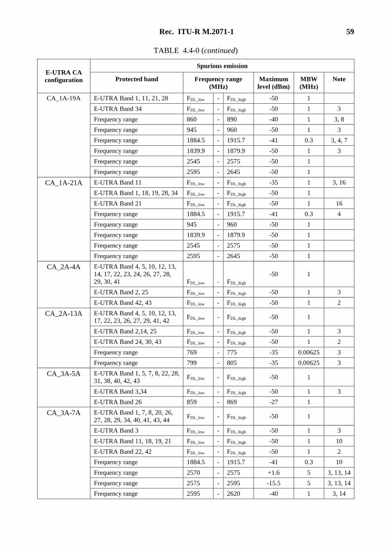
Rec. ITU-R M.2071-1 59
TABLE 4.4-0 (continued)
E-UTRA CA
configuration
Spurious emission
Protected band Frequency range
(MHz)
Maximum
level (dBm)
MBW
(MHz)
Note
CA_1A-19A E-UTRA Band 1, 11, 21, 28 FDL_low - FDL_high -50 1
E-UTRA Band 34 FDL_low - FDL_high -50 1 3
Frequency range 860 - 890 -40 1 3, 8
Frequency range 945 - 960 -50 1 3
Frequency range 1884.5 - 1915.7 -41 0.3 3, 4, 7
Frequency range 1839.9 - 1879.9 -50 1 3
Frequency range 2545 - 2575 -50 1
Frequency range 2595 - 2645 -50 1
CA_1A-21A E-UTRA Band 11 FDL_low - FDL_high -35 1 3, 16
E-UTRA Band 1, 18, 19, 28, 34 FDL_low - FDL_high -50 1
E-UTRA Band 21 FDL_low - FDL_high -50 1 16
Frequency range 1884.5 - 1915.7 -41 0.3 4
Frequency range 945 - 960 -50 1
Frequency range 1839.9 - 1879.9 -50 1
Frequency range 2545 - 2575 -50 1
Frequency range 2595 - 2645 -50 1
CA_2A-4A E-UTRA Band 4, 5, 10, 12, 13,
14, 17, 22, 23, 24, 26, 27, 28,
29, 30, 41 FDL_low - FDL_high
-50 1
E-UTRA Band 2, 25 FDL_low - FDL_high -50 1 3
E-UTRA Band 42, 43 FDL_low - FDL_high -50 1 2
CA_2A-13A E-UTRA Band 4, 5, 10, 12, 13,
17, 22, 23, 26, 27, 29, 41, 42 FDL_low - FDL_high -50 1
E-UTRA Band 2,14, 25 FDL_low - FDL_high -50 1 3
E-UTRA Band 24, 30, 43 FDL_low - FDL_high -50 1 2
Frequency range 769 - 775 -35 0.00625 3
Frequency range 799 - 805 -35 0.00625 3
CA_3A-5A E-UTRA Band 1, 5, 7, 8, 22, 28,
31, 38, 40, 42, 43 FDL_low - FDL_high -50 1
E-UTRA Band 3,34 FDL_low - FDL_high -50 1 3
E-UTRA Band 26 859 - 869 -27 1
CA_3A-7A E-UTRA Band 1, 7, 8, 20, 26,
27, 28, 29, 34, 40, 41, 43, 44 FDL_low - FDL_high -50 1
E-UTRA Band 3 FDL_low - FDL_high -50 1 3
E-UTRA Band 11, 18, 19, 21 FDL_low - FDL_high -50 1 10
E-UTRA Band 22, 42 FDL_low - FDL_high -50 1 2
Frequency range 1884.5 - 1915.7 -41 0.3 10
Frequency range 2570 - 2575 +1.6 5 3, 13, 14
Frequency range 2575 - 2595 -15.5 5 3, 13, 14
Frequency range 2595 - 2620 -40 1 3, 14
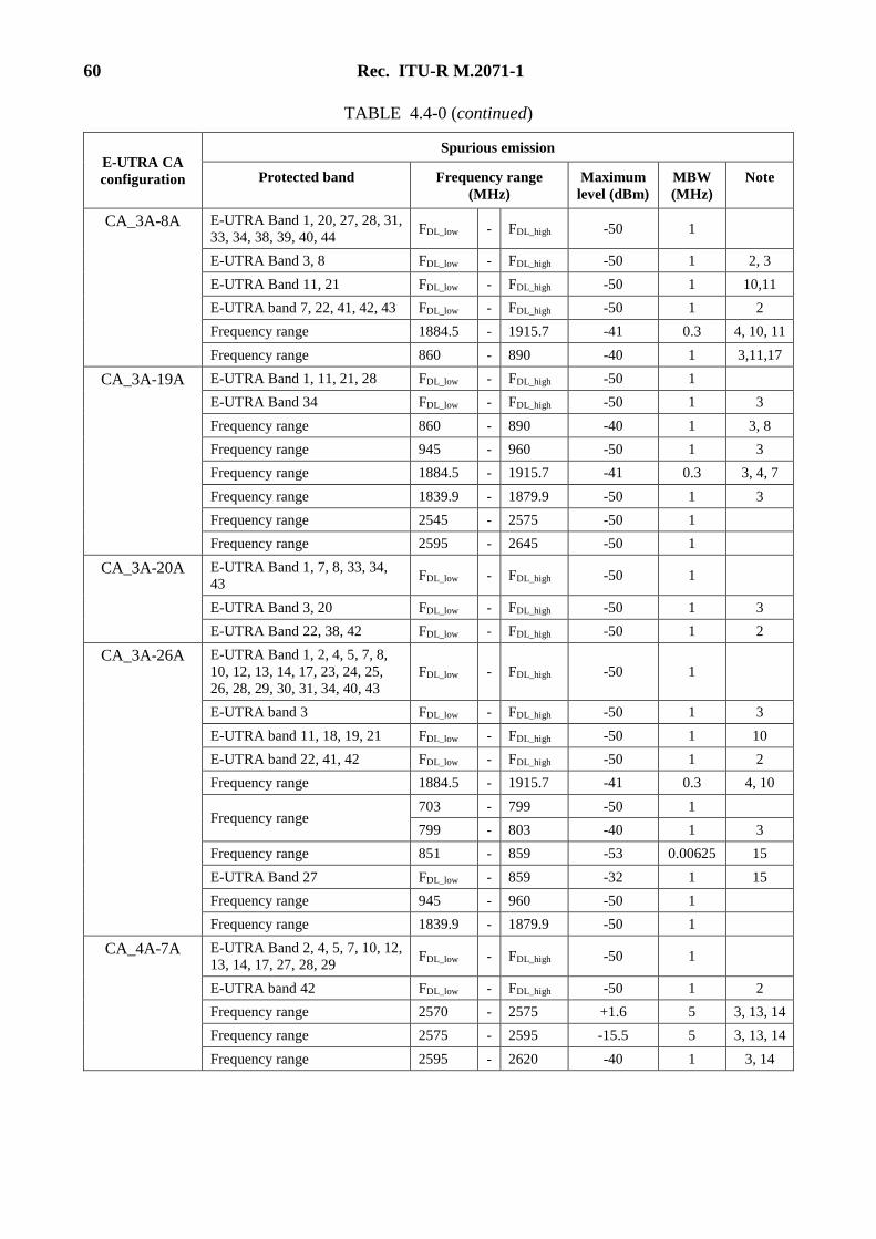
60 Rec. ITU-R M.2071-1
TABLE 4.4-0 (continued)
E-UTRA CA
configuration
Spurious emission
Protected band Frequency range
(MHz)
Maximum
level (dBm)
MBW
(MHz)
Note
CA_3A-8A E-UTRA Band 1, 20, 27, 28, 31,
33, 34, 38, 39, 40, 44 FDL_low - FDL_high -50 1
E-UTRA Band 3, 8 FDL_low - FDL_high -50 1 2, 3
E-UTRA Band 11, 21 FDL_low - FDL_high -50 1 10,11
E-UTRA band 7, 22, 41, 42, 43 FDL_low - FDL_high -50 1 2
Frequency range 1884.5 - 1915.7 -41 0.3 4, 10, 11
Frequency range 860 - 890 -40 1 3,11,17
CA_3A-19A E-UTRA Band 1, 11, 21, 28 FDL_low - FDL_high -50 1
E-UTRA Band 34 FDL_low - FDL_high -50 1 3
Frequency range 860 - 890 -40 1 3, 8
Frequency range 945 - 960 -50 1 3
Frequency range 1884.5 - 1915.7 -41 0.3 3, 4, 7
Frequency range 1839.9 - 1879.9 -50 1 3
Frequency range 2545 - 2575 -50 1
Frequency range 2595 - 2645 -50 1
CA_3A-20A E-UTRA Band 1, 7, 8, 33, 34,
43 FDL_low - FDL_high -50 1
E-UTRA Band 3, 20 FDL_low - FDL_high -50 1 3
E-UTRA Band 22, 38, 42 FDL_low - FDL_high -50 1 2
CA_3A-26A E-UTRA Band 1, 2, 4, 5, 7, 8,
10, 12, 13, 14, 17, 23, 24, 25,
26, 28, 29, 30, 31, 34, 40, 43
FDL_low - FDL_high -50 1
E-UTRA band 3 FDL_low - FDL_high -50 1 3
E-UTRA band 11, 18, 19, 21 FDL_low - FDL_high -50 1 10
E-UTRA band 22, 41, 42 FDL_low - FDL_high -50 1 2
Frequency range 1884.5 - 1915.7 -41 0.3 4, 10
Frequency range 703 - 799 -50 1
799 - 803 -40 1 3
Frequency range 851 - 859 -53 0.00625 15
E-UTRA Band 27 FDL_low - 859 -32 1 15
Frequency range 945 - 960 -50 1
Frequency range 1839.9 - 1879.9 -50 1
CA_4A-7A E-UTRA Band 2, 4, 5, 7, 10, 12,
13, 14, 17, 27, 28, 29 FDL_low - FDL_high -50 1
E-UTRA band 42 FDL_low - FDL_high -50 1 2
Frequency range 2570 - 2575 +1.6 5 3, 13, 14
Frequency range 2575 - 2595 -15.5 5 3, 13, 14
Frequency range 2595 - 2620 -40 1 3, 14
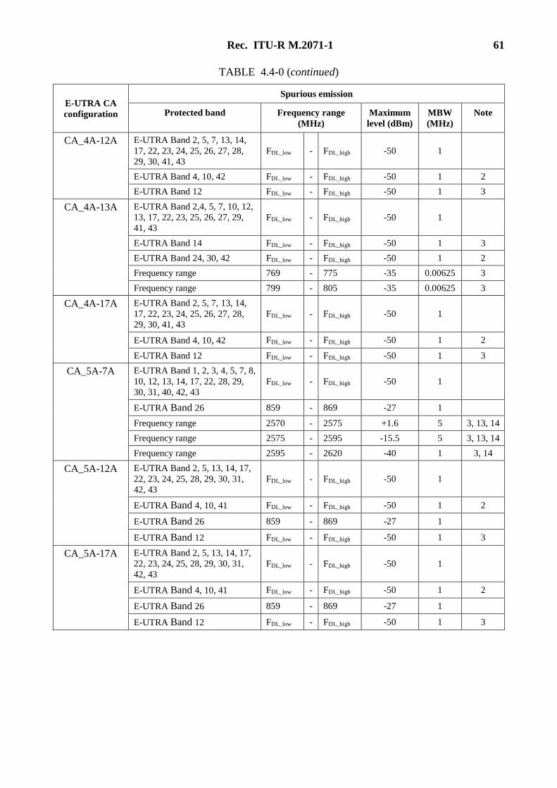
Rec. ITU-R M.2071-1 61
TABLE 4.4-0 (continued)
E-UTRA CA
configuration
Spurious emission
Protected band Frequency range
(MHz)
Maximum
level (dBm)
MBW
(MHz)
Note
CA_4A-12A E-UTRA Band 2, 5, 7, 13, 14,
17, 22, 23, 24, 25, 26, 27, 28,
29, 30, 41, 43
FDL_low - FDL_high -50 1
E-UTRA Band 4, 10, 42 FDL_low - FDL_high -50 1 2
E-UTRA Band 12 FDL_low - FDL_high -50 1 3
CA_4A-13A E-UTRA Band 2,4, 5, 7, 10, 12,
13, 17, 22, 23, 25, 26, 27, 29,
41, 43
FDL_low - FDL_high -50 1
E-UTRA Band 14 FDL_low - FDL_high -50 1 3
E-UTRA Band 24, 30, 42 FDL_low - FDL_high -50 1 2
Frequency range 769 - 775 -35 0.00625 3
Frequency range 799 - 805 -35 0.00625 3
CA_4A-17A E-UTRA Band 2, 5, 7, 13, 14,
17, 22, 23, 24, 25, 26, 27, 28,
29, 30, 41, 43
FDL_low - FDL_high -50 1
E-UTRA Band 4, 10, 42 FDL_low - FDL_high -50 1 2
E-UTRA Band 12 FDL_low - FDL_high -50 1 3
CA_5A-7A E-UTRA Band 1, 2, 3, 4, 5, 7, 8,
10, 12, 13, 14, 17, 22, 28, 29,
30, 31, 40, 42, 43
FDL_low - FDL_high -50 1
E-UTRA Band 26 859 - 869 -27 1
Frequency range 2570 - 2575 +1.6 5 3, 13, 14
Frequency range 2575 - 2595 -15.5 5 3, 13, 14
Frequency range 2595 - 2620 -40 1 3, 14
CA_5A-12A E-UTRA Band 2, 5, 13, 14, 17,
22, 23, 24, 25, 28, 29, 30, 31,
42, 43
FDL_low - FDL_high -50 1
E-UTRA Band 4, 10, 41 FDL_low - FDL_high -50 1 2
E-UTRA Band 26 859 - 869 -27 1
E-UTRA Band 12 FDL_low - FDL_high -50 1 3
CA_5A-17A E-UTRA Band 2, 5, 13, 14, 17,
22, 23, 24, 25, 28, 29, 30, 31,
42, 43
FDL_low - FDL_high -50 1
E-UTRA Band 4, 10, 41 FDL_low - FDL_high -50 1 2
E-UTRA Band 26 859 - 869 -27 1
E-UTRA Band 12 FDL_low - FDL_high -50 1 3
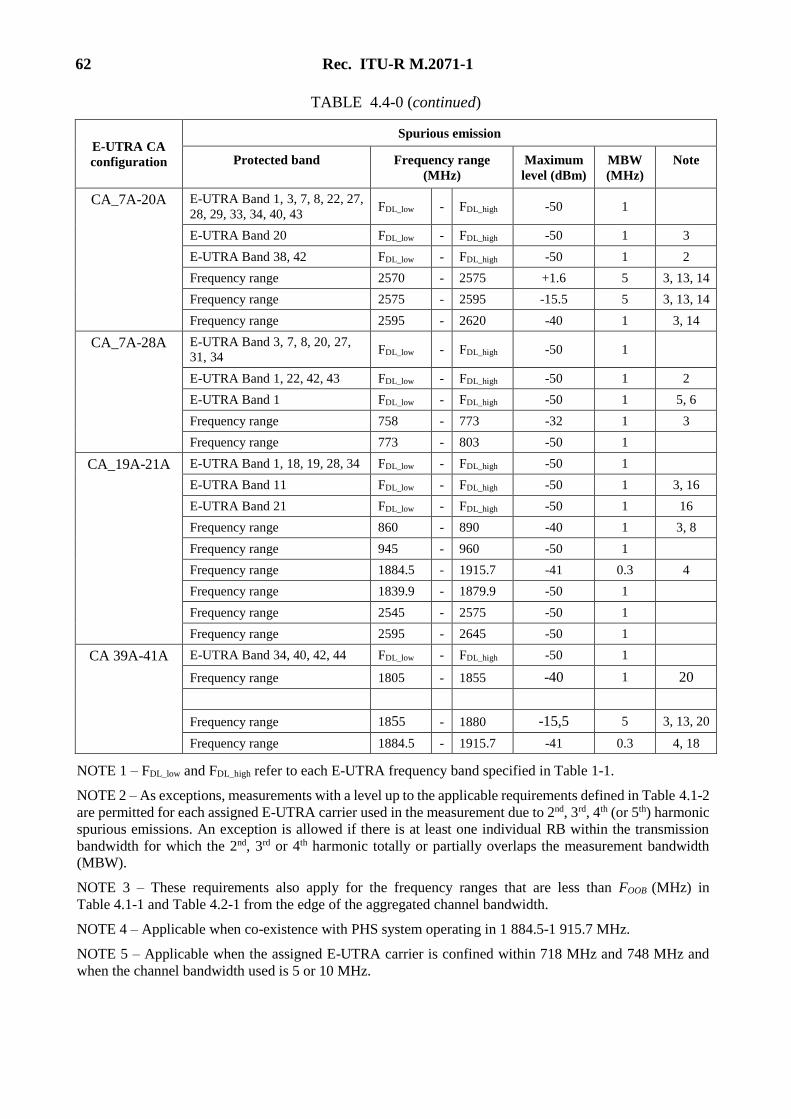
62 Rec. ITU-R M.2071-1
TABLE 4.4-0 (continued)
E-UTRA CA
configuration
Spurious emission
Protected band Frequency range
(MHz)
Maximum
level (dBm)
MBW
(MHz)
Note
CA_7A-20A E-UTRA Band 1, 3, 7, 8, 22, 27,
28, 29, 33, 34, 40, 43 FDL_low - FDL_high -50 1
E-UTRA Band 20 FDL_low - FDL_high -50 1 3
E-UTRA Band 38, 42 FDL_low - FDL_high -50 1 2
Frequency range 2570 - 2575 +1.6 5 3, 13, 14
Frequency range 2575 - 2595 -15.5 5 3, 13, 14
Frequency range 2595 - 2620 -40 1 3, 14
CA_7A-28A E-UTRA Band 3, 7, 8, 20, 27, 31, 34
FDL_low - FDL_high -50 1
E-UTRA Band 1, 22, 42, 43 FDL_low - FDL_high -50 1 2
E-UTRA Band 1 FDL_low - FDL_high -50 1 5, 6
Frequency range 758 - 773 -32 1 3
Frequency range 773 - 803 -50 1
CA_19A-21A E-UTRA Band 1, 18, 19, 28, 34 FDL_low - FDL_high -50 1
E-UTRA Band 11 FDL_low - FDL_high -50 1 3, 16
E-UTRA Band 21 FDL_low - FDL_high -50 1 16
Frequency range 860 - 890 -40 1 3, 8
Frequency range 945 - 960 -50 1
Frequency range 1884.5 - 1915.7 -41 0.3 4
Frequency range 1839.9 - 1879.9 -50 1
Frequency range 2545 - 2575 -50 1
Frequency range 2595 - 2645 -50 1
CA 39A-41A E-UTRA Band 34, 40, 42, 44 FDL_low - FDL_high -50 1
Frequency range 1805 - 1855 -40 1 20
Frequency range 1855 - 1880 -15,5 5 3, 13, 20
Frequency range 1884.5 - 1915.7 -41 0.3 4, 18
NOTE 1 – FDL_low and FDL_high refer to each E-UTRA frequency band specified in Table 1-1.
NOTE 2 – As exceptions, measurements with a level up to the applicable requirements defined in Table 4.1-2
are permitted for each assigned E-UTRA carrier used in the measurement due to 2nd, 3rd, 4th (or 5th) harmonic
spurious emissions. An exception is allowed if there is at least one individual RB within the transmission
bandwidth for which the 2nd, 3rd or 4th harmonic totally or partially overlaps the measurement bandwidth
(MBW).
NOTE 3 – These requirements also apply for the frequency ranges that are less than FOOB (MHz) in
Table 4.1-1 and Table 4.2-1 from the edge of the aggregated channel bandwidth.
NOTE 4 – Applicable when co-existence with PHS system operating in 1 884.5-1 915.7 MHz.
NOTE 5 – Applicable when the assigned E-UTRA carrier is confined within 718 MHz and 748 MHz and
when the channel bandwidth used is 5 or 10 MHz.
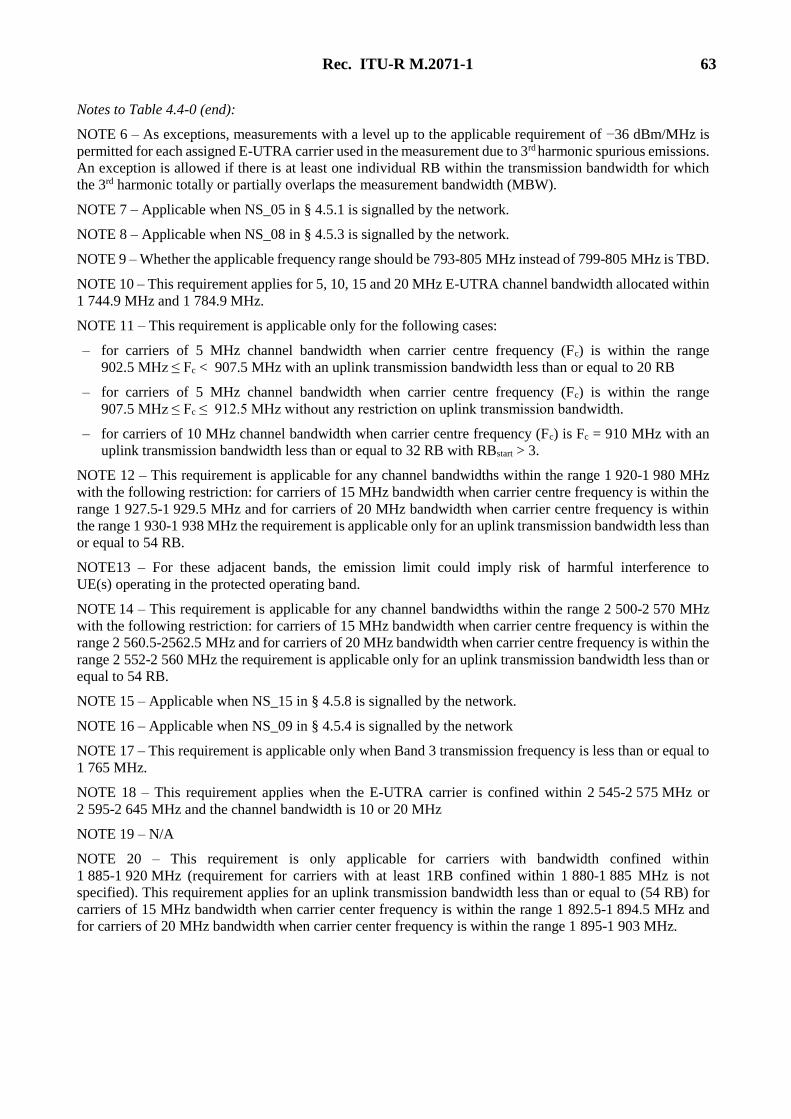
Rec. ITU-R M.2071-1 63
Notes to Table 4.4-0 (end):
NOTE 6 – As exceptions, measurements with a level up to the applicable requirement of −36 dBm/MHz is
permitted for each assigned E-UTRA carrier used in the measurement due to 3rd harmonic spurious emissions.
An exception is allowed if there is at least one individual RB within the transmission bandwidth for which
the 3rd harmonic totally or partially overlaps the measurement bandwidth (MBW).
NOTE 7 – Applicable when NS_05 in § 4.5.1 is signalled by the network.
NOTE 8 – Applicable when NS_08 in § 4.5.3 is signalled by the network.
NOTE 9 – Whether the applicable frequency range should be 793-805 MHz instead of 799-805 MHz is TBD.
NOTE 10 – This requirement applies for 5, 10, 15 and 20 MHz E-UTRA channel bandwidth allocated within
1 744.9 MHz and 1 784.9 MHz.
NOTE 11 – This requirement is applicable only for the following cases:
– for carriers of 5 MHz channel bandwidth when carrier centre frequency (Fc) is within the range
902.5 MHz ≤ Fc < 907.5 MHz with an uplink transmission bandwidth less than or equal to 20 RB
– for carriers of 5 MHz channel bandwidth when carrier centre frequency (Fc) is within the range
907.5 MHz ≤ Fc ≤ 912.5 MHz without any restriction on uplink transmission bandwidth.
– for carriers of 10 MHz channel bandwidth when carrier centre frequency (Fc) is Fc = 910 MHz with an
uplink transmission bandwidth less than or equal to 32 RB with RBstart > 3.
NOTE 12 – This requirement is applicable for any channel bandwidths within the range 1 920-1 980 MHz
with the following restriction: for carriers of 15 MHz bandwidth when carrier centre frequency is within the
range 1 927.5-1 929.5 MHz and for carriers of 20 MHz bandwidth when carrier centre frequency is within
the range 1 930-1 938 MHz the requirement is applicable only for an uplink transmission bandwidth less than
or equal to 54 RB.
NOTE13 – For these adjacent bands, the emission limit could imply risk of harmful interference to
UE(s) operating in the protected operating band.
NOTE 14 – This requirement is applicable for any channel bandwidths within the range 2 500-2 570 MHz
with the following restriction: for carriers of 15 MHz bandwidth when carrier centre frequency is within the
range 2 560.5-2562.5 MHz and for carriers of 20 MHz bandwidth when carrier centre frequency is within the
range 2 552-2 560 MHz the requirement is applicable only for an uplink transmission bandwidth less than or
equal to 54 RB.
NOTE 15 – Applicable when NS_15 in § 4.5.8 is signalled by the network.
NOTE 16 – Applicable when NS_09 in § 4.5.4 is signalled by the network
NOTE 17 – This requirement is applicable only when Band 3 transmission frequency is less than or equal to
1 765 MHz.
NOTE 18 – This requirement applies when the E-UTRA carrier is confined within 2 545-2 575 MHz or
2 595-2 645 MHz and the channel bandwidth is 10 or 20 MHz
NOTE 19 – N/A
NOTE 20 – This requirement is only applicable for carriers with bandwidth confined within
1 885-1 920 MHz (requirement for carriers with at least 1RB confined within 1 880-1 885 MHz is not
specified). This requirement applies for an uplink transmission bandwidth less than or equal to (54 RB) for
carriers of 15 MHz bandwidth when carrier center frequency is within the range 1 892.5-1 894.5 MHz and
for carriers of 20 MHz bandwidth when carrier center frequency is within the range 1 895-1 903 MHz.

64 Rec. ITU-R M.2071-1
TABLE 4.4-1
Spurious emissions band UE co-existence limits for intra band Carrier Aggregation
E-UTRA
CA
Configu-
ration
Spurious emission
Protected band Frequency range (MHz) Maximum
level (dBm)
MBW
(MHz) Note
CA_1C E-UTRA Band 1, 3, 7, 8, 9, 11,
18, 19, 20, 21, 22, 26, 27, 28,
31, 38, 40, 41, 42, 43, 44 FDL_low − FDL_high
−50 1
E-UTRA Band 34 FDL_low − FDL_high −50 1 4, 6, 7
Frequency range 1 900 1 915 −15.5 5
6, 7, 10,
12
Frequency range 1 915 1 920 +1.6 5
6, 7, 10,
12
Frequency range 1 880 1 895 −40 1 7, 10
Frequency range 1 895 1 915 −15.5 5
6, 7, 10,
12
Frequency range 1 884.5 − 1 915.7 −41 0.3 4, 5
Frequency range 1 839.9 − 1 879.9 −50 1
CA_3C E-UTRA Band 1, 7, 8, 20, 26,
27, 28, 31, 33, 34, 38, 41, 43,
44 FDL_low − FDL_high
−50 1
E-UTRA Band 3 FDL_low − FDL_high −50 1 10
E-UTRA Band 22, 42 FDL_low − FDL_high −50 1 2
CA_7C E-UTRA Band 1, 3, 7, 8, 20,
22, 27, 28, 29, 30, 31, 33, 34,
40, 42, 43 FDL_low − FDL_high
−50 1
Frequency range 2 570 − 2 575 +1.6 5 8, 12
Frequency range 2 575 − 2 595 −15.5 5 8, 12
Frequency range 2 595 − 2 620 −40 1 8
CA_38C E-UTRA Band 1, 3, 8, 20, 22,
27, 28, 29, 30, 31, 33, 34, 40,
42, 43 FDL_low − FDL_high
−50 1
Frequency range 2 620 − 2 645 −15.5 5
9, 10, 11,
12
Frequency range 2 645 − 2 690 −40 1 9, 10,11
CA_39C E-UTRA Band 22, 34, 40, 41,
42, 44 FDL_low − FDL_high −50 1
CA_40C E-UTRA Band 1, 3, 7, 8, 20,
22, 26, 27, 33, 34, 38, 39, 41,
42, 43, 44 FDL_low − FDL_high
−50 1
CA_41C E-UTRA Band 1, 2, 3, 4, 5, 8,
10, 12, 13, 14, 17, 23, 24, 25,
26, 27, 28, 29, 30, 34, 39, 40,
42, 44 FDL_low − FDL_high
−50 1
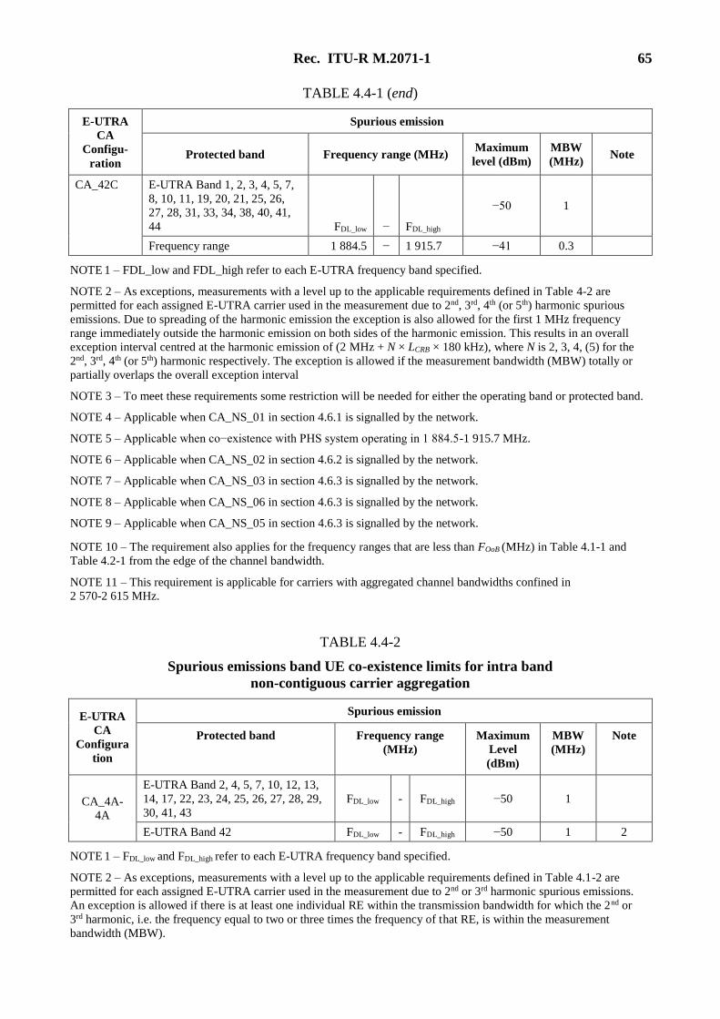
Rec. ITU-R M.2071-1 65
TABLE 4.4-1 (end)
E-UTRA
CA
Configu-
ration
Spurious emission
Protected band Frequency range (MHz) Maximum
level (dBm)
MBW
(MHz) Note
CA_42C E-UTRA Band 1, 2, 3, 4, 5, 7,
8, 10, 11, 19, 20, 21, 25, 26,
27, 28, 31, 33, 34, 38, 40, 41,
44 FDL_low − FDL_high
−50 1
Frequency range 1 884.5 − 1 915.7 −41 0.3
NOTE 1 – FDL_low and FDL_high refer to each E-UTRA frequency band specified.
NOTE 2 – As exceptions, measurements with a level up to the applicable requirements defined in Table 4-2 are
permitted for each assigned E-UTRA carrier used in the measurement due to 2nd, 3rd, 4th (or 5th) harmonic spurious
emissions. Due to spreading of the harmonic emission the exception is also allowed for the first 1 MHz frequency
range immediately outside the harmonic emission on both sides of the harmonic emission. This results in an overall
exception interval centred at the harmonic emission of (2 MHz + N × LCRB × 180 kHz), where N is 2, 3, 4, (5) for the
2nd, 3rd, 4th (or 5th) harmonic respectively. The exception is allowed if the measurement bandwidth (MBW) totally or
partially overlaps the overall exception interval
NOTE 3 – To meet these requirements some restriction will be needed for either the operating band or protected band.
NOTE 4 – Applicable when CA_NS_01 in section 4.6.1 is signalled by the network.
NOTE 5 – Applicable when co−existence with PHS system operating in 1 884.5-1 915.7 MHz.
NOTE 6 – Applicable when CA_NS_02 in section 4.6.2 is signalled by the network.
NOTE 7 – Applicable when CA_NS_03 in section 4.6.3 is signalled by the network.
NOTE 8 – Applicable when CA_NS_06 in section 4.6.3 is signalled by the network.
NOTE 9 – Applicable when CA_NS_05 in section 4.6.3 is signalled by the network.
NOTE 10 – The requirement also applies for the frequency ranges that are less than FOoB (MHz) in Table 4.1-1 and
Table 4.2-1 from the edge of the channel bandwidth.
NOTE 11 – This requirement is applicable for carriers with aggregated channel bandwidths confined in
2 570-2 615 MHz.
TABLE 4.4-2
Spurious emissions band UE co-existence limits for intra band
non-contiguous carrier aggregation
E-UTRA
CA
Configura
tion
Spurious emission
Protected band Frequency range
(MHz)
Maximum
Level
(dBm)
MBW
(MHz)
Note
CA_4A-
4A
E-UTRA Band 2, 4, 5, 7, 10, 12, 13,
14, 17, 22, 23, 24, 25, 26, 27, 28, 29,
30, 41, 43
FDL_low - FDL_high −50 1
E-UTRA Band 42 FDL_low - FDL_high −50 1 2
NOTE 1 – FDL_low and FDL_high refer to each E-UTRA frequency band specified.
NOTE 2 – As exceptions, measurements with a level up to the applicable requirements defined in Table 4.1-2 are
permitted for each assigned E-UTRA carrier used in the measurement due to 2nd or 3rd harmonic spurious emissions.
An exception is allowed if there is at least one individual RE within the transmission bandwidth for which the 2nd or
3rd harmonic, i.e. the frequency equal to two or three times the frequency of that RE, is within the measurement
bandwidth (MBW).
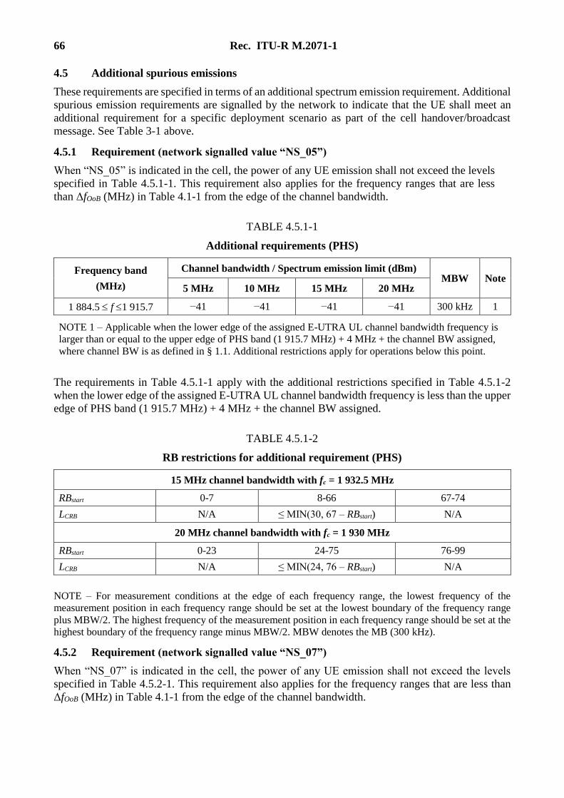
66 Rec. ITU-R M.2071-1
4.5 Additional spurious emissions
These requirements are specified in terms of an additional spectrum emission requirement. Additional
spurious emission requirements are signalled by the network to indicate that the UE shall meet an
additional requirement for a specific deployment scenario as part of the cell handover/broadcast
message. See Table 3-1 above.
4.5.1 Requirement (network signalled value “NS_05”)
When “NS_05” is indicated in the cell, the power of any UE emission shall not exceed the levels
specified in Table 4.5.1-1. This requirement also applies for the frequency ranges that are less
than ΔfOoB (MHz) in Table 4.1-1 from the edge of the channel bandwidth.
TABLE 4.5.1-1
Additional requirements (PHS)
Frequency band
(MHz)
Channel bandwidth / Spectrum emission limit (dBm) MBW Note
5 MHz 10 MHz 15 MHz 20 MHz
1 884.5 f 1 915.7 −41 −41 −41 −41 300 kHz 1
NOTE 1 – Applicable when the lower edge of the assigned E-UTRA UL channel bandwidth frequency is
larger than or equal to the upper edge of PHS band (1 915.7 MHz) + 4 MHz + the channel BW assigned,
where channel BW is as defined in § 1.1. Additional restrictions apply for operations below this point.
The requirements in Table 4.5.1-1 apply with the additional restrictions specified in Table 4.5.1-2
when the lower edge of the assigned E-UTRA UL channel bandwidth frequency is less than the upper
edge of PHS band (1 915.7 MHz) + 4 MHz + the channel BW assigned.
TABLE 4.5.1-2
RB restrictions for additional requirement (PHS)
15 MHz channel bandwidth with fc = 1 932.5 MHz
RBstart 0-7 8-66 67-74
LCRB N/A ≤ MIN(30, 67 – RBstart) N/A
20 MHz channel bandwidth with fc = 1 930 MHz
RBstart 0-23 24-75 76-99
LCRB N/A ≤ MIN(24, 76 – RBstart) N/A
NOTE – For measurement conditions at the edge of each frequency range, the lowest frequency of the
measurement position in each frequency range should be set at the lowest boundary of the frequency range
plus MBW/2. The highest frequency of the measurement position in each frequency range should be set at the
highest boundary of the frequency range minus MBW/2. MBW denotes the MB (300 kHz).
4.5.2 Requirement (network signalled value “NS_07”)
When “NS_07” is indicated in the cell, the power of any UE emission shall not exceed the levels
specified in Table 4.5.2-1. This requirement also applies for the frequency ranges that are less than
ΔfOoB (MHz) in Table 4.1-1 from the edge of the channel bandwidth.
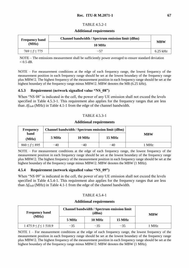
Rec. ITU-R M.2071-1 67
TABLE 4.5.2-1
Additional requirements
Frequency band
(MHz)
Channel bandwidth / Spectrum emission limit (dBm) MBW
10 MHz
769 ≤ f ≤ 775 −57 6.25 kHz
NOTE – The emissions measurement shall be sufficiently power averaged to ensure standard deviation
< 0.5 dB.
NOTE – For measurement conditions at the edge of each frequency range, the lowest frequency of the
measurement position in each frequency range should be set at the lowest boundary of the frequency range
plus MBW/2. The highest frequency of the measurement position in each frequency range should be set at the
highest boundary of the frequency range minus MBW/2. MBW denotes the MB (6.25 kHz).
4.5.3 Requirement (network signalled value “NS_08”)
When “NS 08” is indicated in the cell, the power of any UE emission shall not exceed the levels
specified in Table 4.5.3-1. This requirement also applies for the frequency ranges that are less
than ΔfOoB (MHz) in Table 4.1-1 from the edge of the channel bandwidth.
TABLE 4.5.3-1
Additional requirements
Frequency
band
(MHz)
Channel bandwidth / Spectrum emission limit (dBm)
MBW 5 MHz 10 MHz 15 MHz
860 ≤ f ≤ 895 −40 −40 −40 1 MHz
NOTE – For measurement conditions at the edge of each frequency range, the lowest frequency of the
measurement position in each frequency range should be set at the lowest boundary of the frequency range
plus MBW/2. The highest frequency of the measurement position in each frequency range should be set at the
highest boundary of the frequency range minus MBW/2. MBW denotes the MBW (1 MHz).
4.5.4 Requirement (network signalled value “NS_09”)
When “NS 09” is indicated in the cell, the power of any UE emission shall not exceed the levels
specified in Table 4.5.4-1. This requirement also applies for the frequency ranges that are less
than ΔfOoB (MHz) in Table 4.1-1 from the edge of the channel bandwidth.
TABLE 4.5.4-1
Additional requirements
Frequency band
(MHz)
Channel bandwidth / Spectrum emission limit
(dBm) MBW
5 MHz 10 MHz 15 MHz
1 475.9 ≤ f ≤ 1 510.9 −35 −35 −35 1 MHz
NOTE 1 – For measurement conditions at the edge of each frequency range, the lowest frequency of the
measurement position in each frequency range should be set at the lowest boundary of the frequency range
plus MBW/2. The highest frequency of the measurement position in each frequency range should be set at the
highest boundary of the frequency range minus MBW/2. MBW denotes the MBW (1 MHz).
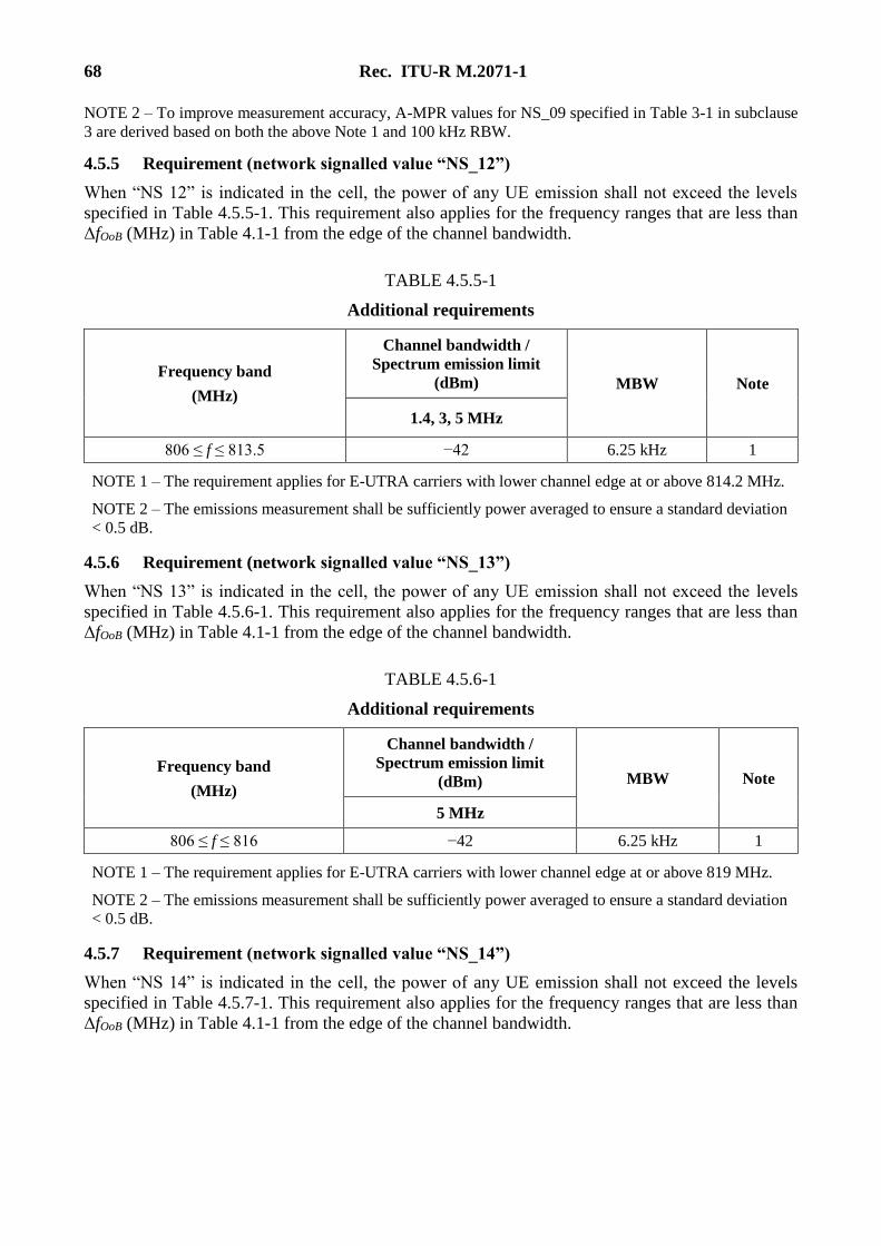
68 Rec. ITU-R M.2071-1
NOTE 2 – To improve measurement accuracy, A-MPR values for NS_09 specified in Table 3-1 in subclause
3 are derived based on both the above Note 1 and 100 kHz RBW.
4.5.5 Requirement (network signalled value “NS_12”)
When “NS 12” is indicated in the cell, the power of any UE emission shall not exceed the levels
specified in Table 4.5.5-1. This requirement also applies for the frequency ranges that are less than
ΔfOoB (MHz) in Table 4.1-1 from the edge of the channel bandwidth.
TABLE 4.5.5-1
Additional requirements
Frequency band
(MHz)
Channel bandwidth /
Spectrum emission limit
(dBm) MBW Note
1.4, 3, 5 MHz
806 ≤ f ≤ 813.5 −42 6.25 kHz 1
NOTE 1 – The requirement applies for E-UTRA carriers with lower channel edge at or above 814.2 MHz.
NOTE 2 – The emissions measurement shall be sufficiently power averaged to ensure a standard deviation
< 0.5 dB.
4.5.6 Requirement (network signalled value “NS_13”)
When “NS 13” is indicated in the cell, the power of any UE emission shall not exceed the levels
specified in Table 4.5.6-1. This requirement also applies for the frequency ranges that are less than
ΔfOoB (MHz) in Table 4.1-1 from the edge of the channel bandwidth.
TABLE 4.5.6-1
Additional requirements
Frequency band
(MHz)
Channel bandwidth /
Spectrum emission limit
(dBm) MBW Note
5 MHz
806 ≤ f ≤ 816 −42 6.25 kHz 1
NOTE 1 – The requirement applies for E-UTRA carriers with lower channel edge at or above 819 MHz.
NOTE 2 – The emissions measurement shall be sufficiently power averaged to ensure a standard deviation
< 0.5 dB.
4.5.7 Requirement (network signalled value “NS_14”)
When “NS 14” is indicated in the cell, the power of any UE emission shall not exceed the levels
specified in Table 4.5.7-1. This requirement also applies for the frequency ranges that are less than
ΔfOoB (MHz) in Table 4.1-1 from the edge of the channel bandwidth.
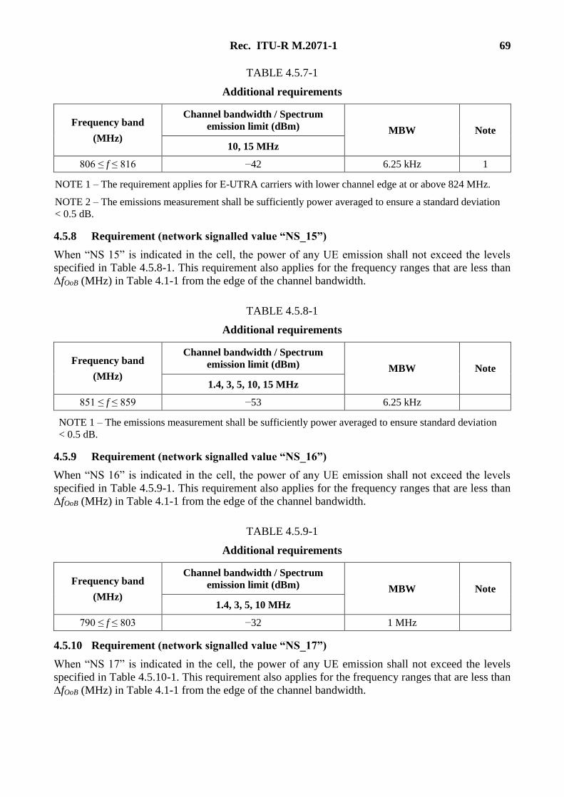
Rec. ITU-R M.2071-1 69
TABLE 4.5.7-1
Additional requirements
Frequency band
(MHz)
Channel bandwidth / Spectrum
emission limit (dBm) MBW Note
10, 15 MHz
806 ≤ f ≤ 816 −42 6.25 kHz 1
NOTE 1 – The requirement applies for E-UTRA carriers with lower channel edge at or above 824 MHz.
NOTE 2 – The emissions measurement shall be sufficiently power averaged to ensure a standard deviation
< 0.5 dB.
4.5.8 Requirement (network signalled value “NS_15”)
When “NS 15” is indicated in the cell, the power of any UE emission shall not exceed the levels
specified in Table 4.5.8-1. This requirement also applies for the frequency ranges that are less than
ΔfOoB (MHz) in Table 4.1-1 from the edge of the channel bandwidth.
TABLE 4.5.8-1
Additional requirements
Frequency band
(MHz)
Channel bandwidth / Spectrum
emission limit (dBm) MBW Note
1.4, 3, 5, 10, 15 MHz
851 ≤ f ≤ 859 −53 6.25 kHz
NOTE 1 – The emissions measurement shall be sufficiently power averaged to ensure standard deviation
< 0.5 dB.
4.5.9 Requirement (network signalled value “NS_16”)
When “NS 16” is indicated in the cell, the power of any UE emission shall not exceed the levels
specified in Table 4.5.9-1. This requirement also applies for the frequency ranges that are less than
ΔfOoB (MHz) in Table 4.1-1 from the edge of the channel bandwidth.
TABLE 4.5.9-1
Additional requirements
Frequency band
(MHz)
Channel bandwidth / Spectrum
emission limit (dBm) MBW Note
1.4, 3, 5, 10 MHz
790 ≤ f ≤ 803 −32 1 MHz
4.5.10 Requirement (network signalled value “NS_17”)
When “NS 17” is indicated in the cell, the power of any UE emission shall not exceed the levels
specified in Table 4.5.10-1. This requirement also applies for the frequency ranges that are less than
ΔfOoB (MHz) in Table 4.1-1 from the edge of the channel bandwidth.
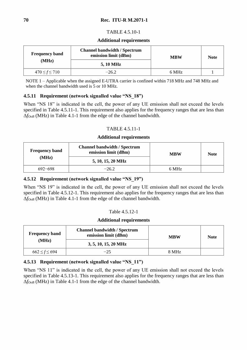
70 Rec. ITU-R M.2071-1
TABLE 4.5.10-1
Additional requirements
Frequency band
(MHz)
Channel bandwidth / Spectrum
emission limit (dBm) MBW Note
5, 10 MHz
470 ≤ f ≤ 710 −26.2 6 MHz 1
NOTE 1 – Applicable when the assigned E-UTRA carrier is confined within 718 MHz and 748 MHz and
when the channel bandwidth used is 5 or 10 MHz.
4.5.11 Requirement (network signalled value “NS_18”)
When “NS 18” is indicated in the cell, the power of any UE emission shall not exceed the levels
specified in Table 4.5.11-1. This requirement also applies for the frequency ranges that are less than
ΔfOoB (MHz) in Table 4.1-1 from the edge of the channel bandwidth.
TABLE 4.5.11-1
Additional requirements
Frequency band
(MHz)
Channel bandwidth / Spectrum
emission limit (dBm) MBW Note
5, 10, 15, 20 MHz
692−698 −26.2 6 MHz
4.5.12 Requirement (network signalled value “NS_19”)
When “NS 19” is indicated in the cell, the power of any UE emission shall not exceed the levels
specified in Table 4.5.12-1. This requirement also applies for the frequency ranges that are less than
ΔfOoB (MHz) in Table 4.1-1 from the edge of the channel bandwidth.
Table 4.5.12-1
Additional requirements
Frequency band
(MHz)
Channel bandwidth / Spectrum
emission limit (dBm) MBW Note
3, 5, 10, 15, 20 MHz
662 ≤ f ≤ 694 −25 8 MHz
4.5.13 Requirement (network signalled value “NS_11”)
When “NS 11” is indicated in the cell, the power of any UE emission shall not exceed the levels
specified in Table 4.5.13-1. This requirement also applies for the frequency ranges that are less than
ΔfOoB (MHz) in Table 4.1-1 from the edge of the channel bandwidth.
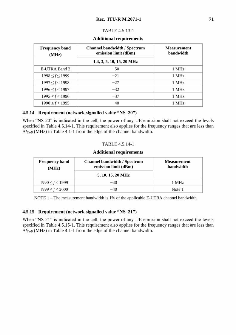
Rec. ITU-R M.2071-1 71
TABLE 4.5.13-1
Additional requirements
Frequency band
(MHz)
Channel bandwidth / Spectrum
emission limit (dBm)
Measurement
bandwidth
1.4, 3, 5, 10, 15, 20 MHz
E-UTRA Band 2 −50 1 MHz
1998 ≤ f ≤ 1999 −21 1 MHz
1997 ≤ f < 1998 −27 1 MHz
1996 ≤ f < 1997 −32 1 MHz
1995 ≤ f < 1996 −37 1 MHz
1990 ≤ f < 1995 −40 1 MHz
4.5.14 Requirement (network signalled value “NS_20”)
When “NS 20” is indicated in the cell, the power of any UE emission shall not exceed the levels
specified in Table 4.5.14-1. This requirement also applies for the frequency ranges that are less than
ΔfOoB (MHz) in Table 4.1-1 from the edge of the channel bandwidth.
TABLE 4.5.14-1
Additional requirements
Frequency band
(MHz)
Channel bandwidth / Spectrum
emission limit (dBm)
Measurement
bandwidth
5, 10, 15, 20 MHz
1990 ≤ f < 1999 −40 1 MHz
1999 ≤ f ≤ 2000 −40 Note 1
NOTE 1 – The measurement bandwidth is 1% of the applicable E-UTRA channel bandwidth.
4.5.15 Requirement (network signalled value “NS_21”)
When “NS 21” is indicated in the cell, the power of any UE emission shall not exceed the levels
specified in Table 4.5.15-1. This requirement also applies for the frequency ranges that are less than
ΔfOoB (MHz) in Table 4.1-1 from the edge of the channel bandwidth.
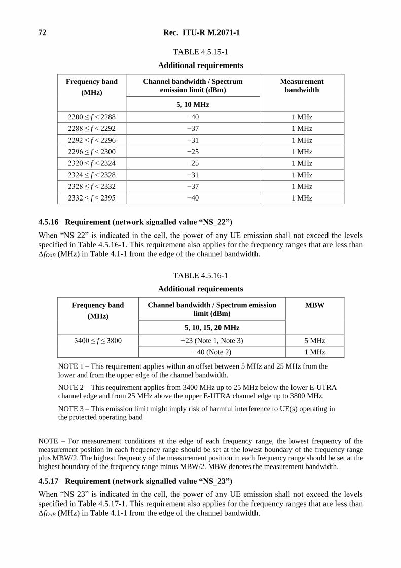
72 Rec. ITU-R M.2071-1
TABLE 4.5.15-1
Additional requirements
Frequency band
(MHz)
Channel bandwidth / Spectrum
emission limit (dBm)
Measurement
bandwidth
5, 10 MHz
2200 ≤ f < 2288 −40 1 MHz
2288 ≤ f < 2292 −37 1 MHz
2292 ≤ f < 2296 −31 1 MHz
2296 ≤ f < 2300 −25 1 MHz
2320 ≤ f < 2324 −25 1 MHz
2324 ≤ f < 2328 −31 1 MHz
2328 ≤ f < 2332 −37 1 MHz
2332 ≤ f ≤ 2395 −40 1 MHz
4.5.16 Requirement (network signalled value “NS_22”)
When “NS 22” is indicated in the cell, the power of any UE emission shall not exceed the levels
specified in Table 4.5.16-1. This requirement also applies for the frequency ranges that are less than
ΔfOoB (MHz) in Table 4.1-1 from the edge of the channel bandwidth.
TABLE 4.5.16-1
Additional requirements
Frequency band
(MHz)
Channel bandwidth / Spectrum emission
limit (dBm)
MBW
5, 10, 15, 20 MHz
3400 ≤ f ≤ 3800 −23 (Note 1, Note 3) 5 MHz
−40 (Note 2) 1 MHz
NOTE 1 – This requirement applies within an offset between 5 MHz and 25 MHz from the
lower and from the upper edge of the channel bandwidth.
NOTE 2 – This requirement applies from 3400 MHz up to 25 MHz below the lower E-UTRA
channel edge and from 25 MHz above the upper E-UTRA channel edge up to 3800 MHz.
NOTE 3 – This emission limit might imply risk of harmful interference to UE(s) operating in
the protected operating band
NOTE – For measurement conditions at the edge of each frequency range, the lowest frequency of the
measurement position in each frequency range should be set at the lowest boundary of the frequency range
plus MBW/2. The highest frequency of the measurement position in each frequency range should be set at the
highest boundary of the frequency range minus MBW/2. MBW denotes the measurement bandwidth.
4.5.17 Requirement (network signalled value “NS_23”)
When “NS 23” is indicated in the cell, the power of any UE emission shall not exceed the levels
specified in Table 4.5.17-1. This requirement also applies for the frequency ranges that are less than
ΔfOoB (MHz) in Table 4.1-1 from the edge of the channel bandwidth.
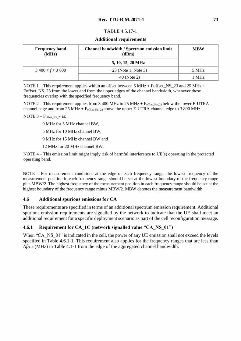
Rec. ITU-R M.2071-1 73
TABLE 4.5.17-1
Additional requirements
Frequency band
(MHz)
Channel bandwidth / Spectrum emission limit
(dBm)
MBW
5, 10, 15, 20 MHz
3 400 ≤ f ≤ 3 800 −23 (Note 1, Note 3) 5 MHz
−40 (Note 2) 1 MHz
NOTE 1 – This requirement applies within an offset between 5 MHz + Foffset_NS_23 and 25 MHz +
Foffset_NS_23 from the lower and from the upper edges of the channel bandwidth, whenever these
frequencies overlap with the specified frequency band.
NOTE 2 – This requirement applies from 3 400 MHz to 25 MHz + Foffset_NS_23 below the lower E-UTRA
channel edge and from 25 MHz + Foffset_NS_23 above the upper E-UTRA channel edge to 3 800 MHz.
NOTE 3 – Foffset_NS_23 is:
0 MHz for 5 MHz channel BW,
5 MHz for 10 MHz channel BW,
9 MHz for 15 MHz channel BW and
12 MHz for 20 MHz channel BW.
NOTE 4 – This emission limit might imply risk of harmful interference to UE(s) operating in the protected
operating band.
NOTE – For measurement conditions at the edge of each frequency range, the lowest frequency of the
measurement position in each frequency range should be set at the lowest boundary of the frequency range
plus MBW/2. The highest frequency of the measurement position in each frequency range should be set at the
highest boundary of the frequency range minus MBW/2. MBW denotes the measurement bandwidth.
4.6 Additional spurious emissions for CA
These requirements are specified in terms of an additional spectrum emission requirement. Additional
spurious emission requirements are signalled by the network to indicate that the UE shall meet an
additional requirement for a specific deployment scenario as part of the cell reconfiguration message.
4.6.1 Requirement for CA_1C (network signalled value “CA_NS_01”)
When “CA_NS_01” is indicated in the cell, the power of any UE emission shall not exceed the levels
specified in Table 4.6.1-1. This requirement also applies for the frequency ranges that are less than
ΔfOoB (MHz) in Table 4.1-1 from the edge of the aggregated channel bandwidth.

74 Rec. ITU-R M.2071-1
TABLE 4.6.1-1
Additional requirements (PHS)
Protected band Frequency range
(MHz)
Maximum level
(dBm)
MBW
(MHz) Note
E-UTRA band 34 FDL_low − FDL_high −50 1
Frequency range 1 884.5 − 1 919.6 −41 0.3 1
NOTE 1 – Applicable when the aggregated channel bandwidth is confined within frequency range
1 940-1 980 MHz.
NOTE – For measurement conditions at the edge of each frequency range, the lowest frequency of the
measurement position in each frequency range should be set at the lowest boundary of the frequency range
plus MBW/2. The highest frequency of the measurement position in each frequency range should be set at the
highest boundary of the frequency range minus MBW/2. MBW denotes the MBW (300 kHz).
4.6.2 Requirement for CA_1C (network signalled value “CA_NS_02”)
When “CA_NS_02” is indicated in the cell, the power of any UE emission shall not exceed the levels
specified in Table 4.6.2-1. This requirement also applies for the frequency ranges that are less than
ΔfOoB (MHz) in Table 4.1-1 from the edge of the aggregated channel bandwidth.
TABLE 4.6.2-1
Additional requirements
Protected band Frequency range
(MHz)
Maximum level
(dBm)
MBW
(MHz)
E−UTRA band 34 FDL_low − FDL_high −50 1
Frequency range 1 900 − 1 915 −15.5 5
Frequency range 1 915 − 1 920 +1.6 5
4.6.3 Requirement for CA_1C (network signalled value “CA_NS_03”)
When “CA_NS_03” is indicated in the cell, the power of any UE emission shall not exceed the levels
specified in Table 4.6.3-1. This requirement also applies for the frequency ranges that are less than
ΔfOoB (MHz) in Table 4.1-1 from the edge of the aggregated channel bandwidth.
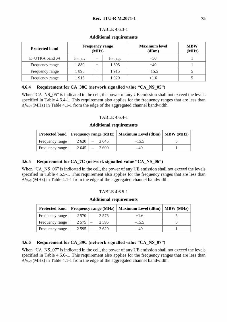
Rec. ITU-R M.2071-1 75
TABLE 4.6.3-1
Additional requirements
Protected band Frequency range
(MHz)
Maximum level
(dBm)
MBW
(MHz)
E−UTRA band 34 FDL_low − FDL_high −50 1
Frequency range 1 880 − 1 895 −40 1
Frequency range 1 895 − 1 915 −15.5 5
Frequency range 1 915 − 1 920 +1.6 5
4.6.4 Requirement for CA_38C (network signalled value “CA_NS_05”)
When “CA_NS_05” is indicated in the cell, the power of any UE emission shall not exceed the levels
specified in Table 4.6.4-1. This requirement also applies for the frequency ranges that are less than
ΔfOoB (MHz) in Table 4.1-1 from the edge of the aggregated channel bandwidth.
TABLE 4.6.4-1
Additional requirements
Protected band Frequency range (MHz) Maximum Level (dBm) MBW (MHz)
Frequency range 2 620 – 2 645 –15.5 5
Frequency range 2 645 – 2 690 –40 1
4.6.5 Requirement for CA_7C (network signalled value “CA_NS_06”)
When “CA_NS_06” is indicated in the cell, the power of any UE emission shall not exceed the levels
specified in Table 4.6.5-1. This requirement also applies for the frequency ranges that are less than
ΔfOoB (MHz) in Table 4.1-1 from the edge of the aggregated channel bandwidth.
TABLE 4.6.5-1
Additional requirements
Protected band Frequency range (MHz) Maximum Level (dBm) MBW (MHz)
Frequency range 2 570 – 2 575 +1.6 5
Frequency range 2 575 – 2 595 –15.5 5
Frequency range 2 595 – 2 620 –40 1
4.6.6 Requirement for CA_39C (network signalled value “CA_NS_07”)
When “CA_NS_07” is indicated in the cell, the power of any UE emission shall not exceed the levels
specified in Table 4.6.6-1. This requirement also applies for the frequency ranges that are less than
ΔfOoB (MHz) in Table 4.1-1 from the edge of the aggregated channel bandwidth.
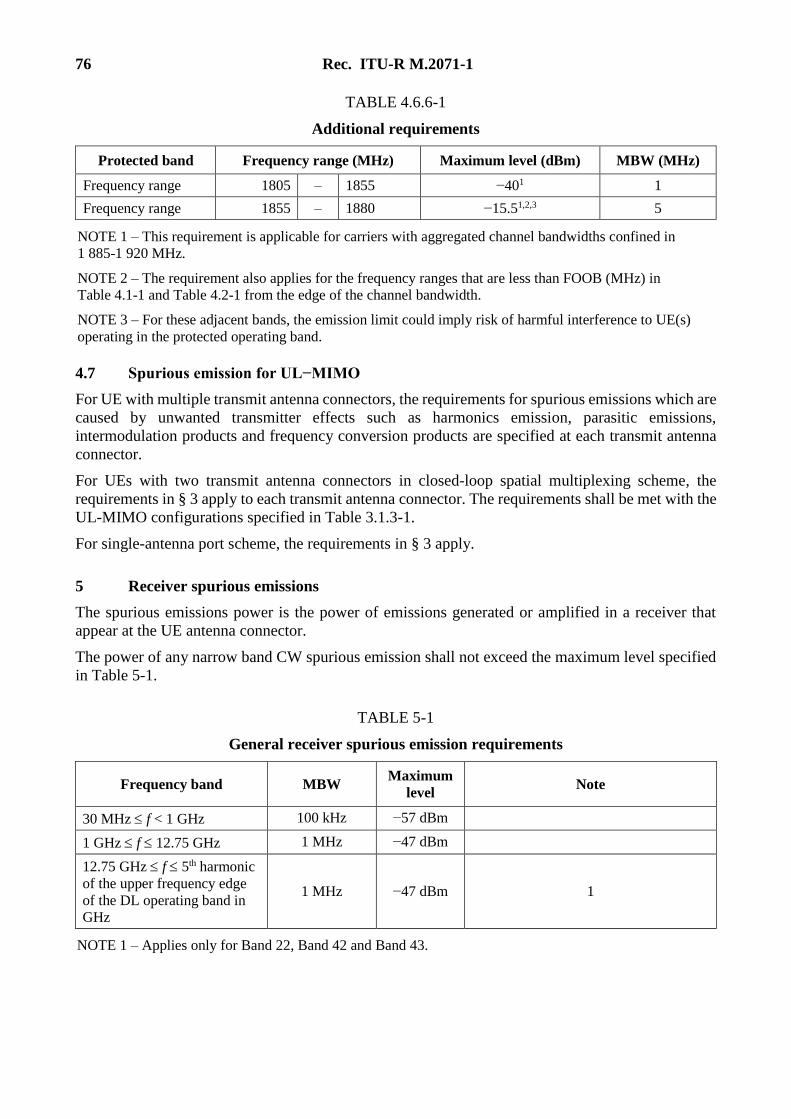
76 Rec. ITU-R M.2071-1
TABLE 4.6.6-1
Additional requirements
Protected band Frequency range (MHz) Maximum level (dBm) MBW (MHz)
Frequency range 1805 – 1855 −401 1
Frequency range 1855 – 1880 −15.51,2,3 5
NOTE 1 – This requirement is applicable for carriers with aggregated channel bandwidths confined in
1 885-1 920 MHz.
NOTE 2 – The requirement also applies for the frequency ranges that are less than FOOB (MHz) in
Table 4.1-1 and Table 4.2-1 from the edge of the channel bandwidth.
NOTE 3 – For these adjacent bands, the emission limit could imply risk of harmful interference to UE(s)
operating in the protected operating band.
4.7 Spurious emission for UL−MIMO
For UE with multiple transmit antenna connectors, the requirements for spurious emissions which are
caused by unwanted transmitter effects such as harmonics emission, parasitic emissions,
intermodulation products and frequency conversion products are specified at each transmit antenna
connector.
For UEs with two transmit antenna connectors in closed-loop spatial multiplexing scheme, the
requirements in § 3 apply to each transmit antenna connector. The requirements shall be met with the
UL-MIMO configurations specified in Table 3.1.3-1.
For single-antenna port scheme, the requirements in § 3 apply.
5 Receiver spurious emissions
The spurious emissions power is the power of emissions generated or amplified in a receiver that
appear at the UE antenna connector.
The power of any narrow band CW spurious emission shall not exceed the maximum level specified
in Table 5-1.
TABLE 5-1
General receiver spurious emission requirements
Frequency band MBW Maximum
level Note
30 MHz f < 1 GHz 100 kHz −57 dBm
1 GHz f 12.75 GHz 1 MHz −47 dBm
12.75 GHz f 5th harmonic
of the upper frequency edge
of the DL operating band in
GHz
1 MHz −47 dBm 1
NOTE 1 – Applies only for Band 22, Band 42 and Band 43.
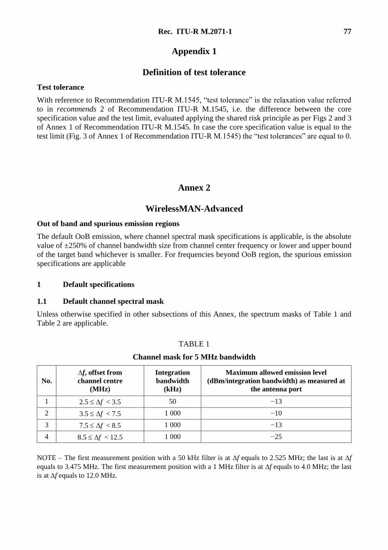
Rec. ITU-R M.2071-1 77
Appendix 1
Definition of test tolerance
Test tolerance
With reference to Recommendation ITU-R M.1545, “test tolerance” is the relaxation value referred
to in recommends 2 of Recommendation ITU-R M.1545, i.e. the difference between the core
specification value and the test limit, evaluated applying the shared risk principle as per Figs 2 and 3
of Annex 1 of Recommendation ITU-R M.1545. In case the core specification value is equal to the
test limit (Fig. 3 of Annex 1 of Recommendation ITU-R M.1545) the “test tolerances” are equal to 0.
Annex 2
WirelessMAN-Advanced
Out of band and spurious emission regions
The default OoB emission, where channel spectral mask specifications is applicable, is the absolute
value of ±250% of channel bandwidth size from channel center frequency or lower and upper bound
of the target band whichever is smaller. For frequencies beyond OoB region, the spurious emission
specifications are applicable
1 Default specifications
1.1 Default channel spectral mask
Unless otherwise specified in other subsections of this Annex, the spectrum masks of Table 1 and
Table 2 are applicable.
TABLE 1
Channel mask for 5 MHz bandwidth
No.
∆f, offset from
channel centre
(MHz)
Integration
bandwidth
(kHz)
Maximum allowed emission level
(dBm/integration bandwidth) as measured at
the antenna port
1 2.5 Δf < 3.5 50 −13
2 3.5 Δf < 7.5 1 000 −10
3 7.5 Δf < 8.5 1 000 −13
4 8.5 Δf < 12.5 1 000 −25
NOTE – The first measurement position with a 50 kHz filter is at f equals to 2.525 MHz; the last is at f
equals to 3.475 MHz. The first measurement position with a 1 MHz filter is at f equals to 4.0 MHz; the last
is at f equals to 12.0 MHz.
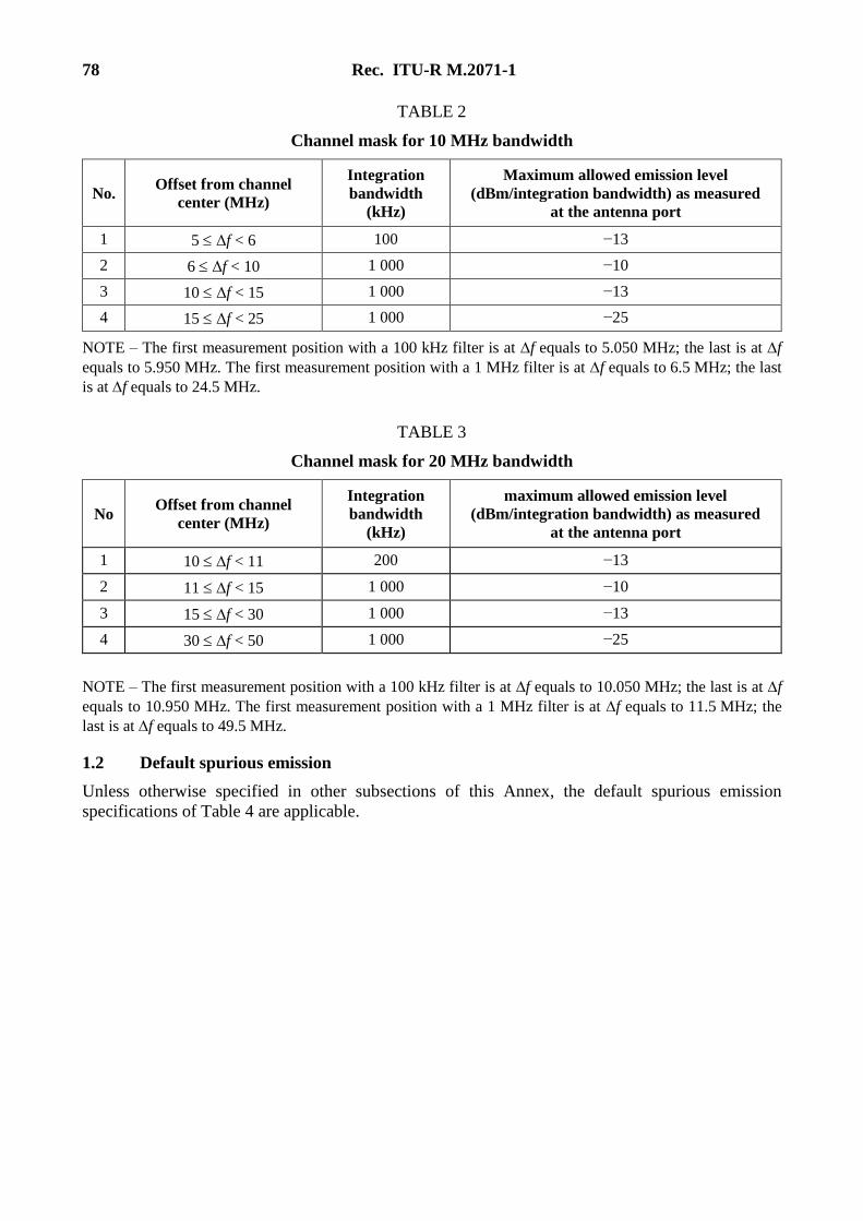
78 Rec. ITU-R M.2071-1
TABLE 2
Channel mask for 10 MHz bandwidth
No. Offset from channel
center (MHz)
Integration
bandwidth
(kHz)
Maximum allowed emission level
(dBm/integration bandwidth) as measured
at the antenna port
1 5 Δf < 6 100 −13
2 6 Δf < 10 1 000 −10
3 10 Δf < 15 1 000 −13
4 15 Δf < 25 1 000 −25
NOTE – The first measurement position with a 100 kHz filter is at f equals to 5.050 MHz; the last is at f
equals to 5.950 MHz. The first measurement position with a 1 MHz filter is at f equals to 6.5 MHz; the last
is at f equals to 24.5 MHz.
TABLE 3
Channel mask for 20 MHz bandwidth
No Offset from channel
center (MHz)
Integration
bandwidth
(kHz)
maximum allowed emission level
(dBm/integration bandwidth) as measured
at the antenna port
1 10 f < 11 200 −13
2 11 f < 15 1 000 −10
3 15 f < 30 1 000 −13
4 30 f < 50 1 000 −25
NOTE – The first measurement position with a 100 kHz filter is at f equals to 10.050 MHz; the last is at f
equals to 10.950 MHz. The first measurement position with a 1 MHz filter is at f equals to 11.5 MHz; the
last is at f equals to 49.5 MHz.
1.2 Default spurious emission
Unless otherwise specified in other subsections of this Annex, the default spurious emission
specifications of Table 4 are applicable.
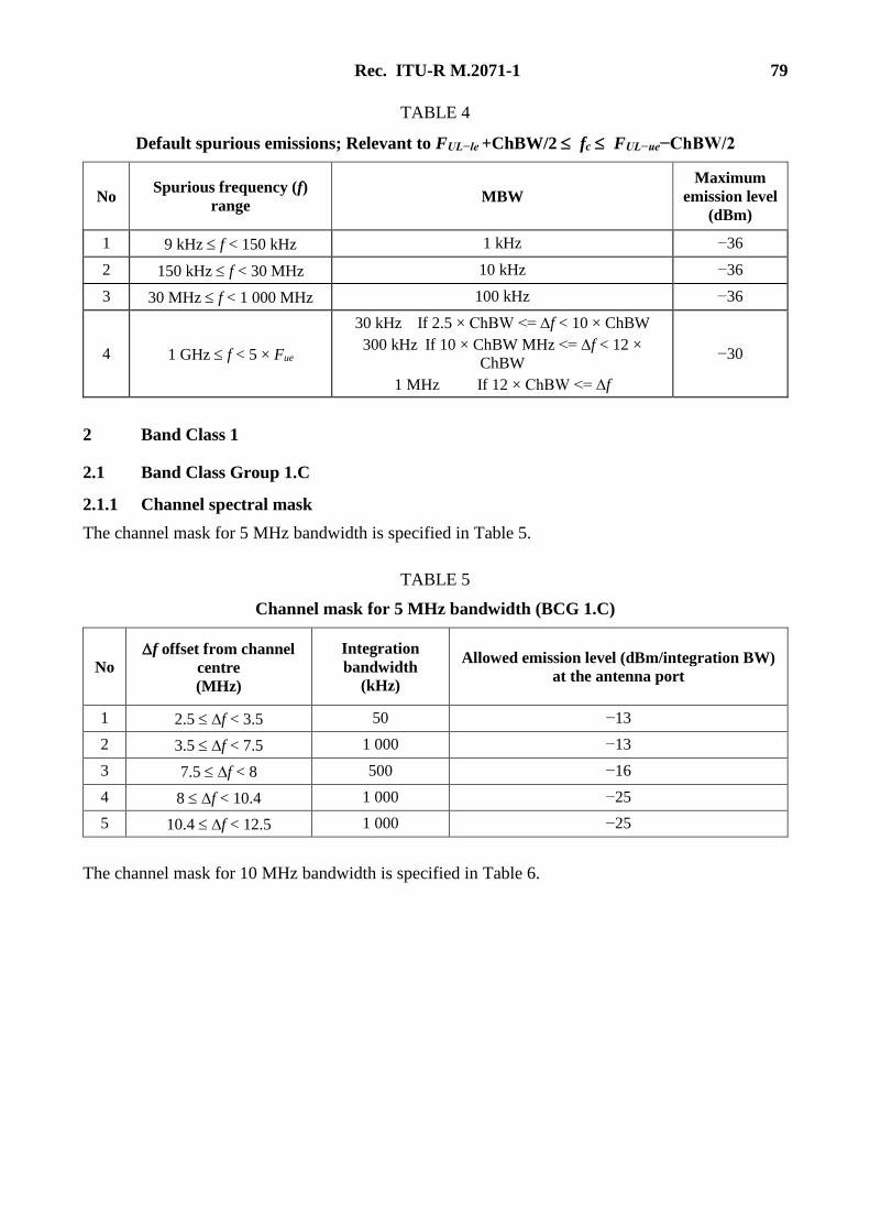
Rec. ITU-R M.2071-1 79
TABLE 4
Default spurious emissions; Relevant to FUL−le +ChBW/2 fc FUL−ue−ChBW/2
No Spurious frequency (f)
range MBW
Maximum
emission level
(dBm)
1 9 kHz f < 150 kHz 1 kHz −36
2 150 kHz f < 30 MHz 10 kHz −36
3 30 MHz f < 1 000 MHz 100 kHz −36
4 1 GHz f < 5 × Fue
30 kHz If 2.5 × ChBW <= ∆f < 10 × ChBW
300 kHz If 10 × ChBW MHz <= ∆f < 12 ×
ChBW
1 MHz If 12 × ChBW <= ∆f
−30
2 Band Class 1
2.1 Band Class Group 1.C
2.1.1 Channel spectral mask
The channel mask for 5 MHz bandwidth is specified in Table 5.
TABLE 5
Channel mask for 5 MHz bandwidth (BCG 1.C)
No
f offset from channel
centre
(MHz)
Integration
bandwidth
(kHz)
Allowed emission level (dBm/integration BW)
at the antenna port
1 2.5 f < 3.5 50 −13
2 3.5 f < 7.5 1 000 −13
3 7.5 f < 8 500 −16
4 8 f < 10.4 1 000 −25
5 10.4 f < 12.5 1 000 −25
The channel mask for 10 MHz bandwidth is specified in Table 6.
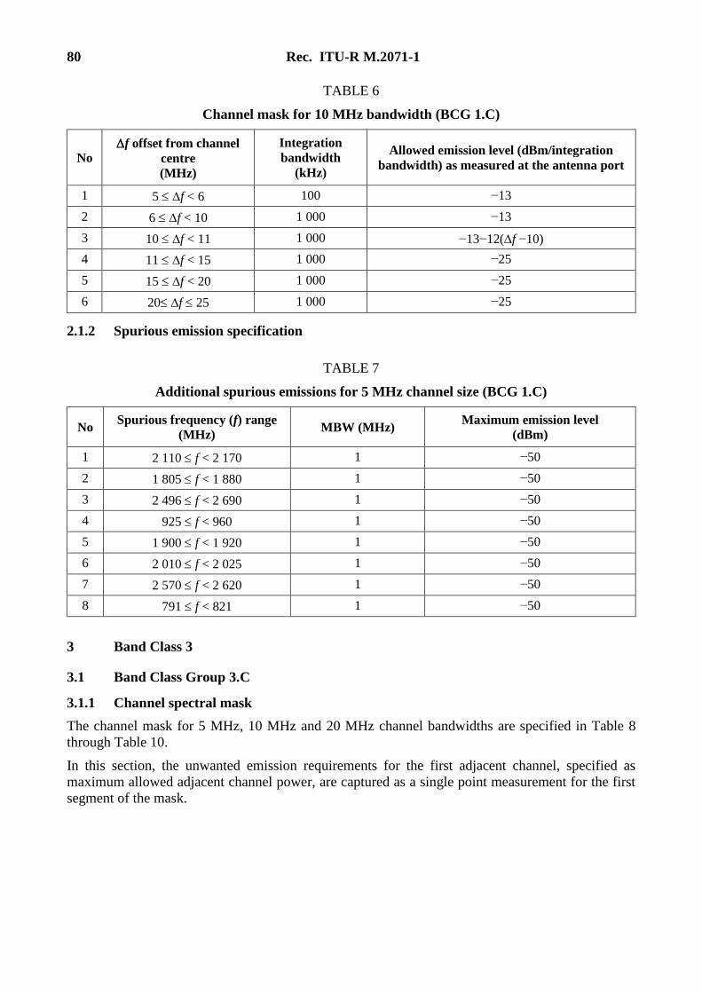
80 Rec. ITU-R M.2071-1
TABLE 6
Channel mask for 10 MHz bandwidth (BCG 1.C)
No
f offset from channel
centre
(MHz)
Integration
bandwidth
(kHz)
Allowed emission level (dBm/integration
bandwidth) as measured at the antenna port
1 5 f < 6 100 −13
2 6 f < 10 1 000 −13
3 10 f < 11 1 000 −13−12(f −10)
4 11 f < 15 1 000 −25
5 15 f < 20 1 000 −25
6 20 f 25 1 000 −25
2.1.2 Spurious emission specification
TABLE 7
Additional spurious emissions for 5 MHz channel size (BCG 1.C)
No Spurious frequency (f) range
(MHz) MBW (MHz)
Maximum emission level
(dBm)
1 2 110 f < 2 170 1 −50
2 1 805 f < 1 880 1 −50
3 2 496 f < 2 690 1 −50
4 925 f < 960 1 −50
5 1 900 f < 1 920 1 −50
6 2 010 f < 2 025 1 −50
7 2 570 f < 2 620 1 −50
8 791 f < 821 1 −50
3 Band Class 3
3.1 Band Class Group 3.C
3.1.1 Channel spectral mask
The channel mask for 5 MHz, 10 MHz and 20 MHz channel bandwidths are specified in Table 8
through Table 10.
In this section, the unwanted emission requirements for the first adjacent channel, specified as
maximum allowed adjacent channel power, are captured as a single point measurement for the first
segment of the mask.
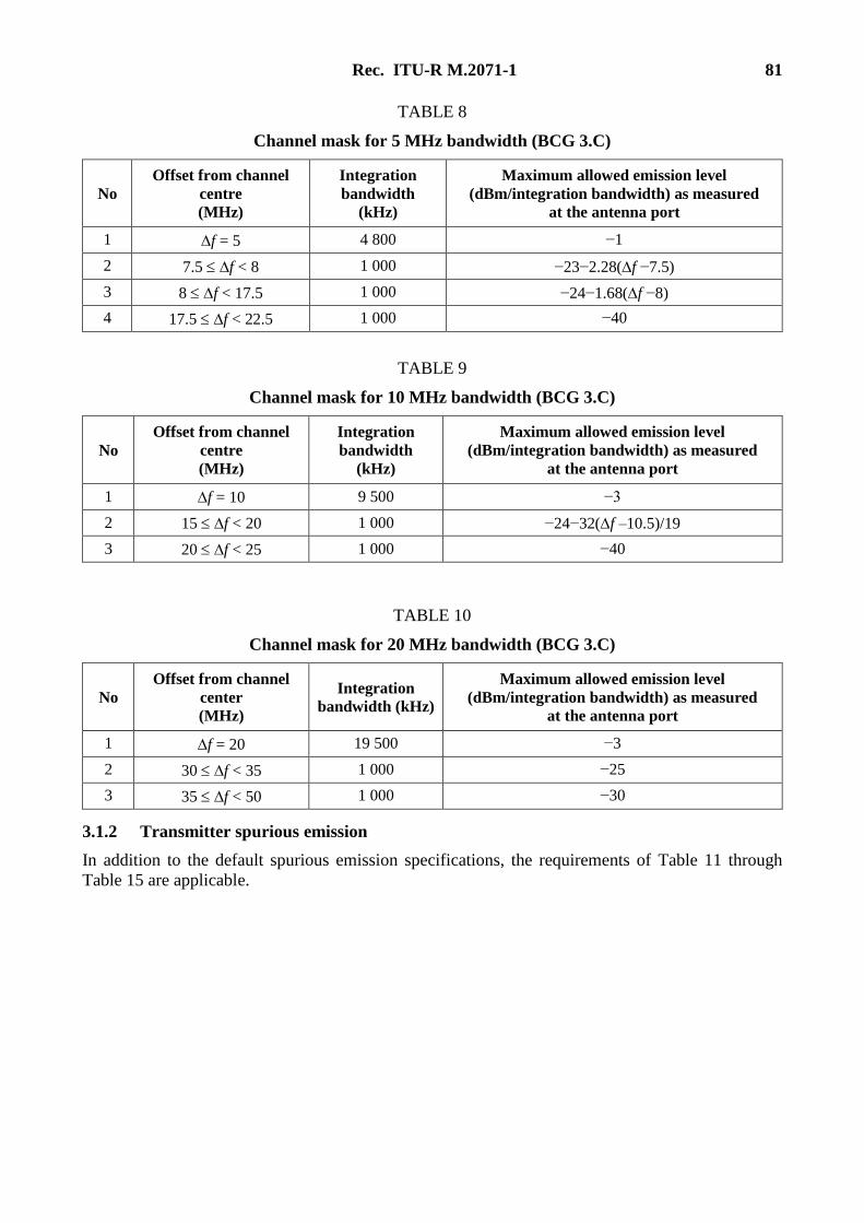
Rec. ITU-R M.2071-1 81
TABLE 8
Channel mask for 5 MHz bandwidth (BCG 3.C)
No
Offset from channel
centre
(MHz)
Integration
bandwidth
(kHz)
Maximum allowed emission level
(dBm/integration bandwidth) as measured
at the antenna port
1 f = 5 4 800 −1
2 7.5 f < 8 1 000 −23−2.28(f −7.5)
3 8 f < 17.5 1 000 −24−1.68(f −8)
4 17.5 f < 22.5 1 000 −40
TABLE 9
Channel mask for 10 MHz bandwidth (BCG 3.C)
No
Offset from channel
centre
(MHz)
Integration
bandwidth
(kHz)
Maximum allowed emission level
(dBm/integration bandwidth) as measured
at the antenna port
1 f = 10 9 500 −3
2 15 f < 20 1 000 −24−32(f –10.5)/19
3 20 f < 25 1 000 −40
TABLE 10
Channel mask for 20 MHz bandwidth (BCG 3.C)
No
Offset from channel
center
(MHz)
Integration
bandwidth (kHz)
Maximum allowed emission level
(dBm/integration bandwidth) as measured
at the antenna port
1 f = 20 19 500 −3
2 30 f < 35 1 000 −25
3 35 f < 50 1 000 −30
3.1.2 Transmitter spurious emission
In addition to the default spurious emission specifications, the requirements of Table 11 through
Table 15 are applicable.
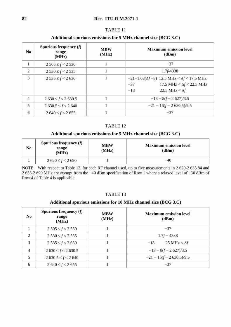
82 Rec. ITU-R M.2071-1
TABLE 11
Additional spurious emissions for 5 MHz channel size (BCG 3.C)
No
Spurious frequency (f)
range
(MHz)
MBW
(MHz)
Maximum emission level
(dBm)
1 2 505 f < 2 530 1 −37
2 2 530 f < 2 535 1 1.7f-4338
3 2 535 f < 2 630 1 −21−1.68(f −8) 12.5 MHz < f < 17.5 MHz
−37 17.5 MHz < f < 22.5 MHz
−18 22.5 MHz < f
4 2 630 f < 2 630.5 1 −13 − 8(f − 2 627)/3.5
5 2 630.5 f < 2 640 1 −21 − 16(f − 2 630.5)/9.5
6 2 640 f < 2 655 1 −37
TABLE 12
Additional spurious emissions for 5 MHz channel size (BCG 3.C)
No
Spurious frequency (f)
range
(MHz)
MBW
(MHz)
Maximum emission level
(dBm)
1 2 620 f < 2 690 1 −40
NOTE – With respect to Table 12, for each RF channel used, up to five measurements in 2 620-2 635.84 and
2 655-2 690 MHz are exempt from the −40 dBm specification of Row 1 where a relaxed level of −30 dBm of
Row 4 of Table 4 is applicable.
TABLE 13
Additional spurious emissions for 10 MHz channel size (BCG 3.C)
No
Spurious frequency (f)
range
(MHz)
MBW
(MHz)
Maximum emission level
(dBm)
1 2 505 f < 2 530 1 −37
2 2 530 f < 2 535 1 1.7f − 4338
3 2 535 f < 2 630 1 −18 25 MHz < f
4 2 630 f < 2 630.5 1 −13 − 8(f − 2 627)/3.5
5 2 630.5 f < 2 640 1 −21 − 16(f − 2 630.5)/9.5
6 2 640 f < 2 655 1 −37
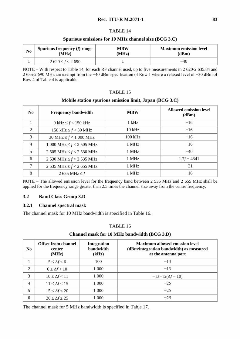
Rec. ITU-R M.2071-1 83
TABLE 14
Spurious emissions for 10 MHz channel size (BCG 3.C)
No Spurious frequency (f) range
(MHz)
MBW
(MHz)
Maximum emission level
(dBm)
1 2 620 f < 2 690 1 −40
NOTE – With respect to Table 14, for each RF channel used, up to five measurements in 2 620-2 635.84 and
2 655-2 690 MHz are exempt from the −40 dBm specification of Row 1 where a relaxed level of −30 dBm of
Row 4 of Table 4 is applicable.
TABLE 15
Mobile station spurious emission limit, Japan (BCG 3.C)
No Frequency bandwidth MBW Allowed emission level
(dBm)
1 9 kHz f < 150 kHz 1 kHz −16
2 150 kHz f < 30 MHz 10 kHz −16
3 30 MHz f < 1 000 MHz 100 kHz −16
4 1 000 MHz f < 2 505 MHz 1 MHz −16
5 2 505 MHz f < 2 530 MHz 1 MHz −40
6 2 530 MHz f < 2 535 MHz 1 MHz 1.7f − 4341
7 2 535 MHz f < 2 655 MHz 1 MHz −21
8 2 655 MHz f 1 MHz −16
NOTE – The allowed emission level for the frequency band between 2 535 MHz and 2 655 MHz shall be
applied for the frequency range greater than 2.5 times the channel size away from the centre frequency.
3.2 Band Class Group 3.D
3.2.1 Channel spectral mask
The channel mask for 10 MHz bandwidth is specified in Table 16.
TABLE 16
Channel mask for 10 MHz bandwidth (BCG 3.D)
No
Offset from channel
center
(MHz)
Integration
bandwidth
(kHz)
Maximum allowed emission level
(dBm/integration bandwidth) as measured
at the antenna port
1 5 f < 6 100 −13
2 6 f < 10 1 000 −13
3 10 f < 11 1 000 −13−12(f − 10)
4 11 f < 15 1 000 −25
5 15 f < 20 1 000 −25
6 20 f 25 1 000 −25
The channel mask for 5 MHz bandwidth is specified in Table 17.
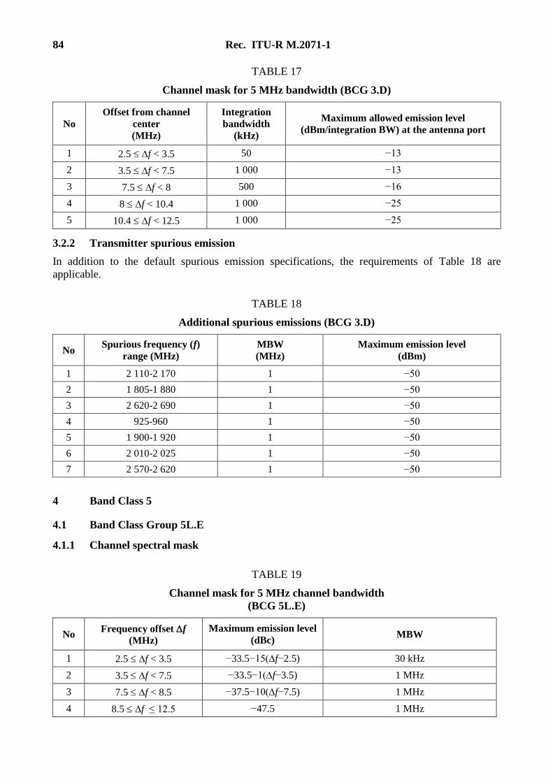
84 Rec. ITU-R M.2071-1
TABLE 17
Channel mask for 5 MHz bandwidth (BCG 3.D)
No
Offset from channel
center
(MHz)
Integration
bandwidth
(kHz)
Maximum allowed emission level
(dBm/integration BW) at the antenna port
1 2.5 f < 3.5 50 −13
2 3.5 f < 7.5 1 000 −13
3 7.5 f < 8 500 −16
4 8 f < 10.4 1 000 −25
5 10.4 f < 12.5 1 000 −25
3.2.2 Transmitter spurious emission
In addition to the default spurious emission specifications, the requirements of Table 18 are
applicable.
TABLE 18
Additional spurious emissions (BCG 3.D)
No Spurious frequency (f)
range (MHz)
MBW
(MHz)
Maximum emission level
(dBm)
1 2 110-2 170 1 −50
2 1 805-1 880 1 −50
3 2 620-2 690 1 −50
4 925-960 1 −50
5 1 900-1 920 1 −50
6 2 010-2 025 1 −50
7 2 570-2 620 1 −50
4 Band Class 5
4.1 Band Class Group 5L.E
4.1.1 Channel spectral mask
TABLE 19
Channel mask for 5 MHz channel bandwidth
(BCG 5L.E)
No Frequency offset f
(MHz)
Maximum emission level
(dBc) MBW
1 2.5 f < 3.5 −33.5−15(∆f−2.5) 30 kHz
2 3.5 f < 7.5 −33.5−1(∆f−3.5) 1 MHz
3 7.5 f < 8.5 −37.5−10(∆f−7.5) 1 MHz
4 8.5 f ≤ 12.5 −47.5 1 MHz
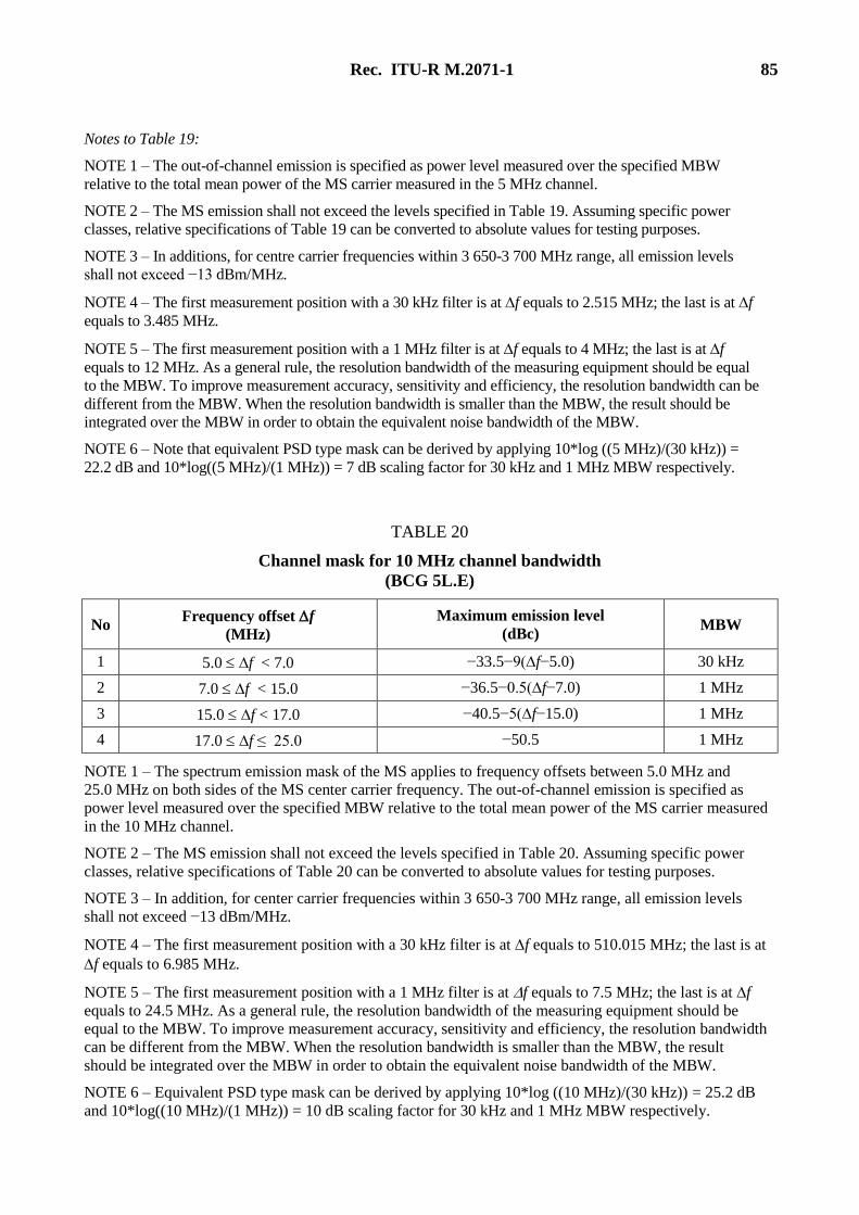
Rec. ITU-R M.2071-1 85
Notes to Table 19:
NOTE 1 – The out-of-channel emission is specified as power level measured over the specified MBW
relative to the total mean power of the MS carrier measured in the 5 MHz channel.
NOTE 2 – The MS emission shall not exceed the levels specified in Table 19. Assuming specific power
classes, relative specifications of Table 19 can be converted to absolute values for testing purposes.
NOTE 3 – In additions, for centre carrier frequencies within 3 650-3 700 MHz range, all emission levels
shall not exceed −13 dBm/MHz.
NOTE 4 – The first measurement position with a 30 kHz filter is at f equals to 2.515 MHz; the last is at f
equals to 3.485 MHz.
NOTE 5 – The first measurement position with a 1 MHz filter is at f equals to 4 MHz; the last is at f
equals to 12 MHz. As a general rule, the resolution bandwidth of the measuring equipment should be equal
to the MBW. To improve measurement accuracy, sensitivity and efficiency, the resolution bandwidth can be
different from the MBW. When the resolution bandwidth is smaller than the MBW, the result should be
integrated over the MBW in order to obtain the equivalent noise bandwidth of the MBW.
NOTE 6 – Note that equivalent PSD type mask can be derived by applying 10*log ((5 MHz)/(30 kHz)) =
22.2 dB and 10*log((5 MHz)/(1 MHz)) = 7 dB scaling factor for 30 kHz and 1 MHz MBW respectively.
TABLE 20
Channel mask for 10 MHz channel bandwidth
(BCG 5L.E)
No Frequency offset f
(MHz)
Maximum emission level
(dBc) MBW
1 5.0 f < 7.0 −33.5−9(∆f−5.0) 30 kHz
2 7.0 f < 15.0 −36.5−0.5(∆f−7.0) 1 MHz
3 15.0 f < 17.0 −40.5−5(∆f−15.0) 1 MHz
4 17.0 f ≤ 25.0 −50.5 1 MHz
NOTE 1 – The spectrum emission mask of the MS applies to frequency offsets between 5.0 MHz and
25.0 MHz on both sides of the MS center carrier frequency. The out-of-channel emission is specified as
power level measured over the specified MBW relative to the total mean power of the MS carrier measured
in the 10 MHz channel.
NOTE 2 – The MS emission shall not exceed the levels specified in Table 20. Assuming specific power
classes, relative specifications of Table 20 can be converted to absolute values for testing purposes.
NOTE 3 – In addition, for center carrier frequencies within 3 650-3 700 MHz range, all emission levels
shall not exceed −13 dBm/MHz.
NOTE 4 – The first measurement position with a 30 kHz filter is at f equals to 510.015 MHz; the last is at
f equals to 6.985 MHz.
NOTE 5 – The first measurement position with a 1 MHz filter is at f equals to 7.5 MHz; the last is at f
equals to 24.5 MHz. As a general rule, the resolution bandwidth of the measuring equipment should be
equal to the MBW. To improve measurement accuracy, sensitivity and efficiency, the resolution bandwidth
can be different from the MBW. When the resolution bandwidth is smaller than the MBW, the result
should be integrated over the MBW in order to obtain the equivalent noise bandwidth of the MBW.
NOTE 6 – Equivalent PSD type mask can be derived by applying 10*log ((10 MHz)/(30 kHz)) = 25.2 dB
and 10*log((10 MHz)/(1 MHz)) = 10 dB scaling factor for 30 kHz and 1 MHz MBW respectively.
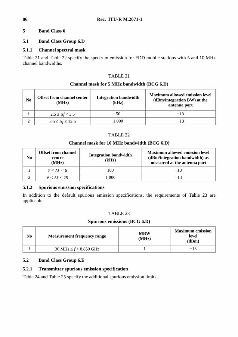
86 Rec. ITU-R M.2071-1
5 Band Class 6
5.1 Band Class Group 6.D
5.1.1 Channel spectral mask
Table 21 and Table 22 specify the spectrum emission for FDD mobile stations with 5 and 10 MHz
channel bandwidths.
TABLE 21
Channel mask for 5 MHz bandwidth (BCG 6.D)
No Offset from channel center
(MHz)
Integration bandwidth
(kHz)
Maximum allowed emission level
(dBm/integration BW) at the
antenna port
1 2.5 f < 3.5 50 −13
2 3.5 f 12.5 1 000 −13
TABLE 22
Channel mask for 10 MHz bandwidth (BCG 6.D)
No
Offset from channel
centre
(MHz)
Integration bandwidth
(kHz)
Maximum allowed emission level
(dBm/integration bandwidth) as
measured at the antenna port
1 5 f < 6 100 −13
2 6 f 25 1 000 −13
5.1.2 Spurious emission specifications
In addition to the default spurious emission specifications, the requirements of Table 23 are
applicable.
TABLE 23
Spurious emissions (BCG 6.D)
No Measurement frequency range MBW
(MHz)
Maximum emission
level
(dBm)
1 30 MHz f < 8.850 GHz 1 −13
5.2 Band Class Group 6.E
5.2.1 Transmitter spurious emission specification
Table 24 and Table 25 specify the additional spurious emission limits.
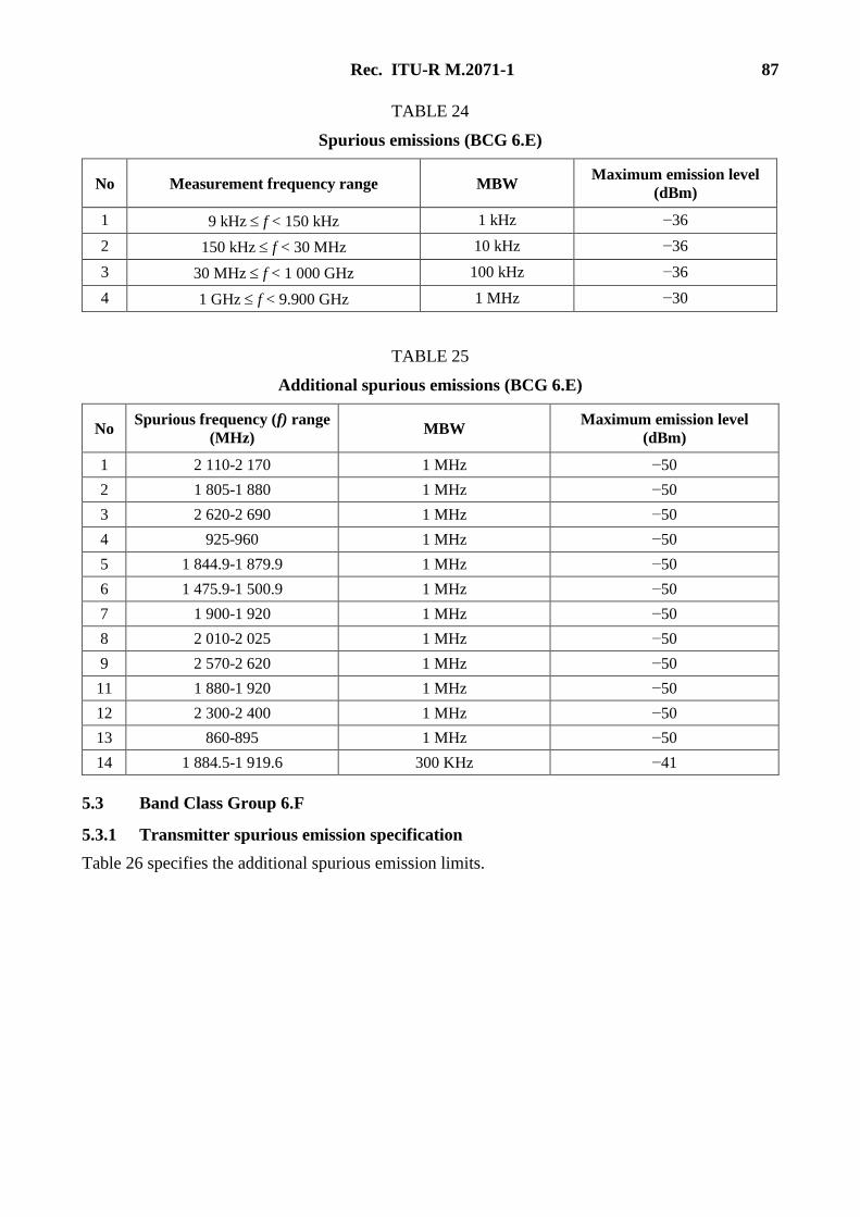
Rec. ITU-R M.2071-1 87
TABLE 24
Spurious emissions (BCG 6.E)
No Measurement frequency range MBW Maximum emission level
(dBm)
1 9 kHz f < 150 kHz 1 kHz −36
2 150 kHz f < 30 MHz 10 kHz −36
3 30 MHz f < 1 000 GHz 100 kHz −36
4 1 GHz f < 9.900 GHz 1 MHz −30
TABLE 25
Additional spurious emissions (BCG 6.E)
No Spurious frequency (f) range
(MHz) MBW
Maximum emission level
(dBm)
1 2 110-2 170 1 MHz −50
2 1 805-1 880 1 MHz −50
3 2 620-2 690 1 MHz −50
4 925-960 1 MHz −50
5 1 844.9-1 879.9 1 MHz −50
6 1 475.9-1 500.9 1 MHz −50
7 1 900-1 920 1 MHz −50
8 2 010-2 025 1 MHz −50
9 2 570-2 620 1 MHz −50
11 1 880-1 920 1 MHz −50
12 2 300-2 400 1 MHz −50
13 860-895 1 MHz −50
14 1 884.5-1 919.6 300 KHz −41
5.3 Band Class Group 6.F
5.3.1 Transmitter spurious emission specification
Table 26 specifies the additional spurious emission limits.
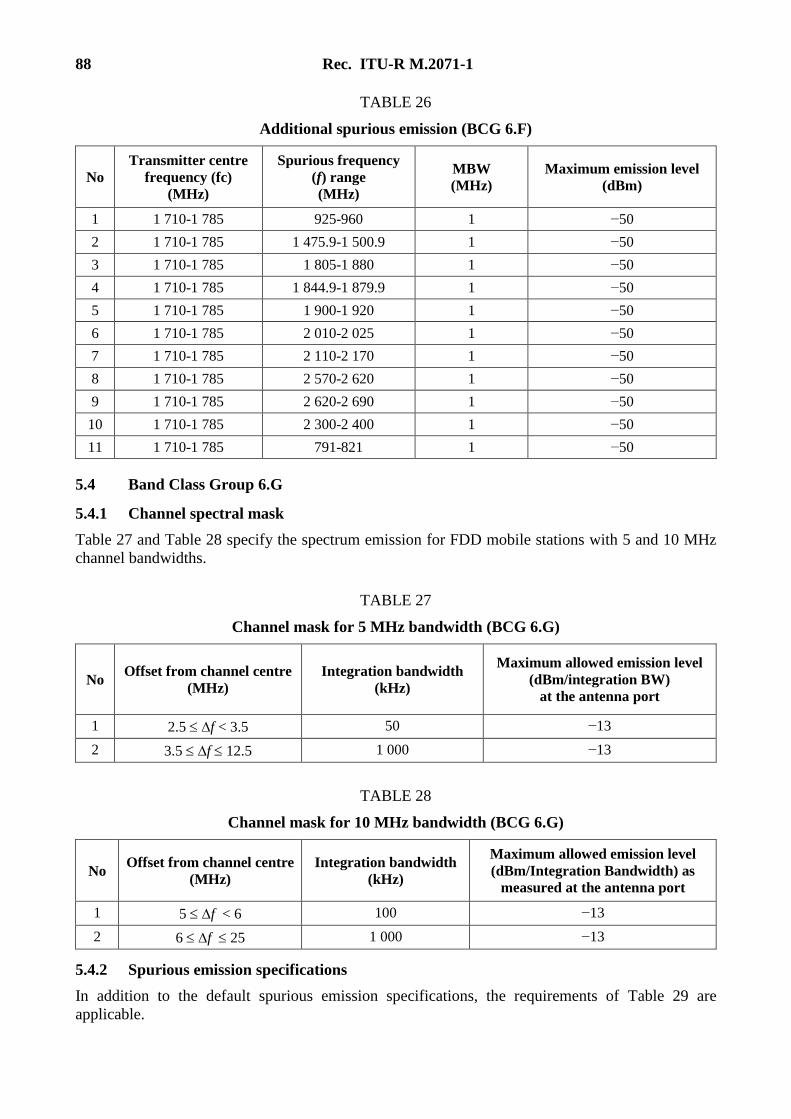
88 Rec. ITU-R M.2071-1
TABLE 26
Additional spurious emission (BCG 6.F)
No
Transmitter centre
frequency (fc)
(MHz)
Spurious frequency
(f) range
(MHz)
MBW
(MHz)
Maximum emission level
(dBm)
1 1 710-1 785 925-960 1 −50
2 1 710-1 785 1 475.9-1 500.9 1 −50
3 1 710-1 785 1 805-1 880 1 −50
4 1 710-1 785 1 844.9-1 879.9 1 −50
5 1 710-1 785 1 900-1 920 1 −50
6 1 710-1 785 2 010-2 025 1 −50
7 1 710-1 785 2 110-2 170 1 −50
8 1 710-1 785 2 570-2 620 1 −50
9 1 710-1 785 2 620-2 690 1 −50
10 1 710-1 785 2 300-2 400 1 −50
11 1 710-1 785 791-821 1 −50
5.4 Band Class Group 6.G
5.4.1 Channel spectral mask
Table 27 and Table 28 specify the spectrum emission for FDD mobile stations with 5 and 10 MHz
channel bandwidths.
TABLE 27
Channel mask for 5 MHz bandwidth (BCG 6.G)
No Offset from channel centre
(MHz)
Integration bandwidth
(kHz)
Maximum allowed emission level
(dBm/integration BW)
at the antenna port
1 2.5 f < 3.5 50 −13
2 3.5 f 12.5 1 000 −13
TABLE 28
Channel mask for 10 MHz bandwidth (BCG 6.G)
No Offset from channel centre
(MHz)
Integration bandwidth
(kHz)
Maximum allowed emission level
(dBm/Integration Bandwidth) as
measured at the antenna port
1 5 f < 6 100 −13
2 6 f 25 1 000 −13
5.4.2 Spurious emission specifications
In addition to the default spurious emission specifications, the requirements of Table 29 are
applicable.
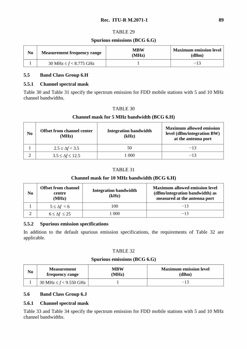
Rec. ITU-R M.2071-1 89
TABLE 29
Spurious emissions (BCG 6.G)
No Measurement frequency range MBW
(MHz)
Maximum emission level
(dBm)
1 30 MHz f < 8.775 GHz 1 −13
5.5 Band Class Group 6.H
5.5.1 Channel spectral mask
Table 30 and Table 31 specify the spectrum emission for FDD mobile stations with 5 and 10 MHz
channel bandwidths.
TABLE 30
Channel mask for 5 MHz bandwidth (BCG 6.H)
No Offset from channel center
(MHz)
Integration bandwidth
(kHz)
Maximum allowed emission
level (dBm/integration BW)
at the antenna port
1 2.5 f < 3.5 50 −13
2 3.5 f 12.5 1 000 −13
TABLE 31
Channel mask for 10 MHz bandwidth (BCG 6.H)
No
Offset from channel
centre
(MHz)
Integration bandwidth
(kHz)
Maximum allowed emission level
(dBm/integration bandwidth) as
measured at the antenna port
1 5 f < 6 100 −13
2 6 f 25 1 000 −13
5.5.2 Spurious emission specifications
In addition to the default spurious emission specifications, the requirements of Table 32 are
applicable.
TABLE 32
Spurious emissions (BCG 6.G)
No Measurement
frequency range
MBW
(MHz)
Maximum emission level
(dBm)
1 30 MHz f < 9.550 GHz 1 −13
5.6 Band Class Group 6.J
5.6.1 Channel spectral mask
Table 33 and Table 34 specify the spectrum emission for FDD mobile stations with 5 and 10 MHz
channel bandwidths.
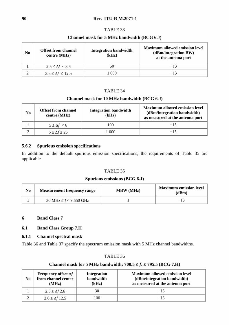
90 Rec. ITU-R M.2071-1
TABLE 33
Channel mask for 5 MHz bandwidth (BCG 6.J)
No Offset from channel
centre (MHz)
Integration bandwidth
(kHz)
Maximum allowed emission level
(dBm/integration BW)
at the antenna port
1 2.5 f < 3.5 50 −13
2 3.5 f 12.5 1 000 −13
TABLE 34
Channel mask for 10 MHz bandwidth (BCG 6.J)
No Offset from channel
centre (MHz)
Integration bandwidth
(kHz)
Maximum allowed emission level
(dBm/integration bandwidth)
as measured at the antenna port
1 5 f < 6 100 −13
2 6 f 25 1 000 −13
5.6.2 Spurious emission specifications
In addition to the default spurious emission specifications, the requirements of Table 35 are
applicable.
TABLE 35
Spurious emissions (BCG 6.J)
No Measurement frequency range MBW (MHz) Maximum emission level
(dBm)
1 30 MHz f < 9.550 GHz 1 −13
6 Band Class 7
6.1 Band Class Group 7.H
6.1.1 Channel spectral mask
Table 36 and Table 37 specify the spectrum emission mask with 5 MHz channel bandwidths.
TABLE 36
Channel mask for 5 MHz bandwidth: 700.5 fc 795.5 (BCG 7.H)
No
Frequency offset f
from channel center
(MHz)
Integration
bandwidth
(kHz)
Maximum allowed emission level
(dBm/integration bandwidth)
as measured at the antenna port
1 2.5 f 2.6 30 −13
2 2.6 f 12.5 100 −13
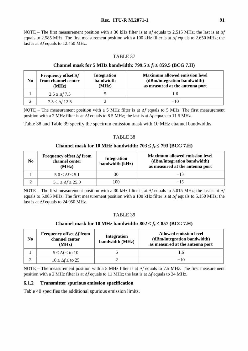
Rec. ITU-R M.2071-1 91
NOTE – The first measurement position with a 30 kHz filter is at f equals to 2.515 MHz; the last is at f
equals to 2.585 MHz. The first measurement position with a 100 kHz filter is at f equals to 2.650 MHz; the
last is at f equals to 12.450 MHz.
TABLE 37
Channel mask for 5 MHz bandwidth: 799.5 fc 859.5 (BCG 7.H)
No
Frequency offset f
from channel center
(MHz)
Integration
bandwidth
(MHz)
Maximum allowed emission level
(dBm/integration bandwidth)
as measured at the antenna port
1 2.5 f 7.5 5 1.6
2 7.5 f 12.5 2 −10
NOTE – The measurement position with a 5 MHz filter is at f equals to 5 MHz. The first measurement
position with a 2 MHz filter is at f equals to 8.5 MHz; the last is at f equals to 11.5 MHz.
Table 38 and Table 39 specify the spectrum emission mask with 10 MHz channel bandwidths.
TABLE 38
Channel mask for 10 MHz bandwidth: 703 fc 793 (BCG 7.H)
No Frequency offset f from
channel center
(MHz)
Integration
bandwidth (kHz)
Maximum allowed emission level
(dBm/integration bandwidth)
as measured at the antenna port
1 5.0 f < 5.1 30 −13
2 5.1 f 25.0 100 −13
NOTE – The first measurement position with a 30 kHz filter is at f equals to 5.015 MHz; the last is at f
equals to 5.085 MHz. The first measurement position with a 100 kHz filter is at f equals to 5.150 MHz; the
last is at f equals to 24.950 MHz.
TABLE 39
Channel mask for 10 MHz bandwidth: 802 fc 857 (BCG 7.H)
No
Frequency offset f from
channel center
(MHz)
Integration
bandwidth (MHz)
Allowed emission level
(dBm/integration bandwidth)
as measured at the antenna port
1 5 f < to 10 5 1.6
2 10 f to 25 2 −10
NOTE – The measurement position with a 5 MHz filter is at f equals to 7.5 MHz. The first measurement
position with a 2 MHz filter is at f equals to 11 MHz; the last is at f equals to 24 MHz.
6.1.2 Transmitter spurious emission specification
Table 40 specifies the additional spurious emission limits.
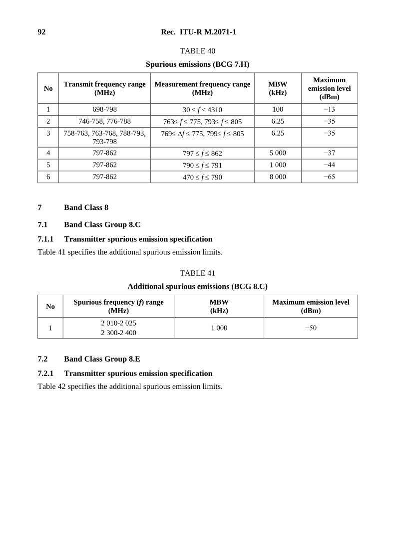
92 Rec. ITU-R M.2071-1
TABLE 40
Spurious emissions (BCG 7.H)
No Transmit frequency range
(MHz)
Measurement frequency range
(MHz)
MBW
(kHz)
Maximum
emission level
(dBm)
1 698-798 30 f < 4310 100 −13
2 746-758, 776-788 763 f 775, 793 f 805 6.25 −35
3 758-763, 763-768, 788-793,
793-798 769 f 775, 799 f 805 6.25 −35
4 797-862 797 f 862 5 000 −37
5 797-862 790 f 791 1 000 −44
6 797-862 470 f 790 8 000 −65
7 Band Class 8
7.1 Band Class Group 8.C
7.1.1 Transmitter spurious emission specification
Table 41 specifies the additional spurious emission limits.
TABLE 41
Additional spurious emissions (BCG 8.C)
No Spurious frequency (f) range
(MHz)
MBW
(kHz)
Maximum emission level
(dBm)
1 2 010-2 025
2 300-2 400 1 000 −50
7.2 Band Class Group 8.E
7.2.1 Transmitter spurious emission specification
Table 42 specifies the additional spurious emission limits.
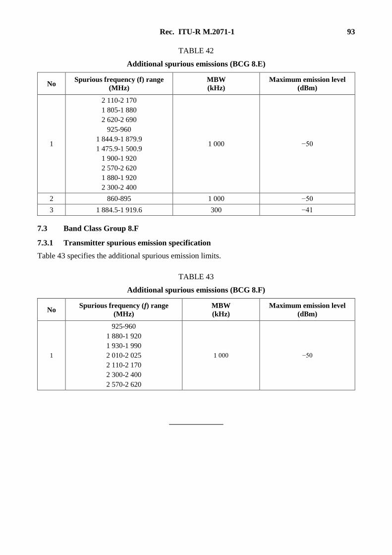
Rec. ITU-R M.2071-1 93
TABLE 42
Additional spurious emissions (BCG 8.E)
No Spurious frequency (f) range
(MHz)
MBW
(kHz)
Maximum emission level
(dBm)
1
2 110-2 170
1 805-1 880
2 620-2 690
925-960
1 844.9-1 879.9
1 475.9-1 500.9
1 900-1 920
2 570-2 620
1 880-1 920
2 300-2 400
1 000 −50
2 860-895 1 000 −50
3 1 884.5-1 919.6 300 −41
7.3 Band Class Group 8.F
7.3.1 Transmitter spurious emission specification
Table 43 specifies the additional spurious emission limits.
TABLE 43
Additional spurious emissions (BCG 8.F)
No Spurious frequency (f) range
(MHz)
MBW
(kHz)
Maximum emission level
(dBm)
1
925-960
1 880-1 920
1 930-1 990
2 010-2 025
2 110-2 170
2 300-2 400
2 570-2 620
1 000 −50