generators for wind power nov 2008 - IIT Bombaynpsc2008/NPSC_CD/Data/Tutorial 2... · 14/53...
53
Generators for wind power conversion Email : [email protected] B. G. Fernandes Department of Electrical Engineering Indian Institute of Technology, Bombay
Transcript of generators for wind power nov 2008 - IIT Bombaynpsc2008/NPSC_CD/Data/Tutorial 2... · 14/53...
Generators for wind power conversion
Email : [email protected]
B. G. FernandesDepartment of Electrical EngineeringIndian Institute of Technology, Bombay
Nov 2008 Generators for wind power conversion 2/53
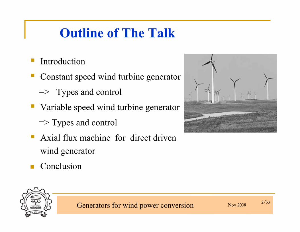
Outline of The Talk
Introduction
Constant speed wind turbine generator
=> Types and control
Variable speed wind turbine generator
=> Types and control
Axial flux machine for direct driven wind generator
Conclusion
Nov 2008 Generators for wind power conversion 3/53
Available wind Power
The amount of energy the wind turbine can produce is dependent on the wind regime where it is located and efficiency at which it captures energy
Wind regime is defined by three characteristics
=> Average wind velocity
=> The Weibull distribution of wind velocity
=> The shear of wind at the turbine location

Nov 2008 Generators for wind power conversion 4/53
Wind Resources in India
Nov 2008 Generators for wind power conversion 5/53
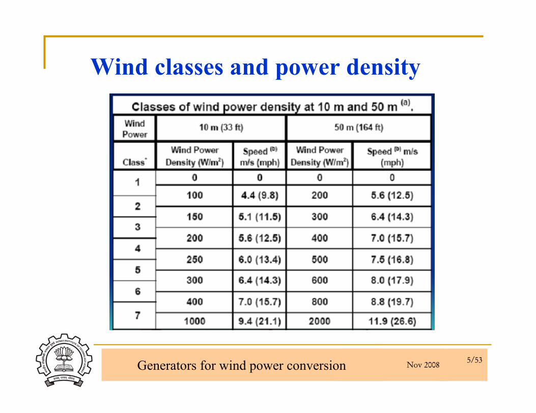
Wind classes and power density
Nov 2008 Generators for wind power conversion 6/53
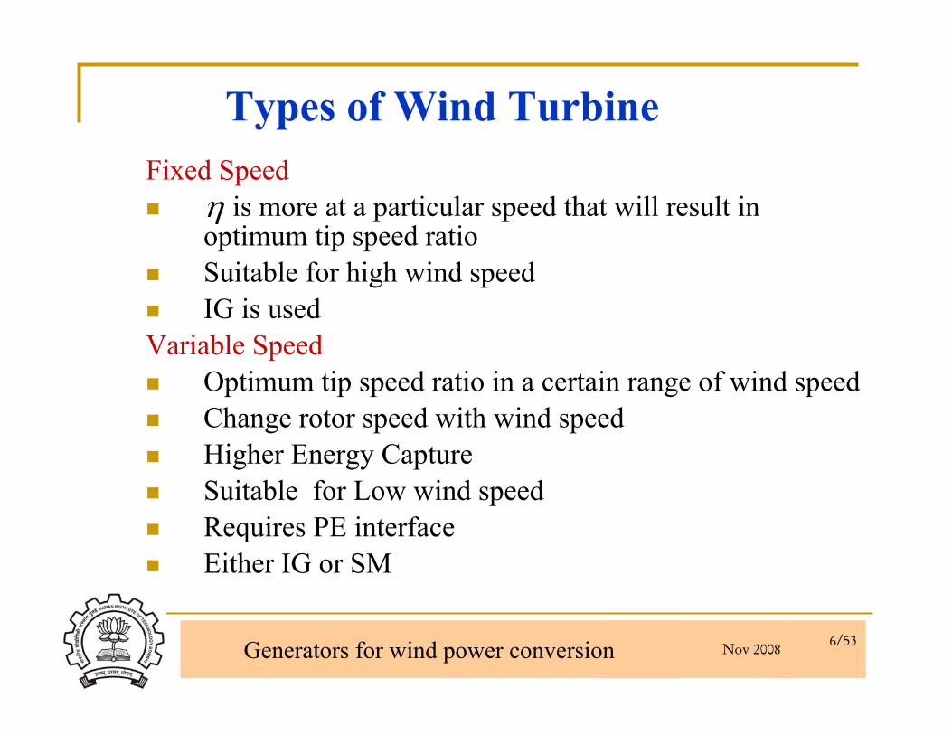
Types of Wind TurbineFixed Speed
is more at a particular speed that will result in optimum tip speed ratio Suitable for high wind speedIG is used
Variable SpeedOptimum tip speed ratio in a certain range of wind speedChange rotor speed with wind speed Higher Energy CaptureSuitable for Low wind speedRequires PE interfaceEither IG or SM
η

Nov 2008 Generators for wind power conversion 7/53
Wind Turbine Model
Power in Wind = Swept Area= Wind velocity= Air Density
3
21 AvPw ρ=
vρ
),( λβfCp =
Two dimensional characteristicsTwo dimensional characteristics
= Pitch angle= Pitch angleββλλ = Tip speed ratio= Tip speed ratio
=>Max. value of = 0.593=>Max. value of = 0.593=>Varies with=>Varies with ωω
AA

Nov 2008 Generators for wind power conversion 8/53
Contd..
3
3
(max)max
21
m
opt
mP
K
RACP
ω
λωρ
=
⎟⎟⎠
⎞⎜⎜⎝
⎛=∴
K => function of and turbine parameterρSensing rotor speed or frequency of output voltageit is possible to operate at CP(max)
∴
Turbine Output Power
vRmωλ =
mωR
pwCPP =
= Speed of( rotation )Wind Turbine
= Radius of rotating Wind Turbine
Nov 2008 Generators for wind power conversion 9/53
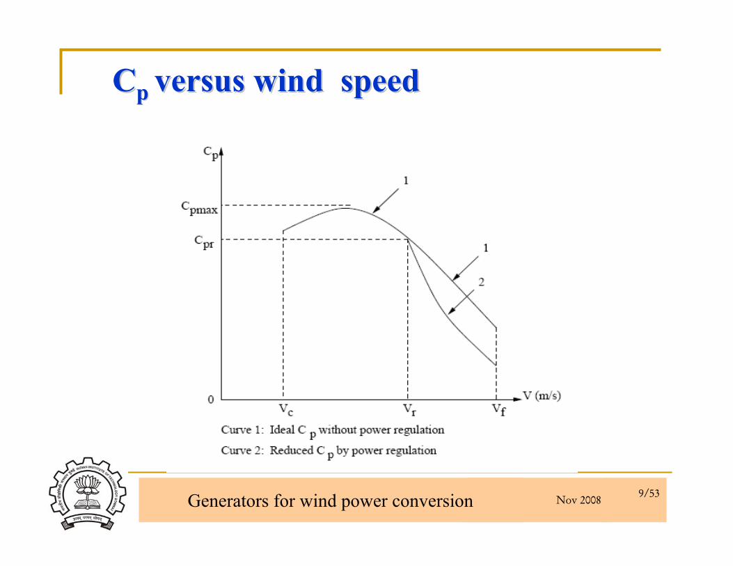
CCp p versus wind speedversus wind speed

Nov 2008 Generators for wind power conversion 10/53
Output power versus wind speedOutput power versus wind speed
Nov 2008 Generators for wind power conversion 11/53
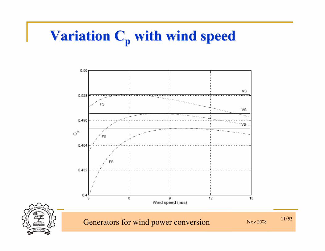
Variation CVariation Cpp with wind speedwith wind speed
Nov 2008 Generators for wind power conversion 12/53
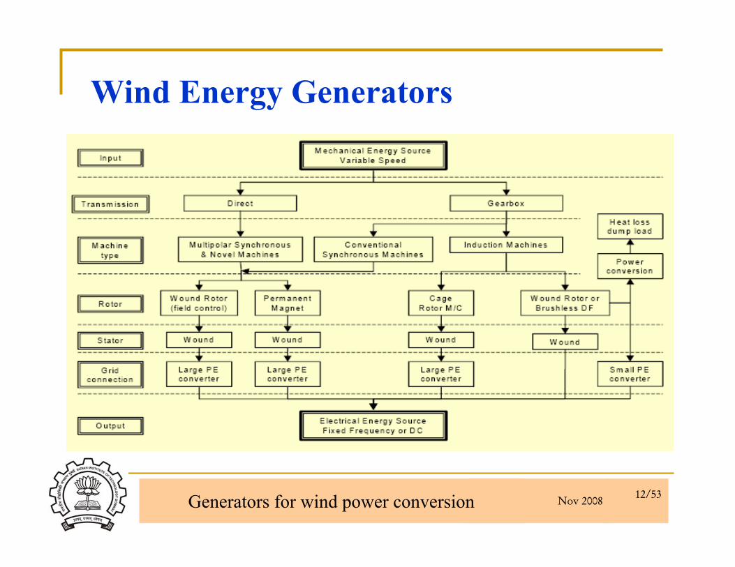
Wind Energy Generators
Nov 2008 Generators for wind power conversion 13/53
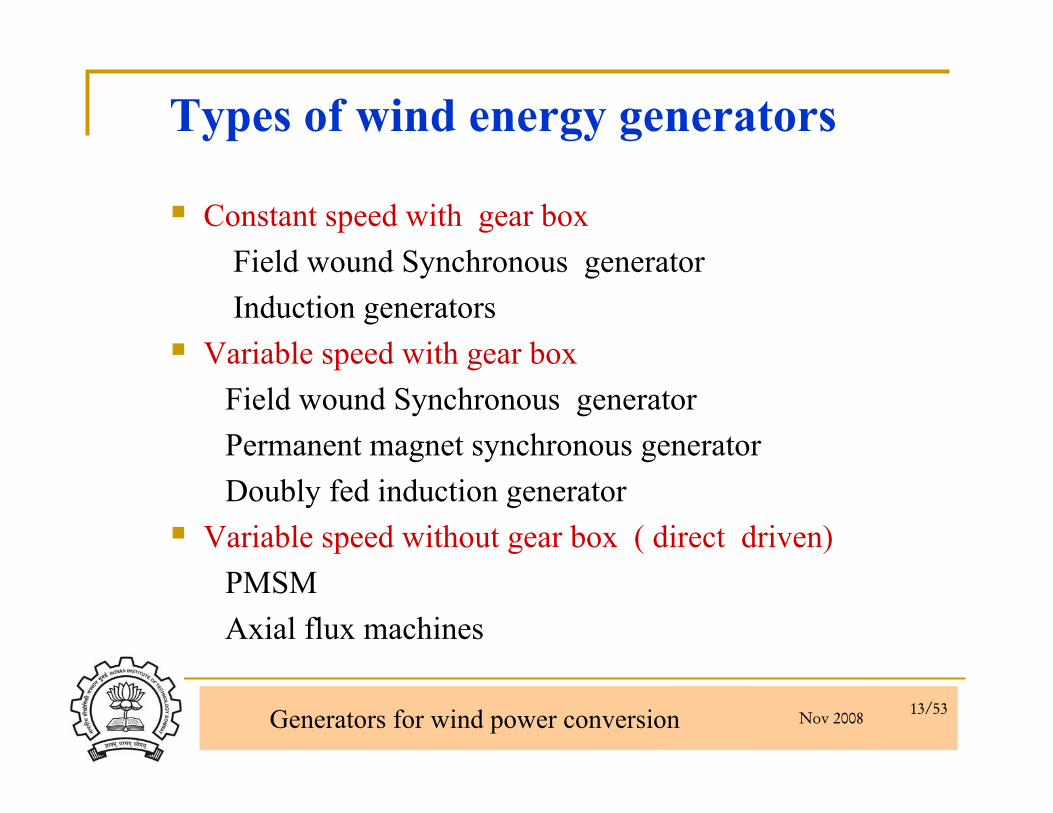
Types of wind energy generators
Constant speed with gear boxField wound Synchronous generatorInduction generators
Variable speed with gear boxField wound Synchronous generatorPermanent magnet synchronous generator Doubly fed induction generator
Variable speed without gear box ( direct driven)PMSMAxial flux machines

Nov 2008 Generators for wind power conversion 14/53
Development Path of Electrical Machines
Improvement in (efficiency x Power factor)
Increase in torque/weight or power/weight
Compact size
Better dynamic performance of motor and converter unit
High MTBF (Mean Time Between Failures)
All benefits at minimum Pay back period

Nov 2008 Generators for wind power conversion 15/53
Higher Efficiency
Loss reduction
Better quality of electrical steel for magnetic circuit (i. e low core losses)
Doubly excited:1) Permanent Magnet 2) Current flowing in a coil
Contd…

Nov 2008 Generators for wind power conversion 16/53
PM Machines – New FreedomMagnet strength proportional to depthMMF due to winding is Proportional to its areaTo reduce size and increase in efficiency, replace coil with PM
Nov 2008 Generators for wind power conversion 17/53
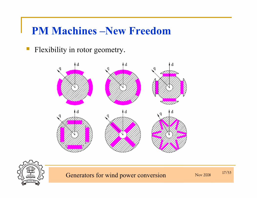
PM Machines –New FreedomFlexibility in rotor geometry.

Nov 2008 Generators for wind power conversion 18/53
Concept is not new1st by J. Henry (1831) => poor quality hard material
(1932) => ALNICO
What is NEW?
Why we were told that “rating of synchronous M/C in MW?”
Reality : Being used in ceiling fan? (≈ 40 W)
Strong contender for irrigation pumps (2-5kW)
PM Machines
Nov 2008 Generators for wind power conversion 19/53
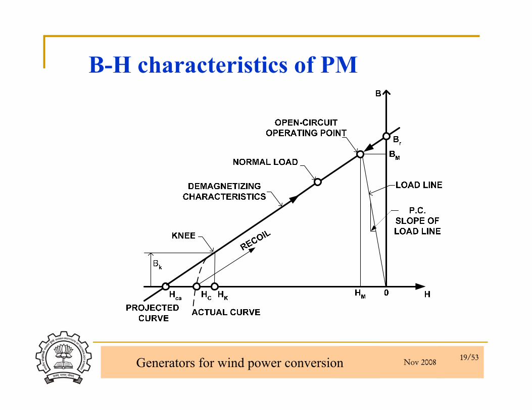
B-H characteristics of PM

Nov 2008 Generators for wind power conversion 20/53
Permanent Magnet materials
B-H Characteristics

Nov 2008 Generators for wind power conversion 21/53
Permanent Magnet Materials
PM material development
Nov 2008 Generators for wind power conversion 22/53
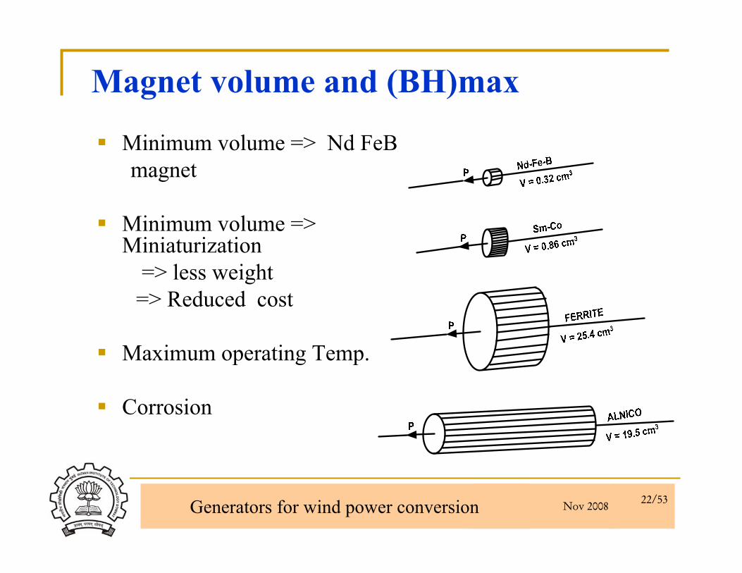
Magnet volume and (BH)max
Minimum volume => Nd FeBmagnet
Minimum volume => Miniaturization
=> less weight=> Reduced cost
Maximum operating Temp.
Corrosion
Nov 2008 Generators for wind power conversion 23/53
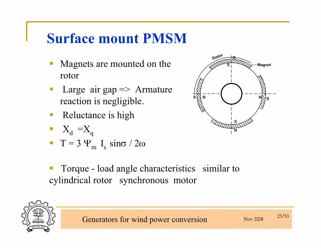
Magnets are mounted on the rotor Large air gap => Armature reaction is negligible.Reluctance is highXd =Xq
T = 3 Ψm Is sinσ / 2ω
Surface mount PMSM
Torque - load angle characteristics similar to cylindrical rotor synchronous motor
Nov 2008 Generators for wind power conversion 24/53
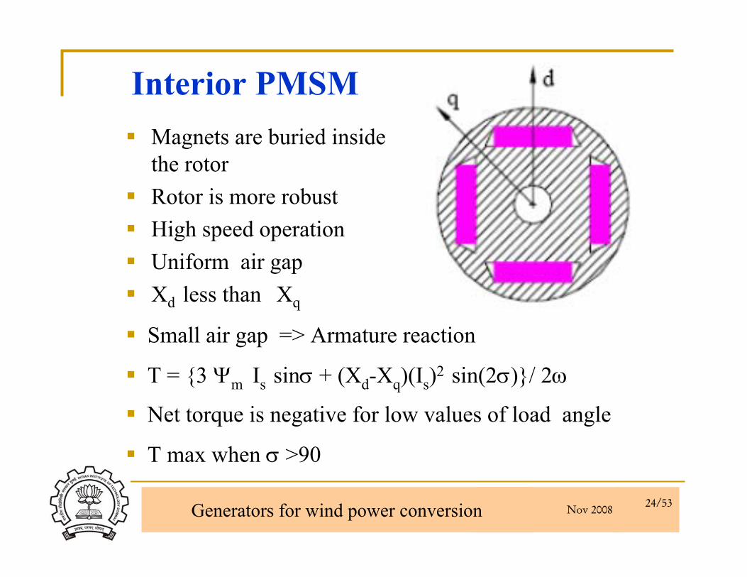
Interior PMSMMagnets are buried inside the rotorRotor is more robustHigh speed operation Uniform air gapXd less than Xq
T = {3 Ψm Is sinσ + (Xd-Xq)(Is)2 sin(2σ)}/ 2ω
Net torque is negative for low values of load angle
T max when σ >90
Small air gap => Armature reaction

Nov 2008 Generators for wind power conversion 25/53
Magnetic flux paths in IPMSM
d axis flux path
S
N
q - A
xis
N
S
S d - Axis
Rotor
Stator
Magnet
S
N
q - A
xis
N
S
S d - Axis
Rotor
Stator
Q axis flux path

Nov 2008 Generators for wind power conversion 26/53
Torque-load angle characteristic-IPMSM
0 2 0 4 0 6 0 8 0 1 0 0 1 2 0 1 4 0 1 6 0 1 8 0-2
-1
0
1
2
3
4
5
L o a d A n g le
To
rqu
e
T e 1 + T e 2
T e 1
T e 2
N o lo a d a n g le ,
Where Te1 and Te2 are magnet and reluctance torque components.The developed torque is negative=0 and δo. The pull out torque of this type of machine occurs at more than 90º.
Nov 2008 Generators for wind power conversion 27/53
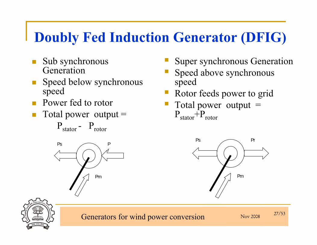
Doubly Fed Induction Generator (DFIG)Sub synchronous GenerationSpeed below synchronous speedPower fed to rotorTotal power output =
Pstator - Protor
Super synchronous GenerationSpeed above synchronous speedRotor feeds power to gridTotal power output = Pstator+Protor
Ps Pr
Pm
Ps Pr
Pm
Nov 2008 Generators for wind power conversion 28/53
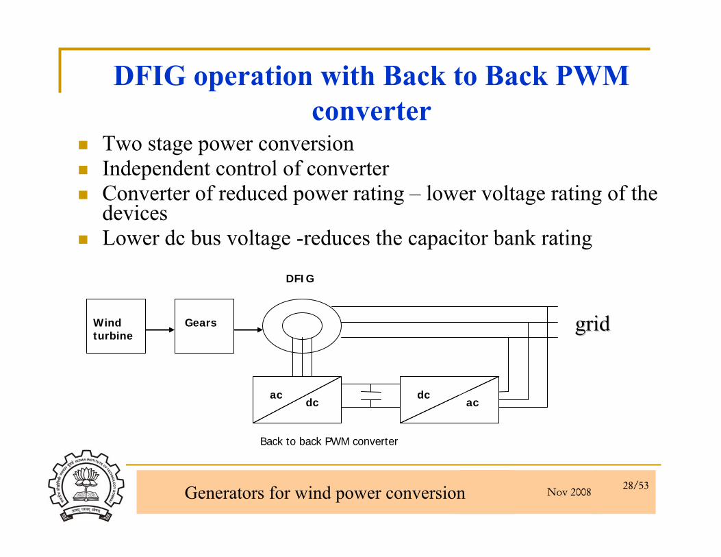
DFIG operation with Back to Back PWM converter
Two stage power conversionIndependent control of converterConverter of reduced power rating – lower voltage rating of the devicesLower dc bus voltage -reduces the capacitor bank rating
DFIG
GearsWind turbine
dcac dc
Back to back PWM converter
ac
gridgrid

Nov 2008 Generators for wind power conversion 29/53
DFIG operation with Back to Back PWM converter-control
Rotor side converter will control the active and reactive power flow in either directionLimited slip range - lower dc bus voltage hence reduces the capacitor bank ratingBy controlling the phase and amplitude of the grid side converter voltage, flow of active and reactive power can be controlled.Unity power factor operation at the grid terminals possible due to control of reactive power
Nov 2008 Generators for wind power conversion 30/53
Direct driven wind generator-without gear box
Advantages It eliminates expensive gear box and its losses.Variable speed operation allows the turbine to capturehigher energy.
DisadvantagesDirect driven generators are large in diameter.low speed generator have higher losses.
Nov 2008 Generators for wind power conversion 31/53
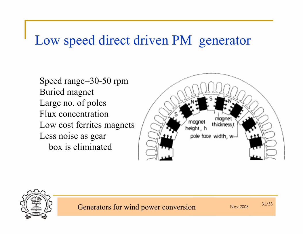
Speed range=30-50 rpmBuried magnet Large no. of polesFlux concentrationLow cost ferrites magnetsLess noise as gear
box is eliminated
Low speed direct driven PM generator

Nov 2008 Generators for wind power conversion 32/53
Electrical Machines
Axial flux Radial flux

Nov 2008 Generators for wind power conversion 33/53
Axial Flux Machine
High power density.Less winding overhang, Higher flux density
Winding with overhang Winding without overhang

Nov 2008 Generators for wind power conversion 34/53
Shaft
Rotor Stator
Strong axial magnetic attraction force between stator
and rotor
Disadvantage
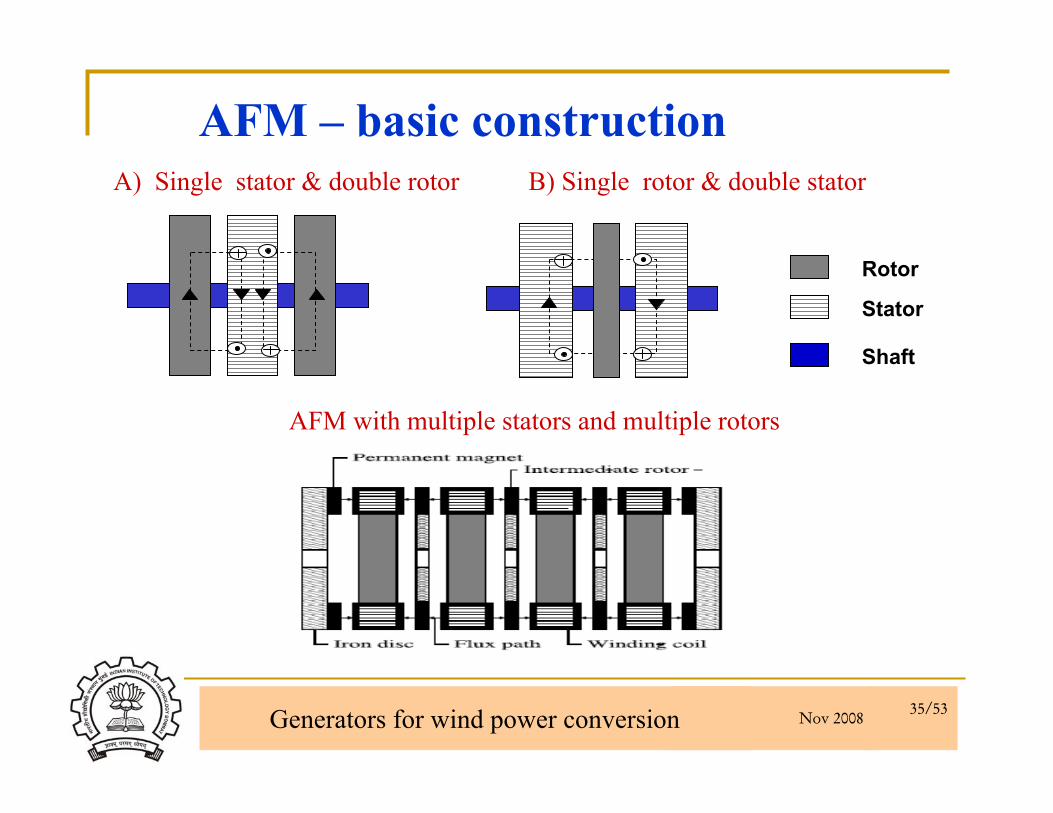
AFM – basic construction
AFM with single stator and rotor
Nov 2008 Generators for wind power conversion 35/53
`Rotor
Stator
Shaft
AFM – basic constructionA) Single stator & double rotor B) Single rotor & double stator
AFM with multiple stators and multiple rotors
Nov 2008 Generators for wind power conversion 36/53
B
Fi
F
B
i
Windings arrangement
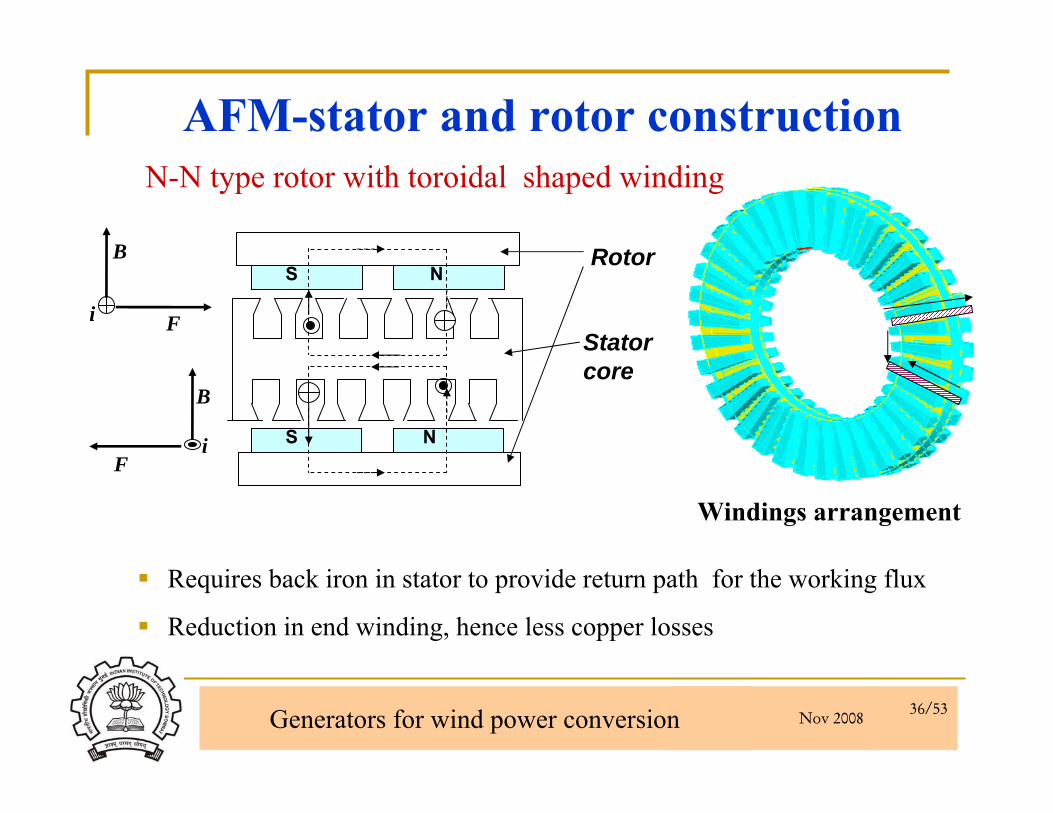
Requires back iron in stator to provide return path for the working flux
Reduction in end winding, hence less copper losses
S
S
N
NRotor
Stator core
AFM-stator and rotor constructionN-N type rotor with toroidal shaped winding
Nov 2008 Generators for wind power conversion 37/53
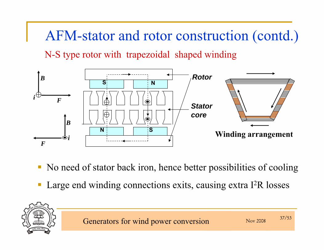
N
N
S
SB
Fi
F
B
i Winding arrangement
No need of stator back iron, hence better possibilities of cooling
Large end winding connections exits, causing extra I2R losses
Rotor
Stator core
AFM-stator and rotor construction (contd.)N-S type rotor with trapezoidal shaped winding

Nov 2008 Generators for wind power conversion 38/53
Flux lines in two rotor configuration
A) N-N type rotor
B) N-S type rotor
N
N
S S
S SN N
NN
N N N
NNS S S
SS
Nov 2008 Generators for wind power conversion 39/53
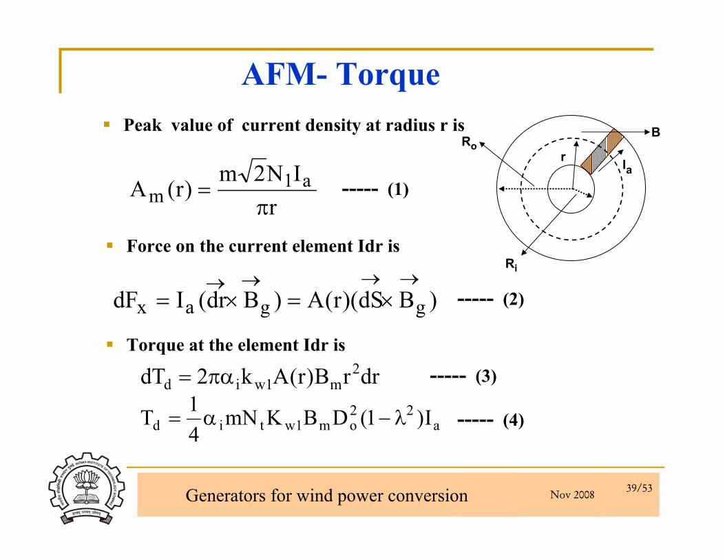
Peak value of current density at radius r is
rIN2m
)r(A a1m π
=
)BdS)(r(A)Bdr(IdF ggax→→→→
×=×=
Force on the current element Idr is
a22
om1wtid I)1(DBKmN41T λ−α=
drrB)r(Ak2dT 2m1wid πα=
Torque at the element Idr is
----- (1)
----- (2)
----- (3)
----- (4)
B
Iar
Ro
Ri
AFM- Torque

Nov 2008 Generators for wind power conversion 40/53
Contd…Selection of the outer diameter
3ms1w
2out
out cosABnkP.60D
φηλπε
= 3s
out n1 D α
(Taking other parameters to be constant)
So less speed requirement Much more increase in outer diameterMore slots can be made to achieve higher pole pairs (lower speed) on large diameter)
Optimization goalKw1, by the proper selection of winding configurationε = Ef/V1,depend on winding inductanceBm by proper selection of magnet shape and span
Nov 2008 Generators for wind power conversion 41/53
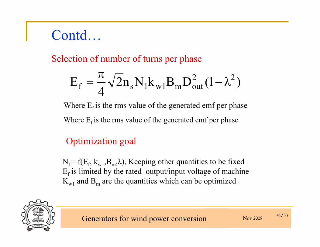
)1(DBkNn24
E 22outm1w1sf λ−
π=
Where Ef is the rms value of the generated emf per phase
Where Ef is the rms value of the generated emf per phase
N1= f(Ef, kw1,Bm,λ), Keeping other quantities to be fixed Ef is limited by the rated output/input voltage of machineKw1 and Bm are the quantities which can be optimized
Contd…Selection of number of turns per phase
Optimization goal
Nov 2008 Generators for wind power conversion 42/53
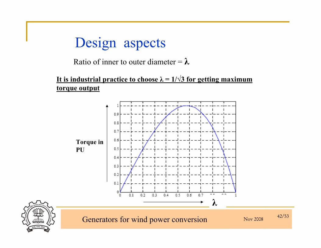
Design aspectsRatio of inner to outer diameter = λ
It is industrial practice to choose λ = 1/√3 for getting maximum torque output
λ
Torque in PU
Nov 2008 Generators for wind power conversion 43/53
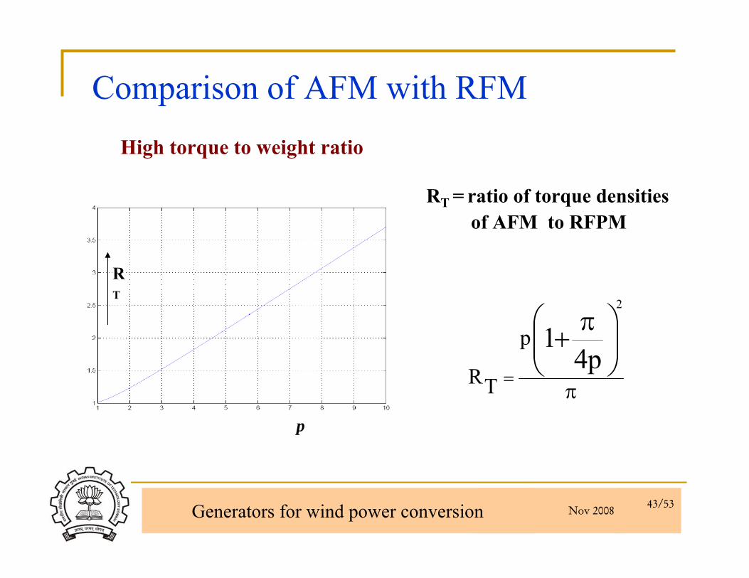
Comparison of AFM with RFMHigh torque to weight ratio
RT = ratio of torque densitiesof AFM to RFPM
p
RT
π
⎟⎟⎠
⎞⎜⎜⎝
⎛ π+=
p41
2
p
TR
Nov 2008 Generators for wind power conversion 44/53
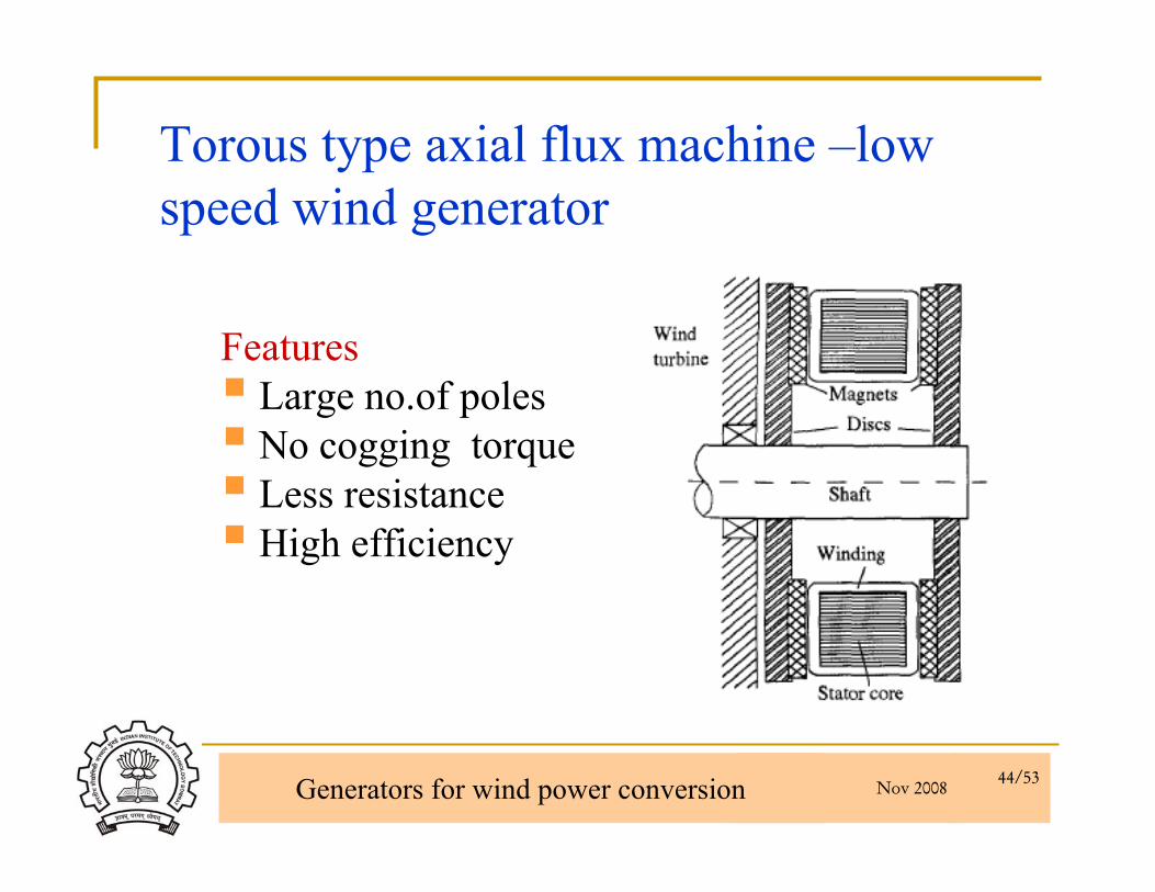
Torous type axial flux machine –low speed wind generator
FeaturesLarge no.of polesNo cogging torqueLess resistanceHigh efficiency

Nov 2008 Generators for wind power conversion 45/53
Wind Turbine Generator (16 pole configuration)
1 kW, 375 rpm, 110 V, 50 Hz
For direct driven wind generator.

Nov 2008 Generators for wind power conversion 46/53
Doubly salient PM Machines- Three Phase Flux Reversal Machine
Magnets and winding are stationary6/8 pole configurationnr = ns (npp+1/3)f =(n × nr)/60Equivalent to 16 pole PMSM PM required are 12Flux pattern of 2 poles
Nov 2008 Generators for wind power conversion 47/53
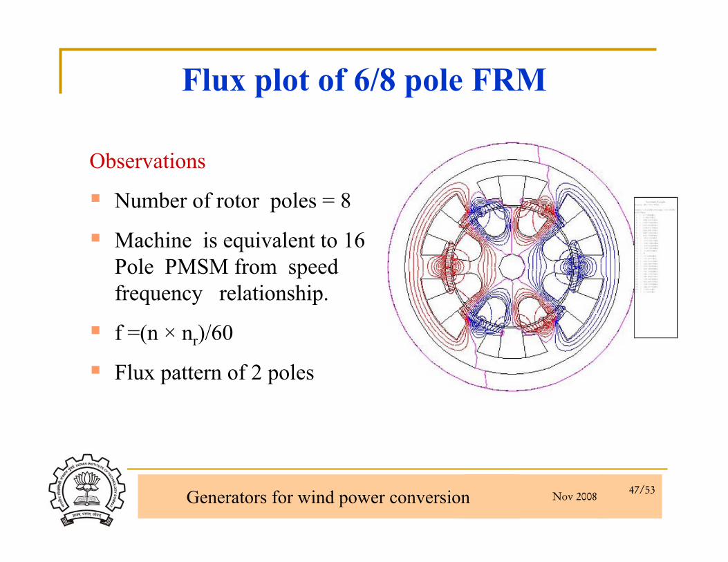
Flux plot of 6/8 pole FRM
Observations
Number of rotor poles = 8
Machine is equivalent to 16 Pole PMSM from speed frequency relationship.
f =(n × nr)/60
Flux pattern of 2 poles
Nov 2008 Generators for wind power conversion 48/53
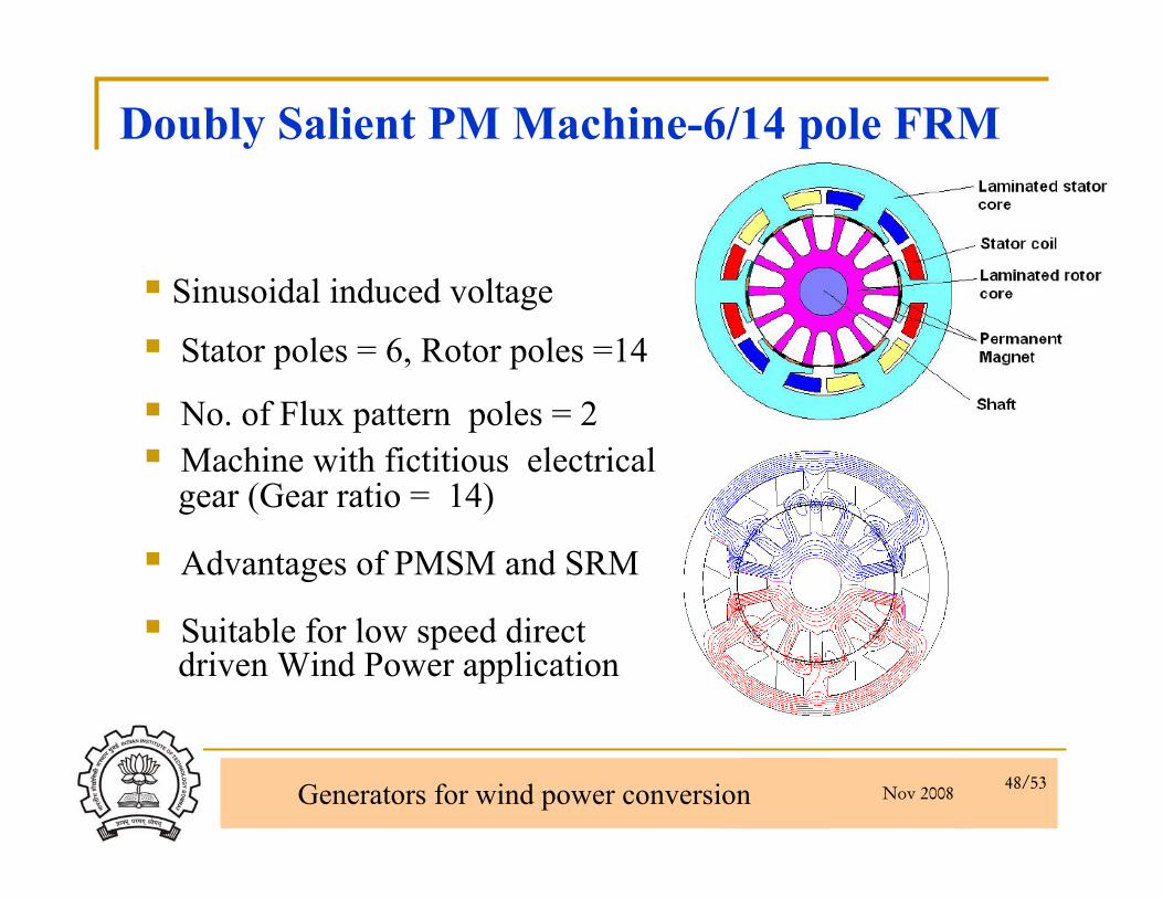
Doubly Salient PM Machine-6/14 pole FRM
Sinusoidal induced voltage
Stator poles = 6, Rotor poles =14
No. of Flux pattern poles = 2Machine with fictitious electricalgear (Gear ratio = 14)
Advantages of PMSM and SRM
Suitable for low speed directdriven Wind Power application

Nov 2008 Generators for wind power conversion 49/53
Fictitious Electrical GearFRM can be analyzed as PMSM with gear
Flux pattern speed and rotor speed is different
Gear ratio is defined as ratio of flux pattern speed to rotor speed
Nov 2008 Generators for wind power conversion 50/53
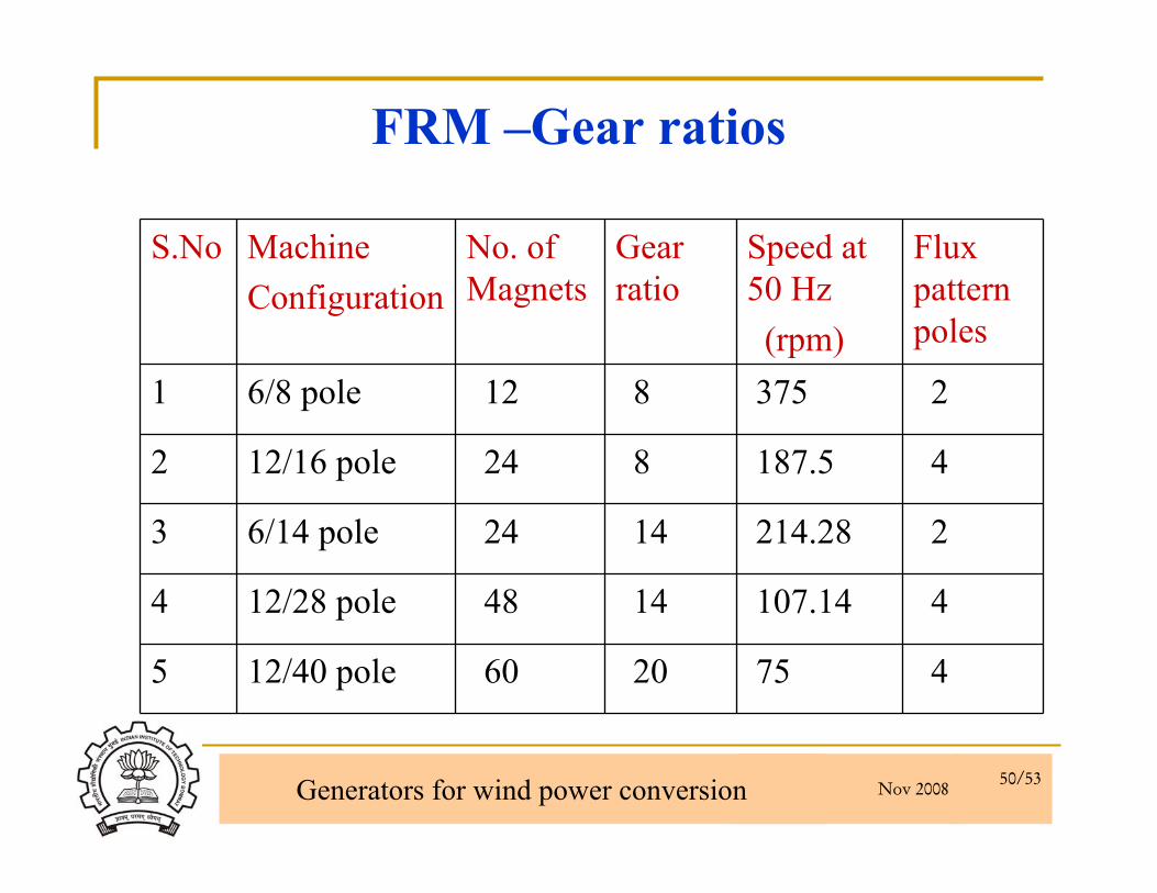
S.No MachineConfiguration
No. of Magnets
Gear ratio
Speed at 50 Hz(rpm)
Flux pattern poles
1 6/8 pole 12 8 375 2
2 12/16 pole 24 8 187.5 4
3 6/14 pole 24 14 214.28 2
4 12/28 pole 48 14 107.14 4
5 12/40 pole 60 20 75 4
FRM –Gear ratios
Nov 2008 Generators for wind power conversion 51/53
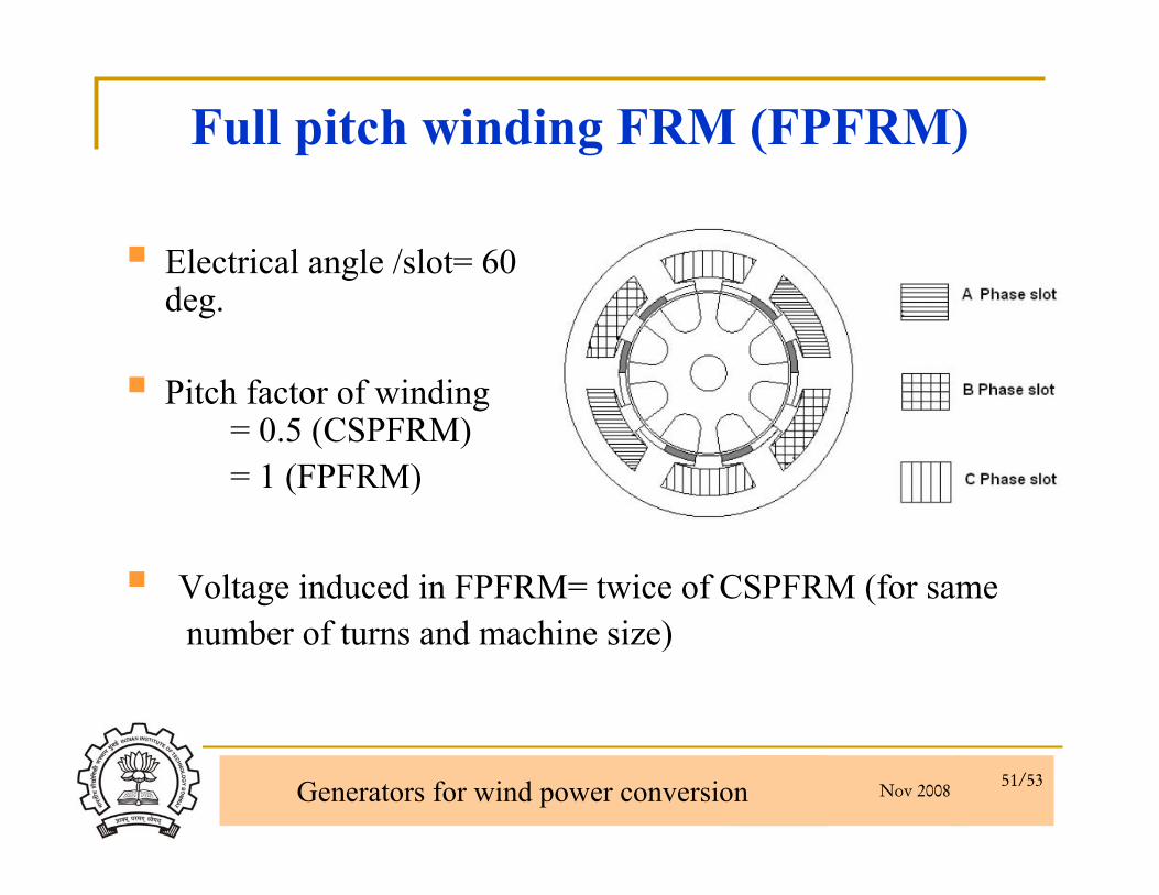
Full pitch winding FRM (FPFRM)
Electrical angle /slot= 60 deg.
Pitch factor of winding = 0.5 (CSPFRM)= 1 (FPFRM)
Voltage induced in FPFRM= twice of CSPFRM (for samenumber of turns and machine size)
Nov 2008 Generators for wind power conversion 52/53
Conclusion
Direct driven variable speed wind energyconversion systems are more efficient and are possible using PM machines.
For low speed operation axial flux machinesare preferred
FRM topology is suitable for low speed lowpower application
Nov 2008 Generators for wind power conversion 53/53