GENERATOR ROTECTION OVERVIEW · WSU HORS 2018 Generator Protection TheoryGenerator Protection. Use...
150
GENERATOR PROTECTION OVERVIEW
Transcript of GENERATOR ROTECTION OVERVIEW · WSU HORS 2018 Generator Protection TheoryGenerator Protection. Use...

GENERATOR PROTECTIONOVERVIEW

n
Presenter Contact Info
Wayne is the top strategist for delivering innovative technology messagesto the Electric Power Industry through technical forums and industrystandard development.
Wayne HartmannSenior VP, Customer ExcellenceBeckwith Electric Company
[email protected]‐238‐3844
Before joining Beckwith Electric, performed in Application, Sales and Marketing Managementcapacities at PowerSecure, General Electric, Siemens Power T&D and Alstom T&D.
Provides training and mentoring to Beckwith Electric personnel in Sales, Marketing, CreativeTechnical Solutions and Engineering.
Key contributor to product ideation and holds a leadership role in the development of coursestructure and presentation materials for annual and regional Protection & Control Seminars.
Senior Member of IEEE, serving as a Main Committee Member of the Power System Relayingand Control Committee for over 25 years. Chair Emeritus of the IEEE PSRCC Rotating Machinery Subcommittee (’07‐’10). Contributed to numerous IEEE Standards, Guides, Reports, Tutorials and Transactions, delivered Tutorials IEEE
Conferences, and authored and presented numerous technical papers at key industry conferences.
Contributed to McGraw‐Hill's “Standard Handbook of Power Plant Engineering.”2

Unit Connected,High Z Grounded
3

Generator Construction:Simple Bock Diagram
G
Prime Mover(Mechanical Input)
Three-PhaseElectricalOutput
iaibic
DC Field Source
Generator Protection
4
WSU HORS 2018 Generator Protection Theory

Applying Mechanical Input
1. Reciprocating Engines2. Hydroelectric3. Gas Turbines (GTs, CGTs)4. Steam Turbines (STs)
1
42
3
Generator Protection
5
WSU HORS 2018 Generator Protection Theory

Applying FieldStatic Exciter
• DC is induced in the rotor• AC is induced in the stator
Generator Protection
6
WSU HORS 2018 Generator Protection Theory

Cylindrical rotor seen in Recips, GTs and STs Salient pole rotor seen in Hydros
More poles to obtain nominal frequency at low RPM Eq: f= [RPM/60] * [P/2] = [RPM * P] / 120
Cylindrical (Round) Salient
Generator Protection
Rotor Styles
7
WSU HORS 2018 Generator Protection Theory

Cylindrical Rotor & Stator
Generator Protection
8
WSU HORS 2018 Generator Protection Theory

Salient Pole Rotor & Stator
Generator Protection
9
WSU HORS 2018 Generator Protection Theory

Generator Behavior During Short Circuits
Generator Protection
10
WSU HORS 2018 Generator Protection Theory

Generator Short-Circuit Current Decay
Generator Protection
11
WSU HORS 2018 Generator Protection Theory

Effect of DC OffsetsThree-Phase Fault
Cur
rent
Cur
rent
Cur
rent
Generator Protection
12
WSU HORS 2018 Generator Protection Theory

Grounding Techniques
Why Ground?• Improved safety by allowing detection of faulted
equipment• Stop transient overvoltages
• Notorious in ungrounded systems• Ability to detect a ground fault before a multiphase
to ground fault evolves• If impedance is introduced, limit ground fault
current and associated damage faults • Provide ground source for other system protection
(other zones supplied from generator)
Generator Protection
13
WSU HORS 2018 Generator Protection Theory

Types of Generator Grounding
Low Impedance• Good ground source
• The lower the R, the better the ground source
• The lower the R, the more damage to the generator on internal ground fault
• Can get expensive as resistor voltage rating goes up
• Generator will be damaged on internal ground fault• Ground fault current typically 200-
400 A
R
System
GroundingResistor
Generator Protection
14
WSU HORS 2018 Generator Protection Theory

Types of Generator Grounding
High Impedance With delta/wye GSU, creates “unit
connection” System ground source obtained from
GSU Uses principle of reflected impedance Eq: RNGR = RR / [Vpri/Vsec]2
RNGR = Neutral Grounding Resistor Resistance
RR = Reflected Resistance
Ground fault current typically <=10A
System
R
RNGR
RR
GSUTransformer
Neutral Grounding
Transformer
Generator Protection
15
WSU HORS 2018 Generator Protection Theory

Hybrid GroundConverts from low-Z
to high-Z for internal generator fault
Hybrid Impedance Grounding• Has advantages of Low-Z and High-Z
ground• Normal Operation
• Low-Z grounded machine provides ground source for other zones under normal conditions
• 51G acts as back up protection for uncleared system ground faults
• 51G is too slow to protect generator for internal fault
Ground Fault in Machine• Detected by the 87GD element• The Low-Z ground path is opened by a
vacuum switch• Only High-Z ground path is then available
• The High-Z ground path limits fault current to approximately 10A (stops generator damage)
Generator Protection
Types of Generator Grounding
16
WSU HORS 2018 Generator Protection Theory

Hybrid GroundConverts from low-Z
to high-Z for internal generator fault
Generator Protection
Types of Generator Grounding
17
WSU HORS 2018 Generator Protection Theory

Types of Generator Ground Fault Damage
Following pictures show stator damage after an internal ground fault
This generator was high impedance grounded, with the fault current less than 10A
Some iron burning occurred, but the damage was repairable
With low impedance grounded machines the damage is severe
Generator Protection
18
WSU HORS 2018 Generator Protection Theory

Generator Protection
Stator Ground Fault Damage
19
WSU HORS 2018 Generator Protection Theory

Generator Protection
Stator Ground Fault Damage
20
WSU HORS 2018 Generator Protection Theory

Generator Protection
Stator Ground Fault Damage
21
WSU HORS 2018 Generator Protection Theory

Generator Protection
Stator Ground Fault Damage
22
WSU HORS 2018 Generator Protection Theory

Bus or Direct Connected (typically Low Z)
- Directly connected to bus
- Likely in industrial, commercial, and isolated systems
- Simple, inexpensive
Types of Generator Connections
Generator Protection
23
WSU HORS 2018 Generator Protection Theory

Multiple Direct or Bus Connected(No/Low Z/High Z)
- Directly connected to bus
- Likely in industrial, commercial, and isolated systems
- Simple
- May have problems with circulating current
Use of single grounded machine can help
- Adds complexity to discriminate ground fault source
BUS
Same type of grounding used on 1 or mutiple generators
Generator Protection
Types of Generator Connections
24
WSU HORS 2018 Generator Protection Theory
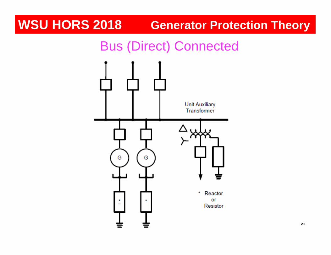
Generator Protection
Bus (Direct) Connected
25
WSU HORS 2018 Generator Protection Theory

Unit Connected (High Z)
- Generator has dedicated unit transformer
- Generator has dedicated ground transformer
- Likely in large industrial and utility systems
- 100% stator ground fault protection availableBUS
Generator Protection
Types of Generator Connections
26
WSU HORS 2018 Generator Protection Theory

Multiple Bus (High Z), 1 or Multiple Generators- Connected through one unit xfmr- Likely in large industrial and utility systems- No circulating current issue- Adds complexity to discriminate ground fault source
Special CTs needed for sensitivity, and directional ground overcurrent elements
Generator Protection
Types of Generator Connections
27
WSU HORS 2018 Generator Protection Theory

Generator Protection
Unit Connected
28
WSU HORS 2018 Generator Protection Theory

Internal and External Short Circuits
"Wild" Power System
Exciter
StatorGround
StatorPhase
SystemGround
SystemPhase
Generator Protection Overview
Generator Protection
29
WSU HORS 2018 Generator Protection Theory

Abnormal Operating Conditions
"Wild" Power System
Exciter
Loss of FieldLoss of Field
Overexcitation
Overexcitation
Overexcitation
OpenCircuits
Loss of Synchronism
InadvertentEnergizing,Pole Flashover
AbnormalFrequency
AbnormalFrequency
Breaker FailureReverse Power
Generator Protection OverviewGenerator Protection
30
WSU HORS 2018 Generator Protection Theory
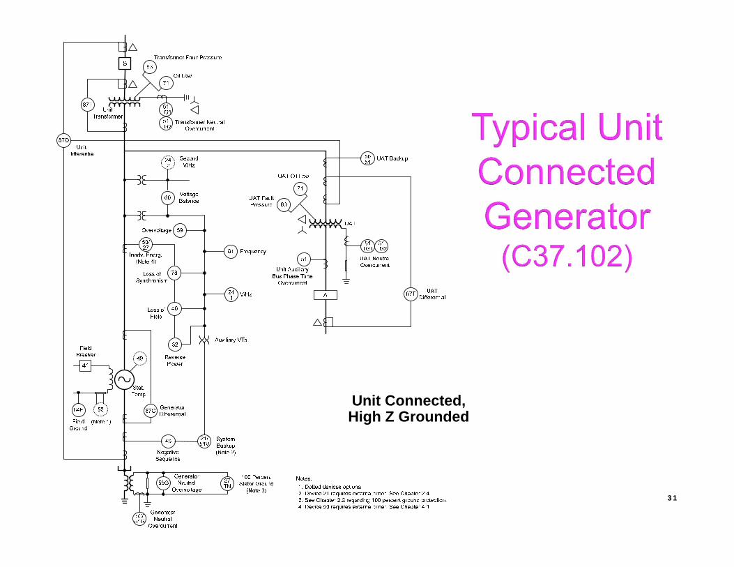
Unit Connected,High Z Grounded
31

95% stator ground fault provided by 59GTuned to the fundamental frequency• Must work properly from 10 to 80 Hz to provide
protection during startup
Additional coverage near neutral (last 5%) provided by:• 27TN: 3rd harmonic undervoltage• 59D: Ratio of 3rd harmonic at terminal and neutral
ends of winding
Full 100% stator coverage by 64S• Use of sub-harmonic injection• May be used when generator is off-line• Immune to changes in loading (MW, MVAR)
Stator Ground Fault-High Z Grounded Machines
Generator Protection
32
WSU HORS 2018 Generator Protection Theory

Generator Protection
High impedance ground limits ground fault current to about 10A• Limits damage on internal ground fault
Conventional neutral overvoltage relay provides 90-95% stator coverage
Last 5-10% near neutral not covered
Undetected grounds in this region bypass grounding transformer, solidly grounding the machine!
Stator Ground Fault (59G)
33
59G
WSU HORS 2018 Generator Protection Theory

Fault Position
Volta
ge a
t Neu
tral
(60
Hz)
0% 50% 100%0
0.5pu
1.0pu
N T
59G Element
Generator Protection
Neutral grounding transformer (NGT) ratio selected that provides 120 to 240V for ground fault at machine terminals Max L-G volts =13.8kV / 1.73 = 7995V Max NGT volts sec. = 7995V / 120V = 66.39 VTR
34
59G
WSU HORS 2018 Generator Protection Theory

59G System Ground Fault Issue
GSU provides capacitive coupling for system ground faults into generator zone
Use two levels of 59G with short and long time delays for selectivity
Cannot detect ground faults at/near the neutral (very important) 35
Generator ProtectionWSU HORS 2018 Generator Protection Theory

Multiple 59G Element Application
59G-1, set in this example to 5%, may sense capacitance coupled out-of-zone ground fault Long time delay
• 59G-2, set in this example to 15%, is set above capacitance coupled out-of-zone ground fault– Short time delay
Tim
e (c
ycle
s)
36
Generator ProtectionWSU HORS 2018 Generator Protection Theory

Use of Symmetrical Component Quantitiesto Supervise 59G Tripping Speed
A ground fault in the generator zone produces primarily zero sequence voltage• Negligible V2, I2 or I0
A fault in the VT secondary or system (GSU coupled) generates negative sequence quantities in addition to zero sequence voltage
The I2 method may be employed to control the 59G for system ground faults
The V2/V0 method may be employed to control the 59G for system and VT secondary ground faults
37
Generator ProtectionWSU HORS 2018 Generator Protection Theory

Use of I2 to Supervise 59G Tripping Speed
38
Generator Protection
I2
SettingTime
SettingTime
Block
Block
[A]
[B]
NOTES:[A] 59G-1 is set sensitive and fast, using I2 supervision to check for external ground faults and control (block) the element for external ground faults[B] 59G-2 is set less sensitive and slower, therefore it will not operate for external ground faults.
WSU HORS 2018 Generator Protection Theory

Use of V2 /V0 to Supervise 59G Tripping Speed
39
Generator Protection
[C] V2 > 0.05 pu
[D] V0 < 0.07 pu
60FL Asserts [A]
SettingTime
SettingTime
NOTES:[A] 59G-1 is set sensitive and fast, using V2 and V0 supervision to check for external ground faults and control (block) the element for external ground faults[B] 59G-2 is set less sensitive and slower, therefore it will not operate for external ground faults.[C] V2 derived from 3Y phase VTs[D] V0 derived from 3Y phase VTs
Block
Block
[B]
OR
WSU HORS 2018 Generator Protection Theory

59G – Generator Neutral Overvoltage: Three setpoints
1st level set sensitive to cover down to 5% of stator• Long delay to coordinate with close-in system ground faults
capacitively coupled across GSU
2nd level set higher than the capacitively coupled voltage so coordination from system ground faults is not necessary• Allows higher speed tripping• Only need to coordinate with PT fuses
3rd level may be set to initiate waveform captureand not trip, set as intermittent arcing fault protection
59G Element
Generator Protection
40
WSU HORS 2018 Generator Protection Theory

Intermittent Arcing Ground Faults
41
Generator Protection
Can be very destructive, especially at neutral At neutral, even though AC current is very low, arcing fault
develops a high voltage DC transient If enough arcs occur in a short time, destructive insulation
damage can occur Conventional time delayed ground fault protection cannot
protect for these events
Burned away copper of a fractured connection ring
Premature Failure of Modern Generators, Clyde V. Maughan
Side of a bar deeply damagedby vibration sparking
WSU HORS 2018 Generator Protection Theory

Intermittent Arcing Ground Fault
42
Generator ProtectionWSU HORS 2018 Generator Protection Theory

Intermittent Arcing Fault Timer Logic
Stallable Trip Timer: Times Out to TripIntegrating Reset Time: Delays Reset for Interval
43
Generator ProtectionWSU HORS 2018 Generator Protection Theory

Intermittent Arcing Ground Fault
44
Generator Protection
Arcing and Trip
WSU HORS 2018 Generator Protection Theory

45
Generator Protection
Intermittent Arcing Ground Fault
Arcing and Reset (No Trip)
WSU HORS 2018 Generator Protection Theory

Intermittent Arcing Ground Fault Turned Multiphase
46
Generator ProtectionWSU HORS 2018 Generator Protection Theory

Why Do We Care About Faults Near Neutral?
A fault at or near the neutral shunts the high resistance that saves the stator from large currents with an internal ground fault
A generator operating with an undetected ground fault near the neutral is a accident waiting to happen
We can use 3rd Harmonic or Injection Techniques for complete (100%) coverage
47
Generator ProtectionGenerator ProtectionWSU HORS 2018 Generator Protection Theory

• Develops in stator due to imperfections in winding and system connections
• Unpredictable amount requiring field observation at various operating conditions
• Also dependent on pitch of the windings, which a method to define the way stator windings placed in the stator slots
Third-Harmonic Rotor Flux
Rotor MMF
Generator Protection
48
Generator ProtectionGenerator ProtectionGenerator ProtectionWSU HORS 2018 Generator Protection Theory

R
C
3I3h
I3h A, B, C
Generator winding and terminal capacitances (C) provide path for the third-harmonic stator current via grounding resistor
This can be applied in protection schemes for enhanced ground fault protection coverage
Using Third Harmonic in Generators
Generator Protection
49
Generator ProtectionGenerator ProtectionGenerator ProtectionWSU HORS 2018 Generator Protection Theory

Generator Capacitance and 3rd Harmonics
3rd harmonics are produced by some generators Amount typically small
• Lumped capacitance on each stator end is CS/2. CT is added at terminal end due to surge caps and
isophase bus Effect is 3rd harmonic null point is shifted toward
terminal end and not balanced50
Generator ProtectionGenerator ProtectionGenerator ProtectionGenerator ProtectionWSU HORS 2018 Generator Protection Theory

3rd harmonic may be present in terminal and neutral ends
Useful for ground fault detection near neutral• If 3rd harmonic goes
away, conclude a ground fault near neutral
3rd harmonic varies with loading
3rd Harmonic in Generators
Generator Protection
51
Generator ProtectionGenerator ProtectionGenerator ProtectionWSU HORS 2018 Generator Protection Theory

Provides 0-15% stator winding coverage (typ.)
Tuned to 3rd harmonic frequency
Provides two levels of setpoints
Supervisions for increased security under various loading conditions: Any or All May be Applied Simultaneously
Phase Overvoltage Supervision Underpower Block Forward & Reverse Under VAr Block; Lead & Lag Power Factor Block; Lead & Lag Definable Power Band Block
27TN – 3rd Harmonic Neutral Undervoltage
Generator Protection
Undervoltage/No Voltage Block Varies with load May vary with power flow direction May vary with level May vary with lead and lag May be gaps in output
Loading/operating variables may be Sync Condenser, VAr Sink, Pumped Storage, CT Starting, Power Output Reduction
52
Generator ProtectionGenerator ProtectionGenerator ProtectionWSU HORS 2018 Generator Protection Theory

3rd harmonic values tend to increase with power and VAr loading Fault near neutral causes 3rd harmonic voltage at neutral to go to zero volts
3rd Harmonic in Generators: Typical 3rd Harmonic Values
Generator Protection
53
Generator ProtectionGenerator ProtectionGenerator ProtectionWSU HORS 2018 Generator Protection Theory

Example 3rd Harmonic Plot: Effects of MW and MVAR Loading
Generator Protection
54
Generator ProtectionGenerator ProtectionGenerator ProtectionWSU HORS 2018 Generator Protection Theory

Third-Harmonic Undervoltage Ground-Fault Protection Scheme
100% Stator Ground Fault (59G/27TN)
Generator Protection
59G
0‐15% Coverage
27TN
59
59G
27TN
59AND
OR TRIP
Power Supervisions SatisfiedPower Supervisions Satisfied
55
Generator ProtectionGenerator ProtectionGenerator ProtectionWSU HORS 2018 Generator Protection Theory

Overlap of Third Harmonic (27TN) with 59G Relay
100% Stator Ground Fault (59G/27TN)
Generator Protection
0
0.5
1.0
-10
+10
0
59G27TN
3rd Harmonic Voltage profile in
winding
Vfund profile in winding
27TN pickup59N pickup
56
Generator ProtectionGenerator ProtectionGenerator ProtectionWSU HORS 2018 Generator Protection Theory

Examines 3rd harmonic at line and neutral ends of generator
Provides 0-15% and 85-100% stator winding coverage (typ.)
Does not have a security issue with loading, as can a 27TN
- May be less reliable than 27TN (not enough difference to trip)
“Blind spot” at mid-winding protected by 59G
Needs wye PTs; cannot use delta PTs
59D – 3rd Harmonic Ratio Voltage
Generator Protection
57
Generator ProtectionGenerator ProtectionGenerator ProtectionWSU HORS 2018 Generator Protection Theory

59D – 3rd Harmonic Ratio Voltage
Employs comparison of 3rd harmonic voltages at terminal and neutral ends
These voltages are fairly close to each other One goes very low if a ground fault occurs at either end of the
winding
59G
0‐15% Coverage
59D 3V0VN
85‐100% Coverage
Generator Protection
58
Generator ProtectionGenerator ProtectionGenerator ProtectionWSU HORS 2018 Generator Protection Theory

Stator Ground Faults: 59N, 27TN, 59D
Generator Protection
59
Generator ProtectionGenerator ProtectionGenerator ProtectionWSU HORS 2018 Generator Protection Theory

Subharmonic Injection: 64S
20Hz injected into grounding transformer secondary circuit
Rise in real component of injected current suggests resistive ground fault
Ignores capacitivecurrent due to isophase bus and surge caps Uses it for self-diagnostic
and system integrity
Coupling Filter VoltageInjector
Measurements
I
Natural Capacitance
Notes:Subharmonic injection frequency = 20 HzCoupling filter tuned for subharmonic frequencyMeasurement inputs tuned to respond to subharmonic frequency
V
VoltageInjector
20Hz
60
Generator ProtectionGenerator ProtectionGenerator ProtectionWSU HORS 2018 Generator Protection Theory

Generator Protection
Injects subharmonic frequency into generator neutral• Does not rely on third harmonic signature of
generator
Frequency independent• Indifferent to generator’s operating frequency
Provides full coverage protection Provides on and offline protection, prevents
serious damage upon application of excitation if ground fault exists
64S: Stator Ground Faults – Subharmonic Injection
61
Generator ProtectionGenerator ProtectionWSU HORS 2018 Generator Protection Theory

Stator Ground Faults: High Z Element Coverage
Generator Protection
62
Generator ProtectionGenerator ProtectionGenerator ProtectionWSU HORS 2018 Generator Protection Theory

Brushed and “Brushless” Excitation
Brushed
“Brushless”
63
A
B
C
SET
ROTOR
DC
STATOR
STATOR
EXCITER AVR
Grounding Brush
PowerCommutation
Brushes
Generator ProtectionGenerator ProtectionGenerator ProtectionWSU HORS 2018 Generator Protection Theory

Field/Rotor Ground Fault
Traditional field/rotor circuit ground fault protection schemes employ DC voltage detection Schemes based on DC principles are subject to
security issues during field forcing, other sudden shifts in field current and system transients
64
Generator ProtectionGenerator ProtectionGenerator ProtectionWSU HORS 2018 Generator Protection Theory

DC-Based 64F
65
Generator ProtectionGenerator ProtectionGenerator ProtectionWSU HORS 2018 Generator Protection Theory

Field/Rotor Ground Fault (64F)
To mitigate the security issues of traditional DC-based rotor ground fault protection schemes, AC injection based protection may be used AC injection-based protection ignores the
effects of sudden DC current changes in the field/rotor circuits and attendant DC scheme security issues
66
Generator ProtectionGenerator ProtectionGenerator ProtectionWSU HORS 2018 Generator Protection Theory

Advanced AC Injection Method
Exciter
Field
+
ExciterBreaker
–
CouplingNetwork
ProtectiveRelay
Signal Measurement& Processing
Square Wave Generator
67
Generator ProtectionGenerator ProtectionGenerator ProtectionWSU HORS 2018 Generator Protection Theory

Advanced AC Injection Method: Advantages
Scheme is secure against the effects of DC transients in the field/rotor circuit DC systems are prone to false alarms and false trips, so they
sometimes are ignored or rendered inoperative, placing the generator at risk
The AC system offers greater security so this important protection is not ignored or rendered inoperative
Scheme can detect a rise in impedance which is characteristic of grounding brush lift-off In brushless systems, the measurement brush may be
periodically connected for short time intervals The brush lift-off function must be blocked during the time
interval the measurement brush is disconnected 68
Generator ProtectionGenerator ProtectionGenerator ProtectionWSU HORS 2018 Generator Protection Theory

Rotor Ground Fault Measurement
PROCESSOR
SQUAREWAVEGENERATOR
PROTECTIONRELAY(M-3425A)
FIELD GROUNDDETECTION
SIGNALMEASUREMENTCIRCUIT
37
VOUT
36
35
Measurement Point Time
Vf
VRVOUT
M-3921COUPLING NETWORK
GEN.ROTOR
MachineFrameGround
+
-RR
RC
C
Vf
ShaftGround BrushRf Cf,
Generator Protection
Plan a shutdown to determine why impedance is lowering, versus an eventual unplanned trip!
When resistive fault develops, Vf goes down
69
Generator ProtectionGenerator ProtectionGenerator ProtectionWSU HORS 2018 Generator Protection Theory

Commutation brush lift-off will lead to:- Arcing- Tripping on loss-of-field
Grounding brush lift-off can lead to:- Stray currents that cause bearing pitting
Grounding Brush
CommutationBrush
64B: Brush Lift Off
Generator Protection
70
Generator ProtectionGenerator ProtectionGenerator ProtectionWSU HORS 2018 Generator Protection Theory

Grounding Brush
As brushes lift-off, the sawtooth wave’s return signal slope gets less rounded, which is detected as a rise in voltage
CommutationBrush
64B: Brush Lift Off
Generator Protection
71
Generator ProtectionGenerator ProtectionGenerator ProtectionWSU HORS 2018 Generator Protection Theory

Brush Lift-Off Measurement
PROCESSOR
SQUAREWAVEGENERATOR
PROTECTIONRELAY(M-3425A)
FIELD GROUNDDETECTION
SIGNALMEASUREMENTCIRCUIT
37
VOUT
Vf SignalVALARM
VNORMAL
Brush Lift-Off Voltage
Measurement Point
VNORMAL = Normal Voltage forHealthy Brush Contact
VALARM = Alarm Voltage when BrushResistance Increases dueto poor contact
Time
36
35
M-3921COUPLING NETWORK
GEN.ROTOR
MachineFrameGround
+
-RR
RC
C
Vf
ShaftGround BrushRf Cf,
Generator Protection
72
When brush lifts off, Vf goes up
Generator ProtectionGenerator ProtectionGenerator ProtectionWSU HORS 2018 Generator Protection Theory
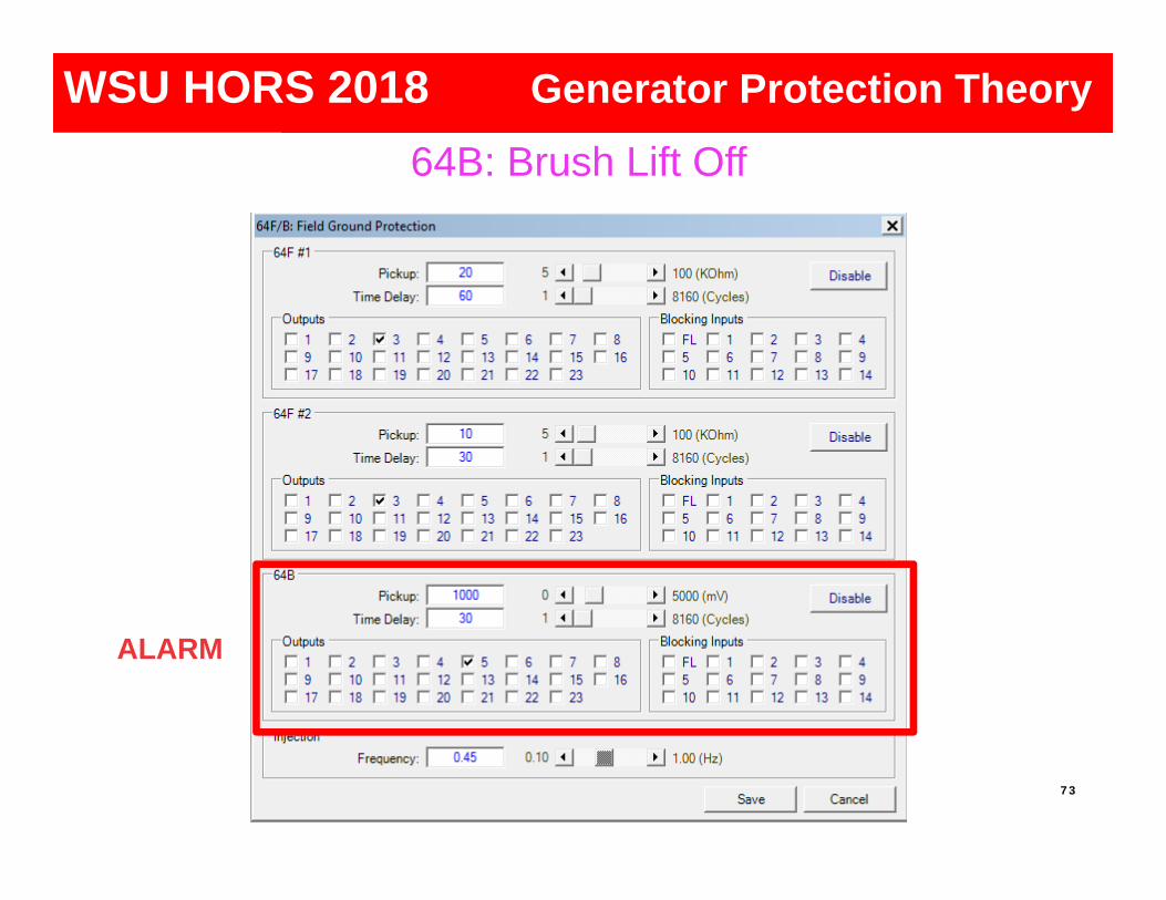
64B: Brush Lift Off
Generator Protection
73
ALARM
Generator ProtectionGenerator ProtectionGenerator ProtectionWSU HORS 2018 Generator Protection Theory

64F/B- It is possible to apply two
systems and have redundancy
- The switch system is initiated by manual means or by monitoring relay self diagnostic contacts
Relay 1(M-3425)
Relay 2(M-3425)
SwitchSystem
CouplingUnit
R
Exciter System
M-3921
3 3
3
Brush (Typ.)
Rotor
Field Assembly
+ -
Exciter System
Relay Panel
Field/Rotor Ground Faults
Generator Protection
74
Generator ProtectionGenerator ProtectionGenerator ProtectionWSU HORS 2018 Generator Protection Theory

87G – Phase Differential (primary for in-zone faults)• What goes into zone must come out
• Challenges to Differential• CT replication issues: Remenant flux causing saturation• DC offset desensitization for energizing transformers and large load
pick up• Must work properly from 10 Hz to 80Hz so it operates correctly at off-
nominal frequencies from internal faults during startup• May require multiple elements for CGT static start
• Tactics:• Use variable percentage slope• Operate over wide frequency range• Uses IRMS/IFUND to adaptively desensitize element when challenged
by DC offset for security DC offset can occur from black starting and close-in faults
Stator Phase Faults
Generator Protection
75
Generator ProtectionGenerator ProtectionGenerator ProtectionWSU HORS 2018 Generator Protection Theory

0.3A
10%
40%
0.6A
CTC = CT Correction Ratio = Line CTR/Neutral CTRUsed when Line and Neutral CTs have different ratios
87 Characteristic
Generator Protection
76
Generator ProtectionGenerator ProtectionGenerator ProtectionWSU HORS 2018 Generator Protection Theory

CT Remanence and Performance
Magnetization left behind in CT iron after an external magnetic field is removed
Caused by current interruption with DC offset CT saturation is increased by other factors working alone
or in combination: High system X/R ratio which increases time constant
of the CT saturation period CT secondary circuit burden which causes high CT
secondary voltage High primary fault or through-fault current which
causes high secondary CT voltage
77Generator Protection
77
Generator ProtectionGenerator ProtectionGenerator ProtectionWSU HORS 2018 Generator Protection Theory

CT Saturation [1]
Fig. 2: 400:5, C400, R=0.5, Offset = 0.5, 2000A
Generator Protection
78
Generator ProtectionGenerator ProtectionGenerator ProtectionWSU HORS 2018 Generator Protection Theory
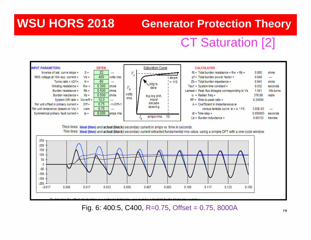
CT Saturation [5]
Fig. 6: 400:5, C400, R=0.75, Offset = 0.75, 8000A
CT Saturation [2]
Generator Protection
79
Generator ProtectionGenerator ProtectionGenerator ProtectionWSU HORS 2018 Generator Protection Theory
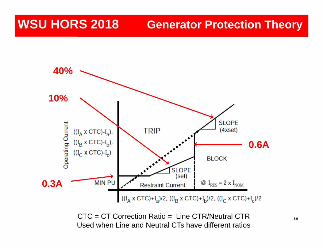
0.3A
10%
40%
0.6A
CTC = CT Correction Ratio = Line CTR/Neutral CTRUsed when Line and Neutral CTs have different ratios
Generator Protection
80
Generator ProtectionGenerator ProtectionGenerator ProtectionWSU HORS 2018 Generator Protection Theory

46: Negative Sequence Current
Generator Protection
Typically caused by open circuits in system
-Downed conductors-Stuck poles switches and breakers
Unbalanced phase currents create negative sequence current in generator stator and induces a double frequency current in the rotor
Induced current (120 Hz) into rotor causes surface heating of the rotor
81
Generator ProtectionGenerator ProtectionGenerator ProtectionWSU HORS 2018 Generator Protection Theory

Currents Flow in the Rotor Surface
Rotor End Winding Construction
Generator Protection
82
Generator ProtectionGenerator ProtectionGenerator ProtectionWSU HORS 2018 Generator Protection Theory
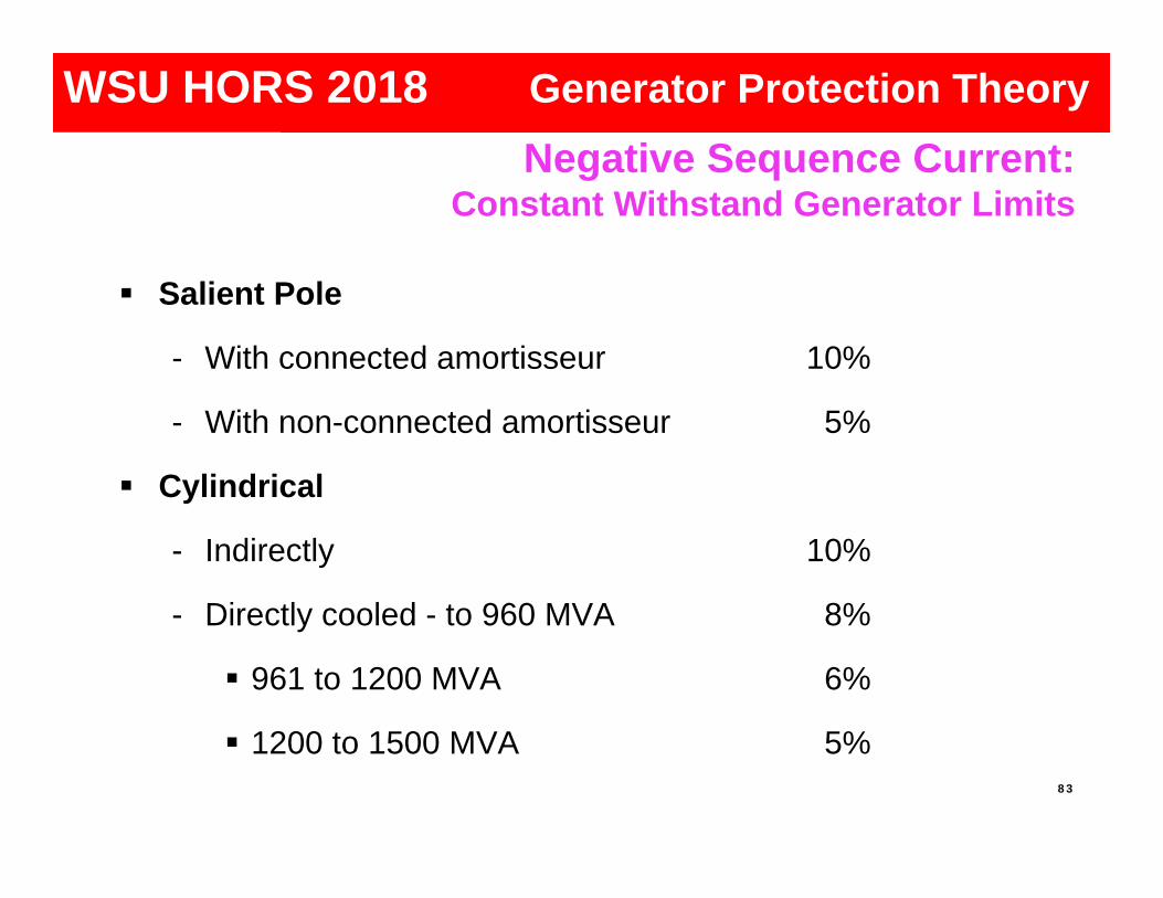
Salient Pole
- With connected amortisseur 10%
- With non-connected amortisseur 5%
Cylindrical
- Indirectly 10%
- Directly cooled - to 960 MVA 8%
961 to 1200 MVA 6%
1200 to 1500 MVA 5%
Negative Sequence Current: Constant Withstand Generator Limits
Generator Protection
83
Generator ProtectionGenerator ProtectionGenerator ProtectionWSU HORS 2018 Generator Protection Theory

Nameplate
- Negative Sequence Current (I2) Constant Withstand Rating
- “K” Factor
Negative Sequence Current: Constant Withstand Generator Limits
Generator Protection
84
Generator ProtectionGenerator ProtectionGenerator ProtectionWSU HORS 2018 Generator Protection Theory

GeneratorRatings
TypicalK Values
Salient Pole Generators40
CylindricalGenerators30
Generator Protection
85
Generator ProtectionGenerator ProtectionGenerator ProtectionWSU HORS 2018 Generator Protection Theory

Sensitivity restricted and cannot detect I2 levels less than 60% of generator rating
Fault backup provided
Generally insensitive to load unbalances or open conductors
46: Negative SequenceElectromechanical Relays
Generator Protection
86
Generator ProtectionGenerator ProtectionGenerator ProtectionWSU HORS 2018 Generator Protection Theory

Protects generator down to its continuous negative sequence current (I2) rating vs. electromechanical relays that don’t detect levels less than 60%
Fault backup provided
Can detect load unbalances
Can detect open conductor conditions
46: Negative Sequence Digital Relay
Generator Protection
87
Generator ProtectionGenerator ProtectionGenerator ProtectionWSU HORS 2018 Generator Protection Theory

Measured High Volts/Hertz ratio Normal = 120V/60Hz = 1pu Voltage up, and/or frequency low, make event
Issues Overfluxing of metal causes localized heating Heat destroys insulation Affects generators and transformers
Overexcitation (24)
Generator Protection
88
Generator ProtectionGenerator ProtectionGenerator ProtectionWSU HORS 2018 Generator Protection Theory

Causes of V/HZ Problems Generator voltage regulator problems
• Operating error during off-line manual regulator operation
• Control failure
• VT fuse loss in voltage regulator (AVR) sensing voltage
System problems
• Unit load rejection: full load, partial rejection• Power system islanding during major disturbances• Ferranti effect• Reactor out• Capacitors in• Runaway LTCs
Overexcitation (24)
Generator Protection
89
Generator ProtectionGenerator ProtectionGenerator ProtectionWSU HORS 2018 Generator Protection Theory

Modern Protection
Definite time elements• Curve modify• Alarm
Inverse curves• Select curve type for best coordination to
manufacturers recommendations• Employ settable reset timer
• Provides “thermal memory” for repeat events
Overexcitation (24)
Generator Protection
90
Generator ProtectionGenerator ProtectionGenerator ProtectionWSU HORS 2018 Generator Protection Theory

Example plot using definite time and inverse curve
Generator Protection
Overexcitation (24)
91
Generator ProtectionGenerator ProtectionGenerator ProtectionWSU HORS 2018 Generator Protection Theory

Modern Protection V/Hz measurement operational range: 2-80 Hz
- Necessary to avoid damage to steam turbine generators during rotor pre-warming at startup
- Necessary to avoid damage to converter-start gas turbine generators at startup
- In both instances, the generator frequency during startup and shut down can be as low as 2 Hz
NOTE: An Overvoltage (59) function, designed to work properly up to 120 Hz, is important for Hydro Generators where the generators can experience high speed (high frequency) during full load rejection. Since the V/Hz during this condition is low, the 24 function will not operate, and the 59 function will provide proper protectionfrom overvoltage.
Overexcitation (24)
Generator Protection
92
Generator ProtectionGenerator ProtectionGenerator ProtectionWSU HORS 2018 Generator Protection Theory

Generator Protection
Generator effects Synchronous generator becomes induction Slip induced eddy currents heat rotor
surface High reactive current drawn by generator
overloads stator
Power system effects Loss of reactive support Creates a reactive drain Can trigger system/area voltage collapse
40: Loss of Field
Can adversely effect the generator and the system!!
93
Generator ProtectionGenerator ProtectionGenerator ProtectionWSU HORS 2018 Generator Protection Theory

WATT
VAROUT
VARIN
Normal
Lossof
Field
TYPICAL GENERATOR CAPABILITY CURVE
Generator capability curve viewed on the P-Q plane.This info must be converted to the R-X plane.
Generator Protection
94
Generator ProtectionGenerator ProtectionGenerator ProtectionWSU HORS 2018 Generator Protection Theory

Increased Power Out
Increased Power Out
P-Q Plane
R-X Plane
TYPICAL GENERATOR CAPABILITY CURVEExcitation Limiters and Steady State Stability
Generator Protection
TRANSFORMATION FROM MW-MVAR TO R-X PLOT
95
Generator ProtectionGenerator ProtectionGenerator ProtectionWSU HORS 2018 Generator Protection Theory

Generator Capability Curve Limiting factors are rotor
and stator thermal limits
Underexcited limiting factoris stator end iron heat
Excitation control setting control is coordinated with steady-state stability limit (SSSL)
Minimum excitation limiter (MEL) prevents exciter from reducing the field below SSSL
Reactive Power Into System
Reactive Power Into Generator
Rotor Winding Limited
MEL
Stator End Iron Limited
SSSL
Stator Winding Limited
+ MWReal Power Into System0
+MVAR
Overexcited
Underexcited
–MVAR G
MVAR
MWSystem
MVARG
MWSystem
Generator Protection
96
Generator ProtectionGenerator ProtectionGenerator ProtectionWSU HORS 2018 Generator Protection Theory

Two Zone Offset Mho Impedance w/Directional UnitGE Westinghouse
CEH KLF
Loss of FieldGE and Westinghouse Methods
Generator Protection
97
Diameter = 1.0 puOffset =
Diameter = Xd
–R
–X
+X
+R
dX2
Machine Capability
MELSSSL
dX2
Generator ProtectionGenerator ProtectionGenerator ProtectionWSU HORS 2018 Generator Protection Theory

Loss of FieldTwo Zone Offset Mho
Generator Protection
98
dX2
Generator ProtectionGenerator ProtectionGenerator ProtectionWSU HORS 2018 Generator Protection Theory

Loss of FieldImpedance w/Direction Unit
Generator Protection
99
dX2
Generator ProtectionGenerator ProtectionGenerator ProtectionWSU HORS 2018 Generator Protection Theory

Generator Protection
Loss of Field Event
Generator ProtectionGenerator ProtectionWSU HORS 2018 Generator Protection Theory

Generator Protection
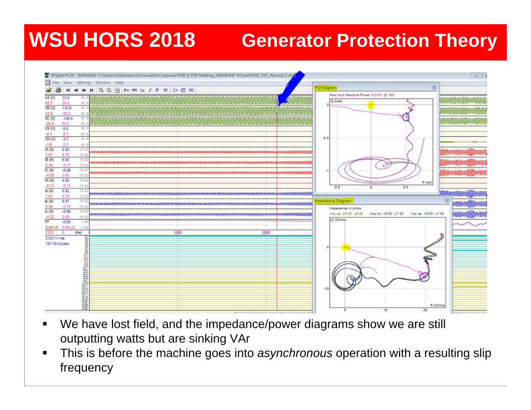
Blue arrow shows where we are in the record On R-X and P-Q diagrams, yellow square on axis shows where “0, 0” is. On R-X and P-Q diagrams, blue circles show where the R-X and P-Q
characteristics are respectively We have normal power output; lots of watts and a little VAr. All is good.
Generator ProtectionGenerator ProtectionWSU HORS 2018 Generator Protection Theory
Generator Protection
We have lost field, and the impedance/power diagrams show we are still outputting watts but are sinking VAr
This is before the machine goes into asynchronous operation with a resulting slip frequency
Generator ProtectionGenerator ProtectionWSU HORS 2018 Generator Protection Theory

Generator Protection
We have lost field, and the impedance/power plan plots show we are still outputting watts but are sinking lots of VAr
This is JUST before the machine goes into asynchronous operation with a slip
Generator ProtectionGenerator ProtectionWSU HORS 2018 Generator Protection Theory

Generator Protection
We have lost field, and the impedance/power plan plots show we are NOT putting out ANY watts and sucking a lot of VAr. The machine is slipping a pole.
At the instant shown, all the current into the machine is reactive (VAr sink).
Generator ProtectionGenerator ProtectionWSU HORS 2018 Generator Protection Theory

Generator Protection
The machine is slipping a pole. We are into the first slip cycle.
Generator ProtectionGenerator ProtectionWSU HORS 2018 Generator Protection Theory

Generator Protection
The machine is slipping a pole. We are into the first slip cycle.
Generator ProtectionGenerator ProtectionWSU HORS 2018 Generator Protection Theory

Phase distance backup protection may be prone to tripping on stable swings and load encroachment- Employ three zones
Z1 can be set to reach 80% of impedance of GSU for 87G back-up.
Z2 can be set to reach 120% of GSU for station bus backup, or to overreach remote bus for system fault back up protection. Load encroachment blinder provides security against high loads with long reach settings.
Z3 may be used in conjunction with Z2 to form out-of-step blocking logic for security on power swings or to overreach remote bus for system fault back up protection. Load encroachment blinder provides security against high loads with long reach settings.
- Use minimum current supervision provides security against loss of potential (machine off line)
Phase Distance (21)
Generator Protection
107
Generator ProtectionGenerator ProtectionGenerator ProtectionWSU HORS 2018 Generator Protection Theory

+X
‐X
+R‐R
L
T
Z1
Z2
Z3
LoadBlinder
or
FaultImpendance
Z1, Z2 and Z3 used to tripZ1 set to 80% of GSU, Z2 set to 120% of GSUZ3 set to overreach remote bus
(for Z1, Z2, Z3)21: Distance ElementWith Load Encroachment Blinder fro Z1, Z2, Z3
Stable Power Swing and Load Encroachment Blinding
Generator Protection
108
Generator ProtectionGenerator ProtectionGenerator ProtectionWSU HORS 2018 Generator Protection Theory

Power Swing orLoad Encroachment
Generator Protection
21: Distance ElementWith:• Power Swing
Blocking• Load
Encroachment Blocking for Z1 and Z2
109
Generator ProtectionGenerator ProtectionGenerator ProtectionWSU HORS 2018 Generator Protection Theory

Types of Instability• Steady State: Steady Voltage and Impedance (Load Flow)• Transient: Fault, where voltage and impedance change rapidly• Dynamic: Oscillations from AVR damping (usually low f)
Occurs with unbalance of load and generation• Short circuits that are severe and close• Loss of lines leaving power plant (raises impedance of loadflow path)• Large losses or gains of load after system break up
Generator accelerates or decelerates, changing the voltage angle between itself and the system
• Designed to cover the situation where electrical center of power system disturbance passes through the GSU or the generator itself
• More common with modern EHV systems where system impedance has decreased compared to generator and GSU impedance
Generator Out-of-Step Protection (78)
Generator Protection
110
Generator ProtectionGenerator ProtectionGenerator ProtectionWSU HORS 2018 Generator Protection Theory

• When a generator goes out-of-step (synchronism) with the power system, high levels of transient shaft torque are developed.
• If the pole slip frequency approaches natural shaft resonant frequency, torque produced can break the shaft
• High stator core end iron flux can overheat and short the generator stator core
• GSU subjected to high transient currents and mechanical stresses
Generator Out-of-Step Protection (78)
Generator Protection
111
Generator ProtectionGenerator ProtectionGenerator ProtectionWSU HORS 2018 Generator Protection Theory

Stability g s
e g s
E EP sin
X g s
max
E EP
X
g gE
s sE
For maximum power transfer:• Voltage of GEN and SYSTEM should be nominal – Faults lower voltage• Impedance of lines should be low – lines out raise impedance
Es - System VoltageEg - Generator Voltages - System Voltage Phase Angleg - Generator Voltage Phase AnglePe - Electrical Power
Generator Protection
112
Generator ProtectionGenerator ProtectionGenerator ProtectionWSU HORS 2018 Generator Protection Theory
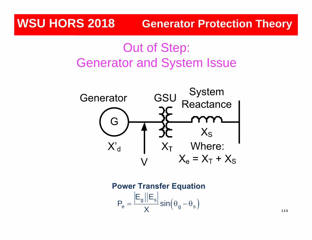
Out of Step:Generator and System Issue
Generator Protection
113 g s
e g s
E EP sin
X
Generator ProtectionGenerator ProtectionGenerator ProtectionWSU HORS 2018 Generator Protection Theory

Graphical Method: 78
X d
Gen
GSU
System
X
R
Mho Element
M
BA
P
Blinder Elements
B ElementPickup
A ElementPickup
XT
XS
2X D + XT + XS
Swing Locus
Generator ProtectionGenerator Protection
One pair of blinders (vertical lines)
Supervisory offset mho
Blinders limit reach to swings near the generator
Generator ProtectionGenerator ProtectionWSU HORS 2018 Generator Protection Theory

Graphical Method: 78
X d
Gen
GSU
System
X
R
Mho Element
BA
Blinder Elements
B ElementPickup
A ElementPickup
XT
XS
2X D + XT + XS
Unstable Swing
Stable Swing
Generator ProtectionGenerator ProtectionGenerator ProtectionGenerator ProtectionWSU HORS 2018 Generator Protection Theory

Generator Protection
Out-of-Step (Loss of Synchronism) Event
Generator ProtectionGenerator ProtectionGenerator ProtectionWSU HORS 2018 Generator Protection Theory

Off-Nominal Frequency Impacts Underfrequency may occur from system overloading
Loss of generation Loss of tie lines importing power
Underfrequency is an issue for the generator Ventilation is decreased Flux density (V/Hz) increases
Underfrequency limit is typically dictated by the generator and turbine Generator: V/Hz and loading Turbine: Vibration Issues
Overfrequency may occur from load rejection Overfrequency is typically not an issue with the generator
Ventilation is improved Flux density (V/Hz) decreases
Overfrequency limit is typically dictated by the turbine (vibration)
81-U
81-O
117
Generator ProtectionGenerator ProtectionGenerator ProtectionGenerator ProtectionWSU HORS 2018 Generator Protection Theory

System Frequency Overview
For overfrequency events, the generator prime mover power is reduced to bring generation equal to load
For underfrequency events, load shedding is implemented to bring load equal to generation It is imperative that underfrequency tripping for a generator be coordinated
with system underfrequency load shedding118
Generator Protection
Freq
uenc
y (H
z)
Generator ProtectionGenerator ProtectionGenerator ProtectionWSU HORS 2018 Generator Protection Theory

81 – Four Step Frequency
- Any step may be applied over- or underfrequency- High accuracy – 1/100th Hz (0.01 Hz)- Coordination with System Load Shedding
81A – Underfrequency Accumulator
- Time Accumulation in Six Underfrequency Bands- Limits Total Damage over Life of Machine
Typically used to Alarm
81R – Rate of Change of Frequency
- Allows tripping on rapid frequency swing
Abnormal Operating Conditions
Generator Protection
119
Generator ProtectionGenerator ProtectionGenerator ProtectionWSU HORS 2018 Generator Protection Theory

Freq
uenc
y (H
z)
60
59
58
57
0.001 0.01 0.10 1.0 10.0 100.0Time (Minutes)
Continuous
Restricted
Prohibited
Typical, from C37.106
Steam Turbine Underfrequency Operating Limitations
Generator Protection
120
Generator ProtectionGenerator ProtectionGenerator ProtectionWSU HORS 2018 Generator Protection Theory

Turbine Over/Underfrequency
Typical, from C37.106
Prohibited OperationRestricted Time
Operating Frequency Limits
Continuous Operation
Restricted Time Operating Frequency Limits
Prohibited Operation
62
61
60
59
58
57
56
0.0010.005
0.010.05
0.100.50
1.05.0
10.050.0
100.0Time (Minutes)
Freq
uenc
y (H
z)
121
Generator ProtectionGenerator ProtectionGenerator ProtectionGenerator ProtectionWSU HORS 2018 Generator Protection Theory

Turbine blades are designed and tuned to operate at rated frequencies
Operating at frequencies different than rated can result in blade resonance and fatigue damage
In 60 Hz machines, the typical operating frequency range: 18 to 25 inch blades = 58.5 to 61.5 Hz 25 to 44 inch blades = 59.5 and 60.5 Hz
Accumulated operation, for the life of the machine, not more than: 10 minutes for frequencies between 56 and 58.5 Hz 60 minutes for frequencies between 58.5 and 59.5 Hz
81A – Underfrequency Accumulator
Generator ProtectionGenerator ProtectionGenerator ProtectionGenerator ProtectionWSU HORS 2018 Generator Protection Theory

Causes of Inadvertent Energizing
Operating errors
Breaker head flashovers
Control circuit malfunctions
Combination of above
Generator Protection
123
Generator ProtectionGenerator ProtectionGenerator ProtectionWSU HORS 2018 Generator Protection Theory

Inadvertent Energizing:Protection Response
Typically, normal generator relaying is not adequate to detect inadvertent energizing• Too slow or not sensitive enough
• Distance• Negative sequence• Reverse power• Some types are complicated and may have
reliability issues• Ex., Distance relays in switchyard disabled for testing
and inadvertent energizing event takes place
Generator Protection
124
Generator ProtectionGenerator ProtectionGenerator ProtectionWSU HORS 2018 Generator Protection Theory

Inadvertent Energizing When inadvertently energized from 3-phase source, the machine acts
like an induction motor Rotor heats rapidly (very high I2 in the rotor)
Current drawn Strong system: 3-4x rated Weak system: 1-2x rated From Auxiliary System: 0.1-0.2x rated
When inadvertently energized from 1-phase source (pole flashover), the machine does not accelerate No rotating flux is developed Rotor heats rapidly (very high I2 in the rotor)
Protection system must be able to detect and clear both 3-phase and 1-phase inadvertent energizing events
Generator Protection
125
Generator ProtectionGenerator ProtectionGenerator ProtectionWSU HORS 2018 Generator Protection Theory

Inadvertent Energizing OscillographGenerator Protection
Inadvertent Energizing
126
Generator ProtectionGenerator ProtectionGenerator ProtectionWSU HORS 2018 Generator Protection Theory

Inadvertent Energizing Scheme
Undervoltage (27) supervises low-set, instant overcurrent (50) –recommended 27 setting is 50% or lower of normal voltage
Pickup timer ensures generator is dead for fixed time to ride through three-phase system faults
Dropout timer ensures that overcurrent elementgets a chance to trip just after synchronizing
Generator Protection
127
Generator ProtectionGenerator ProtectionGenerator ProtectionWSU HORS 2018 Generator Protection Theory

Fault Occurs
Fault ClearedProtective
Relay Time Breaker InterruptTime
Margin Time
Backup BreakerInterrupt Time
BFTrip
Command
Time
62 -1 BF Timer Time
BFI
Generator Protection
Breaker Failure Timeline
Generator ProtectionGenerator ProtectionGenerator ProtectionWSU HORS 2018 Generator Protection Theory

Breaker Pole Flashover & Stuck Pole
Generator Protection
129
Generator ProtectionGenerator ProtectionGenerator ProtectionWSU HORS 2018 Generator Protection Theory

50BF
AND
OR
AND
ProtectiveElements
50N
52/a
52/b
T0
TDOE
1= Flashover detected
1= Protection BFIBreaker Failure
BreakerFailure
Trip
Pole Flashover
OR
Breaker is closed by current detection or position
130
Generator Protection
Generator Breaker Failure and Pole Flashover Scheme:Simplified Conceptual View
Generator ProtectionGenerator ProtectionGenerator ProtectionWSU HORS 2018 Generator Protection Theory

Anti-Motoring: 32 Used to protect generator from motoring during loss of prime
mover power Motoring:
Wastes power from the system May cause heating in steam turbines as ventilation is greatly reduced Steam and dewatered hydro can motor with very little power; <=1%
rated CGT and Recip typically use 10-25% of rated power to motor
Generators are often taken off the system by backing off the power until importing slightly so not to trip with power export and go into overspeed (turbine issue) This is known as sequential tripping
Two 32 elements may be applied: Sequential trip (self reset, no lockout) Abnormal trip (lockout) Need great sensitivity, down to .002pu Usually applied as 32R, may be applied as 32F-U
131
Generator ProtectionGenerator ProtectionGenerator ProtectionGenerator ProtectionWSU HORS 2018 Generator Protection Theory

Generator Tripping and Shutdown
• Generators may be shutdown for unplanned and planned reasons• Shutdowns may be whole or partial• Shutdowns may lock out (86- LOR) or be
self resetting (94)
• Unplanned• Faults• Abnormal operating conditions
• Scheduled• Planned shutdown
132
Generator ProtectionGenerator ProtectionGenerator ProtectionGenerator ProtectionWSU HORS 2018 Generator Protection Theory

Generator Tripping
G
G
F
T
T = Turbine Trip
F = Field Trip
G = Generator Breaker Trip
133
Generator ProtectionGenerator ProtectionGenerator ProtectionGenerator ProtectionWSU HORS 2018 Generator Protection Theory

Tripping Philosophy & Sequential Tripping
– Unit separation• Used when machine is to be isolated from
system, but machine is left operating so it can be synced back to the system after separating event is cleared (system issue)
• Only generator breaker(s) are tripped
G
G
F
T
134
Generator ProtectionGenerator ProtectionGenerator ProtectionGenerator ProtectionWSU HORS 2018 Generator Protection Theory
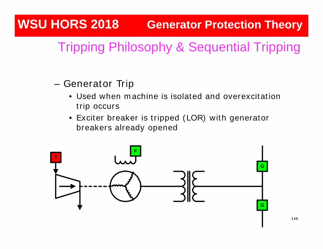
– Generator Trip• Used when machine is isolated and overexcitation
trip occurs• Exciter breaker is tripped (LOR) with generator
breakers already opened
G
G
F
T
Tripping Philosophy & Sequential Tripping
135
Generator ProtectionGenerator ProtectionGenerator ProtectionGenerator ProtectionWSU HORS 2018 Generator Protection Theory

– Simultaneous Trip (Complete Shutdown)• Used when internal (in-zone) protection asserts• Generator and exciter breakers are tripped (LOR)• Prime mover shutdown initiated (LOR)• Auxiliary transfer (if used) is initiated
G
G
F
T
Tripping Philosophy & Sequential Tripping
136
Generator ProtectionGenerator ProtectionGenerator ProtectionGenerator ProtectionWSU HORS 2018 Generator Protection Theory

– Sequential Trip• Used for taking machine off-line (unfaulted)
– Generator and exciter breakers are tripped (94)– Prime mover shutdown initiated (94)– Auxiliary transfer (if used) is initiated
G
G
F
T
Tripping Philosophy & Sequential Tripping
137
Generator ProtectionGenerator ProtectionGenerator ProtectionGenerator ProtectionWSU HORS 2018 Generator Protection Theory

Generator Protection
Sequential Tripping
Generator ProtectionGenerator ProtectionGenerator ProtectionWSU HORS 2018 Generator Protection Theory

Sequential Tripping
• Back down turbine and excitation– Backing down excitation to allows easier
better measurement of power
• Initiate Sequential Trip– Use 32 element that trips G, F and T, but
does not do this through a LOR– When a small amount of reverse power is
detected, trip G, F and T
Tripping Philosophy & Sequential Tripping
139
Generator ProtectionGenerator ProtectionGenerator ProtectionGenerator ProtectionWSU HORS 2018 Generator Protection Theory
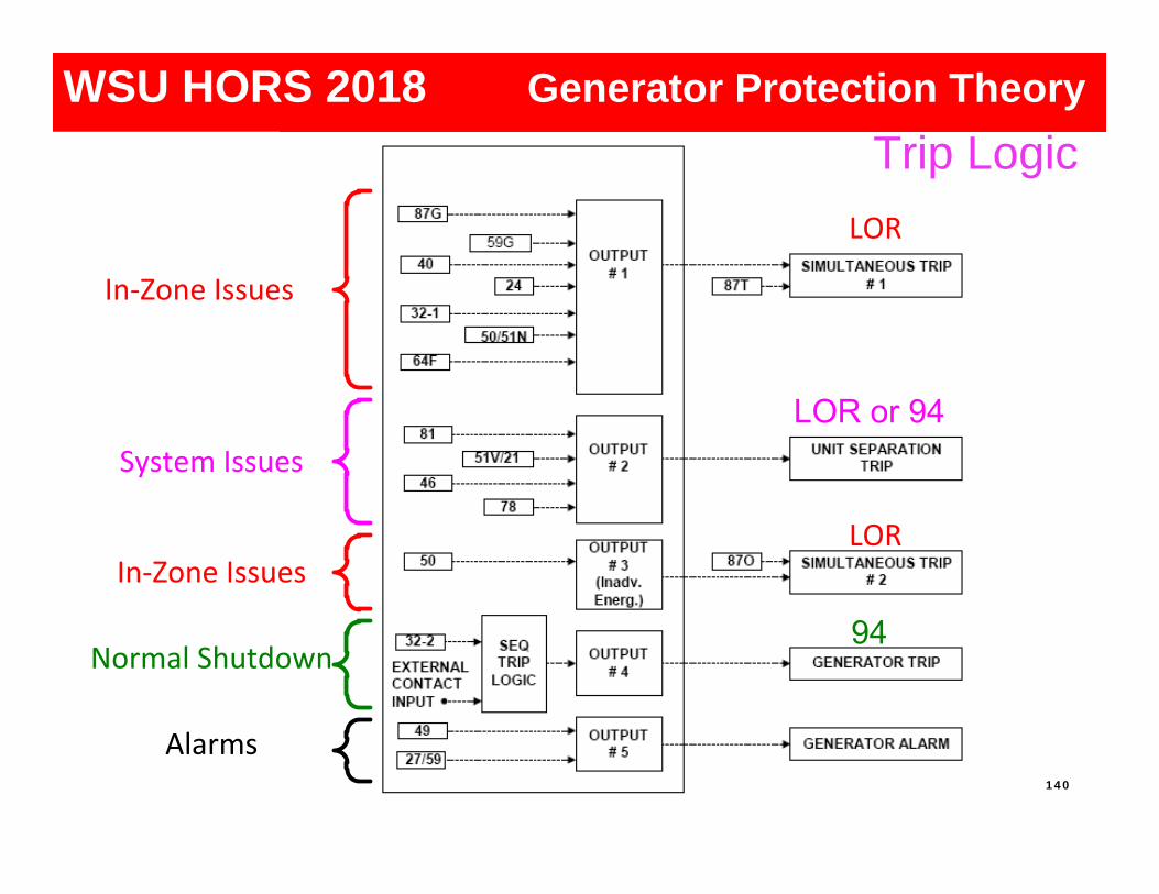
In-Zone Issues
System Issues
In-Zone Issues
Normal Shutdown
Alarms
LOR
LOR
Trip Logic
140
Generator ProtectionGenerator ProtectionGenerator ProtectionGenerator ProtectionWSU HORS 2018 Generator Protection Theory

Typical Protection Functions for a Large or Important Generator
141
Generator ProtectionGenerator ProtectionGenerator ProtectionGenerator ProtectionWSU HORS 2018 Generator Protection Theory

Mitigating Reliability Concerns
Integrating many protection functions into one package raises reliability concerns
Address these concerns by…
1. Providing two MGPRs, each with a portion or all of the protection functions (redundancy for some or all)
2. Providing backup for critical components, particularly the power supply
3. Using MGPR self-checking ability
142
Generator ProtectionGenerator ProtectionGenerator ProtectionGenerator ProtectionWSU HORS 2018 Generator Protection Theory

Aug 2003, NE Blackout: Generator Trips
531 Generators at 261 Power Plants tripped!!!
IEEE PSRC Survey Conducted in early ’90s, exposed
many areas of protection lacking Reluctance to upgrade:
• Lack of expertise• To recognize problems• To engineer the work• The thought that “Generators don’t
fault” • Operating procedures can prevent
protection issues
143
Generator ProtectionGenerator ProtectionGenerator ProtectionGenerator ProtectionWSU HORS 2018 Generator Protection Theory

Why Upgrade? Existing generator and transformer protection may:
Require frequent and expensive maintenance Cause coordination issues with plant control (excitation, turbine
control) Trip on through-faults (external faults), stable power swings, load
encroachment and energizing Not follow NERC PRC Standards (PRC = protection and control) Exhibit insensitivity to certain abnormal operating conditions and
fault types Not be self-diagnostic Lack comprehensive monitoring and communications capabilities
Not provide valuable event information that can lead to rapid restoration
Part of NERC Report comments on the August 03 Blackout Not be in compliance with latest ANSI/IEEE Standards!
Asset Reliability, Insurance, Liability Issues C37-102: Guide for the Protection of Synchronous Generators 144
Generator ProtectionGenerator ProtectionGenerator ProtectionGenerator ProtectionWSU HORS 2018 Generator Protection Theory

Improved sensitivity• Loss of Field• 100% stator ground fault• Reverse power• Negative sequence• Overexcitation
Improved Security• Directionally supervised ground differential
protection• Distance Element Enhancements
• Load encroachment blinding• Power swing blocking (for stable swings)
Protection Upgrade Opportunities
145
Generator ProtectionGenerator ProtectionGenerator ProtectionGenerator ProtectionWSU HORS 2018 Generator Protection Theory

Protection Upgrade Opportunities
New protections• Inadvertent energizing• VT fuse loss (integrated)
Special applications • Generator breaker failure
• Pole flashover (prior to syncing)
146
Generator ProtectionGenerator ProtectionGenerator ProtectionGenerator ProtectionWSU HORS 2018 Generator Protection Theory

Determine if relay and circuit breaker operated properly- Identify relay, control or breaker problem - Generators do experience faults / abnormal conditions
In the machine or the system?
Speed generator’s return to service- Identify type of testing needed- Provide data to generator manufacturer
Gives plant engineer data to force unit off-line for inspection
Uncovers unexpected problems- Synchronizing, shutdown
Oscillography
Generator Protection
147
Generator ProtectionGenerator ProtectionGenerator ProtectionWSU HORS 2018 Generator Protection Theory

Ph-Gnd Fault
Ph-Ph Fault3-Ph Fault
Example of Ph-Gnd fault evolving into 3-Ph FaultGen feeding fault into low side of GSU, no low side breaker
Insulation breakdown due to high voltage21P backup element tripped
Voltage collapse on Ph-Ph Fault
Long Records Let You See the Issue
Generator Protection
148
Generator ProtectionGenerator ProtectionGenerator ProtectionWSU HORS 2018 Generator Protection Theory

Generators require special protection for faultsand abnormal operations
These protections are for in-zone and out-of zoneevents
Modern element design matter for security anddependability
Complexity can be made simple with the correctuser tools
SummaryGenerator Protection
149
Generator ProtectionGenerator ProtectionGenerator ProtectionWSU HORS 2018 Generator Protection Theory

References1. IEEE Guide for Generator Ground Protection, ANSI/IEEE C37.101-2006.2. IEEE Guide for AC Generator Protection, ANSI/IEEE C37.102-2006.3. IEEE Tutorial on the Protection of Synchronous Generators, Second Edition,
2010; Special Publication of the IEEE Power System Relaying Committee.4. IEEE Recommended Practice for Grounding of Industrial and Commercial
Power Systems, IEEE Std. 142-1991.5. Protection Considerations for Combustion Gas Turbine Static Starting; Working
Group J-2 of the Rotating Machinery Subcommittee, Power System RelayCommittee.
6. Protective Relaying for Power Generation Systems; Donald Reimert, CRC Press2006; ISBN#0-8247-0700-1.
7. Practical Improvement to Stator Ground Fault Protection Using NegativeSequence Current; Russell Patterson, Ahmed Eltom; IEEE Transactions Paperpresented at the Power and Energy Society General Meeting (PES), 2013 IEEE.
8. Behavior Analysis of the Stator Ground Fault (64G) Protection Scheme; RamónSandoval, Fernando Morales, Eduardo Reyes, Sergio Meléndez and Jorge Félix,presented to the Rotating Machinery Subcommittee of the IEEE Power SystemRelaying Committee, January 2013.
9. Advanced Generator Ground Fault Protections; Wayne Hartmann, presented atthe Western Protective Relay Conference, October 2015.
Generator ProtectionGenerator ProtectionGenerator ProtectionGenerator ProtectionWSU HORS 2018 Generator Protection Theory