Generator Amg 1120mm10dse
347
User’s Manual Serial no. ABB ref. Project: ABB Synchronous Machine AMG 1120MM10DSE 4577169 3020HE401 July 2004 Grupo Punta Cana
-
Upload
miguel-angel-carpio -
Category
Documents
-
view
772 -
download
36
Transcript of Generator Amg 1120mm10dse

User’s Manual
Serial no.ABB ref.Project:
ABB
Synchronous MachineAMG 1120MM10DSE
45771693020HE401
July 2004 Grupo Punta Cana

Serial no.
AB
B ref.
Project:
Serial no.
AB
B ref.
Project:
Serial no.
AB
B ref.
Project:
Serial no.
AB
B ref.
Project:
Synchronous Machine
AM
G 1120M
M10D
SE 45771693020H
E401
Grupo P
unta Cana
Synchronous Machine
AM
G 1120M
M10D
SE 45771693020H
E401
Grupo P
unta Cana
Synchronous Machine
AM
G 1120M
M10D
SE 45771693020H
E401
Grupo P
unta Cana
Synchronous Machine
AM
G 1120M
M10D
SE 45771693020H
E401
Grupo P
unta Cana

User’s Manual
Serial no.ABB ref.Project:
ABB
Synchronous MachineAMG 1120MM10DSE
45771693020HE401
July 2004 Grupo Punta Cana
Contents
Introduction .............................1
Certificates ..............................2
Technical Specification ...........3
Mechanical Drawings ..............4
Electrical Drawings..................5
Manual ....................................6
Accessory Information.............7
Test Reports............................8
Check Lists..............................9
Additional Information ...........10

User’s Manual
Serial no.ABB ref.Project:
ABB
Synchronous MachineAMG 1120MM10DSE
45771693020HE401
July 2004 Grupo Punta Cana
1.Introduction

Synchronous Machine AMG 1120MM10DSESection 1 - Introduction
1
Introduction
1. General informationThis is the User’s Manual for the AMG 1120MM10DSE Synchronous Machine manufactured for project Grupo Punta Cana and forms the main documentation for this machine.
The purpose of this manual is to provide information for all aspects of installation, operation and maintenance of the machinery and shows how to disassemble/assemble major components, if required.
Actions shown in this manual are only to be performed by trained personnel authorized by the user.
2. Site conditionsThe machinery is to be used on a site with conditions according to Technical Specifications and Conditions laid down by ABB Oy in their contract with the user, and nowhere else.
3. Important NoteThe information in this document is subject to change without notice and should not be construed as a commitment by ABB Oy. ABB Oy assumes no responsibility for any errors that may appear in this document.
In no event shall ABB Oy be liable for direct, indirect, special, incidental or consequential damages of any nature or kind arising from the use of this document, nor shall ABB Oy be liable for incidental or consequential damages arising from use of any software or hardware described in this document.
This document and parts thereof must not be reproduced or copied without the express written permission of ABB Oy, and the contents thereof must not be imparted to a third party nor be used for any unauthorized purpose.
4. General SafetyCarrying out certain operations, maintenance procedures and some handling procedures can be dangerous or harmful if the correct safety precautions are not observed.
While it is important that these recommended safety procedures are observed, care near machinery is always necessary: no list can be exhaustive, always be on your guard!
It is important that personnel are aware of the hazards that exist within their working environment. Not only should they be able to identify these hazards, but they should be able to deal quickly and efficiently with the situation by carrying out recognized safety procedures. They should also be able to recognize warning signs (decals) and visual or audio signals.
The following recommendations are for general guidance:
a. Always wear correctly fitted protective clothing, headwear and footwear. Loose or baggy clothing can be lethal when working on or near rotating machinery. Clothing should be laundered regularly. Clothing which becomes impregnated with oil or other substances can constitute a health hazard due to prolonged contact with the skin, even through underclothing.

Synchronous Machine AMG 1120MM10DSESection 1 - Introduction
2
b. As far as is practicable, work on or close to machinery only when they are stopped. If this is not possible, keep tools, test equipment and all parts of your body well away from the moving parts of the machinery.
c. Parts of the synchronous machine and its auxiliary equipment can reach high temperatures. Protective clothing, particularly gloves must be worn at all times.
d. Many liquids used in machinery are harmful if swallowed or splashed into the eyes. In the event of accidentally swallowing a potentially dangerous fluid, do NOT encourage vomiting and OBTAIN MEDICAL ASSISTANCE IMMEDIATELY. Wear protective goggles when handling liquids which are harmful to the eyes. If any liquid is splashed into the eyes, wash out immediately and OBTAIN MEDICAL ASSISTANCE IMMEDIATELY.
Safety is dependent on the awareness, concern and prudence of all those who operate and service machines. The machinery may cause severe injury if incorrectly used. Personnel must be aware of the potential hazards that exist when operating or maintaining synchronous machines.
Before attempting to set up, operate or adjust synchronous machines, operators and maintenance people must be technically qualified and must have received the appropriate training.
Personnel must be familiar with the recommended procedures detailed in the Installation, Operation and Maintenance chapters of the Section 6, Manual.
4.1 Symbols and decalsPersonnel must be familiar with all the warning symbols and decals fitted to the machinery. Failure to recognize a warning and read the associated safety instructions may result in injury or death.
4.2 Electrical hazard The synchronous machine and auxiliary equipment must be disconnected from the electrical power supply during installation, maintenance or setting-up. All high-voltage parts must also be earthed.
4.3 Moving partsCovers must only be removed by qualified personnel when instructed as part of an installation, maintenance or setting-up procedure. They must be re-fitted as soon as possible. Keep hands and loose clothing clear of all moving parts.
4.4 High temperaturesParts of the machinery and its auxiliary equipment will reach high temperatures. Avoid contact with them. Always wear protective gloves when working in the vicinity.
4.5 Electro-Static Devices (ESD)Precautions must be taken to prevent damage to the electronic control devices of the synchronous machine. Ensure that the operating environment is protected against ESD. Do not touch electronic circuits while unpacking.

Synchronous Machine AMG 1120MM10DSESection 1 - Introduction
3
4.6 Magnetic fieldsThere is a magnetic field presence in the immediate area surrounding rotating machinery. Ensure that devices that can be influenced or wiped (e.g. magnetic disks, credit cards, watches etc.) by the effects of electro-magnetism are removed from the area.
4.7 NoiseMachine rooms can be extremely noisy and damaging to the ears. Ear protection should always be worn where practicable.
5. Safety Instructions (High-voltage AC Machines)
5.1 GeneralHigh-voltage machines rated at more than 1 kV have dangerous live and rotating parts and may have hot surfaces. All operations serving transport, connection, putting into service and maintenance shall be carried out by responsible skilled persons (in conformity with prEN 50 110-1 / DIN/VDE 0105 / IEC 364). Improper handling may cause serious personal injury and damage to property.
5.2 Intended useThese high-voltage machines are intended for industrial installations. They comply with the harmonized standards of the series EN 60034 / DIN VDE 0530. Their use in hazardous areas is prohibited unless they are expressly designed for such use (follow supplementary instructions).
On no account, use degrees of protection ≤ IP 23 outdoors. Air-cooled models are designed for ambient temperatures of -20°C up to 50°C and altitudes of ≤ 1000 m above sea level. Ambient temperature for air-/water-cooled models should be not less than +5°C (for sleeve-bearing machines, see manufacturer's documentation). By all means, take note of deviating information on rating plate. Field conditions must conform to all rating plate particulars.
High-voltage machines are components for installation in machinery within the meaning of the Machinery Safety Directive (MSD) 89/392/EEC. Putting into service is prohibited until conformity of the end product with this directive has been established (follow particular local safety and installation rules as e.g. EN 60204).
5.3 Transport, storageImmediately report damage established after delivery to transport company. If appropriate, prevent commissioning of the synchronous machine. Lifting points are dimensioned for the weight of the high-voltage machine, do not apply additional loads. If necessary, use suitable, adequately dimensioned means of transport (e.g. rope guides). Remove shipping brace (e.g. Roller or sleeve bearing locks, vibration dampers) before commissioning. Reuse the brace for further transports.
When storing high-voltage machines, make sure of dry, dust-free and low-vibration (Vrms ≤ 0.2 mm/s) location (danger of bearing damage at rest). Measure insulation resistance before commissioning. Always use space heaters in order to prevent humidity and condensation inside of the machine. Follow manufacturer's recommendations.

Synchronous Machine AMG 1120MM10DSESection 1 - Introduction
4
5.4 Installation Make sure of even support, solid foot or flange mounting and exact alignment in case of direct coupling. Avoid resonances with rotational frequency and double mains frequency as a result of assembly. Turn rotor, listen for abnormal slip noises.
Check direction of rotation in uncoupled state.
Mount or remove couplings or other drive elements only with appropriate means and cover them with touch guard. Avoid excessive radial and axial bearing loads (see manufacturer's documentation). The balance of the machine is done with half key as standard. The coupling must also be balanced accordingly.
In case of protruding, visible part of key, establish mechanical balance.
Make necessary ventilating pipe connections. Models with shaft ends pointing upward are to be provided with cover by customer. The ventilation must not be obstructed and the exhaust air, also of neighbouring sets, should not be taken in directly.
5.5 Electrical connectionAll operations must be carried out only by skilled persons on the high-voltage machine at rest. Before starting work, the following five safety rules must be strictly applied:
– De-energize!
– Provide safeguard against reclosing!
– Verify safe isolation from supply!
– Connect to earth and short!
– Cover or provide barriers against neighbouring live parts!
De-energize auxiliary circuits (e.g. anti-condensation heating).
Exceeding the limit values of zone A in EN 60034-1 / DIN VDE 0530-1 - voltage ± 5%, frequency ± 2%, form and symmetry - leads to higher temperature rise. Note rating plate particulars and connection diagram in terminal box.
The connection must be made thus, that permanently safe electrical continuity is maintained. Use appropriate cable terminations. Establish and maintain safe equipotential bonding.
The clearances between uninsulated, live parts and between such parts and earth must be according to IEC standard.
No presence of foreign objects, dirt or moisture is allowed in the terminal box. Close unused cable entrance holes and the box itself in a dust- and watertight manner. For trial run without output elements, lock fitting key. For high-voltage machines with accessories, check satisfactory functioning of these accessories before commissioning.
The proper installation (e.g segregation of signal and power lines, screened cables etc.) lies within the installer's responsibility.

Synchronous Machine AMG 1120MM10DSESection 1 - Introduction
5
5.6 OperationAcceptable vibration values have to be determined according to application and corresponding ISO standard. In case of deviations from normal operation - e.g elevated temperature, noises, vibrations - disconnect the synchronous machine, if in doubt. Establish cause and consult the manufacturer, if necessary.
Do not defeat protective devices, not even in trial run. In case of heavy dirt deposits, clean cooling system at regular intervals.
From time to time, open closed condensation drain holes, if any.
Regrease antifriction bearing with relubricating device while high-voltage machine is running. Follow instructions on lubricating plate.
In case of sleeve-bearing machines, observe the time limit for oil change.
Refer to manufacturer's documentation for noise level and information about the use of appropriate noise-reducing measures.
5.7 Maintenance and servicingAlways follow manufacturer's instructions in Section 6, Manual.
6. Disposal and recycling instructionsABB Oy is committed to its environmental policy. We strive continuously to make our products environmentally more sound by applying results obtained in recyclability and life cycle analyses. Products, manufacturing process as well as logistics have been designed taking into account the environmental aspects. Our environmental management system, certified to ISO 14001, is the tool for carrying out our environmental policy.
These instructions are trendsetting and it is on the customer’s responsibility to ensure that local the legislation is followed.
The material content (average percentage of the mass) which have been used in the manufacturing the electrical machine is the following:
Fabricated steel frame synchronous machines (AMG and AMZ)
Steel 81 %
Copper 13 %
Cast iron 2 %
Insulation materials 3 %
Other 1 %

Synchronous Machine AMG 1120MM10DSESection 1 - Introduction
6
6.1 Recycling of material required for transportAfter receiving the machine into the site, the package and the transportation locking have to be removed.
– The transportation locking is made of steel and can be recycled.
– The package is made of wood and can be burned.
– The sea trial package to some countries like Australia have special requirements, and is made of impregnated wood that must be recycled according to local instructions.
– The plastic material around the machine can be recycled.
– The rust protection material covering the machined surfaces can be removed with petrolbased solvent detergents and the cleaning rags are hazardous waste which have to be handled according to the local instructions.
6.2 Recycling of the complete machine
6.2.1 Dismantling of the machineBecause of the weight of the components, the person who does the dismantling has to have adequate skills to handle heavy components to prevent dangerous situations.
6.2.2 Frame, bearing housing, covers and fanThese parts are made of structural steel, which can be recycled according to local instructions. All the auxiliary equipment, cabling as well as bearings have to be removed before melting the material.
6.2.3 Components with electrical insulationThe stator and the rotor are the main components, which include electrical insulation materials. There are, however, auxiliary components which are constructed of similar materials and which are hence dealt with in the same manner. This includes various insulators used in the terminal box, excitation machine, voltage and current transformers, power cables, instrumentation wires, surge arrestors and capacitors. Some of these components are used only in synchronous machines and some are used only in very limited number of machines.
All these components are in an inert stage once the manufacturing of the machine has been completed. Some components, in particular the stator and the rotor, contain a considerable amount of copper which can be separated in a proper heat treatment process where the organic binder materials of the electrical insulation are gasified. To ensure a proper burning of the fumes the oven shall include a suitable after burning unit. The following conditions are recommended for the heat treatment and for the after burning to minimize the emissions from the process:
1) Heat treatment
Temperature: 380…420° C (716…788 F)
Duration: After receiving 90 % of the target temperature the object shall stay a minimum of five hours at this temperature
2) After burning of the binder fumes
Temperature: 850…920° C (1562…1688 F)

Synchronous Machine AMG 1120MM10DSESection 1 - Introduction
7
Flow rate: The binder fumes shall stay a minimum of three seconds in the burning chamber
NOTE: The emission consists mainly of O2-, CO-, CO2-, NOx-, CxHy-gases and microscopic particles. It is on the user’s responsibility to ensure that the process complies with the local legislation.
NOTE: The heat treatment process and the maintenance of the heat treatment equipment require special care in order to avoid any risk for fire hazards or explosions. Due to various installations used for the purpose it is not possible for ABB Oy to give detailed instructions of the heat treatment process or the maintenance of the heat treatment equipment and these aspects must be taken care by the customer
6.2.4 Hazardous wasteThe oil from the lubrication system is a hazardous waste and has to be handled according to local instructions
6.2.5 Landfill wasteAll insulation material can be handled as a land fill waste.

User’s Manual
Serial no.ABB ref.Project:
ABB
Synchronous MachineAMG 1120MM10DSE
45771693020HE401
July 2004 Grupo Punta Cana
2.Certificates

User’s Manual
Serial no.ABB ref.Project:
ABB
Synchronous MachineAMG 1120MM10DSE
45771693020HE401
July 2004 Grupo Punta Cana
ContentsCertificates

Synchronous Machine AMG 1120MM10DSESection 2 - Certificates
Declaration of Incorporation
Article 4(2) of Directive 89/392/EEC, as amended
The manufacturer ABB OYP.O. Box 186FIN-00381 HelsinkiFinland
hereby declares that the product described below
Synchronous Machine AMG 1120MM10DSE
may not be put into service before the machinery into which it will be incorporated is declared to comply with the provisions of Directive 89/392/EEC, as amended, and with the regulations transposing it into national law.
Helsinki, 2 July 2004 ABB Oy
Electrical Machines
User’s Manual
Serial no.ABB ref.Project:
ABB
Synchronous MachineAMG 1120MM10DSE
45771693020HE401
July 2004 Grupo Punta Cana
3.TechnicalSpecification
User’s Manual
Serial no.ABB ref.Project:
ABB
Synchronous MachineAMG 1120MM10DSE
45771693020HE401
July 2004 Grupo Punta Cana
ContentsTechnical Specification
Technical Specification .....................................1

We reserve all rights in this document and in the information contained therein. Reproduction, use or disclosure to third parties without express authority is strictly forbidden. © ABB
Prep. Helena Krivetz/PTD 17.3.2004 TECHNICAL SPECIFICATION No. of sh.
Appr. PTD Project 6 Resp. dept. PTD Document number Lang. Rev. ind. Sheet
ABB Oy / Machines en A 1 TEMPLATE: TECHNICALSPECIFICATION.DOT; FILENAME: 3020HE_401_A_TECHSPEC; PRINTDATE: 2.7.2004 14:50; SAVEDATE: 17.3.2004 15:59
TECHNICAL SPECIFICATION Project name: Grupo Punta Cana Our reference number: 3020HE401 Customer’s reference number: P/04007-Grupo Punta Cana Customer: WÄRTSILÄ FINLAND OY Final customer: Application: Diesel/Gas engine Type designation: AMG 1120MM10 DSE
NOTES
CONTENTS
SECTION:
1 PERFORMANCE DATA ( Calculated values) 2
2 CONFIGURATION AND SCOPE OF SUPPLY 4
3 ACCESSORIES 6

Document number Lang. Rev. ind. Sheet
ABB Oy / Machines en A 2 TEMPLATE: TECHNICALSPECIFICATION.DOT; FILENAME: 3020HE_401_A_TECHSPEC; PRINTDATE: 2.7.2004 14:50; SAVEDATE: 17.3.2004 15:59
1 PERFORMANCE DATA ( Calculated values) TYPE
Type designation: AMG 1120MM10 DSE RATINGS
Output: 8713 kVA Direction of rotation Duty: S1 (Facing drive end): CCW Voltage: 12470 V Stored energy constant Current: 403 A (Rotative energy divided Power factor: 0,80 by rated effect): 0,78 s Frequency: 60 Hz Weight: 26500 kg Speed: 720 rpm Inertia: 2400 kgm^2 Overspeed: 864 rpm Protection by enclosure: IP23 Cooling method: IC0A1 Mounting arrangement: IM1101 STANDARDS
Applicable standard: IEC Marine classification: None Hazardous area classification: None Temperature rise stator / rotor: F/F Insulation class: F ENVIRONMENTAL CONDITIONS
Ambient temperature: 50 °C Altitude: 1000 masl Coolant temperature: °C Location: ASSUMED DATA
Driving equipment: Wärtsilä 16V32 Appr. mec. power: 7165 kW EFFICIENCY in %
load: 110 % 100 % 75 % 50 % 25 % Efficiency @ power factor 0,80 97,30 97,31 97,19 96,63 94,44 Efficiency @ power factor 1,00 98,09 98,08 97,94 97,46 95,66 REACTANCES IN %
XD (U): 165,2 XD’ (S): 29,2 XQ’’ (S): 17,3 X0 (U): 10,9 XQ (U): 84,1 XD’’ (S): 17,2 X2 (S): 17,3 XP (S): 24,1 X1 (U): 14,7 (S) = Saturated value, (U) = Unsaturated value TIME CONSTANTS (SEC.) AT 75 °C
TD0’: 5,819 TD’: 1,131 TQ0’’: 0,1059 TA: 0,103 TD0’’: 0,02679 TD’’: 0,01605 TQ’’: 0,0239

Document number Lang. Rev. ind. Sheet
ABB Oy / Machines en A 3 TEMPLATE: TECHNICALSPECIFICATION.DOT; FILENAME: 3020HE_401_A_TECHSPEC; PRINTDATE: 2.7.2004 14:50; SAVEDATE: 17.3.2004 15:59
RESISTANCES AT 20 °C
Stator winding: 0,0716 Ω Field winding: 0,8242 Ω Excitation winding: 5,9 Ω SHORT CIRCUIT
Short circuit ratio: 0,74 Sustained short circuit current: 1,9 p.u. (rated excitation) > 2.5 p.u. (voltage regulator) Sudden short circuit current: 2350 A (symmetric RMS) 5950 A (peak value) VOLTAGE VARIATION
Maximum allowed amount of starting load:
Maximum voltage drop Power factor Load 15 % 0.1 4400 kVA 15 % 0.4 4700 kVA 15 % 0.8 6500 kVA 20 % 0.1 6100 kVA 20 % 0.4 6500 kVA
Voltage drop at sudden increase of rated load: 19 % Voltage rise at sudden drop of rated load: 25 % REACTIVE LOADING
Steady state reactive loading at rated excitation: 7150 kVAR Steady state reactive loading at zero excitation: 4050 kVAR TORQUE
Rated load torque (Calculated of rated output in kVA): 115600 Nm
The peak values of sudden short circuit air gap torques: 2-phase short circuit: 710 % 3-phase short circuit: 520 % TERMINAL CONNECTIONS
Direction of main connection: Right down Direction of zero connection: Left down EXCITATION
Exciter field No load: 3,7 A 27,7 V Rated load: 8,4 A 63,4 V

Document number Lang. Rev. ind. Sheet
ABB Oy / Machines en A 4 TEMPLATE: TECHNICALSPECIFICATION.DOT; FILENAME: 3020HE_401_A_TECHSPEC; PRINTDATE: 2.7.2004 14:50; SAVEDATE: 17.3.2004 15:59
2 CONFIGURATION AND SCOPE OF SUPPLY GENERAL
The generator is designed to operate together with a diesel engine. CONSTRUCTION
The stator frame is a rigid welded steel structure construction. The stator core is built of thin electric sheet steel laminations which are insulated on both sides with heat-resistant inorganic resin. The radial cooling ducts in the stator core insure uniform and effective cooling of the stator.
The rotor consists of a shaft poles fixed on the shaft, exciter and a fan(s). The shaft is
machined of steel forging. The poles are manufactured of 2 mm sheet steel and bolted from the top to the shaft. The pole laminations are pressed together with steel bars which are welded to the end plates. The exciter rotor and the fan are shrink fitted onto the shaft and secured with a key.
All windings are completely vacuum pressure impregnated with high quality epoxy resin. The
windings are provided with very strong bracing which withstands all expected mechanical and electrical shocks and vibrations as well as chemicals. For more information ask for brochure "MICADUR-Compact Industry Insulation System".
The stator frame, core support and endshields are made of fabricated steel and welded
together. The stator frame is closed with steel panels that guide the ventilation air and provide the degree of protection required. The flange mounted bearings are bolted to the endshields.
According to IM1101 the machine has 2 bearings. The feet are raised. The shaft end is
cylindrical. FOUNDATION
The machine can be mounted using shimming, machined blocks, chock fast or on grouted sole plates or bed plate. Before using other mountings, contact us.
COOLING
The machine has a shaft mounted fan inside. The surrounding air is used for cooling. The cooling air is drawn in through air filters (self charging electrostatic panels) and blown out to the surrounding environment.
CONTROL SYSTEMS
A three phase transformer supplies the excitation power to the field winding of the shaft driven three phase exciter under the control of the digital automatic voltage regulator (AVR) type ABB UNITROL 1000. A three phase voltage feedback is supplied by the voltage transformer. A current feedback is provided by the current transformer. The transformers are installed in the generator. In addition to voltage control mode UNITROL 1000 AVR can be used in P.F., Var or field current control modes. Operational limits, like over and under excitation, machine voltage and Volts/Hz are implemented in the AVR. Static reactive power compensation in parallel operation and several other software functions are also included. The AVR-plate is supplied as

Document number Lang. Rev. ind. Sheet
ABB Oy / Machines en A 5 TEMPLATE: TECHNICALSPECIFICATION.DOT; FILENAME: 3020HE_401_A_TECHSPEC; PRINTDATE: 2.7.2004 14:50; SAVEDATE: 17.3.2004 15:59
a loose item for installation in the control cubicle. Thanks to a permanent magnet pole in the exciter no external power source is required for initial excitation at start-up. The permanent magnet pole is already magnetised by the generator manufacturer. Should the re-magnetisation of the permanent magnet be necessary, rated values for re-magnetisation given on the main connection diagram of the generator are used. Thanks to Soft Start function it is possible to avoid over shooting at start-up. Excitation power at short circuit is supplied by the CTs through rectifier. At normal voltage the contactor is shorting the output of CTs (and preventing over excitation from these CTs). At a line short circuit AVR will notice the voltage drop and connect CTs to give full short circuit excitation. The CTs are rated for sustaining a short circuit current at least 250 % of rated current. The circuit breaker protects the field circuit and the AVR against thermal overload and short circuit. The over voltage relay will trip the circuit breaker in excess of pre-set limit of over voltage and thus interrupt the supply of the excitation power to the AVR. Auxiliary supply can be 9 to 250 Vac (3-phase), 50 to 250 Vac (1-phase) or 18 to 300 Vdc. UNITROL 1000 AVR can be operated using digital and analogue I/O signals, from local panel or with PCTools software. PCTools is a commissioning and maintenance tool running under Microsoft Windows. With PCTools the tuning of the AVR can be done easily, also by using preset parameter files. The operation of a synchronous machine can be monitored and controlled by an on-line power chart, four channel oscilloscope and by several measurements and status indications with trending and memory functions. Measured data and parameters can be saved to a file for future use and analysis.
TESTING
Testing is according to IEC and ABB internal requirements. The test may be observed by the customer without extra charges. The test procedures is described in the following PIF -files: PIF 3a-315, PIF 3a-316. These are available upon request. Other tests to be agreed separately.
Estimated vibration level is 2,3 mm/s SURFACE TREATMENT
Colour: RAL 5019 Grade: C1 - Default
The surface treatment of the machines is based on epoxy paint system, which includes solvent free topcoat. This paint system is suitable especially for urban and industrial atmospheres with moderate corrosive attack (ISO 12944-2, C2 and C3 without direct UV-radiation). Total film thickness is 180 um.
DOCUMENTATION
User's Manual in electronic format. Documentation language is English.

Document number Lang. Rev. ind. Sheet
ABB Oy / Machines en A 6 TEMPLATE: TECHNICALSPECIFICATION.DOT; FILENAME: 3020HE_401_A_TECHSPEC; PRINTDATE: 2.7.2004 14:50; SAVEDATE: 17.3.2004 15:59
3 ACCESSORIES No pc/pcs Item
1 Drive-end sleeve bearing Side flange mounted sleeve bearing for AMG/Z 1120 in land application. D-end.
Normal end float +/- 2.5 mm or +/- 1/8 inch Max. axial force 2 kN. Machine seal on machine side IP44. Floating labyrinth seal on outer side IP44.
1 Non-drive-end sleeve bearing Side flange mounted sleeve bearing
Insulation between bearing housing and shell
6 PT100 for stator winding - PYR PT100LG7/3 - 60042012
2 PT100 for sleeve bearings
2 Anticondensation heater - RER 1-800W/490V - 9871215 Voltage 380-480 V, power 2x500-800 W
1 Voltage transformer for exc.power & actual value measurement - KSG 3PU180/63/E - 70006553
12470/110/110 V, 60 Hz Secondary 1: 110 V 3200VA for excitation Secondary 2: 110 V 300VA for actual value measurement
1 Current transformer for actual value measurement - KSG 0500T2 - 9872228 500/1A, 5 VA, CL 0.5, 60 Hz
3 Current transformer for differential protection - ACI-17 - 9877349 500/5/5 A, 60 Hz
Core 1: 20VA, 5P10 Core 2: 20VA, 5P10
1 Coupling half, Mounting of machined coupling half The machined coupling half must be delivered latest 2 weeks before testing to our factory.
3 Current transformer for short circuit exc.power - KSG IFJ-3-500T3 - 9874480 500/7.0 A, CL 3/10P2.5, 60 Hz
1 Automatic Voltage Regulator with plate - Unitrol 1000
2 Multidiameter cable entry seals (Rox System) for main cables
3 Diode module - LNM 260A/2000V - MITTA ABB Stock code: 9877911

Synchronous Machine AMG 1120MM10DSESection 3 - Technical Specification
7
Protection for Synchronous Generators
Subject: standard generators
Applicable for voltage 1 - 15 kV and power 3 - 40 MVA
Recommended protectionFor generator itself
1. Thermal overload in stator winding; I >
2. Network short-circuit; I >>
3. Stator interwinding short-circuit; Differential protection relay
4. Stator earth-fault; Earth-fault relay
5. Overvoltage; Over voltage relay
6. Unbalance load or shorted turns in the same phase; I2 / In
7. Underexcitation and loss of synchronism; Under reactance relay
8. Undervoltage and intermittent loss of voltage; Under voltage relay
9. Temperature supervision of temperature detectors; Pt-100-monitoring
Additional protection Essential rather for prime mover than for generator
1. Frequency disturbance
2. Reverse power

Synchronous Machine AMG 1120MM10DSESection 3 - Technical Specification
8
Max. Allowed Unbalanced Load for Standard Generators
Subject: standard generators
I2 is a counter rotating component of stator current In
Max. continuous rate of I2 is 8%
0
100
200
300
400
500
0 10 20 30 40 50 60 70 80 90 100
sec

Synchronous Machine AMG 1120MM10DSESection 3 - Technical Specification
9
Underfrequency Withstanding Capability After Continuous Operation at Rated Output
Subject: standard generators
Frequency Load at rated voltage
% P.F.=0.8 P.F.=1.0 No load
P=Pn P=Pn P=0
100 cont. cont. cont.
96 cont. cont. cont.
95 30 min cont. cont.
92.5 2 min 30 min cont.
90 2 min cont.
87.5 30 min
85 2 min

Synchronous Machine AMG 1120MM10DSESection 3 - Technical Specification
10
Current Through Stator Core Lamination Versus Time
Subject: standard generators
A = NEGLIGIBLE ARC BURNING
B = SLIGHT BURNING
C = SEVERE DAMAGE
t/sec
I/A
0
10
20
30
40
50
60
70
0 1 2 3 4 5 6 7 8 9 10 11 12 13 14 15
C
B
A

Synchronous Machine AMG 1120MM10DSESection 3 - Technical Specification
11
Overcurrent Limit for Standard Generators
Subject: standard generators
150 % for 2 minutes
125 % for 15 minutes
110 % for 1 hour
In = Rated current
I = Max. allowed current at six-hour intervals
1
2
3
4
5
6
7
8
9
10
11
0 2 4 6 8 10 12 14 16 18 20
sec

Synchronous Machine AMG 1120MM10DSESection 3 - Technical Specification
12
Loadability of Standard Generators
Subject: standard generators
110 % for 1 hour
100 % continuously
Sn = Rated output
S = Output with rated p.F. at six-hour intervals
0 ,9
1
1 ,1
1 ,2
1 ,3
1 ,4
1 ,5
1 ,6
0 1 0 2 0 3 0 4 0 5 0 6 0
m in
User’s Manual
Serial no.ABB ref.Project:
ABB
Synchronous MachineAMG 1120MM10DSE
45771693020HE401
July 2004 Grupo Punta Cana
4.MechanicalDrawings

User’s Manual
Serial no.ABB ref.Project:
ABB
Synchronous MachineAMG 1120MM10DSE
45771693020HE401
July 2004 Grupo Punta Cana
ContentsMechanical Drawings
Main Dimensions ..................................5135523
Assembly Drawing ................................5122349
Rotor Drawing .......................................5135510
Transport and Hoist ................................530650
Removing of Transport Locking ............5122342
ET-dimension........................................5122341
Removing Rotor ....................................5122343
D-end Bearing.......................................9874569
N-end Bearing.......................................9872686


User’s Manual
Serial no.ABB ref.Project:
ABB
Synchronous MachineAMG 1120MM10DSE
45771693020HE401
July 2004 Grupo Punta Cana
5.ElectricalDrawings

User’s Manual
Serial no.ABB ref.Project:
ABB
Synchronous MachineAMG 1120MM10DSE
45771693020HE401
July 2004 Grupo Punta Cana
ContentsElectrical Drawings
Main Connection Diagram ....................5132715
Layout of Connection ............................5133125
Terminal Box for Accessories ...............5122340
Exciter Rotor with Diode Bridge ............5122347
Unitrol 1000 Wärtsilä..............3BHS116994 E01
Unitrol 1000 Circuit Diagram..3BHS116747 E20


UN
ITR
OL
44 e
+Vdig
18 L2M+Vref
U1L1
2
32I M
2 17S2S1 16
33
+AI 1
AI 1
34
-
UN
ETI
L13L3
45L2
76L3
8+
39
23
AO 1
37
20
-AI 2
19
+AI 3
-AI 3
36
Vref
35
+
AI 2 +
21
-Vref
22
38
-Vref
25
AGND
24
AO 2
40
DGND
Vdig
41
+
DIO 1
26
+Vdig
27
43
DI 6
DI 5
42
ESC
54
seria
l por
t
UAU
XPW
RU
12L3L1
(+)
9-10
11L2(-)
L2(-)
13L1(+
)14
15L3
46
30
DIO 3
DIO 2
2928
+Vdig
45
DI 7
DI 8
DIO 4
31DGND
47EI
A-48
5
5250+
5153
-+
55-
100
0
OK®

F
1
E
D
2 3 4
C
B
A
1 2 3 4
5 6 7 8
F
E
D
5 6 7
C
B
8
A
ZAB A2General tolerances
HZN 401 638; DIN 7168 T.1;linear and angular tolerances <<medium>> <<course>>
ISO 2768 DIN 7168 T.2:..Geometrical tolerances
therein. Reproduction, use or disclosure to third parties without
We reserve all rights in this document and in the information contained
express authority is strictly forbidden. ASEA BROWN BOVERI 1999
3BHS116747_E20
WÄRTSILÄ
UN1000 CIRCUIT DIAGRAM WÄRTSILÄ 11012512
%26.07.2002 Rietmann
26.07.2002 Ehlen
26.07.2002 Ehlen
ATPE
E 13291
X
3BHS116747_E20 office resp.:
checked:
dervd. from:
released:
replaces:
issued:
recei. office:
formatdoc.-type
sep. PL another no.
change
sep. PL same no.no sep. parts list
scale:
3BHE006720R0001
U generator I field U power U AUX I L2
1 2 3 7 8 9 10 11 12 13 14 15 16 17 18 19 20 21 22 23 24 25 26 27 28 29 30 31 32 33 34 35 36 37 38 39 40 41 42 43 44 45 46 47
+Vre
f
L1 L2 L3 + - L1(+) L3 L3L2(-) L1(+) L2(-) S1 S2 INC
DEC
-Vre
f
If/pv
f/syn
c
AGN
D
+Vdi
g
ON
/off
GC
B
+Vdi
g
GC
B/
Ik/
+ PF
- PF
+Vre
f
PFre
m
-Vre
f
stat
us
clos
e ct
r
boos
t ctr
DG
ND
+Vdi
g
SYN
C
PWG
+Vdi
g
PF/ VD
C
DG
ND
U-d
roop
U-d
roop
stat
us
activ
e
+ -
63 73 74
- +
OVERVOLTAGERELAY
1L1
2T1
3L2
4T2
5L3
6T3
+
A1
A2
K01
A1
K02
A2
6261
4
6
24
21
68 66
DecreaseONOFF
UNITROL 1000 WÄRTSILÄR
+ -
64 65 67 6970
14
11A1
A2
K03
IG
POWER SUPPLYUG IG
GENERATOR FIELD
V02
V01
F01
A01
PE
123
13
14
5
U03
76 77
SelectRemote
R03
4 5 6L3
U busbarL1 L2
10
2
9
1
11
3
12
4
13
A1 A2
14
ReferenceIncreaseReference
Ref. Input
-0,75...1...+0,75Range
75
2.5mm2
2.5mm2
2.5mm2
-X1
R04
78
1413
A2A1
72
U02
13 14
A1 A2
71
U01
PE
4mm2
ALL WIRES WITHOUT INDICATION: 1.0mm² black
yellow/green
13 14 13 14 13 14
A2 A2 A2
black
black
black
2.5mm2black
4mm2yellow/green
123
ECL-10
121110987654
F02
79 80
EXCITATIONON/OFF

User’s Manual
Serial no.ABB ref.Project:
ABB
Synchronous MachineAMG 1120MM10DSE
45771693020HE401
July 2004 Grupo Punta Cana
6.Manual

Synchronous Machine AMG 1120MM10DSESection 6 - Manual
i
Chapter 1 - Introduction1.1 General information............................................................................................... 11.2 Important note........................................................................................................ 11.3 Site conditions........................................................................................................ 1
Chapter 2 - Transport and Storage2.1 Transport and unpacking........................................................................................ 1
2.1.1 Protective measures prior to transport .................................................. 12.1.2 Lifting the machine package................................................................. 12.1.3 Check upon arrival................................................................................ 12.1.4 Unpacking............................................................................................. 12.1.5 Lifting of unpacked machine ................................................................ 2
2.2 Storage ................................................................................................................... 32.2.1 Short term storage (less than 2 months)................................................ 32.2.2 Long term storage (2-6 months) ........................................................... 32.2.3 Very long term storage (over 6 months) ............................................... 42.2.4 Storage and care after installation......................................................... 5
Chapter 3 - Installation and Alignment3.1 Preparations for installation ................................................................................... 1
3.1.1 General.................................................................................................. 13.1.2 Check of foundation.............................................................................. 2
3.2 Installation ............................................................................................................. 23.3 Rough levelling and alignment .............................................................................. 2
3.3.1 Rough levelling..................................................................................... 33.3.2 Rough axial alignment .......................................................................... 3
3.4 Alignment and air gap checking ............................................................................ 43.4.1 Air gap check ........................................................................................ 43.4.2 Alignment ............................................................................................. 53.4.3 Correction for thermal expansion ......................................................... 8
3.5 Final inspection and installation ............................................................................ 93.5.1 Covers and enclosures .......................................................................... 9
Chapter 4 - Mechanical and Electrical Connections4.1 Electrical connections ............................................................................................ 1
4.1.1 General information.............................................................................. 14.1.2 Connection of main power cables......................................................... 14.1.3 Earth connection ................................................................................... 24.1.4 Insulation distances of main power connections .................................. 24.1.5 Connection of auxiliaries and instruments............................................ 3
Chapter 5 - Commissioning5.1 General................................................................................................................... 15.2 Check of mechanical installation........................................................................... 15.3 Check of electrical installation .............................................................................. 1
Synchronous Machine AMG 1120MM10DSESection 6 - Manual
ii
5.4 Insulation resistance measurements....................................................................... 25.5 Starting................................................................................................................... 25.6 Checks during running of the machine .................................................................. 3
5.6.1 Normal vibration levels ........................................................................ 35.6.1.1 Measurement procedures and operational conditions .... 35.6.1.2 Evaluation of RIC engine generating sets...................... 4
5.6.2 Temperature levels ................................................................................ 55.7 Shut down .............................................................................................................. 6
Chapter 6 - Operation6.1 Start up procedure .................................................................................................. 1
6.1.1 Start interlocking................................................................................... 16.2 Continuous supervision.......................................................................................... 16.3 Shut down procedures............................................................................................ 1
Chapter 7 - Maintenance7.1 Preventive maintenance ......................................................................................... 17.2 Safety precautions.................................................................................................. 1
7.2.1 Particular safety instructions for winding maintenance........................ 17.3 Maintenance of general construction..................................................................... 2
7.3.1 The tightness of fastenings ................................................................... 27.3.2 Vibration and noise ............................................................................... 3
7.4 Maintenance of lubrication system and bearings................................................... 47.4.1 Lubrication............................................................................................ 4
7.4.1.1 Lubrication oil temperature............................................ 47.4.1.2 General characteristics of the listed oil qualities ........... 47.4.1.3 Condition of the lubricant .............................................. 47.4.1.4 Oil qualities .................................................................... 57.4.1.5 Oil change schedule for mineral oils.............................. 5
7.4.2 Sleeve bearings ..................................................................................... 57.4.2.1 Oil level.......................................................................... 67.4.2.2 Oil leakage ..................................................................... 67.4.2.3 Bearing temperature ....................................................... 6
7.4.3 Bearing insulation resistance check...................................................... 77.4.3.1 Procedure ....................................................................... 7
7.5 Maintenance of stator and rotor winding............................................................... 87.5.1 The timing of the maintenance ............................................................. 97.5.2 The correct operating temperature........................................................ 97.5.3 Insulation resistance test ....................................................................... 9
7.5.3.1 Conversion of measured insulation resistance values.... 97.5.3.2 General considerations ................................................. 107.5.3.3 Minimum values for insulation resistance ................... 117.5.3.4 Stator winding insulation resistance measurement ...... 127.5.3.5 Rotor field winding insulation resistance
measurement ................................................................ 13

Synchronous Machine AMG 1120MM10DSESection 6 - Manual
iii
7.5.4 The polarization index ........................................................................ 137.5.5 High voltage test ................................................................................. 14
7.5.5.1 High voltage test for stator winding............................. 147.5.6 Fault searching methods ..................................................................... 14
7.5.6.1 Voltage drop test (Rotor winding impedance test) ....... 147.5.7 Tan delta-measurements ..................................................................... 147.5.8 Visual winding inspection................................................................... 15
7.5.8.1 Corrective actions based upon the observations .......... 157.5.9 Cleaning the windings ........................................................................ 16
7.5.9.1 Cleaning methods......................................................... 167.5.9.2 Cleaning agents ............................................................ 17
7.5.10 Drying ................................................................................................. 197.5.11 Varnishing of the windings ................................................................. 197.5.12 Other maintenance operations ............................................................ 20
7.6 Maintenance related to electrical performance, excitation, control, and protection ...................................................................................................... 207.6.1 Exciter insulation resistance measurement ......................................... 207.6.2 Protection trips.................................................................................... 217.6.3 Automatic voltage regulator (AVR).................................................... 217.6.4 Pt-100 resistance temperature detectors ............................................. 21
7.6.4.1 Pt-100 temperature detector retrofitting....................... 227.6.5 Insulation resistance measurement for auxiliaries .............................. 247.6.6 Diode fault .......................................................................................... 24
7.7 Maintenance related to thermal performance and cooling system ...................... 257.7.1 Cooling System................................................................................... 25
7.7.1.1 Cleaning ....................................................................... 267.8 Maintenance program .......................................................................................... 26
7.8.1 Recommended maintenance program................................................. 297.8.1.1 General construction .................................................... 297.8.1.2 High voltage connection .............................................. 307.8.1.3 Stator and rotor............................................................. 307.8.1.4 Excitation system, control and protection.................... 317.8.1.5 Lubrication system and bearings.................................. 327.8.1.6 Cooling system............................................................. 32
7.9 Spare parts............................................................................................................ 327.9.1 General considerations........................................................................ 327.9.2 Wearing parts subjected to mechanical wear ...................................... 337.9.3 Other wearing parts............................................................................. 337.9.4 Selection of the most suitable spare part package .............................. 337.9.5 Typical recommended spare parts in different sets............................. 34
7.9.5.1 Safety package ............................................................. 347.9.5.2 Maintenance package ................................................... 34
7.9.6 Order information ............................................................................... 357.10 Troubleshooting ................................................................................................... 36
7.10.1 Mechanical performance..................................................................... 37

Synchronous Machine AMG 1120MM10DSESection 6 - Manual
iv
7.10.2 Lubrication system and bearings ........................................................ 387.10.2.1 Lubrication system and sleeve bearings....................... 38
7.10.3 Thermal performance.......................................................................... 397.10.3.1 Thermal performance, open air cooling system........... 39
7.10.4 Electrical performance........................................................................ 407.10.4.1 Electrical performance and excitation system
of generators................................................................. 41
Chapter 8 - Dismantling and Reassembly8.1 General................................................................................................................... 18.2 Preparation for dismantling ................................................................................... 18.3 Dismantling............................................................................................................ 18.4 Removing the rotor ................................................................................................ 28.5 Reassembly and Realignment................................................................................ 48.6 Stator Shift ............................................................................................................. 4
Chapter 9 - After Sales and Market Support

Synchronous Machine AMG 1120MM10DSESection 6 - Manual
Introduction - 1
Chapter 1 Introduction
1.1 General informationThe following chapters contain information on the transporting, installing, operating and maintaining of the AMG 1120MM10DSE synchronous machine manufactured for project Grupo Punta Cana.
The purpose of this manual is also to provide information for all aspects of removal and assembly of components.
Actions shown in this manual are only to be performed by trained personnel authorized by the user.
1.2 Important noteThe information in this document may sometimes be of a general nature and applicable to the various machines produced by ABB Oy.
Where a conflict exists between the contents herein and the actual machinery supplied, the user must either make an informed engineering judgement as to a course of action or, if any doubt exists, contact ABB Oy.
In no event shall ABB Oy be liable for direct, indirect, special, incidental or consequential damages of any nature or kind arising from the use of this document, nor shall ABB Oy be liable for incidental or consequential damages arising from use of any software or hardware described in this document.
The safety precautions shown in Section 1, Introduction must be observed at all times.
This document and parts thereof must not be reproduced or copied without the express written permission of ABB Oy, and the contents thereof must not be imparted to a third party nor be used for any unauthorized purpose.
1.3 Site conditionsThis machine is to be used on a site with environmental conditions according to the ABB Oy specifications (listed in Section 1, Introduction and Section 3, Technical Specification).
Please refer to the applicable certificate in Section 2, Certificates. Special conditions stipulated in the certificate must be strictly followed.

Synchronous Machine AMG 1120MM10DSESection 6 - Manual
Transport and Storage - 1
Chapter 2 Transport and Storage
2.1 Transport and unpacking
2.1.1 Protective measures prior to transport• All synchronous machines delivered as a unit are provided with an axial movement
locking device protecting the bearings against damages during the transport. Therefore it is important that the locking device is attached whenever the machine is transported.
• Machined metal surfaces, such as the shaft extension, are provided with an anti-corrosive coating before delivery.
• The bearings are flooded with oil during the tests prior to delivery. This gives sufficient protection against corrosion.
• During shipping the machine should be placed under deck.
2.1.2 Lifting the machine packageThe package has marks that have to be observed, i.e. showing where the lifting wires are to be applied.
Lifting must be performed with great care and using long enough slings. . For details, see the lifting drawing in Section 4, Mechanical Drawings.
NOTE: Do not attempt to lift the machine from the red attaching points!
NOTE: If the ambient temperature is below -20 ºC, the machine may not be lifted or operated without permission from the manufacturer.
2.1.3 Check upon arrivalThe machine and the package must be inspected immediately upon arrival. Any transport damage must be reported within less than one (1) week after arrival if transport insurance is to be claimed. It is therefore important that evidence of careless handling is checked and reported immediately to the transport company and the supplier.
A machine which is not to be installed immediately upon arrival must not be left without supervision or without protective precautions. For more details, see Chapter 2.2 Storage.
2.1.4 UnpackingPlace the synchronous machine so that it does not hinder the handling of any other goods and on a flat, vibration-free surface.
When the package has been removed, a check should be made to see that the synchronous machine is not damaged and that all accessories are included. Tick off the accessories on the packing list which is enclosed. If there is any damage, suspected damage, or if accessories are missing, please report this immediately to the supplier.

Synchronous Machine AMG 1120MM10DSESection 6 - Manual
Transport and Storage - 2
2.1.5 Lifting of unpacked machineLifting must be performed with great care and using slings long enough to assure the lifting angle requirements. If the requirements are not met, there is a risk of damage. See Figure 2-1 Lifting an unpacked machine. For more details, see the lifting drawing in Section 4, Mechanical Drawings.
NOTE: The machine must be lifted from its frame. Do not attempt to lift the machine from the top cover!
Figure 2-1 Lifting an unpacked machine
Figure 2-2 Lifting an unpacked machine

Synchronous Machine AMG 1120MM10DSESection 6 - Manual
Transport and Storage - 3
2.2 Storage
2.2.1 Short term storage (less than 2 months)• The machine should never under any circumstances, not even in transportation package, be
left outdoors as it is. If the ground is wet, the package needs to be placed on supports so that there is at least 100 mm between the wet level and package bottom. If the package needs to be stored outdoors, it has to be provided with a big enough cover that protects it completely from rain, but allows ventilation.
• The machine must be placed in a clean and dry place. The temperature, dew point, dust, shock and vibration should be controllable. The storage temperature should preferably range from 10ºC to 50ºC with a maximum air humidity of 75%. If air humidity is more than 75%, good internal ventilation must be arranged. Anticondensation heaters must be energised to keep the machine above the dew point of the ambient air to prevent condensation of moisture. When surrounding air temperature is higher than 50ºC ventilation is necessary to prevent overheating of the electrical equipment, especially when the anticondensation heaters are energised.
• The floor under the machine should be free from excessive vibrations. If the vibrations are suspected to be too large, precautions should be taken to isolate the machine by e.g. placing rubber blocks under the machine.
2.2.2 Long term storage (2-6 months)
In addition to the measures described in Chapter 2.2.1 Short term storage (less than 2 months) above, the following should be done
Storage indoors• If the machine is stored in its transportation package, make big enough holes on the sides
of the transportation package so that the D-end and N-end of the machine are accessible.
• Protect the shaft and the sealing points as well as all bearing parts against corrosion. Shaft and bearing seals should be treated with an anti-corrosive agent (e.g. LPS 3, Holt Lloyd, USA). The bearing should be filled with protective oil, e.g.
– Esso: Rust-Ban 623
– Gulf: Gulf No-Rust Engine Oil Grade 2
– Mobil: Mobilarma 524
– Shell: Shell Ensis Engine Oil 20
• If the protection made by the manufacturer has been removed, protect the unpainted surfaces such as shaft extensions, coupling halves and jacking screws with suitable anti corrosion agent.
• If the machine has been delivered in fully assembled condition, the rotor shall be turned approximately 10 revolutions once per every 2-3 months to maintain protective oil film on bearing surfaces. The self-lubricated bearings must be filled with oil, and flood lubricated bearings must be connected to the lubrication system. If this cannot be done, the bearing shells should be taken out, see chapter Storage outdoors .

Synchronous Machine AMG 1120MM10DSESection 6 - Manual
Transport and Storage - 4
Storage outdoorsFor outdoor storage in addition to the measures described in chapter Storage indoors , the following should be done.
• Make sure that the machine is completely covered with a big enough waterproof cover.
• Remove the side and end covers of the machine.
• Push strong cardboard pieces into the air gap between the main machine stator and rotor so that the rotor may be supported by the stator.
• Dismount the bearing instruments.
• Dismount the seals and the upper parts of the bearing housings.
• Remove the upper parts of the bearing shells and dismount the eventual oil rings.
• Lift the rotor up (approx. 0.5 mm) until the bearing shells do not carry the weight of the rotor.
• Turn the lower bearing shells 180º over the shaft and remove them.
• Lower the rotor so that it rests on the stator (cardboard pieces in between).
• Protect the bare shaft surfaces and shells with anti corrosive agent.
• Mount the bearing housings and seals (seals have to be loosened) and protect the seals with anti-corrosion agent.
• Store the bearing shells in a clean and dry place.
NOTE: Do not damage the seals or the bearings.
2.2.3 Very long term storage (over 6 months)• All the protected surfaces mentioned in the previous list in Chapter 2.2.1 Short term
storage (less than 2 months) and Chapter 2.2.2 Long term storage (2-6 months) should be cleaned and the anti-corrosive treatment should be renewed every 12 months. Otherwise the instructions for shorter storage periods should be followed.
Regular checkings during storage
Every month• Check that the anticondensation heaters are working.
• Check that the ventilation works.
Every 3 months• Check the insulation resistance, see Chapter 7.5.3 Insulation resistance test.
• Check that there is no corrosion on the surfaces. If corrosion is observed, remove the corrosion and protect the surfaces.
• Check that the anti-corrosion agents have not cracked.
Every 6 months• Dismount the bearing housing upper cover and check the shaft and the bearing housing
anti-corrosion protection.

Synchronous Machine AMG 1120MM10DSESection 6 - Manual
Transport and Storage - 5
2.2.4 Storage and care after installation• If the machine will not be in operation for a longer period of time after installation, the
same measures as above in Chapter 2.2.1 Short term storage (less than 2 months) should be applied. Remember to rotate the shaft 10 revolutions at least every 2-3 months. The self-lubricated bearings must be filled with oil.

Synchronous Machine AMG 1120MM10DSESection 6 - Manual
Installation and Alignment - 1
Chapter 3 Installation and Alignment
3.1 Preparations for installation
3.1.1 GeneralGood planning and preparation result in simple and correct installation and assure safe running conditions and maximum accessibility.
During installation, general as well as local work safety instructions must be followed.
Auxiliary tools for the installation should be made available on site if required:
• Suitable material for set-up and shimming as well as other auxiliary tools for installation are normally not included in ABB Oy delivery. Auxiliary tools for installation, like hydraulic jack and bracket plates with adjusting screws are to be supplied by the customer.
• Attachments for gauges, extension brackets and other alignment tools are to be made.
• Before the rotor is turned, oil must be poured into the bearings. A lever is needed for turning the rotor. While turning the rotor, oil must be continuously poured into the funnels at both ends of the machine, see Figure 3-1 Pouring oil into the bearings.
• For suitable oil qualities, see Chapter 7.4.1 Lubrication.
Figure 3-1. Pouring oil into the bearings.
NOTE: Anti-condensation heaters must be provided for keeping the machine interior dry when there is a risk of condensation. The machine must be protected against dust and rain.
The general tightening torques for screws are given in Chapter 7.3.1 The tightness of fastenings. These values are applicable if no specific tightening torques are given in this manual or in the

Synchronous Machine AMG 1120MM10DSESection 6 - Manual
Installation and Alignment - 2
mechanical and electric drawings, see Section 4, Mechanical Drawings and Section 5, Electrical Drawings.
3.1.2 Check of foundationThe structural design of the foundation is not included in the ABB Oy scope and the customer or a third party is therefore responsible for this.
The installation of the machine should be planned as early as possible.
Before lifting the synchronous machine onto the foundation a check should be made to ensure that the foundation fulfills the following requirements:
• Check that the position of the anchoring or fixing holes and the height of the foundation are in agreement with corresponding measurements on outline and foundation drawings in Section 4, Mechanical Drawings.
• The foundation must be flat. If any inclination has been agreed upon the permissible inclination must be stated on the installation drawing.
• The foundation must be carefully cleaned by sweeping or vacuum-cleaning for some days before the testing is performed.
• Use of non-shrinking concrete.
3.2 InstallationThe machine is normally transported and lifted as one ready assembled unit onto the foundation, see Section 4, Mechanical Drawings.
Main steps of the installation procedure are:
1. Mount the coupling halves, if applicable.
2. Mount the machine on the foundation.
3. Level and align the machine roughly in axial and horizontal directions.
4. Align and couple the rotor with driven equipment.
5. Fasten the machine initially to the foundation.
6. Check air gaps and adjust as necessary.
7. Re-check the alignment. Fine adjust if necessary.
8. Tighten and lock bolts and install dowel pins.
9. Install accessories.
More detailed instructions for installation are given in following chapters or in instructions supplied by driven/driving machine manufacturer.
3.3 Rough levelling and alignmentBefore alignment remove the transport locking device according to instructions in Transport Locking drawing in Section 4, Mechanical Drawings. The transport locking device is normally painted red.

Synchronous Machine AMG 1120MM10DSESection 6 - Manual
Installation and Alignment - 3
3.3.1 Rough levelling1. Center the rotor (axially) to the middle of the end float of the drive end bearing. Check also
that the distance ET is the same as the value stamped above the D-end bearing. See Figure 3-3 Typical marking of ET dimension and Section 4, Mechanical Drawings.
2. Remove the anti-corrosive coating from surfaces requiring uncoated metal surfaces during normal operation.
3. Check the coupling instructions and fit. Preheat the coupling hub as necessary and mount it on the machine shaft.
4. Lift the machine up and move it over the bed plate.
5. Align the machine visually and put pieces of sheet metal below the jacking screws to protect bed plate surface.
6. Turn the jacking screws until they carry the weight of machine.
Check that the machine is radially and axially leveled.
Place a spirit level on the horizontal surfaces of the frame and rotor shaft as shown in Figure 3-2 Placement of the spirit level and make adjustments by placing shims under the feet. The machine must be supported by all feet.
Figure 3-2. Placement of the spirit level
3.3.2 Rough axial alignmentCorrect axial position of the rotor is shown by the magnetic center indicator above the shaft. Position is correct when the tip of the indicator is in line with the machined groove on the shaft
The rotor is placed in the magnetic center position when the dimension ET is fulfilled. Read the correct distance in the inspection and test record in Section 8 under ET Dimension. The dimension has also been punched on the D-end of the machine, see Figure 3-3 Typical marking of ET dimension and Section 4, Mechanical Drawings for details.
If the rotor has axial float, check the mechanical center position of the rotor.

Synchronous Machine AMG 1120MM10DSESection 6 - Manual
Installation and Alignment - 4
The running center is not the same as magnetic center due to the fact that the machine has a radial fan for cooling and the fan has an axial component that will affect the rotor running position.
If there is no thrust bearing, the machine cannot withstand any axial force from the driven machine. The axial force must be carried by the driven machine. The coupling must be of limited axial float type.
If there is an axially locating bearing on the machine, make sure that continuous free axial movement is possible between the coupling halves (excluding rigid couplings) in order to permit thermal expansion of the machine shaft without damaging the bearings.
When the machine stands axially in its right position, leave all adjusting jacking screws only lightly tightened.
Figure 3-3. Typical marking of ET dimension
3.4 Alignment and air gap checking
3.4.1 Air gap checkCheck the air gap of the electrical machine between the stator and the rotor. Remove the side covers, or where applicable, the end covers of the machine frame. Push a wedge-shaped measuring strip in the air gap at the middle of one pole in four symmetrically chosen rotor positions. Turn the rotor correspondingly. Where applicable, there is a hole in the fan through which the measuring can be done. Make sure that the bearings are filled with oil before turning the rotor.
NOTE: Centering of the rotor, i.e. the air gap, is adequate when a single measured value does not deviate more than 10 percent from the mean value.
The air gap of the stator and the rotor of the electrical machine is adjusted by loosening the bolts retaining the end shield, removing the dowel pins, and moving the complete end shield by turning the two adjustment screws situated on each side of the end shield.
ET dimension

Synchronous Machine AMG 1120MM10DSESection 6 - Manual
Installation and Alignment - 5
After the air gap of the stator and the rotor of the electrical machine has been checked and adjusted, the air gap between the exciter stator and rotor, at the N-end of the machine, has to be checked in four symmetrically chosen positions. The exciter air gap is adjusted by moving the exciter stator.
Figure 3-4. Air gap between stator and rotor
After the adjustment of the air gap, all the fastening bolts are tightened, see Table 7-1 General tightening torques (combined stress 0.75 times yield stress). The air gap is then verified once more, where appropriate dowel pins are inserted.
3.4.2 Alignment
General
After the machine has been roughly positioned, as described in Chapter 3.3 Rough levelling and alignment, the final alignment can start.
This step must be performed with great caution. Failure to do so can result in serious vibrations and damage to both driving and driven machine.
The alignment is done in accordance with the recommendations given by the coupling manufacturer. Parallel, angular and axial alignment of the machine is required. Some standard publications give recommendations for coupling alignment, e.g. BS 3170:1972 "Flexible couplings for power transmission". In accordance with common practice, parallel and angular misalignment should not exceed 0.05-0.10 mm and axial misalignment should not exceed 0.10 mm, see Figure 3-5 Definition of misalignment. The corresponding run-out is 0.10-0.20 mm for parallel and angular misalignment, and 0.20 for axial misalignment.
Exciterair gap
Air gap

Synchronous Machine AMG 1120MM10DSESection 6 - Manual
Installation and Alignment - 6
Parallel misalignment ∆r
Angular misalignment ∆b
Axial misalignment ∆a
Figure 3-5. Definition of misalignment
The tolerances given by the coupling manufacturers must not be used in deciding how accurate the alignment should be, because these tolerances indicate what the coupling can accept. Excessive tolerances will give rise to vibrations, bearing damage etc. and therefore tolerances as narrow as recommended above should be aimed at.
Alignment
The alignment of the machine is performed according to these guidelines.
1. The machine should stand on its jacking screws.
2. Rotate the rotor and check the axial end float, see Chapter 3.3.2 Rough axial alignment.
Lubricate the bearings at regular intervals during the final alignment in accordance with Chapter 3.1 Preparations for installation.
3. Mount the alignment equipment. If gauges are used, it is practical to adjust the dial gauge in such way that approximately half of the scale is available in either direction. Check the rigidity of the gauge brackets in order to eliminate the possibility of sag, see Figure 3-6 Alignment check with gauges.

Synchronous Machine AMG 1120MM10DSESection 6 - Manual
Installation and Alignment - 7
Figure 3-6. Alignment check with gauges
4. Measure and note readings for parallel, angular and axial misalignment in four different positions: top, bottom right and left, i.e. every 90°, while both shafts are turned simultaneously. Readings are recorded in the Commissioning Report in Section 9.
5. Align the machine vertically by turning the jacking screws, the adjustment screws or by jacking with hydraulic jacks.To facilitate the alignment in the vertical plane, jacking screws are fitted to the feet of the horizontal machine. See Figure 3-7 Vertical positioning of machine foot.The alignment accuracy of the machine is sometimes affected by the thermal expansion of its frame. The maximum thermal expansion of the frame can be taken as 0.5 mm per meter, corresponding to a temperature rise of 50°C. In most operating conditions, the temperature rise of the frame remains at about 40°C with a corresponding thermal expansion of 0.4 mm per meter. See Chapter 3.4.3 Correction for thermal expansion.
Figure 3-7. Vertical positioning of machine foot
Angular alignmentRadial alignment
Machine foot
Jackingscrew
Fixingbolt
Shim
Foundation

Synchronous Machine AMG 1120MM10DSESection 6 - Manual
Installation and Alignment - 8
6. Measure the distance between the bottom of the machine feet and the bed plate and make corresponding solid blocks or wedges or reserve necessary amount of shims.
7. Fit the solid blocks or shims under the stator feet. Slacken the jacking screws and tighten the fixing bolts.
8. Check the alignment again.
9. Check the air gap of the machine and the exciter.
10. Draw up a record for future checks (Section 9, Check Lists).
11. Re-tighten nuts and lock the nuts by tack welds or hitting sufficiently hard with a center punch.
3.4.3 Correction for thermal expansionTemperatures have a considerable influence and should be considered during the alignment. The temperature of the machine is lower during installation than it will be during operating conditions. For this reason the shaft centre is going to lie higher during operating conditions.
Depending on the type of coupling, the distance between the machine and the driven equipment may have to be compensated because of thermal expansion.
The upward thermal expansion of the electrical machine can be approximated according to the following formula:
∆H = α × ∆T × H [mm]where α = 10 × 10-6 K-1
∆T = 40 KH = shaft height [mm]
Due to the thermal expansion of the electrical machine, the vertical movement of the shaft is of the magnitude of 0.1 mm for each 10oC difference in temperatures as illustrated in Figure 3-8 The correlation between thermal expansion and machine temperature.

Synchronous Machine AMG 1120MM10DSESection 6 - Manual
Installation and Alignment - 9
Figure 3-8. The correlation between thermal expansion and machine temperature
3.5 Final inspection and installation
3.5.1 Covers and enclosuresAfter the machine has been erected, aligned and its accessories are installed, check carefully that no tools or foreign objects have been left inside of the enclosure. Clean also any dust or debris.
When installing the covers, check that all sealing strips are intact before mounting them on.
Store alignment and assembly accessories together with the transport locking devices for future use.

Synchronous Machine AMG 1120MM10DSESection 6 - Manual
Mechanical and Electrical Connections - 1
Chapter 4 Mechanical and Electrical Connections
4.1 Electrical connections
4.1.1 General informationThe safety information in Section 1, Introduction Chapter 6 Safety Instructions (High-voltage AC Machines) must be observed at all times. Connection diagrams received with the machine have to be studied before starting the installation work, see Section 5, Electrical Drawings. It is important to verify that the supply voltage and the frequency are the same as the values indicated on the rating plate of the machine and in Section 3, Technical Specification.
The sizes of input cables have to be adequate for the maximum load current and in accordance with local standards. The cable terminations have to be of appropriate type and of correct size. The connection of all devices, such as temperature probes, has to be checked.
NOTE: Prior to installation work it is important to check that the incoming cables are separated from the supply network. The cables should be grounded.
4.1.2 Connection of main power cablesThe stator terminals are marked with letters U, V and W according to IEC 34-8 or T1, T2, and T3 according to NEMA. Stripping, splicing and insulating of the high-voltage cables must be performed in accordance with instructions by the cable manufacturer. The lugs should not be permanently tightened by busbars, but only attached (for checking of insulation resistance).
The cables must be supported so that no stress is applied to the busbars in the terminal box, see connection diagram in Section 5, Electrical Drawings.
When three-phase cables are used, the prescribed distance must be maintained between the leads at intersections. Bracing and spacers should be used if necessary.
Check the phase sequence, see Figure 4-1 Phase sequence (IEC) (CW = clockwise, CCW = counter clockwise) and Figure 4-2 Phase sequence (NEMA) (CW = clockwise, CCW = counter clockwise).
Figure 4-1 Phase sequence (IEC) (CW = clockwise, CCW = counter clockwise)
U V W
L1 L2 L3
RotationCW
RotationCCW
(viewed from drive end)
U V W
L3 L2 L1

Synchronous Machine AMG 1120MM10DSESection 6 - Manual
Mechanical and Electrical Connections - 2
Figure 4-2 Phase sequence (NEMA) (CW = clockwise, CCW = counter clockwise)
4.1.3 Earth connectionThe ground cable may be connected either inside or outside the terminal box and for connection points on the synchronous machine, see outline and terminal box drawings. See Section 5, Electrical Drawings.
4.1.4 Insulation distances of main power connectionsThe connections of the main power cables are designed to withstand demanding operation conditions where the insulators can be subjected to dirt, humidity and surge voltages. In order to ensure lasting and trouble free running, it is therefore important that local requirements or other applicable standards for the insulation distances are met.
If no local requirements or other applicable standards are available, it is suggested that the minimum insulation distances mentioned in Table 4-1 Recommended minimum insulation distances be used.
These distances apply both for insulation distances between two different phases, and for insulation distances between one phase and earth. Values for voltages not mentioned can be obtained by interpolating.
The air insulation distance is the shortest distance through air between two points with different electrical potential (voltage). The surface insulation distance is the shortest distance along surfaces next to each other between two points with different electrical potential (voltage).
Table 4-1. Recommended minimum insulation distances
Main voltage (V) Air insulation distance(mm) Surface insulation distance (mm)
Even surface Finned surface
690 6 10 8
1000 9 14 12
2000 17 27 24
T1 T2 T3
A B C
RotationCW
RotationCCW
T1 T2 T3
C B A
(viewed from non-drive end)

Synchronous Machine AMG 1120MM10DSESection 6 - Manual
Mechanical and Electrical Connections - 3
4.1.5 Connection of auxiliaries and instrumentsConnect the instruments and auxiliary equipment according to the connection diagram in Section 5, Electrical Drawings. The locations of auxiliary terminal boxes are shown on drawings in Section 4, Mechanical Drawings.
3000 26 41 36
3300 28 45 39
3600 31 49 43
4160 36 57 50
6000 50 80 70
6600 54 89 77
7200 59 98 85
10000 80 140 120
11500 92 163 140
13800 110 198 170
15000 120 217 186
Table 4-1. Recommended minimum insulation distances

Synchronous Machine AMG 1120MM10DSESection 6 - Manual
Commissioning - 1
Chapter 5 Commissioning
5.1 GeneralCommissioning is not to be considered finalized before a commissioning report has been made and distributed to all concerned parties (customer and supplier).
A commissioning report is a vital tool for future service, maintenance and fault finding.
The commissioning report has to be sent to ABB Oy in order to obtain future warranty claims.
Recommended commissioning report can be found in Section 9, Check Lists of this manual.
General safety precautions must be followed during commissioning and all work has to be performed by qualified personnel.
5.2 Check of mechanical installation
Check alignment of the machine prior to commissioning.• Go through the alignment report and ensure that the machine is accurately aligned
according to ABB Oy alignment specifications in Chapter 3.
• The alignment protocol should always be included in the commissioning report.
Check that the machine is properly anchored to the foundation.• Check for cracks in the foundation and the general condition of the foundation.
• Check the tightness of the fixing bolts.
Additional checks• Open the machine, and check that the air-gap is free. See Figure 3-4 Air gap between
stator and rotor and Chapter 3.4.1 Air gap check.
• Check that the lubrication system is commissioned and is running before the rotor is turned.
• If possible, turn the rotor by hand and make sure that the rotor turns freely and that no abnormal sound can be heard.
• Check the assembly of the main terminal box and cooling system.
• Check the connection of oil and cooling water pipes and check for leaks when running, if applicable.
• Check pressure and flow for oil and cooling water, if applicable.
• Check that all transport locking devices are removed.
5.3 Check of electrical installationThe power cables can be permanently connected to the terminals in the main terminal box when the stator insulation resistance has been measured, see Chapter 7.5 Maintenance of stator and rotor winding.
Check connection of power cables:
• Check that the fixing bolts are tightened with proper torque

Synchronous Machine AMG 1120MM10DSESection 6 - Manual
Commissioning - 2
• Check that the power cables are suitably routed and do not cause any additional strain to the terminal bars.
• Check that the power cables are stress-relieved in a proper way.
• Check the connections of the auxiliary equipment.
• Check the tightness of the cable glands and enclosure sealing.
If the cable glands are delivered separate:
• Check that the fixing bolts are tightened with proper torque.
5.4 Insulation resistance measurementsA comprehensive measurement of winding insulation resistances and of all auxiliary devices has to be carried out before making electrical connections and before applying voltage to the machine.
The insulation of at least the following parts should be measured: Stator and rotor winding, exciter winding, bearing insulation (if both bearings are insulated), Pt-100 detectors, and space heaters.
The measured values indicate the condition of the insulation between the winding (or other circuit to be tested) and the frame of the machine. For detailed information on how to conduct these measurements see Chapter 7 Maintenance.
If the insulation resistance is under the specified value, actions must be taken to correct it prior to starting the machine. See Chapter 7 for corrective actions.
Carry out the insulation resistance measurements in good time before the first start so you will have time for any necessary actions.
The winding has to be dry during the test and therefore the anticondensation heaters should be active during the storage and installation phase before the testing is performed.
5.5 Starting
Start-up of the machine
The starting of the machine depends on the application, but main guidelines are:
1. Switch the space heaters off if not operated by switchgear.
2. Start to rotate the machine.
3. Maintain rated speed.
4. Switch the machine excitation on.
5. Maintain rated voltage.
6. Check sychronizing parameters.
7. Synchronize the machine to the grid.
Recommended values for syncronizing are:
• ∆U = 2 %
• ∆f = 0.7 %
• phase angle less than 15°

Synchronous Machine AMG 1120MM10DSESection 6 - Manual
Commissioning - 3
Maximum values ∆U = 4.5 %, ∆f = 4.0 % should not be exceeded.
NOTE: Operation of the machine at reduced speed under 75% of rated speed should be avoided.
5.6 Checks during running of the machineDuring the first days of running it is important to keep a close surveillance of the machine in case of any changes in vibration or temperature levels or abnormal sounds should occur.
5.6.1 Normal vibration levelsThe following instructions are part of the following two ISO standards: ISO 10816-3:1998 Mechanical vibration - Evaluation of machine vibration by measurements on non-rotating parts: Part 3: Industrial machines with nominal power above 15 kW and nominal speeds between 120 r/min and 15 000 r/min when measured in situ and ISO 8528-9:1995 Reciprocating internal combustion engine driven alternating current generating sets: Part 9: Measurement and evaluation of mechanical vibrations.
5.6.1.1 Measurement procedures and operational conditionsThe general procedures described in ISO 10816-1 shall be used, subject to the recommendations set out below.
Measurement equipmentThe measurement equipment shall be capable of measuring broad-band r.m.s. vibration with flat response over a frequency range of at least 10 Hz to 1 000 Hz, in accordance with the requirements of ISO 2954. Depending on the vibration criteria, this may require measurements of displacement or velocity or combinations of these (see ISO 10816-1). However, for machines with speeds approaching or below 600 r/min, the lower limit of the flat response frequency range shall not be greater than 2 Hz.
NOTE. If the measurement equipment is also to be used for diagnostic purposes, an upper frequency limit higher than 1 000 Hz may be necessary.
Care should be taken to ensure that the measuring system is not influenced by environmental factors such as:
• temperature variations;
• magnetic fields;
• sound fields;
• power source variations;• transducer cable length;
• transducer orientation.
Particular attention should be given to ensure that the vibration transducers are correctly mounted and that such mountings do not degrade the accuracy of the measurements.
Measurement locationsMeasurements will usually be taken on exposed parts of the machine that are normally accessible. Care shall be taken to ensure that measurements reasonably represent the vibration

Synchronous Machine AMG 1120MM10DSESection 6 - Manual
Commissioning - 4
of the bearing housing and do not include any local resonances or amplification. The locations and directions of vibration measurements shall be such that they provide adequate sensitivity to the machine dynamic forces. Typically, this will require two orthogonal radial measurement locations on each bearing cap or pedestal, as shown in Figure 5-1 Measuring points. The transducers may be placed at any angular position on the bearing housings or pedestals. Vertical and horizontal directions are usually preferred for horizontally mounted machines. For vertical or inclined machines, the location that gives the maximum vibration reading, usually in the direction of the elastic axis, shall be one of those used. In some cases it may be recommended to measure also in the axial direction. The specific locations and directions shall be recorded with the measurement.
Operational conditionsMeasurements shall be carried out when the rotor and the main bearings have reached their normal steady-state operating temperatures and with the machine running under specified conditions; for example at rated speed, voltage, flow, pressure and load.
On machines with varying speeds or loads, measurements shall be made under all conditions at which the machine would be expected to operate for prolonged periods. The maximum measured value under these conditions shall be considered representative of vibration severity.
If the measured vibration is greater than the acceptance criteria allowed and excessive background vibration is suspected, measurements should be made with the machine shut down to determine the degree of external influence. If the vibration with the machine stationary exceeds 25 % of the value measured when the machine is running, corrective action may be necessary to reduce the effect of background vibration.
Figure 5-1 Measuring points
5.6.1.2 Evaluation of RIC engine generating setsThe main excitation frequencies of the RIC engine (Reciprocating Internal Combustion) itself are found in the range 2 Hz to 300 Hz. However, when considering the overall generating set structure and components, a range of 2 Hz to 1000 Hz is required to evaluate the vibration.
Additional testing may be necessary to ensure that no local structural resonances contribute to the measurement result.

Synchronous Machine AMG 1120MM10DSESection 6 - Manual
Commissioning - 5
Assessment of the potential effects of the vibration are made by reference to Table 5-1. Vibration velocity, Vrms which gives rms values of vibration displacement, velocity and acceleration. These values can be used as guidelines for evaluating the measured vibration levels.
Experience has shown that with a standard design of generating set structure and components, damage would not be expected if vibration levels remain below value 1.
If the vibration levels fall between values 1 and 2, assessment of the generating set structure and components may be required along with an agreement between the generating set manufacturer and the component supplier in order to ensure reliable operation.
In some cases vibration levels can be above value 2 but only if individual special designs of generating set structure and components are applied.
In all cases the generating set manufacturer remains responsible for the compatibility with each other of the generating set components (see ISO 8528-5:1993, 15.10).
Additional informationFor more details about vibration measuring, please see the following International Standards where applicable:
• ISO 2954 Mechanical vibration of rotating and reciprocating machinery - Requirements for instruments for measuring vibration severity
• ISO 5348 Mechanical vibration and shock - Mechanical mounting of accelerometers
• ISO 7919 Mechanical vibration of non-reciprocating machines - Measurements on rotating shafts and evaluation criteria
• ISO 8528 Reciprocating internal combustion engine driven alternating current generating sets
• ISO 10816 Mechanical vibration - Evaluation of machine vibration by measurements on non-rotating parts.
5.6.2 Temperature levelsThe temperatures of the bearings, stator windings and cooling air should be checked when the synchronous machine is running.
The bearings may not reach a stable temperature until after several (2-6) hours, when running at full speed.
Table 5-1. Vibration velocity, Vrms
Declared engine speed [rpm] Value 1 [mm/s] Value 2 [mm/s]
>1300 but <2000 20 28
>720 but <1300 18 22
<720 15 20

Synchronous Machine AMG 1120MM10DSESection 6 - Manual
Commissioning - 6
The stator winding temperature depends on the load of the machine. If full load cannot be obtained during or soon after commissioning, the present load and temperature should be noted and included in the commissioning report.
Recommended settings for alarm and trip levels, see main connection diagram in Section 5, Electrical Drawings.
5.7 Shut down
Shut-down of the machine
The shut-down of the machine depends on the application, but main guidelines are:
1. Reduce the output of the machine to zero.
2. Open the main breaker.
3. Switch the machine excitation off.
4. Stop the engine.
5. Switch the space heaters on if not automatically done by switchgear.

Synchronous Machine AMG 1120MM10DSESection 6 - Manual
Operation - 1
Chapter 6 Operation
6.1 Start up procedureAlways before starting up the synchronous machine it has to be ensured that:
• Bearings are filled with oil to correct level in accordance with manufacturer’s technical specifications and machine outline drawing data. See Section 3, Technical Specification and Section 4, Mechanical Drawings for details.
• No shutdown means are in operation.
• Personnel and equipment associated to the machine are ready to start up the machine.
• For start-up procedure, see Chapter 5.5 Starting.
6.1.1 Start interlockingIf the lubricating or cooling systems are provided with pressure or flow monitors, these shall also be included in the start interlocking.
A counter for the number of starts and a duty time meter should be included in the system.
6.2 Continuous supervisionThe operating personnel should inspect the synchronous machine at regular intervals. This means that they should listen, feel and smell the synchronous machine and its associated equipment in order to obtain a feeling for normal operating condition.
The object of the supervision inspection is to thoroughly familiarise personnel with the equipment. This is essential in order to detect and fix abnormal occurrences in time.
It is therefore recommended that a “supervision inspection sheet”, preferably like the one in Table 6-1 Recommended supervision inspection program.is filled in. Data from a supervision inspection should be kept for future reference and can be of help at maintenance work, troubleshooting and repairs.
The difference between supervision and maintenance is rather diffuse. Normal supervision of operation includes logging of operating data such as load, temperatures etc., and the comments made are used as a basis for maintenance and service.
• During the first period of operation (- 200 hours) supervision should be intensive. Temperature of bearing and windings, load, current, cooling, lubrication and vibration shall be checked frequently.
• During the following duty period (200 - 1000 hours) a check-up once a day is sufficient. A record of supervision inspection should be used and filed with the customer. There after the time between inspections may be further extended if operation is continuous and stable.
6.3 Shut down proceduresThe synchronous machine is stopped by switching the main breaker open. Excitation shall be switched off.

Synchronous Machine AMG 1120MM10DSESection 6 - Manual
Operation - 2
When the synchronous machine is not in operation, anticondensation heaters have to be switched on. This is to avoid condensation effect inside the machine.
For detailed shut down instructions, see Chapter 5.7 Shut down

Synchronous Machine AMG 1120MM10DSESection 6 - Manual
Operation - 3
Table 6-1. Recommended supervision inspection program.
Machine type: Serial number:
Other observations / comments:
Point of inspection Date:
Stator current kA
Excitation current A
Bearing temperature, D-end oC
Bearing temperature, N-end oCoCoC
Winding temperature, 1U oC
Winding temperature, 1V oC
Winding temperature, 1W oC
Winding temperature, 2U oC
Winding temperature, 2V oC
Winding temperature, 2W oC
Cold air temperature, D-end oC
Cold air temperature, N-end oC
Hot air temperature, D-end oC
Hot air temperature, N-end oC
Vibration level, D-end / axial Vrms [mm/s]
/vertical Vrms [mm/s]
/ horizontal Vrms [mm/s]
Vibration level, N-end / axial Vrms [mm/s]
/ vertical Vrms [mm/s]
/ horizontal Vrms [mm/s]
Quantity of coolant m 3 / h
Water leakage (YES/NO)
Oil flow/oil pressure l/min / bar
Oil leakage (YES/NO)
Fault indication (YES/NO)

Synchronous Machine AMG 1120MM10DSESection 6 - Manual
Maintenance - 1
Chapter 7 Maintenance
7.1 Preventive maintenanceA synchronous machine often forms an important part of a larger installation and if it is supervised and maintained properly it will be reliable in operation and guarantee a normal life time.
The difference between supervision and maintenance is rather diffuse. Normal supervision of operation includes logging of operating data such as load, temperatures, bearing lubrications etc., and the comments made are used as a basis for maintenance and service.
After commissioning or maintenance supervision should be intensive. Temperature of bearing and winding, load, current, cooling, lubrication and vibration shall be checked frequently.
In this section you can find our recommendations regarding maintenance program and work instructions how to conduct common maintenance tasks. Read these instructions and recommendations carefully and use them a basis when planning the actual maintenance program most suitable the local conditions. Note that the recommendations should be viewed to form the minimum level of maintenance. By intensifying maintenance activities the machine's reliability and the long-term availability increase also.
We recommend also using experts in the creation of the maintenance program as well as in performing the actual maintenance. ABB After Sales organisation would be glad to assist on both of these issues. The ABB After Sales' contact information can be found in Chapter 9.
An essential part of the preventative maintenance is to have a selection of spare parts available. The quickest way to have access to the spare parts is to keep the often needed and most crucial parts at your own stock. Ready made spare part packages can be bought from the ABB After Sales.
7.2 Safety precautionsBefore working on any electrical equipment, general electrical safety precautions are to be taken and local regulations are to be respected in order to prevent personnel accidents. This should be done according to instructions of the customer's personnel in charge of security.
Employees who perform maintenance on electrical equipment and installations shall be qualified persons as required and shall be trained in and familiar with the specific maintenance procedures and tests required for medium voltage rotating machines.
For general safety instructions, see Section 1, Introduction.
7.2.1 Particular safety instructions for winding maintenance
Some of the hazardous works of the winding maintenance include:
• handling hazardous solvents, varnishes, and resins. Some hazardous substances are required for cleaning and revarnishing the windings. These substances can be dangerous if inhaled, swallowed or in any contact with skin or other organs. Seek proper medical care if accidents occur.
• dealing with flammable solvents and varnishes. Handling and use of these substance

Synchronous Machine AMG 1120MM10DSESection 6 - Manual
Maintenance - 2
should always happen by authorized personnel and proper safety procedures should be followed.
• testing at high voltage (HV). High voltage test should be conducted only by authorized personnel and proper safety procedures should be followed.
Some dangerous substances are:
• white spirit: solvent
• 1.1.1-trichloroethane: solvent
• finishing varnish: solvent and resin
• adhesive resin: epoxy resin
There are special instructions for handling dangerous substances during maintenance work. Important handling instructions can also be found on warning labels of the packing.
Some general safety measures are as follows:
• Avoid breathing air fumes; ensure proper air circulation at the work site or use respiration masks.
• Wear safety gear such as glasses, shoes, hard hat and gloves and suitable protective clothing to protect the skin. One should always use protective creams.
• Spray-varnish equipment, the frame of the machine, and the windings should be earthed during spray-varnishing.
• Do not smoke, eat, or drink at the work site.
• Take necessary precautions when working in pits and cramped places.
• Only people trained to do high voltage work can carry out a voltage test.
For a test record for winding maintenance, see Chapter 9, Check Lists
7.3 Maintenance of general constructionTo ensure long life span for the general construction of the machine, the machine exterior should be kept clean and should periodically be inspected for rust, leaks and other defects. Dirt on the machine exterior exposes the frame for corrosion and can also affect the cooling of the machine.
7.3.1 The tightness of fasteningsThe tightness of all fastenings should also be checked regularly. Special care should be focussed to the grouting, anchored bolts and rotor parts, that should remain correctly tightened at all times. Loose fastening in these parts can lead to sudden and severe damage to the whole machine.
General values for tightening torques is presented in Table 7-1 General tightening torques (combined stress 0.75 times yield stress).
NOTE: These values do not apply for diodes, support insulators, bearings, cable terminals or pole fastenings, bus bar terminals, surge arrestors, capacitors, current transformers, rectifier and thyristor bridges or if some other value is given elsewhere in this manual

Synchronous Machine AMG 1120MM10DSESection 6 - Manual
Maintenance - 3
or in the mechanical and electrical drawings, see Section 4, Mechanical Drawings and Section 5, Electrical Drawings.
Table 7-1. General tightening torques (combined stress 0.75 times yield stress)
7.3.2 Vibration and noiseHigh or increasing in vibration levels indicate changes in the machine's condition. Normal levels vary greatly depending on the application, type and foundation of the machine. The vibration measurements and levels are discussed in detail in Chapter 5 Commissioning. Some typical reasons that might cause high noise or vibration levels are:
• Alignment and air gap, see Chapter 3 Alignment
• Bearing wear or damage, see Section 7, Accessory Information
• Vibration from connected machinery, see Chapter 5 Commissioning
• Loose fastenings or anchor bolts, see Chapter 3 Alignment
• Rotor imbalance
• Coupling
Tightening torque / Nm
(Property class 8.8)
Size Oiled (µ=0.14) Dry (µ=0.16)M 4 2,7 3,0M 5 5,0 5,5M 6 9 9,5M 8 22 24M 10 44 46M 12 75 80M 14 120 130M 16 180 200M 20 360 390M 24 610 660M 27 900 980M 30 1200 1300M 36 2100 2300M 39 2800 3000M 42 3400 3600M 48 5200 5600

Synchronous Machine AMG 1120MM10DSESection 6 - Manual
Maintenance - 4
7.4 Maintenance of lubrication system and bearingsThis section covers the most important maintenance tasks in the bearings and in the lubrication system. Other relevant information about bearing and lubrication can be found in Section 7, Accessory Information and Section 4, Mechanical Drawings.
7.4.1 LubricationThe machines are equipped with sleeve bearings with a very long service life provided that the lubrication functions continuously and that the oil type and quality are as per ABB recommendations and that oil change instructions are followed, see Main Dimension Drawing in Section 4, Mechanical Drawings.
7.4.1.1 Lubrication oil temperatureThe correct lubrication oil temperature is essential in keeping the bearing at the correct operating temperature and in ensuring sufficient lubrication effect and the correct viscosity of the lubrication oil. For machines equipped with oil supply the poor operation of oil cooler or heater and incorrect oil flow can cause oil temperature problems. For all bearings the correct oil quality and quantity need to be checked if temperature problems appear. For more information see Chapter 7.4.1.3 Condition of the lubricant and Chapter 7.4.1.4 Oil qualities.
7.4.1.2 General characteristics of the listed oil qualitiesThe oil is a lubricant based on paraffin having high viscosity index value (VI>90) and a particularly low fluid temperature. It includes the following additives:
• oxidation and rust inhibitor
• anti-foaming
• mild EP action, anti-wear additive
7.4.1.3 Condition of the lubricantCheck the oil with respect to color, smell, turbidity and deposits in a test bottle.
The following requirements shall be fulfilled:
• The oil should be free from debris, and its cleanliness according to ISO 4406 class 18/15, or NAS 1638 class 9.
• The quantity of metal impurities should be less than 100 PPM.
• The oil should be clear or negligibly turbid. The turbidity may not be caused by water.
• Strong acid or burnt smell is not acceptable.
The original viscosity must be maintained within a tolerance of ±10-15%.
The original acid number should not be exceeded by more than 1 mg KOH pergram oil.
An oil check should be performed a few days after the first test run of the machine and subsequently as required. If the oil is changed just after the commissioning, it can be used again after removing wear particles by filtering or centrifuging.
In doubtful cases an oil sample may be sent to the laboratory to determine viscosity, acid number, foaming tendency, etc.

Synchronous Machine AMG 1120MM10DSESection 6 - Manual
Maintenance - 5
7.4.1.4 Oil qualitiesUnless otherwise stated on ABB Oy drawings, the bearings are designed for any of the following oil qualities:
ISO VG 46
Viscosity 46 cSt at 40 °C
Environmentally Benign Oils:
Esso: HYDRAULIKOEL HE 46
Mobil: EAL Syntraulic 46
Shell: Naturelle HF-E 46
Mineral Oils:
Aral: Degol CL 46
BP: Energol CS 46
Castrol: PERFECTO T 46
Chevron: MECHANISM LPS 46
DEA: Astron HL 46
Esso: TERESSO 46
Fuchs: RENOLIN DTA 46
Klüber: LAMORA HLP 46
Mobil: Mobil DTE Oil Medium
Shell: Tellus Öl C 46
Total: Azolla ZS 46
7.4.1.5 Oil change schedule for mineral oilsFor self-lubricated bearings cleaning intervals with oil changes of approx. 4000 operating hours are recommended and approx. 20000 operating hours for bearings with oil circulation systems.
Shorter intervals may be necessary in case of frequent start-ups, high oil temperatures or excessively high contamination due to external influences.
7.4.2 Sleeve bearingsIn normal operating conditions sleeve bearings require little maintenance. To ensure reliable operation the oil level and the amount of oil leakage should be regularly checked. For more detailed information about the bearings see Section 7, Accessory Information.

Synchronous Machine AMG 1120MM10DSESection 6 - Manual
Maintenance - 6
7.4.2.1 Oil levelThe oil level of a self-lubricated sleeve bearing needs to be checked regularly. The minimum oil level is the bottom of the oil sight glass, the maximum oil level is in the top of the oil sight glass and normal level is in the middle of the sight glass.
If necessary, refill with suitable lubricant, see Section 4, Mechanical Drawings and Chapter 7.4.1.4 Oil qualities.
7.4.2.2 Oil leakageThe construction of a sleeve bearing is such that it is very difficult to avoid oil leakage completely, and therefore small amounts of leakage should be tolerated.
Oil leakage can, however, also appear because of reasons other than the bearing design such as incorrect oil viscosity, over pressure inside the bearing, under pressure outside the bearing, or high vibration levels at the bearing.
If excessive oil leakage is noted, please check/verify the following:
• Verify that the oil used is according to specifications, see Section 4, Mechanical Drawings and Chapter 7.4.1 Lubrication.
• Re-tighten the bearing housing halves, and the labyrinth seal cover. This is especially important if the synchronous machine has been stopped for a long time, see Section 7, Accessory Information.
• Measure the vibrations of the leaking bearing in three directions under full load, see Chapter 7.4.1 Lubrication. If the vibration level is high, the bearing housing might "loosen" just enough to permit the oil to wash away the sealant between the housing halves.
• Open the bearing, clean the surfaces and apply new sealant between the bearing housing halves, see Section 7, Accessory Information.
• Verify that there isn't anything, which might cause low pressure next to the bearing. A shaft or coupling cover can for instance be designed so that it will cause low pressure near the bearing.
• Verify that there isn't overpressure inside the bearing. Overpressure may be entering the bearing through the oil outlet piping from the oil lubrication unit. Apply breathers or vents to the bearing housing as to relieve the over pressure from the bearing.
• In case of forced bearing lubrication system, check that the slope of the oil outlet pipes is sufficient.
If excessive oil leakage is found even after all of the above mentioned things have been checked and verified, please fill in the form Oil Leakage's at RENK Slide Bearings in Section 9, Check Lists, and send it to the after sales and market support department, see Chapter 9 After Sales and Market Support.
7.4.2.3 Bearing temperatureThe bearing temperatures are measured by Pt-100 resistance temperature detectors. The normal bearing temperature should be 65 - 85 °C. Since temperature rise is caused either by increased losses in the bearing or decreased cooling capacity, it often indicates a problem somewhere in the machine or in the lubrication system and should be therefore closely monitored. The factory

Synchronous Machine AMG 1120MM10DSESection 6 - Manual
Maintenance - 7
set alarm and trip limits are stated in the Main Connection Diagram, see Section 5, Electrical Drawings.
The reasons for abnormal bearing temperature vary, but for some possible reason see Chapter 7.4.1 Lubrication or Chapter 7.10 Troubleshooting. If the temperature rise is followed by an increase vibration levels the problem might also be related to the machine's alignment, see Chapter 3 Alignment or to a damage in the bearing shells in witch case the bearing needs to be dismantled and checked, see Section 7, Accessory Information.
7.4.3 Bearing insulation resistance checkBearing insulation resistance check is a maintenance operation done primarily in the factory during final assembly and tests. It should also be done during all comprehensive overhauls of the machine. Good insulation is necessary in order to eliminate the possibility of circulating bearing currents, that might be induced by shaft voltages. Insulation of non-drive-end bearing cuts the path of the bearing current and thus eliminating the risk of bearing damages due to bearing currents.
The drive-end shaft of an electrical machine must be earthed, because an unearthed shaft would have an unknown electrical potential compared to the surroundings and would therefore be a potential source of injury. However, to make the testing of the non-drive-end bearing insulation easier the drive-end bearing is also often insulated. This insulation is then short circuited by an earthing cable during normal operation. See Figure 7-1 D-end bearing earthing cable.
7.4.3.1 ProcedureFor machines with an insulated drive-end bearing, the short-circuit earth cable in drive-end bearing must be removed prior of commencing the non-drive-end bearing insulation resistance test. If the drive-end bearing is not insulated, the non-drive-end bearing insulation resistance test requires the removal of drive-end bearing shells or removal of the bearing housing cover and lifting of the shaft, so that there is not contact between with the lower bearing housing half and the shaft. Therefore, when the drive-end bearing is non-insulated, the measurement of the non-drive-end bearing should only be conducted by qualified personnel.
Figure 7-1. D-end bearing earthing cable

Synchronous Machine AMG 1120MM10DSESection 6 - Manual
Maintenance - 8
For all machines the optional shaft earthing brush, rotor earth fault brush and coupling (if it's made out of conductive material) must also be removed. Measure the insulation resistance from the shaft to the ground using no more than 100 VDC. See Figure 7-2 The testing of bearing insulation resistance.
Insulation resistance is acceptable if the resistance value is more than 10 kΩ.
Figure 7-2. The testing of bearing insulation resistance
7.5 Maintenance of stator and rotor windingThe windings of rotating electrical machines are subject to electrical, mechanical and thermal stresses. The windings and insulation gradually age and deteriorate due to these stresses. Therefore, the service life of the machine often depends on the insulation durability.
Many processes leading to damages can be prevented or at least slowed down with appropriate maintenance and regular testing. This chapter offers a general description on how to perform basic maintenance and tests.
In many countries ABB Service also offers complete service maintenance packages, that include comprehensive testing.
Before conducting any maintenance work on the electrical windings general electrical safety precautions are to be taken and local regulations are to be respected in order to prevent personnel accidents. See Chapter 7.2 Safety precautions for more information.
Independent test and maintenance instructions can also be found in the following international standards:
1. IEEE Std. 43-2000, IEEE Recommended Practice for Testing Insulation Resistance of Rotating Machines
2. IEEE Std. 432-1992, IEEE Guide for Insulation Maintenance for Rotating Electrical Machinery (5 hp to Less Than 10 000 hp)
3. IEEE Std. 522-1992. IEEE Guide for Testing Turn-to-Turn Insulation on Form Wound Stator Coils for Alternating-Current Rotating Machines

Synchronous Machine AMG 1120MM10DSESection 6 - Manual
Maintenance - 9
7.5.1 The timing of the maintenanceThere are three main principles for timing the winding maintenance:
• Maintenance of the windings should be arranged according to other machine maintenance.
• Maintenance only when necessary.
• Important machines should be serviced more often than the less important ones. This also applies to windings that become contaminated rapidly and to heavy drives.
As a thumb rule an insulation resistance test should be done once a year. This should suffice for most machines in most operating conditions. Other tests should only be conducted if problems arise.
A maintenance program for the complete machine, including windings, is presented in Chapter 7.8 Maintenance program. This maintenance program should, however, be adapted to customer's particular circumstances i.e. servicing of other machines and operating conditions as long as recommended servicing intervals are not exceeded.
7.5.2 The correct operating temperatureThe correct temperature of the windings is ensured by keeping the exterior surfaces of the machine clean, by seeing to the correct operation of the cooling system and by monitoring the temperature of the cooling agent. If the cooling agent is too cold, water may condense inside the machine. This can wet the winding and deteriorate the insulation resistance.
7.5.3 Insulation resistance testDuring general maintenance work and before the machine is started up for the first time or after long standstill period, the insulation resistance of stator and rotor windings must be measured.
The insulation resistance measurement provides information about the humidity and dirtiness of the insulation. Based upon this information, correct cleaning and drying actions can be determined.
For new machines with dry windings the insulation resistance is very high. The resistance can, however, get extremely low if the machine has been subjected to incorrect transportation and storage conditions and humidity or if the machine is operated incorrectly.
The insulation resistance readings should be taken after the test voltage has been applied for one (1) minute. The measured values should be recorded for reference. The winding temperature should also be recorded.
7.5.3.1 Conversion of measured insulation resistance valuesAccording to normal standards the winding insulation resistance is to be stated at a winding temperature of 40ºC. The value measured is therefore converted to a corresponding 40°C value, with the help of the following diagram in Figure 7-3 Correlation between the insulation resistance and the temperature. The use of this diagram should be limited to temperatures fairly near to the standard value of 40°C, since large deviations from it could result in errors.

Synchronous Machine AMG 1120MM10DSESection 6 - Manual
Maintenance - 10
Figure 7-3. Correlation between the insulation resistance and the temperature
R = Insulation resistance value at a specific temperature
R40 = Equivalent insulation resistance at 40°C
R40 = k x R
Example:
R = 30 MΩ measured at 20°C
k = 0.25
R40 = 0.25x30=7.5 MΩ
Table 7-2. Temperature values in degrees Celsius (°C) and degrees Fahrenheit (°F)
7.5.3.2 General considerationsThe following consideration should be noted, before making deciding any actions based upon the insulation resistance tests:
oC 0 10 20 30 40 50 60 70 80 90 100 110oF 32 50 68 86 104 122 140 158 176 194 212 230

Synchronous Machine AMG 1120MM10DSESection 6 - Manual
Maintenance - 11
• If the measured value is considered too low the winding must be cleaned and/or dried, see Chapters 7.3.3.9 and 7.3.3.10 for details. If these measures are not sufficient expert help should be acquired.
• Machines, that are suspected to have moisture problem, should be dried carefully independent on the measured insulation resistance value.
• The insulation resistance value will decrease when the winding temperature rises.
• The resistance is halved for every 10 ... 15 K temperature rise.
• The value is dependant of the measurement equipment.
The insulation resistance indicated in the test report is normally considerably higher than the values measured on site.
7.5.3.3 Minimum values for insulation resistance
The minimum values for safe starting
The machine can be safely started if the insulation resistance values at 40 °C exceed the following values:
• Rotor
R(40)> 1,5 MΩ
• Stator
R(40)> U+1 MΩ
Where R(40)= Equivalent insulation resistance at 40 °C.
U = The rated machine voltage in kV.
Even though, the machine can be safely started at these values, a low insulation resistance in the stator winding may indicate severe moisture or other problems in the winding.
Criteria for windings in a normal condition
Generally the insulation resistance values for dry windings should exceed the minimum values significantly. Definite values are impossible to give, because resistance varies depending on i.e. the machine type and local conditions. Also the insulation resistance is affected by the age and usage of the machine. Therefore, the following values can only be considered as guidelines.
• Rotor
For new rotors: R(40)> 10 MΩ
For used rotors: R(40)> 1,5 MΩ
• Stator
For new stators: R(40)> 1000 MΩ
For used stators: R(40)> 100 MΩ

Synchronous Machine AMG 1120MM10DSESection 6 - Manual
Maintenance - 12
7.5.3.4 Stator winding insulation resistance measurementThe insulation resistance is measured using a special DC tester. The test voltage for the stator winding insulation resistance is 1000 VDC. Before the insulation resistance test is conducted, the following actions must be taken:
• Check that the secondary connections of the current transformers (CT's), including spare cores are not open. See Figure 7-4 a).
• All power supply cables are disconnected.
• The frame of the machine and the stator windings not been tested are earthed.
• All resistance temperature detectors are earthed.
• Winding temperature is measured.
• Possible earthing of voltage transformers (not common) must be removed.
• Measured insulation resistance values are compared to values given in the test report. See Section 9, Test Reports.
The measuring should be carried out in the terminal box and from the synchronising circuit breaker. The test usually performed to the whole winding as a group, in which case the tester is connected between the frame of the machine and one winding (or circuit). The frame is earthed and the three phases of the stator winding remain connected at the neutral point, see part A of Figure 7-4 Connection for main machine stator winding insulation resistance test. In the figure MΩ represents insulation resistance tester.
If the measured insulation resistance of the whole winding is lower than specified, and the phase windings can easily be disconnected from each other, each phase can also be measured separately. This is not possible in all the machines. In this measurement the tester is connected between the frame of the machine and one of the windings. The frame and the two phases not measured are earthed, see part B of Figure 7-4 Connection for main machine stator winding insulation resistance test. In the figure MΩ represents insulation resistance tester.
NOTE: When phases are measured separately, all star-points of the winding system must be removed. If the star-point of the component cannot be removed, as in typical triphase voltage transformer, the whole component must be removed.
Figure 7-4. Connection for main machine stator winding insulation resistance test

Synchronous Machine AMG 1120MM10DSESection 6 - Manual
Maintenance - 13
NOTE: After the insulation resistance measurement the winding phases must be earthed to discharge them
7.5.3.5 Rotor field winding insulation resistance measurementThe test voltage for the rotor windings should be 500 VDC. When testing the insulation resistance of the rotor, begin by disconnecting (lifting) the rotor earth fault brushes from slip ring, if applicable. See Figure 7-5 Connection for main machine field winding insulation resistance test, where MΩ represents insulation resistance tester.
Insulation resistance measurement should be performed at the slip ring for rotor earth fault brush or rectifier bridge connection to the main rotor.
NOTE: If the machine is equipped with a rectifier, the rectifier has to be short circuited before measuring.
Figure 7-5. Connection for main machine field winding insulation resistance test
NOTE: After the insulation resistance measurement the winding phases must be earthed to discharge them.
7.5.4 The polarization indexFor the polarization index test the insulation resistance is measured after the voltage has been applied for 15 seconds and 1 minute (or 1 minute and 10 minutes). The polarization index test is less dependent on the temperature than the insulation resistance. When the winding temperature is below 50°C (122°F), it may be considered independent of temperature. High temperatures can cause unpredictable changes in the polarization index, so it should not be used above 50°C (122°F).
The dirt and humidity accumulating in the winding normally reduce the insulation resistance and the polarization index as well as their dependence on temperature. Thus, the line in Figure 7-3 Correlation between the insulation resistance and the temperature becomes less steep. Windings with open creepage distances (e.g. from squirrel cage) are very sensitive to the effects of dirt and humidity.
There are several rules for determining the lowest acceptable value with which the machine can be safely started. For the polarization index (PI), the values usually range between 1 and 4. Values close to 1 indicate that the windings are humid and dirty.
As a thumb rule the following minimum values may be applied to the PI:

Synchronous Machine AMG 1120MM10DSESection 6 - Manual
Maintenance - 14
• for class A machines PI = 1,5
• for class B-F machines PI = 2,5
where PI =
The use of PI-values has lessened because it occasionally gives misleading values. For instance, some very low PI values have been measured with modern epoxy-mica insulations although the windings have been dry and the insulation resistance high (thousands of MΩ). When estimating a machine's ability to start after a standstill, the insulation resistance is more important than the polarization index.
7.5.5 High voltage testA voltage test is used to check for electrically weak spots in the windings that may lead to insulation failure during servicing. It is carried out with major inspections, trouble shooting and repairs. DC or AC voltage is used for the over voltage test. DC voltage tests, although seldom performed, use 1,6 times the root-mean-square value of the machine's rated AC voltage or 2,5 times the DC voltage.
7.5.5.1 High voltage test for stator windingAC voltage tests use the following test voltages:
• for service and repair: 1,2 × U + 400[V]
• for periodical tests: 1,5 × U[V]
where U = main voltage [V].
NOTE: The higher voltage test is always used for modern epoxy-mica insulations.
7.5.6 Fault searching methods
7.5.6.1 Voltage drop test (Rotor winding impedance test)The main rotor field winding can be tested by applying 100-200 VAC over the entire rotor winding. The voltage drop across the total winding and each pole winding is measured. The voltage drop over each pole winding should be the test voltage divided by the number of poles in series. If the voltage drop measured over the pole windings varies significantly, it may be an indication of a possible turn-to-turn short circuit, connection error or broken lead.
7.5.7 Tan delta-measurementsTan delta, representing the dielectric and discharge energy losses, is measured in steps of 0.2 U up to the main voltage U. The rate of rise of tan delta as a function of voltage describes the average partial discharge level both inside and on the surface of the insulation. This makes it difficult to determine the condition inside the insulation. It is emphasized that tan delta measurements can not estimate the age or predict failure of the insulation. Only regular trend measurements can reveal more information.
⎟⎟⎠
⎞⎜⎜⎝
⎛
min1
min10
15
min1
RR
orRR
s

Synchronous Machine AMG 1120MM10DSESection 6 - Manual
Maintenance - 15
7.5.8 Visual winding inspectionWinding inspections reveal information about:
• the rate of contamination; presence of dirt and humidity
• radiator condensation and leakage
• stability of bracings, vibration marks, and cracking
• marks of overheating
• marks of movement
• tightness of the slot wedges
• especially information about winding overhangs and their supports
All inspections should be recorded on the check list supplied in Section 9, Check lists.
When examining the contamination, particular attention should be paid to the open creepage surfaces, as the insulation resistance is easily affected by the dirt accumulating there. Open creepage surfaces exist e.g. in brush gear and in connections.
Accumulating dirt blocking coil gaps and air ducts diminishes the cooling capacity of the machine. As a result, the winding temperature increases, and the ageing may speed up considerably.
Mechanical strain, vibration, and shocks may produce cracks on the edges of the supports, tyings, and around slot ends. Loose supports and slot wedges are signs of further deterioration. Abrasion marks and powder near the supports, tyings, and at the slot ends, must be checked. Complete loosening of the slot wedges and bent coils are serious problems that must be rectified immediately.
Hair cracks and fractures in metal parts such as supporting bolts and squirrel cage windings are also signs of deterioration, but they take longer to develop a failure.
Humidity in the winding is often shown by the marks it leaves behind: rust on iron, drop marks, dripping, and wetting marks on dirt layers. Bush-like patterns, often charred and left behind by the tracking currents, warn of an approaching failure. In rare cases, conductors are corroded.
Marks of the electrical effects (apart from tracking current marks), are usually hidden inside the slot and conductor insulations.
Short period over temperatures can leave marks all over the machine. Copper in the squirrel-cage windings grows darker (darkening may also be due to the gases in the environment), and it oxidizes. Core laminations of the rotor become blue (over 350°C [662°F]) if the temperature rises due to a jam or an exceedingly heavy start. Colour differences in the fastening bolts of synchronous machines are a sign of overheating. Insulation may shrink or split (usually over 200°C [392°F]), tyings may crack (over 220°C [428°F]), and polyester film or fibers may melt (over 250°C [482°F]). Swelling of the slot insulation is also possible.
Prolonged period over temperatures cause premature ageing. The insulating materials become brittle and darken in the early stages, especially varnishes containing cellulose. As a result, the windings split, disintegrate, and fracture.
7.5.8.1 Corrective actions based upon the observationsAccording to the observations the following conclusions can be drawn for necessary actions:

Synchronous Machine AMG 1120MM10DSESection 6 - Manual
Maintenance - 16
7.5.9 Cleaning the windingsAccumulating dirt in the open creepage surfaces should be removed. This is especially important when re-varnishing the windings because a new varnish coat will trap any existing dirt beneath the new coat.
7.5.9.1 Cleaning methods
Blowing and vacuuming
Blowing and vacuuming are used if the dirt is dry and can be removed easily. Vacuuming is recommended, since blowing tends to redistribute the dirt or move it deeper between the insulation layers.
Wiping
Wiping is used when spray-wash is not possible. Surfaces easily reached are wiped clean with a cloth dampened with detergent. In cramped areas of the windings, a special brush may be more effective. Low insulation resistance is often caused by dirty slip rings and brush gear, so the creepage surfaces on these components should be carefully cleaned.
Observation Action
Degree of contamination:
- a lot of dirt, cooling ducts about to be clogged
- cleaning and drying, if necessary
- conductive dirt, low insulation resistance - cleaning and drying, if necessary
- humidity, low insulation resistance - drying
Finishing varnish:
- mat, worn, cracked - cleaning and revarnishing
- coming off - removing old varnish and revarnishing
Supporting parts:
- loose slot wedges - tightening *
- vibration marks - tightening, strengthening and revarnishing *
- bent coils - strengthening or rewinding *
Ageing:
- darkening, slight embrittlement - cleaning and revarnishing
- embrittlement, loose insulation layer - rewinding
* = A statement from an expert is needed.

Synchronous Machine AMG 1120MM10DSESection 6 - Manual
Maintenance - 17
Spray wash
A spray wash is carried out with an airless high-pressure spray or a conventional spray. The high-pressure spray is more effective in removing dirt. The detergent used should remove the dirt without softening or damaging the insulation. Use excessive amounts of the cleaning agent.
Dip wash
A dip wash can be used if the detergent does not soften or damage the insulation. Since the dirt is not removed mechanically in this method, a very effective cleaning and scouring agent is needed. A long dipping time may be required.
Water wash
A water wash involves rinsing with water to prevent the detergents from penetrating into places where they can not be removed. A water wash is done if needed following the instructions given above for wiping, dip wash, or spray wash. The detergents used are described in Chapter 7.5.9.2 Cleaning agents.
After washing, the windings are rinsed with pure water several times. It is recommended to use distilled or deionized water for the last rinse.
Drying after the water wash is necessary.
7.5.9.2 Cleaning agentsSome features of the detergents are described in Table 7-3 Features of the detergents for the winding.
Before any cleaning agent is used, its damaging effect on the old winding surface should be checked. A suitable test can be performed as follows:
Using a cloth wet with the cleaning agent, rub the surface to be tested for five minutes. Make sure that the surface remains completely wet during this time. After rubbing, try to remove the finishing varnish by thumb nail. For comparison, do the same thing to a dry part of the surface. If the surface layer is soft or removed easily, the cleaning agent is too strong.
For minimal environmental loading, water or water-detergent mixtures should be used when possible. If the dirt contains water soluble agents, water must be used.
Substances that improve the cleaning power should be added to the water to dissolve grease- containing dirt. These detergents should not leave electrically conductive residues on the surfaces.
Water soluble solvents such as acetone and isopropyl alcohol can also be used to improve the cleaning effect. Note that such solvents increase the flammability of the mixture.
If organic solvents must be used, cleaning agents based on aliphatic hydrocarbons are recommended. Several manufacturers of cleaning solvent mixtures are presently developing such halogen-free cleaning agents to replace the chlorinated solvent mixtures used in the past.
White spirit is the most common organic solvent. It is a good solvent for greases but quite inefficient for pitch-like dirt on the windings (produced by coal and burning residues of diesel oil and humidity). White spirit is also flammable (flash point 30...40 °C [86...104°F]). The cleaning capacity of white spirit can be improved by adding 1.1.1-trichlorethane to the solvent, however, the use of chlorinated solvents is no longer recommended.

Synchronous Machine AMG 1120MM10DSESection 6 - Manual
Maintenance - 18
Table 7-3. Features of the detergents for the winding
VAR
NIS
H O
R R
ESIN
Dis
solv
ing
or so
fteni
ng e
ffect
Silicone rubber 3 3 3 2 1 2
Empt
y: D
oes n
ot re
sist
the
solv
ent
1: P
oor r
esis
tanc
e of
solv
ent
2: S
atis
fact
ory
resi
stan
ce o
f sol
vent
3: G
ood
resi
stan
ce o
f sol
ventEpoxy and polyester resin 3 3 3 3 3 3 3 3
Red finishing varnish (epoxy, alkyd) 3 3 3 3 2 2 2 2
DIR
TD
isso
lvin
g or
redu
cing
effe
ct Pitched diesel grime, fats, oils 1 1-3 2 2 3 3 3 1
Empt
y: D
oes n
ot c
lean
1: R
emov
es d
irt p
oorly
2: C
lean
s rea
sona
bly
3: C
lean
s wel
l
Salts 3 3
Greasy woodpulp 2 1 2 2 2 2 2
Greasy coaldust 2 2 3 3 3 3 3
Normal dust 2 3 1 3 1 1 2 3
Allowed concentration in air, ppm or cm3/m3
400
200
1000
100
200
200
Class of flammable liquids
Inco
mbu
stib
le
Inco
mbu
stib
le
I II I II Inco
mbu
stib
leN
ot re
com
men
ded
II Not
reco
mm
ende
dEX
PLA
NAT
ION
SProportion / Consistency
1:20
(vol
ume)
1:1
(vol
ume)
Detergent
Wat
er (h
ot)
Wat
er (h
ot) +
det
erge
nt
Isop
ropy
lene
alco
hol
Whi
te sp
irit 1
40/2
00
Ace
tone
Xyl
ene
1.1.
1-tri
chlo
roet
hane
Whi
te sp
irit +
1.1.
1-tri
chlo
roet
hane

Synchronous Machine AMG 1120MM10DSESection 6 - Manual
Maintenance - 19
7.5.10 DryingThe windings must be dried after washing (especially a water wash and rinse) or if they have become humid in use or during a standstill. The drying should always be started with an external blower or warm air. Other means should be attempted, only if blower and warm air do not suffice.
The rate of temperature rise of the winding should not exceed 5 K (9°F) per hour, and the final temperature should not exceed 105°C (220°F). A sudden temperature rise or a too high final temperature can cause steam to be formed in the cavities of the windings, which in turn can destroy the windings. During the drying process, the temperature should be monitored periodically, and the insulation resistance should be measured at regular intervals.
A very wet machine should be dismantled and the winding dried in the oven. Every part should be checked. If the machine is not very wet, the winding can be dried by passing a current through it.
If the winding is dried by passing current through it, the source of electricity could be i.e. a welding machine or a similar device.
NOTE: Direct current or alternate current can be used. Current cannot exceed 25% of the value of the nominal current, which is indicated on the rating plate on the machine. The winding temperature must also be continuously monitored.
When drying in an oven, the temperature rise and the maximum temperature should be monitored carefully. The oven temperature should be around 90°C (194°F) for 12 to 16 hours and then 105°C (220°F) for six to eight hours. This time can vary and the correct time should be monitored by insulation resistance test.
Effective drying is achieved with the proper balance of heat and ventilation. The air inside the machine should be circulated in the most effective way.
Drying in an oven with good ventilation is the most effective technique. Unfortunately, this is not usually possible at the machine's operating site. Therefore, either hot-air-blow or heating the windings with current should be used. Adequate fresh-air exchange is essential, whatever heating method is used.
The drying of the windings should be followed by insulation resistance tests. At the beginning of the drying treatment, the insulation resistance decreases due to the temperature rise. As the drying continues, however, the insulation resistance increases until it reaches a stable value.
7.5.11 Varnishing of the windingsA finishing varnish is a varnish or a resin coat that is sprayed or brushed on the insulation. It is a protective layer that seals the windings, improves tracking resistance somewhat and makes cleaning easier. In new machines finishing varnish treatment is made optionally.
The finishing varnish may after long operating time crack or peel off to certain extent. This can be corrected by giving the windings a new coat of finishing varnish. Re-varnishing is necessary when:
• the old finishing varnish flakes, cracks or peels off.
• the surface of the winding is rough (dirt sticks to it easily).
• the materials on the surface of the insulation or tyings have moved.

Synchronous Machine AMG 1120MM10DSESection 6 - Manual
Maintenance - 20
The windings should be cleaned with utmost care before a new coat of varnish is given so that no dirt will be left under this new coat of varnish. Old finishing varnish that can come off easily should be removed.
Varnish is usually applied with a spray (one or two coats suffices). If the windings are still warm after drying, the temperature should be less than 40°C (104°F). One should try to apply the varnish between the coils and other parts that are not easily reached. Thick coats of varnish should be avoided as they dry slowly. Rotating parts should be left to dry at least 24 hours at room temperature before bringing them into use. Solvent fumes from the varnishes are generally poisonous and flammable, so safety at work should be taken into account.
7.5.12 Other maintenance operationsUsually, ABB made winding are trouble free and in addition to periodical monitoring they require only occasional cleaning and drying as described above. If extraordinary circumstances occur and other maintenance is required, it is best to acquire professional help. ABB After Sales organization is eager to assist in question regarding maintenance of electrical machine winding, for contact information see Chapter 9, After Sales and Market Support.
7.6 Maintenance related to electrical performance, excitation, control, and protection
The electrical performance of a synchronous machine is mostly defined by the condition of rotor and stator windings and the operation of excitation system. The main machine winding maintenance is described in Chapter 7.5 Maintenance of stator and rotor winding. In this chapter the focus is on the maintenance of the excitation and the control and protection systems.
7.6.1 Exciter insulation resistance measurementThe insulation resistance in the exciter can be tested with winding insulation resistance test. The procedure is described in detail in Chapter 7.5 Maintenance of stator and rotor winding. The test voltage for the exciter stator should be 500 VDC and the test should be performed in the terminal box after the cables have been disconnected. The connection is shown in Figure 7-6.
The exciter rotor is usually measured jointly with the rotor of the main machine, see Chapter 7.5.3.5 Rotor field winding insulation resistance measurement. The exciter rotor can also be measured separately, but this requires special arrangement.

Synchronous Machine AMG 1120MM10DSESection 6 - Manual
Maintenance - 21
Figure 7-6. Connection for exciter stator insulation resistance test (MΩ represents insulation resistance tester)
7.6.2 Protection tripsThe synchronous machine needs to be protected with alarms and trips for abnormal running conditions, both electrical and mechanical. Some of these protections can be reset and the machine restarted directly as the fault is located
Examples of protections that if they give an alarm or trip, may need further investigations:
• Diode fault protection, see later this chapter.
• High temperature in bearing, see Chapter 7.4 Maintenance of lubrication system and bearings.
• High temperature in winding or in cooling air, see Chapter 7.5 Maintenance of stator and rotor winding and Chapter 7.6 Maintenance related to electrical performance, excitation, control, and protection.
• Over current, current unbalance, bus bar voltage.
• Vibration protection, see Chapter 5 Commissioning.
7.6.3 Automatic voltage regulator (AVR)The automatic voltage regulator (AVR) is an important part in the control and protection of the machine and problems in connections or settings of the AVR might lead to different types of operational faults. These include i.e. performance deviations and lost of excitation. For detailed information about AVR connection and settings see Section 5, Electrical Drawings and Section 7, Accessory Information. For AVR factory setting, see Section 8, Test Reports.
7.6.4 Pt-100 resistance temperature detectorsPt-100 resistance temperature detectors are an essential part in the machine's condition monitoring and protection system. They are used to measure temperatures in the windings, bearings and in the cooling air. The Pt-100 detector use a fine platinum filament for the temperature measurement, which can be damaged i.e. by incorrect handling or excessive vibration.
The following symptoms might suggest a problem in a Pt-100-detector:
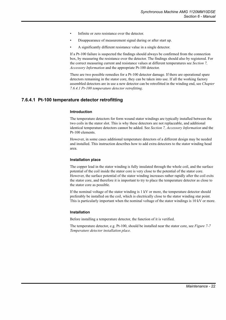
Synchronous Machine AMG 1120MM10DSESection 6 - Manual
Maintenance - 22
• Infinite or zero resistance over the detector.
• Disappearance of measurement signal during or after start up.
• A significantly different resistance value in a single detector.
If a Pt-100 failure is suspected the findings should always be confirmed from the connection box, by measuring the resistance over the detector. The findings should also by registered. For the correct measuring current and resistance values at different temperatures see Section 7, Accessory Information and the appropriate Pt-100 detector.
There are two possible remedies for a Pt-100 detector damage. If there are operational spare detectors remaining in the stator core, they can be taken into use. If all the working factory assembled detectors are in use a new detector can be retrofitted in the winding end, see Chapter 7.6.4.1 Pt-100 temperature detector retrofitting.
7.6.4.1 Pt-100 temperature detector retrofitting
Introduction
The temperature detectors for form wound stator windings are typically installed between the two coils in the stator slot. This is why these detectors are not replaceable, and additional identical temperature detectors cannot be added. See Section 7, Accessory Information and the Pt-100 elements.
However, in some cases additional temperature detectors of a different design may be needed and installed. This instruction describes how to add extra detectors to the stator winding head area.
Installation place
The copper lead in the stator winding is fully insulated through the whole coil, and the surface potential of the coil inside the stator core is very close to the potential of the stator core. However, the surface potential of the stator winding increases rather rapidly after the coil exits the stator core, and therefore it is important to try to place the temperature detector as close to the stator core as possible.
If the nominal voltage of the stator winding is 1 kV or more, the temperature detector should preferably be installed on the coil, which is electrically close to the stator winding star point. This is particularly important when the nominal voltage of the stator windings is 10 kV or more.
Installation
Before installing a temperature detector, the function of it is verified.
The temperature detector, e.g. Pt-100, should be installed near the stator core, see Figure 7-7 Temperature detector installation place.

Synchronous Machine AMG 1120MM10DSESection 6 - Manual
Maintenance - 23
.
Figure 7-7. Temperature detector installation place
Choose a coil of preferred phase, and which is electrically near the stator winding start point.
If the nominal stator voltage is more than 4.2. kV, scratch the red and/or brown surface tape slightly so that the black conductive tape ends, or the grey semiconductive tape start point is visible. Paint a small area, approximately 30 mm with conductive paint. The overlap of the paint with the conducive tape should be at least 5 mm, see Figure 7-8 Conductive painting.
Figure 7-8. Conductive painting
Contact with the winding
A good contact between the coil and the detector is essential when the temperature detector is placed on the stator winding, as the purpose of the temperature detector is to monitor the temperature of the coil, not the surrounding air. Therefore the temperature detector should be placed as close to the coil surface as possible.
The temperature detector should be placed on the coil using silicone padding 10 mm around the detector. The temperature detector is then covered with polyester felt with a total thickness of approximately 6 mm in order to make sure that the detector is not cooled by the ambient airflow. The felt is bound and impregnated using glass or Terylene tape and air-dry polyester or epoxy resin, see Figure 7-9 Temperature detector and cover should be impregnated and bounded tightly.

Synchronous Machine AMG 1120MM10DSESection 6 - Manual
Maintenance - 24
Figure 7-9. Temperature detector and cover should be impregnated and bounded tightly
7.6.5 Insulation resistance measurement for auxiliariesTo ensure correct operation of the machines protections and other auxiliaries, their condition can be determined by an insulation resistance test. The procedure is described in detail in Figure 7.5 Maintenance of stator and rotor winding. The test voltage for the space heater should be 500 VDC and for other auxiliaries 100 VDC. The insulation resistance measurement for Pt-100 detectors is not recommended.
7.6.6 Diode faultIn case any of the diodes in the rotating rectifier should fail, the generator must be tripped. To determine and locate a faulty diode, open the covers at the non-drive end of the machine and measure the insulation resistance with an ohm-meter over one of the diodes. If diode failure is detected, disconnect all diodes and test them separately to locate the faulty diode.
Do not open the service covers or end shields unless it is certain that the machine is isolated from its driving source.
1. Open the service doors at N-end shield of the machine.
2. Disconnect the wires connected to the diodes and exciter winding connection cables. See diode bridge/thyristor bridge drawing in Section 5, Electrical Drawings.
3. Check condition of diodes by measuring resistance over a diode in both directions.
4. Replace the damaged diode(s).
5. Clean the contact surfaces, and apply electric joint compound.
6. Fasten diode(s). Bind the connection leads of the diodes as on original assembly.
7. Check fastening and locking of all rectifier bridge components.
8. Make sure that no tools etc. are inside the machine and close the service covers.
After replacing the diodes, the condition of the diodes can be checked by comparing no-load excitation current to commissioning values. A diode failure results as a significant increase in excitation current.

Synchronous Machine AMG 1120MM10DSESection 6 - Manual
Maintenance - 25
7.7 Maintenance related to thermal performance and cooling systemThere are always two fundamental reasons that might cause an increase in the machine's temperature:
• The effect of the cooling system has declined
• The machine is producing excessive amount of heat
If the machine temperature exceed normal values, measures should be taken to determine which of these two causes is dominant in that particular incident. Excessive heat production might be caused i.e. by a winding problem or by network unbalance and in these cases corrective actions on the cooling system would be ineffective or harmful.
7.7.1 Cooling SystemThe machine is cooled with a shaft mounted fan. The cooling air is taken in from the surroundings through air filters situated at the non-drive end and it is blown out from the top and the sides of the machine at the drive end (IC 0A1). The cooling air should be as clean as possible because the dirt which drifts into the machine causes contamination and reduces the efficiency of the cooling.
The air filters are self charging electrostatic panels of type Pliotron CR. They are constructed of washable, woven polyethylene fiber and incorporate a non-woven synthetic fiber mat. They are enclosed in a rust-resistant galvanized steel-frame and they are reinforced by 1/2" mesh galvanized steel hardware cloth. Their maximum operation temperature is +100°C.
If winding or cooling air temperature detectors show an abnormal temperature, a check of the cooling system has to be made. The two maintenance issues are to check the condition of air filters and to ensure good air circulation inside the machine. The machine interior should be cleaned and checked during overhauls or if problems arise.
Other possible causes for poor cooling system performance might include elevated ambient temperature or high intake air temperature. In addition lubrication or bearing malfunction might lead to high bearing temperature.
A seemingly high temperature might also be caused by a problem in the temperature measurement system, see Chapter 7.6.4 Pt-100 resistance temperature detectors.

Synchronous Machine AMG 1120MM10DSESection 6 - Manual
Maintenance - 26
Figure 7-10. Air cooling
7.7.1.1 CleaningThe filters should be cleaned on an established basis. When the temperature detectors in the winding show abnormal temperature or approach the alarm level, the filters have to be cleaned. If a pressure manometer is used, the filters have to be cleaned when the pressure drop has doubled.
Remove the air filters for cleaning. They should regularly be cleaned by vacuuming first from the upstream side, then on the discharge side. Periodically, a thorough wash with clean water is recommended to release any dirt not removed by vacuuming. When heavy grease concentrations are encountered, the filters should be washed with a detergent solution. This solution should be rinsed thoroughly before returning the filter to service. Be careful to install the air filters back the right side out (arrows on the air filter frame indicate the direction of air flow). Refer also to air filter manufacturer information.
7.8 Maintenance program In this chapter is presented a recommended maintenance program for ABB synchronous machines. This program is general in nature and should be considered as the minimum level of maintenance. Maintenance should be intensified when local conditions are demanding or very high reliability is required. It should also be noted that even when following this maintenance program normal supervision and observation of the machine's condition is required.
Please note that even though we have customized the maintenance program to match your machine, it might contain references to accessories that you do not have.

Synchronous Machine AMG 1120MM10DSESection 6 - Manual
Maintenance - 27
The maintenance program is based on four levels of maintenance, that rotate according to operating hours. The amount of work and down time vary, so that level 1 includes mainly quick visual inspections and level 4 more demanding measurements and replacements. More information about the spare part packages suitable for these maintenances can be found in Chapter 7.9. The recommended maintenance interval can be seen in Table 7-4 Recommended maintenance program (one complete cycle). The operation hour recommendation in this chapter are given as equivalent operating hours (Eq. h), that can be counted by the following formula:
Equivalent operating hours (Eq. h) = Actual operating hours + Number of starts x 20
Level 1 (L1)
Level 1 or L1 maintenance consist of visual inspections and light maintenance. The purpose of this maintenance is to do a quick check whether problems are beginning to develop before they cause failures and unscheduled maintenance breaks. It gives also suggestions what maintenance issues must be performed in the next larger overhaul.
The maintenance can be estimated to last approximately 4 - 8 hours, depending on the type and installation of the machine and the depth of the inspections. Tools for this maintenance include normal servicing tools i.e. wrenches and screw drives. The preparations consists of opening the inspection covers. It is recommended that at least the safety package spare parts are available when commencing this maintenance.
The first Level 1 maintenance should be performed after 4 000 equivalent operating hour or after six months after commissioning. Subsequently the L1 maintenance should be done yearly halfway between Level 2 maintenances.
Level 2 (L2)
Level 2 or L2 maintenance consist mainly of inspections and tests and small maintenance tasks. The purpose of this maintenance is to test whether there are problems in the operation of the machine and to do small repairs to ensure uninterrupted operation.
The maintenance can be estimated to last approximately 8 - 16 hours, depending on the type and installation of the machine and the amount of servicing to be done. Tools for this maintenance include normal servicing tools, multimeter, torque wrench and insulation resistance tester. The preparations consist of opening the inspection covers and bearings if necessary. Spare parts suitable for this level of maintenance are included the maintenance package.
The first Level 2 maintenance should be performed after 8 000 equivalent operating hour or one year after commissioning. Subsequently the L2 maintenance should be done yearly or after every 8 000 equivalent operating hours.
Level 3 (L3)
Level 3 or L3 maintenance consist of performing extensive inspections and tests and larger maintenance tasks that have come up during L1 and L2 maintenances. The purpose of this maintenance is to repair encountered problems and replace parts subjected to wearing.
The maintenance can be estimated to last approximately 16 - 40 hours, depending on the type and installation of the machine and the amount of repairs and replacements to be done. Tools for this maintenance include the same tools as for L2 and in addition a borescope (endoscope) and oscilloscope. The preparations consist of opening the inspection covers, the bearings and the water cooler, if applicable. Spare parts suitable for this level of maintenance are included the maintenance package.

Synchronous Machine AMG 1120MM10DSESection 6 - Manual
Maintenance - 28
The Level 3 maintenance should be performed after every 24 000 equivalent operating hour or at three to five year interval. When a L3 maintenance is conducted it replaces the L1 or L2 maintenance otherwise scheduled and it leaves their rotation unaffected, see Table 7-4 Recommended maintenance program (one complete cycle) for more information.
Level 4 (L4)
Level 4 or L4 maintenance consist of performing extensive inspections and maintenance tasks. The purpose of this maintenance is restore the machine into a reliable operating condition.
The maintenance can be estimated to last approximately 40 - 80 hours, depending mostly on the condition of the machine and the needed reconditioning actions. Tools for this maintenance include the same tools as for L3 and in addition rotor removal equipment. The preparations consist of opening the inspection covers, the bearings and the water cooler, if applicable, and the removal of rotor and exciter.
The amount of spare parts required for this level of maintenance are difficult to determine. At least the maintenance package is recommended, but spare parts included in the capital spare part package would better ensure a fast and successful execution of this maintenance.
The Level 4 maintenance should be performed after every 80 000 equivalent operating hour. When a L4 maintenance is conducted it replaces the L1, L2 or L3 maintenance otherwise scheduled and it leaves their rotation unaffected.
Interval (Eq. h) L1 L2 L3 L4
4000 X
8000 X
12000 X
16000 X
20000 X
24000 X
28000 X
32000 X
36000 X
40000 X
44000 X
48000 X
52000 X
56000 X
60000 X
64000 X
68000 X
72000 X

Synchronous Machine AMG 1120MM10DSESection 6 - Manual
Maintenance - 29
Table 7-4. Recommended maintenance program (one complete cycle)
7.8.1 Recommended maintenance programAbbreviation used in maintenance program:
• V = Visual checking
• C = Cleaning
• D = Disassembling and assembling
• R = Reconditioning or replacement
• T = Testing and measurement
NOTE: All options are not applicable for all machines.
7.8.1.1 General construction
76000 X
80000 X
MAINTENANCE INTERVAL
In equivalent operating hours or time period, which ever comes first
L1 L2 L3 L4
4000 Eq. h 8000 Eq. h 24000 Eq.h 80000 Eq. h
Maintenance object ½ year Annual 3 - 5 years Overhaul Check / Test
Maintenance object L1 L2 L3 L4 Check / Test
Machine operation V/T V/T V/T V/T Starting, shut down, vibration measurement, no-load point
Mounting and foundation V V/T V/T V/T/D Cracks, rust, alingment
Exterior V V V V Rust, leakage, condition
Fastenings V V/T V/T V/T Tightness of all fastenings
Anchor bolts V V V/T V/T Fastening, condition

Synchronous Machine AMG 1120MM10DSESection 6 - Manual
Maintenance - 30
7.8.1.2 High voltage connection
7.8.1.3 Stator and rotor
Maintenance object L1 L2 L3 L4 Check / Test
High voltage cabling V V/T V/T V/T/D Wear, fastening
High voltage connections V V/T V/T V/T/D Oxidation, fastening
Terminal box accessories, i.e. surge capacitors and arresters
V V V V General condition
Cable transits V V V V Condition of cables entering the machine and inside the machine
Maintenance object L1 L2 L3 L4 Check / Test
Stator core V V V V/C Fixing, cracks, welds
Stator winding insulation V V/T V/T/C V/T/C Wear, cleanliness, insulation resistance, turn insulation test, (high voltage test)
Stator coil over hangs V V V V Insulation damages
Stator coil supports V V V V Insulation damages
Stator slot wedges V V V V Movement, tightness
Stator terminal bars V V V V Fixing, insulation
Stator cable terminal fastenings and crimps
V V/T V/T V/T Tightness, condition
Instrumentation V V V V Condtion of cables and cable ties
Rotor poles V V V V Movement, tightness, fixing
Rotor winding insulation V V/T V/T/C V/T/C Wear, cleanliness, insulation resistance, voltage drop test
Rotor coil supports V V V V Movement, bending
Rotor balancing weights V V V V Movement
Damper bars V V/T V/T V/T Cracks, corrosion, ultra sound and knocking test
Shaft and rotor center V V V V Cracks, corrosion
Air gap V V/T V/T V/T/D Equality
Connections in rotor V V V/T V/T Fixing, general condition

Synchronous Machine AMG 1120MM10DSESection 6 - Manual
Maintenance - 31
7.8.1.4 Excitation system, control and protection
Earthing brushes V V V V Operation and general codition
Rotor shaft insulation V V V/T V/T General condition, insulation resistance
Maintenance object L1 L2 L3 L4 Check / Test
Exciter diode bridge V V/T/C V/T/C V/T/C Cleanliness, operation
Exciter semiconductors V V/T/C V/T/C V/T/C Operation, fixing
Excitation connections V V/T/C V/T/C V/T/C Fixing, general condition
Exciter winding insulation
V V/T V/T V/T Wear, cleanliness, insulation resistance
Exciter air gap V V/T V/T/D V/T/D Equality
AVR unit V V/T V/T V/T Operation, settings, stability test
AVR board V V/T V/T V/T Operation, connections
PMG V V V/T V/T Operation, connections
Voltage transformer (VT) V V/T V/T V/T Operation, cleanliness
Short circuit current transformer (CT)
V V V/T V/T Operation, cleanliness
Actual value CT V V V/T V/T Operation, cleanliness
Measurement and protection CTs
V V V/T V/T Operation, cleanliness
Pt-100 elements (stator, cooling air, bearing)
V V/T V/T V/T Resistance, insulation resistance
Anticondensation heaters V V/T V/T V/T Operation, insulation resistance
Auxiliary terminal boxes V V/T V/T V/T General condition, terminals, wiring condition
Exciter stator fixing V V V V General condition, cracks
Maintenance object L1 L2 L3 L4 Check / Test

Synchronous Machine AMG 1120MM10DSESection 6 - Manual
Maintenance - 32
7.8.1.5 Lubrication system and bearings
7.8.1.6 Cooling system
7.9 Spare parts
7.9.1 General considerationsThe machines manufactured by ABB are designed and manufactured to provide reliable and trouble free operation for many years. This requires, however, that the machines are properly maintained and operated. This maintenance includes changing of parts subjected to normal wear.
There is always an inevitable amount of uncertainty related to wearing. The wear rates of these parts vary greatly according to application, environment and particular conditions. Therefore, the condition of these parts should be checked regularly and a sufficient amount of spare parts should be kept in stock. These spares help to minimize down time if the need appears. The extent of the stock should be decided based upon the importance of the application, the availability of the particular spare part and the expertize of the local maintenance personnel.
Maintenance object L1 L2 L3 L4 Check / Test
Bearing assembly V V/T V/T V/T Fixing, general condition
Bearing shells V V V/T/D V/T/D General condition, wear
Seals and gaskets V V V/T/D V/T/D Leakage
Bearing insulation V V/T V/T/D V/T/D Condition, insulation resistance
Lubrication piping V V V/T/D V/T/D Leakege, operation
Lubrication oil V/R V/R V/R V/R Quality, quantity, flow
Oil ring V V V V Operation
Oil flow regulator V V/T V/T V/T/D Operation
Oil tank V V/C V/C V/C Cleanliness, leakage
Jack-up system V V/T V/T V/T Operation
Oil cooler / heater T T T T Oil temperature
Maintenance object L1 L2 L3 L4 Check / Test
Fan(s) V V V V Operation, condition
Filters V/C V/C V/C/R V/C/R Cleanliness, operation
Air ways V V/C V/C V/C Cleanliness, operation

Synchronous Machine AMG 1120MM10DSESection 6 - Manual
Maintenance - 33
7.9.2 Wearing parts subjected to mechanical wearThere is always mechanical wearing when two moving surfaces are in contact with each other. In electrical machines most of the mechanical wearing occurs between the rotating shaft and stationary parts. The bearing parts such as bearing shells and oil rings in sleeve bearings will eventually wear out and need to be replaced, even if correct lubrication is maintained. Other wearing parts include seals, that are in constant contact with the rotating shaft, and the brushes, brush gears and slip rings of the slip ring unit.
The parts listed above are an extensive, but not complete, list of the mechanically wearing parts. These parts have an estimated life span, but as mentioned earlier, their actual durability can vary significantly. For this reason, at least these parts should be kept in stock. It should also be noted that the replacement of these parts, due to normal wearing is not covered by the warranty.
7.9.3 Other wearing partsOther types of wearing occur due to i.e. elevated temperatures, electrical disturbances and chemical reactions. The wearing of the diodes in the rectifier bridge is usually related to abnormal electrical operating conditions. It is usually a slow process, but it is strongly dependent on the operation conditions of the machines and system disturbances.
Air filters, that protect the machine interior from contamination get them selves saturated with air impurities and need to be replaced to ensure the correct operation of the cooling unit and the continuous protection of sensitive machine parts.
The electrical windings of the ABB machines have good protection against wearing, but only if correct maintenance and operating conditions are followed. The correct operating temperature must not be exceeded and the windings must be cleaned from dirt regularly. The winding can also be subjected to accelerated wear due to a number of electrical disturbances.
There are Pt100 temperature detectors located inside the stator core slots and they are impossible to replace. Therefore the ABB practice is to add spare Pt100 detectors in the stator core. These detectors are not be considered as regular spare parts, because they are intended to be used as a replacement in case of a stator Pt100 element failure during commissioning. However, these elements can be taken into use also during operation if the primary detector fails. If even the spare element should fail, the possible corrective action is to add Pt100 elements into the stator winding end. See Chapter 7.6.4.1 Pt-100 temperature detector retrofitting.
7.9.4 Selection of the most suitable spare part packageABB provides three level of ready made spare part packages. The personnel best informed of the machine's operational conditions should select the most suitable package based on criticality of the application and on the financial risk related to the duration of downtime and loss of production.
Safety parts for commissioning and to ensure usability
• These are the most essential spare parts that you should have always available
Maintenance parts for trouble shooting and scheduled maintenance
• These parts enable should be available while doing medium term maintenance. These parts also enable fast recovery in case of failure in the most of the accessories.

Synchronous Machine AMG 1120MM10DSESection 6 - Manual
Maintenance - 34
Capital spare parts to reduce repair time in case of serious damage
• These spare parts are recommended when the machine is a part of an essential processes. These spare parts enable fast recovery even in case of a serious damage.
7.9.5 Typical recommended spare parts in different setsThe following chapters present a general ABB recommendation of the typical spare parts for different packages. To get an offer of specific parts for your machine, please contact ABB After Sales organization.
Please note that even though we have customized the spare part sets to match your machine, they might contain references to accessories that you do not have.
7.9.5.1 Safety package
7.9.5.2 Maintenance package
Spare part Amount
Automatic voltage regulator (AVR) 1 pc.
Rectifier diodes 3 pcs.
Varistor 1 pc.
Air filters Set
Pt-100 for cooling air 1 pc.
Bearing RTD 1 pc.
Bearing labyrinth seal 2 pcs.
Bearing shell, for D-end and NE-end 1 pc.
Bearing oil ring 1 pc.
Spare part Amount
Safety package (without AVR) 1 pc.
AVR with board 1 pc.
Voltage transformer 1 pc.
Short circuit current transformers 3 pcs.
Actual value current transformer 1 pc.
Stator current measurement transformers 3 pcs.
Space heater 1 pc.

Synchronous Machine AMG 1120MM10DSESection 6 - Manual
Maintenance - 35
Capital spare parts
7.9.6 Order informationTo ensure fast and correct spare part ordering and delivery, our After Sales personnel should be provided with at least the type and serial number of the machine in question. This information is given i.e. on the front page of this manual and it can also be found on rating plate fixed to the machine frame. In addition they require specific information about the parts to be ordered. For most parts, this can be found in Section 7, Accessory Information. The contact information of our After Sales organization can be found in Chapter 9, After Sales and Market Support.
Spare part Amount
Exciter rotor 1 pc.
Exciter stator 1 pc.
Rectifier bridge 1 pc.
Rotor pole 2 pcs.
Rotor (complete) 1 pc.
Stator with frame 1 pc.
Water cooler element 1 pc.

Synchronous Machine AMG 1120MM10DSESection 6 - Manual
Maintenance - 36
7.10 TroubleshootingThis chapter is intended to help in the event of an operational failure with ABB delivered machine. The trouble shooting charts given below can assist in locating and repairing mechanical, electrical and thermal problems and problems with lubrication system. The checks and corrective actions mentioned should always be conducted by qualified personnel. If in doubt, ABB After Sales should always be contacted. They can provide more information or technical assistance for trouble shooting and maintenance.

Synchronous Machine AMG 1120MM10DSESection 6 - Manual
Maintenance - 37
7.10.1 Mechanical performance
Troubleshooting
Mechanical performance
Vibr
atio
n
Noi
se
Lubrication malfunction Check lubricant quality and quantity and lubrication system functionDamaged bearing parts Check bearing condition and replace bearing partsFaulty bearing assembly Open and readjust the bearing
Faulty cooling fan(s) Imbalanced or damaged fan(s) Check and repair cooling fan(s)Malfunctioning cooling system Inspect and repair cooling systemMalfunctioning excitation system Inspect and repair excitation systemMachine misalignment Check machine alignmentRotor or shaft imbalance Rebalance rotorLoose parts in rotor Check rotor wedges, poles etc., repair and rebalance rotorVibration coming from connected machinery Check the balance of connected machinery and coupling typeAxial load coming from connected machinery Check alignment and coupling function and typeFaulty or incorrectly assembled coupling Check coupling functionInsufficient foundation strength Reinforce foundation as per ABB instructionsMain machine or excitation machine winding fault Check main machine and excitation machine windingsExcessive network unbalance Check that network balance fulfils requirements Bearing misalignment Check bearing pedestal alignmentForeign material, moisture or dirt inside the machine Check and clean machine interior, dry windingsAirgap not uniform Measure and adjust airgap
Experienced malfunction
Corrective action
Bearing malfunction
Possible cause
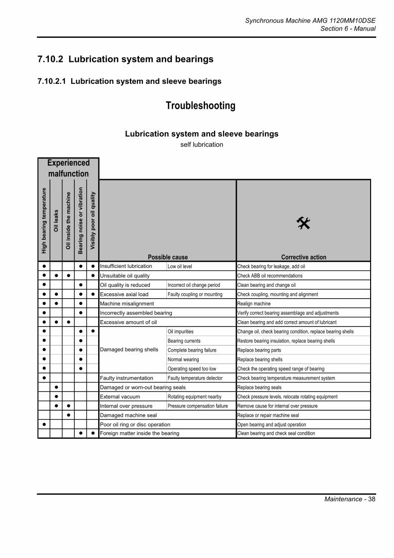
Synchronous Machine AMG 1120MM10DSESection 6 - Manual
Maintenance - 38
7.10.2 Lubrication system and bearings
7.10.2.1 Lubrication system and sleeve bearings
Troubleshooting
Lubrication system and sleeve bearingsself lubrication
Hig
h be
arin
g te
mpe
ratu
re
Oil
leak
s
Oil
insi
de th
e m
achi
ne
Bea
ring
nois
e or
vib
ratio
n
Visi
bly
poor
oil
qual
ity
Insufficient lubrication Low oil level Check bearing for leakage, add oilUnsuitable oil quality Check ABB oil recommendationsOil quality is reduced Incorrect oil change period Clean bearing and change oilExcessive axial load Faulty coupling or mounting Check coupling, mounting and alignmentMachine misalignment Realign machineIncorrectly assembled bearing Verify correct bearing assemblage and adjustmentsExcessive amount of oil Clean bearing and add correct amount of lubricant
Oil impurities Change oil, check bearing condition, replace bearing shellsBearing currents Restore bearing insulation, replace bearing shellsComplete bearing failure Replace bearing partsNormal wearing Replace bearing shellsOperating speed too low Check the operating speed range of bearing
Faulty instrumentation Faulty temperature detector Check bearing temperature measurement systemDamaged or worn-out bearing seals Replace bearing sealsExternal vacuum Rotating equipment nearby Check pressure levels, relocate rotating equipmentInternal over pressure Pressure compensation failure Remove cause for internal over pressureDamaged machine seal Replace or repair machine sealPoor oil ring or disc operation Open bearing and adjust operationForeign matter inside the bearing Clean bearing and check seal condition
Damaged bearing shells
Experienced malfunction
Corrective actionPossible cause

Synchronous Machine AMG 1120MM10DSESection 6 - Manual
Maintenance - 39
7.10.3 Thermal performance
7.10.3.1 Thermal performance, open air cooling system
Troubleshooting
Thermal performanceopen air cooling system
Hig
h w
indi
ng te
mpe
ratu
re
Hig
h co
olin
g ai
r tem
pera
ture
Ambient temperature too high Add ventilation to decrease ambient temperatureExiting air is pulled back in Ensure sufficient clear distances surrounding the machineHeat source nearby Place heat sources further away, check ventilationDirty machine interior Clean machine parts and air gapsFaulty cooling arrangement Inspect cooling arrangement condition and correct assemblyAir intakes are blocked Clear air intakes of debrisAir filter is clogged Clean or replace air filters
Damaged cooling fan(s) Replace fan(s)Cooling fan rotating in the wrong direction Replace fan(s) or change rotating direction of external fanOverload Control system setting Check machine controls, eliminate overloadOverspeed Check actual speed and ABB speed recommendationsNetwork unbalance Check that network balance fulfils requirements Faulty instrumentation or measurement system Check measurements, sensors and wiringMain machine or excitation machine winding fault Check main machine and excitation machine windings
Note:For high bearing temperature see: Trouble shooting, Lubrication system and bearings
Faulty air flow
Experienced malfunction
Possible cause Corrective action
High intake air temperature

Synchronous Machine AMG 1120MM10DSESection 6 - Manual
Maintenance - 40
7.10.4 Electrical performance
Troubleshooting
Electrical performance and excitation system of variable speed motorswith brushless excitation
Exci
tatio
n fa
ilure
Mal
func
tion
durin
g st
artin
g
Perf
orm
ance
dev
iatio
n
Ope
ratio
n no
t adj
usta
ble
Asy
nchr
onou
s op
erat
ion
Faulty drive system Check variable speed equipment and settingFaulty settings Check excitation panel relay and voltage regulator settingFaulty wiring Check connection between excitation panel and motor
Main motor winding fault Check main machine winding and insulation resistancesExcitation field winding fault Check field winding and insulation resistancesExcitation machine winding fault Check excitation machine winding conditionFaulty rotating rectifier Check rectifier component and ignition system conditionsElectrical fault in excitation system Check electrical connections in excitation systemExcitation equipment fault Control cubicle equipment Check and repair excitation equipment in control cubicleEncoder malfunction Check condition of speed and position encoders
Corrective action
Experienced malfunction
Possible cause
Faulty excitation supply unit

Synchronous Machine AMG 1120MM10DSESection 6 - Manual
Maintenance - 41
7.10.4.1 Electrical performance and excitation system of generators
Troubleshooting
Electrical performance and excitation system of generatorswith transformer excitation
Lost
exc
itatio
n
Incr
ease
in e
xcita
tion
curr
ent
Mal
func
tion
durin
g st
art-u
p
Perf
orm
ance
dev
iatio
n
Ope
ratio
n no
t adj
usta
ble
Faul
ty p
aral
lel o
pera
tion
Abnormal speed Faulty speed control Check speed control of operating machineNetwork phase unbalance Check that network balance fulfils requirements Speed variation of operating machine Check speed control of operating machine
Faulty settings Check excitation panel relay and voltage regulator settingFaulty wiring Check excitation panel control cubicle and generatorDemagnetised excitation magnet See main connection diagram to restore permanent magnet excitation
Defective voltage transformer Check transformer winding insulation resistance and connectionsDefective parallel operation transformer Check transformer winding insulation resistance and connectionsDefective current transformer Check transformer winding insulation resistance and connectionsShort circuit excitation system failure Check operation of short circuit excitation systemMain generator winding fault Check main machine winding and insulation resistancesExcitation system winding fault Check exciter winding and insulation resistancesFaulty rotating rectifier Check connection and condition of rectifier componentsFaulty wiring in excitation system Check electrical connections in excitation systemExcitation equipment fault Excitation panel equipment Check and replace excitation panel equipmentFaulty AVR settings Check and adjust voltage regulator settingsBad AVR tuning parameters Voltage oscillation, poor response Check AVR tuning (PID parameters)Defective AVR Check and replace voltage regulatorFaulty AVR wiring or incorrect connections Check AVR wiring and connectionsPower factor variation over permitted values Check AVR conditionFaulty external voltage reference system Check connections and condition of voltage reference No actual value information for AVR Check actual value measurement system and electrical connections
Note:AVR = Automatic Voltage Regulator
Field application failure
Experienced malfunction
Possible Cause Corrective action

Synchronous Machine AMG 1120MM10DSESection 6 - Manual
Dismantling and Reassembly - 1
Chapter 8 Dismantling and Reassembly
8.1 GeneralFor complete overhaul, cleaning and possible revarnishing, the machine must be dismantled so that the rotor and the stator are separated.
How often a thorough cleaning should be made can be judged from the state of uncleanness observed in the annual inspections. If the machine is not subjected to more than normal contamination, an inspection interval of five to ten years is recommended.
8.2 Preparation for dismantlingObserve that most of the inspection and maintenance work can be done after removing the covers, and by using the existing maintenance doors and air intake and outlet openings. Ensure that there is no risk of electrical or mechanical accident. The machine should be electrically, and if necessary mechanically disconnected, and earthed.
Main supply cables or busbars and auxiliary cables should be disconnected and identified for reconnection. All necessary safety precautions should be taken. The complete machine should if possible be removed from its site to a dry and dust-free location.
Shims placed under the feet of the machine as well as dowel pins should be identified and retained for later reassembly. Shaft coupling halves should be marked.
8.3 DismantlingConstruction drawings of the machine and the bearings should be used to guide the dismantling work, see Section 4 Mechanical Drawings, and Section 5 Electrical Drawings.
Remove the side covers. Turn the shaft into a position where it can firmly rest on the stator laminations. Push strong plywood pieces into the air gap under the rotor from the N-end, see Figure 8-1 Plywood pieces supporting the rotor. Where applicable, also put pieces of strong plywood between the exciter rotor and stator. Dismount the instruments, the seals and the bearing housing upper parts.
Tighten the two end shield jacking screws on both ends of the machine, and then remove the end shield dowel pins. Loosen the end shield fixing bolts until the jacking screws carry the weight of the rotor, the bearings and the end shields. Remove all end shield-fixing bolts except two on both sides of the bearing. Turn the jacking screws counter-clockwise until the rotor is supported by the plywood pieces previously inserted between the rotor and the stator. Direct contact between stator and rotor must be avoided.
Remove the upper part of the bearing shells and the oil rings. Loosen the end shield jacking screws until the bearing shell moves easily. Turn the shell 180° over the shaft and remove it. Remove the N-end end shield with the exciter stator and the bearing housing by moving it carefully along the axis of the rotor. Use a crane and an additional tackle to balance the end shield as to avoid damaging the exciter windings. Dismount the D-end bearing housing. On some cases the rotor must be moved 10 mm towards D-end to remove the D-end bearing housing. This is carried out by using the same principle as when the rotor is removed out of the stator. Remove the D-end end shield by moving it carefully along the rotor axis towards the D-end. Where applicable, remove the fan.

Synchronous Machine AMG 1120MM10DSESection 6 - Manual
Dismantling and Reassembly - 2
When removing the rotor from the stator, a special piece of tubing is used for elongation of the shaft. Great care should be taken in order not to scratch or otherwise damage the windings.
Figure 8-1 Plywood pieces supporting the rotor
8.4 Removing the rotorA special extension shaft is fitted to the end of the rotor. The rotor is supported from the end of the extension shaft and the other end of the rotor.
The rotor is carefully moved outward. When the center of gravity of the rotor is outside the stator frame, move the support from the end of the extension shaft next to the center of gravity of the rotor.
Move the rest of the rotor carefully out from the stator frame. If there is not enough space to remove the rotor directly out, it can be turned to either side. Great care has to be taken in order not to damage the windings, see Figure 8-2 Typical rotor removal procedure and Figure 8-3 Typical rotor removal procedure (continued).
PLYWOOD PIECES

Synchronous Machine AMG 1120MM10DSESection 6 - Manual
Dismantling and Reassembly - 3
Figure 8-2 Typical rotor removal procedure

Synchronous Machine AMG 1120MM10DSESection 6 - Manual
Dismantling and Reassembly - 4
Figure 8-3 Typical rotor removal procedure (continued)
8.5 Reassembly and RealignmentFor reassembly and realignment work the same instructions are generally valid as for original assembly and alignment work. Construction drawings and special mounting instructions should be employed.
When reassembling the covers, air ducts and terminal boxes, the gaskets should be examined and renewed if necessary.
8.6 Stator Shift
IntroductionIt is normally not necessary to remove the rotor from a synchronous machine. However, if a need to remove or inspect the rotor turns up, it can for instance be done by stator shift. This method requires a minimum of equipment.

Synchronous Machine AMG 1120MM10DSESection 6 - Manual
Dismantling and Reassembly - 5
Stator Shift Procedure
1. Temporarily remove the electrical and mechanical connections
2. Open the coupling between the synchronous machine, and the driving/driven machine
3. Add additional frame at the non-drive end of the common frame
4. Slide the synchronous machine away from the driving/driven machine
5. Support the rotor inside the stator core
6. Remove coupling half, bearings, end shields, exciter stator and fan
7. Add extension shaft in drive end
8. Support extension shaft and rotor on additional supports
9. Slide synchronous machine towards driving/driven machine
InspectionThe complete synchronous machine can now be inspected, or dismantled if required. The rotor can be removed by the use of only one crane.
Reassembly of Synchronous MachineIn order to reassemble the synchronous machine, the stator shift procedure is reversed.

Synchronous Machine AMG 1120MM10DSESection 6 - Manual
After Sales and Market Support - 1
Chapter 9 After Sales and Market Support
After Sales and Market Support for Rotating Electrical Machines manufactured by ABB , and Strömberg in Helsinki, Finland since 1889.
Site Services and Spare PartsProvides commissioning and erection supervision, co-ordinates spare parts packages delivered with the machine, sells spare parts after the delivery of the machine.
WarrantiesManages complaints and warranty questions concerning the machines.
Support for Service CentersSupports in questions concerning the mechanical construction as well as in electromagnetic and insulation technology issues.
Contact the After Sales department by:
• Phone 7:00 am - 5:30 pm (GMT+2) +358 (0)10 22 2000
• Fax +358 (0)10 22 22544
• e-mail [email protected]
• 24 hour emergency service +358 (0)10 22 21999

User’s Manual
Serial no.ABB ref.Project:
ABB
Synchronous MachineAMG 1120MM10DSE
45771693020HE401
July 2004 Grupo Punta Cana
7.AccessoryInformation

User’s Manual
Serial no.ABB ref.Project:
ABB
ContentsAccessory Information
Delivered with Machine
Resistance Temperature Detector -PYR_L_/_..........................................................1
Resistance Temperature Detector - PYR_R_0_ ........................................................4
Anti-condensation Heater RER 800/490 V .......6
Pliotron CR Air Filter .........................................8
Voltage Transformer T1 type 3PU180/63/E....11
Current Transformer T2 KSG..........................15
Current Transformer T3 IFJ-3 Arteche............18
Current Transformer T4 ACI-17 Arteche.........20
Silicon Diode LNM SKKD 260/20....................22
Varistor Module SXV 40K550 C......................23
Roxtec Cable Glands ......................................25
Excitation Current Limiter ECL-10 ..................29
UNITROL 1000 AVR Instruction Manual
Bearing Documentation by Renk AG
Other Documentation
Synchronous MachineAMG 1120MM10DSE
45771693020HE401
July 2004 Grupo Punta Cana
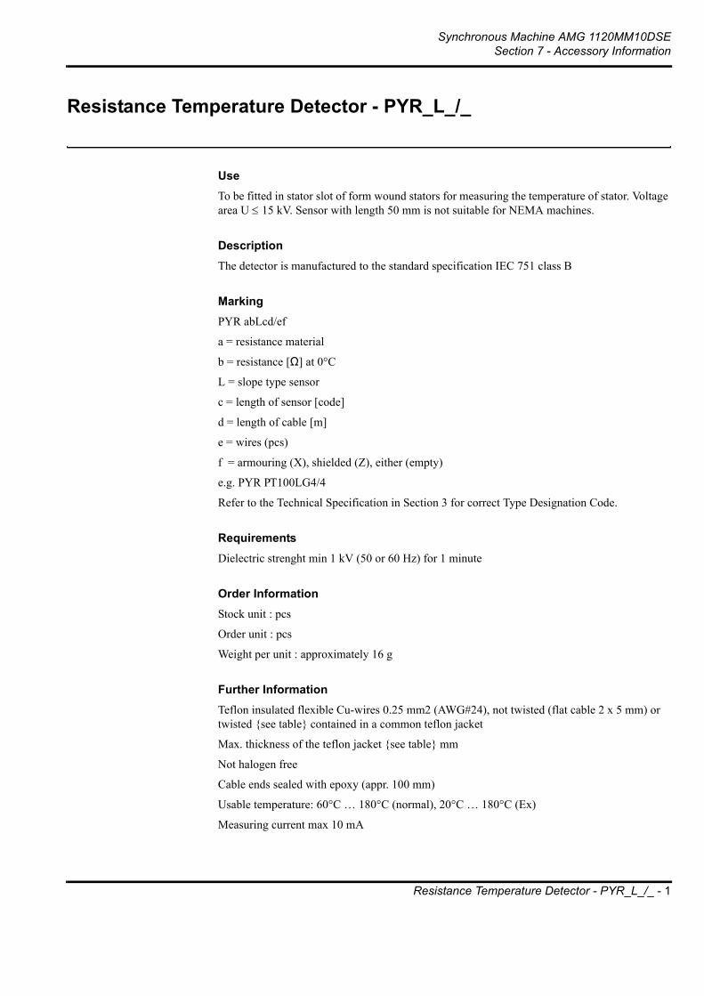
Synchronous Machine AMG 1120MM10DSESection 7 - Accessory Information
Resistance Temperature Detector - PYR_L_/_ - 1
Resistance Temperature Detector - PYR_L_/_
UseTo be fitted in stator slot of form wound stators for measuring the temperature of stator. Voltage area U ≤ 15 kV. Sensor with length 50 mm is not suitable for NEMA machines.
DescriptionThe detector is manufactured to the standard specification IEC 751 class B
MarkingPYR abLcd/ef
a = resistance material
b = resistance [Ω] at 0°C
L = slope type sensor
c = length of sensor [code]
d = length of cable [m]
e = wires (pcs)
f = armouring (X), shielded (Z), either (empty)
e.g. PYR PT100LG4/4
Refer to the Technical Specification in Section 3 for correct Type Designation Code.
RequirementsDielectric strenght min 1 kV (50 or 60 Hz) for 1 minute
Order InformationStock unit : pcs
Order unit : pcs
Weight per unit : approximately 16 g
Further InformationTeflon insulated flexible Cu-wires 0.25 mm2 (AWG#24), not twisted (flat cable 2 x 5 mm) or twisted see table contained in a common teflon jacket
Max. thickness of the teflon jacket see table mm
Not halogen free
Cable ends sealed with epoxy (appr. 100 mm)
Usable temperature: 60°C … 180°C (normal), 20°C … 180°C (Ex)
Measuring current max 10 mA

Synchronous Machine AMG 1120MM10DSESection 7 - Accessory Information
Resistance Temperature Detector - PYR_L_/_ - 2
Code Type designation Dielectricstrenght[kV]
Twistedwire
Ø[mm]
L1[mm]
L2[mm]
Ex approved[EEx e II]
9872265 PYR PT1000LC3/4 5 No 2 3000 50 -
6013601 PYR PT100LC3/4EX 5 No 2 3000 50 PTB Nr: Ex-87.D.2021UKEMA Nr: Ex-96.D.1529U
6017515 PYR PT100LG4/4EX 5 No 2 4000 200 PTB Nr: Ex-96.D.3139UKEMA Nr: Ex-96.D.1529U
9872735 PYR PT100LG4/4Z 3,2 Yes 3 4000 200 -
9872555 PYR PT120LG4/4 5 No 2 4000 200 -
9872546 PYR PT1000LG4/4 5 No 2 4000 200 -
9872557 PYR CU10LG4/4 5 No 2 4000 200 -
9872556 PYR NI120LG4/4 5 No 2 4000 200 -
6004202 PYR PT100LG7/3 3,2 Yes 2,8 7000 200 -
9874084 PYR PT100LG7/2Z 3,2 Yes 3 7000 200
9870614 PYR PT100LG7/3EX 3,2 Yes 2,8 7000 200PTB Nr: Ex-87.D.2021UPTB Nr: Ex-97.D.2239UKEMA Nr: Ex-96.D.1529U
9872008 PYR PT100LG18/3 3,2 Yes 2,8 18000 200 -

Synchronous Machine AMG 1120MM10DSESection 7 - Accessory Information
Resistance Temperature Detector - PYR_L_/_ - 3
Figure 1. Sensor with cable without armouring
Figure 2. Sensor with shielded cable

Synchronous Machine AMG 1120MM10DSESection 7 - Accessory Information
Resistance Temperature Detector - PYR_R_0/_ - 4
Resistance Temperature Detector - PYR_R_0/_
UseTo be fitted in the shell of sleeve bearings for measuring the temperature of the bearing. Used also in controlling the temperature of the cooling air.
DescriptionThe detector is manufactured to the standard specification IEC 751 class B
MarkingPYR abcRd0/e
a = number of the detectors
= 1 detector
2 = 2 detectors
b = resistance material (PT = platinum)
c = resistance (Ω) at 0°C
d = length code of the detector
e = number of the wires
Refer to the Technical Specification in Section 3 for correct Type Designation Code.
RequirementsDielectric strength min 1 kV ( 50 or 60 Hz ) for 1 minute
Degree of protection IP54
Order InformationStock unit : pcs
Order unit : pcs
Further InformationUsable temperature -60°C …+180°C
Small terminal head, DIN 43 729 Form P
Big terminal head, DIN 43 729 Form B
Measuring current max 10 mA

Synchronous Machine AMG 1120MM10DSESection 7 - Accessory Information
Resistance Temperature Detector - PYR_R_0/_ - 5
Code Marking Form L1/mm L2/mmmax.
H1/mm H2/mm Weight/g T
9873253 PYR PT100RC0/4 P 50 55 25 30 210 Pg 9
9873692 PYR 2PT100RC0/4 B 50 85 38 49 260 Pg 16
60129126 PYR PT100RG0/4 P 200 55 25 30 213 Pg 9
99869699 PYR 2PT100RG0/4 B 200 85 38 49 263 Pg 16
99869697 PYR 2PT100RG0/2 P 200 55 25 30 213 Pg 9
60129134 PYR PT100RJ0/4 P 300 55 25 30 220 Pg 9
99869698 PYR 2PT100RJ0/4 B 300 85 38 49 270 Pg 16
99869696 PYR 2PT100RJ0/2 P 300 55 25 30 220 Pg 9
9870430 PYR PT100RL0/4 P 400 55 25 30 280 Pg 9
9870431 PYR PT100RP0/4 P 550 55 25 30 300 Pg 9

Synchronous Machine AMG 1120MM10DSESection 7 - Accessory Information
Tubular Heating Element 800W/490V - 6
Tubular Heating Element 800W/490V
MarkingRER 1-a/b(a = nominal power, b = nominal voltage).
UseAs a standstill heating element for AM_ synchronous machines.
Specification
Technical requirements• Material of the tubular heating element: AISI 304.
• Material of the attachment ear: AISI 304.
• Operating temperature of the connection cables: 100° C.
• Operating voltage of the connection cables: 500 V.
• Cross section area of the connection cables: 1.0 - 2.0 mm2.
• Connection of the connection cables with a connecting clamp: 6.3.
• Halogenous free connection cables.
• Test voltage: 1500 VAC.
Further InformationInformation stamped on the tube of the heating element: Manufacturer, power, voltage, manufacturing number, mont and year of manufacture.
Order related informationStock unit: pcs
Order unit: pcs
Weight per unit: 1.0 kg
Code Type Nom. power [W] Power [W] Nominal voltage[V] Voltage [V]
9871212 RER 1-800W/115V 800 720-870 115 110-120
9871213 RER 1-800W/235V 800 700-900 235 220-250
9871214 RER 1-800W/400V 800 720-970 400 380-440
9871215 RER 1-800W/490V 800 760-840 490 480-500

Synchronous Machine AMG 1120MM10DSESection 7 - Accessory Information
Tubular Heating Element 800W/490V - 7

Synchronous Machine AMG 1120MM10DSESection 7 - Accessory Information
Pliotron CR Air Filter - 8
Pliotron CR Air Filter
PurposePliotron CR Air Filters are designed to remove atmospheric dust including sub-visible particles down to the particle range of 10 microns and less. Sub-visible particles are the predominant cause of extended surface soilage as well as dirt generated electrical circuitry failure.
DescriptionThe Pliotron CR (Commercial/Residential) is a permanent, self charging, electrostatic panel air filter. It is contructed of washable, woven polyethylene fibre and incorporates a non-woven, synthetic fibre mat, both of which are enclosed in a rust resistant, galvanized steel frame and reinforced by 0.5’’ mesh galvanized steel hardware cloth. The filter can withstand temperatures up to 100ºC (212ºF). The polyethylene media is chemically inert to the majority of contaminants encountered in ventilation systems.

Synchronous Machine AMG 1120MM10DSESection 7 - Accessory Information
Pliotron CR Air Filter - 9
Principle of OperationPolyethylene, a high-dielectric plastic, has an inherent capability to generate both positive and negative surface charges in close proximity. Residual surface charges are always present on polyethylene, and combined with the frictional forces of an air stream substantially increases the voltage of these charges. As no external electrical energy is required, polyethylene can be considered as self charging.
As airborne dust particles are of either positive or negative charge, they are both attracted and retained by the opposite charges on the filter media. This electro-static arresting greatly enhances the normal mechanical action of the filter.
MaintenanceThe filter should be cleaned on an established regular basis to obtain maximum efficiency ensuring longer life and long term low running costs.
The filter may be cleaned either by simply using a vacuum, firstly on the upstream side, then repeated on the discharge side. This will assist in maintaining peak performance. Periodically (to be established and maintained) a thorough flush through with clean water, either by immersion or with a fine spray in the opposite direction to the air flow. If contaminated by oily or greasy substances, a detergent solution should be used, after which the filter must be rinsed with clean water.
MarkingWJFA a x b x c
a=width (mm)
b=length (mm)
c=thickness (mm)
(e.g. WJFA 500 x 725 x 24)
Specification
Code Net face velocity m/s
Pressure loss Pa
Airflow m3/s
Net area of filter m2
A B
88319206 3 98 0.300 0.10 245 500
10209072 3 98 0.600 0.20 375 625
88157001 3 98 0.511 0.17 400 500
88319605 3 98 0.631 0.21 400 625
10209510 3 98 0.811 0.27 425 725
10209013 3 98 0.811 0.27 500 625
10208181 3 98 0.961 0.32 500 725

Synchronous Machine AMG 1120MM10DSESection 7 - Accessory Information
Pliotron CR Air Filter - 10
Order related informationAirfilter PLIOTRON CR, Width (a) x Length (b) x Thickness (c). This factory standard must be attached to the order.
Stock unit: pcsOrder unit pcs
DesignationCR

Synchronous Machine AMG 1120MM10DSESection 7 - Accessory Information
Voltage Transformer T1 type 3PU180/63/E - 11
Voltage Transformer T1 type 3PU180/63/E
TECHNICAL DATA FOR VOLTAGE TRANSFORMER T1Three phase voltage transformer for excitation power and to measure actual voltage of synchronous generator. Required one for each generator.
Primary windingVoltage: Un V / Fn Hz
Connection: Y
Terminal marking: A , B , C
Insulation level: Test voltage (winding to case) (2 x Un + 3 kV) x 1.15
Cables 1.5 mm2, L = 2.5 m, tightly fitted silicone insulation 5 mm for Ux < 11.6 kV, 7 mm for Ux > 11.5 kV
Distance between connection cables and case and between individual cables > 30 mm
1st secondary windingVoltage: u1 V
Output: S1 = 3.2 kVA continuously , 5.5 kVA 2 min
Connection : yn0
Terminal marking: a , b , c ,F11
Insulation level: Test voltage 2.5 kV / 50 Hz / 1 min
Terminals are provided with short circuit breaker:
• main contacts: 25 A, when 110 V type S 260-B 25 (ABB Stotz), breaking capacity 6 kA
• main contacts: 16 A, when 165 V type S 260-B 16, breaking capacity 6 kA
• auxiliary contacts: NO+NC type S2-H11
• cable: 2.5 mm2, length 2.5 m. If generator frame size is 1250, 1600 or 2000, length 6.0 m (marked in order)
2nd secondary windingVoltage: u2 V
Output: S2 = 300 VA continuously
Connection : yn0
Terminal marking: 2a , 2b , 2c ,F12
Insulation level: Test voltage 2.5 kV / 50 Hz / 1 min
Terminals are provided with short circuit breaker:
• main contacts: 2 A type S 263-C 2 (ABB Stotz), breaking capacity 6 kA
• auxiliary contacts: NO+NC type S2-H11

Synchronous Machine AMG 1120MM10DSESection 7 - Accessory Information
Voltage Transformer T1 type 3PU180/63/E - 12
• cable: 2.5 mm2, length 2.5 m. If generator frame size is 1250, 1600 or 2000, length 6.0 m (marked in order)
Rating of auxiliary contactsVDE 0660
Ith = 25 A, IGr C /≈ 500 V
AC11 Ue/Ie 415 V / 2 A, 240 V / 6 A
DC11 Ue/Ie 250 V / 1 A, 110 V / 1.5 A, 60 V / 2 A, 24 V / 4 A
Environmental limitsVibration: amplitude 0-peak 0.8 mm, when f ≤ 8 Hz
speed Veff 30 mm/s, when 8 < f < 100 Hz
acceleration 2.5 g, when f ≥ 100 Hz
shock 5 g
Operation temperature: 0 - 60 °C
Storage temperature: -30 - +75 °C
Humidity: 95 % / +40 °C
Further dataProtection class: IP-00
Temperature rise: B-class
Weight: 78 kg
ORDER INFORMATIONVoltage transformer T1, type 3 PU 180/63/E according to this standard and to the order-specific information given in the order form.

Synchronous Machine AMG 1120MM10DSESection 7 - Accessory Information
Voltage Transformer T1 type 3PU180/63/E - 13

Synchronous Machine AMG 1120MM10DSESection 7 - Accessory Information
Voltage Transformer T1 type 3PU180/63/E - 14

Synchronous Machine AMG 1120MM10DSESection 7 - Accessory Information
Current Transformer T2 KSG - 15
Current Transformer T2 KSG
UseNormal use for current sensing for AVR.
MarkingKSG Ipn T2
Ipn = primary current (A)
Refer to the Technical Specification in section 3 for correct Type Designation Code.
SpecificationInsulation level: 1/6/ - kV
Terminal marking: P1, P2, S1, S2
Frequency: 50 - 60 Hz
Primary currents, see table: Ipn
Rated thermal current: Ext. = 120%
Short-time withstand current Ith 1s: 60 * Ipn
Peak withstand current Idyn: 2.5 * Ith
Secondary current: Isn = 1 A
Accuracy class: 0.5
Burden, see table
Operating temperature range: -30°C ... +60°C
Window: 70 mm
Screw of secondary terminal: M5
Weight approximately: 2.5 kg
Delivery without foot and terminal cover
Dimension according to enclosed drawing

Synchronous Machine AMG 1120MM10DSESection 7 - Accessory Information
Current Transformer T2 KSG - 16
Requirements
Code Type Primary current A Rated burden VA
9872221 KSG 0100T2 100 3
9872222 KSG 0125T2 125 4
9872223 KSG 0150T2 150 4
9872224 KSG 0200T2 200 4
9872225 KSG 0250T2 250 5
9872226 KSG 0300T2 300 5
9872227 KSG 0400T2 400 5
9872228 KSG 0500T2 500 5
9872229 KSG 0600T2 600 5
9872230 KSG 0800T2 800 5
9872231 KSG 1000T2 1000 5
9872232 KSG 1250T2 1250 5
9872233 KSG 1500T2 1500 5
9872234 KSG 2000T2 2000 5

Synchronous Machine AMG 1120MM10DSESection 7 - Accessory Information
Current Transformer T2 KSG - 17
Typical Dimensions
Connection

Synchronous Machine AMG 1120MM10DSESection 7 - Accessory Information
Current Transformer T3IFJ-3 Arteche - 18
Current Transformer T3IFJ-3 Arteche
UseExcitation power during generator short circuit. 3 pcs / each generator.
MarkingKSG IFJ- IpnT3 Arteche
SpecificationStandard: IEC 185
Insulation level: 1/6/ - kV
Terminal marking: P1, P2, S1, S2
Rated thermal current: Ext. = 120%
Short-time withstand current Ith 1s: 60 * Ipn
Peak withstand current Idyn: 2.5 * Ith
Operating temperature range: -30°C ... +60°C
Window: 70 mm
Screw of secondary terminal: M5
Delivery without foot and terminal cover
Dimension according to enclosed drawing

Synchronous Machine AMG 1120MM10DSESection 7 - Accessory Information
Current Transformer T3IFJ-3 Arteche - 19

Synchronous Machine AMG 1120MM10DSESection 7 - Accessory Information
Current Transformer ACI-17 Arteche - 20
Current Transformer ACI-17 Arteche
DescriptionThe primary winding of the transformer are encapsulated in cast-resin.
Order specifications:- Quantity
- Type
- System voltage
- Frequancy
- Rated primary and secondary current
- Short time currents Ith (1 sec.) and Idyn
- Rated burden and accuracy class for each core
- Ambient temperature other than IEC (-5 °C...+60 °C)
- Special requirements, if any
- Test report, if required, language specified
Environment:The ACI transformers are made for indoor mounting. The transformers must be protected against unusually heavy deposits of dust or similar pollution, as well as against direct sunshine. See technical specification in Section 3 of this manual for details.

Synchronous Machine AMG 1120MM10DSESection 7 - Accessory Information
Current Transformer ACI-17 Arteche - 21

Synchronous Machine AMG 1120MM10DSESection 7 - Accessory Information
Silicon Diode LNM SKKD 260/20 - 22
Silicon Diode LNM SKKD 260/20
Power Semiconductor Module
MarkingLNM SKKD260/20
OrderPower semiconductor module, isolated metal base. Semipack LNM SKKD 260/20.
Further informationIF(AV) = 260 A, IF max = 410 A, VRMM = 2200 V
Isolation 2500 V AC
Weight per unit 0.9 kg
UseFor rotating rectifier of a synchronous machine.

Synchronous Machine AMG 1120MM10DSESection 7 - Accessory Information
Varistor Module SXV 40K550 C - 23
Varistor Module SXV 40K550 C
Marking:SXV 40K550 C
Purpose:For rotating rectifier of a synchronous machine.
Specification:Varistor
Type: LS40K550QPK2
Marking: VRMS 550 V, VDC 745V, Imax (8/20) µs 40000 A
Manufacturer: Siemens
Capacitor
Type: MKP
Marking: 0,1 µF +-10%. 600Vac, 100 Vdc
Manufacturer: Fischer & Tausche
Box
Type: SKB 33
Manufacturer: Semikron Oy
Teflon FEP-insulated cable
Type: 25303 – 14/19 VA, 1,941 mm2, length: 250 mm and 500 mm
Manufacturer: Teflontalo Irpala Oy
Further information:• Varistor module and capacitor in parallel
• Polarity does not matter
• Can be connected between + and – poles in both directions
• Connection diagram shall be fixed on the module
Order information:Design unit : pcs
Order unit : pcs
Weight per unit : 0.18 kg

Synchronous Machine AMG 1120MM10DSESection 7 - Accessory Information
Varistor Module SXV 40K550 C - 24

Synchronous Machine AMG 1120MM10DSESection 7 - Accessory Information
Roxtec Cable Glands - 25
Roxtec Cable Glands
Assembly instructions - using ROX Wedge
1. Remove any dirt inside the frame.
2. Lubricate the inside faces of the frame.
3. Adapt those modules which are to hold cables or pipes by peeling off layers. Try to achieve a 0-1 mm gap between the two halves when held against the cable/pipe.
4. Lubricate the modules thoroughly with ROX lubricant, both the inside and outside faces.
5. Insert the modules according to your transit plan. Start with the largest modules.
6. Insert a stayplate on top of every finished row of modules.
7. Continue to fill the packing space with cables, modules and stayplates
8. Before inserting the final row of modules, insert two stayplates
9. Separate the two stayplates.
10. Insert the final row of modules between the stayplates.
11. Tip: Put the last two modules together like a "∧" and insert with the point first between the other modules.

Synchronous Machine AMG 1120MM10DSESection 7 - Accessory Information
Roxtec Cable Glands - 26
12. Drop the upper stayplate on top of the modules.
13. Lubricate and insert the ROX Wedge in top of the frame (standard position).
14. Tighten the bolts until stop (max. 20 Nm).
15. Tip: An additional row of RM 10/0 (below the last stayplate) increases the compression in the frame.
16. Optional: The wedge can be inserted in the middle or bottom of the frame. Be sure to place a stayplate only on the marked side of the wedge.
Assembly instructions - using RoxkitFirst follow above steps 1-7.
17. Lubricate and insert the compression plate directly over the final row of modules (no stayplate). Tighten the compression plate bolt until the top-packing fits in.
18. Lubricate and insert the top-packing's middle piece around the bolt.
19. Turn the middle piece 180º.
20. Lubricate and insert the top-packing.
21-22. Tighten the nuts of the top-packing until 10-15 mm of thread protrudes from the nuts.

Synchronous Machine AMG 1120MM10DSESection 7 - Accessory Information
Roxtec Cable Glands - 27
Assembly instructions for R round frames
23. Push the front fittings of the frame to the sides and lubricate the inside of the frame.
24. Adjust, lubricate and insert the modules according to your transit plan.
25. Pull the fittings back towards the centre of the frame and tighten the nuts until approx. 15 mm of thread protrudes.
Assembly instructions - for RS round single penetrations
26. Adjust the centre core of the RS seal to fit the cable by peeling off layers.
27. Lubricate the contact faces between the two transit halves and also the face of the last upper sheet of the core.
28. Insert the two halves into the hole around the cable. Tighten the bolts on the fittings until a seal is achieved.
Disassembly - reopening a ROX wedge transit
29. Turn the two bolts counterclockwise and the ROX Wedge releases itself.
30. Now simply remove the wedge.
31. Lift the upper stayplate.
32. Use fingers or a screwdriver to make the modules come loose. Remove the modules.

Synchronous Machine AMG 1120MM10DSESection 7 - Accessory Information
Roxtec Cable Glands - 28
33. Remove the two stayplates.
34. Now you can route new cables, adapt modules and reassemble the transit.
Using the ROX Top-packing puller
35. Remove the nuts and the front fittings from the top-packing. Turn the inner larger nuts of the puller counterclockwise until they are fairly close to the smaller outer bolts.
36. With its crossbar pointing down attach the puller to the two bolts of the top-packing. Try to attach evenly to the two bolts.
37. When firmly attached turn any of the two larger nuts on the puller in clockwise direction . The top-packing will now start to pull out from the frame.

Synchronous Machine AMG 1120MM10DSESection 7 - Accessory Information
Excitation Current Limiter ECL-10 - 29
Excitation Current Limiter ECL-10

Synchronous Machine AMG 1120MM10DSESection 7 - Accessory Information
Excitation Current Limiter ECL-10 - 30
1 Principle of the excitation current limiter
Figure 1-1 presents a case of generator line short circuit. The redundant current transformers T3 supply during the short circuit excitation power. The ceiling value of excitation current is limited by an excitation current limiter. The limiter consists of a filter, two triggers and four thyristors.
The filter damps high voltage peaks induced due to the combination of current transformer and rectifier. The trigger triggs the associated thyristor, when the voltage between lines intends to exceed a preset level. Thus the current Im through the exciter field remains at constant ceiling value (Figure 1-2, line 3).
The desired trigger value is selected by means of jumpers.The curves 1a and 1b present currents supplied by ct’s T3 in cold and warm conditions, respectively.
Figure 1-1

Synchronous Machine AMG 1120MM10DSESection 7 - Accessory Information
Excitation Current Limiter ECL-10 - 31
Figure 1-2
2 Specification
2.1 DescriptionThe ECL-10 is inteded to limit excitation current in case of a synchronous generator output is shorted. It is recommended to mount on a AVR mounting plate.
During normal operation the ecitation current limiter has no role in the excitation system, because its terminals are shorted.
The operation of ECL-10 will take place only occasinally and with duration of few seconds in case of generator short circuit, when the line voltage is dropped somewhere below 80% of the rated value. This level is determined by an AVR or some other device.
2.2 InputsThere are three input terminals: L1, L2, L3. Screw connectors 4 mm2.
The terminals should be connected between the cables from the current transformers T3.
Max. 3-ph voltage 230 V / 10 sec.
2.3 Settings The trigger level is set by means of jumpers. Therefore there are 10 screws, each 4 mm2. See Chapter 3 Trigger setting.
2.4 Ambient values Operating temperature 0 …. 60 oC
Relative humidity max. 90 %

Synchronous Machine AMG 1120MM10DSESection 7 - Accessory Information
Excitation Current Limiter ECL-10 - 32
2.5 Mechanical dataWeight: 700 g
Protection class: IP20
Bottom mounting with two M6 screws.
3 Trigger setting
Sustained short circuit current in line shall exceed a certain level in order to ensure a appropriate over current relay function. On the other hand excessive line current in a case of short circuit may destroy the generator.
That’s why there is a max limit for short circuit current as well. In general the desired short ciruit current is approximately 3,5 * rated current.
To find the right position for jumper setting, it is needed to carry a couple of short circuit tests with generator .
The default position bases on the rated excitation voltage Um. Ummax is approx. 1,4 * Um. So in the table below you select the assosiated setting on the same line with the Ummax. ***)

Synchronous Machine AMG 1120MM10DSESection 7 - Accessory Information
Excitation Current Limiter ECL-10 - 33
***) Ummax values are as yet preliminary
TRIGGER SETTING FOR ECL-10A - trigger B - trigger Ummax
Pos T e r m i n a l s T e r m i n a l s approx.
4 - 5 5 - 6 6 - 7 7 - 8 9-10 10-11 11-12 12-13 V*) *) *) *) *) *) *) *) **)
1 C C C C C C C C 752 C C C C C C C Open 813 C C C Open C C C Open 864 C C C Open C C Open C 925 C C Open C C C Open C 976 C C Open C C C Open Open 1037 C C Open Open C C Open Open 1088 C C Open Open C Open C C 1149 C Open C C C Open C C 119
10 C Open C C C Open C Open 12511 C Open C Open C Open C Open 13012 C Open C Open C Open Open C 13613 C Open Open C C Open Open C 14114 C Open Open C C Open Open Open 14715 C Open Open Open C Open Open Open 15216 C Open Open Open Open C C C 15817 Open C C C Open C C C 16318 Open C C C Open C C Open 16919 Open C C Open Open C C Open 17420 Open C C Open Open C Open C 18021 Open C Open C Open C Open C 18522 Open C Open C Open C Open Open 19123 Open C Open Open Open C Open Open 19624 Open C Open Open Open Open C C 20225 Open Open C C Open Open C C 20726 Open Open C C Open Open C Open 21327 Open Open C Open Open Open C Open 21828 Open Open C Open Open Open Open C 22429 Open Open Open C Open Open Open C 22930 Open Open Open C Open Open Open Open 23531 Open Open Open Open Open Open Open Open 240
* ) C = closed ** ) Default for first test Ummax = 1,4 * Umn In final setting Ik = rated speed / test speed * Ik measured / I rated = 3,2 - 3,6

Synchronous Machine AMG 1120MM10DSESection 7 - Accessory Information
Excitation Current Limiter ECL-10 - 34
4 Dimensions

We reserve all rights in this document and in the information contained therein. Reproduction, use or disclosure to third parties without express authority is strictly forbidden. Copyright 2002 ABB. All rights reserved.
Prep. Peter Moor 02-03-10 User’s Manual No. of p.
Appr. Sami Karttunen 02-03-10 UNITROL® 1000 77 Resp. dept. ATPE Document number Lang. Rev. ind. Page
ABB Switzerland Ltd 3BHS124245 E80 en - 1
UNITROL 1000 User’s Manual
Automatic Voltage Regulator Compact voltage regulator for synchronous machines up to 15 A exciter current
Revision Control: 3.xxx Panel: 3.xxx PCTools: 3.xxx

Document number Lang. Rev. ind. Page
ABB Switzerland Ltd 3BHS124245 E80 en - 2
Important Notice
Our experience has shown that, if the information and recommendations contained in this Operating Instructions are observed, the best possible reliability of our products is assured.
The data contained herein purports solely to describe the product and is not a warranty of performance or characteristics. It is with the best interests of our customers in mind that we constantly strive to improve our products and keep them abreast of advances in technology. This may, however, lead to discrepancies between a product and its "Technical Description" or " Operating Instructions".
This document has been carefully prepared and reviewed, however should in spite of this the reader find an error, he is requested to inform us at his earliest convenience.
It is scarcely possible for the operating instructions for technical equipment to cover every eventuality which can occur in practice. We would therefore request you to notify us or our agent in the case of all unusual behaviour, which does not appear to be covered by these operating instructions.
It is pointed out that all local regulations must be observed when connecting and commissioning this equipment in addition to these operating instructions.
We cannot accept any responsibility for damage incurred as a result of mishandling the equipment regardless of whether particular reference is made in these operating instructions or not.
We lay particular stress on the fact that only genuine spare parts should be used for replacements.
All rights with respect to this document, including applications for patent and registration of other industrial property rights, are reserved. Unauthorized use, in particular reproduction or making available to third parties, is prohibited.

Document number Lang. Rev. ind. Page
ABB Switzerland Ltd 3BHS124245 E80 en - 3
Contents 1 GENERAL INFORMATION......................................................................................5 1.1 Introduction ............................................................................................................................... 5 1.2 Marking of sections of text........................................................................................................ 5 1.3 Manufacturer’s address ............................................................................................................ 5 1.4 Area of use ............................................................................................................................... 6 2 DEVICE DESCRIPTION...........................................................................................7 2.1 Hardware .................................................................................................................................. 7 2.1.1 Control elements and interfaces............................................................................................... 8 2.1.2 Overview of the device connections......................................................................................... 9 2.1.3 Device connections ................................................................................................................ 10 2.1.4 Digital inputs ........................................................................................................................... 13 2.1.5 Digital outputs ......................................................................................................................... 15 2.1.6 Analog inputs .......................................................................................................................... 17 2.1.7 Analog outputs........................................................................................................................ 18 2.2 Software.................................................................................................................................. 19 2.2.1 Operating modes .................................................................................................................... 19 2.2.2 Description of the parameters ................................................................................................ 22 3 INSTALLATION AND DISPOSAL..........................................................................29 3.1 Mechanical installation ........................................................................................................... 29 3.2 Earthing and wiring ................................................................................................................. 29 3.3 Disposal .................................................................................................................................. 29 4 OPERATION ..........................................................................................................31 4.1 Operation on the unit .............................................................................................................. 31 4.1.1 Keypad.................................................................................................................................... 31 4.1.2 Display .................................................................................................................................... 31 4.1.3 Example of parameter setting................................................................................................. 32 4.1.4 Menu structure of display ....................................................................................................... 33 4.1.5 Fault message on the display................................................................................................. 38 4.2 PC-Software ........................................................................................................................... 39 4.2.1 Operation using the software.................................................................................................. 40 4.2.2 Example of parameter setting using PCTools ........................................................................ 41 4.2.3 Menu structure of PCTools..................................................................................................... 42 4.2.4 Save parameter file ................................................................................................................ 53 4.2.5 Evaluation of the waveform .................................................................................................... 54 4.2.6 Error message ........................................................................................................................ 56 5 COMMISSIONING..................................................................................................57 5.1 Safety regulations ................................................................................................................... 57 5.2 Setting aids ............................................................................................................................. 58 5.3 Work carried out while machine is at a standstill.................................................................... 62 5.4 Work carried out while machine is running............................................................................. 62 6 MAINTENANCE AND FAULTS .............................................................................65 6.1 Maintenance ........................................................................................................................... 65 6.2 Trouble shooting ..................................................................................................................... 65 6.3 Repair ..................................................................................................................................... 68 7 APPENDIX .............................................................................................................69 7.1 General Data .......................................................................................................................... 69 7.2 Settings record for UNITROL 1000 ........................................................................................ 71 7.3 Parameter settings, default values ......................................................................................... 72

Document number Lang. Rev. ind. Page
ABB Switzerland Ltd 3BHS124245 E80 en - 4
This page is intentionally blank.

Document number Lang. Rev. ind. Page
ABB Switzerland Ltd 3BHS124245 E80 en - 5
1 GENERAL INFORMATION
1.1 Introduction UNITROL 1000 is an automatic voltage regulator of the latest design for synchronous generators and synchronous motors. The use of the most advanced microprocessor technology together with IGBT semiconductor technology (Insulated Gate Bipolar Transistor) allows it to be used in a wide area of applications. A practical and simple-to-operate panel on the unit is used for all control operations. In addition, a user-friendly software facilitates commissioning and allows optimisation of operation. The unit complies with all relevant international standards. The mechanical construction is extremely compact and robust. This user`s manual provides the necessary information on installing, commissioning and operating the UNITROL 1000. It is aimed at trained operating personnel who possesses a good knowledge of electrical engineering and electronics.
1.2 Marking of sections of text
Dangerous voltages This symbol indicates that dangerous voltages occur during handling which can cause fatal or serious injury.
Caution “Caution“ indicates sections of text which contain information in which failure to comply
with regulations can lead to material damage or device failure. Note Sections of text marked with “Note“ provide additional information. This information must
be taken into account in order to avoid malfunctions.
1.3 Manufacturer’s address ABB Switzerland Ltd Excitation Systems Voltage Regulators and Synchronizing Equipment CH-5300 Turgi / Switzerland Telephone: +41 58 589 24 86 Fax: +41 58 589 23 33 Email: [email protected] Internet: www.abb.com/unitrol 24 h - Hotline for urgent service inquiries: +41 844 845 845

Document number Lang. Rev. ind. Page
ABB Switzerland Ltd 3BHS124245 E80 en - 6
1.4 Area of use This advanced-design automatic voltage regulator is used for the excitation of indirectly excited synchro-nous machines. The regulator can also be switched over to function as a reactive power-, power factor- or field current regulator. It is characterised by wide ranges for input voltage and operating frequency.
SM = Synchronous Machine E = Exciter PMG = Permanent-Magnet-Generator Shunt excitation with : - optional short circuit support - Synchronization unit - Change over to a redundant unit.
AbbBatt.
E
UNITROL 1000R
Abb UNITROL 1000R
Dual Channel
SM
Generator or motor excitation with PMG or external supply.
Abb
E
PMG
SM
UNITROL 1000R
Replacement of voltage regulators for generators or motors with direct-current excitation machines.
Abb
=SM
UNITROL 1000R

Document number Lang. Rev. ind. Page
ABB Switzerland Ltd 3BHS124245 E80 en - 7
2 DEVICE DESCRIPTION
2.1 Hardware
Dimensions in mm
Structure: The device is built into an aluminium casing with cooling flanges. The connection terminals are integrated into the front of the circuit boards, which are arranged on top of one another. Power electronics: The power part is fitted with an IGBT semiconductor. The average value of the output voltage is always positive. The output is current-limited and thus short-circuit-proof. Control elements: The operating keys, the display and the sub-D connector for the RS-232 interface are located on the unit cover. Installation: The site of installation must be dry and free of dust (IP20).
Rack mounting
142
Wall mounting
UNITROL 1000AbbR
Mounting: The UNITROL 1000 is designed for rack or wall mounting.
Connection diagram:
PWM
-
+
Mea
sure
men
tan
d co
ntro
lin
puts
~ / = =
Auxiliary supply UAUXL1 L2 L3 (+) (-)
AVR
Supplypower electronics
(+) L1(-) L2
L3
Digital in- and outputs
Analog in- and outputs
UNET
UM
IM2
UPWR
I e
UN1000
EE
for control electronics
RS-232RS-485
SM

Document number Lang. Rev. ind. Page
ABB Switzerland Ltd 3BHS124245 E80 en - 8
2.1.1 Control elements and interfaces
MAINMonitorMode = AutoConnected: 1
OK
ESC
Carrying out settings on the unit The four-line display and the four keys are sufficient to allow complete operation. All settings can be carried out directly on the unit without additional equipment: • Configuration of inputs and outputs
• Parameter setting
• Display of important measuring values.
UNITROL 1000Abb R
Interface with PC Parameter setting and also optimisation is possible using the user-friendly software PC tool for Microsoft Windows. Connection cable, sub-D, 9 pol (female)
• Configuration of inputs and outputs
• Parameter setting
• Trending function for optimisation of the controller (Oscilloscope, Power chart)
• Display of important measuring values • Parameter File upload or download.
Terminal block
32 33 34 35 36 37 38 39 40 41 4342 44 45 46 47
+AI 1
-AI 1
+Vre
f
+AI 2
-AI 2
-Vre
f
DG
ND
+Vdi
g
DI 5
DI 6
+Vdi
g
DI 7
DI 8
DG
ND
16 17 18 19 20 21 22 23 24 25 2726 28 29 30 31
+Vre
f
+AI 3
-AI 3
-Vre
f
AO 2
AGN
D
+Vdi
g
DIO
1
DIO
2
+Vdi
g
DIO
3M2S1 S2I
AO 1
DIO
4
1 2 3 4
ML1 L2
U4 5 6
NETL1 L3
U47 8 9
eI410 11 12
PWRL1(+) L2(-)
U413 14 15
UL3 NC + - L3 L1(+) L2(-) L3
AUX
50 51 52 53 54 55
- + -+
EIA-485
serial port

Document number Lang. Rev. ind. Page
ABB Switzerland Ltd 3BHS124245 E80 en - 9
2.1.2 Overview of the device connections
L1L2L3
L1
(NC)L3
S1S2
L1(+)L2 (-)
L3
+AI1-AI1
+Vref+AI2-AI2-Vref
+Vref+AI3-AI3-Vref
DGND+VdigDI5DI6
+VdigDI7DI8
DGND
1
2
3
4
5
6
16
17
10
11
12
33
34
35
36
37
38
18
19
20
21
22
40
41
42
43
44
45
46
47
7
32
39
UNET
IM2
UM
(+10V) +Vref
norm.
inv.
in, norm.+Vdig 26
DIO1 27
DIO2 28
+Vdig 29
DIO3 30
DIO4 31
AO1 23
AO2 24
AGND 25
L1(+) 13
L2(-) 14
L3 15
(-10V) -Vref(+24V) +Vdig
AGNDDGND
UAUX
50
51
52
53
54
55
-
+
+
-
EIA485
#
#
#
~
~
~
9-
8+Ie
PID
UPWR
UN1000
RS2329 pol
out, norm.
in, inv.out, inv.
DSP
AIN
AIN
DIN
AOUT
DOUT
DIN,

Document number Lang. Rev. ind. Page
ABB Switzerland Ltd 3BHS124245 E80 en - 10
2.1.3 Device connections
Terminal designation Signal Circuit
L1(+) = 13 L2(-) = 14 L3 = 15
Auxiliary supply UAUX - AC input voltage three-phase or - AC input voltage single-phase or - DC input voltage
3~9 to 250 V~ L1,L2,L3
1~50 to 250 V~ L1,L2
2=18 to 300 V= L1(+),L2(-)
ExternalUN1000
L1(+) = 10 L2(-) = 11 L3 = 12
Power electronics supply UPWR - AC input voltage three-phase, AC input voltage single-phase and excitation current < 10 A or - DC input voltage or - AC input voltage single-phase and excitation current >10 A Diode D: 20 A, 600 V Capacitor: C = 1000 µF, 600 V
3~0 to 250 V~ L1,L2,L3
2=0 to 300 V= L1(+),L2(-)
ExternalUN1000
0 to 250 V~L1
L2C
DExternal UN1000
Three-phase: L1 = 1, L2 = 2, L3 = 3S1 = 16, S2 = 17 Single-phase: L1 = 1, L3 = 3 S1 = 16, S2 = 17
Measurements inputs Three-phase: - Machine voltage UM Single-phase: - Machine current IM2 or Single-phase: - Machine voltage UM or Three-phase with ground (Three ph gnd) - Machine voltage UM
UM
max. 250 V / 0.2 VA
S2S1
1 A / 0.1 VAIM2
L3
L1L2
SM
External UN1000
UML1L3
External UN1000
UML3
L1L2
External UN1000
L1 L2 L3 max. 150 V / 0.2 VA
max. 150 V / 0.2 VA
L1 = 4, L3 = 5
Single-phase: Line voltage measurement UNET
UNETL1L3
External UN1000
max. 150 V / 0.2 VA + = 8
- = 9 Excitation current output Ie
15 A =
+
-E0 to 300 V=
ExternalUN 1000
Earth connection = 7 Earth connection

Document number Lang. Rev. ind. Page
ABB Switzerland Ltd 3BHS124245 E80 en - 11
Terminal designation Signal Circuit
DIO1 = 27 DIO2 = 28 DIO3 = 30 DIO4 = 31 +Vdig = 26, 29
Digital inputs DIO1 to DIO4 DIO1 to DIO4 can be operated either as inputs or outputs. Digital outputs DIO1 to DIO4 Caution: Configured as outputs, DIO1 to DIO4 must not be connected directly with +Vdig (causes short circuit via internal transistor)
24 V DC
+Vdig
DIO1 to 4
1k
UN1000External
in
out
24 V DC+Vdig
DIO1 to 4
UN1000 External
in
out
24 mA
DI5 = 42 DI6 = 43 DI7 = 45 DI8 = 46 +Vdig = 41, 44 DGND = 40, 47
Digital inputs DI5 to DI8 Controlled from potential-free contacts Controlled from potential-dependent contacts R = 1 kΩ, ≥4 W at 48 V R = 3.9 kΩ, ≥10 W at 110 V R = 8.2 kΩ, ≥20 W at 220 V
24 V DC
1k
+Vdig
DI5 to 8
External UN1000
24 mA
1k
DI5 to 8
DGND
RUN1000External
Caution The internal 24 V supply may be loaded with a maximum of 300 mA by all used
digital inputs and outputs.

Document number Lang. Rev. ind. Page
ABB Switzerland Ltd 3BHS124245 E80 en - 12
Terminal designation Signal Circuit
+AI1 = 33, -AI1 = 34 +AI2 = 36, -AI2 = 37 +AI3 = 19, -AI3 = 20 +Vref = 18, 35 -Vref = 21, 38 AGND = 25 Earth = 22,32,39
Analog inputs AI1 to AI3 R = 10 kΩ, 1 W
100k
47k+AI1 to 3
-10 V DC
+
-
100k
47k
10 V DC
4.7k
4.7k
-Vref
+VrefUN1000External
R
AGND
-AI1 to 3
max. ±10 V
100k
47k
+AI1 to 3
-AI1 to 3+
-
100k
47k
+
-
UN1000External
AGND
+AI1 = 33, -AI1 = 34
+AI2 = 36, -AI2 = 37 +AI3 = 19, -AI3 = 20 +Vref = 18, 35 -Vref = 21, 38 +Vdig = 26, 29, 41, 44 AGND = 25 DGND = 40, 47 Earth = 22,32,39
Analog inputs digitally assigned AI1 to AI3 (DI9 to DI14)
100k
UN1000
+AI1 to 3 100k
47k
10 V DC
4.7k
+Vref
DGND
External
-AI1 to 3
+Vdig 24 V DC1k
+
-
DGND
47kAin
AO1 = 23
AO2 = 24 AGND = 25
Analog outputs AO1 to AO2
max. ±10 V
AO1 to 2+
- 100R
UN1000 External
AGND
±12 Vmax. ±20 mA
Serial port: Sub-D, 9 pol,
Male
Serial interface RS 232
RX = 2 TX = 3 GND = 5
EIA-485: + = 50, - = 52 + = 53, - = 55 Earth = 51, 54
Serial interface RS 485
outin
+
+ -
-External
External
UN1000

Document number Lang. Rev. ind. Page
ABB Switzerland Ltd 3BHS124245 E80 en - 13
2.1.4 Digital inputs
Input function Description None Input not assigned
Excitation ON demand active: - Field flashing begins if Off Level > 0% - Soft start begins after the Off Level has been reached (Auto mode)
Mode Preset value Manual 0 A
Open Loop 0% PF 1.0 Var 0%
Excitation ON active Excitation ON not active
Excitation ON demand not active: All setpoints are immediately set to the following values and remain fixed there.
Auto 100% Circuit-breaker closed status active: - Activates current measurement - This message triggers immediately the ramp of the soft start as if still the hold time
Mode Final value Manual 90% Ie NoLoad
Open Loop 90% 1/Kceil
Gen CB Closed Status active Gen CB Closed Status no longer active
Circuit-breaker closed status changes from active to not active: All setpoints are immediately set to the following values. Auto 100%
Parallel with Grid Status Parallel with grid status active: - Enables together with Gen CB Closed possibility to change over to PF and Var modes. - Disables VDC mode.
Increase Increase setpoint of active regulator Decrease Decrease setpoint of active regulator
Mode Final value Manual Ie NoLoad
Open Loop 100% 1/Kceil PF 1.0 Var 0%
Reset Setpoint Status reset setpoint is active: The setpoint of the active regulator goes to the following value at ramp speed.
Auto 100%
Remote SP Enable
Control signal for remote setpoint setting. The setpoints are controlled by analog inputs.
PF Enable Power factor regulation active Var Enable Reactive power regulation active Manual Enable Manual active, field current regulation Open Loop Enable Open loop, direct control of power transistor active

Document number Lang. Rev. ind. Page
ABB Switzerland Ltd 3BHS124245 E80 en - 14
Input function Description Synchronize Synchronize demand active VDC Enable Voltage droop compensation control active Secondary Net Net 2 on island operation Reset Alarm Clear the following alarms:
- SystemOK (optional) - SW Alarm
Standby Standby demand active: - The output of the AVR is turned off - Boost is disabled - Field flashing is off - Integrator is kept in 1/Kceiling - All limits are disabled - There will be no data transmission to the EIA-485 bus - Mode is standby - All setpoints are following the corresponding actual value
The assignment of the digital inputs to the terminals DIO1 to 4, DI5 to 8, (DI9 to 14) can be selected freely. Level of the digital input Setting range: 0 to 28 V DC
High Level
Low Level
11 0logical Polarity of the digital input Software setting
24 V DC
normalDIO1 to 4DI5 to 8DI9 to 14
24 V DC
inverted
DIO1 to 4DI5 to 8DI9 to 14

Document number Lang. Rev. ind. Page
ABB Switzerland Ltd 3BHS124245 E80 en - 15
2.1.5 Digital outputs
Output function Description None Output not assigned Boost Status signal boost is active
Boost supports excitation in the event of line short circuit or heavy load. The boost function is blocked during field flashing and soft start.
Field Flashing *) Field flashing (voltage built up) active, if Excitation ON The next field flashing can only be started after Excitation ON or after the power has been switched off. During field flashing the output of the regulator is blocked in all operation modes.
SystemOK (optional) In preparation Limit Active One of the limiters (V/Hz, Ie, PQ or UM) is active
or setpoint limit has been reached (min. - or max. position) V/Hz Limit Active V/Hz limiter active SP Limit Reached Setpoint limit has been reached SP Minimum Reached Minimum setpoint has been reached SP Maximum Reached Maximum setpoint has been reached Operational Limit Active Ie, PQ or UM limiter active Min Ie Active Ie minimum current limiter active Max Ie Active Ie maximum current limiter active Min PQ Active PQ limiter active Min UM Active Limit value for minimum machine voltage is fallen below,
voltage limiter active Max UM Active Limit value for maximum machine voltage is exceeded,
voltage limiter active Voltage Relay active = machine voltage below boost threshold
inactive = boost threshold and hysteresis exceeded Not dependent on signal Excitation ON.
*) see also description of parameters in section 2.2.2

Document number Lang. Rev. ind. Page
ABB Switzerland Ltd 3BHS124245 E80 en - 16
Output function Description Sync Check Sync Check demand active:
- Generator circuit breaker is open - Machine voltage is more than 50% - Synchronization is possible (unit with Sync-Option) - Synchronize is enabled - Slip is between minimum slip and maximum slip - Machine voltage is deviating from network voltage maximum Delta U - Angle is between -maximum delta angle and +maximum delta angle
Close CBCommand The command is released: - Angle is in a value where it would take the Total CB Closing time for the breaker to close at zero degrees with current speed and acceleration. - Sync Check demand active - The command is so long active as the command Sync Check is active
SW Alarm Software program process is out of order The assignment of the digital outputs to the 4 terminals DIO1 to 4 can be selected freely. Polarity of the digital output Software setting

Document number Lang. Rev. ind. Page
ABB Switzerland Ltd 3BHS124245 E80 en - 17
2.1.6 Analog inputs
Input function Description None Input not assigned Auto Remote Setpoint External setpoint input to Auto regulator PF Remote Setpoint External setpoint input to PF regulator Var Remote Setpoint External setpoint input to Var regulator Manual Remote Setpoint External setpoint input to Manual regulator Open Loop Remote SP External setpoint input to open loop UMaux Auxiliary supply to the summing point of Auto regulator Reserved2 to 5 Reserved for later function expansion Digital Input 9(+) & 10(-) Assign digital inputs Digital Input 11(+) & 12(-) Assign digital inputs Digital Input 13(+) & 14(-) Assign digital inputs
The assignment of the analog inputs to the 3 terminals AI1 to 3 can be selected freely. External setpoint input Input to the summing point Two digital signals can be generated from an analog signal. ∆AI = pos. -> Ain = ↑ ∆AI = neg. -> Ain = ↓
Ain0%[V]
Ain100%
Internal signal value [%]
2
Setpoint max =
8 10
Setpoint min =
110
90
-10
Ext. Setpoint Auto
Ain0%
[V]Ain100%
UMaux [%]
max =
8 10 min=
10
-10
-10
Analog in6
-6
Din9=0Din10=0
Din9=1Din10=0
Din9=0Din10=0
Din9=0Din10=1
Ain
+Ain100%
-Ain100%
+Ain0%-Ain0%
+AI1 to 3
-AI1 to 3
Ain+
-AI

Document number Lang. Rev. ind. Page
ABB Switzerland Ltd 3BHS124245 E80 en - 18
2.1.7 Analog outputs
Output function Description None Output not assigned Excitation Current Excitation current PWM Pulse width modulation, control value Fbias Analog continuous signal presenting difference between UNET and UM
Fbias = fNET – fNOM – (Slipmax – Slipmin)/2 Output signal Fbias is forced to zero: - Not in Sync mode - Synchronization function not enabled (unit without Sync-Option) - Network frequency is not between 45 to 66 Hz
The assignment of the analog outputs to the 2 terminals AO1 to 2 can be selected freely. Level of the analog outputs Excitation Current Caution: Ie0% must be less than Ie100% Fbias PWM Output
Ie 0%
[A]
Ie100%
Ie
Aout %
30
8
[V]
2Aout 0%
Aout 100%
5 15
[%]
PWM
Aout %
100
8
[V]
2Aout 0%
Aout 100%
10
10
-10
-10
Fbias0%[Hz]
Fbias100%
Fbias
Aout %
8
[V]
2Aout 0%
Aout 100%
-3 3
10
-10
3
The full voltage range runs from –10 V to 10 V at a resolution of 10 bits.

Document number Lang. Rev. ind. Page
ABB Switzerland Ltd 3BHS124245 E80 en - 19
2.2 Software
2.2.1 Operating modes
Automatic voltage regulation (Auto) Regulates the terminal voltage of the synchronous machine. Note: Current measurement for compensation / droop
PID Regulator
ESM
UN 1000
Manual control Regulates the field current of the excitation machine. Note: No limiters will be active.
PI Regulator
ESM
UN 1000
PF or Var regulation (PF, Var) Regulates the power factor or reactive power of the synchronous machine.
PFMVar
PI Regulator
ESM
UN 1000
Open loop Manual control with a fixed output signal. Note: No limiters will be active.
ESM
UN 1000
Note Bumpless changeover between all modes of operation

Document number Lang. Rev. ind. Page
ABB Switzerland Ltd 3BHS124245 E80 en - 20
Voltage droop compensation control and reactive power allocation (VDC) In order to share equally the amount of reactive power between parallel connected generators UNITROL 1000 offers a special feature, called voltage droop compensation control. Units are connected together with RS-485 bus. In VDC mode, actually, all AVRs operate in Auto mode with voltage droop. However, each AVR (with its own ID number) writes the value of its own amount of reactive power to the RS-485 bus. Each unit reads these values and calculates a common average Mvar setpoint, and compensates the effect of voltage droop. Therefore, voltage level on the busbar is always kept at 100% (not adjustable).
SM SM SM SM
Load A Load B
Prim. Net = 1Sec. Net = 2
Prim. Net = 1
AVR 1 AVR 2 AVR 3 AVR 4
RS 485
Din= Secondary Net Synchronization (Sync)
Power circuit breaker (CB) may only be closed if both voltages are at least approximately synchronous (coincident). Otherwise, faults in line operation, loading of the generators and, in extreme cases, damage to the generators can result. Measuring: The values are formed from the two measurement signals UNET and UM - Voltage difference (amplitude) - Slip (frequency difference) - Phase-angle difference Matching: The voltage matching function gives the adjusting value to the internal voltage regulator and the frequency matching function send the analog signal Fbias to the turbine regulator. Monitoring and command generation: The command to close the breaker (CB) is released if all conditions are fulfilled.
Regulator
ESM
Command
UNET
Fbias
UN 1000
Speed Controller
Setpoint fSP = fNom
UM
Sync
Setpoint
CB
T

Document number Lang. Rev. ind. Page
ABB Switzerland Ltd 3BHS124245 E80 en - 21
Dual channel system (Standby)
In case of a failure in channel 1, the redundant channel 2 is activated and the defective channel switched off. Change over to channel 1 can be controlled by alarm signal or with an external control signal.
Regulator
ESM
UN 1000 / 1
Regulator
UN 1000 / 2
Dual channel
StandbyAlarm
Operating modes are chosen by activating the predefined digital inputs. See section 5.2.

Document number Lang. Rev. ind. Page
ABB Switzerland Ltd 3BHS124245 E80 en - 22
2.2.2 Description of the parameters System Data - Nominal voltage of the machine - Measuring voltage three- or single- phase - Potent. transformer, primary voltage - Potent. transformer, sec. voltage - Nominal machine current - Current transformer primary current - Current transformer sec. current - No load excitation current - Ceiling factor - Machine reactance - Line voltage measurement (UNET)
UMNominal [kV] PT [Single Ph] [Three Ph] [Three ph gnd] UMPrimary [kV] UMSecondary [V] IM2Nominal [A] IM2Primary [A] IM2Secondary [A] Ie NoLoad [A] Kceil [V/V] Xq [p.u.] No scaling
UMSecondaryUMPrimary
IM2Primary
IM2Secondary
IM2Nominal
Regulator
ESM
UMNominal
Ie NoLoad
Xq
UNETPTNET
PTM
Caution The line voltage measurement cannot be scaled. A phase shift between the both measuring
transformers PTNET an PTM is not allowed. Field Flashing - Off Level
Off Level [%]
By setting Off level to 0% the field flashing is disabled
Soft start level
[%]
[s]
Field flashing off level
Excitation ON
Signal field flashing
Machine voltage
Soft Start - Starting voltage - Delay until ramp - Ramp time
Start Level [%] Hold Time [s] Ramp Time [s]
A soft start is done only in the Auto mode Start level
Hold time Ramp
[%]
[s]
UMNominal
Gen CB Closed Status = active
Machine voltage
Trigger immediately the soft start

Document number Lang. Rev. ind. Page
ABB Switzerland Ltd 3BHS124245 E80 en - 23
Limiters V/Hz Limiter - V/Hz knee point frequency - Slope
fknee [Hz] Slope [% / fknee]
fknee
[%]
[Hz]
100
Machine voltage
IeMinimum current limiter - Minimum limit - Limiter active
Minimum [A] Active = True/False
Limiter- characteristics
P [W]
Q+ [var]Iemin
GENERATOR
MOTORUM2
Xq
Reactive power
Active poweroverexcitedunderexcited
Q-
IeMaximum current limiter - 1st limit - Hold time - 2nd limit delay - Hold time - Continuous current - Limiter active
Maximum [A] Hold Time [s] Delayed [A] Hold Time [s] Continuous [A] Active = True/False
Hold time
[A]
[s]Hold time
1st limit
2nd limitContin. current
Excitation current
PQ Limiter The characteristic is determined by 5 points
- Q limit at P= 0% - Q limit at P= 25% - Q limit at P= 50% - Q limit at P= 75% - Q limit at P= 100% - Voltage dependency active - Limiters active
Q( 0%) [%] Q( 25%) [%] Q( 50%) [%] Q( 75%) [%] Q( 100%) [%] Volt.Depend=True/False Active =True/False
P [W]
Q+ [var]
P=100%
P=75%
P=50%
P=25%
P=0%
P=25%
P=50%
P=75%
P=100%
Active power
Reactive powerQ-
Generator
Motor
overexcitedunderexcited

Document number Lang. Rev. ind. Page
ABB Switzerland Ltd 3BHS124245 E80 en - 24
UM Limiter - Limiting value of the minimum machine voltage - Limiting value of the maximum machine voltage - Limiter active - Limiter active
Minimum [%] Maximum [%] MinActive =True/False MaxActive =True/False
Caution In PF/Var mode, the Auto regulator takes over in the event of extreme line disturbances. Boost-Output - Pick-up volt. to generate boost command - Time boost output is active - Hysteresis for the reset of boost output
Threshold [%] Hold Time [s] Hysteresis [%]
[s]
Excitation ONnot active
Boost =Voltage Relay= 1 0
0 11
00 1
Hold time
Voltage drop
Hysterese
Machine voltage
Excitation ONSoft start
100%
t
Threshold

Document number Lang. Rev. ind. Page
ABB Switzerland Ltd 3BHS124245 E80 en - 25
Setpoint setting for the regulator - Auto - PF, Var - Manual, - Open Loop
Minimum [ ] Maximum [ ] Ramp Rate [ ]
to voltage regulator to power factor, reactive power regulator to manual regulator to open loop regulation circuit
- UMaux
Minimum [ ] Maximum [ ]
Auxiliary supply to the summing point of Auto regulator
Mode Preset value
Manual 0 A Level of the setpoint if the digital Input Excitation ON is not active. Open Loop 0% PF 1.0 Var 0% Auto 100% The limits and rise time can be set separately for each operating mode. The setpoints of the non-active regulators follow the relevant operating point. For example, for reactive power regulation (Var) the setpoint of the auto-regulator follows the current machine voltage. Thus allows surge-free switching between operating modes if the new setpoint is within the setpoint limit. Particulars to the setpoint in Sync mode - No Load: Regulator works in AUTO mode. Setpoint follows line voltage and the ramp rate corresponds with the increase- resp. decrease command. - Gen CB Closed Status active: Works in AUTO mode, but the setpoint will be changed in such a
manner that the reactive power always goes to zero. Voltage Droop Compensation Control (VDC) - Primary Net ID - Secondary Net ID - Ramp Time
Net ID Net ID Ramp Time [s]
Ramp time to get machine voltage to 100% and Var equal between machines after VDC is activated.
Machine voltage
Reactive current
100
[%]Var SPmaxVar SPmin

Document number Lang. Rev. ind. Page
ABB Switzerland Ltd 3BHS124245 E80 en - 26
Synchronisation - Minimum Slip - Maximum Slip - Max. voltage difference Note: fM > fNET Slip always negative Delta Angle
Minimum Slip [Hz] Maximum Slip [Hz] Maximum Delta U [%] Maximum Delta Angle [deg]
Slip
[Hz]
MinimumMaximum-1,00 -0,40
5,0
-5,0
10,0
-10,0
[%]
0
-20
-20-40
-6060
4020
0
Angle = -1010
UM -UNET(Delta U)
Time between closing command and closed breaker (see data sheet of the breaker)
Total CB Closing Time [ms]
• Voltage matcher
The machine voltage is raised to the level of the line voltage.
Ramp Rate has to be adjusted in the menu Setpoint AUTO • Frequency matcher Example: fNOM = 50 Hz (45 Hz < fNET ≤ 54 Hz, 50 Hz) (54 Hz < fNET < 66 Hz, 60 Hz) fNET = 49 Hz fM = 47 Hz fSP = 47 Hz (Setpoint turbine) fSP = 50 Hz (Setpoint turbine for synchronization) Slipmax = -0,4 Hz Slipmin = 0 Hz Fbias = fNET -fNOM -(Slipmax-Slipmin)/2 = -0,8 Hz fSP+Fbias= 49,2 Hz
UNET
UM98
100
103
[%] Setpoint AUTO
Ramp = constant
90
110 Maximum
Minimum
50
49
[Hz]
48
47
fNOM
fNET
fSP
[Hz]3
-3
Fbias
-0,8
fSP
50
49
[Hz]
fSP + Fbias
48
47
0,4fNOM
fNET
fM
49,2

Document number Lang. Rev. ind. Page
ABB Switzerland Ltd 3BHS124245 E80 en - 27
Regulator Tune Auto [Voltage control] - Proportional gain - Integral time constant - Derivative time constant
Vp [p.u.] Ta [s] Tb [s]
Vp
1257 ω [rad/s]1/Ta
Gain[p.u.]
1/Tb
150
- Compensation or droop
Kq [%] [%]
Compensation
Droop
Kq= 0.00 (no effect)
Kq= 20% (max. compensation)
Kq= -20% (max. droop)
Machine voltage
Reactive current
[%]
PF or Var Control and PQ Limiter
Vp [p.u.] Ta [s]
P [W]
Q+ [var]
PF
VarPF
Active power
Reactive power
overexcitedunderexcited
Q-
Generator
Motor
Manual Field current control and Ie Limiter
Vp [p.u.] Ta [s]
Vp
1257 ω [rad/s]1/Ta
Gain[p.u.]
Communication ID unit number: AVR ID Write EEPROM Saves the parameters in the device’s EEPROM Electrically Erasable Programmable Read Only Memory

Document number Lang. Rev. ind. Page
ABB Switzerland Ltd 3BHS124245 E80 en - 28
This page is intentionally blank.

Document number Lang. Rev. ind. Page
ABB Switzerland Ltd 3BHS124245 E80 en - 29
3 INSTALLATION AND DISPOSAL Caution The safe operation of the unit depends on appropriate transport and correct storage,
installation and mounting. The unit should be packed and unpacked with the usual degree of care, without the use of force and using suitable tools. The unit should be inspected visually to check for any damage caused during transport. Complaints regarding defects resulting from inappropriate transport are to be addressed immediately to the receiving station or the last carrier. The unit should only be installed in indoor areas which are dry and dust-free and which do not contain any gases, acid fumes or similar (IP20).
3.1 Mechanical installation The unit is fixed in place by means of four screws. See dimensions diagram for fixing holes and spacing.
O 7 170
200
UNITROL 1000AbbR
Dimensions in mm
3.2 Earthing and wiring The emission limits in accordance with standard EN 50081-2 (1993) will only be complied with if the connections for the power electronics supply and the field output are made using shielded cables earthed at each end. We also recommend that shielded cables be used for the analog and digital connections. The connection terminals are fitted on the front side of the unit, on three levels: Maximum cross sections: - Power electronics, terminals numbers 1 - 15: 4 mm2 - Electronics section, terminals numbers 16 - 55: 2.5 mm2
The casing must be earthed at terminal 7 with 4 mm2. Additional earth terminals are provided for the shielded cables. The earth connection should be kept as short as possible.
3.3 Disposal
Improper disposal of electrical devices can lead to environmental damage. It is therefore important that the disposal of electronic equipment is carried out by qualified personnel. The metallic casing does not present any risk to the environment and can be recycled. UNITROL 1000 is of environmentally friendly design. The printed circuit boards are simple to remove. The printed circuit boards must be removed and should be disposed of by a licensed disposal company. Environmentally hazardous elements such as capacitors must be separated from the boards.

Document number Lang. Rev. ind. Page
ABB Switzerland Ltd 3BHS124245 E80 en - 30
This page is intentionally blank.
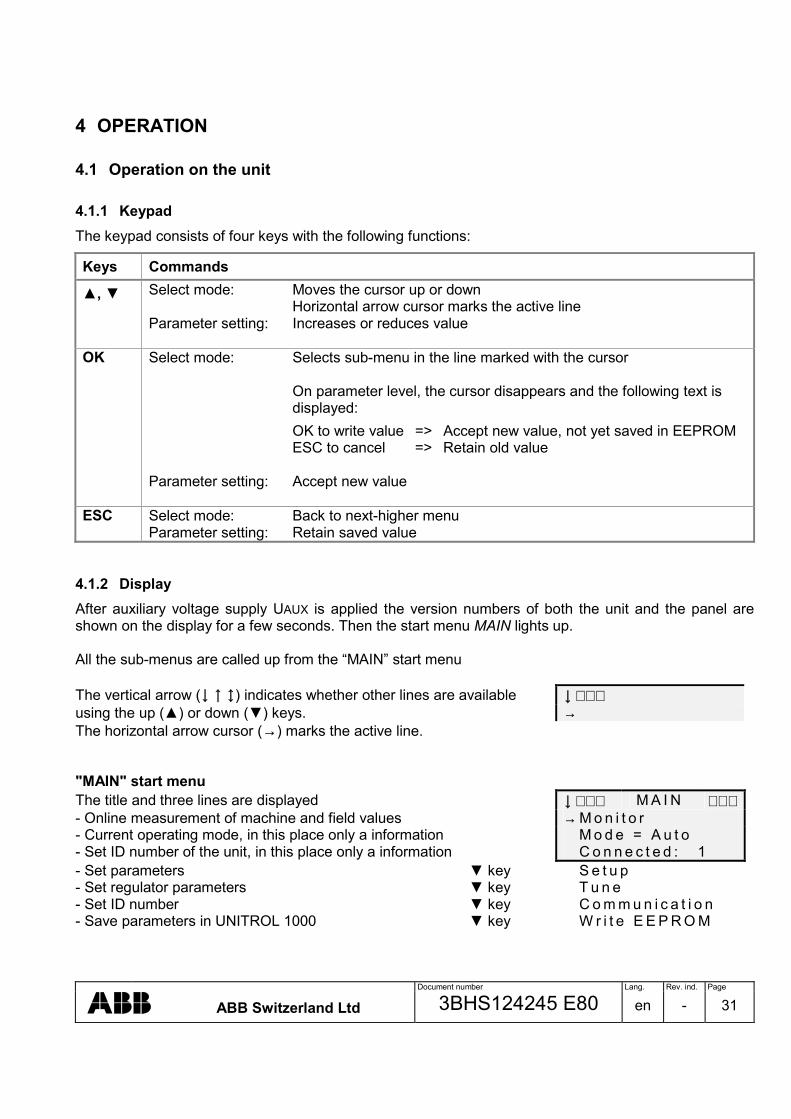
Document number Lang. Rev. ind. Page
ABB Switzerland Ltd 3BHS124245 E80 en - 31
4 OPERATION
4.1 Operation on the unit
4.1.1 Keypad The keypad consists of four keys with the following functions:
Keys Commands
, Select mode: Moves the cursor up or down Horizontal arrow cursor marks the active line Parameter setting: Increases or reduces value
OK Select mode: Selects sub-menu in the line marked with the cursor On parameter level, the cursor disappears and the following text is displayed:
OK to write value => Accept new value, not yet saved in EEPROM ESC to cancel => Retain old value Parameter setting: Accept new value
ESC Select mode: Back to next-higher menu Parameter setting: Retain saved value
4.1.2 Display After auxiliary voltage supply UAUX is applied the version numbers of both the unit and the panel are shown on the display for a few seconds. Then the start menu MAIN lights up. All the sub-menus are called up from the “MAIN” start menu The vertical arrow (↓ ↑ ) indicates whether other lines are available ↓ ∗ ∗ ∗ using the up () or down () keys. → The horizontal arrow cursor (→) marks the active line. "MAIN" start menu The title and three lines are displayed ↓ ∗ ∗ ∗ M A I N ∗ ∗ ∗ - Online measurement of machine and field values → M o n i t o r - Current operating mode, in this place only a information M o d e = A u t o - Set ID number of the unit, in this place only a information C o n n e c t e d : 1 - Set parameters key S e t u p - Set regulator parameters key T u n e - Set ID number key C o m m u n i c a t i o n - Save parameters in UNITROL 1000 key W r i t e E E P R O M

Document number Lang. Rev. ind. Page
ABB Switzerland Ltd 3BHS124245 E80 en - 32
4.1.3 Example of parameter setting Example: Assigning Parallel wGrid to input DI6
Operating Key Resulting display ↓ ∗ ∗ ∗ M A I N ∗ ∗ ∗ → M o n i t o r M o d e = A u t o
Display after auxiliary voltage is applied
C o n n e c t e d : 1
∗ ∗ ∗ M A I N ∗ ∗ ∗ M o d e = A u t o C o n n e c t e d : 1
In the start menu, use key to move down to setup 3x → S e t u p
∗ ∗ ∗ S E T U P ∗ ∗ S e t p o i n t s V o l t . D r o o p C o m p .
Select sub-menu 1, setup, and use key to move down to digital I/Os OK, 7x
→ D i g i t a l I / O s
D I G I T A L I / O s H y s t e r e s i s → I / O s
Select sub-menu 2, digital I/Os, and use key to move down to I/Os OK, 1x
D i n f r o m A i n
D I G I T A L I / O s D I O 4 D I 5
Select sub-menu 3, digital I/Os, and use key to move down to DI6 OK, 5x
→ D I 6
∗ ∗ ∗ D I 6 ∗ ∗ ∗ → D i n = N o n e P o l a r i t y = N o r m a l
Select sub-menu 4, DI6 OK
∗ ∗ ∗ D I 6 ∗ ∗ ∗ D i n = N o n e - O K t o w r i t e v a l u e
Select parameter DI Cursor disappears, text OK/ESC appears instead OK
- E S C t o c a n c e l
∗ ∗ ∗ D I 6 ∗ ∗ ∗ D i n = P a r a l l e l w G r i d - O K t o w r i t e v a l u e
Use key to select assignment 3x - E S C t o c a n c e l
∗ ∗ ∗ D I 6 ∗ ∗ ∗ → D i n = P a r a l l e l w G r i d P o l a r i t y = N o r m a l
Press OK key to save OK
∗ ∗ ∗ M A I N ∗ ∗ ∗ M o d e = A u t o C o n n e c t e d : 1
Press ESC key to return to start menu 4x ESC → S e t u p
Caution The above procedure only changes the parameters in the volatile memory.
To make the modification permanent, you have to save the entire parameter set: Save parameters: Start menu MAIN, Write EEPROM, OK, OK.

Document number Lang. Rev. ind. Page
ABB Switzerland Ltd 3BHS124245 E80 en - 33
4.1.4 Menu structure of display S t a r t m e n u S u b - m e n u 1 S u b - m e n u 2 S u b - m e n u 3 ∗ ∗ ∗ M A I N ∗ ∗ ∗ M o n i t o r ∗ ∗ ∗ M O N I T O R ∗ ∗ ∗ M o d e = A u t o U M = k V C o n n e c t e d : 1 U M r e l = % S e t u p I M 2 = A T u n e I M 2 r e l = % C o m m u n i c a t i o n Q = k V a r W r i t e E E P R O M Q r e l = % P = k W P r e l = % I e = A f r e q = H z
M A I N ∗ ∗ ∗ S E T U P ∗ ∗ ∗ S y s t e m D a t a ∗ S Y S T E M D A T A ∗ F i e l d F l a s h i n g U M N o m = k V S o f t S t a r t P T = P T : T h r e e p h a s e L i m i t e r s U M P r i m = k V S i n g l e p h a s e S y n c h r o n i z a t i o n U M S e c o n d = V 3 p h a s e g n d S e t p o i n t s I M 2 N o m = A V o l t . D r o o p C o m p . I M 2 P r i m = A D i g i t a l I / O s I M 2 S e c = A A n a l o g I n p u t s I e N o L o a d = A A n a l o g O u t p u t s K c e i l = V / V X q = M A I N , S E T U P ∗ F I E L D F L A S H I N G O f f L e v e l = % M A I N , S E T U P ∗ ∗ S O F T S T A R T ∗ ∗ S t a r t L v l = % H o l d T i m e = s R a m p T i m e = s M A I N , S E T U P ∗ ∗ ∗ L I M I T E R S ∗ ∗ ∗ V / H z L i m i t e r ∗ ∗ V / H z L I M I T E R ∗ ∗ I e M i n L i m i t e r f k n e e = H z I e M a x L i m i t e r S l o p e = % P Q L i m i t e r U M L i m i t e r B o o s t

Document number Lang. Rev. ind. Page
ABB Switzerland Ltd 3BHS124245 E80 en - 34
S u b - m e n u 2 S u b - m e n u 3 M A I N , S E T U P , L I M I T E R S ∗ I e M i n L I M I T E R ∗ M i n i m u m = A A c t i v e = M A I N , S E T U P , L I M I T E R S ∗ I e M a x L I M I T E R ∗ M a x i m u m = A H o l d T i m e = s - - - - - - - - - - - - - - - - - - - - - - D e l a y e d = A H o l d T i m e = s - - - - - - - - - - - - - - - - - - - - - - C o n t i n u o u s = A A c t i v e = M A I N , S E T U P , L I M I T E R S ∗ ∗ P Q L I M I T E R ∗ ∗ Q ( 0 % ) = % Q ( 2 5 % ) = % Q ( 5 0 % ) = % Q ( 7 5 % ) = % Q ( 1 0 0 % ) = % V o l t . D e p e n d = A c t i v e = M A I N , S E T U P , L I M I T E R S ∗ ∗ U M L I M I T E R ∗ ∗ M i n i m u m = % M a x i m u m = % M i n A c t i v e = M a x A c t i v e = M A I N , S E T U P , L I M I T E R S ∗ ∗ ∗ B O O S T ∗ ∗ ∗ T h r e s h o l d = %
H o l d T i m e = s H y s t e r e s i s = %
M A I N , S E T U P S Y N C H R O N I Z A T I O N M i n S l i p = H z M a x S l i p = H z M a x d U = % M a x A n g l = d e g T o t C B C t i m e = m s

Document number Lang. Rev. ind. Page
ABB Switzerland Ltd 3BHS124245 E80 en - 35
S u b - m e n u 2 S u b - m e n u 3 M A I N , S E T U P ∗ ∗ S E T P O I N T S ∗ ∗ A u t o ∗ ∗ A U T O P F ∗ ∗ P F S P V a r ∗ ∗ V a r S P M a n u a l ∗ ∗ M A N U A L S P O p e n L o o p ∗ O P E N L O O P S P ∗ M i n i m u m = % M a x i m u m = % R a m p R a t e = % / s ∗ ∗ ∗ U M A U X ∗ ∗ ∗ M i n i m u m = % M a x i m u m = % M A I N , S E T U P ∗ ∗ ∗ V D C ∗ ∗ ∗ P r i m . N e t I D = S e c . N e t I D = R a m p T i m e = s M A I N , S E T U P ∗ ∗ D I G I T A L I / O s ∗ ∗ H y s t e r e s i s ∗ ∗ H Y S T E R E S I S ∗ ∗ I / O s L o w L e v e l = V D i n f r o m A i n H i g h L e v e l = V

Document number Lang. Rev. ind. Page
ABB Switzerland Ltd 3BHS124245 E80 en - 36
S u b - m e n u 2 S u b - m e n u 3 S u b - m e n u 4 ∗ ∗ D I G I T A L I / O s ∗ ∗ D I O 1 D i r e c t i o n : I n p u t D i n D I O 2 ∗ ∗ ∗ D I O 1 D I O 3 N o n e , ∗ ∗ ∗ D I O 2 D I O 4 E x c i t a t i o n O N , ∗ ∗ ∗ D I O 3 D I 5 G e n C B c l . s t . , ∗ ∗ ∗ D I O 4 ∗ ∗ ∗ D I 6 P a r a l l e l w G r i d , D i r e c t i o n = D I 7 I n c r e a s e , D i n = D I 8 D e c r e a s e , D o u t = R e s e t S e t p o i n t , P o l a r i t y = R e m o t e S P E n a . , P F E n a b l e , V a r E n a b l e , M a n u a l E n a b l e , ∗ ∗ ∗ D I 5 O p e n L o o p E n a . , ∗ ∗ ∗ D I 6 S y n c , ∗ ∗ ∗ D I 7 V D C E n a b l e , ∗ ∗ ∗ D I 8 ∗ ∗ ∗ S e c o n d a r y N e t D i n = P o l a r i t y = D i r e c t i o n : O u t p u t D o u t N o n e , B o o s t , F i e l d F l a s h i n g , S y s t e m O K ∗ ∗ D I N f r o m A I N ∗ L i m i t A c t i v e , S u b - m e n u 4 D I 9 f r o m + A I V / H z L i m . A c t . , D I 1 0 f r o m - A I S P L i m . R e a c h . , ∗ ∗ D I 0 9 D I 1 1 f r o m + A I S P M i n . R e a c h . , ∗ ∗ D I 1 0 D I 1 2 f r o m - A I S P M a x . R e a c h . , ∗ ∗ D I 1 1 D I 1 3 f r o m + A I O p e r . L i m . A c t . , ∗ ∗ D I 1 2 D I 1 4 f r o m - A I M i n I e A c t . , ∗ ∗ D I 1 3 M a x I e A c t . , ∗ ∗ D I 1 4 f r o m – A I ∗ M i n P Q A c t . , D i n = M i n U M A c t . , P o l a r i t y = M a x U M A c t . , V o l t a g e R e l a y , C l o s e C B C o m d , S y n c C h e c k , S W A l a r m P o l a r i t y : N o r m a l , I n v e r t e d

Document number Lang. Rev. ind. Page
ABB Switzerland Ltd 3BHS124245 E80 en - 37
S u b - m e n u 1 S u b - m e n u 2 S u b - m e n u 3 A i n : N o n e , A u t o R e m o t e S P , P F R e m o t e S P , V a r R e m o t e S P , M a n u a l R e m S P , O p e n L o o p R S P , U M a u x , R e s e r v e d 2 , R e s e r v e d 3 , R e s e r v e d 4 , R e s e r v e d 5 , D I 9 ( + ) & 1 0 ( - ) , D I 1 1 ( + ) & 1 2 ( - ) , D I 1 3 ( + ) & 1 4 ( - ) M A I N , S E T U P ∗ A N A L O G I N P U T S A I 1 ∗ ∗ ∗ A I 1 A I 2 ∗ ∗ ∗ A I 2 A I 3 ∗ ∗ ∗ A I 3 ∗ ∗ ∗ A i n = U i n 0 % = V U i n 1 0 0 % = V A o u t : N o n e , E x c . C u r r e n t , P W M F b i a s A I N , S E T U P A N A L O G O U T P U T S A O 1 ∗ ∗ ∗ A O 1 A O 2 ∗ ∗ ∗ A O 2 ∗ ∗ ∗ I e R a n g e A o u t = F b i a s R a n g e U o u t 0 % = V U o u t 1 0 0 % = V M A I N , S E T U P , A N A L O G O U T P U T S ∗ ∗ I e R A N G E ∗ F b i a s R A N G E ∗ F b i a s 0 % = %
F b i a s 1 0 0 % = %
M A I N ∗ ∗ ∗ T U N E ∗ ∗ ∗ A u t o ∗ ∗ ∗ A U T O ∗ ∗ ∗ P F / V a r / P Q L i m i t e r S e t p o i n t = % M a n u a l / I e L i m i t e r V p = O p e n L o o p T a = s T b = s K q = % S t e p = % D o S t e p

Document number Lang. Rev. ind. Page
ABB Switzerland Ltd 3BHS124245 E80 en - 38
S u b - m e n u 1 S u b - m e n u 2 M A I N , T U N E P F / V a r / P Q L I M I T E R S P P F = S P V a r = % V p = T a = s P F - S t e p = V a r - S t e p = D o P F - S t e p D o V a r - S t e p M A I N , T U N E M A N U A L / I e L I M I T E R S e t p o i n t = A V p = T a = s S t e p = A D o S t e p M A I N , T U N E ∗ ∗ O P E N L O O P ∗ ∗ S e t p o i n t = % S t e p = % D o S t e p =
M A I N ∗ C O M M U N I C A T I O N A V R I D =
M A I N ∗ ∗ ∗ M A I N ∗ ∗ ∗ W r i t e E E P R O M - O K t o w r i t e v a l u e - E S C t o c a n c e l
4.1.5 Fault message on the display In certain circumstances it could appear the following fault messages on the display: − XIRQ, SI or SYSTEM HALTED The regulator continues to work faultless and has not to be taken out of service. But, no parameters can be entered or changed. The display is reseted when the unit is taken out of service and the auxiliary power is disconnected for a short-time. A defective unit should be sent in for repair. See manufacturer’s details in section 1.3.

Document number Lang. Rev. ind. Page
ABB Switzerland Ltd 3BHS124245 E80 en - 39
4.2 PC-Software The delivered PC software is called PCTools for UNITROL 1000. System requirements: - at least Pentium II (200MHz) processor - 256 MB RAM - 4-speed CD-ROM drive - Microsoft® WindowsTM 95/98, NT or 2000
Installing PCTools 3.0 software To install the PCTools software please carry out the following steps: • Place the PCTools CD in your CD-ROM drive • Open the Windows File Manager or Explorer • Display the CD root directory • Double-click Visa201.exe from the directory PCTools \ Installer \ Disks • Double-click Setup.exe from the directory PCTools \ Installer \ Disks • Follow the instructions that appear on the screen. The Setup loads the
PCTools program into your hard disk. The application program is now installed. To start the program: • Open the user interface via Start button, Programs, UNITROL 1000 and
Double-click the shortcut icon PCTools.
Distribution rights: PCTools was developed with the LabVIEW software and is distributed free of license charges and costs. The copyright to LabVIEW is owned by the company National Instruments International Distribution (NIID). “Copyright © [02-03-10] National Instruments Corporation.“

Document number Lang. Rev. ind. Page
ABB Switzerland Ltd 3BHS124245 E80 en - 40
4.2.1 Operation using the software The window PCTools is the graphic user interface of the program. The other sub-menus are called up from the menu bar: - File: Load/save parameters - Monitor: Online measuring - Setup: Set parameters - Com.: Set ID number - Tune: Tune regulator - Help: Software information
PCTools
File Monitor CommunicationSetup Tune
+
Connected to:
Help
EEPROM
OFF LINE
AVR1
menu bar, start menu
ABB PCTools for UNITROL 1000
ID-Number
Display on the unit: After the connection cable has been connected, the unit display reads REMOTE CONTROL. → R E M O T E C O N T R O L Note It is possible to connect or disconnect the cable while the unit is in operation. To make the communication between PCTools and the unit: • Click the button OFF LINE
Caution: This button is shaded, if PCTools can not communicate with the unit. • Press the button „Continue“ to
accept the reading of the parameters.
PCTools
File Monitor CommunicationSetup Tune
+
Connected to:
Help
EEPROMAVR1Reading Parameters from AVR
100.0% Ready
CancelParameters Read OK
Continue
+
OFF LINEclick
Button lights up green
LED lights up green
ON LINE
2nd click
The button is now with ON LINE labelled and lights up green The parameters have been loaded from the unit to PCTools (EEPROM LED lights up green)

Document number Lang. Rev. ind. Page
ABB Switzerland Ltd 3BHS124245 E80 en - 41
4.2.2 Example of parameter setting using PCTools Example: Assigning Parallel with Grid Status to input DI6 Make ON-LINE connection to the unit
Menu bar PCTools, start menu - Select setup - Select digital I/Os - Open input DI6 withmenu - Select input Return to start menu
PCToolsFile Monitor CommunicationSetup Tune
+
+ Digital I/Os
click
System DataSoft Start
LimitersSetpoints
Analog Output
Help
Field Flashing
Voltage Droop Composition
Analog Input
click
In NormalNoneDIO1
NormalNoneDI5
Direction Digital Input/Output Polarity
NormalNoneDI6
NormalParallel with Grid StatusDI6
NoneExcitation ONGen CB Closed Status
IncreaseDecreaseReset SetpointRemote SP EnablePF EnableVar EnableManual EnableOpen Loop Enable
click
click
VDC EnableSecondary Net
Synchronize
Close
Synchronization
Reset AlarmStandby
Parallel with Grid Status
Digital I/Os
Caution The above procedure only changes the parameters in the volatile memory.
To make the modification permanent, you have to save the entire parameter set. Save parameters in ON LINE status: - Unit: Menu bar PCTools \ File \ Write Parameters to EEPROM - Harddisk: Menu bar PCTools \ File \ Save Parameter File

Document number Lang. Rev. ind. Page
ABB Switzerland Ltd 3BHS124245 E80 en - 42
4.2.3 Menu structure of PCTools
+ PCTools File Monitor Setup Communication Tune Help
About PCTools… Software information About PCTools Control: Software revision unit Panel: Software revision panel Revision: Software revision PCTools Click window to continue Connected AVR
+
Software RevisionsControl: X.XXXPanel: X.XXX Click window to continue
ABB for UNITROL 1000Revision: X.XXX
PCTools
File Monitor Setup Communication Tune Help
Open Parameter File *.ini Save Parameter File Write Parameters to EEPROM Close close the application
File Monitor Setup Communication Tune Help
Measurements Online measurement of the machine and field values Oscilloscope Online measurement PQ Diagram Online measurement Sync Diagram Online measurement
• Window measuring instruments
Monitor \ Measurements
- Network Voltage (UNET) [% and kV] - Machine Voltage (UM) [% and kV] - Machine Real Power (P) [% and kW] - Field Current (Ie) [A] - Machine Current (IM2) [% and A] - Machine Reactive Power (Q) [% and kVar - Network Frequency (fNET) [Hz] - Machine Frequency (fM) [Hz] - Power Factor (PF) --
5025
75
0
100125
150
%
Measurements+
Close
0.00.000
Machine Voltage (UM)
kV

Document number Lang. Rev. ind. Page
ABB Switzerland Ltd 3BHS124245 E80 en - 43
• Oscilloscope
Monitor \ Oscilloscope File Edit Start
Open Waveform Ctrl+O open the waveform (is saved as ASCII table, *.xls) Recall Setup open settings of oscilloscope (*. cfg)
Save Waveform save measurements as ASCII table (*.xls) Save Setup save oscilloscope settings (*. cfg)
Print Bitmap to File Ctrl+B save waveform in a BMP File
Close Ctrl+Q close application
File Edit Start
Cursors Ctrl+C show / hide cursors, Cursor appear on the left side of the screen Sweep Buffer Ctrl+S Run through recording from Cursor A
File Edit Start
Start start the record (appears menu point Freeze Waveform) Freeze Waveform stop the record (appears menu point Start)
File Edit Start
0.0 5.0 10.0 15.0 20.0 25.0 30.0 35.0 40.0 45.0 50.0
time / s
Channel 1
Channel 2
Channel 3
Channel 4
Generator StateModeCombined Limit-------------PWMIeUM Relative
f MachineP RelativeQ RelativecosphiIq Relative
Limit Ie MaxLimit PQ Min
PWM
%/div
%0.0
100.0
Ie
A/div
A0.0
10.0
f Machine
Hz/div
Hz0.0
50.0
UM Relative
%/div
%0.0
50.0
IM2 Relative
sBuffer Length
Channel 1 Channel 1A B
click0.0 %0.0 s
Channel 1Channel 2Channel 3Channel 4
dt = 0.0 s1/dt = Inf Hz
Cursors A, B
Zoom
50.0
UM StepPF StepVar StepIe Step
click
Iq Relative Slow
GainOffset
Cursors A, B
Sampling rate = 20 Samples / Second
Measurement: Define buffer length (max. length = 100 s) Start, stop and save record The assignment of the signal, gain, offset can be chosen afterwards.
Note: A reduced buffer length improves considerably the performance of the PC.

Document number Lang. Rev. ind. Page
ABB Switzerland Ltd 3BHS124245 E80 en - 44
• Window PQ Diagram
Monitor \ PQ Diagram (Power chart)
125
100
75
50
25
0-300 -275 -250 -225 -200 -175 -150 -125 -100 -75 -50 -25 0 25 50 75 100
x
x
x
x
x
Operating points
Limiter characteristics100
75
50
25
0
Close
• Window Synchonization Diagram
Monitor \ Sync Diagram
Close
-0.8 -0.6 -0.4 -0.2 0.0 0.2 0.4-10.0
-6.0
-4.0-2.0
0.0
2.04.06.0
8.0
10.0
-8.0
-20
-20-40
-60
-80
-100
-120
-140-160180
160140
120
100
80
60
4020
0
Angle Frequency/Voltage
x
UM - UNET [%]
fM -fNET
[Hz]
Slip
Differential voltage machine to network
Synchronization
Synchronoscope
Close command
0,05 Hz

Document number Lang. Rev. ind. Page
ABB Switzerland Ltd 3BHS124245 E80 en - 45
File Monitor Setup Communication Tune Help
Setting of the system and unit parameters System Data System Data Soft Start Soft Start Field Flashing Field Flashing Limiters Limiters Setpoints Setpoints Voltage Droop Compensation Voltage Droop Compensation Control Digital I/Os Digital I/Os Analog Inputs Analog Inputs Analog Outputs Analog Outputs Synchronization Synchronization Limiters V/Hz Limiter Operational Limits PQ, Ie und UM limiter Boost Line short circuit support Setpoints Auto Min., max. and ramp PF Var Manual Open Loop UMaux

Document number Lang. Rev. ind. Page
ABB Switzerland Ltd 3BHS124245 E80 en - 46
• Adjust System Data
Setup \ System Data
IM2 NominalA
S NominalUM NominalkV
Ie No LoadA
Xq
Kceiling
UM Nominal @ AVRV
IM2 Nominal @ AVRA
Primary Secondary:
Potential Transformer
kV V
Primary Secondary:
Current Transformer
A A
V/V
PT
Three PhaseSingle PhaseThree ph gnd
110.00 1.000
5.0
5.00
1.50
1.000 110.00 500 1.000
5001.000 MVA0.87
Three Phasecli
ck
Close
• Configure Soft Start
Setup \ Soft Start
0.0 2.0 4.0 6.0 8.0 10.0 12.0 14.0 16.0 18.0 20.0
100
80
60
40
20
00.0 2.0 4.0 6.0 8.0 10.0 12.0 14.0 16.0 18.0 20.0
sRamp Time
sHold Time
%
110
0.0
0.0
10.0
Close
Start Level
• Adjust Field Flashing
Setup \ Field Flashing
%Field Flashing Off Level 0.0
Close
0.0
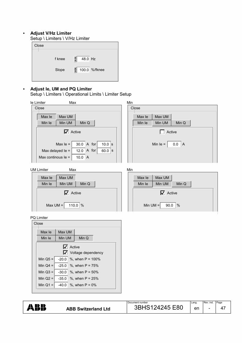
Document number Lang. Rev. ind. Page
ABB Switzerland Ltd 3BHS124245 E80 en - 47
• Adjust V/Hz Limiter
Setup \ Limiters \ V/Hz Limiter
f knee Hz
Slope %/fknee100.0
48.0
Close
• Adjust Ie, UM and PQ Limiter
Setup \ Limiters \ Operational Limits \ Limiter Setup Ie Limiter Max Min
Active
Max Ie = Min Q30.0
Max delayed Ie = Min Q12.0
Max continous Ie = Min Q10.0
Min Q10.0
Min Q60.0
Min QMin UMMax UM
Min Ie
ss
forfor
A
AA
Active
Min Ie = Min Q0.0
Min QMin UMMax UMMax Ie
A
Max IeMin Ie
Close Close
UM Limiter Max Min
Active
Min QMin UMMin Ie
Active
Min QMin IeMax UMMax Ie
Min UM = Min Q90.0 %Max UM = Min Q110.0 %
Min UMMax UMMax Ie
PQ Limiter
Active
Min UMMax UM
Min IeMax Ie
Voltage dependency
Min Q5 = Min Q-20.0 %, when P = 100%
Min Q4 = Min Q-25.0 %, when P = 75%
Min Q3 = Min Q-30.0 %, when P = 50%
Min Q2 = Min Q-35.0 %, when P = 25%
Min Q1 = Min Q-40.0 %, when P = 0%
Min Q
Close

Document number Lang. Rev. ind. Page
ABB Switzerland Ltd 3BHS124245 E80 en - 48
• Adjust short circuit support
Setup \ Limiters \ Boost
Threshold %
Hold Time
Hysteresis %
s
40.0
3.0
15.0
Close
• Adjust Setpoint Range
Setup \ Setpoints \ AUTO
Minimum %
Maximum
Ramp Rate %/s
%
90.0
110.0
0.30
Close
The setpoints PF, Var, Manual, Open loop and UMaux are entered in identical input fields. • Adjust Voltage Droop Compensation Control Range
Setup \ Voltage Droop Compensation
Primary Net ID
Secondary Net ID
VDC Ramp Time s
1
2
10.0
Close

Document number Lang. Rev. ind. Page
ABB Switzerland Ltd 3BHS124245 E80 en - 49
• Configure Digital I/O
Setup \ Digital I/Os
In NormalNoneDIO1
High Level V
Low Level V
Direction Digital Input/Output Polarity
click
10.0
4.0
In NormalNoneDIO2Inverted
None NormalInDIO3
NoneDIO4 NormalIn
NormalNoneDI5
NormalNoneDI6
NormalNoneDI7
NormalNoneDI8
NormalNoneDI9 from +AI
NormalNoneDI10 from -AI
NormalNoneDI11 from +AI
NormalNoneDI12 from -AI
NormalNoneDI13 from +AI
NormalNoneDI14 from -AI
NoneExcitation ON
Parallel with Grid StatusGen CB Closed Status
IncreaseDecreaseReset SetpointRemote SP EnablePF EnableVar EnableManual EnableOpen Loop Enable
Direction = OutNoneBoost
Direction = In
VDC EnableSecondary Net
FieldFlashing
Limit ActiveV/Hz Limit ActiveSP Limit ReachedSP Minimum ReachedSP Maximum ReachedOperational Limit ActiveMin Ie ActiveMax Ie ActiveMin PQ ActiveMin UM ActiveMax UM ActiveVoltage Relay
click
Out
Synchronize
SystemOK
Close
click
Reset AlarmStandby CloseCBCommand
Sync CheckSW Alarm

Document number Lang. Rev. ind. Page
ABB Switzerland Ltd 3BHS124245 E80 en - 50
• Configure Analog Inputs Setup \ Analog Inputs
Analog Input 0% 100%
NoneAI2 V V
NoneAI3 V V
NoneAI1 V V0.0
0.0
0.0 10.0
10.0
10.0
Close
NoneAuto Remote Setpoint
Var Remote SetpointPF Remote Setpoint
Manual Remote SetpointOpen Loop Remote SetpointUMauxReserved2Reserved3Reserved4Reserved5Digital Input 9(+) & 10(-)Digital Input 11(+) & 12(-)Digital Input 13(+) & 14(-)
click
• Configure Analog Outputs
Setup \ Analog Outputs
NoneAO1 V V
NoneAO2 V V
% %
A A
maxmin
Ie Range
PWM
0.0
0.0
0.0
10.0
10.0
30.0
0.0 100.0
Analog Output
Close
Excitation CurrentNone
PWMFbias
click
Hz HzFbias Range -3.0 3.0

Document number Lang. Rev. ind. Page
ABB Switzerland Ltd 3BHS124245 E80 en - 51
• Adjust Synchronization
Setup \ Synchronization
Minimum Slip
Maximum Slip
Maximum Delta U
Hz0.00
-0.40
Close
Maximum Delta Angle
Total CB Closing Time
10
90
5.00
Hz
%
deg
ms
File Monitor Setup Communication Tune Help
ID Definition Set ID number • Set ID Number
Communication \ ID Definition Note: Required in VDC mode to be set unique
ID 1
Close

Document number Lang. Rev. ind. Page
ABB Switzerland Ltd 3BHS124245 E80 en - 52
File Monitor Setup Communication Tune Help
Setpoint Adjust Auto Automatic voltage regulation PF/Var/PQ Limiter PF, Var regulation and PQ Limiter Manual/Ie Limiter Manual control and Ie Limiter
• Adjust Setpoint, Trigger Setpoint, Status Displays
Tune \ Setpoint Adjust
Setpoint
UP
%
DOWN
%
UPDOWN
UM Step
110.0
105.0
100.0
95.0
90.0
Limiter State
Ie High
UM High
IM High
V/Hz
Ie Low
UM Low
Iq Low
Active ModeGenerator State
Close
Sec. Net
Grid
Prim. Net
0.0
100.0
Open Loop
Pf
Var
VDC
Sync
Manual
Standby
NoLoad
AUTO
A setpoint jump can also be triggered in this window.
Adjust setpoint
Set step height
Trigger setpoint jump
• Parameter Setting Range
Tune \ Auto
Vp(Proportional Gain)
Ta(Integration Time)
s
Kq(Droop)
Tb(Derivation Time)
s%
5.00
2.00
1.00
3.00
4.00
0.01
20.00
15.005.00
0.01
10.00
175
150
125100
75
50
25
0 200
15
20
10
50
-5
-10
-15
-20
20.0 1.00
0.0 0.35
Close
- Tune \ PF/Var/PQ Limiter - Tune \ Manual/Ie Limiter
Vp(Proportional Gain)
Ta(Integration Time)
s
20.00
15.005.00
0.01
10.00
175
150
125100
75
50
25
0 200
20.0 1.00
Close

Document number Lang. Rev. ind. Page
ABB Switzerland Ltd 3BHS124245 E80 en - 53
4.2.4 Save parameter file PC UN 1000
Write Parametersto EEPROM
PCTools
ON LINE
OFF LINESave Parameter FileOpen Parameter File
Parameters
RAM
Parameters
EEPROM
LED lights up, if data RAM = EEPROM (ON LINE)EEPROM
Harddisk
• Status ON-LINE
After switching from OFF LINE to ON LINE, PCTools reads the parameters from the device‘s RAM. Now, all parameter changes carried out using PCTools are written directly into the device‘s RAM. - Write Parameters to EEPROM: The parameters in the RAM are stored in the device. - Save Parameter File: The parameters are saved onto the hard disk as an INI file. - Open Parameter File: The INI file is loaded into PCTools and the RAM is overwritten
again. Caution: The old parameter file is immediately overwritten in the RAM!
• Status OFF-LINE Any parameter changes carried out in PCTools are not transferred into the device. - Write Parameters to EEPROM: No effect, since there is no communication between PCTools and
the device. - Save Parameter File: The parameters are saved onto the hard disk as an INI file. - Open Parameter File: The INI file is only loaded into PCTools.
Caution: If you now switch to ON-LINE, PCTools loads the old data from the RAM again!
• Editing the Parameter file:
The INI file can be opened using an editor (Word, Note- or Wordpad) or by double-clicking on the filename and the parameters can be edited directly and printed out.
Caution When entering the parameters, it should be ensured that the permissible ranges of
values are not exceeded and that the specified syntax is observed.
If the parameters in *.ini file are not correct, serious damage can be caused on the plant!

Document number Lang. Rev. ind. Page
ABB Switzerland Ltd 3BHS124245 E80 en - 54
4.2.5 Evaluation of the waveform The curves for the current and stored data can be viewed using the oscilloscope, PQ diagram and the instruments. (Monitor toolbar)
File Edit Start
0.0 5.0 10.0 15.0 20.0 25.0 30.0 35.0 40.0 45.0 50.0
time / s
Channel 1
Channel 2
Channel 3
Channel 4Gen. State
/div0.0
2.0
Combined Limit
/div0.01.0
Iq Relative
%/divHz0.0
100.0
UM Relative
%/div
%0.050.0
sBuffer Length
Channel 3 Channel 3A B
0.0 %24.0 s
dt = 10.3 s1/dt = 0.097Hz
50.0
0.0 %34.3 s
1
2
3
4
1
2
4
3A B
Sweep Buffer
Cursors A, B
Freeze Waveform
125
100
75
50
25
0-300 -275 -250 -225 -200 -175 -150 -125 -100 -75 -50 -25 0 25 50 75 100
x
x
x
x
x
PQ Limiter is active
limiter characteristics100
75
50
25
0
Close
5025
75
0
100125
150
[%]
Measurements+
Close
106.7
1.067
Machine Voltage [UM]
[kV]
Zoom
• Status OFF LINE
File \ Open Waveform: Open stored waveform file. Edit \ Cursors: Assign channel with buttons A and B, use left mouse button to drag cursor A to the desired point on the signal curve. The measured values can be measured on the oscilloscope, instruments or PQ diagram.
Edit \ Sweep Buffer: The curves are run through from cursor point A using the scanning bar. • Status ON LINE
Start: The recording of the waveform is started. Freeze Waveform: The recording is stopped. File \ Save Waveform: Save waveform. File \ Save Setup: Save oscilloscope settings.
− The window in "Tune“ can also be opened to set the regulators. − The setpoint step is simulated in "Tune Setpoint Adjust“. − The buffer length can be adjusted from 1 s, 2 s, 5 s, 20 s, 50 s to 100 s. − The time scale can be adjusted in the bar above the waveform (Zoom).

Document number Lang. Rev. ind. Page
ABB Switzerland Ltd 3BHS124245 E80 en - 55
Monitor \ oscilloscope, status display There are 3 quasi analogue signals which can be used to represent status changes on the oscilloscope. Decoding of the signals Generator State, Mode and Combined Limit.
Generator StateModeCombined Limit-------------PWMIeUM Relative
f MachineP RelativeQ RelativecosphiIq Relative
SlipUNetRelative
IM2 Relative
UM StepPF StepVar StepIe Step
Angle
signal value state Generator State: 0 = Idle (NoLoad) 1 = Change NoLoad -> Net1 2 = Net 1 3 = Change Net1 <-> Net2 4 = Net 2 5 = Change Net2 -> NoLoad 6 = Net1 or Net2 -> Grid ON 7 = Grid ON => see channel 4, picture previous page 8 = Grid ON -> Net1 or Net2 Mode: 0 = Auto 1 = Var 2 = PF 3 = Manual 4 = Open Loop 5 = VDC 6 = Sync 7 = Standby Combined Limit: 0 = None 1 = Ie Min 2 = UM Min 3 = PQ Min => see channel 3, picture previous page 4 = Ie Max 5 = UM Max +8 = V/Hz *)
*) Each time a limiter is tripped, the V/Hz-Limiter can also occur and be displayed in the status signal of
the limiters. All other collective signals only allow one display . Summary of the limiter status:
NoneIe Min
PQ MinUM Min
Ie MaxUM Max
V/Hz
1.0
Combined Limit
+82.03.04.05.0
8.09.0
10.011.0
Ie Min +V/HzUM MinPQ MinIe MaxUM Max
+V/Hz
+V/Hz+V/Hz
+V/Hz12.013.0
1.0/div
+8
s

Document number Lang. Rev. ind. Page
ABB Switzerland Ltd 3BHS124245 E80 en - 56
4.2.6 Error message • Error message during the reading of the parameters The following message appears if the connection is interrupted during the reading of the parameters.
PCTools
File Monitor CommunicationSetup Tune
+
Help
ON LINE
Reading Parameters from AVR
100.0% Ready
Cancel
Error 0 occurred at Time Out.
Continue
+
Possible reasons:
FieldPoint: IAK operation was successful.orIA Servers: IAK operation was successful.orNI-488: Error connecting to driver or device.
− Acknowledge by clicking on the Continue button. − Check connection between PC and device and click OFF LINE button again. • Error message at assigning of the digital input with the signal Synchronize The Error message appears, when the relevant unit does not include the option Synchronization.
OK
+
Synchronization is not possible with this unit
Note You can ask for information directly from the manufacturer, in case the option
„Synchronization“ is required to this unit. See manufacturer’s details in section 1.3.
Document number Lang. Rev. ind. Page
ABB Switzerland Ltd 3BHS124245 E80 en - 57
5 COMMISSIONING
5.1 Safety regulations
UNITROL 1000 units operate with dangerous voltages of up to 250 V AC. Manipulation of live parts can lead to death or injury to the persons involved or damage to the surroundings. Possible risks are largely excluded if the unit is handled properly in accordance with these instructions.
All relevant regulations must be complied with during commissioning. It is essential that these safety regulations are read before starting any work on the UNITROL 1000 equipment.
After the unit has been switched off, it must be ensured by measurement that no measuring voltages or control voltages >50 V are present at the terminals. At an interrupted field circuit the input capacitor is slowly discharged through internal circuits. In order to prevent unintentional closing of open voltage circuits by third parties, the circuits in question should be identified at the point of interruption (e.g. by means of a warning sign).
If work is being carried out in the vicinity of the UNITROL 1000, all voltages greater than 50 V leading to the system must be switched off.
Caution Before switching on, always check whether the connection terminals are wired up
according to the plant schematic.

Document number Lang. Rev. ind. Page
ABB Switzerland Ltd 3BHS124245 E80 en - 58
5.2 Setting aids At the first commissioning all parameters have to be controlled. For this see description of the parameters in section 2.2.2 and settings recorded in section 7.3. Overview of parameter blocks • Setup: - System Data - Field Flashing - Soft Start - Limiters
- Synchronization - Setpoints
- Voltage Droop Compensation Control - Digital I/O
- Analog I/O • Tune: Controller • Communication: ID unit number. Setting aids • Setup \ System Data, Ceiling Factor Kceil
UeoUeKceil
max=
Uemax: maximum output voltage Ueo: output voltage at nominal voltage of the machine (machine in no-load operation)
Regulator
ESM
U PWR
U emax
U eo
Definition: The ceiling factor Kceil determines the relationship between the maximum output voltage of the regulator and the exciter voltage which is required for no-load excitation and is thus a measure for the possible overexcitation of the machine. The greater the ceiling factor, the faster the regulator can react drops in the machine voltage and/or reactive power. On the other hand the smaller the ceiling factor, the faster the regulator can react load off.
The ceiling factor is dependent on the available supply voltage UPWR. Power electronics supply: three- phase: Uemax = 1.40 * UPWR – 8 V single-phase: Uemax = 1.25 * UPWR – 8 V DC: Uemax = 0.98 * UPWR – 8 V Example: Specifications: Power electronics supply UPWR = 240 V, single-phase
No-load exciter voltage Ueo = 150 V
Calculation: Uemax = 1.25 * 240 V – 8 V = 292 V Kceil = 292 V/150 V = 1.95 p.u.

Document number Lang. Rev. ind. Page
ABB Switzerland Ltd 3BHS124245 E80 en - 59
• Setup \ System Data, Machine Reactance Xq - Salient pole machine: Xq ≈ 0.7 to 0.5 Xd - Cylindrical-rotor machine (Turbo): Xq ≈ Xd • Setup \ Limiter, Manual und Open Loop
There are no limiters active in the mode Manual and Open loop. • Setup \ Limiter, UM Limiter
The limiting values of the UM limiter are, as a rule, set equally, like the setpoint range of the voltage regulator (Auto mode).
Setpoint Auto UM Limiter Example Minimum = Minimum 90% Maximum = Maximum 110%
• Setup \ Synchronization
Caution The machine frequency has to be always greater than network frequency.
It can not be synchronized by a positive slip.

Document number Lang. Rev. ind. Page
ABB Switzerland Ltd 3BHS124245 E80 en - 60
• Setup \ Digital I/Os, configuration
Software configuration of the digital I/Os: − Check switching threshold of the inputs. Default values apply to internal 24 V supply. − Define terminal as input or output − Assign terminal to desired signal − Select polarity
• Setup \ Analog inputs / outputs, configuration
Software configuration of the analog inputs: − Assign terminal to desired signal − Define signal level of the input signal [Uin0% … Uin100%] − If the input is used as a digital input, the desired signal name is to be assigned in the menu
Digital I/Os.
Software configuration of the analog outputs: − Assign terminal to desired signal − Define signal level of the output signal [Uin0% to Uin100%] − Define signal level of the field current [Ie0% to Ie100%]
• Setup \ Digital I/Os, selection of operating mode
The operating mode is selected via the digital inputs. For this purpose, a maximum of 10 inputs have to be occupied by the following signals:
Mode Digital inputs which are to be assigned
Exc. ON
Stand by
SYN Gen CB Closed Status
Parallel with Grid Status
Manual Enable
Open Loop
Enable
VDC Enable
PF Enable
Var Enable
OFF 0 V X X X X X X X X X Standby 24 V 24 V X X X X X X X X Sync 24 V 0 V 24 V X X X X X X X Manual 24 V 0 V 0 V X X 24 V X X X X Open Loop 24 V 0 V 0 V X X 0 V 24 V X X X VDC 24 V 0 V 0 V 24 V 0 V 0 V 0 V 24 V X X PF 24 V 0 V 0 V 24 V 24 V 0 V 0 V 0 V 24 V X Var 24 V 0 V 0 V 24 V 24 V 0 V 0 V 0 V 0 V 24 V Auto 24 V 0 V 0 V 0 V X 0 V 0 V X X X
with *) 24 V 0 V 0 V 24 V X 0 V 0 V 0 V 0 V 0 V *) with droop or compensation X = not relevant 0 V = 0 V or open Note: If an input is to be continuously active (24 V), then it should only be inverted by software
means. The input then naturally counts as being occupied. The inputs DI9 to DI14 can be used as virtual digital inputs even if they are not defined in Analog Inputs as Digital Inputs.
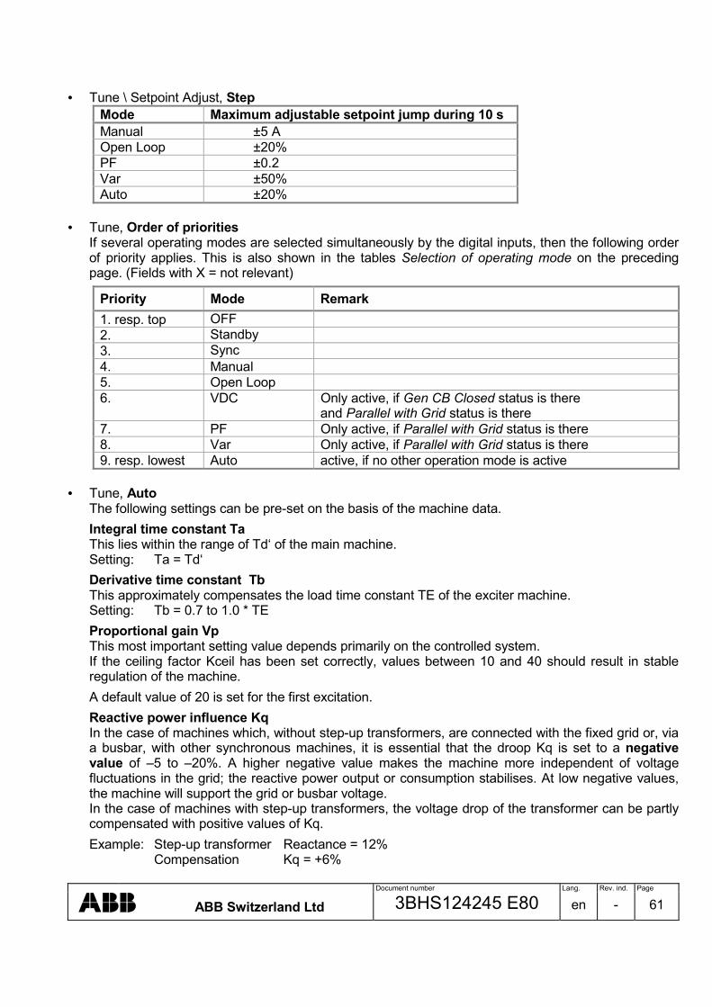
Document number Lang. Rev. ind. Page
ABB Switzerland Ltd 3BHS124245 E80 en - 61
• Tune \ Setpoint Adjust, Step
Mode Maximum adjustable setpoint jump during 10 s Manual ±5 A Open Loop ±20% PF ±0.2 Var ±50% Auto ±20%
• Tune, Order of priorities
If several operating modes are selected simultaneously by the digital inputs, then the following order of priority applies. This is also shown in the tables Selection of operating mode on the preceding page. (Fields with X = not relevant)
Priority Mode Remark 1. resp. top OFF 2. Standby 3. Sync 4. Manual 5. Open Loop 6. VDC Only active, if Gen CB Closed status is there
and Parallel with Grid status is there 7. PF Only active, if Parallel with Grid status is there 8. Var Only active, if Parallel with Grid status is there 9. resp. lowest Auto active, if no other operation mode is active
• Tune, Auto
The following settings can be pre-set on the basis of the machine data.
Integral time constant Ta This lies within the range of Td‘ of the main machine. Setting: Ta = Td‘
Derivative time constant Tb This approximately compensates the load time constant TE of the exciter machine. Setting: Tb = 0.7 to 1.0 * TE
Proportional gain Vp This most important setting value depends primarily on the controlled system. If the ceiling factor Kceil has been set correctly, values between 10 and 40 should result in stable regulation of the machine.
A default value of 20 is set for the first excitation.
Reactive power influence Kq In the case of machines which, without step-up transformers, are connected with the fixed grid or, via a busbar, with other synchronous machines, it is essential that the droop Kq is set to a negative value of –5 to –20%. A higher negative value makes the machine more independent of voltage fluctuations in the grid; the reactive power output or consumption stabilises. At low negative values, the machine will support the grid or busbar voltage. In the case of machines with step-up transformers, the voltage drop of the transformer can be partly compensated with positive values of Kq.
Example: Step-up transformer Reactance = 12% Compensation Kq = +6%

Document number Lang. Rev. ind. Page
ABB Switzerland Ltd 3BHS124245 E80 en - 62
5.3 Work carried out while machine is at a standstill Preliminary checks: • Wiring check, compare connections with schematic
Caution Unit connection terminal 7 has to be earthed.
Caution Disconnect cables before the meggers (with the insulation tester) on the unit. The unit could be damaged.
• Switch on auxiliary voltage UAUX
• Adjust parameters
• Check measuring voltage and current transformer circuits
• Measure field resistance
• Low-load test: external supply of power electronics (3x <250 V AC) - Open loop mode, polarity
- Optimise Ie regulator • Adjust limiter settings on the basis of customer’s power chart Reminder, generator: short circuit and no-load tests.
5.4 Work carried out while machine is running No-load tests: (nominal speed, not synchronized) • Field flashing, discharge and in Auto and Manual mode
• Soft start in Auto mode
• Adapt setpoint range, optimise voltage regulator
• V/Hz limiter: The actuation point fknee is set to 48 Hz by default
Caution For 60 Hz machines this value must be set to approximately 58 Hz. Reminder, synchronization: First synchronization with voltage regulator.

Document number Lang. Rev. ind. Page
ABB Switzerland Ltd 3BHS124245 E80 en - 63
Tests under load: • Stator current measurement, internal P- and Q-measurement, droop/compensation
Caution The droop/compensation is set to 0% by default. If the machine is paralleled directly with the rigid grid or, via a busbar, with other synchronous machines, it is essential that the droop Kq is set to a value of approx. –10% before the first synchronization. The reactive current must be monitored carefully during the first paralleling. If it increases uncontrollably following the first synchronization, then the current direction of the IM2 measurement is incorrect or the CT phase position is wrong.
• Load rejection overexcited and underexcited
• Optimise Iemin / Iemax Llimiter
• Optimise PQ Limiter
Caution The setting of the PQ limiter must be co-ordinated with the settings of the generator protection. As a rule, the limiter should be set at least 5% lower.
• PF and Var regulator, stability, setpoint range.
Note: To enable correct operation of PQ Limiter, the PF / Var regulator must be tuned, even if these modes are not used.

Document number Lang. Rev. ind. Page
ABB Switzerland Ltd 3BHS124245 E80 en - 64
Synchronization: It is a prerequisite for the correct functioning of the synchronization that the measured machine and network voltages are in phase, display the correct values and are tuned with the circuit breaker closed. • Measurement of the phase angle of the voltages UNET and UM:
- open the isolator, close the circuit breaker (CB) For reasons of safety has to be measured not only in the menu Monitor\Oscilloscope or Monitor\Sync Diagram but also with an oscilloscope.
• „Blind“ synchronization:
Watch the event with synchronoscope (Monitor\Sync Diagram) by disconnected trigger of the circuit breaker.
• „Live“ synchronization: Record the event with synchronoscope
AVR
SM
UNET
UM
CB
UN 1000
Isolator
• About the measurement: Caution In this status, the phase-angle difference must be 0 deg. Otherwise the measuring cable are
incorrectly connected. Incorrect polarity cannot be detected by the UNITROL 1000. There must not occur a phase shift caused by one of the both measuring transformer or by the connection group of a step-up transformer. Paralleling with incorrect polarity can lead to serious damage.
Note: The synchronoscope must stand at „twelve o’clock “. If the synchronoscope stands at „six o’clock“, one voltage is incorrectly connected. In other positions, either measuring is being carried out on incorrect phases or a phase shift caused by the connection group of a step-up transformer has not been compensated. Concluding work: • Saving the parameter and write the parameter settings section 7.3 or printing out the INI file.
The INI file can be opened using an editor (Word, Note- or Wordpad) and printed out.

Document number Lang. Rev. ind. Page
ABB Switzerland Ltd 3BHS124245 E80 en - 65
6 MAINTENANCE AND FAULTS
6.1 Maintenance When the system is at a standstill, the screwed terminals which can loosen due to vibrations should be checked for tightness. Dusty cooling flanges should also be cleaned.
6.2 Trouble shooting The following instructions are intended to assist in localising a fault within the excitation system as a whole. However, it is not possible to deal with all eventualities in full. If a fault occurs in the unit, then the reserve unit should first be installed and commissioned in accordance with section 5.
List of possible faults
Possible causes Checks, action Machine is not excited • Field circuit interrupted • Field circuit-breaker doesn’t close
− Check wiring for break − Check field circuit-breaker
Shunt: • Field flashing does not work
− Check field flashing circuit
• No electronics supply UAUX − Measure auxiliary supply UAUX − Check for tripped protective circuit-breaker
• No control element supply UPWR − Measure power electronics supply UPWR − Check for tripped protective circuit-breaker
Shunt: • Machine is only excited to the value supplied
by the field flashing • Machine is first excited then discharges again
− Measure auxiliary supply UAUX,
Measure power electronics supply UPWR − Check field flashing Off level − Check operating mode. For field flashing
normally Auto is used − Check field flashing Off level − Check setpoint − Measure power electronics supply UPWR − If all supplies and setpoints are correct change
unit • Setpoint error
− Check operating mode. For field flashing normally Auto is used
− Check setpoint
• Regulator error
− Measure output voltage at terminals 8,9 (Osc.) -> positive
− Measure voltage UPWM (PCTools, Monitor) -> positive rising

Document number Lang. Rev. ind. Page
ABB Switzerland Ltd 3BHS124245 E80 en - 66
Possible causes Checks, action Overvoltage during build-up • Overvoltage caused by voltage regulator • Field flashing current too high
− Machine voltage UM present − Check system data − Check operating mode. For field flashing
normally Auto is used − Check setpoint − Check thresholds of UM Limiter − Check regulator settings − Check design of the field flashing circuit.
Field flashing should deliver 10 to 15% of the no load excitation current
Machine voltage not stable in no-load operation • Regulator error
− Check operating mode. For field flashing
normally Auto is used − Check setpoints − Check parameters of Auto regulator
• Setpoint error
− Higher, lower inputs unstable − Externally input setpoint unstable
• Control element fault
− Check wiring, loose contact UM, Ie
Parallel operation with grid unstable. Periodic oscillation of reactive and possibly active power • Regulator settings incorrect
Were changes made to the grid configuration? Additional outputs, loads etc. installed? − Yes: re-set regulator − No: check parameters of Auto and PF, Var
regulator

Document number Lang. Rev. ind. Page
ABB Switzerland Ltd 3BHS124245 E80 en - 67
Possible causes Checks, action Irregular instability, i.e. sporadic over- or underexcitation which is not caused by grid • Droop influence of the voltage regulator
ineffective or Iq measurement defective
− Check droop/compensation setting − Check external current transformer circuit
• Machine within inadmissible operating range (normally protected by limiters)
− Bring machine into normal operating range by adjusting the setpoint.
− Check setting of limiters
• Regulator fault
Measure output voltage at terminals 8,9 (oscillos-cope) Measure voltage UPWM (PCTools, Monitor) − Signals in phase opposition: unit defective − Signals in phase: disturbance possibly caused
by the driving side of the machine or by disturbances from the grid
Operating point cannot be adjusted • Setpoint error
− Check operating mode. For field flashing
normally Auto is used − Check setpoint
• Limiter active
− Bring machine into normal operating range by adjusting the setpoint.
− Check setting of limiters
Excitation with compounding and boost circuit: Excitation is only supplied by the series compounding • No control element voltage • Regulator fault
− Measure power electronics supply UPWR − Check for tripped protective circuit-breaker − Check operating mode. For field flashing
normally Auto is used − Check setpoint − Check parameters of Auto regulator

Document number Lang. Rev. ind. Page
ABB Switzerland Ltd 3BHS124245 E80 en - 68
Possible causes Checks, action External controls faulty • No external control voltage
− Measure control voltage − check wiring
• No internal control voltages Vdig, Vref
− Measure internal control voltages
• Configuration of the digital or analog inputs or outputs is not correct
− Check configuration
6.3 Repair The unit may not be opened. A defective unit should be sent in for repair. See manufacturer’s details in section 1.3.

Document number Lang. Rev. ind. Page
ABB Switzerland Ltd 3BHS124245 E80 en - 69
7 APPENDIX
7.1 General Data Ordering information Device designation UNITROL 1000 Order number with Synchronization 3BHE005774 R0004 without Synchronization 3BHE005774 R0003 Mechanical data Weight 5 kg Protection class IP20 Dimensions (LxWxH) 245x190x142 mm Climatic stability Temperature range for operation 0 to 60 °C Temperature range for storage -20 to +75 °C Vibration 2 mm f<15 Hz, 0.7 g f>15 Hz Shock 5 g, 11 ms pulse Electrical data Auxiliary supply UAUX: Maximum power consumption 25 W Power electronics supply UPWR: Frequency DC, 40 to 600 Hz Excitation output IM2: - Maximum continuous current 15 A - Current reduction for ambient temperatures >50 °C 1 A /degree - Overload (maximum 10 s) 30 A DC
- Overload (maximum 4 min) 20 A DC
Frequency range of measuring values UM and IM2 10 to 100 Hz Accuracy: Voltage regulation <0.1% Test voltage: Power electronics supply and auxiliary supply against case 2 kV, 1 min Voltage measurement inputs UM, UNET against case 500 V, 1 min Relevant standards, CE conformity EMC directive: 89/336/EEC Generic emission standard EN 50081-2 (IEC 61000-6-4) Generic immunity standard IEC/EN 61000-6-2 Ordering information connection cable PC to UNITROL 1000 Series standard cable (terminals 2 and 3 crossed) DB9 f/f/ 3 m

Document number Lang. Rev. ind. Page
ABB Switzerland Ltd 3BHS124245 E80 en - 70
This page is intentionally blank.

Document number Lang. Rev. ind. Page
ABB Switzerland Ltd 3BHS124245 E80 en - 71
7.2 Settings record for UNITROL 1000 Name and address of customer: ____________________________________________________
____________________________________________________
____________________________________________________
____________________________________________________
Plant: ____________________________________________________
Order no.: ____________________________________________________
Plant schematic no.: ____________________________________________________ Device identification:
Type plate: ____________________________________________________
Delivery date: ____________________________________________________
Software revision: - Control: ____________________________________________________ - Panel: ____________________________________________________ - PCTools: ____________________________________________________ Remarks: Place and date of commissioning: Name: Company:

Document number Lang. Rev. ind. Page
ABB Switzerland Ltd 3BHS124245 E80 en - 72
7.3 Parameter settings, default values
Parameter Abbreviation Standard value
Setting range Set Unit
System Data - Nominal voltage of the machine UMNominal 1.000 0.010 to 32.000 kV - Measuring voltage, three- or single-phase PT three-Phase 1-/3-Phase/3-Ph gnd -- - Potential transformer, primary voltage UMPrimary 1.000 0.010 to 32.000 kV - Pot. transformer, secondary voltage 3-Ph 1-Ph 3-Ph gnd
UMSecondary 110.00 60.00 to 250.00 60.00 to 150.00 60.00 to 150.00
V V V
- Nominal machine current IM2Nominal 500 1 to 32000 A - Current transformer primary current IM2Primary 500 1 to 32000 A - Current transformer secondary current IM2Secondary 1.000 0.500 to 1.500 A - No-load current Ie NoLoad 5.0 0 to 10.0 A - Ceiling factor Kceiling 5.00 1.00 to 100.00 p.u. - Machine reactance Xq 1.5 0.20 to 4.00 p.u.
Field Flashing - reached voltage off level Off Level 0.0 0 to 100.0 %
Soft Start - Starting voltage Start Lvl 0.0 0 to 100.0 % - Delay until ramp Hold Time 0.0 0 to 327.0 s - Ramp time Ramp Time 10.0 0 to 327.0 s
Limiters V/Hz Limiter: - Cut-off frequency fknee 48.0 10.0 to 200.0 Hz - Slope Slope 100.0 0 to 327.0 %/fknee
IeMin Limiter: - Minimum limit Minimum 0.0 0 to 15.0 A - Limiter active Active FALSE FALSE / TRUE --
IeMax Limiter: - 1st limit Maximum 30.0 0 to 30.0 A - Delay time Hold Time 10.0 0 to 327.0 s - 2nd limit Delayed 12.0 0 to 20.0 A - Delay time Hold Time 60.0 0 to 327.0 s - Continuous current Continuous 10.0 0 to 15.0 A - Limiter active Active TRUE FALSE / TRUE --
PQ Limiter: - Q Limiter at P = 0% P at 0% -40.0 -400.0 to -0.5 % - Q Limiter at P = 25% P at 25% -35.0 -400.0 to 0 % - Q Limiter at P = 50% P at 50% -30.0 -400.0 to 0 % - Q Limiter at P = 75% P at 75% -25.0 -400.0 to 0 % - Q Limiter at P = 100% P at 100% -20.0 -400.0 to 0 % - Voltage dependency active Volt.Depend TRUE FALSE / TRUE -- - Limiter active Active TRUE FALSE / TRUE --

Document number Lang. Rev. ind. Page
ABB Switzerland Ltd 3BHS124245 E80 en - 73
0 Parameter Abbreviation Standard
value Setting range
Set Unit
UM Limiter: - Limiting value minimum machine voltage Minimum 90.0 0 to 150.0 % - Limiting value maximum machine voltage Maximum 110.0 0 to 150.0 % - Limiter low level MinActive TRUE FALSE / TRUE -- - Limiter high level MaxActive TRUE FALSE / TRUE -- Boost: - Minimum machine voltage Threshold 40.0 0 to 100.0 % - Time boost output is active Hold Time 3.0 0 to 32.7 s - Hysteresis Hysteresis 15.0 0 to 100.0 % Synchronization - Minimum slip Minimum Slip 0,00 -1,00 to 0,00 Hz - Maximum slip Maximum Slip -0.40 -1,00 to 0,00 Hz - Maximum voltage difference Max. Delta U 5.00 -10,00 to +10,00 % - Maximum delta angle Max.Delta Angle 10 0 to 72 deg - Total CB closing time Tot.CB Cl. Time 90 0 to 630 ms Range of Setpoints Auto: - Minimum value Minimum 90.0 0 to 150.0 % - Maximum value Maximum 110.0 0 to 150.0 % - Ramp Rate Ramp Rate 0.30 0.01 to 100.00 %/s PF: - Minimum value Minimum -0.8500 -0.2500 to +0.2500 -- - Maximum value Maximum +0.8500 -0.2500 to +0.2500 -- - Ramp Rate Ramp Rate 0.0050 0.0001 to 0.1000 /s Var: - Minimum value Minimum 0.0 -200.0 to +200.0 % - Maximum value Maximum 100.0 -200.0 to +200.0 % - Ramp Rate Ramp Rate 1.00 0.02 to 100.00 %/s Manual: - Minimum value Minimum 0.0 0 to 5.0 A - Maximum value Maximum 15.0 1.0 to 15.0 A - Ramp Rate Ramp Rate 0.25 0.01 to 10.00 A/s Open Loop: - Minimum value Minimum 0.0 0 to 100.0 -- % - Maximum value Maximum 100.0 0 to 100.0 -- % - Ramp Rate Ramp Rate 1.00 0.01 to 80.00 -- %/s UMaux: - Minimum value Minimum -10 -10 to +10 % - Maximum value Maximum +10 -10 to +10 % Voltage Droop Compensation Control - ID-Nr. Primary Net Primary NetID 1 1 to 31 - ID-Nr. Secondary Net Second. NetID 2 1 to 31 - Ramp Time Ramp Time 10.0 0.1 to 60.0 s

Document number Lang. Rev. ind. Page
ABB Switzerland Ltd 3BHS124245 E80 en - 74
Parameter Abbreviation Standard
value Setting range
Set Unit
Digital I/Os Hysteresis: - Low Level Low Level 4.0 0 to 28.0 V - High Level High Level 10.0 1.0 to 28.0 V
DIO1: - Input or Output Direction Input Input / Output -- - Signal name Din / Dout None Signal name -- - Polarity Polarity Normal Normal / Inverted --
DIO2: - Input or Output Direction Input Input / Output -- - Signal name Din / Dout None Signal name -- - Polarity Polarity Normal Normal / Inverted --
DIO3: - Input or Output Direction Input Input / Output -- - Signal name Din / Dout None Signal name -- - Polarity Polarity Normal Normal / Inverted --
DIO4: - Input or Output Direction Input Input / Output -- - Signal name Din / Dout None Signal name -- - Polarity Polarity Normal Normal / Inverted --
DI5: - Signal name Din None Signal name -- - Polarity Polarity Normal Normal / Inverted --
DI6: - Signal name Din None Signal name -- - Polarity Polarity Normal Normal / Inverted --
DI7: - Signal name Din None Signal name -- - Polarity Polarity Normal Normal / Inverted --
DI8: - Signal name Din None Signal name -- - Polarity Polarity Normal Normal / Inverted --
Assign analog input to digital signal DI9 from +AI1: - Signal name Din None Signal name -- - Polarity Polarity Normal Normal / Inverted --
DI10 from -AI1: - Signal name Din None Signal name -- - Polarity Polarity Normal Normal / Inverted --
DI11 from +AI2: - Signal name Din None Signal name -- - Polarity Polarity Normal Normal / Inverted --
DI12 from –AI2: - Signal name Din None Signal name -- - Polarity Polarity Normal Normal / Inverted --
DI13 from +AI3: - Signal name Din None Signal name -- - Polarity Polarity Normal Normal / Inverted --
DI14 from –AI3: - Signal name Din None Signal name -- - Polarity Polarity Normal Normal / Inverted --

Document number Lang. Rev. ind. Page
ABB Switzerland Ltd 3BHS124245 E80 en - 75
Parameter Abbreviation Standard
value Setting range
Set Unit
Analog Inputs AI1: - Signal name Ain None Signal name - Input voltage range Low level High Level
Uin0% Uin100%
0.00
+10.00
-10.00 to +10.00 -10.00 to +10.00
V V
AI2: - Signal name Ain None Signal name - Input voltage range Low level High Level
Uin0% Uin100%
0.00
+10.00
-10.00 to +10.00 -10.00 to +10.00
V V
AI3: - Signal name Ain None Signal name - Input voltage range Low level High Level
Uin0% Uin100%
0.00
+10.00
-10.00 to +10.00 -10.00 to +10.00
V V
Analog Outputs AO1: - Signal name Aout None Signal name -- - Output voltage range Ie / PWM Low level High Level
Uout0% Uout100%
0.0
+10.0
-10.0 to +10.0 -10.0 to +10.0
V V
AO2: - Signal name Aout None Signal name -- - Output voltage range Ie / PWM Low level High Level
Uout0% Uout100%
0.0
+10.0
-10.0 to +10.0 -10.0 to +10.0
V V
Ie Range: - Output voltage range Low level High Level
Ie 0% Ie 100%
0.0 15.0
0.0 to 30.0 0.0 to 30.0
A A
Fbias Range: - Offset signal Low level High Level
Fbias 0% Fbias 100%
-3.00 3.00
-3.00 to +3.00 -3.00 to +3.00
Hz Hz

Document number Lang. Rev. ind. Page
ABB Switzerland Ltd 3BHS124245 E80 en - 76
Parameter Abbreviation Standard
value Setting range
Set Unit
Controller Auto: - Setpoint Setpoint -- Min to Max % - Proportional gain Vp 20 1 to 200 p.u. - Integral time constant Ta 1.00 0.01 to 20.00 s - Derivative time constant Tb 0.35 0.01 to 5.00 s - Reactive current influence Kq 0.00 -20.00 to +20.00 % PF / Var / PQ Limiter: - Setpoint PF Setpoint PF -- Min to Max % - Setpoint Var Setpoint Var -- Min to Max % - Proportional gain Vp 10 0.01 to 200.00 p.u. - Integral time constant Ta 3.00 0.01 to 20.00 S Manual / Ie Limiter: - Setpoint Setpoint -- Min to Max A - Proportional gain Vp 20 1 to 200 p.u. - Integral time constant Ta 1.00 0.01 to 20.00 s Open Loop: Only for commissioning - - - - - Communication ID unit number AVR ID 1 1 to 31 -- Caution Values have to be saved in the unit. • Display: Start menu MAIN, Write EEPROM, OK, OK
• PCTools: - Unit: Menu bar PCTools \ File \ Write Parameters to EEPROM - Harddisk: Menu bar PCTools \ File \ Save Parameter File
• The saved INI file can be opened using an editor (Word, Note- or Wordpad) or by double-clicking on
the filename and the parameters can be directly printed out.

Document number Lang. Rev. ind. Page
ABB Switzerland Ltd 3BHS124245 E80 en - 77
REVISION
Rev. ind.
Page (P) Chapt. (C)
Description (or number of revision)
Date Dept./Init.
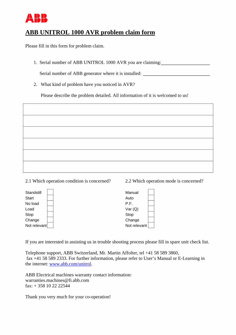
ABB UNITROL 1000 AVR problem claim form Please fill in this form for problem claim.
1. Serial number of ABB UNITROL 1000 AVR you are claiming: Serial number of ABB generator where it is installed:
2. What kind of problem have you noticed in AVR?
Please describe the problem detailed. All information of it is welcomed to us!
2.1 Which operation condition is concerned? 2.2 Which operation mode is concerned? Standstill Start No load Load Stop Change Not relevant
Manual Auto P.F. Var (Q) Stop Change Not relevant
If you are interested in assisting us in trouble shooting process please fill in spare unit check list. Telephone support, ABB Switzerland, Mr. Martin Affolter, tel +41 58 589 3860, fax +41 58 589 2333. For further information, please refer to User’s Manual or E-Learning in the internet: www.abb.com/unitrol. ABB Electrical machines warranty contact information: [email protected] fax: + 358 10 22 22544 Thank you very much for your co-operation!

1
UNITROL 1000 Spare unit installation check list for Wärtsilä Please fill in this formula for trouble shooting support / warranty claim handling. Mark N/A in irrelevant fields. Telephone support, ABB Switzerland, Mr. Martin Affolter, tel +41 58 589 3860, fax +41 58 589 2333. For further information, please refer to User’s Manual or E-Learning in the internet: www.abb.com/unitrol. General information Country: ___________________ Plant: ___________________ Generator Serial No: __________
Tech. Contact Person:__________________ Telephone No.: __________________ Email address: __________________
AVR Data
ID-Number: 3BHE_____________ Serial Number: _____________ Control Software: _____________ Panel Software: _____________ Status:_______ Sub-Status _______ Date of failure _____________
PCTools Provided Yes No PCTools Software version: _________ Under guarantee Yes No Running hours ________
Commissioning:
Made by: ____________________ Date: __________________
1.0 Fault description 1.1. What kind of problem have you noticed in AVR?
____________________________________________________ ____________________________________________________ ____________________________________________________
1.2. When (always/from time to time/how often/ Special situations) ____________________________________________________
1.3. Special events before the failure (over voltage, mechanical harm, etc.) ____________________________________________________
1.4. Special events after the failure (protection device active, etc.) ____________________________________________________

2
2.0 Which operation condition is concerned? Standstill Start No Load
Load Stop Not relevant
Change over from ______ to ______ Remarks: __________________ _________________
3.0 Which operation mode is concerned? Manual Auto P.F.
Var (Q) Stop Not relevant
Change over from ______ to ______ Remarks: __________________ _________________
5.0 Checking of the measurement circuits
5.1.Which measurement in the AVR is concerned? UM IM2 Ie P/Q/S Others: _____________ Please carry out the relevant measurements in (5.3-5.8) 5.2. Fault description: __________________________________________ __________________________________________ __________________________________________ 5.3. Measurement with the PCTools 5.4. Measurement on the Panel abs: ________ %: _________ abs: ________ %: _________ 5.5 UM Measurement at terminals U12: _________V U13: _________V U23: _________V 5.6 IM2 Measurement at terminals
NOTE: Never open a IM2 : ___________A running CT!!
5.6.1. Signal „Gen CB Closed Status“ OK (Panel / PCTools)? Terminal voltage / Relay Yes No Not known
Voltage at corresponding terminal (to GND): ____________V
5.7 Ie Measurement at shunt resistor (if available) Ie: __________
5.8 P/Q/S IM2 measuring OK? Yes No UM Measuring OK? Yes No
1 2 3
U12 U23
1 2 3
U13
16 A

3
6.0 Checking In- and Outputs 6.1 Which In- Output Number: ______ Function: ____________________ 6.2 Measurement at terminals at corresponding Terminal (against GND) ________V 6.3 Corresponding relay is working (if any) Yes No Not known 7.0 To check (If the problem was not mention above): 7.1 Field resistance Terminal 8/9: _______Ω 7.2 UPWR Terminal 10/11/(12) U10/11 ______ U11/12______ U10/12_______ 7.3 UAUX Terminal 13/14/(15) _______V 7.4 +Vdig Terminal 44/47 _______V 7.5 +Vref Terminal 18/25 _______V 7.6 -Vref Terminal 21/25 _______V Additional points to check: Fault message on the display: _________________________________________________ When failure occurs: _________________________________________________ Does other units have this problem too: ______________________________________ Display before failure: ________________________________________________ Display after failure: ________________________________________________ What additional measurements were done: ______________________________________ Can the field breaker be closed: ______________________________________ All MCB’s OK (e.g. -Q10, -Q11): ______________________________________ All connections and wires controlled: ______________________________________ Sketch of the relevant failure signals:

4
8.0 Plant Data (if not documented elsewhere) Machine nominal voltage, UMn ______ Machine nominal current, IMn _______ Machine nominal power, SMn ________ No load field current, Ieo ___________
Nominal field current, Ien ________ Field resistance, Rf ________ Nominal field voltage Uen ________ No load field voltage Ueo ________
9.0 Settings of the System Parameters Please attach Parameter file (.ini) from PCTools, saved online. If PCTools can not be used, please fill in the parameter list, found in User’s Manual. Please send following documents, if available
• Hardware Drawings UN1000 • Recordings from PCTools Oscilloscope • Oscillograms /Event list from plant monitoring system • Commissioning Report • Single line diagram of the plant
Thank You for your cooperation!

Instructionsfor Maintenance and Inspection
RH - EFEWI - E – 11.00
Slide Bearings Type EF
with self lubrication

Maintenance and Inspection
2 RH-EFEWI-E Version: 6 November, 2000 RENK AG Werk Hannover
RENK AKTIENGESELLSCHAFTWerk HannoverWeltausstellungsallee 21D - 30539 HannoverTelephone: (0511) 8601-0Telefax: (0511) 8601-266e-mail: [email protected]:\\www.renk.de
All rights reserved. Copy or reproduction without prior permission of RENK Aktiengesellschaft Hannoverprohibited.

EF with self lubrication
RENK AG Werk Hannover RH-EFEWI-E Version: 6 November, 2000 3
Contents
Bearing Coding................................................................................................................................................ 5
General Drawing of the Slide Bearing EF with self lubrication........................................................................ 7
General Drawing of the Loose Oil Ring ........................................................................................................... 9
General Drawing of the Floating Labyrinth Ring with Seal Carrier................................................................ 11
General Drawing of the Rigid Labyrinth Seal ................................................................................................ 13
General Drawing of the Baffle ....................................................................................................................... 15
General Drawing of the Dust Flinger ............................................................................................................. 17
1 Considerations for Use .......................................................................................................................... 19
2 Safety Instructions.................................................................................................................................. 20
3 Operating Instructions after Standstill ................................................................................................. 21
4 Maintenance Schedule........................................................................................................................... 22
5 Oil Change ............................................................................................................................................... 23
6 Dismantling of the Bearing .................................................................................................................... 24
6.1 Tools and equipment......................................................................................................................... 24
6.2 Use of lifting equipment .................................................................................................................... 24
6.3 Preparation for dismantling ............................................................................................................... 26
6.4 Dismantling of the shaft seal - outboard side ................................................................................... 27
6.4.1 Floating labyrinth seal (Type 10)................................................................................................. 27
6.4.2 Floating labyrinth seal with dust flinger (Type 11) ...................................................................... 27
6.4.3 Floating labyrinth seal with baffle (Type 12) ............................................................................... 27
6.4.4 Rigid labyrinth seal (Type 20) ..................................................................................................... 27
6.4.5 Rigid labyrinth seal with dust flinger (Type 21)........................................................................... 27
6.4.6 Rigid labyrinth seal with baffle (Type 22).................................................................................... 27
6.5 Dismantling of the top half of the housing ........................................................................................ 28
6.6 Removal of the top half of the shell................................................................................................... 28
6.6.1 Dismantling of the loose oil ring ................................................................................................. 28
6.6.2 Dismantling the machine side shaft seal.................................................................................... 29
6.7 Removal of the bottom half of the shell ............................................................................................ 29
6.8 Dismantling of the machine seal ....................................................................................................... 29
7 Cleaning and Checking of the Bearing................................................................................................. 30

Maintenance and Inspection
4 RH-EFEWI-E Version: 6 November, 2000 RENK AG Werk Hannover
8 Assembly of the Bearing ........................................................................................................................ 32
8.1 Fitting in the bottom half of the shell ................................................................................................. 32
8.2 Assembly of the shaft seal - machine-side ....................................................................................... 33
8.3 Installation of the loose oil ring.......................................................................................................... 35
8.4 Fitting in the top half of the shell ....................................................................................................... 36
8.5 Closing of the bearing ....................................................................................................................... 37
8.6 Assembly of the Seals - Outboard Side ............................................................................................ 39
8.6.1 Floating labyrinth seal (Type 10)................................................................................................. 39
8.6.2 Floating labyrinth seal with dust flinger (Type 11) ...................................................................... 43
8.6.3 Floating labyrinth seal with baffle (Type 12) ............................................................................... 44
8.6.4 Rigid labyrinth seal (Type 20) ..................................................................................................... 44
8.6.5 Rigid labyrinth seal with dust flinger (Type 21)........................................................................... 46
8.6.6 Rigid labyrinth seal with baffle (Type 22).................................................................................... 46
9 Starting Operation after Inspection ...................................................................................................... 47
10 Corrosion Protection for Longer Standstill Periods............................................................................ 48
11 Transport Protection .............................................................................................................................. 48
12 Glossary................................................................................................................................................... 49

EF with self lubrication
RENK AG Werk Hannover RH-EFEWI-E Version: 6 November, 2000 5
Bearing Coding

Maintenance and Inspection
6 RH-EFEWI-E Version: 6 November, 2000 © RENK AG Werk Hannover
Type
E
Housing
F - flange mountedbearing
Heat Dissipation
N - natural cooling
W - water cooling(finned cooler in oil sump )
Shape of Bore and Type ofLubrication
L - plain cylindrical bore withloose oil ring
Thrust part
Q - without thrust part(non-locating bearing )
B - plain sliding surfaces with oilgrooves (locating bearing)
E - taper land faces for one sense of rotation(locating bearing)
K - taper land faces for bothsenses of rotation(locating bearing)
Size - Diameter
9 80≤D≤100
11 100≤D≤125
14 125≤D≤160
18 160≤D≤200
22 200≤D≤250
28 250≤D≤315
Example for bearing coding:
E F N L Q 22-200 Type E slide bearing with flange mounted housing, natural coolingplain cylindrical bore with loose oil ring, non locating bearing without thrust part,size 22, diameter 200.
Shaft seals Type 10 - floating labyrinth seal (IP 44)Type 11 - floating labyrinth seal with dust flinger (IP 54)Type 12 - floating labyrinth seal with baffle (IP 55)
Type 20 - rigid labyrinth seal (IP 44)Type 21 - rigid labyrinth seal with dust flinger (IP 54)Type 22 - rigid labyrinth seal with baffle (IP 55)

self lubrication
RENK AG Werk Hannover RH-EFEE/WI-E Version: 6 November, 2000 7
General Drawing of the
Slide Bearing EF
with self lubrication

5
3
4
6 7 8 9
10
11
12
1
213
14
15
20
21
22
23
24
2627
19
17
18
16
25
xxx
xxx x
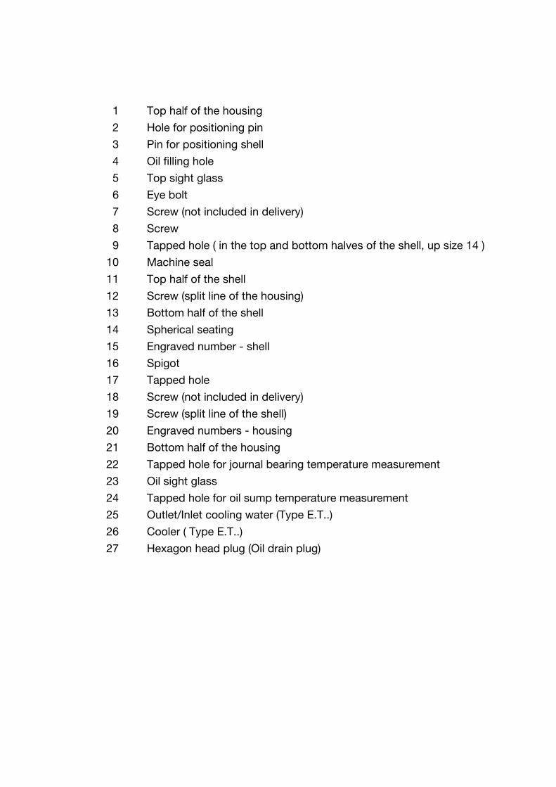
1 Top half of the housing
2 Hole for positioning pin
3 Pin for positioning shell
4 Oil filling hole
5 Top sight glass
6 Eye bolt
7 Screw (not included in delivery)
8 Screw
9 Tapped hole ( in the top and bottom halves of the shell, up size 14 )
10 Machine seal
11 Top half of the shell
12 Screw (split line of the housing)
13 Bottom half of the shell
14 Spherical seating
15 Engraved number - shell
16 Spigot
17 Tapped hole
18 Screw (not included in delivery)
19 Screw (split line of the shell)
20 Engraved numbers - housing
21 Bottom half of the housing
22 Tapped hole for journal bearing temperature measurement
23 Oil sight glass
24 Tapped hole for oil sump temperature measurement
25 Outlet/Inlet cooling water (Type E.T..)
26 Cooler ( Type E.T..)
27 Hexagon head plug (Oil drain plug)


self lubrication
RENK AG Werk Hannover RH-LSEE/WI-E Version: 6 November, 2000 9
General Drawing of the
Loose Oil Ring

33
34
35
36

33 Loose oil ring
34 Dowel pin
35 Hole
36 Screw


self lubrication
RENK AG Werk Hannover RH-SSEE/WI-E Version: 6 November, 2000 11
General Drawing of the
Floating Labyrinth Seal
with Seal Carrier

37
38
39
43
45
46
47
41
42
40
44
Bearing side
Outer view

37 Seal carrier - top half
38 Garter spring
39 Groove
40 Seal carrier - bottom half
41 Bottom half of the seal
42 Top half of the seal
43 Anti - rotation pin
44 Screw
45 Engraved number
46 Groove ( Type 11 )
47 Engraved number


self lubrication
RENK AG Werk Hannover RH-KDEE/WI-E Version: 6 November, 2000 13
General Drawing of the
Rigid Labyrinth Seal

48
49
50 (2x)
51
52
53
54

48 Rigid labyrinth seal - top half
49 Screw
50 Screw (split line)
51 Groove ( Type 21 )
52 Rigid labyrinth seal - bottom half
53 Engraved number
54 Engraved number


self lubrication
RENK AG Werk Hannover RH-DSEE/WI-E Version: 6 November, 2000 15
General Drawing
Baffle

55
56
57

55 Baffle - top half
56 Screw
57 Baffle - bottom half

self lubrication
RENK AG Werk Hannover RH-LREE/WI-E Version: 6 November, 2000 17
General Drawing of the
Dust Flinger

58
59 (2x)

58 Dust flinger
59 Screw (split line)


EF with self lubrication
RENK AG Werk Hannover RH-EFEWI-E Version: 6 November, 2000 19
1 Considerations for Use
The instructions for maintenance and inspection are addressed to qualified technical personnel(fitters, mechanic installers, mechanical engineers).
Read these instructions carefully before starting assembly.
Slide bearings of type EF are almost universally used in the engineering industry. Therefore it is notpossible to provide detailed information on all possible types and range of applications for thesebearing types. For instance, the position of the connection points for supply and monitoringequipment is determined by the place of application ( in the following called " installation " ).Please keep ready the guidelines with the technical documentation before starting assembly andoperation of the slide bearings.
Additional technical documentation with detailed information is supplied in the case of specialdesign bearings. Please contact RENK Export or Domestic Department for supplementaryinformation on bearings. Please indicate the bearing coding and the full reference number, too.
Following indications should be observed when reading these instructions.
Safety instructions are marked as follows:
Caution !Warning of dangers for personnel.Example: Warning of injury
Attention!Warning of damage for the bearing or installation.
Useful recommendations and additional information are framed.
This is how chapters, instructions or recommendations are marked when referring to a single typeor size of a bearing.
Example: Slide bearing type EF with water cooler
- Instruction follows.
• Beginning of an enumeration.
( ) This is how the different parts of a bearing as described in the general drawings ( numbers )are marked in the text.
− Use the enclosed check-list before starting assembly or operation. Copies available on request.− The check list provides the experienced mechanical fitters of RENK bearings with the
necessary instructions for installation and operation.
EFW..

Maintenance and Inspection
20 RH-EFEWI-E Version: 6 November, 2000 RENK AG Werk Hannover
2 Safety Instructions
Danger!The maintenance and inspection of the slide bearings should be carried out by:• persons nominated by the safety representative• persons correspondingly trained and instructed• persons with knowledge on appropriate standards, regulations and accident. prevention rules• persons with knowledge on first-aid measures and local rescue centers.
Warning of injury!Before starting work on the bearing:- Switch off the installation.- Make sure the installation is not in operation.Never lift or transport machines, etc.by the bearing eye bolts. These are only intendedfor assembly and dismantling of the bearing !
Warning of injury!Do not grab such heavy bearing parts as the housing during assembly or dismantlingwork. This could result in bruising or injury to hands !
Attention! All metal parts of a slide bearing consisting of top and bottom half such as the housing, shells,shaft seals are marked by engraved numbers. Fit together only the parts with the same number.
Attention! In case • the admissible bearing temperature exceeds 15 K
• inadmissible vibrations occur• unusual noises or odours are noticed• monitoring equipment triggers alarm
shut down the installation and inform the maintenance personnel in charge.
Attention!Do not operate the bearing below the transition speed values indicated in the bearing calculation,thus avoiding inadmissible operating conditions, which could lead to damage to the bearing.

EF with self lubrication
RENK AG Werk Hannover RH-EFEWI-E Version: 6 November, 2000 21
3 Operating Instructions after Standstill
− Clean the external parts of the bearing. Dust and dirt impede the radiation of the heat.− Check with the instructions for the use of the lubricating oil if an oil change is necessary.
Depending on the duration of the standstill an oil change is either prescribed or recommended.Carry out the oil change as indicated in Chapter 5.
− Check the oil level− If necessary, refill with lubricant by using the oil filling hole (4).
The refilling oil should be of the same type as already used.The oil level limits are as follows:
minimum oil level: bottom of the oil sight glass
maximum oil level: top of the oil sight glass
− Retighten the and screws (12), (8), (18) to the following torque rates:
Bearing Size 9 11 14 18 22 28
Torque [Nm] forµtot = 0,1 (lightly oiled)
69 69 170 330 570 1150
− Check the firm position of the top sight glass (5).− Check the firm position of the oil sight glass (23).
In case a thermo sensor or/and an oil sump thermometer are used:
− Check if they are well fitted (see also the manufacturer's instructions).− Retighten all screw plugs in the tapped holes (4), (22), (24) (27) to the necessary torque rates:
Screw plug threads G 3/8 G 1/2 G 3/4 G 1 G 1 1/4 G 1 1/2 G 2 G 2 1/2
Torque [Nm] for plugswith moulded on plasticseal
30 40 60 110 160 230 320 500
Torque [Nm] for plugswith elastic seal
34 60 85 130 240 300 330 410
− Check the functioning of the temperature monitoring equipment.
− Check the functioning of the cooler.
The bearing is now ready to work.
EFW..

Maintenance and Inspection
22 RH-EFEWI-E Version: 6 November, 2000 RENK AG Werk Hannover
4 Maintenance Schedule
Maintenance work Deadline
Exterior cleaning of the bearing every 100-1000 hours
Oil change Bearing in reversing operation every 5000 operating hours.Bearing in continous operation every 8.000 operating hours(please observe also the indications for the use of thelubricating oil).
Bearing inspection During prevention maintenance work for the installation.Immediately if:
• the bearing temperature exceeds 15 K over the indicatedvalue (see the EDP-calculations)
• unusual operating noises occur
• unusual changes of the lubricating oil become visible
• increased oil level in the case of bearing type EFW....

EF with self lubrication
RENK AG Werk Hannover RH-EFEWI-E Version: 6 November, 2000 23
5 Oil Change
Risk of pollution!Please observe the instructions for the use of the lubricating oil. The manufacturer can provideinformation on waste oil disposal.
− Shut down the installation and secure it against unintended operation.− Take all necesarry measures to collect the whole quantity of the lubricating oil.− Drain off the lubricating oil in still warm condition. Impurities and residues will thus be
scavenged.− Unscrew the hexagon head plug (27). Drain off the lubricating oil and collect it.
Attention! In case the lubricating oil contains unusual residues or is visibly changed, eliminate the causes. Ifnecessary, carry out an inspection.
− Tighten the hexagon head plug (27) to the following torque rates:
Bearing size 9 11 14 18 22 28
Torque [Nm] 30 30 30 40 60 60
− Remove the screw plug from the oil filling hole (4).
Attention! Make sure that no impurities get into the bearing.
− Use a lubricant with the viscosity indicated on the bearing type plate. Fill the lubricant throughthe oil filling hole (4) up to the middle point of the oil sight glass (23).The oil level limits are as follows:
minimum oil level: bottom of the oil sight glass
maximum oil level: top of the oil sight glass
Attention!• Not enough lubricant leads to temperature rises and thus to damage to the bearing.• Too much lubricant leads to leakages. In the case of bearings with lubrication by loose oil
ring too much lubricant could have a considerable breaking effect on the oil rings,thus leading to damage to the bearing.
− Tighten the screw plug into the oil filling hole (4) to the following torque rates:
Bearing size 9 11 14 18 22 28
Torque [Nm] 30 30 30 40 60 60

Maintenance and Inspection
24 RH-EFEWI-E Version: 6 November, 2000 RENK AG Werk Hannover
6 Dismantling of the Bearing
6.1 Tools and equipment
− Following tools and equipment are necessary:
• Allan key set• Wrenching key set• Open-jawed spanner set• Feeler gauges (up 0,05mm)• Caliper gauge• Emery paper, plain scraper• Oil stone• Lifting equipment• Permanent sealing compound (e.g. Curil T)• Clean (close weave) rags• Oil with the viscosity indicated (see bearing type plate)• Detergents• Liquid screw locking compound (e.g.LOCTITE 242)• Liquid sealing compound and Teflon tape.
6.2 Use of lifting equipment
Risk of injury!
Before transport or lifting check if the eye bolts are tight! Insecure eye bolts couldresult in bearing becoming loose.Before moving the bearing by the eye bolts make sure that the screws at the split lineare tightened, otherwise the bottom half of the bearing could become detached.
Make sure that the eye bolts are not exposed to bending stress, otherwise the boltscould break.
Follow exactly the instructions for the use of the lifting equipment.
− Use lifting equipment for following assembly and transport works:
Transport/Assembly of: Use lifting equipment for the following bearing sizes
Whole bearing unit 9-28
Top half of the housing 14-28
Bottom half of the housing 11-28
Shells 14-28
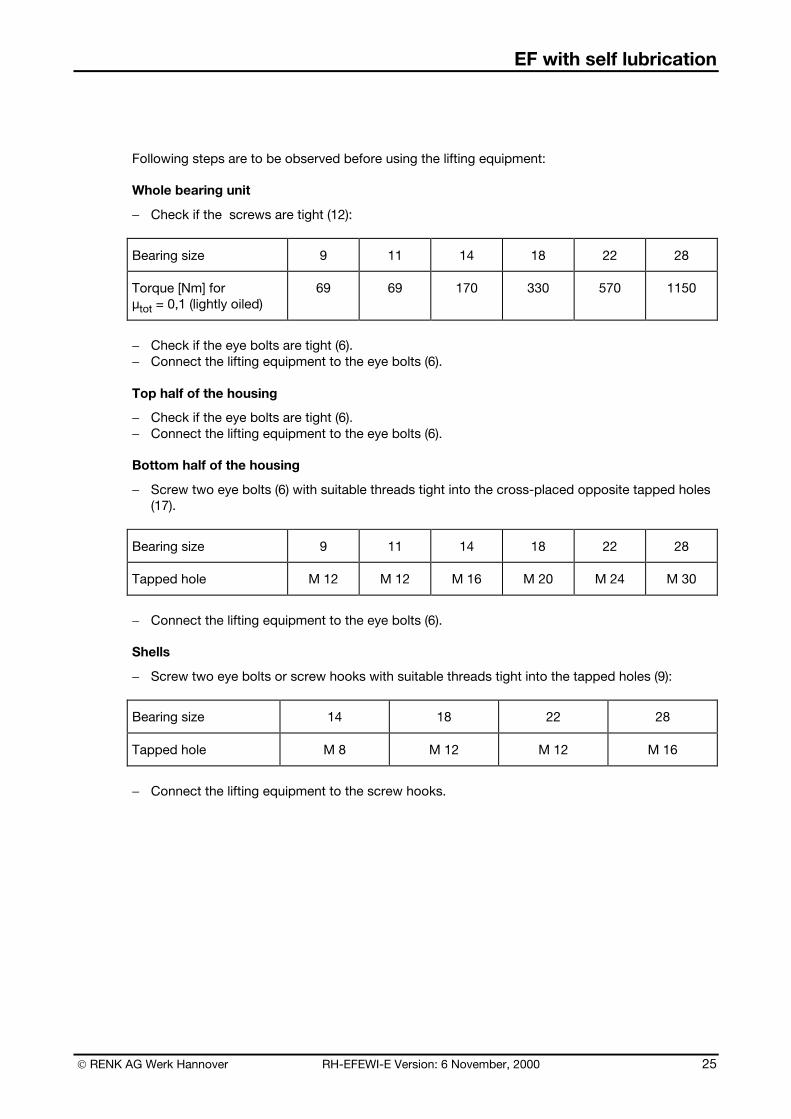
EF with self lubrication
RENK AG Werk Hannover RH-EFEWI-E Version: 6 November, 2000 25
Following steps are to be observed before using the lifting equipment:
Whole bearing unit
− Check if the screws are tight (12):
Bearing size 9 11 14 18 22 28
Torque [Nm] forµtot = 0,1 (lightly oiled)
69 69 170 330 570 1150
− Check if the eye bolts are tight (6).− Connect the lifting equipment to the eye bolts (6).
Top half of the housing
− Check if the eye bolts are tight (6).− Connect the lifting equipment to the eye bolts (6).
Bottom half of the housing
− Screw two eye bolts (6) with suitable threads tight into the cross-placed opposite tapped holes(17).
Bearing size 9 11 14 18 22 28
Tapped hole M 12 M 12 M 16 M 20 M 24 M 30
− Connect the lifting equipment to the eye bolts (6).
Shells
− Screw two eye bolts or screw hooks with suitable threads tight into the tapped holes (9):
Bearing size 14 18 22 28
Tapped hole M 8 M 12 M 12 M 16
− Connect the lifting equipment to the screw hooks.

Maintenance and Inspection
26 RH-EFEWI-E Version: 6 November, 2000 RENK AG Werk Hannover
6.3 Preparation for dismantling
Attention!Make sure that the work place is clean. Contamination and damages to the bearing, especially ofthe working surfaces, have a negative influence on the operating quality and could lead topremature damage.
Attention!Do not use any violence or force!
− Shut down the installation and ensure it against unintended operation.
− Interrupt the cooling water supply.
− Dismantle all thermo sensors from the connection holes.− Take all necessary measures to collect the lubricating oil.− Unscrew the hexagon head plug (27) and collect the lubricating oil.
Risk of pollution!Please observe the instructions for the use of the lubricating oil. The manufacturer can providenecessary information on waste oil disposal.
− Tighten the hexagon head plug (27) to the following torque rates
Bearing size 9 11 14 18 22 28
Torque (Nm] 30 30 30 40 60 60
EFW..

EF with self lubrication
RENK AG Werk Hannover RH-EFEWI-E Version: 6 November, 2000 27
6.4 Dismantling of the shaft seal - outboard side
− Dismantle the outboard side seals of the bearing.Proceed correspondingly to the seal type:
• Floating labyrinth seal (Type 10) Chapter 6.4.1• Floating labyrinth seal with dust flinger (Type 11) Chapter 6.4.2• Floating labyrinth seal with baffle (Type 12) Chapter 6.4.3
• Rigid labyrinth seal (Type 20) Chapter 6.4.4• Rigid labyrinth seal with dust flinger (Type 21) Chapter 6.4.5• Rigid labyrinth seal with baffle (Type 22) Chapter 6.4.6
6.4.1 Floating labyrinth seal (Type 10)
− Loosen all screws (44) and turn them off.− Remove simultaneously in axial direction both top half (37) and bottom half (40) of the seal
carrier from the housing.− Shift a little (about 20 mm) the top half (42) of the seal. Tilt it over carefully until the garter spring
(38) unbends.
Warning of injury!During dismantling of the floating labyrinth seal hold tight the garter spring (38) whichis under tension and could bounce back and lead to injury.
− Open the garter spring (38) and remove the bottom half of the seal (41) from the shaft.
6.4.2 Floating labyrinth seal with dust flinger (Type 11)
− Dismantle the dust flinger (58). Loosen the screws (59) and take out the dust flinger (58) fromthe groove (46) of the seal carrier. Remove both halves of the dust flinger.
− Go on as indicated for type 10 (see Chapter .4.1).
6.4.3 Floating labyrinth seal with baffle (Type 12)
− Unscrew both top (55) and bottom (57) halves of the baffle by untightening the screws (56).− Go on as indicated for type 10 (see Chapter 6.4.1).
6.4.4 Rigid labyrinth seal (Type 20)
− Loosen all screws (49) and take them out.− Take out the screws (50).− Remove simultaneously in axial direction both top (48) and bottom (52) halves of the rigid
labyrinth seal.
6.4.5 Rigid labyrinth seal with dust flinger (Type 21)
− Dismantle the dust flinger (58). Loosen the screw (59) and take out the dust flinger (58) from thegroove (51) of the rigid seal. Remove both halves of the dust flinger.
− Go on as indicated for type 20 (see Chapter 6.4.4).
6.4.6 Rigid labyrinth seal with baffle (Type 22)
− Unscrew the top half (55) and the bottom half (57) of the baffle by untightening the screws (56).− Go on as indicated for type 20 (see Chapter 6.4.4).
Type10
Type11
Type12
Type20
Type21
Type22

Maintenance and Inspection
28 RH-EFEWI-E Version: 6 November, 2000 RENK AG Werk Hannover
6.5 Dismantling of the top half of the housing
− Remove the screws (8).− Remove the screws (12).− Lift the top part of the housing (1) until the top part of the housing can be moved in axial line
over the shell, without touching it.
6.6 Removal of the top half of the shell
− Unscrew the screws (19) and lift the top half of the shell (11).
Attention!Do not damage the thrust and radial working surfaces.
Attention! In the case of insulated housings (white plastic insulating foil) avoid any jamming of the top half ofthe shell when you lift it up Jamming could lead to damage of the insulating foil in the bottom half of the housing.
6.6.1 Dismantling of the loose oil ring
− Open both split lines of the loose oil ring (33) by untightening and taking out the screws (36).Separate both halves of the loose oil ring (33) carefully without using any tools or other devices.
Illustration 1: Opening of the loose oil ring
To check the geometry of the loose oil ring put it together as follows:
− Press the positioning pin (34) into the hole (35).− Adjust both halves of the loose oil ring till the split lines match each other.− Tighten the screws (36).
II
33 33
I
33
36

EF with self lubrication
RENK AG Werk Hannover RH-EFEWI-E Version: 6 November, 2000 29
6.6.2 Dismantling the machine side shaft seal
− Shift a little (about 20 mm) the top half (42) of the seal. Tilt it over carefully until the garter spring(38) unbends.
Warning of injury!During dismantling of the floating labyrinth seal hold tight the garter spring (38) whichis under tension and could bounce back and lead to injury.
− Open the garter spring (38) and turn the bottom half of the seal (41) in opposite direction fromthe anti-rotation pin out of the integrated seal groove of the bottom half of the housing.
6.7 Removal of the bottom half of the shell
Attention!Make sure that all bearings mounted on a shaft line are opened. Loosen the screws at the split lineof the housings.
Attention!The lifting equipment should not come into contact with the seal and working surfaces of the shaft.
− Lift the shaft up to the point where shaft and bottom half of the shell (13) do not touch eachother any more. Protect the shaft against unintended movement.
− Turn the bottom half of the shell (13) out of the bottom half of the housing (21) and remove itfrom the shaft.
Attention!If the bottom half of the shell (13) is provided with metal tabs (28) do not remove them. Theyregulate the oil level in the oil pockets.
6.8 Dismantling of the machine seal
Usually it is not necessary to dismantle the machine seal (10) if maintenance works are carried out.
If due to certain reasons the split machine seal must be dismantled please observe that thisoperation can be carried out only from the inner part of the machine. Loosen the screws at thesplit line of the machine seal and remove the screws (7).
Non-split machine seals can be dismantled only after dismantling the machine shield or the shaftcompletely.
In the case the machine seal is equipped with a hamp packing, some visible changes can benoticed, such as : tallow excess, black colour of the seal due to temperature development. Even insuch cases it is not necessary to renew the hamp packing. Colour changes will appear with a newhamp packing too, until the seal clearance adjusts during operation.

Maintenance and Inspection
30 RH-EFEWI-E Version: 6 November, 2000 RENK AG Werk Hannover
7 Cleaning and Checking of the Bearing
Attention!Use only non-aggressive detergents such as for instance
• VALVOLINE 150• Alcaline cleaning compounds (pH-value 6 to 9, short reaction time).
Warning of injury!Please observe the instructions for the use of the detergents.
Attention!Never use cleaning wool or cloth. Residues of such materials left in the bearing could lead toexcessive temperatures.
− Clean the following parts thoroughly:
• top half of the housing (1)
• bottom half of the housing (21)
• top half of the shell (11)
• bottom half of the shell (13)
• sealing surfaces of the top half (37) and bottom half (40) of the seal carrier or of the rigidlabyrinth seal
• loose oil ring (33).
− Check the condition of the cooler (26).
In cases where the cooler (26) is incrusted with oil sludge:
− Dismantle the cooler. Remove the incrustation by using for instance a wire brush.− Install the cooler (26) into the bearing.
EFW..

EF with self lubrication
RENK AG Werk Hannover RH-EFEWI-E Version: 6 November, 2000 31
− Carry out a visual check of the wear condition of all bearing parts. The following graph providesinformation on the parts that must be replaced in case of wear.The right evaluation of the wearcondition, especially of the working surfaces of the shell, implies a lot of experience. If in doubt,replace the worn part with new ones.
Bearing part Wear condition
Maintenance procedures
Shell Scoring Bearing temperature before inspection:• not increased - no new shells• increased - new shells
White metal lining damaged New shell
Bow wave ridges New shells
Shaft seal Baffles broken or damaged New shaft seal
Loose oil ring Geometrical form ( roundness,flatness ) visibly changed
New loose oil ring
− Check the projection of the positioning pin (3) according to the values indicated below:
Bearing size 9 11 14 18 22 28
Projection of thepositioning pin (4) mm
7 8 10 12 14 16
In case the projection is less than indicated,
− drive the positioning pin (3) into the top half of the housing (1) until the indicated value isreached.
− Check the insulating layer of the spherical seating (14) of the top half (1) and bottom half (21) ofthe housing. In case of damage contact the RENK-sales agency in charge.
Size9-14
insulatedbearings

Maintenance and Inspection
32 RH-EFEWI-E Version: 6 November, 2000 RENK AG Werk Hannover
8 Assembly of the Bearing
Attention!Remove all impurities or other objects such as screws, nuts, etc. from inside the bearing. If leftinside they could lead to damage of the bearing. Cover up the opened bearing during work breaks.
Attention!Carry out all assembly operations without making use of force.
Attention!Secure all screws of the housing, flange and at the split line with a liquid screw locking compound(e.g.LOCTITE 242).
8.1 Fitting in the bottom half of the shell
Attention!Mounting the bottom half of the shell (not marked with an arrow) correctly will ease the assemblyof the top half shell (marked with an arrow) (see chapter 8.4).
− Apply some lubricant to the spherical seating (14) in the bottom half of the housing (21) and tothe working surfaces of the shaft. Use the same type of lubricant as indicated for bearingoperation( see type plate ).
− Place the bottom half of the shell (13) on the working surface of the shaft. Turn the bottom halfof the shell (13) into the bottom half of the housing (21) with the split line surfaces of both halvesin true alignment.
In case the bottom half of the shell doesn’t turn in easily, check the position of the shaft and thealignment of the housing
Attention!These operations should be carried out most carefully. The thrust parts of the bottom shell mustnot be damaged.
− Lower down the shaft till it sits on the bottom half of the shell (13).
EF..E
EF..B, EF..K, EF..E

EF with self lubrication
RENK AG Werk Hannover RH-EFEWI-E Version: 6 November, 2000 33
8.2 Assembly of the shaft seal - machine-side
The machine-side shaft seal is, as standard, a floating labyrinth seal. The integrated seal groove isin the top and bottom halves of the housing.
Warning of injury!During assembly hold the garter spring ends (38) securely to avoid them suddenlyreleasing and causing possible injury!
Check the movement of the floating labyrinth seal on the shaft in the seal area outside the housing:
− Put the garter spring (38) around the shaft and hook both ends into each other.− Put both halves of the seal (41), (42) in their place on the shaft.− Put the garter spring (38) into the groove (39).− Turn the floating labyrinth seal on the shaft.
Attention!The floating labyrinth seal should turn easily on the shaft. A jammed seal could lead to overheatingduring operation and even to shaft wear.If the floating labyrinth seal jams,- dismantle the seal and- remove the worn parts of the seal carefully, by using emery paper or a plain scraper.
− Dismantle the floating labyrinth seal.− Apply Curil T to the guide surfaces of the integrated seal groove in the bottom half of the
housing.
Illustration 2: Applikation of Curil T to the integrated seal groove
21

Maintenance and Inspection
34 RH-EFEWI-E Version: 6 November, 2000 RENK AG Werk Hannover
− Apply a uniform layer of Curil T to the seal surfaces and to the split line surfaces of both halvesof the seal (41), (42).
Illustration 3: Application of Curil T to the floating labyrinth seal
Please observe the instructions for the use of Curil T.
− Place the bottom half of the seal (41) with the labyrinths onto the shaft.− The oil return holes at the bearing side must be clear and open.− Turn the seal in opposite direction from the anti-rotation pin into the groove of the housing until
the split lines of the bottom half of the housing and the bottom half of the seal match eachother.
− Remove the rests of Curil T.− Push the garter spring into the integrated seal groove between the bottom half of the housing
and the seal until both ends jut out from the split line.− Place the top half of the seal with the cam facing the inside of the bearing on the bottom half of
the seal.− Stretch the garter spring till both ends can be hooked.
41

EF with self lubrication
RENK AG Werk Hannover RH-EFEWI-E Version: 6 November, 2000 35
8.3 Installation of the loose oil ring
− Open both split lines of the loose oil ring (33) by untightening and removing the screws (36).Separate both halves of the loose oil ring (33) carefully without using any tools or other devices.
Illustration:4 Opening of the loose oil ring
− Place both halves of the loose oil ring into the shell groove (13) around the shaft. Press thepositioning pin (34) of each split line into the corresponding hole (35).
− Adjust both halves of the loose oil ring till the split lines match each other.
llustration 5: Installation of the loose oil ring
− Tighten the screws (36) to the following torque rates:
Bearing size 9 11 14 18 22 28
Torque [Nm] 1,4 1,4 1,4 2,7 2,7 2,7
II
33 33
I
33
36
33
34
33
21
13

Maintenance and Inspection
36 RH-EFEWI-E Version: 6 November, 2000 RENK AG Werk Hannover
8.4 Fitting in the top half of the shell
− Apply some lubricant to the working surfaces of the shaft. Use the same type of lubricant asindicated for bearing operation (see type plate).
− Check if the engraved numbers (15) on the bottom and top halves of the shell correspond.− Place the top half of the shell (11) on the shaft; both engraved numbers (15) should be on the
same side.
Attention!An incorrectly placed shell could jam the shaft thus leading to the damage of both shaft andbearing.
Attention!Place the top half of the shell carefully on the shaft. The thrust parts of the top half of the shellshould not be damaged.
In the case of bearings arranged for insulation monitoring, connect the black cable for insulationmonitoring to the shell.
According to the bearing type, there are two possibilities of connection.
1. The black cable is provided with a cable connector.
− Plug the cable with the cable connector into the counterpart available on the top of the shell.− Lead the cable through the cable gland in the bottom half of the housing and out of the
bearing.− Tighten the cable gland oil-tight.
2. The black cable is provided with an eyelet.
− Fasten the cable with the eyelet to the split line of the shell, by using one of the shell joint bolts.− Lead the cable through the cable gland in the bottom half of the housing and out of the
bearing.− Tighten the cable gland oil-tight.
− Tighten up the screws (19) to the following torque rates:
Bearing size 9 11 14 18 22 28
Torque [Nm] 8 8 20 69 69 170
− Check the split line of the shell by using a feeler gauge. The split line gap should be less than0,05 mm. If the split line is greater than this, dismantle both top and bottom (11),(13) halves ofthe shell. Rework the split line surfaces of the top half (11) and bottom half (13) of the shell withan oil stone.
− Check the mobility of the loose oil ring (33).
A guide bush in the top half of the shell secures the function of the loose oil ring.
− Check the mobility of the loose oil ring (33) in the guide bush.
EF..B, EF..K, EF..E
insulatedbearings
EF.L. MarineBearing

EF with self lubrication
RENK AG Werk Hannover RH-EFEWI-E Version: 6 November, 2000 37
Shells with taper land faces suitable only for one direction of rotation are marked with an arrow onthe top half shell, which indicates the sense of rotation of the shaft.
The arrow indicates the allowed direction of shaft rotation after completion of the bearingassembly.
− Before mounting the top half of the housing check that the proposed direction of rotation of theshaft corresponds to the direction indicated by the arrow on the top half of the shell.
− If the directions match, continue the assembly of the bearing.− If the directions do not match, the shell must be disassembled, re-aligned and mounted again.
Attention! A wrongly placed shell, without observance of the direction of rotation of the shaft, impairs theoperational safety of the bearing.
8.5 Closing of the bearing
− Check the true alignment of the shell (11), (13) and bottom half (21) of the housing.
The positioning pin (3) in the top half of the housing fits in the corresponding hole (2). The shell isthus placed into its right position.
− Check if the engraved numbers (20) on the top and bottom halves of the housing correspond.− Clean the split line surfaces of the top and bottom halves (1), (21) of the housing.− Apply Curil T over the whole surface of the split line of the bottom half (21) of the housing.
Please observe the instructions for the use of Curil T.
− Place the top half of the housing carefully into the machine shield, without touching the seals orthe shell.
− Lower the top half of the housing (1) vertically on the bottom half of the housing (21). Lower thetop half of the housing (1) till the split line of the housing is not visible any more.
− Gently hit the bottom half of the housing (21) with a nylon hammer, thus ensuring the alignmentof the spherical seating.
− Insert the screws (12). Tighten them hand-tight.− Insert the screws (8). Tighten them to the following torque rates:
Bearing size 9 11 14 18 22 28
Torque [Nm]µtot = 0,1 (lightly oiled)
69 69 170 330 570 1150
− Tighten the screws (12) of the housing crosswise to the same torque rates.
EF..E

Maintenance and Inspection
38 RH-EFEWI-E Version: 6 November, 2000 RENK AG Werk Hannover
Insulation monitoring
In the case of electric insulated bearings provided with insulation monitoring, the cable coming outof the housing must be connected in a professional manner.
According to the type supplied, please follow the assembly instructions given below.
a) The cable is very short and provided with a further cable connector at the end of it.This cable is ready for connection to the housing.The bottom half of the housing is provided with the counterpart.
− Plug the cable connector into the counterpart.
Attention! This connection bypasses the electrical insulation of the bearing. In the case of electric machines, make sure at least one bearing is electrically insulated.
To check the electrical insulation, interrupt the connection cable - housing. Check the electricalresistance with a suitable measuring instrument. Make sure that both bearings and the couplingare electrically insulated.
b) The cable has a free end. In this case the customer has to make the connection.
Attention! If only one bearing is insulated, the end of the cable must not be earthed.
Any further connection depends on the customer’s requirements related to the insulationmonitoring and can not therefore be described here.
insulatedbearings

EF with self lubrication
RENK AG Werk Hannover RH-EFEWI-E Version: 6 November, 2000 39
8.6 Assembly of the Seals - Outboard Side
− Assemble the outboard side seals.Proceed according to the seal type used:
• Floating labyrinth seal (Type 10) Chapter 8.6.1• Floating labyrinth seal with dust flinger (Type 11) Chapter 8.6.2• Floating labyrinth seal with baffle (Type 12) Chapter 8.6.3
• Rigid labyrinth seal (Type 20) Chapter 8.6.4• Rigid labyrinth seal with dust flinger (Type 21) Chapter 8.6.5• Rigid labyrinth seal with baffle (Type 22) Chapter 8.6.6
8.6.1 Floating labyrinth seal (Type 10)
Warning of injury!During assembly hold the garter spring ends (38) securely to avoid them suddenlyreleasing and causing possible injury!
Check the movement of the floating labyrinth seal on the shaft in the seal area outside the housing.
− Put the garter spring (38) around the shaft and hook both ends into each other.− Put both halves of the seal (41), (42) in their place on the shaft.− Put the garter spring (38) into the groove (39).− Turn the floating labyrinth seal on the shaft.
Attention!The floating labyrinth seal should turn easily on the shaft. A jammed seal could lead to overheatingduring operation and even to shaft wear.If the floating labyrinth seal jams,- dismantle the seal and- remove the worn parts of the seal carefully, by using emery paper or a plain scraper.
− Dismantle the floating labyrinth seal.
Type10

Maintenance and Inspection
40 RH-EFEWI-E Version: 6 November, 2000 RENK AG Werk Hannover
− Apply a uniform layer of Curil T to the guide surfaces and to the split line surfaces of bothhalves of the seal (41), (42).
Please observe the instructions for the use of Curil T.
Illustration 6: Application of Curil T to the floating labyrinth seal
− Press the bottom half of the seal (41) against the shaft.− Place the top half of the seal (42) on the shaft and align both halves of the seal to each other.− Place the garter spring (38) into the groove (39) and stretch until both ends can be hooked.
Illustration 7: Assembly of the floating labyrinth seal
41
38 41 21
14243

EF with self lubrication
RENK AG Werk Hannover RH-EFEWI-E Version: 6 November, 2000 41
− Place in true alignment the split line of the floating labyrinth seal and the split line of the sealcarrier.
− Check that both engraved numbers (45) and (47) on top and bottom halves of the seal carrier(37), (40) correspond.
− Clean the following parts:
• the seal surfaces of the top (37) and bottom (40) half of the seal carrier (the groove of thefloating labyrinth seal, the flange surfaces)
• the split line surfaces of the top (37) and bottom (40) half of the seal carrier• the flange surfaces of the housing.
− Apply a uniform layer of Curil T to:
• the lateral surfaces of the groove at the top (37) and bottom (40) half of the seal carrier• the flange surfaces of the top (37) and bottom (40) half of the seal carrier• the split line surfaces of the bottom half of the seal carrier (40).
Please observe the instructions for the use of Curil T.
Illustration 8: Application of Curil T to the seal carrier
40

Maintenance and Inspection
42 RH-EFEWI-E Version: 6 November, 2000 RENK AG Werk Hannover
− Place the top half of the seal carrier (37) on the top half of the seal (42). Press the bottom half(40) of the seal carrier against it. Push the shaft seal completely into the housing.
Illustration 9: Assembly of the seal carrier
− Place in true alignment the split lines of the seal carrier and the housing.− Tighten up the screws (44) to the following torque rates:
Bearing size 9 11 14 18 22 28
Torque [Nm] 8 8 8 20 20 20
37
43
42

EF with self lubrication
RENK AG Werk Hannover RH-EFEWI-E Version: 6 November, 2000 43
8.6.2 Floating labyrinth seal with dust flinger (Type 11)
− Assemble the floating labyrinth seal with dust flinger as described in Chapter 8.6.1, Floatinglabyrinth seal type 10.
− Place both halves of the dust flinger (58) in front of the shaft seal around the shaft. Looselyscrew in the screws (59).
Illustration 10: Clearance between dust flinger and seal carrier
− Push the dust flinger (58) into the groove (46) of the seal carrier.− Set the clearance "e" at the following figure around the whole unit:
maximum longitudinal extension of the shaft in operation + 1 mm
(Parameters indicated in the Technical Documentation of the Installation).
− Tighten up the screws (59) to the following torque rates:
Seal diameter [mm] 80-140 >140
Torque [Nm] 7 18
− Push the dust flinger (58) into the groove (46) of the seal carrier.− Set the clearance "e" at 1 mm around the whole unit.− Tighten the screws (59) to the following torque rates:
Seal diameter [mm] 80-140 >140
Torque [Nm] 7 18
Type11
e
58 37
46
EF..Q
EF..B, EF..E, EF..K

Maintenance and Inspection
44 RH-EFEWI-E Version: 6 November, 2000 RENK AG Werk Hannover
8.6.3 Floating labyrinth seal with baffle (Type 12)
− Assemble the floating labyrinth seal with baffle as in Chapter 8.6.1, Type 10.− Apply a uniform layer of Curil T to the flange surfaces of the top half (55) and bottom half (57) of
the baffle.− Screw • the top half of the baffle (55) onto the top half of the seal carrier (37)
• the bottom half of the baffle (57) onto the bottom half of the seal carrier (40).− Tighten the screws (56) to the following torque rates:
Seal diameter [mm] 80-140 >140
Torque [Nm] 4 10
8.6.4 Rigid labyrinth seal (Type 20)
− Check if the engraved numbers (53) and (54) on the bottom half (52) and top half (48) of the rigidlabyrinth seal correspond.
− Clean• the flange surfaces of the top half (48) and bottom half (52) of the rigid labyrinth seal• the split line surfaces of the top half (48) and bottom half (52) of the rigid labyrinth seal• the flange surfaces of the housing.
− Apply a uniform layer of Curil T to the following parts:• the flange surfaces of the top half (48) and bottom half (52) of the rigid labyrinth seal• the split lines of the bottom half (52) of the rigid labyrinth seal.
Please observe the instructions for the use of Curil T.
Illustration 11: Application of Curil T to the rigid labyrinth seal
Type12
Type20
52

EF with self lubrication
RENK AG Werk Hannover RH-EFEWI-E Version: 6 November, 2000 45
− Place the top half (48) of the rigid labyrinth seal on the shaft and press slightly the bottom half(52) of the rigid labyrinth seal from below against it. Lightly push the rigid labyrinth sealcompletely into the housing.
− Tighten the screws (50).− Place in parallel alignment the split line of the rigid labyrinth seal and the split line of the
housing. Press the rigid labyrinth seal slightly from below against the shaft. Adjust the rigidlabyrinth seal in such a way that the clearance "f" between the shaft and the rigid labyrinth sealat both split lines has the same figure.
Illustration 12: Alignment of the rigid labyrinth seal
− Tighten the screws (49) to the following torque rates:
Bearing size 9 11 14 18 22 28
Torque [Nm] 8 8 8 20 20 20
f f
1
21
48
52

Maintenance and Inspection
46 RH-EFEWI-E Version: 6 November, 2000 RENK AG Werk Hannover
8.6.5 Rigid labyrinth seal with dust flinger (Type 21)
− Assemble the rigid labyrinth seal with dust flinger as indicated in Chapter 8.6.4, Type 20.− Place both halves of the dust flinger (58) round the shaft, in front of the rigid labyrinth seal.
Mount the screws (59) loose.
Illustration 13: Clearance between dust flinger and rigid labyrinth seal
− Push the dust flinger (58) into the groove (51) of the rigid labyrinth seal.− Set the clearance "e" at the following figure around the whole unit:
maximum longitudinal extension of the shaft in operation + 1 mm
(Parameters are indicated in the Technical Documentation of the Installation).
− Tighten the screws (59) to the following torque rates:
Seal diameter [mm] 80-140 >140
Torque [Nm] 7 18
− Push the dust flinger (58) into the groove (51) of the rigid labyrinth seal.− Set the clearance "e" at 1 mm around the whole unit.− Tighten the screws (59) to the following torque rates:
Seal diameter [mm] 80-140 >140
Torque [Nm] 7 18
8.6.6 Rigid labyrinth seal with baffle (Type 22)
− Assemble the rigid labyrinth seal with baffle as described in Chapter 8.6.4.− Apply a uniform layer of Curil T to the flange surfaces of the top half (55) and bottom half (57) of
the baffle.− Tighten • the top half of the baffle (55) to the top half (48) of the rigid labyrinth seal
• the bottom half of the baffle (57) to the bottom half (52) of the rigid labyrinth seal.− Tighten the screws (56) to the following torque rates:
Seal diameter [mm] 80-140 >140
Torque [Nm] 4 10
Type21
e
58 48
51
EF..Q
EF..B, EF..E, EF..K
Type22

EF with self lubrication
RENK AG Werk Hannover RH-EFEWI-E Version: 6 November, 2000 47
9 Starting Operation after Inspection
− Fit the thermo sensors for:• temperature measurement of the journal part in the tapped holes (22)
− Retighten all screw plugs in the tapped holes (22), (24), (27), (29) to the following torque rates:
Screw plug threads G 3/8 G 1/2 G 3/4 G 1 G 1 1/4 G 1 1/2 G 2 G 2 1/2
Torque [Nm] for plugswith moulded on plasticseal
30 40 60 110 160 230 320 500
Torque [Nm] for plugswith elastic seal
34 60 85 130 240 300 330 410
− Check that the top sight glass (5) is tight.− Check that the oil sight glass (23) is tight, the screws should be hand-tight.
− Carry out a visual check of the assembled bearing.
− Remove the screw plugs from the oil filling hole (4).
Attention! Make sure that no impurities get into the bearing.
− Use a lubricant with the viscosity indicated on the bearing type plate. Fill the lubricant throughthe oil filling hole (4) up to the middle point of the oil sight glass (22).The oil level limits are as follows:
minimum oil level: bottom of the oil sight glass
maximum oil level: top of the oil sight glass
Attention!• Not enough lubricant leads to temperature rises and thus to damages to the bearing.• Too much lubricant leads to leakages. In the case of bearings with lubrication by loose oil
ring too much lubricant could have a considerable breaking effect on the oil rings,thus leading to damages to the bearing.
− Tighten the screw plug into the oil filling hole (4) to the following torque rates:
Bearing size 9 11 14 18 22 28
Torque [Nm] 30 30 30 40 60 60
− Check that the temperature monitoring equipment works.
− Start operating the cooling water supply system and check its functioning.
The bearing is ready for operation.
EFW..

Maintenance and Inspection
48 RH-EFEWI-E Version: 6 November, 2000 RENK AG Werk Hannover
− Supervise the bearing during the trial run ( 5 - 10 operating hours ).Pay special attention to:
• oil level• bearing temperature• sliding noises of the shaft seals• tightness• occurrence of inadmissible vibrations.
Attention!If the bearing temperature exceeds the calculated value by 15 K (see the EDP-bearingcalculations) stop the installation immediately. Carry out an inspection of the bearing and find outthe causes.
10 Corrosion Protection for Longer Standstill Periods
If you want to protect the bearing mounted on an installation against corrosion proceed as follows:
− Dismantle the bearing (see Chapter 6).− Clean the bearing (see Chapter 7).− Paint or spray the top half of the shell (11), the bottom half of the shell (13) and the shaft with
TECTYL 511.− Assemble the bearing (see Chapter 8).− Close all tapped holes with screw plugs.− Seal the gaps between • shaft seal and housing
• shaft seal and shaftby using a self-adhesive, permanent tape.
− Remove the top sight glass (5). Spray some anti-corrosive such as TECTYL 511 or VALVOLINEinto the bearing.
− Put a bag of dessicant (silicate gel) inside. The dessicant absorbs the humidity and prevents theformation of condensation water inside the bearing.
− Close the bearing tight with the top sight glass (5).
In case the standstill period is longer than 1/2 year:
− Repeat the preservation procedures.− Put a new bag of dessicant into the bearing.
In case the standstill period lasts more years:
− Dismantle the shells.− Preserve and store the bearing parts.
11 Transport Protection
In case of a machine equipped with slide bearings of type EF:
− Carry out the corrosion protection as described in Chapter 10 and apply enough lubricant onthe working surfaces of the bearing.
− Secure the shaft against thrust and radial movements during transportation

EF with self lubrication
RENK AG Werk Hannover RH-EFEWI-E Version: 6 November, 2000 49
12 Glossary
Baffle With bearing types 10 and 20 the baffles are assembled externally in front of the shaftseals. The baffle, made of reinforced polyamide, protects the bearing from dust andwater.
Rigid labyrinth seal The rigid labyrinth seal (type 20) is used with slide bearings type E with high oilthroughput.It corresponds to the protective system IP44 and is made of an aluminiumalloy.The rigid labyrinth seal is built of two halves, flanged at the housing.The labyrinths thatwipe out the lubricant are arranged into two groups.The first two labyrinths , installedinside keep back most of the lubricant. Five further labyrinths protect the bearing fromoutside.They prevent the lubricant overflow and the ingress of impurities.The overflowlubricant is collected into a chamber between the both groups of labyrinths.Throughthe return bores the lubricant flows back into the bearing.
Spherical seating The spherical seating is a special feature enabling the alignment of the shell in thehousing.The shell is seated on two spherical seatings. The advantages of the sphericalseating are:• easy at assembly• good heat transfer from the shell to the housing• suitable for such applications with high thrust or journal loads.
Dust flinger In the case of bearing types 10 and 20 a light alloy ring is clamped on the shaft in frontof the shaft.This ring fits into a groove in the seal carrier or the rigid labyrinth seal, thusbuilding a labyrinth. The labyrinth protects the shaft exit against low pressure that couldotherwise " absorb " the lubricant. Low pressure occurs for instance in the case ofrotating discs, such as couplings or cooling discs.
Floating labyrinth The floating labyrinth seal (type 10) in the seal carrier is used as a shaft seal in the caseseal of bearings type E operating under normal conditions. It prevents the lubricant and
lubricant mist coming out and the ingress of impurities. The floating seal has a highcapacity of resistance to wear. It is made of a high-performance, high temperaturestability and electrically insulated plastic material.The floating seal consists of twohalves held together by a garter spring. Both ends of the spring are hooked together. Inthe case of slide bearings type EM the floating seal is mounted into a two-piece sealcarrier. The groove allows for radial movement of up to 1 mm. The seal is thusinsensitive to shaft radial displacement or deflection. The sealing effect is produced bythe baffles wiping off the lubricant from the shaft. The lubricant flows back into thebearing via oil return opening.
Machine seal In the case of the flange mounted bearings, the machine seal reduces the influence ofpositive and negative pressure in the machine thus preventing leakages at the innerseal area. The space between the machine seal and the bearing housing must alwaysbe vented to atmospheric pressure. The size of the gap between shaft and machineseal influences the sealing effect.

User’s Manual
Serial no.ABB ref.Project:
ABB
Synchronous MachineAMG 1120MM10DSE
45771693020HE401
July 2004 Grupo Punta Cana
8.Test Reports

User’s Manual
Serial no.ABB ref.Project:
ABB
Synchronous MachineAMG 1120MM10DSE
45771693020HE401
July 2004 Grupo Punta Cana
ContentsTest Reports

Test report for synchronous machines
Customer
Date
Serial nrWork nr:Machine
Project
WÄRTSILÄ FINLAND OY
AMG 1120MM10 DSE
Grupo Punta Cana
4577169
P/04007-Grupo Punta Cana
3020HE401
Order reference
3.6.2004
Approved on the behalf of manufacturer
Jukka Siuko
ABB Oy, Electrical MachinesVisiting AddressStrömbergintie 1HELSINKI
Telefax(Group)+358 10 22 22330Telefax(Test floor)+358 10 22 23692
Postal AddressP.O.Box 186FIN-00381 HELSINKIFinland
TEST REPORT

PageMachine
Work nr: Serial nr Revision
Approved
Customer
ProjectGrupo Punta Cana
4577169
AMG 1120MM10 DSE
P/04007-Grupo Punta Cana A
WÄRTSILÄ FINLAND OYOrder reference
3020HE401Report rev:
A
2
Jukka Siuko
p.f.In [A] Im [A]Um [V]Un [V] f [Hz]Usage Sn/Pn[kVA]Conn Direction n [rpm]
RATINGS
FNoneIM 1101
50 °CF
IEC
IP 23Ambient temp. maxTemperature classInsulation classStandards Classification society
S1
MountingProtection classDuty
8713 403 0.80 60.0 63 8.4 <== 720Generator Y 12470Table of contents / Test Program
Visual inspection1)Air gap measurement and bearing clearance2)Insulation resistances before tests3)Resistance measurement of windings and elements4)Direction of rotation, checking of phase sequence5)First running6)No-load point7)Short-circuit point8)No-load and short circuit curve, U1 = f(Im) and I1 = f(Im)9)Tests with regulator10)Overspeed test11)Vibration measurement after overspeed12)High voltage test13)Insulation resistances with PI14)
Appendices: 1) Tests with regulator_Basic settings2) Tests with regulator_Voltage build up and regulation at no-load
TEST REPORT

PageMachine
Work nr: Serial nr Revision
Approved
Customer
ProjectGrupo Punta Cana
4577169
AMG 1120MM10 DSE
P/04007-Grupo Punta Cana A
WÄRTSILÄ FINLAND OYOrder reference
3020HE401Report rev:
A
3
Jukka Siuko
Visual inspection
Version Notes
1)
A OK
9.22.4 3.1
5.000.329.0
2)
0.3240.5
Airgap
MachineExciter
Min [mm] Max [mm]Bearing clearance Axial play ET
DN.D
[mm] [mm] [mm]
Air gap measurement and bearing clearance
Resistances of detectors and space heaters
Terminal box Terminals Position R [ohm] Detector25.0 °CT =
151.21HE1 - 1HE2B3A Space heaters109.7 Pt-1001R1 - 1R2B3A Stator winding U109.6 Pt-1002R1 - 1R2B3A Stator winding V109.6 Pt-1003R1 - 3R2B3A Stator winding W109.8 Pt-1004R1 - 4R2B3A Stator winding U (spare)109.9 Pt-1005R1 - 5R2B3A Stator winding V (spare)109.8 Pt-1006R1 - 6R2B3A Stator winding W (spare)109.8 Pt-10030R1 - 30R2B3A Bearing D-end109.4 Pt-10040R1 - 40R2B3A Bearing N.D-end
Insulation resistances before tests
R [Mohm] t1 [s]U [V]25°CT =
Winding
3)
5200 601000Stator25400 601000Rotor
Temperature detectors
500500
500Space heater
StatorBearing
Auxiliaries
3660007500
324000
Exciter 57500 1000
Resistance measurement of windings and elements
Ruv [ohm] Rvw [ohm]Ruw [ohm]Armature windings
Resistances of windingsT =
4)
20 °C
0.139190.13907Stator 0.138990.78771Rotor
0.01975 0.01976 0.019745.44533Stator
Rotor:
Exciter
TEST REPORT

PageMachine
Work nr: Serial nr Revision
Approved
Customer
ProjectGrupo Punta Cana
4577169
AMG 1120MM10 DSE
P/04007-Grupo Punta Cana A
WÄRTSILÄ FINLAND OYOrder reference
3020HE401Report rev:
A
4
Jukka Siuko
OKNotes
First running6)
Result
5) Direction of rotation, checking of phase sequence
U-V-W | L3-L2-L1 | <<< (CCW)
No-load point
n [rpm] U1 [V] Im [A] Ir [A]T [°C]
7)
65.1 12493 3.00 80.0720Voltage balancesStator Uuv [V] Uuw [V] Uvw [V]
12491 12499 124951Notes
Short-circuit pointn [rpm] Im [A] Ir [A]T [°C] I1 [A]
8)
49.4 96.2403.1 3.60720
Stator Iu [A] Iv [A] Iw [A]Current balances
404 404 4021
TEST REPORT

PageMachine
Work nr: Serial nr Revision
Approved
Customer
ProjectGrupo Punta Cana
4577169
AMG 1120MM10 DSE
P/04007-Grupo Punta Cana A
WÄRTSILÄ FINLAND OYOrder reference
3020HE401Report rev:
A
5
Jukka Siuko
65.1 °C720 rpm
49.4 °C720 rpm
T =n =
n =T =
No-load curve
Im [A] I1 [p.u.]
U1 [p.u.]Im [A]
3.50
6.20
1.602.36
4.14
2.62
1.04
3.00
1.31
0.530.650.76
0.000.40
1.35
1.05
1.20
0.700.90
1.10
0.95
0.50
1.00
0.60
0.300.350.39
0.080.25
16.46
2.64
3.99
0.00
3.60
0.751.69
1.50
0.75
1.10
0.05
1.00
0.250.50
5.63
Short-circuit curve
Ratings
n =
U1 =I1 =
720 rpm
12470 V403 A
U1 I1
Im [A]2520151050
U1
[p.u
.], I
1 [p
.u]
1.6
1.4
1.2
1.0
0.8
0.6
0.4
0.2
0.0
9) No-load and short circuit curve, U1 = f(Im) and I1 = f(Im)
TEST REPORT

PageMachine
Work nr: Serial nr Revision
Approved
Customer
ProjectGrupo Punta Cana
4577169
AMG 1120MM10 DSE
P/04007-Grupo Punta Cana A
WÄRTSILÄ FINLAND OYOrder reference
3020HE401Report rev:
A
6
Jukka Siuko
UNITROL 1000ABB
Serial nrTypeManufacturer
30069127/0004Drawing nr 5132715 B
Position
AVersion
10) Tests with regulator
Sustained short-circuit testI1, max =Im, max =n, min =ECL-10(Pos nr) =
Other settingsRemanence voltage, U =Voltage transformerAuxliary voltage, Uaux =Pulse Width of UMDirection of Permanent Magnet
1425 A15.1 A671 rpm5
1705.0 V12470/110/110110.0 V11.9 %Ok
Overspeed test
n = 864 rpm t = 120 s
11)
Vibration measurement after overspeedBearing position Horizontal Vertical AxialU [V] n [rpm]I [A] Unit
12)
D-END 1.20 0.80 0.75 mm/s12470 No-load 720ND-END 0.65 0.24 0.45 mm/s12470 No-load 720
TEST REPORT

PageMachine
Work nr: Serial nr Revision
Approved
Customer
ProjectGrupo Punta Cana
4577169
AMG 1120MM10 DSE
P/04007-Grupo Punta Cana A
WÄRTSILÄ FINLAND OYOrder reference
3020HE401Report rev:
A
7
Jukka Siuko
High voltage test
U [V] f [Hz]t [s]Winding
13)
Stator 27940 50602500 5060Rotor
1500 5060
1500 5060500 5060
Space heater
StatorBearing
Temperature detectors
Auxiliaries2000 60 50Exciter
Insulation resistances with PI
T = 46.0 °CR [Mohm] U [V] t [s] t2 [s] R/R2R2 [Mohm]Winding
14)
100046800Stator 600 4720 60 9.9215000 60Rotor
StatorBearing
500
Space heater 500
500
Temperature detectors
Auxiliaries
4720258000
252000
Exciter 47200 1000
TEST REPORT

PageMachine
Work nr: Serial nr Revision
Approved
Customer
ProjectGrupo Punta Cana
4577169
AMG 1120MM10 DSE
P/04007-Grupo Punta Cana A
WÄRTSILÄ FINLAND OYOrder reference
3020HE401Report rev:
A
A1/1
Jukka Siuko
1) Tests with regulator_Basic settings
;-----------------------------------------; ABB Switzerland Ltd; PCTools 3.001;; UNITROL 1000 Parameter File; Saved: 04.06.2004, 07:32; AVR Serial Number: 30069127/0004; Control Software Version: 3.100; Panel Software Version: 3.001;-----------------------------------------
[SYSTEM DATA]Potential Transformer=Three_PhaseUM Nominal=12.470kVUM Primary=12.470kVUM Secondary=110.00VIM2 Nominal=1000AIM2 Primary=500AIM2 Secondary=1.000AIe No Load=3.7AKceiling=7.08Xq=0.84
[FIELD FLASHING]Off Level=0.0%
[SOFTSTART]Starting Level=25.0%Hold Time=1.0sRamp Time=5.0s
[V/Hz LIMITER]fKnee=54.0HzSlope=100.0%/fknee
[IeMin LIMITER]Minimum=0.0AActive=FALSE
[IeMax LIMITER]Maximum=30.0AMaximum Hold Time=10.0sDelayed=12.6ADelayed Hold Time=60.0sContinuous=10.9AActive=TRUE
[PQ LIMITER]Minimum Q (P @ 0%)=-25.0%Minimum Q (P @ 25%)=-25.0%Minimum Q (P @ 50%)=-25.0%Minimum Q (P @ 75%)=-25.0%
TEST REPORT

PageMachine
Work nr: Serial nr Revision
Approved
Customer
ProjectGrupo Punta Cana
4577169
AMG 1120MM10 DSE
P/04007-Grupo Punta Cana A
WÄRTSILÄ FINLAND OYOrder reference
3020HE401Report rev:
A
A1/2
Jukka Siuko
Minimum Q (P @ 100%)=-25.0%Voltage Dependency=FALSEActive=TRUE
[UM LIMITER]Minimum=90.0%Maximum=110.0%Minimum Active=TRUEMaximum Active=TRUE
[BOOST]Treshold=70.0%Hold Time=10.0sHysteresis=8.0%
[AUTO SETPOINT]Minimum=90.0%Maximum=110.0%Ramp Rate=0.30%/sAux Minimum=-10.0%Aux Maximum=10.0%
[PF SETPOINT]Minimum=-0.7500Maximum=0.7500Ramp Rate=0.0050/s
[Var SETPOINT]Minimum=0.0%Maximum=100.0%Ramp Rate=1.00%/s
[MANUAL SETPOINT]Minimum=0.0AMaximum=15.0ARamp Rate=0.10A/s
[OPEN LOOP SETPOINT]Minimum=0.0%Maximum=100.0%Ramp Rate=1.00%/s
[VDC]Primary Net ID=1Secondary Net ID=2Ramp Up Time=10.0s
[DIGITAL I/O HYSTERESIS]Low Level=4.0VHigh Level=10.0V
[DIGITAL I/O 1]
TEST REPORT

PageMachine
Work nr: Serial nr Revision
Approved
Customer
ProjectGrupo Punta Cana
4577169
AMG 1120MM10 DSE
P/04007-Grupo Punta Cana A
WÄRTSILÄ FINLAND OYOrder reference
3020HE401Report rev:
A
A1/3
Jukka Siuko
Input=Excitation_ONPolarity=NormalOutput=NoneDirection=In
[DIGITAL I/O 2]Input=Gen_CB_ClosedPolarity=NormalOutput=NoneDirection=In
[DIGITAL I/O 3]Input=NonePolarity=NormalOutput=Close_CB_CommandDirection=Out
[DIGITAL I/O 4]Input=NonePolarity=NormalOutput=BoostDirection=Out
[DIGITAL INPUT 5]Input=SynchronizePolarity=Normal
[DIGITAL INPUT 6]Input=Parallel_With_GridPolarity=Normal
[DIGITAL INPUT 7]Input=PF_EnablePolarity=Normal
[DIGITAL INPUT 8]Input=VDC_EnablePolarity=Normal
[DIGITAL INPUT 9 from +AI]Input=Manual_EnablePolarity=Normal
[DIGITAL INPUT 10 from -AI]Input=Reset_AlarmPolarity=Normal
[DIGITAL INPUT 11 from +AI]Input=Remote_SetpointPolarity=Normal
[DIGITAL INPUT 12 from -AI]
TEST REPORT

PageMachine
Work nr: Serial nr Revision
Approved
Customer
ProjectGrupo Punta Cana
4577169
AMG 1120MM10 DSE
P/04007-Grupo Punta Cana A
WÄRTSILÄ FINLAND OYOrder reference
3020HE401Report rev:
A
A1/4
Jukka Siuko
Input=Secondary_Net_SelectedPolarity=Normal
[DIGITAL INPUT 13 from +AI]Input=IncreasePolarity=Normal
[DIGITAL INPUT 14 from -AI]Input=DecreasePolarity=Normal
[ANALOG INPUT 1]Input=PF_SetpointUin 0%=2.0VUin 100%=10.0V
[ANALOG INPUT 2]Input=Din11&12Uin 0%=2.0VUin 100%=4.0V
[ANALOG INPUT 3]Input=Din13&14Uin 0%=2.0VUin 100%=4.0V
[ANALOG OUTPUT]Output1=Excitation_CurrentOutput2=FbiasUout1 0%=0.0VUout1 100%=10.0VUout2 0%=-3.0VUout2 100%=3.0VIe 0%=0.0AIe 100%=15.0AFbias 0%=-3.00HzFbias 100%=3.00Hz
[TUNE AUTO]Proportional Gain (Vp)=58.0Derivation Time (Tb)=0.20sIntegration Time (Ta)=5.80sDroop (Kq)=-4.00%
[TUNE PF/Var/PQ LIMITER]Proportional Gain (Vp)=10.0Integration Time (Ta)=3.00s
[TUNE MANUAL/Ie LIMITER]Proportional Gain (Vp)=20.0Integration Time (Ta)=0.10s
TEST REPORT

PageMachine
Work nr: Serial nr Revision
Approved
Customer
ProjectGrupo Punta Cana
4577169
AMG 1120MM10 DSE
P/04007-Grupo Punta Cana A
WÄRTSILÄ FINLAND OYOrder reference
3020HE401Report rev:
A
A1/5
Jukka Siuko
[COMMUNICATION]AVR ID=1
[SYNCHRONIZATION]Min Slip=0.00HzMax Slip=-0.40HzMaxDeltaU=5.00%Max Delta Angle=10degTot CB Close Time=90ms
TEST REPORT

PageMachine
Work nr: Serial nr Revision
Approved
Customer
ProjectGrupo Punta Cana
4577169
AMG 1120MM10 DSE
P/04007-Grupo Punta Cana A
WÄRTSILÄ FINLAND OYOrder reference
3020HE401Report rev:
A
A2/1
Jukka Siuko
2) Tests with regulator_Voltage build up and regulation at no-load
TEST REPORT

PageMachine
Work nr: Serial nr Revision
Approved
Customer
ProjectGrupo Punta Cana
4577169
AMG 1120MM10 DSE
P/04007-Grupo Punta Cana A
WÄRTSILÄ FINLAND OYOrder reference
3020HE401Report rev:
A
14
Jukka Siuko
GX2 (Dieselgenerator line, test bench no. 2)
Number of pages
End of report
23.6.2004
Test bayAuthor T.Stenlund, J.Lähde
Printed:Jukka Siuko14
TEST REPORT

User’s Manual
Serial no.ABB ref.Project:
ABB
Synchronous MachineAMG 1120MM10DSE
45771693020HE401
July 2004 Grupo Punta Cana
9.Check Lists

User’s Manual
Serial no.ABB ref.Project:
ABB
ContentsCheck Lists
Commissioning Report
Test Record for Winding Maintenance
Pt-100 Failure Inspection Protocol
Check List for Renk Bearings
Synchronous MachineAMG 1120MM10DSE
45771693020HE401
July 2004 Grupo Punta Cana

Synchronous Machine AMG 1120MM10DSESection 9 - Check Lists
Commissioning Report - 1
Serial no. 4577169
ABB Ref. 3020HE401
July 2004 Project: Grupo Punta Cana
COMMISSIONING REPORTRating Plate Information: 3 ~ Synchronous Machine AMG 1120MM10DSE
Serial no. 4577169
Manufacturer: ABB OySynchronous Machines
Address:
Telephone:Telefax:
P.O. Box 186FIN-00381 HELSINKIFINLAND+358 (0) 10 22 2000+358 (0) 10 22 22675
Customer:
Customer Address:
Contact Person:
Telephone:
Mobile phone:
Fax:
Email:

Synchronous Machine AMG 1120MM10DSESection 9 - Check Lists
Commissioning Report - 2
Serial no. 4577169
ABB Ref. 3020HE401
July 2004 Project: Grupo Punta Cana
1 TransportationGeneral:
Arrival date of the machine:
Inspection date and location:
Signature of consignee:
Open box inspection:
Damages:
Packing list:
Machine:
Package:
Accessories:
Spare parts + tools:
Actions Taken in Response to Damages:
Photographed:
Reported to the transportation company:
Reported to the supplier:
Reported to the insurance company:
Method of Transportation:
Comments:
Railway MailAirfreight Shipped by M/S ___________Truck Other:
no yes, missing items:
no yes, what kind of:
no yes, what kind of:
no yes, what kind of:
no yes, date:
no yes, to whom: date:
no yes, to whom: date:
no yes, what kind of:
no yes, to whom: date:
no yes, done by:
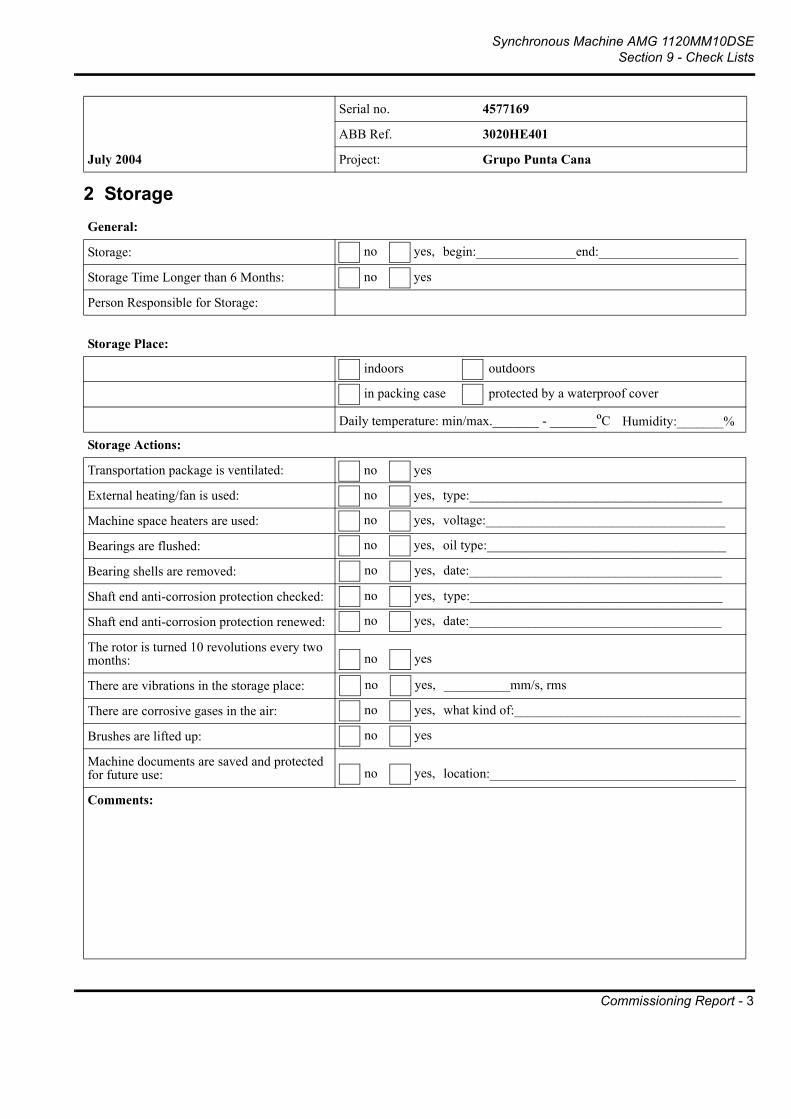
Synchronous Machine AMG 1120MM10DSESection 9 - Check Lists
Commissioning Report - 3
Serial no. 4577169
ABB Ref. 3020HE401
July 2004 Project: Grupo Punta Cana
2 StorageGeneral:
Storage:
Storage Time Longer than 6 Months:
Person Responsible for Storage:
Storage Place:
Storage Actions:
Transportation package is ventilated:
External heating/fan is used:
Machine space heaters are used:
Bearings are flushed:
Bearing shells are removed:
Shaft end anti-corrosion protection checked:
Shaft end anti-corrosion protection renewed:
The rotor is turned 10 revolutions every two months:
There are vibrations in the storage place:
There are corrosive gases in the air:
Brushes are lifted up:
Machine documents are saved and protected for future use:
Comments:
no yes, begin:_______________end:_____________________
no yes
in packing case protected by a waterproof cover
Daily temperature: min/max._______ - _______ºC Humidity:_______%
indoors outdoors
no yes
no yes, type:______________________________________
no yes, voltage:____________________________________
no yes, oil type:____________________________________
no yes, type:______________________________________
no yes
no yes
no yes, location:_____________________________________
no yes, __________mm/s, rms
no yes, what kind of:__________________________________
no yes, date:______________________________________
no yes, date:______________________________________

Synchronous Machine AMG 1120MM10DSESection 9 - Check Lists
Commissioning Report - 4
Serial no. 4577169
ABB Ref. 3020HE401
July 2004 Project: Grupo Punta Cana
3 Mechanical InstallationFoundation is checked according to machine drawing:
Possible foundation anchor bolts or sole plates are mounted according to instructions:
Air gap is measured:For pedestal bearings, mark values 1-4, and for flanged bearings, values A-D
1 ____________ A ____________
2 ____________ B ____________
3 ____________ C ____________
4 ____________ D ____________
For alignment of the coupling, use either values 1-4 or values A-D
1 ____________
2 ____________
3 ____________
4 ____________
A ____________
B ____________
C ____________
D ____________
Axial position of the rotor: ET #1:__________mm, ET #2:__________mm
Axial distance between shaft ends: __________mmRotor support distance:
Crankshaft deflection is checked:
Tapered guide pins are used to lock the position of the machine after alignment:
Foundations bolts are tightened with torque wrench:
Bolt lubrication:
Cooling water:
Cooling element piping:
Transport locking device is removed:
Rotor rotates without noise or scraping:
no yes, bolt size:_____________torque:_______________Nm
no yes, drawing number:_____________________________
no yes
no yes
no yes
dry
no yes
topRadial alignment of coupling
D-endtop
topAngular alignment of coupling
N-endtop
Exciter N-endtop
no yes
______mm ______mm
flexible rigid
yes, amount:no m3/s
oil, MoS2
1
2
3
4
A
BC
D1
A
2
B3
C
4
D1
2
3
4
A
BC
D
1
2
3
4
A
BC
D1
2
3
4
A
BC
D

Synchronous Machine AMG 1120MM10DSESection 9 - Check Lists
Commissioning Report - 5
Serial no. 4577169
ABB Ref. 3020HE401
July 2004 Project: Grupo Punta Cana
4 Lubrication check
4.1 Self lubrication
4.2 Forced lubrication
4.3 Grease lubricated bearings:
Bearing oil: Manufacturer:__________________ Type:_________________________
The oil quality is the same as recommended :
Bearing oil is filled up to the indicated level:Please mark the level in the sight glass circle on the right
Lubrication rings rotate freely:
Bearing oil: Manufacturer:__________________ Type:_________________________
The oil quality is the same as recommended:
Lubrication rings rotate freely:
Force lubrication oil pressure: ___________kPa
Oil flow: ___________liters/min
Rotation of the pumps checked:
Jack-up pumps checked:
Oil filters checked:
Grease: Manufacturer:__________________ Type:_________________________
The grease quality is the same as recommended on the lubrication plate:
The first greasing has been done: Date:_______________ Quantity:________g
Comments:
no yes
Sight Glass
no yes
no yes
no yes
no yes,
no yes
no yes
alarm setting:_____kPa, relief valve setting:______kPa
no yes

Synchronous Machine AMG 1120MM10DSESection 9 - Check Lists
Commissioning Report - 6
Serial no. 4577169
ABB Ref. 3020HE401
July 2004 Project: Grupo Punta Cana
5 Electrical installation
5.1 Insulation Resistance Test
5.2 Accessories resistance test
Network variation:
Space heater operation:
Space heater for slip ring unit:
Stator winding (1 min.): __________MΩ, tested by________ kV, winding temperature:______ºCStator winding (15 / 60 s. or 1 / 10 min.): PI =__________, tested by________ kV, winding temperature:______ºCRotor winding (1 min., 500 VDC): __________MΩ, tested by________ kV, winding temperature:______ºCExciter stator (1 min., 500 VDC): __________MΩ, tested by________ kV, winding temperature:______ºCSpace heater: __________MΩ (500 VDC)
Temperature detectors: __________MΩ (100 VDC)
N-end bearing insulation: __________MΩ (100 VDC)
Stator 1 PT 100:Stator 2 PT 100:Stator 3 PT 100:Stator 4 PT 100:Stator 5 PT 100:Stator 6 PT 100:
__________Ω__________Ω__________Ω__________Ω__________Ω__________Ω
Bearing PT 100 D-end:Bearing PT 100 N-end:
__________Ω__________Ω
Air temperature 1 PT 100:Air temperature 2 PT 100:
__________Ω__________Ω
Space heater: __________Ω
no yes, voltage:______-______V, frequency:_____-______Hz
no manual automatic, controlled by:_________________
no yes, voltage:_____________V, power:_______________W

Synchronous Machine AMG 1120MM10DSESection 9 - Check Lists
Commissioning Report - 7
Serial no. 4577169
ABB Ref. 3020HE401
July 2004 Project: Grupo Punta Cana
6 Machine protection settingsOvercurrent tripping: _______________A _________________ s
Instant overcurrent tripping: _______________A _________________ s
Overvoltage setting:
Earth fault setting:
Reverse power setting:
Differential protection setting:
Vibration monitoring:
Temperature monitoring:
- in stator winding- in bearing- in ______________________________
Other protection units:
no yes, setting:
no yes, setting:
no yes, setting:
no yes, setting:
no yes, alarm:__________mm/s, trip:______________mm/s
no yes, type:
no yes, alarm:__________ºC, trip:______________ºCno yes, alarm:__________ºC, trip:______________ºC
no yes, alarm:__________ºC, trip:______________ºC

Synchronous Machine AMG 1120MM10DSESection 9 - Check Lists
Commissioning Report - 8
Serial no. 4577169
ABB Ref. 3020HE401
July 2004 Project: Grupo Punta Cana
7 Test Run
7.1 First start (a few seconds only)Note: Check that possible force lubrication is on!
7.2 Second start (uncoupled, if possible)Note: Check that possible force lubrication is on!
Checking schedule and information
Direction of rotation (viewed from D-end):
Are there abnormal noises?
Are there abnormal noises?
Does the machine vibrate abnormally?
Bearing vibration level measured: D-end:__________ mm/s, rms; N-end:_________ mm/s, rms
Running:
Time Bearing temperature Bearing vibration levels Stator Stator winding temperature
D-end N-end D-endmm/s
N-endmm/s
Current Power Factor
Excit. Current
U V W
h:min ºC ºC rms rms A cos φ A ºC ºC ºC0:00
0:05
0:10
0:15
0:20
Comments:
Observations:
CW CCW
no yes, from:
machine run OK operation stops, why:
no yes, from:
no yes, where/how:

Synchronous Machine AMG 1120MM10DSESection 9 - Check Lists
Commissioning Report - 9
Serial no. 4577169
ABB Ref. 3020HE401
July 2004 Project: Grupo Punta Cana
8 Test run (with load)Checking schedule and information
9 Machine approval
Time Load Bearing temp. Bearing vibration levels Stator Stator winding temperature
D-end N-end D-endmm/s
N-endmm/s
Current Power Factor
Excit. Current
U V W
h:min % ºC ºC rms rms A cos φ A ºC ºC ºC0:00
Vibration spectrum attached:
Acceleration time: __________ s.
Cooling air temperature: Inlet: __________ ºC Outlet:__________ ºCCooling water temperature: Inlet: __________ ºC Outlet:__________ ºCComments:
Machine approved for use Date:
Commissioning done by:
Approved by:
no yes

Synchronous Machine AMG 1120MM10DSESection 9 - Check Lists
Commissioning Report - 10
Serial no. 4577169
ABB Ref. 3020HE401
July 2004 Project: Grupo Punta Cana
Fax Cover SheetDate:
To: ABB OySynchronous MachinesTelefax: +358 (0) 10 22 22675
From:
Fax number:
Phone number:
Email:
Number of Pages: 1 + 9 + _________
Message:
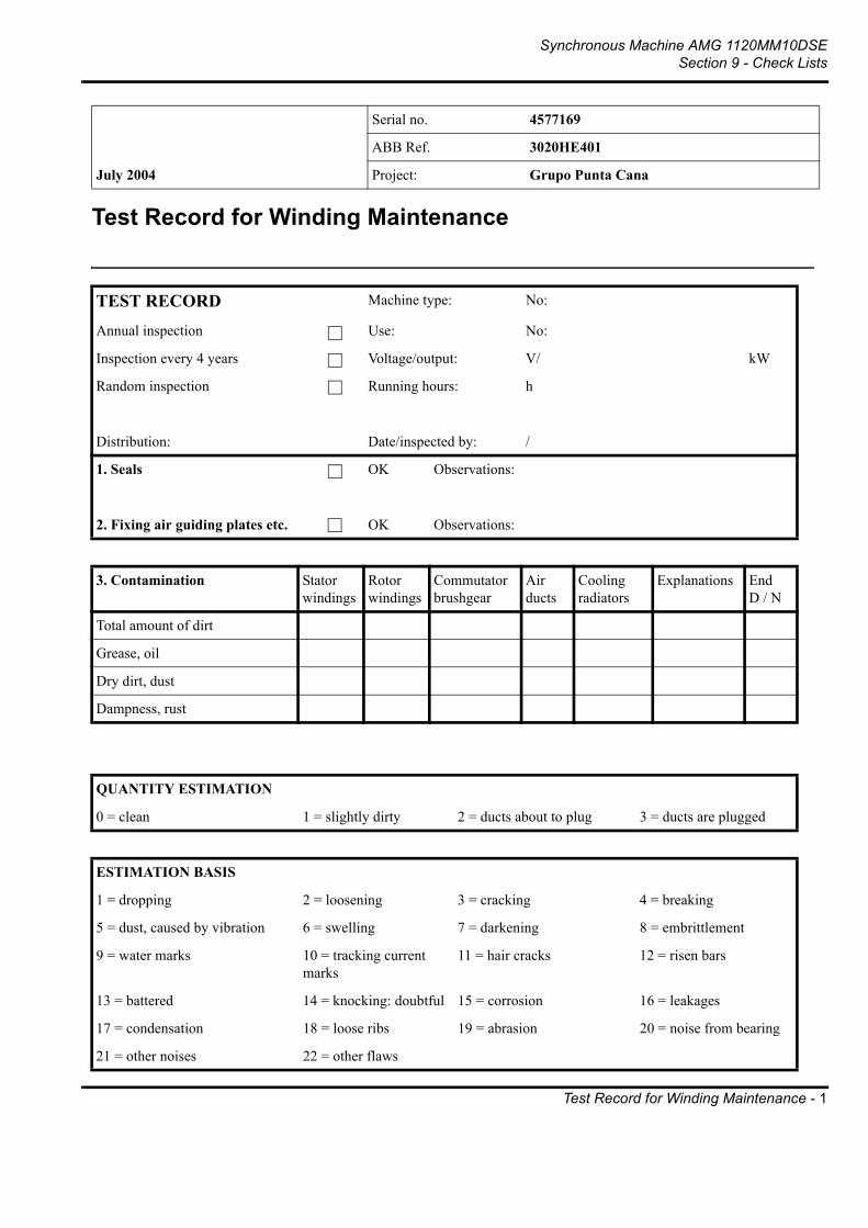
Synchronous Machine AMG 1120MM10DSESection 9 - Check Lists
Test Record for Winding Maintenance - 1
Serial no. 4577169
ABB Ref. 3020HE401
July 2004 Project: Grupo Punta Cana
Test Record for Winding Maintenance
TEST RECORD Machine type: No:
Annual inspection Use: No:
Inspection every 4 years Voltage/output: V/ kW
Random inspection Running hours: h
Distribution: Date/inspected by: /
1. Seals OK Observations:
2. Fixing air guiding plates etc. OK Observations:
3. Contamination Stator windings
Rotor windings
Commutator brushgear
Air ducts
Cooling radiators
Explanations EndD / N
Total amount of dirt
Grease, oil
Dry dirt, dust
Dampness, rust
QUANTITY ESTIMATION
0 = clean 1 = slightly dirty 2 = ducts about to plug 3 = ducts are plugged
ESTIMATION BASIS
1 = dropping 2 = loosening 3 = cracking 4 = breaking
5 = dust, caused by vibration 6 = swelling 7 = darkening 8 = embrittlement
9 = water marks 10 = tracking current marks
11 = hair cracks 12 = risen bars
13 = battered 14 = knocking: doubtful 15 = corrosion 16 = leakages
17 = condensation 18 = loose ribs 19 = abrasion 20 = noise from bearing
21 = other noises 22 = other flaws

Synchronous Machine AMG 1120MM10DSESection 9 - Check Lists
Test Record for Winding Maintenance - 2
Serial no. 4577169
ABB Ref. 3020HE401
July 2004 Project: Grupo Punta Cana
4. WINDINGS OK Observations D / N
4.1 AC Stator
Support
Coils
Connecting cables
Core laminations
4.2 Synchronous rotor
Coils, insulations, support
Pole, poleshoe, bolts
Connection ring
4.3 Asynchronous rotor
Ends of squir. cage windings
Key of squir. cage ring
Core laminations
4.4 DC stator
Windings, insulations
Fixing the windings
Connecting leads
4.5 DC rotor
Coils
Bandage
Core laminations
5. FAN
6. COOLING SYSTEM
Visible radiator parts
Inner radiator parts
Flow-switch

Synchronous Machine AMG 1120MM10DSESection 9 - Check Lists
Test Record for Winding Maintenance - 3
Serial no. 4577169
ABB Ref. 3020HE401
July 2004 Project: Grupo Punta Cana
7. ELECTRICAL CONNECTIONS
Main connection
Control gear
8. ELECTRICAL TESTS
Insulation resistance to earth R15= MΩ, R60= MΩ
Winding temperature:
Voltage test 1 min. Test voltage:
Operation test of protection Voltage kV, DC voltage AC voltage

Synchronous Machine AMG 1120MM10DSESection 9 - Check Lists
Pt-100 Failure Inspection Protocol - 1
Serial no. 4577169
ABB Ref. 3020HE401
July 2004 Project: Grupo Punta Cana
Pt-100 Failure Inspection Protocol
This check list helps to provide ABB with sufficient data to determine the cause of Pt-100 sensor damages. Please mark N/A on points not valid in your case.
1 General
2 Operational information
Customer:
Azipod
Type of machine:
Serial number:
Project name or order number:
Start up date (dd/mm/yyyy):
Application:
Operating hours before failure:
Output at the time of failure:
Normal operating load:
Normal operating temperatures:
Ambient temperature:
Minimum and maximum ambient temperatures:
Service done before damage:
Disturbances before damage (e.g. high vibration):
Generator Motor
h
Power: kW Speed: rpm
Current: A Temperature: °C
Power: kW Current: A
Temperature: °C
D-end: °C
N-end: °C
Stator: °C
Rotor: °C
°C
°C °C

Synchronous Machine AMG 1120MM10DSESection 9 - Check Lists
Pt-100 Failure Inspection Protocol - 2
Serial no. 4577169
ABB Ref. 3020HE401
July 2004 Project: Grupo Punta Cana
3 Additional information
4 Current situation
5 Material to be provided to ABB
Where the damaged sensors are and how many sensors are damaged:
Stator winding
When the damage was discovered:
Were several sensors damaged at the same time:
Were there other damages in system at the same time:
How the damage was discovered: In monitoring system
Where were the sensors checked after damage: In junction box
Manufacturer of damaged sensor:
Resistance between 3-wire Minco sensor wires, if other sensor, update colors:
Where is the machine at the moment:
What has been done so far to the machine due to this damage:
Additional comments:
Photographs of machine:
Temperature trend curves:
Other material:
red-blue
Hot air Cool air
If otherwise, how:
If not, where:
Thermo-EstMinco Some other, who:
Bearing
red-white blue-white

Synchronous Machine AMG 1120MM10DSESection 9 - Check Lists
Pt-100 Failure Inspection Protocol - 3
Serial no. 4577169
ABB Ref. 3020HE401
July 2004 Project: Grupo Punta Cana
6 Contact information
Thank you very much for your co-operation!
Date (dd/mm/yyyy):
Place:
Signature:
Name, title:
Company:
Phone:
Fax:
E-mail:

Synchronous Machine AMG 1120MM10DSESection 9 - Check Lists
RENK Check List for Horizontal Bearings - 1
Oil Leakage’s at RENK Slide Bearings?A Check List for Horizontal Bearings
In case of oil leakage's in the bearing area, this check list may help you to find fail reasons or to set up a detailed fail report to our service department. Your answers of necessary questions will help us to find reasons and solutions to the problems.
General informations
1.1 Machine Scheme (designation convention and description)
Type of machine: ___________________
Type of machine: ___________________coupled to DE
2 Seals 1 1 Seals 2 (Seal position e.g. DE_2 or NDE_1)
(in case of leaking seals mark the desired check-box)
1.2 To read from nameplate of bearing:
Bearing Type: (e.g. EFZLA 14-140) DE _____________ NDE _____________
RENK Ref. N°: (e.g. 446 123) DE _____________ NDE _____________
Oil viscosity: (e.g. ISO VG 46) DE _____________ NDE _____________
1.3.Type of oil applied: unknown Manufacturer: _________________
Denomination: _________________
1.4 Informations on operational conditions:
nominal speed: ________ RPM overspeed: _____________ RPM
DE NDEMACHINE
Bearg.Bearg.

Synchronous Machine AMG 1120MM10DSESection 9 - Check Lists
RENK Check List for Horizontal Bearings - 2
1.5 Types of mounted seals:
DE_1: Typ ___ DE_2: Typ ___ NDE_1: Typ ___ NDE_2: Typ ___(ad on's to basic types)
Typ “10” Typ “20” Typ + 1 Typ + 2Floating Labyrinth S. Rigid Labyrinth S. Dust Flinger Bolt-on Baffle
(Typ numbers for basic seals with "ad on": Typ 11 or 12 respective Typ 21 or 22)
2.1 Intensity of oil leakage's:
less than 2 drops per dayless than 10 drops per daymore than 10 drops per day
2.2 Localisation of leakage's:
Seals (please answer questions 3 - 25, 30)screw connections / pipes (please answer questions 26 - 30)split line of bearing housings (please answer questions 3 - 8, 14, 22, 29, 30)
3. Is the oil level correct? yes no
4. Foams the oil heavily? yes no
5. Is the foam visible yes noin the sight glass?
6. Normal bearing shell temperature?
unknown ____ °C
7. Oil sump temperature?
unknown ____ °C
8. Machine and bearings horizontally aligned?
yes no, inclination (axline): ____°
sea! axline: ____° across: ____°

Synchronous Machine AMG 1120MM10DSESection 9 - Check Lists
RENK Check List for Horizontal Bearings - 3
Shaft Seals - Details
9. Where do the leakage's at seal appear?
between seal and shaftbetween seal and housingdifficult to recognise
10. Seals gap to shaft - can you measure the gaps at positions 12, 3, 6 and 9 o'clock positions with view towards bearing; the seal should not be disassembled before?Please note also seals machine-position.
If not possible, can you measure alternatively the shaft diameter at seals seat?
no yes: please note below
⎯|⎯ ⎯|⎯ (mm)
⎯|⎯ ⎯|⎯ (mm)
11. Did you realise gaps in the split line of seals (by means of a feeler / plate gauge)?(In case of Floating Labyrinth Seal: fit the seal with its garter spring - but without the carrier - onto the shaft)
no yes: note gap's below
<⎯|⎯> <⎯|⎯> (mm)
12. Is there any damaged baffle (at seals)?
yes no
13. Are the oil drain holes of seals in the lower half and they are open to bearing housing?
yes no14. Has been applied "Curil T" (or other non-hardening sealant) on all joints, split lines of housings and seals as well as between housing and seals prior to assembly?
yes no
15. If Floating Lab. Seal is used, has been applied "Curil T" to the flanks of this seals?
yes no
16. Are there deflectors at the shaft - between bearing shell and seal area?
yes no

Synchronous Machine AMG 1120MM10DSESection 9 - Check Lists
RENK Check List for Horizontal Bearings - 4
Differences in Air Pressure / Air Streams
17. Are there components outside the bearing, close to the seal area, which might cause a draught (fans, cooling discs, couplings flywheels, belt drives)?
yes no
Distance inbetween: ______ mm
18. Is there a difference in air pressure from inside bearing to outside (low or high pressure differences of more than 30 Pa respective 3 mm WC are of interest; please sign low pressure with minus)?
no could not be measured
DE: ____ Pa NDE: ____ Pa
19. Are there low or high pressure in front of seals (at machine side of flanged bearings - housings EF or EM - you can measure in the channels respective connections for air pressure compensation)?
no could not be measured
DE_1: ____ Pa DE_2: ____ Pa
NDE_1: ____ Pa NDE_2: ____ Pa
20. If there is a breather mounted at the bearing house, is this device (filter) dry and clean?
no device device mounted yes no. oil-wet --> or: __
21. In case of pressure differences, did you have any idea of its origin (note it please)?
External oil supply
If there is only a circulation from oil sump of bearing direct to bearing entry (oil circulation pump at each bearing), please strike out questions 23, 24 and 25.
22. Please note oil throughput + oil pressure + oil temperature at each bearing entry:
unknown
DE: ____ l/min ____ bar ____ °C
NDE: ____ l/min ____ bar ____ °C
23. Inclination of oil return pipe between bearing and oil tank:
< 10 deg. ≥ 10 deg > 15 deg.
24. Nominal diameter of oil return pipe

Synchronous Machine AMG 1120MM10DSESection 9 - Check Lists
RENK Check List for Horizontal Bearings - 5
________ mm
25. If you found high pressure inside bearing, is it possible that this pressure comes along the oil return pipe (from tank; e.g. produced by pressurised air seals at other components in the oil circulation system)?
yes no
Screw connections and Vibrations
26. Which screw connections are leaking?
locking screw with plastic seallocking screw with copper gasketoil sight glassconnection of oil return pipe - with hexagon nut and lead gasket
27. Are the locking screws tightened according to torque's (Nm) given below?
G 1/8: 18 G 1/4: 22 G 3/8: 30G 1/2: 40 G 3/4: 60 G 1 : ..110G 1 1/4: 160 G 1 1/2: 230 G 2 : ..320G 2 1/2: 500
yes no
28. Has the screw connection of the oil return pipe in the bearing house been relieved from the tube weight by appropriate fixing devices?
yes no
29. Are there vibrations at the oil return pipe?
no low strong
30. Did you measure vibrations of the housings and / or of the shaft?
no yes, Veff = _____ mm/s
amplitude Smax = ____ µm

Synchronous Machine AMG 1120MM10DSESection 9 - Check Lists
RENK Check List for Horizontal Bearings - 6
RENK AG, Werk Hannover (Germany)Dept.: HVA (after sales service)Fax: +49.511.8601 - 288e-mail: [email protected]

User’s Manual
Serial no.ABB ref.Project:
ABB
Synchronous MachineAMG 1120MM10DSE
45771693020HE401
July 2004 Grupo Punta Cana
10.AdditionalInformation

ABBABB OySynchronous MachinesP.O. Box 186FIN-00381 HELSINKIFINLANDTelephone + 358 (0)10 22 2000Telefax + 358 (0)10 22 22675