Generation of Short Wavelength Modulation through Compression · Generation of Short Wavelength...
30
Generation of Short Wavelength Modulation through Compression Ji Qiang Lawrence Berkeley National Laboratory ICFA FLS 2010 workshop, SLAC, March 1-5, 2010
Transcript of Generation of Short Wavelength Modulation through Compression · Generation of Short Wavelength...
Generation of Short Wavelength Modulation
through Compression
Ji Qiang
Lawrence Berkeley National Laboratory
ICFA FLS 2010 workshop, SLAC, March 1-5, 2010
Acknowledgements
We would like to thank J. Corlett, B. Fawley, G. Penn, R. Ryne, C. Toth,
M. Venturini, J. Wu, A. Zholents for useful discussions. This work is
supported by the LDRD project at LBNL, supported by the Office of
Science of the U.S. Department of Energy under Contract No.
DE-AC02-05CH11231. We have used computing resources at NERSC.
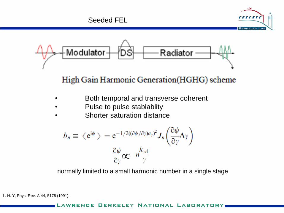
Seeded FEL
• Both temporal and transverse coherent
• Pulse to pulse stablablity
• Shorter saturation distance
L. H. Y, Phys. Rev. A 44, 5178 (1991).
normally limited to a small harmonic number in a single stage
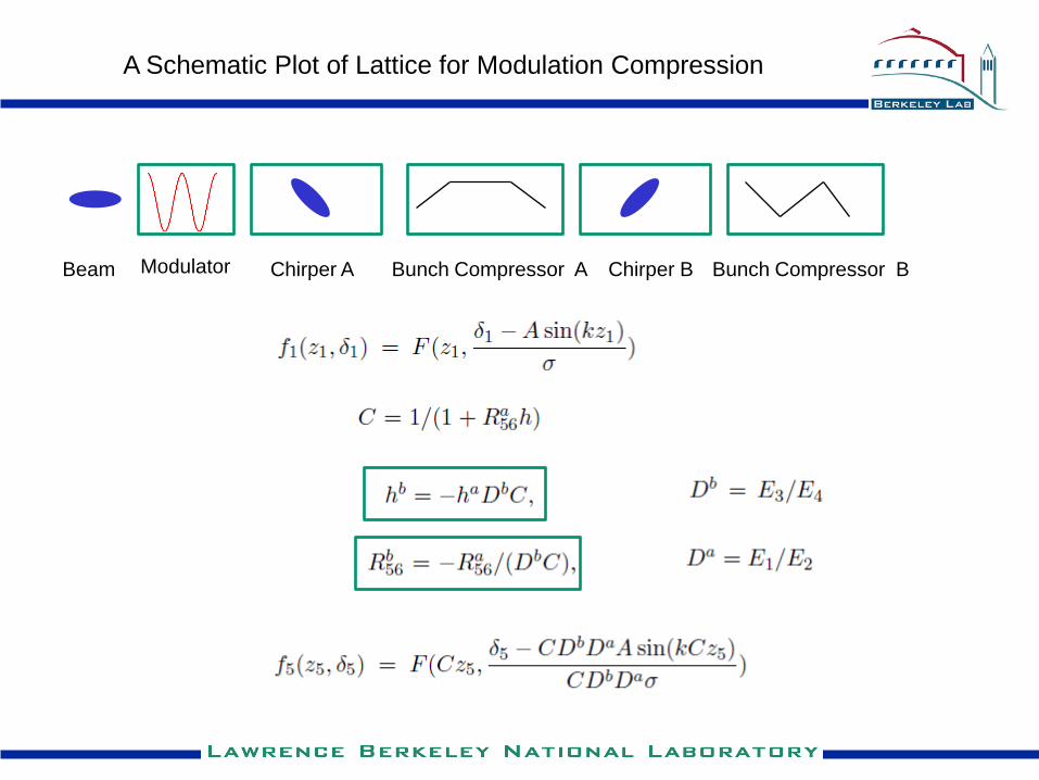
Beam Modulator Bunch Compressor AChirper A Chirper B
A Schematic Plot of Lattice for Modulation Compression
Bunch Compressor B
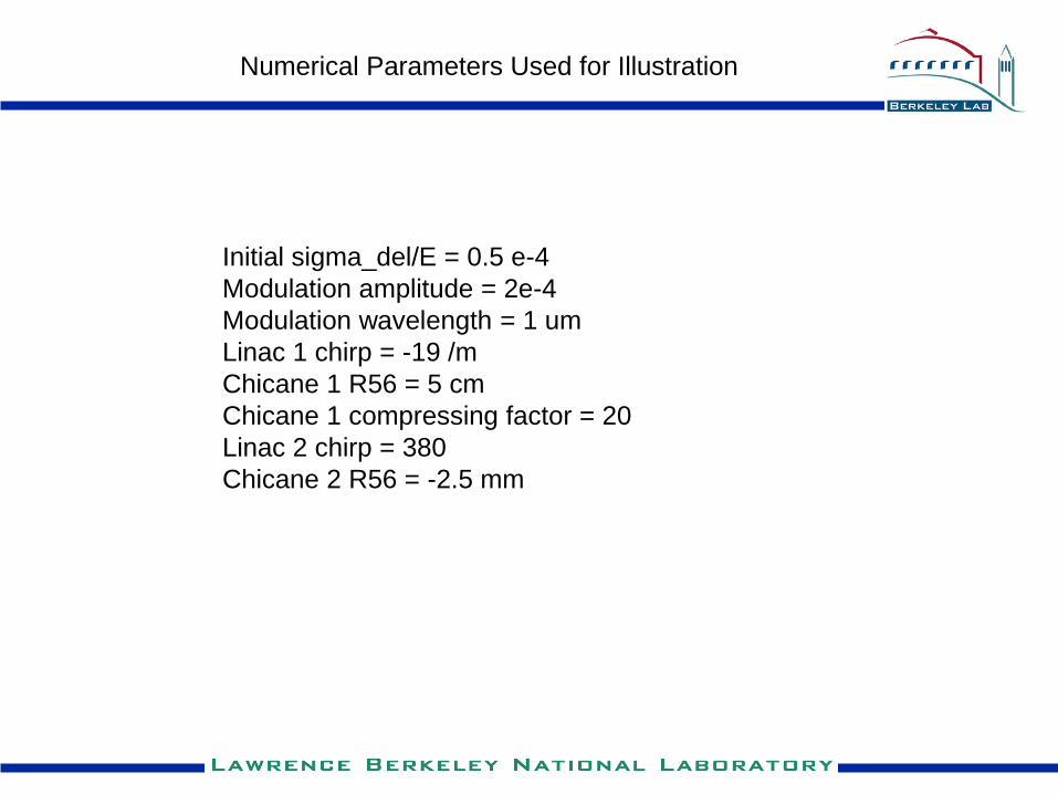
Initial sigma_del/E = 0.5 e-4
Modulation amplitude = 2e-4
Modulation wavelength = 1 um
Linac 1 chirp = -19 /m
Chicane 1 R56 = 5 cm
Chicane 1 compressing factor = 20
Linac 2 chirp = 380
Chicane 2 R56 = -2.5 mm
Numerical Parameters Used for Illustration
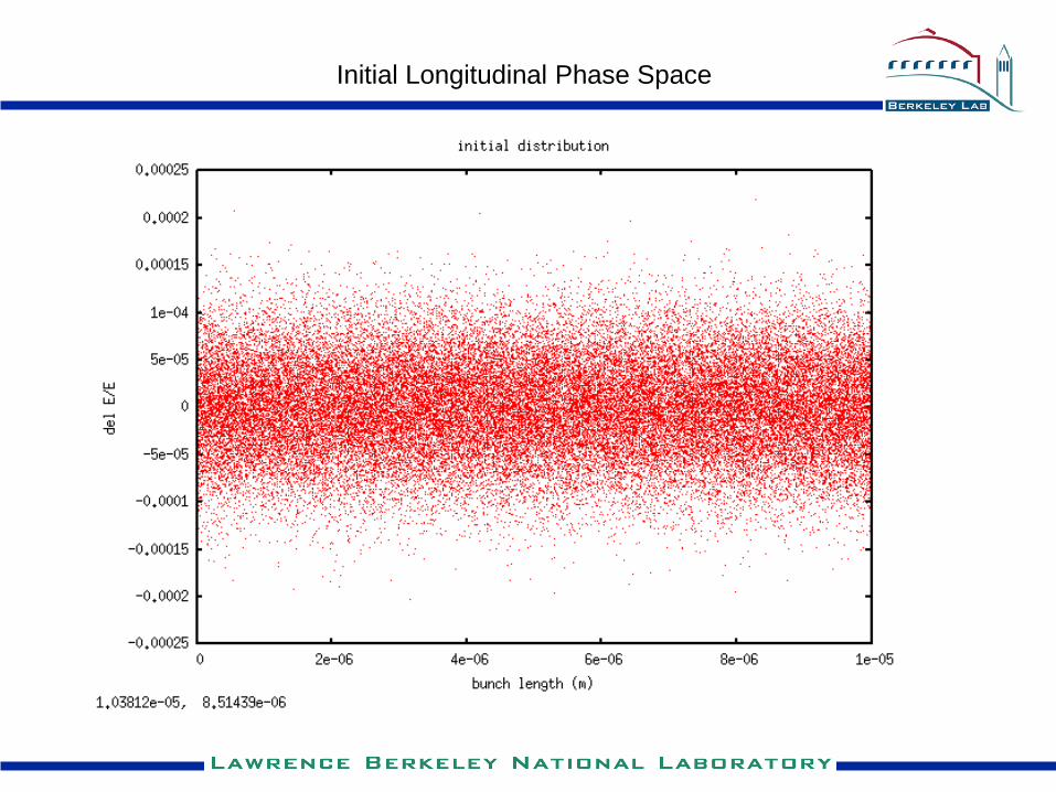
Initial Longitudinal Phase Space
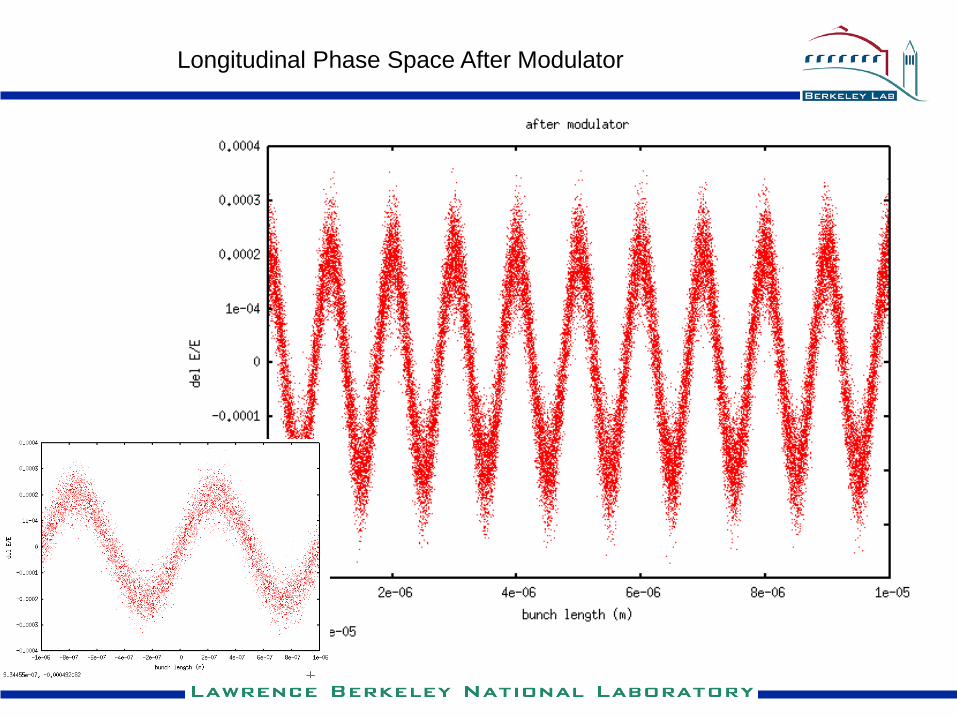
Longitudinal Phase Space After Modulator
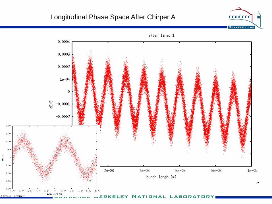
Longitudinal Phase Space After Chirper A
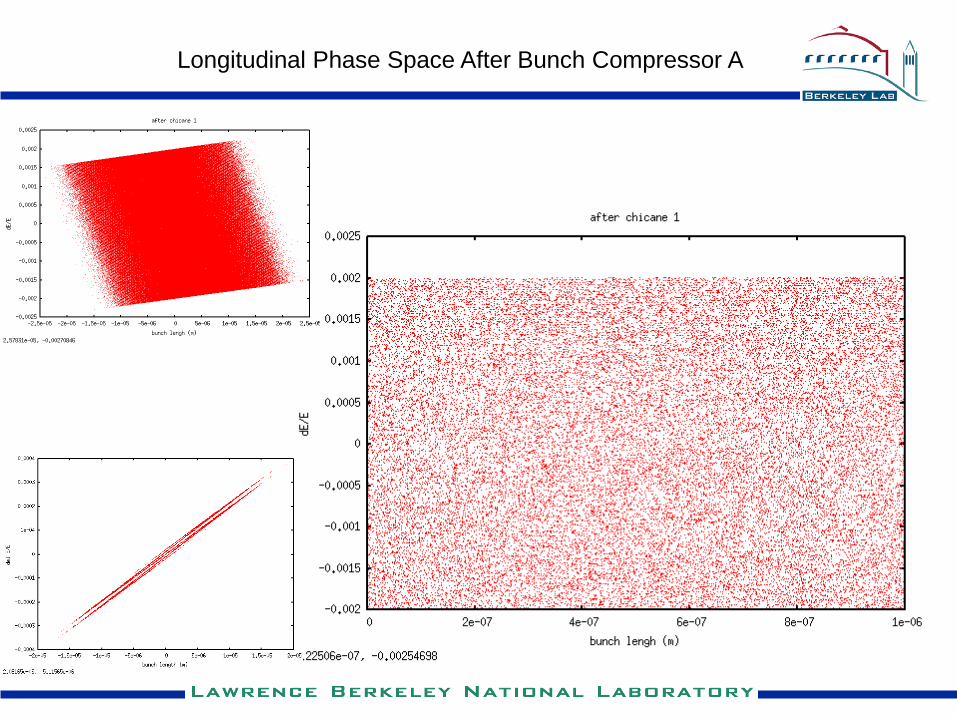
Longitudinal Phase Space After Bunch Compressor A
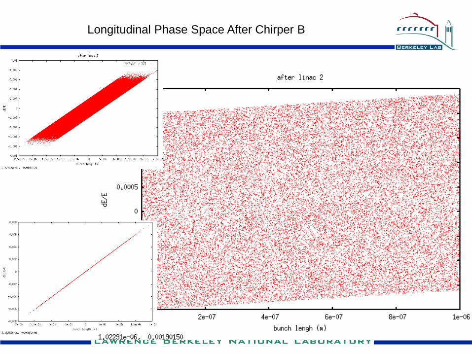
Longitudinal Phase Space After Chirper B
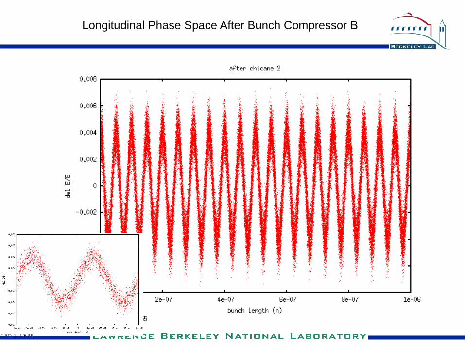
Longitudinal Phase Space After Bunch Compressor B
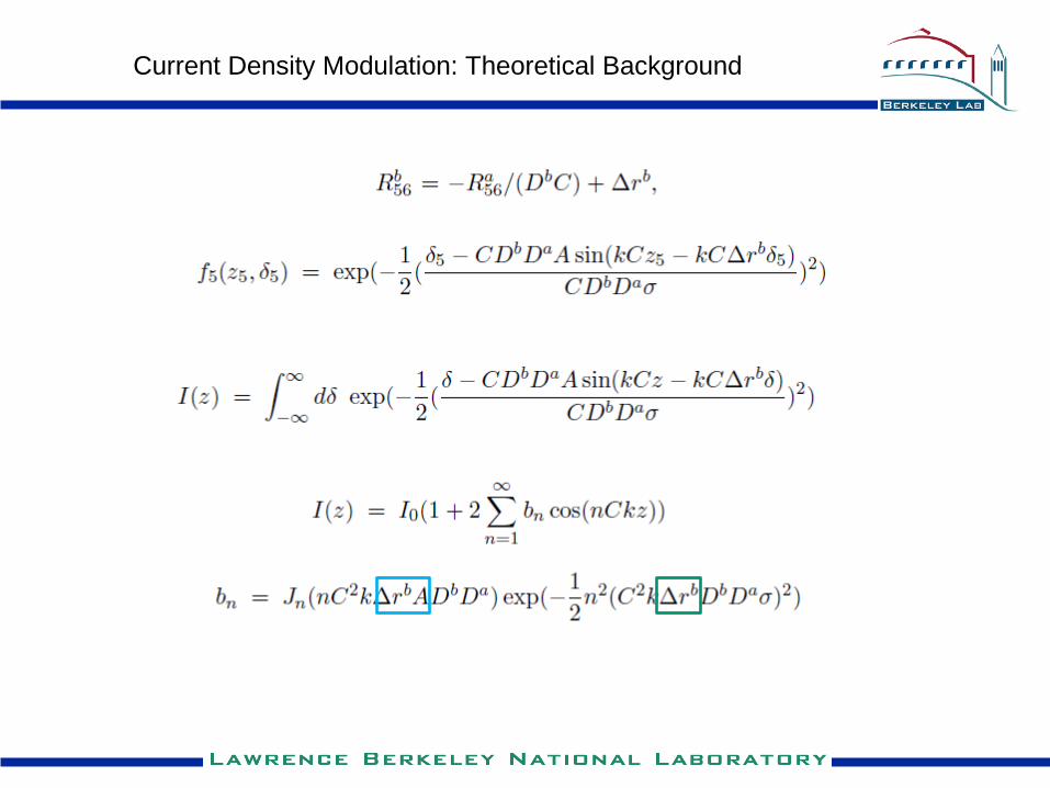
Current Density Modulation: Theoretical Background
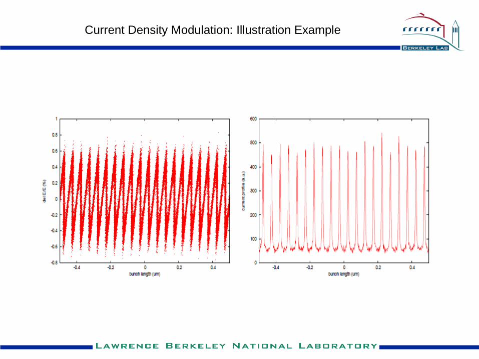
Current Density Modulation: Illustration Example
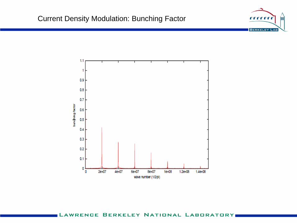
Current Density Modulation: Bunching Factor
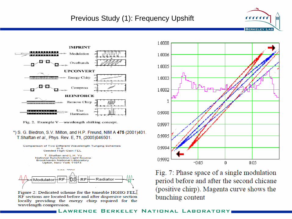
Previous Study (1): Frequency Upshift
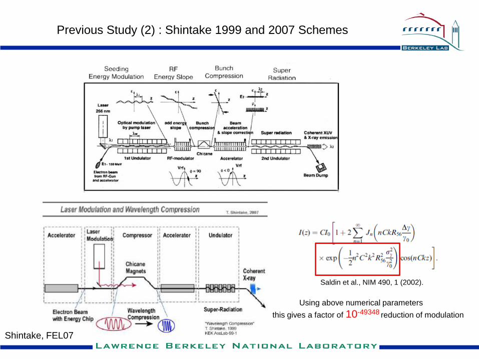
Previous Study (2) : Shintake 1999 and 2007 Schemes
Saldin et al., NIM 490, 1 (2002).
Using above numerical parameters
this gives a factor of 10-49348 reduction of modulation
Shintake, FEL07
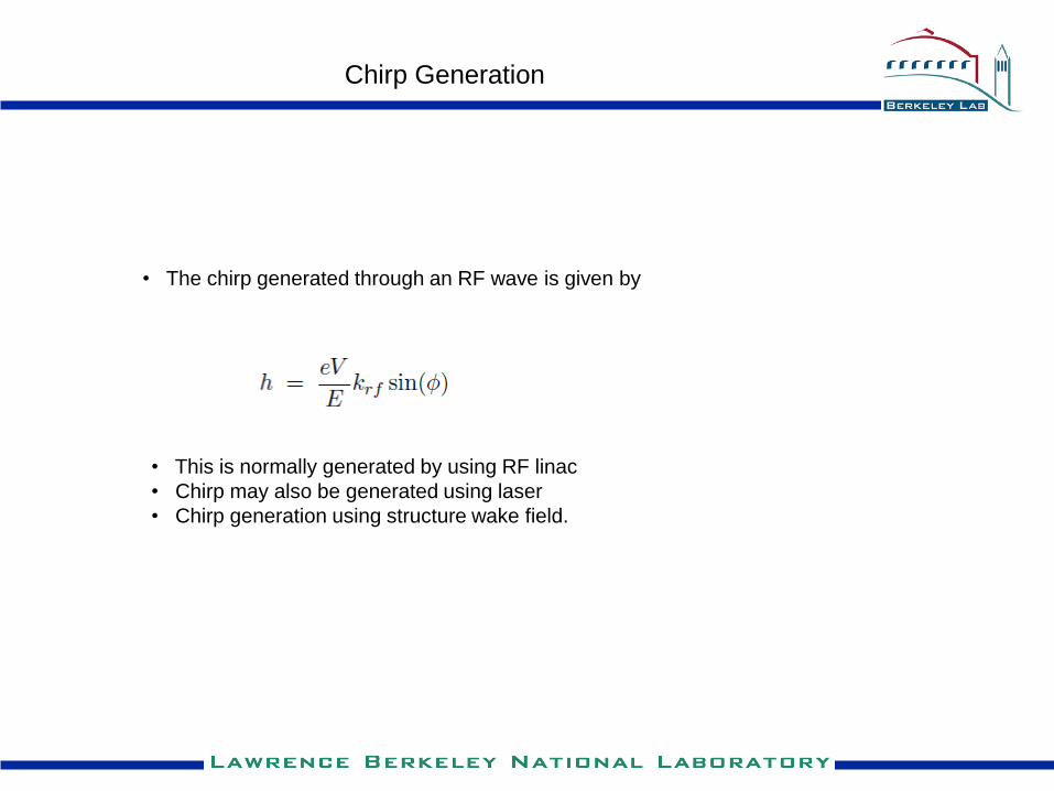
• This is normally generated by using RF linac
• Chirp may also be generated using laser
• Chirp generation using structure wake field.
Chirp Generation
• The chirp generated through an RF wave is given by
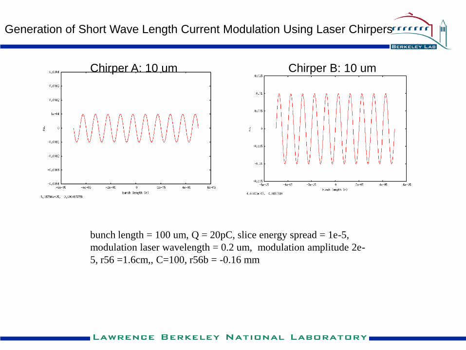
Generation of Short Wave Length Current Modulation Using Laser Chirpers
Chirper A: 10 um Chirper B: 10 um
bunch length = 100 um, Q = 20pC, slice energy spread = 1e-5,
modulation laser wavelength = 0.2 um, modulation amplitude 2e-
5, r56 =1.6cm,, C=100, r56b = -0.16 mm
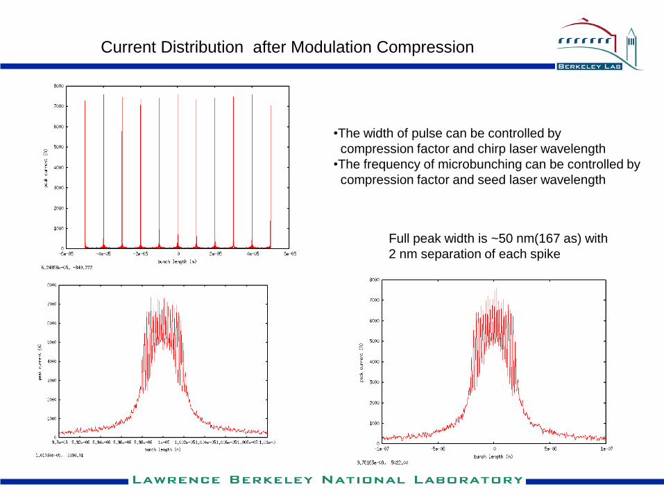
Current Distribution after Modulation Compression
Full peak width is ~50 nm(167 as) with
2 nm separation of each spike
•The width of pulse can be controlled by
compression factor and chirp laser wavelength
•The frequency of microbunching can be controlled by
compression factor and seed laser wavelength
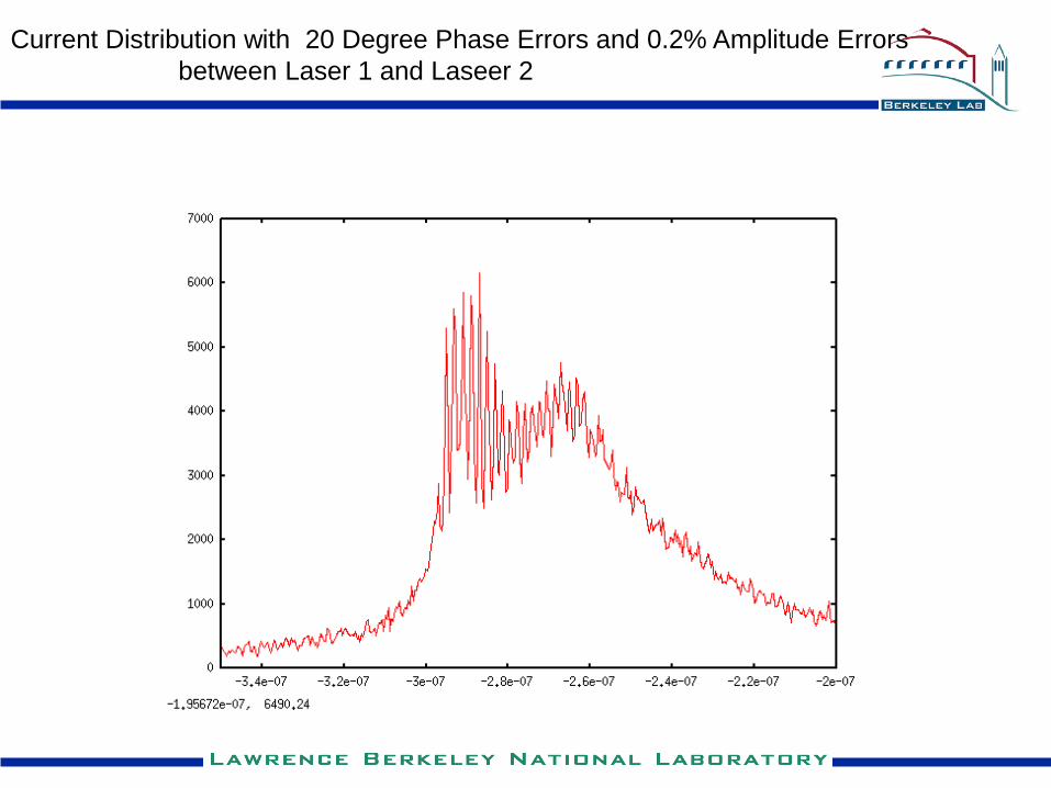
Current Distribution with 20 Degree Phase Errors and 0.2% Amplitude Errors
between Laser 1 and Laseer 2
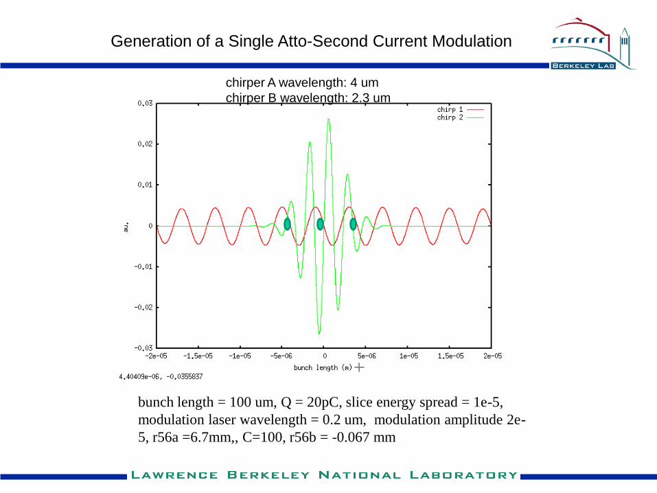
Generation of a Single Atto-Second Current Modulation
bunch length = 100 um, Q = 20pC, slice energy spread = 1e-5,
modulation laser wavelength = 0.2 um, modulation amplitude 2e-
5, r56a =6.7mm,, C=100, r56b = -0.067 mm
chirper A wavelength: 4 um
chirper B wavelength: 2.3 um
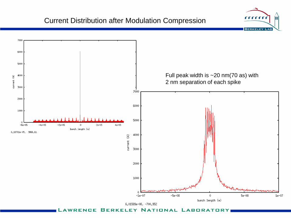
Current Distribution after Modulation Compression
Full peak width is ~20 nm(70 as) with
2 nm separation of each spike
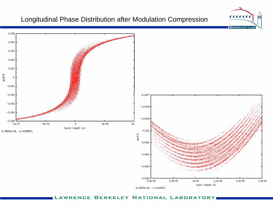
Longitudinal Phase Distribution after Modulation Compression
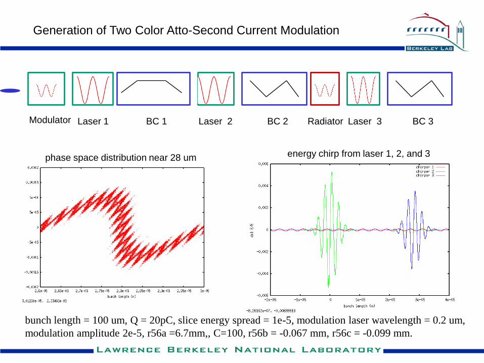
Generation of Two Color Atto-Second Current Modulation
Modulator BC 1Laser 1 Laser 2 BC 2 Laser 3 BC 3
energy chirp from laser 1, 2, and 3phase space distribution near 28 um
Radiator
bunch length = 100 um, Q = 20pC, slice energy spread = 1e-5, modulation laser wavelength = 0.2 um,
modulation amplitude 2e-5, r56a =6.7mm,, C=100, r56b = -0.067 mm, r56c = -0.099 mm.
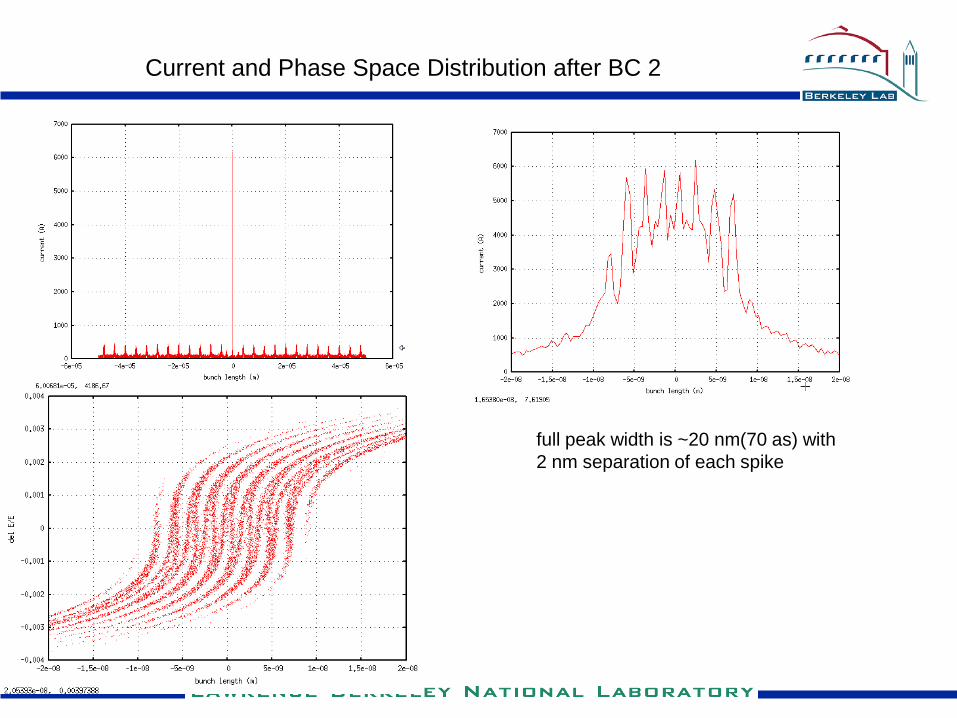
Current and Phase Space Distribution after BC 2
full peak width is ~20 nm(70 as) with
2 nm separation of each spike
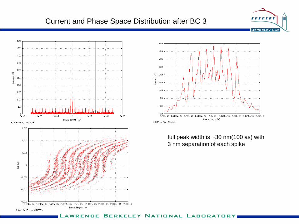
Current and Phase Space Distribution after BC 3
full peak width is ~30 nm(100 as) with
3 nm separation of each spike
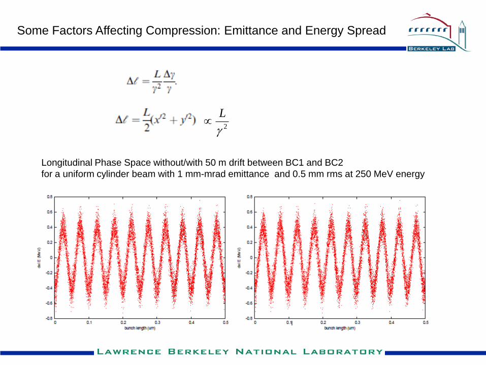
Some Factors Affecting Compression: Emittance and Energy Spread
Longitudinal Phase Space without/with 50 m drift between BC1 and BC2
for a uniform cylinder beam with 1 mm-mrad emittance and 0.5 mm rms at 250 MeV energy
2
L
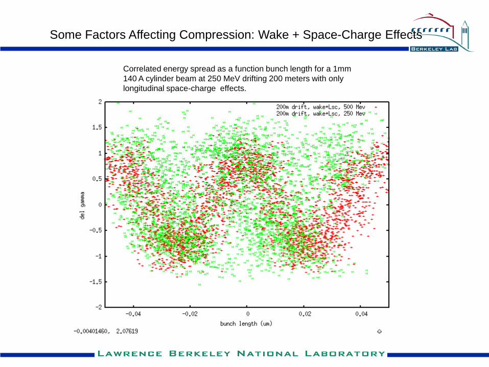
Some Factors Affecting Compression: Wake + Space-Charge Effects
Correlated energy spread as a function bunch length for a 1mm
140 A cylinder beam at 250 MeV drifting 200 meters with only
longitudinal space-charge effects.
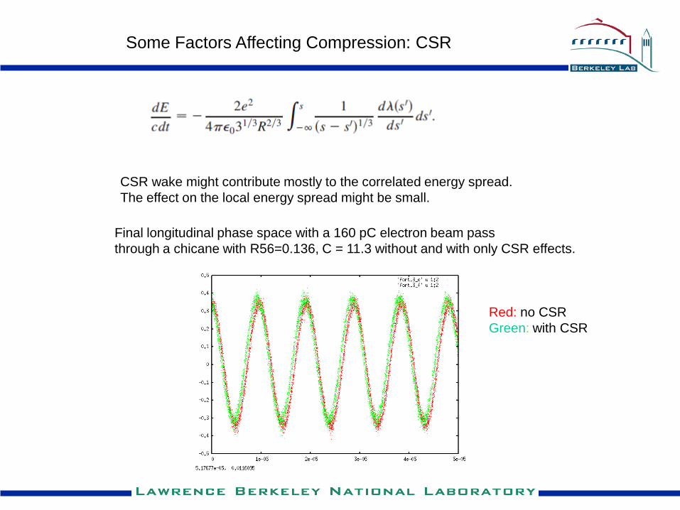
Some Factors Affecting Compression: CSR
Final longitudinal phase space with a 160 pC electron beam pass
through a chicane with R56=0.136, C = 11.3 without and with only CSR effects.
CSR wake might contribute mostly to the correlated energy spread.
The effect on the local energy spread might be small.
Red: no CSR
Green: with CSR
To maximize the advantage of MCHG:
• shorter distance between BC1 and BC 2
• higher energy
• higher RF frequency for chirping or unchirping the beam
• smaller R56b
• maintain accelerator machine linearity
• minimize jitter effects
Summary Discussions
Advantages of MCHG:
• tunable short wave length current modulation for FEL radiation
• large bunching factor for short wave length modulation
• potential low global current, high local peak current operation with laser chirpers


![OPEN ACCESS sensors - Princeton University · Sensors 2015, 15 25994 (ii) laser wavelength modulation (DC-FRS) [17,18,20], where the former eliminates optical etalon effects through](https://static.fdocuments.in/doc/165x107/6118b89ad3a4e17dd868d1ca/open-access-sensors-princeton-university-sensors-2015-15-25994-ii-laser-wavelength.jpg)