Generating multi-GeVelectron bunches using single stage ...
12
Generating multi-GeV electron bunches using single stage laser wakefield acceleration in a 3D nonlinear regime W. Lu, M. Tzoufras, and C. Joshi Department of Electrical Engineering, University of California, Los Angeles, California 90095, USA F. S. Tsung Department of Physics and Astronomy, University of California, Los Angeles, California 90095, USA W. B. Mori Department of Electrical Engineering, University of California, Los Angeles, California 90095, USA, and Department of Physics and Astronomy, University of California, Los Angeles, California 90095, USA J. Vieira, R. A. Fonseca, and L. O. Silva GoLP/Centro de Fisica dos Plasmas, Instituto Superior Te ´chnico, 1049-001 Lisboa, Portugal (Received 19 December 2006; published 5 June 2007) The extraordinary ability of space-charge waves in plasmas to accelerate charged particles at gradients that are orders of magnitude greater than in current accelerators has been well documented. We develop a phenomenological framework for laser wakefield acceleration (LWFA) in the 3D nonlinear regime, in which the plasma electrons are expelled by the radiation pressure of a short pulse laser, leading to nearly complete blowout. Our theory provides a recipe for designing a LWFA for given laser and plasma parameters and estimates the number and the energy of the accelerated electrons whether self-injected or externally injected. These formulas apply for self-guided as well as externally guided pulses (e.g. by plasma channels). We demonstrate our results by presenting a sample particle-in-cell (PIC) simulation of a 30 fs, 200 TW laser interacting with a 0.75 cm long plasma with density 1:5 10 18 cm 3 to produce an ultrashort (10 fs) monoenergetic bunch of self-injected electrons at 1.5 GeV with 0.3 nC of charge. For future higher-energy accelerator applications, we propose a parameter space, which is distinct from that described by Gordienko and Pukhov [Phys. Plasmas 12, 043109 (2005)] in that it involves lower plasma densities and wider spot sizes while keeping the intensity relatively constant. We find that this helps increase the output electron beam energy while keeping the efficiency high. DOI: 10.1103/PhysRevSTAB.10.061301 PACS numbers: 52.38.Kd, 52.35.Mw, 52.65.Rr I. INTRODUCTION In plasma based acceleration, a laser or particle beam creates a plasma wave wakefield with a phase velocity close to the speed of light [1,2]. The acceleration gradients in these wakefields can easily exceed 10 GeV=m which is nearly 3 orders of magnitude larger than that achieved in conventional rf technology. A particle injected in such a wave with sufficient initial energy can interact with the longitudinal component of the electric field for a long enough time, that its energy gain is significant. An intense laser pulse or electron beam can expel the plasma electrons outward to create a bare ion column [3 – 5], which has ideal accelerating and focusing properties for electron beams [4,5]. A recent important development in this field has been the observations in simulations that these highly nonlinear 3D wakefield structures remain stable [6 – 9]. In the laser-driven cases, the simulations showed that self-injected quasimonoenergetic beams of electrons with energies on the order of 100 MeV can be formed [6,7]. In experiments where parameters were chosen such that complete electron expulsion was ex- pected, monoenergetic electron beams were observed [10 –15]. In simulations of these experiments it was found that the energetic electron generation mechanism involves an interplay of complex phenomena: namely, the evolution of the laser, the self-trapping of electrons, and their influ- ence on the wake [16]. The experimental observation of these structures may soon be possible using new diagnostic techniques [17]. In this article, we describe how to extend the results from the recent experiments towards a more stable regime conducive to making an accelerator. We will show that by using near term lasers in the 0:1 to 3 PW range it will be possible to generate 1–13 GeV monoenergetic electron beams with nC of charge in a single stage without the need for external guiding. Using external guiding energies up to 120 GeV can be achieved in a single stage for a 3 PW laser. Unlike in the recent experiments, this regime is characterized by lasers whose intensity and spot size are matched and by relatively low plasma densities. The matched laser profile (both transverse and longitudinal) evolves little during the acceleration distance which greatly exceeds the Rayleigh length. We are motivated to determine a path towards making a compact electron accelerator based on the laser wakefield PHYSICAL REVIEW SPECIAL TOPICS - ACCELERATORS AND BEAMS 10, 061301 (2007) 1098-4402= 07=10(6)=061301(12) 061301-1 © 2007 The American Physical Society
Transcript of Generating multi-GeVelectron bunches using single stage ...

Generating multi-GeV electron bunches using single stage laser wakefield accelerationin a 3D nonlinear regime
W. Lu, M. Tzoufras, and C. JoshiDepartment of Electrical Engineering, University of California, Los Angeles, California 90095, USA
F. S. TsungDepartment of Physics and Astronomy, University of California, Los Angeles, California 90095, USA
W. B. MoriDepartment of Electrical Engineering, University of California, Los Angeles, California 90095, USA,
and Department of Physics and Astronomy, University of California, Los Angeles, California 90095, USA
J. Vieira, R. A. Fonseca, and L. O. SilvaGoLP/Centro de Fisica dos Plasmas, Instituto Superior Technico, 1049-001 Lisboa, Portugal
(Received 19 December 2006; published 5 June 2007)
The extraordinary ability of space-charge waves in plasmas to accelerate charged particles at gradientsthat are orders of magnitude greater than in current accelerators has been well documented. We develop aphenomenological framework for laser wakefield acceleration (LWFA) in the 3D nonlinear regime, inwhich the plasma electrons are expelled by the radiation pressure of a short pulse laser, leading to nearlycomplete blowout. Our theory provides a recipe for designing a LWFA for given laser and plasmaparameters and estimates the number and the energy of the accelerated electrons whether self-injected orexternally injected. These formulas apply for self-guided as well as externally guided pulses (e.g. byplasma channels). We demonstrate our results by presenting a sample particle-in-cell (PIC) simulation of a30 fs, 200 TW laser interacting with a 0.75 cm long plasma with density 1:5� 1018 cm�3 to produce anultrashort (10 fs) monoenergetic bunch of self-injected electrons at 1.5 GeV with 0.3 nC of charge. Forfuture higher-energy accelerator applications, we propose a parameter space, which is distinct from thatdescribed by Gordienko and Pukhov [Phys. Plasmas 12, 043109 (2005)] in that it involves lower plasmadensities and wider spot sizes while keeping the intensity relatively constant. We find that this helpsincrease the output electron beam energy while keeping the efficiency high.
DOI: 10.1103/PhysRevSTAB.10.061301 PACS numbers: 52.38.Kd, 52.35.Mw, 52.65.Rr
I. INTRODUCTION
In plasma based acceleration, a laser or particle beamcreates a plasma wave wakefield with a phase velocityclose to the speed of light [1,2]. The acceleration gradientsin these wakefields can easily exceed 10 GeV=m which isnearly 3 orders of magnitude larger than that achieved inconventional rf technology. A particle injected in such awave with sufficient initial energy can interact with thelongitudinal component of the electric field for a longenough time, that its energy gain is significant.
An intense laser pulse or electron beam can expel theplasma electrons outward to create a bare ion column [3–5], which has ideal accelerating and focusing properties forelectron beams [4,5]. A recent important development inthis field has been the observations in simulations thatthese highly nonlinear 3D wakefield structures remainstable [6–9]. In the laser-driven cases, the simulationsshowed that self-injected quasimonoenergetic beams ofelectrons with energies on the order of 100 MeV can beformed [6,7]. In experiments where parameters werechosen such that complete electron expulsion was ex-pected, monoenergetic electron beams were observed
[10–15]. In simulations of these experiments it was foundthat the energetic electron generation mechanism involvesan interplay of complex phenomena: namely, the evolutionof the laser, the self-trapping of electrons, and their influ-ence on the wake [16]. The experimental observation ofthese structures may soon be possible using new diagnostictechniques [17].
In this article, we describe how to extend the resultsfrom the recent experiments towards a more stable regimeconducive to making an accelerator. We will show that byusing near term lasers in the 0:1 to 3 PW range it will bepossible to generate 1–13 GeV monoenergetic electronbeams with nC of charge in a single stage without theneed for external guiding. Using external guiding energiesup to 120 GeV can be achieved in a single stage for a 3 PWlaser. Unlike in the recent experiments, this regime ischaracterized by lasers whose intensity and spot size arematched and by relatively low plasma densities. Thematched laser profile (both transverse and longitudinal)evolves little during the acceleration distance whichgreatly exceeds the Rayleigh length.
We are motivated to determine a path towards making acompact electron accelerator based on the laser wakefield
PHYSICAL REVIEW SPECIAL TOPICS - ACCELERATORS AND BEAMS 10, 061301 (2007)
1098-4402=07=10(6)=061301(12) 061301-1 © 2007 The American Physical Society

acceleration (LWFA) concept for use in high-energy phys-ics or as a light source. Efficiency and beam quality are keyissues one should keep in mind when making such designs.As shown by Katsouleas et al. [18], in order to achievesufficient beam loading efficiency (from wake to particles)and to reduce the beam emittance growth, the spot size ofthe wake (hence laser) should be less than a plasma skindepth. In addition, in order to most efficiently transfer thelaser energy to the wake over the entire effective acceler-ating distance (pump depletion length matching dephasinglength), the laser normalized vector potential (laser inten-sity) must be larger than unity. These two conditions arebased on linear theory, however, taken together they implythat LWFA needs to be operated in a 3D nonlinear regime,in which the laser power exceeds the critical power forrelativistic self-focusing [3].
It was shown by Sun et al. [3] that for intense and narrowlasers the transverse ponderomotive force can lead to com-plete electron blowout (cavitation) when the laser powerslightly exceeds the critical power for relativistic self-focusing, Pc, and the laser is focused tightly. This analysiswas done for long pulses (although it assumed the ionswere fixed). Mora and Antonsen [19] showed in reducedparticle-in-cell (PIC) simulations that cavitation could oc-cur for laser power above Pc. When using ultrashort pulses,c� & w0 ’ 2
�����a0p
c=!p, where a0 � eAlaser=�mc2� for a
linearly polarized laser and w0 the laser spot size, theions are indeed stationary, and a region nearly void ofelectrons (ion channel) is generated behind the laser pulse.This channel exerts an attractive Coulomb force on theblown-out electrons causing them to rush back toward theaxis thereby exciting a wakefield. In 1991 Rosenzweiget al. [4] showed that wakes excited in this nonlinearblowout regime (they used a particle beam driver) hadideal focusing and accelerating properties. Very soonthereafter it was shown using 2D simulations that similarwakes could be made by lasers [5].
In 2002, Puhkov and Meyer-ter-vehn used 3D particle-in-cell simulations of LWFA at very high laser intensitiesand plasma densities without external guiding and foundthat electrons were self-injected in the blowout regime andthat they formed a quasimonoenergetic beam as they wereaccelerated [6]. In their simulations the blowout cavityformed a sphere leading them to subsequently call thisthe ‘‘bubble’’ regime for LWFA [20]. Recently, a theoreti-cal analysis [21,22] showed that, for sufficiently intenseand ultrashort lasers, a0 * 4, the resulting electron densitystructure will resemble a spherical cavity and it was shownthat the laser spot size needed to be matched to the maxi-mum blowout (bubble) radius in order to achieve the mostideal wakes. It is worth noting for 2 & a0 & 4 electronblowout still occurs with the cavity slightly deviating froma spherical shape.
The recent experimental results are promising and canbe useful for many applications [23], but they still rely on
substantial evolution of the laser and the energy spread andemittances are not sufficient for high-energy physics ap-plications. What paths are available for extending theseexperiments towards higher energies with more controlusing the bubble regime? The original simulation resultson the bubble regime in Ref. [6] were based on a simulationof a 360 TW laser propagating through a 0:01 criticaldensity (1:74� 1019 cm�3 for � � 0:8 �m) plasma. Dothe key features of this simulation remain for different laserpowers, pulse lengths, spot sizes, and plasma densities?Answering these questions is difficult because the inherentphysics is highly nonlinear.
One approach was put forth by Gordienko and Puhkov(GP) [24]. They argued that for a0 � 1 the speed of allplasma electrons is very close to the speed of light andunder this condition all quantities will scale with a singlesimilarity parameter, S � np
nca0, to some power. The coef-
ficients in front of the scalings are determined from simu-lations (or experiments). The resulting expressions aretherefore only strictly valid so long as the laser’s transverseand longitudinal profile, aspect ratio, etc. remain the same.Another approach presented here is to use a phenomeno-logical description. We identify the important physics aswake excitation (amplitude and phase velocity), pumpdepletion (pulse evolution), dephasing (between particlesand wake), and beam loading. We use these concepts todevelop expressions for predicting the number of electrons,the electron energy, and overall efficiency.
For any useful accelerator, the accelerating structure’s(wake) amplitude, wavelength, and phase velocity need tobe reasonably stable during the entire acceleration process.We show that a stable wake can be excited in the blowoutregime when the laser’s spot size is roughly matched to theblowout radius. We also show that under these conditionsexpressions for the wake amplitude and phase velocity(dephasing length), the laser pump depletion length, andthe number of accelerated electrons can then be obtainedincluding their coefficients based on simple physics argu-ments and previously published ideas. Importantly, unlikewhen using a similarity theory, the coefficients derivedfrom the phenomenological theory can be extended topropagation in plasma channels as well as to externallyinjected electron beams.
We will show that, while there is overlap in the ideas putforth here and by GP, there are also profound differencesbesides those just described. Their analysis can only be
valid when a0 * 2�������������nc=np
qwhile ours is for a0 * 2. Their
supporting simulations used a0 � 20–80 (for each direc-tion of a circularly polarized laser which is the same as28–113 for a linearly polarized laser) and n=nc �0:02–0:08. We will show that in contrast to the work ofGP, our expressions advocate using lower a0 and lowerdensities. In fact, we will argue that in order to obtaincontrolled acceleration one should operate with an a0 toolow for the key assumption in the theory of GP to even
W. LU et al. Phys. Rev. ST Accel. Beams 10, 061301 (2007)
061301-2
apply. Despite these differences we borrow the term bubblefrom Ref. [20] to describe the near spherical ion channelbehind the laser pulse.
To verify our results, we have carried out many com-puter experiments using the 3D, particle-in-cell codeOSIRIS [25], that explore a wide range of plasma densities,laser powers, and spot sizes (see later). We highlight onesimulation that is very relevant to near term experiments.Details of the simulation parameters and setup are pro-vided in the Appendix. In this simulation, a 30 fs (FWHM)0:8 �m laser pulse containing 200 TW of power is focusedto a spot size w0 � 19:5 �m at the entrance of a 1:5�1018 cm�3 density plasma to give a normalized vectorpotential of a0 � 4. The laser is circularly polarized(with normalized vector potential 4=
���2p
in each direction)and has a Gaussian transverse profile. The plasma is0.75 cm long which corresponds to more than 5 Rayleighlengths.
II. PHENOMENOLOGICAL THEORY FOR LWFAIN THE BLOWOUT REGIME AND SIMULATION
VERIFICATION
We next develop a phenomenological theory for LWFAin the blowout regime. A light pulse can be guided with anearly constant (matched) spot size by a plasma channelthat has a parabolic refractive index/density profile with amaximum/minimum on axis. The index of refraction in a
plasma can be expanded as [26,27] � � ck=! ’ 1� 12 �
!2p
!20�1� �nc
npr2
w20� �n
np�
a20
8 �, where �nc parametrizes an ex-
ternal density channel, �n is a density depletion from thetransverse ponderomotive force, and the term a2
0=8 is dueto relativistic mass corrections. The characteristic densitychange required to optically guide such a profile with littlespot size oscillation is �nc � 1=��rew2
0� [26], where re �e2=mc2 is the classical electron radius and w0 is the laserspot size. If the density depression is normalized to theplasma density np, this condition becomes �nc=np ’4=�kpw0�
2. An equivalent change to the index of refractionfrom relativistic mass corrections can also self-guide alaser if a2
0=8 * 4=�kpw0�2 or P * Pc, where Pc �
17!20=!
2pGW is the critical power for relativistic self-
focusing [3].Unfortunately, at the front of the laser, the density
compression from the ponderomotive force exerted bythe leading edge of the laser causes a decrease to the indexof refraction which almost identically cancels the increasefrom the relativistic mass effects. Therefore, even whenP * Pc, the front of the laser is not guided because theindex of refraction requires a time �!�1
p to build up. As aconsequence, it is often thought that a short pulse laser � &
1=!p cannot be self-guided and some form of externaloptical guiding is needed [26]. However, as described inRef. [28] for P=Pc � 1, a degree of self-guiding for short
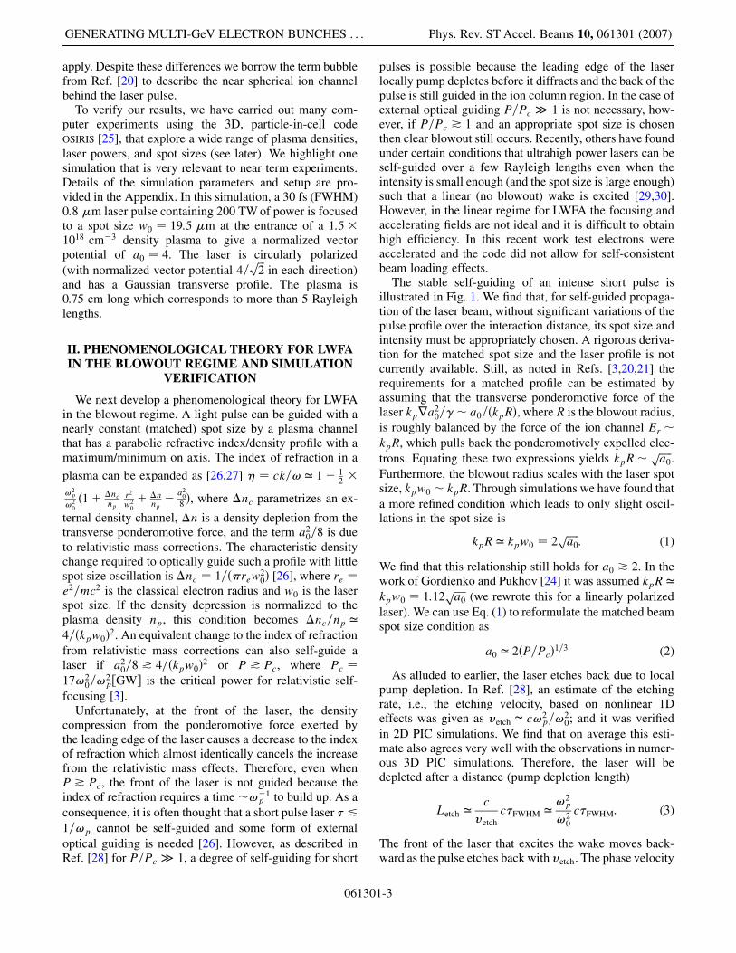
pulses is possible because the leading edge of the laserlocally pump depletes before it diffracts and the back of thepulse is still guided in the ion column region. In the case ofexternal optical guiding P=Pc � 1 is not necessary, how-ever, if P=Pc * 1 and an appropriate spot size is chosenthen clear blowout still occurs. Recently, others have foundunder certain conditions that ultrahigh power lasers can beself-guided over a few Rayleigh lengths even when theintensity is small enough (and the spot size is large enough)such that a linear (no blowout) wake is excited [29,30].However, in the linear regime for LWFA the focusing andaccelerating fields are not ideal and it is difficult to obtainhigh efficiency. In this recent work test electrons wereaccelerated and the code did not allow for self-consistentbeam loading effects.
The stable self-guiding of an intense short pulse isillustrated in Fig. 1. We find that, for self-guided propaga-tion of the laser beam, without significant variations of thepulse profile over the interaction distance, its spot size andintensity must be appropriately chosen. A rigorous deriva-tion for the matched spot size and the laser profile is notcurrently available. Still, as noted in Refs. [3,20,21] therequirements for a matched profile can be estimated byassuming that the transverse ponderomotive force of thelaser kpra2
0=�� a0=�kpR�, where R is the blowout radius,is roughly balanced by the force of the ion channel Er �kpR, which pulls back the ponderomotively expelled elec-trons. Equating these two expressions yields kpR�
�����a0p
.Furthermore, the blowout radius scales with the laser spotsize, kpw0 � kpR. Through simulations we have found thata more refined condition which leads to only slight oscil-lations in the spot size is
kpR ’ kpw0 � 2�����a0p
: (1)
We find that this relationship still holds for a0 * 2. In thework of Gordienko and Pukhov [24] it was assumed kpR ’kpw0 � 1:12
�����a0p
(we rewrote this for a linearly polarizedlaser). We can use Eq. (1) to reformulate the matched beamspot size condition as
a0 ’ 2�P=Pc�1=3 (2)
As alluded to earlier, the laser etches back due to localpump depletion. In Ref. [28], an estimate of the etchingrate, i.e., the etching velocity, based on nonlinear 1Deffects was given as �etch ’ c!2
p=!20; and it was verified
in 2D PIC simulations. We find that on average this esti-mate also agrees very well with the observations in numer-ous 3D PIC simulations. Therefore, the laser will bedepleted after a distance (pump depletion length)
Letch ’c
�etchc�FWHM ’
!2p
!20
c�FWHM: (3)
The front of the laser that excites the wake moves back-ward as the pulse etches back with �etch. The phase velocity
GENERATING MULTI-GeV ELECTRON BUNCHES . . . Phys. Rev. ST Accel. Beams 10, 061301 (2007)
061301-3

of the wake can therefore be expressed as �� ’ �g � �etch,where �g is the linear group velocity of light in a veryunderdense plasma !2
p � !20; therefore �� ’ c1�
3!2p=�2!
20�. The fact that the phase velocity of a wake
excited by an intense laser was less than even the lineargroup velocity of a laser was first discussed in [31]. Thedistance that the trapped electrons travel until they outrunthe wave (dephasing length) is
Ld ’c
c� ��R ’
2
3
!20
!2pR: (4)
We find in numerous 1D, 2D, and 3D simulations thatthe etching velocity and hence this dephasing estimate
works well for 2 & a0 & 2����ncn0
q. The estimate for the upper
value of a0 is discussed later.To illustrate the process of local pump depletion and its
relationship to photon deceleration [27], we plot the wavenumber, kz�z�, of one component of the laser’s electric field�Ex� after it has propagated through 0.18 cm of plasma forthree different laser intensities, a0 � 1; 4; 10 in Fig. 2. Forthe corresponding simulations in Figs. 2(a) and 2(b), a0 �4 but the pulse length was 30 and 50 fs, respectively. For
FIG. 1. (Color) A sequence of 2-dimensional slices �x� z� reveals the evolution of the accelerating structure (electron density, blue)and the laser pulse (orange). Each plot is a rectangular of size z � 101:7 �m (longitudinal direction, z) and x � 129:3 �m (transversedirection, x). A broken white circle is superimposed on each plot to show the shape of the blown-out region. When the front of the laserhas propagated a distance (a) z � 0:3 mm, the matched laser pulse has clearly excited a wakefield. Apart from some local modificationdue to beam loading effects, as seen in (b) this wakefield remains robust even as the laser beam propagates though the plasma adistance of 7.5 mm [as seen in (c) and (d)] or 5 Rayleigh lengths. After the laser beam has propagated 2 mm [as seen in (b)] into theplasma, one can clearly see self-trapped electrons in the first accelerating bucket. The radial and longitudinal localization of the self-trapped bunch is evident in part (c). After 7.5 mm the acceleration process terminates as the depleted laser pulse starts diffracting.
W. LU et al. Phys. Rev. ST Accel. Beams 10, 061301 (2007)
061301-4

the other two cases, the pulse length was 50 fs. In each casethe plasma density was 1:5� 1018 cm�3. The laser spotsize was matched according to Eq. (1) for the first threecases and was 24 �m for the case (d). The leading edge ofthe laser does work by pushing electrons forward andoutward, and the index of refraction is modified by thecombined effects of the electron density decrease and therelativistic mass increase. One way to view pump depletionis that the gradient of the index of refraction leads to adecrease in the laser frequency (photon deceleration) and,because the number of photons is an invariant, a depletionto the laser’s energy [27]. As the laser intensity is increasedthis gradient becomes steeper and more localized to thefront of the laser. This is seen in Fig. 2, where for a0 � 1
the spectra has a U shape [32] and the very front is notabsorbed, while for a0 � 10 only the front decreases andthe back is not effected. A chirp in wave number (fre-quency) can lead to pulse compression since the fasterphotons in the tail catch the slower photons in the headof the beam [32–35]. However, in nonlinear wakes theelectron density on axis is nearly zero so the relative phaseslippage between the photons with different frequency willbe less. In nonlinear wakes the front of the laser can also beabsorbed before it diffracts [28]. The spectra for a0 � 4 aremuch more similar to the a0 � 10 case than to the a0 � 1case. In Ref. [28] the scaling for the etching rate was alsoobtained from the energy given to the plasma electronsfrom a laser. Deriving a more rigorous theory for the phase
FIG. 2. (Color) Four plots depicting the Wigner transform of the x component of the laser electric field in the middle of the simulationbox and the relative permittivity as functions of z. The Wigner transform of a function ’�z� is defined as [39] W’�z; k� �R1�1 e
�ikz0’�z� z02�’
�z� z02�dz
0 and the relative permittivity valid under the quasistatic approximation is "r � �2 � 1�npnc
11� .
In each plot, the vertical axis on the left corresponds to the local wave number over the initial laser wave number and the vertical axison the right to "r. The four plots represent results from four different computer simulations after 0.18 cm of laser propagation into aplasma with np � 1:5� 1018 cm�3. (a) A 3D simulation of a 30 fs laser with a0 � 4 and matched profile. (b) A 2D simulation of a50 fs laser with a0 � 4 and matched profile. (c) A 2D simulation of a 50 fs laser with a0 � 10 and matched profile. (d) A 2Dsimulation of a 50 fs laser with a0 � 1. Plot (c) is typical for the ultrarelativistic blowout regime while plot (d) is typical for the linearregime. Plots (a) and (b), which result from simulations with a0 � 4, are more similar to the ultrarelativistic blowout case.
GENERATING MULTI-GeV ELECTRON BUNCHES . . . Phys. Rev. ST Accel. Beams 10, 061301 (2007)
061301-5

velocity of the wake in the blowout regime and speeding itup by modifying the initial pulse shape and frequencyspectra are areas for future work.
For the energy gain we may write the obvious equation
�E � qELWLacc � LWlaccmc2; (5)
where ELW is the average accelerating field of the beamloaded wake, Lacc is the acceleration length, LW �
eELW=�mc!p� and lacc � !pLacc=c. The desired accelera-tion length is the dephasing length, so we impose thecondition Letch >Ld ) c�FWHM > 2R=3. If the pulse istoo short dephasing will not be reached, and the electronbeam may have significant energy spread. We note that thiscondition is approximate, since the laser starts diffractingas soon as its intensity is insufficient to sustain self-focusing and this happens before the pulse is completelypump depleted. Additionally, the injected particles need toslightly pass the dephasing point (phase space rotation) sothat the energy spread is minimum. On the other hand, thelength of the pulse should not be too large, because thelaser field could interact with the trapped electrons anddegrade the beam quality [7,13].
We need an expression for LW which is the averageaccelerating field experienced by an electron, hEzi. InRef. [21] it was shown that for a0 * 4 the ion columnformed a sphere and that the accelerating field, for the mostpart, depends linearly on the distance from the middle ofthe sphere [Fig. 3(a)]. This is confirmed in Figs. 1(a)–1(c),where a bubble void of electrons roughly forms a circle andin Figs. 3(a) and 3(b) where a lineout of eEz=�mc!p� alongthe axis is shown. We also found by theory and 3D PICsimulations that a spherical shape is still roughly formedfor 2 & a0 & 4 with matched laser profiles. Interestingly,although the physics is very different, the nonlinear wakesformed in 1D also exhibit a linear slope of the sameamount.
Because the bubble is roughly a sphere and the electronsare either self-injected or externally injected at the rear, theelectrons then travel a relative distance R before theydephase. The peak useful accelerating field iseEz;max=�mc!p� �
�����a0p
and because the wakefield isroughly linear, the average field is half of the peak: LW �
eEz;max=�2mc!p� ’�����a0p
=2. We can therefore write theapproximate equation for the energy gain:
�E ’2
3mc2
�!0
!p
�2a0 ’ mc
2
�P
m2c5=e2
�1=3�ncnp
�2=3
�EGeV ’ 1:7�PTW
100
�1=3�
1018
npcm�3
�2=3�
0:8�0�m
�4=3:
(6)
We emphasize the much stronger dependence of thebeam energy on the plasma density than on the input laserpower. However, when the plasma density is lowered forfixed power, ensuring self-guided propagation of the lead-
FIG. 3. (Color) (a) A lineout of the wakefield along the z axisafter 0.3 mm shows that within the first bucket the slope of thewakefield is nearly constant and equal to eEz=�mc!p� ’ =2,where � kp�ct� z�. After 5.7 mm of propagation (b) thewakefield has been modified by beam loading (flattening of thewake between 400–450c=!p). This is corroborated by the pz vsz plot that is superimposed on the lineout of the wakefield.Panels (a) and (b) reveal that the acceleration mechanism isextremely stable during the simulation. The energy spectrumafter 7.5 mm (c) exhibits an isolated spike of 0.3 nC at 1.5 GeVwith energy spread ��=� � 3:8% corresponding to the firstbucket and a second spike of 50 pC at 700 MeV with energyspread ��=� � 1:5% corresponding to the second bucket.
W. LU et al. Phys. Rev. ST Accel. Beams 10, 061301 (2007)
061301-6

ing edge of the laser is more challenging. This can beaccomplished by plasma channels or to some degree byself-guiding. As we argue later, for self-guiding to occurP=Pc needs to increase as the plasma density decreases.We can rewrite Eq. (6) in terms of the critical power forrelativistic self-focusing, Pc:
�EGeV ’ 3:8�PPc
��2=3 PTW
100: (7)
On the other hand, if a plasma channel is used, P=Pc can bekept as low as 1. As shown before, the channel depth�nc=np needed is 4=�kpw0�
2 ’ 1=a0. So as long as a0 *
2 is used, the normalized channel depth is small (less than0:5). It is also worth noting here that, when a channel isused, the channel parameters (width and depth) should bechosen based on the matching condition for given laserpower and plasma density [Eqs. (1) and (2)] so that theleading front of the laser is guided by the density channeland the back of the laser is guided by the matched ionchannel.
The electrons which are accelerated can be either self-injected as shown in our sample simulation [Fig. 1(b)] orexternally injected from some other source. For self-injection, particles in the rear of the blowout region mustbe able to catch up with the wake. The physical conditionfor this to happen is twofold: first, the blowout radiusshould be large enough so that, when the particles reachthe rear of the bubble, they move predominately in theforward direction with speed close to the speed of light.Second, at the rear portion of the ion channel, trajectorycrossing occurs leading to a narrow sheath with the highestaccelerating and focusing fields. Therefore, even thoughelectrons initially have a � (energy) substantially below thewake’s Lorentz factor ��, they can easily achieve suffi-
cient energy as they are accelerated while they slowly driftbackwards (relatively to the pulse) in the sheath. In oursample simulation, the effective �� of the wake is around20 and the normalized blowout radius is around 4. Theinitial energy � of those trapped electrons is substantiallysmaller than 20. For even lower plasma densities, we haveperformed a number of simulations, where an electronbeam with � exceeding 10 000 was used as the driverinstead of a laser and we observed self-injected electronsin each case for a normalized blowout radius around 5.This indicates that for laser wavelengths in the 0:8 �mrange and plasma densities of interest, self-injection willalways happen when we keep the normalized blowoutradius around 4–5. This differs significantly from the claimin Ref. [20] that
�����a0p
> ��, or a0 > 400 for our samplesimulation, for self-trapping to occur.
In the regime presented here, the self-injected electronbunches are highly localized in space with a half-width ofthe first bunch of only�10 fs, i.e. 1c=!p. Once a sufficientnumber of electrons have been trapped the trapping processterminates, as seen in Fig. 1(c). The first electron bunchreaches an energy of 1.5 GeV and its energy spectrum ispresented in Fig. 3(c). The normalized emittances areshown in Fig. 4. They may be estimated as the product ofthe beam spot size, which roughly scales with 1= ������npp , withthe spread in the momentum perpendicular to the accel-eration direction, which scales with the relativistic pon-deromotive potential (� a0). These simple considerationsshow that as we move to lower densities in order to achievehigher-energy particles the emittances of the self-injectedelectrons will increase. This suggests that, for the electronbeam to be useful for high-energy physics or light source,external injection may be more attractive. As an interestingaside, simulations also reveal the trapping and acceleration
FIG. 4. (Color) The normalized emittance "Ni � �����������������������������������������������������h�p2
i ih�x2i i � h�pi�xii
2q
(where �pi is normalized as indicated by the figureand the emittance is in units of �xi) and is the approximate area in phase space pixi. For the panels above which correspond to the firstbunch, this formula yields "Nx ’ 35� mm rad and "Ny ’ 29� mm rad. An upper limit for the emittance can be found bymultiplying the typical divergences shown in the figure; this method leads to an overestimation which for this case is about 25%.For the second bunch of accelerated electrons (not shown in this figure), the emittances are significantly lower: "Nx ’ 10� mm radand "Ny ’ 11� mm rad.
GENERATING MULTI-GeV ELECTRON BUNCHES . . . Phys. Rev. ST Accel. Beams 10, 061301 (2007)
061301-7
of a second distinct bunch in the second bucket [seeFig. 3(c)], which has a lower energy because the averageelectric field it experiences is smaller.
The number, N, of electrons that are accelerated can beestimated from energy balance. Hence, we examine thepartition of field and particle energy within the first bucket.The fields inside the ion column have Ez, Er, and B�components. In addition there is kinetic energy in theplasma. In a 3D linear or 1D nonlinear wake the fieldsand kinetic energy scale together. This is not the case forthese 3D nonlinear wakes where an increasing percentageof energy ends up in electrons which are blown out wellbeyond the narrow electron sheath for higher laser inten-sity. Integrating the field energy in the ion channel we findequipartition between the energy in the longitudinal fieldEl and the focusing fields Ef:
E l ’ Ef ’1
2E �
1
120�kpR�
5
�m2c5
e2!p
�: (8)
The trailing particles can recover the field energy in theion channel and the kinetic energy in the narrow electronsheath by changing the shape of the ion channel. Thekinetic energy in the narrow electron sheath scales thesame way as the field energy. By equating E with theenergy absorbed by N particles that travel across the ionchannel (we assume the average field felt by these particlesis Ez;max=2 and the kinetic energy in the electron sheathabsorbed by the trailing particles is the same as the fieldenergy), we obtain
N ’1
30�kpR�
3 1
kpre�
��3
�
�8=15
k0re
������������������P
m2c5=e2
s; (9)
where � � kpw0=�2�����a0p� and � � kpR=�2
�����a0p�. Using
Eq. (1) � ’ 1 ’ � we obtain
N ’8=15
k0re
������������������P
m2c5=e2
s’ 2:5� 109 �0�m
0:8
���������������PTW
100
s: (10)
The efficiency scales as the total energy Eb in theaccelerated electron beam [energy gain Eq. (6) times par-ticle number from Eq. (9)] divided by the total laser energyET (assuming c� ’ 2
���apc=!p0):
�� Eb=ET � 1=a0 (11)
which indicates that a0, i.e., �P=Pc�1=3 cannot be too largeif one needs high efficiency. For a 200 TW, 0:8 �m pulse,Eq. (10) predicts 0.6 nC of charge. The charge measuredfrom the simulation for the first bunch is 0.3 nC. We havealso verified these scaling laws by monitoring how manyelectrons can be externally injected before the wake be-comes severely loaded.
As shown in Fig. 1(d), the acceleration process stopsbefore the accelerating bunch dephases. This will not lead
to any considerable modifications of the aforementionedformulas, particularly because the pump depletion lengthscales as the dephasing distance and the accelerating wake-field decreases as the trapped electrons approach the centerof the sphere.
The beam energy seen in the simulation, 1.5 GeV, isclose to that calculated theoretically from Eq. (6) which is�6� ) �W ’ 1:6 GeV. Using formulas (3) and (4), we seeLd ’ 1:31 cm > 0:96 cm ’ Lpd which is in agreementwith our observation that pump depletion happened beforedephasing. In addition, as the laser pump depleted its rateof diffraction increased such that the effective accelerationlength was eventually limited by diffraction to a distance0.75 cm which was less than the pump depletion distance0.96 cm. For a wake with a linear slope most of the energygain occurs near the peak field. This combined with thedensity spike at the back of the bucket is why the estimatefrom Eq. (6) is still so accurate for this nonoptimizedsample simulation.
In spite of the complexity of the physics associated withthis interaction, the predictions by the simple formulaspresented in this article are very close to 3D PIC simulationresults. Good agreement is also achieved between thesescaling laws and recent experimental results [10–12] de-spite the fact that the laser powers were slightly below the‘‘threshold’’ for the blowout regime and the laser pulse wasnot matched transversely nor longitudinally. To be in theregime identified by a spherical bubble, one needs a0 * 4or equivalently P=Pc * 8 and c� < 2
�����a0p
c=!p whichleads to the condition that P * 30��=30 fs� TW. Theseconditions can be relaxed for channel-guided lasers forwhich P=Pc may be smaller. It is then written as a0 * 2or P=Pc * 1. We present the comparison between thescaling law for the energy Eq. (6) and the aforementionedresults in Fig. 5.
The scalings derived above and the underlying physicspredict that it is advantageous to use moderate intensitiesand very low plasma densities to increase the output energyand keep the efficiency high. The simulations also showthat the injection process can be clamped and the energyspread of the electron beam is much less in the regime weare proposing, which indicates that this regime is alsoamenable to accelerating externally injected beams whilemaintaining good beam quality.
In Table I we compare some of our results to previouslypublished work [24,26]. Both linear and 1D nonlinearformulas fail to describe the 3D nonlinear regime in nearlyall respects. It is however instructive to compare the scalinglaws described above against those obtained in Ref. [24]using a similarity theory for the high intensity high plasmadensity regime, because in Ref. [24] the scaling (but not thecoefficients) of the fields in the bubble and the laser spotsize with a0 were identified correctly. The key assumptionof Ref. [24] required that a0 � 1. For the energy gain, theyobtained
W. LU et al. Phys. Rev. ST Accel. Beams 10, 061301 (2007)
061301-8
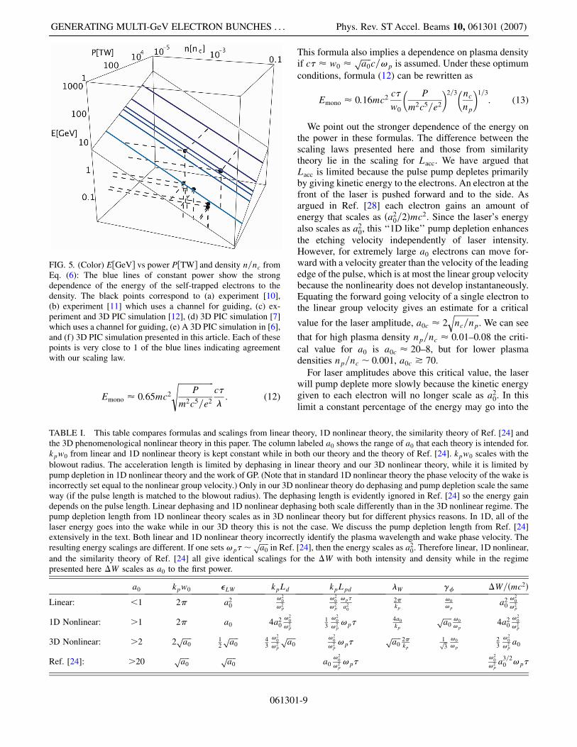
Emono � 0:65mc2
������������������P
m2c5=e2
sc��: (12)
This formula also implies a dependence on plasma densityif c� � w0 �
�����a0p
c=!p is assumed. Under these optimumconditions, formula (12) can be rewritten as
Emono � 0:16mc2 c�w0
�P
m2c5=e2
�2=3�ncnp
�1=3: (13)
We point out the stronger dependence of the energy onthe power in these formulas. The difference between thescaling laws presented here and those from similaritytheory lie in the scaling for Lacc. We have argued thatLacc is limited because the pulse pump depletes primarilyby giving kinetic energy to the electrons. An electron at thefront of the laser is pushed forward and to the side. Asargued in Ref. [28] each electron gains an amount ofenergy that scales as �a2
0=2�mc2. Since the laser’s energyalso scales as a2
0, this ‘‘1D like’’ pump depletion enhancesthe etching velocity independently of laser intensity.However, for extremely large a0 electrons can move for-ward with a velocity greater than the velocity of the leadingedge of the pulse, which is at most the linear group velocitybecause the nonlinearity does not develop instantaneously.Equating the forward going velocity of a single electron tothe linear group velocity gives an estimate for a critical
value for the laser amplitude, a0c � 2�������������nc=np
q. We can see
that for high plasma density np=nc � 0:01–0:08 the criti-cal value for a0 is a0c � 20–8, but for lower plasmadensities np=nc � 0:001, a0c * 70.
For laser amplitudes above this critical value, the laserwill pump deplete more slowly because the kinetic energygiven to each electron will no longer scale as a2
0. In thislimit a constant percentage of the energy may go into the
FIG. 5. (Color) EGeV vs power PTW and density n=nc fromEq. (6): The blue lines of constant power show the strongdependence of the energy of the self-trapped electrons to thedensity. The black points correspond to (a) experiment [10],(b) experiment [11] which uses a channel for guiding, (c) ex-periment and 3D PIC simulation [12], (d) 3D PIC simulation [7]which uses a channel for guiding, (e) A 3D PIC simulation in [6],and (f) 3D PIC simulation presented in this article. Each of thesepoints is very close to 1 of the blue lines indicating agreementwith our scaling law.
TABLE I. This table compares formulas and scalings from linear theory, 1D nonlinear theory, the similarity theory of Ref. [24] andthe 3D phenomenological nonlinear theory in this paper. The column labeled a0 shows the range of a0 that each theory is intended for.kpw0 from linear and 1D nonlinear theory is kept constant while in both our theory and the theory of Ref. [24]. kpw0 scales with theblowout radius. The acceleration length is limited by dephasing in linear theory and our 3D nonlinear theory, while it is limited bypump depletion in 1D nonlinear theory and the work of GP. (Note that in standard 1D nonlinear theory the phase velocity of the wake isincorrectly set equal to the nonlinear group velocity.) Only in our 3D nonlinear theory do dephasing and pump depletion scale the sameway (if the pulse length is matched to the blowout radius). The dephasing length is evidently ignored in Ref. [24] so the energy gaindepends on the pulse length. Linear dephasing and 1D nonlinear dephasing both scale differently than in the 3D nonlinear regime. Thepump depletion length from 1D nonlinear theory scales as in 3D nonlinear theory but for different physics reasons. In 1D, all of thelaser energy goes into the wake while in our 3D theory this is not the case. We discuss the pump depletion length from Ref. [24]extensively in the text. Both linear and 1D nonlinear theory incorrectly identify the plasma wavelength and wake phase velocity. Theresulting energy scalings are different. If one sets!p��
�����a0p
in Ref. [24], then the energy scales as a20. Therefore linear, 1D nonlinear,
and the similarity theory of Ref. [24] all give identical scalings for the �W with both intensity and density while in the regimepresented here �W scales as a0 to the first power.
a0 kpw0 LW kpLd kpLpd �W �� �W=�mc2�
Linear: <1 2� a20
!20
!2p
!20
!2p
!p�a2
0
2�kp
!0
!pa2
0!2
0
!2p
1D Nonlinear: >1 2� a0 4a20!2
0
!2p
13
!20
!2p!p�
4a0
kp
�����a0p !0
!p4a2
0!2
0
!2p
3D Nonlinear: >2 2�����a0p 1
2
�����a0p 4
3
!20
!2p
�����a0p !2
0
!2p!p�
�����a0p 2�
kp1��3p !0
!p
23
!20
!2pa0
Ref. [24]: >20�����a0p �����
a0p
a0!2
0
!2p!p�
!20
!2pa3=2
0 !p�
GENERATING MULTI-GeV ELECTRON BUNCHES . . . Phys. Rev. ST Accel. Beams 10, 061301 (2007)
061301-9
fields of the wake such that �� constant as predictedby Ref. [24]. The pump depletion length, Lpd, canthen be estimated from energy balance between the laser
and the wakefields,E2
0
8� c� �E2z
8�Lpd ) Lpd �a2
0
2 �
!20
!2pc� � 1
4a0!2
0
!2pc�� a0Letch which does depend on a0.
Using this scaling for Lacc in Eq. (5) provides the samescaling for the particle energy as obtained from similaritytheory. However, even for this high intensity limit dephas-ing will still occur because the leading edge cannot movefaster than the linear group velocity of the highest fre-quency component, since at the very front the amplitudeis small [31].
Last, it is useful to extrapolate this nonlinear regime formoderate a0 to 10 GeVand beyond. If we keep P=Pc fixed,then the laser power and inverse of the density scale withthe desired electron energy and the pulse length will scaleas the electron energy to the 1=2 power. If we scale up oursample simulation, to obtain 15 GeV we need a 2 PW,100 fs laser and a plasma with density of 1:5� 1017 cm�3.The only uncertainty is whether self-guiding is stillpossible.
To obtain the condition for self-guiding, we resort to
quasistatic theory where the index of refraction � ’ 1�
12!2p
!20
11� and @2
@2 �k2p
2 1�a2
�1� �2 � 1 � 0. As noted earlier
1� 11� ’ must equal 4=�kpw0�
2 in order for guiding
to occur. For j j � 1, we assume @2 @2 ’
k2p
2 a2; therefore
builds up to the necessary value in a distance � whichscales as �� �k2
pw0a0��1 � �kpa
3=20 �
�1. The length of
the laser that is lost due to diffraction each Rayleigh length(ZR) will also scale as �kpa
3=20 �
�1. Self-guiding can beachieved if the length lost due to pump depletion in eachRayleigh length also scales the same way:
�etch
c’
3
2
npnc�
�ZR) a0 � �nc=np�
1=5: (14)
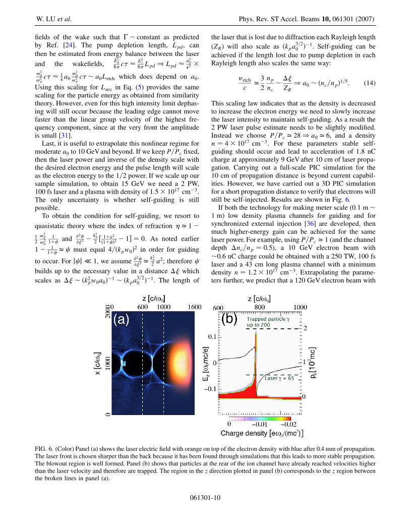
This scaling law indicates that as the density is decreasedto increase the electron energy we need to slowly increasethe laser intensity to maintain self-guiding. As a result the2 PW laser pulse estimate needs to be slightly modified.Instead we choose P=Pc ’ 28) a0 ’ 6, and a densityn � 4� 1017 cm�3. For these parameters stable self-guiding should occur and lead to acceleration of 1.8 nCcharge at approximately 9 GeV after 10 cm of laser propa-gation. Carrying out a full-scale PIC simulation for the10 cm of propagation distance is beyond current capabil-ities. However, we have carried out a 3D PIC simulationfor a short propagation distance to verify that electrons willstill be self-injected. Results are shown in Fig. 6.
If both the technology for making meter scale (0:1 m�1 m) low density plasma channels for guiding and forsynchronized external injection [36] are developed, thenmuch higher-energy gain can be achieved for the samelaser power. For example, using P=Pc ’ 1 (and the channeldepth �nc=np � 0:5), a 10 GeV electron beam with�0:6 nC charge could be obtained with a 250 TW, 100 fslaser and a 43 cm long plasma channel with a minimumdensity n � 1:2� 1017 cm�3. Extrapolating the parame-ters further, we predict that a 120 GeV electron beam with
FIG. 6. (Color) Panel (a) shows the laser electric field with orange on top of the electron density with blue after 0.4 mm of propagation.The laser front is chosen sharper than the back because it has been found through simulations that this leads to more stable propagation.The blowout region is well formed. Panel (b) shows that particles at the rear of the ion channel have already reached velocities higherthan the laser velocity and therefore are trapped. The region in the z direction plotted in panel (b) corresponds to the z region betweenthe broken lines in panel (a).
W. LU et al. Phys. Rev. ST Accel. Beams 10, 061301 (2007)
061301-10

2.2 nC charge generated by using a 3 PW, 350 fs laser and18 m long plasma channel with density n � 1:0�1016 cm�3.
For high-energy physics applications, where the energyfrontier exceeds 100 GeV, the synchrotron radiation ofelectron beams in the focusing fields of the wake caninduce significant energy loss, energy spread, and emit-tance damping.
In order to reduce the energy spread electron beam withsmall spot size will be required. The energy spread can beestimated by calculating the power radiated by a single
electron, P � 23e2
c �6�
_~��2 � � ~�� _~��2 [37]. For an elec-tron executing betatron oscillations with a frequency!p=
������2�p
, the ratio of energy loss due to synchrotronradiation to the energy gain in the accelerating field istherefore
rLW
�����
1
6
1
LW
re 2r�
2
�c=!p�3
� 1:2� 10�4 1
LW� r�m�2�Eb100 GeV�2
��np1016 cm�3�3=2; (15)
where r is the normalized retarding field, LW is thenormalized accelerating field, re is the classical electronradius, and r is the spot size of the beam. For the 120 GeVexample given above where � 2, np � 1016 cm�3, thenin order for ��=� < 10�2, the spot size r should be lessthan 10 �m. For such a spot size, a bunch length �c=!p
and a charge of 2.2 nC, the ratio of the beam density to theplasma density is 17.
The beam’s spot size will decrease and hence the nor-malized emittance will also decrease because those elec-trons at the larger radii will radiate more. The normalizedemittance scales as � !p�����
2�p 2
r while !p�����2�p 2
r is an adiabatic
invariant. Therefore, �NN� ��
� . A more detailed calcula-tion of these effects for an ensemble of electrons wasrecently made by Michel et al. [38].
III. CONCLUSION
In conclusion, we have presented a phenomenologicaltheory for LWFA in the nonlinear blowout regime. Thistheory includes the concepts of nonlinear multidimen-sional wake excitation, local pump depletion, dephasing,laser guiding, and beam loading. This theory provides arecipe for designing a LWFA for given laser and plasmaparameters and estimates the number and the energy of theaccelerated electrons whether self-injected or externallyinjected. These formulas apply for self-guided as well asexternally guided pulses (e.g. by plasma channels). Wehave compared the scaling laws for this nonlinear regimewith those derived for 1D linear, 1D nonlinear, and therecent 3D similarity theory. We have examined this regime
via PIC simulations, and presented results of a 30 fs,200 TW laser interacting with a 0.75 cm long plasmawith a density 1:5� 1018 cm�3. In this simulation anultrashort (10 fs) monoenergetic bunch of self-injectedelectrons at 1.5 GeV with 0.3 nC of charge was observed.For future higher-energy accelerator applications (GeVandbeyond), we propose to use externally injected electronbeams to maintain high beam quality and to avoid darkcurrent.
We close by commenting on how our work might beapplied to the parameters of the recently published experi-mental results in which a 1 GeV monoenergetic electronbeam was observed. In this experiment a 40 TW 40 fs(12 TW 70 fs) laser was propagated in a shallow plasmachannel of density �4:3� 1018 cm�3 (� 3:2�1018 cm�3). In the experiment, neither the laser spot sizenor the pulse length was initially matched (initially W0 �25 �m). For example, for this density a 40 TW laser
should have a matched spot size W0 � 2����������������2� PPc�
1=3q
c=!p �
10 �m and a pulse length of 30 fs. Therefore, in thisexperiment the laser will evolve significantly, both longi-tudinally and transversely so that applying our scaling lawsis not completely appropriate. Nevertheless, for these pa-rameters, Eq. (6) predicts an output energy of 0.5 GeV,while the experimentally observed value was 1.0 GeVwhich is within a factor of 2 . The interpretation of thisexperimental result is likely to be more similar to that inTsung et al. [7], where a 16 TW laser produced a somewhatmonoenergetic beam at 0.7 GeV (in Fig. 1 of this reference,the electron spectra were on a log scale). However, in thesimulations of Tsung et al. the channel was narrower.
ACKNOWLEDGMENTS
The work is supported by DOE under Grants No. DE-FC02-01ER41179, No. DE-FG02-03ER54721, No. DE-FG03-92-ER4727, No. DE-FG03-NA0065, and No. DE-FG52-06NA26195, by NSF under Grant No. Phy-0321345,and by FCT (Portugal). The simulations were performedon Dawson cluster, maintained locally by UCLA/ATS, andon the IBM SP at NERSC under mp113 and gc2. Weacknowledge very useful conversations with Professor T.Katsouleas and Professor A. Pukhov.
APPENDIX: PARAMETERS AND SETUP
The simulation for the 200 TW, 30 fs laser pulse in afully ionized n � 1:5� 1018 cm�3 plasma has a computa-tional window of dimension 101:9� 127:3� 127:3 �m3
which moves at the speed of light. The number of grid-points is 4000� 256� 256 � 2:62� 108. The resolutionin the laser propagation direction z is k0�z � 0:2. Weassume a preformed fully ionized plasma with uniformdensity profile. The resolution in the transverse directionis kp�x � kp�y � 0:116. We use 2 electrons per cell anda smooth neutralizing immobile ion background (the total
GENERATING MULTI-GeV ELECTRON BUNCHES . . . Phys. Rev. ST Accel. Beams 10, 061301 (2007)
061301-11

number of particles is roughly 500 million). A diffractionlimited, circularly polarized pulse is focused at the plasmaentrance with a spot size w0 � 19:5 �m and the electricfield has a symmetric temporal profile of 10�3 � 15�4 �
6�5, where � ����2p�t� t0�=�FWHM. The laser is Gaussian
in the transverse direction. The total axial length of theplasma is close to 0.75 cm, or 3000 000 simulation timesteps.
The simulation for the 2 PW, 100 fs, w0 � 40 �m laserin plasma density n � 4� 1017 has a computational win-dow of dimension 203:8� 127:3� 127:3 �m3 which cor-responds to 8000� 256� 256 � 5:24� 108 gridpointswith identical resolution as in the aforementioned200 TW run. Roughly 1 billion particles were used andran 16 000 simulation time steps. The rise time of the laserwas about 2.5 times shorter than the fall time.
[1] T. Tajima and J. M. Dawson, Phys. Rev. Lett. 43, 267(1979).
[2] P. Chen, J. M. Dawson, Robert W. Huff, and T. Katsouleas,Phys. Rev. Lett. 54, 693 (1985).
[3] Guo-Zheng Sun, Edward Ott, Y. C. Lee, and PervezGuzdar, Phys. Fluids 30, 526 (1987).
[4] J. B. Rosenzweig, B. Breizman, T. Katsouleas, and J. J. Su,Phys. Rev. A 44, R6189 (1991).
[5] W. B. Mori, T. Katsouleas, C. B. Darrow, C. E. Clayton, C.Joshi, J. M. Dawson, C. B. Decker, K. Marsh, and S. C.Wilks, Proceedings of the Particle Accelerator Con-ference. San Francisco, California, 1991.
[6] A. Pukhov and J. Meyer-ter-vehn, Appl. Phys. B 74, 355(2002).
[7] F. S. Tsung, Ritesh Narang, W. B. Mori, C. Joshi, R. A.Fonseca, and L. O. Silva, Phys. Rev. Lett., 93, 185002(2004).
[8] M. Hogan et al., Phys. Rev. Lett. 95, 054802 (2005).[9] I. Blumenfeld et al., Nature (London) 445, 741 (2007).
[10] S. P. D. Mangles et al., Nature (London) 431, 535(2004).
[11] C. G. R. Geddes et al., Nature (London) 431, 538 (2004).[12] J. Faure et al., Nature (London) 431, 541 (2004).[13] S. P. D. Mangles et al., Phys. Rev. Lett. 96, 215001 (2006).[14] C.-T. Hsieh, C.-M. Huang, C.-L. Chang, Y.-C. Ho, Y.-S.
Chen, J.-Y. Lin, J. Wang, and S.-Y. Chen, Phys. Rev. Lett.96, 095001 (2006).
[15] W. P. Leemans et al., Nature Phys. 2, 696 (2006).
[16] F. S. Tsung, W. Lu, M. Tzoufras, W. B. Mori, C. Joshi,J. M. Vieira, L. O. Silva, and R. A. Fonseca, Phys. Plasmas13, 056708 (2006).
[17] N. H. Matlis et al., Nature Phys. 2, 749 (2006).[18] T. Katsouleas, S. Wilks, P. Chen, J. M. Dawson, and J. J.
Su, Part. Accel. 22, 81 (1987).[19] P. Mora and T. M. Antonsen, Jr., Phys. Plasmas 4, 217
(1997).[20] I. Kostyukov, A. Pukhov, and S. Kiselev, Phys. Plasmas
11, 5256 (2004).[21] W. Lu, C. Huang, M. Zhou, W. B. Mori, and T. Katsouleas,
Phys. Rev. Lett. 96, 165002 (2006).[22] W. Lu, C. Huang, M. Zhou, M. Tzoufras, F. S. Tsung,
W. B. Mori, and T. Katsouleas, Phys. Plasmas 13, 056709(2006).
[23] V. Malka, J. Faure, Y. Glinnec, and A. F. Lifschitz, PlasmaPhys. Controlled Fusion 47, B481 (2005).
[24] S. Gordienko and A. Pukhov, Phys. Plasmas 12, 043109(2005).
[25] R. A. Fonseca et al., in ICCS 2002, LNCS 2331, edited byP. M. A. Sloot et al., 2002, pp. 342–351.
[26] E. Esarey, P. Sprangle, J. Krall, and A. Ting, IEEE Trans.Plasma Sci. 24, 252 (1996), and references therein.
[27] W. B. Mori, IEEE J. Quantum Electron. 33, 1942 (1997),and references therein.
[28] C. D. Decker, W. B. Mori, K.-C. Tzeng, and T. Katsouleas,Phys. Plasmas 3, 2047 (1996).
[29] L. M. Gorbunov, S. Yu. Kalmykov, and P. Mora, Phys.Plasmas 12, 033101 (2005).
[30] S. Yu. Kalmykov, L. M. Gorbunov, P. Mora, and G. Shvets,Phys. Plasmas 13, 113102 (2006).
[31] C. D. Decker and W. B. Mori, Phys. Rev. Lett. 72, 490(1994); Phys. Rev. E 51, 1364 (1995).
[32] D. F. Gordon, B. Hafizi, R. F. Hubbard, J. R. Peano, P.Sprangle, and A. Ting, Phys. Rev. Lett. 90, 215001 (2003).
[33] F. S. Tsung, C. Ren, L. O. Silva, W. B. Mori, and T.Katsouleas, PANS V.99, No. 1, 2002, p. 29–32.
[34] C. Ren, B. J. Duda, R. G. Hemker, W. B. Mori, T.Katsouleas, T. M. Antonsen, Jr., and P. Mora, Phys. Rev.E 63, 026411 (2001).
[35] J. Faure et al., Phys. Rev. Lett. 95, 205003 (2005).[36] J. Faure, C. Rechatin, A. Norlin, A. Lifschitz, Y. Glinnec,
and V. Malka, Nature (London) 444, 737 (2006).[37] J. D. Jackson, Classical Electrodynamics, 3rd Edition
(John Wiley and Sons, Inc., New York, 1998).[38] P. Michel, C. B. Schroeder, B. A. Shadwick, E. Esarey, and
W. P. Leemans, Phys. Rev. E 74, 026501 (2006).[39] S. Mallat, A Wavelet Tour of Signal Processing (Academic
Press, London, 1998), pp. 104–113.
W. LU et al. Phys. Rev. ST Accel. Beams 10, 061301 (2007)
061301-12